JP4223139B2 - Image generating apparatus and information storage medium - Google Patents
Image generating apparatus and information storage medium Download PDFInfo
- Publication number
- JP4223139B2 JP4223139B2 JP13952099A JP13952099A JP4223139B2 JP 4223139 B2 JP4223139 B2 JP 4223139B2 JP 13952099 A JP13952099 A JP 13952099A JP 13952099 A JP13952099 A JP 13952099A JP 4223139 B2 JP4223139 B2 JP 4223139B2
- Authority
- JP
- Japan
- Prior art keywords
- virtual camera
- image
- given
- fluctuation
- rotation
- Prior art date
- Legal status (The legal status is an assumption and is not a legal conclusion. Google has not performed a legal analysis and makes no representation as to the accuracy of the status listed.)
- Expired - Lifetime
Links
Images


Classifications
-
- A—HUMAN NECESSITIES
- A63—SPORTS; GAMES; AMUSEMENTS
- A63F—CARD, BOARD, OR ROULETTE GAMES; INDOOR GAMES USING SMALL MOVING PLAYING BODIES; VIDEO GAMES; GAMES NOT OTHERWISE PROVIDED FOR
- A63F2300/00—Features of games using an electronically generated display having two or more dimensions, e.g. on a television screen, showing representations related to the game
- A63F2300/60—Methods for processing data by generating or executing the game program
- A63F2300/66—Methods for processing data by generating or executing the game program for rendering three dimensional images
- A63F2300/6661—Methods for processing data by generating or executing the game program for rendering three dimensional images for changing the position of the virtual camera
- A63F2300/6684—Methods for processing data by generating or executing the game program for rendering three dimensional images for changing the position of the virtual camera by dynamically adapting its position to keep a game object in its viewing frustrum, e.g. for tracking a character or a ball
Description
【0001】
【発明の属する技術分野】
本発明は、画像生成装置及び情報記憶媒体に関する。
【0002】
【背景技術及び発明が解決しようとする課題】
従来より、仮想的な3次元空間であるオブジェクト空間内に複数のオブジェクトを配置し、仮想カメラの視点から見える画像を生成する画像生成装置(狭義にはゲーム装置)が知られており、いわゆる仮想現実を体験できるものとして人気が高い。レーシングゲームを楽しむことができる画像生成装置を例にとれば、プレーヤは、自身が運転する車(自車)をオブジェクト空間内で走行させ、他のプレーヤ又はコンピュータが運転する車(他車)と競争することでゲームを楽しむ。
【0003】
さて、このような画像生成装置では、プレーヤの仮想現実感の向上のために、よりリアルな画像を生成することが重要な技術的課題になっている。
【0004】
しかしながら、このような画像生成装置においては仮想カメラを実際に制御するのはコンピュータであるため、この仮想カメラから見える画像は、現実世界において人間が本当のカメラで撮った場合の画像とは異なったものにならざるを得ない。従って、得られる画像が今一つ単調であり、リアル感に欠けていた。
【0005】
例えば、プレーヤの運転する車(移動体)を、コース沿いに設置された仮想カメラにより撮る場合、車と仮想カメラとを結ぶベクトルを求め、そのベクトルの方向に仮想カメラを向ける手法が考えられる。この手法によれば、車が高速で移動しても、仮想カメラはその車を追うことができ、車が確実に画面内に入るようになる。
【0006】
しかしながら、この手法では、画面の中心に車が常に固定されてしまい、いかにもコンピュータ制御の仮想カメラで撮ったというような画像が生成されてしまう。従って、今一つプレーヤの仮想現実感を高めることができなかった。
【0007】
本発明は、以上のような課題を解決するためになされたものであり、その目的とするところは、仮想カメラから見える画像を少ない処理負担でよりリアルな画像にすることができる画像生成装置及び情報記憶媒体を提供することにある。
【0008】
【課題を解決するための手段】
上記課題を解決するために、本発明は、画像を生成するための画像生成装置であって、オブジェクト空間内の所与の視点での画像を生成するための仮想カメラを制御する手段と、仮想カメラの所与の軸回りでの回転及び仮想カメラの位置の少なくとも一方が変化した場合に、仮想カメラの所与の軸回りでの回転及び仮想カメラの位置の少なくとも一方に対して揺らぎを与える手段と、仮想カメラから見える画像を生成する手段とを含むことを特徴とする。また本発明に係る情報記憶媒体は、コンピュータにより使用可能な情報記憶媒体であって、上記手段を実現(実行)するための情報(プログラム)を含むことを特徴とする。また本発明に係るプログラムは、コンピュータにより使用可能なプログラムであって、上記手段を実現(実行)するためのプログラムであることを特徴とする。
【0009】
本発明によれば、仮想カメラが所与の軸回りで回転したり、仮想カメラが移動すると(位置が変化すると)、仮想カメラの軸回り回転或いは位置に対して、揺らぎが与えられる。そして、この揺らぎが与えられた仮想カメラから見える画像が生成される。従って、本発明によれば、あたかも手ぶれにより仮想カメラが振動したかのような錯覚を操作者(プレーヤ)に与えることができるようになり、画像の臨場感やリアル度を格段に高めることができる。
【0010】
また本発明に係る画像生成装置、情報記憶媒体及びプログラムは、オブジェクト空間内で移動する移動体に仮想カメラの注視点を追従させるために仮想カメラの所与の軸回りでの回転及び仮想カメラの位置の少なくとも一方が変化した場合に、仮想カメラの所与の軸回りでの回転及び仮想カメラの位置の少なくとも一方に対して揺らぎを与えることを特徴とする。本発明によれば、操作者による操作、コンピュータによる操作、或いは移動体の移動を再現するための情報等に基づいて、移動体がオブジェクト空間内で移動する。そして、この移動体に仮想カメラの注視点を追従させるために、仮想カメラが所与の軸回りで回転したり、仮想カメラが移動すると、仮想カメラに対して揺らぎが与えられるようになる。この結果、移動体を追う仮想カメラから見える画像のリアル度、臨場感を増すことができる。
【0011】
また本発明に係る画像生成装置、情報記憶媒体及びプログラムは、仮想カメラの回転角速度及び仮想カメラの速度の少なくとも一方に応じた揺らぎを、仮想カメラの所与の軸回りでの回転及び仮想カメラの位置の少なくとも一方に対して与えることを特徴とする。このようにすれば、仮想カメラの回転角速度(回転変化量)や速度(位置変化量)に基づいて、仮想カメラに揺らぎを与えるか否かを判断したり、上記回転角速度や上記速度に基づいて変化する揺らぎを、仮想カメラに与えたりすること等が可能になる。これにより、少ない処理負担で、よりリアルな画像を生成できるようになる。
【0012】
また本発明に係る画像生成装置、情報記憶媒体及びプログラムは、仮想カメラの回転角速度が速いほど広くなる、或いは仮想カメラの速度が速いほど広くなる揺らぎ範囲を求め、該揺らぎ範囲内の揺らぎを、仮想カメラの所与の軸回りでの回転及び仮想カメラの位置の少なくとも一方に対して与えることを特徴とする。このようにすれば、仮想カメラの回転角速度や速度に応じて変化する揺らぎ範囲内で、仮想カメラを揺らすことができるようになる。なお、この場合に、仮想カメラに与える揺らぎは、揺らぎ関数や揺らぎ値テーブルなどに基づいて求めることが望ましい。
【0013】
また本発明に係る画像生成装置、情報記憶媒体及びプログラムは、仮想カメラの回転角速度が所与の回転角速度より大きい場合、或いは仮想カメラの速度が所与の速度より大きい場合に、揺らぎの増加を制限することを特徴とする。このようにすれば、仮想カメラの回転角速度や速度が非常に大きくなることにより揺らぎが過大に大きくなる事態を、効果的に防止できるようになる。
【0014】
また本発明は、画像を生成するための画像生成装置であって、オブジェクト空間内で移動体を移動させる演算を行う手段と、オブジェクト空間内の所与の視点での画像を生成するための仮想カメラを制御する手段と、移動体の位置と仮想カメラの注視点位置との間のオフセット値を可変に制御しながら、オブジェクト空間内を移動する移動体に仮想カメラの注視点を追従させる手段と、仮想カメラから見える画像を生成する手段とを含むことを特徴とする。また本発明に係る情報記憶媒体は、コンピュータにより使用可能な情報記憶媒体であって、上記手段を実現(実行)するための情報(プログラム)を含むことを特徴とする。また本発明に係るプログラムは、コンピュータにより使用可能なプログラムであって、上記手段を実現(実行)するためのプログラムであることを特徴とする。
【0015】
本発明によれば、仮想カメラが移動体を追う際に、移動体位置と注視点位置の間のオフセット値(2次元距離、3次元距離、角度等)が可変に制御される。これにより、画面内での移動体の位置が様々に変化する画像を生成できるようになる。この結果、得られる画像のバラエティ度を増すことができ、種々の演出効果を創出できるようになる。
【0016】
また本発明に係る画像生成装置、情報記憶媒体及びプログラムは、オブジェクト空間内で移動する移動体に仮想カメラの注視点を追従させるために仮想カメラの所与の軸回りでの回転及び仮想カメラの位置の少なくとも一方が変化した場合に、仮想カメラの所与の軸回りでの回転及び仮想カメラの位置の少なくとも一方に対して揺らぎを与えることを特徴とする。このようにすれば、画面内での移動体の位置が様々に変化するバラエティ度の高い画像を生成できると共に、手ぶれ等が表現されたリアルな画像を生成できるようになる。
【0017】
また本発明に係る画像生成装置、情報記憶媒体及びプログラムは、移動体からの距離及び移動体の速度の少なくとも一方に基づいて前記オフセット値を可変に制御することを特徴とする。このようにすれば、移動体からの距離や移動体の速度に応じてオフセット値を変化させるという簡易な処理で、多種多様な画像を生成できるようになる。
【0018】
また本発明に係る画像生成装置、情報記憶媒体及びプログラムは、前記オフセット値又は該オフセット値を特定するための情報を、オブジェクト空間内のマップに設定しておくことを特徴とする。このようにすれば、マップの各場所に任意のオフセット値を設定できるようになり、少ない処理負担で、多種多様な画像を生成できるようになる。
【0019】
【発明の実施の形態】
以下、本発明の好適な実施形態について図面を用いて説明する。なお以下では、本発明を車ゲームに適用した場合を例にとり説明するが、本発明はこれに限定されず、種々のゲームに適用できる。
【0020】
1.構成
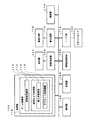
図1に、本実施形態を業務用ゲーム装置に適用した場合の例を示す。
【0021】
プレーヤは、シート1040に座り、画面1050に映し出されたゲーム画像を見ながら、ステアリング1052、アクセル1054、ブレーキ1056を操作する。そして、プレーヤがステアリング1052を操舵すると、画面1050に映し出されている車(オブジェクト空間内の移動体)1060が左右にコーナリングする。また、プレーヤがアクセル1054やブレーキ1056を操作すると、車1060が加速したり減速したりする。そしてプレーヤは、このように車1060を操作し、シート1042、1044、1046に座る他のプレーヤが操作する車や、コンピュータが操作する車と順位やラップタイムを競い合い、競争ゲームを楽しむ。
【0022】
なお、CCDカメラ(撮影手段)1062は、プレーヤの顔画像(プレーヤ識別画像)を撮影するためのものである。CCDカメラ1062により撮影された顔画像を、そのプレーヤが操作する車に関連づけることで、どのプレーヤがどの車を操作しているかを容易に認識できるようになる。また、中継用ディスプレイ1064には、ゲームに参加しない第三者がマルチプレーヤゲームの様子を観戦したり、プレーヤが運転した車の走行の様子をリプレイするための、中継画面1066が表示される。また、スロット1072は、メモリーカード(携帯型情報記憶装置)1070を挿入するためのものである。このメモリーカード1070は家庭用ゲーム装置でも使用可能になっており、このメモリカード1070を介して、業務用ゲーム装置、家庭用ゲーム装置間での情報交換が可能になる。
【0023】
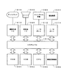
図2に、本実施形態のブロック図の一例を示す。なお同図において本実施形態は、少なくとも処理部100を含めばよく(或いは処理部100と記憶部140、或いは処理部100と記憶部140と情報記憶媒体150を含めばよく)、それ以外のブロック(例えば操作部130、画像生成部160、表示部162、音生成部170、音出力部172、通信部174、I/F部176、メモリーカード180等)については、任意の構成要素とすることができる。
【0024】
ここで処理部100は、装置全体の制御、装置内の各ブロックへの命令の指示、ゲーム演算などの各種の処理を行うものであり、その機能は、CPU(CISC型、RISC型)、DSP、或いはASIC(ゲートアレイ等)などのハードウェアや、所与のプログラム(ゲームプログラム)により実現できる。
【0025】
操作部130は、プレーヤが操作情報を入力するためのものであり、その機能は、図1のステアリング1052、アクセル1054、ブレーキ1056、操作ボタンなどのハードウェアにより実現できる。
【0026】
記憶部140は、処理部100、画像生成部160、音生成部170、通信部174、I/F部176などのワーク領域となるもので、その機能はRAMなどのハードウェアにより実現できる。
【0027】
情報記憶媒体(コンピュータにより使用可能な記憶媒体)150は、プログラムやデータなどの情報を格納するものであり、その機能は、光ディスク(CD、DVD)、光磁気ディスク(MO)、磁気ディスク、ハードディスク、磁気テープ、或いは半導体メモリ(ROM)などのハードウェアにより実現できる。処理部100は、この情報記憶媒体150に格納される情報に基づいて本発明(本実施形態)の種々の処理を行う。即ち情報記憶媒体150には、本発明(本実施形態)の手段(特に処理部100に含まれるブロック)を実現するための種々の情報が格納される。
【0028】
なお、情報記憶媒体150に格納される情報の一部又は全部は、装置への電源投入時等に記憶部140に転送されることになる。また情報記憶媒体150に記憶される情報は、本発明の処理を行うためのプログラムコード、画像情報、音情報、表示物の形状情報、テーブルデータ、リストデータ、プレーヤ情報や、本発明の処理を指示するための情報、その指示に従って処理を行うための情報等の少なくとも1つを含むものである。
【0029】
画像生成部160は、処理部100からの指示等にしたがって、各種の画像を生成し表示部162に出力するものであり、その機能は、画像生成用ASIC、CPU、或いはDSPなどのハードウェアや、所与のプログラム(画像生成プログラム)、画像情報により実現できる。
【0030】
音生成部170は、処理部100からの指示等にしたがって、各種の音を生成し音出力部172に出力するものであり、その機能は、音生成用ASIC、CPU、或いはDSPなどのハードウェアや、所与のプログラム(音生成プログラム)、音情報(波形データ等)により実現できる。
【0031】
通信部174は、外部装置(例えばホスト装置や他のゲーム装置)との間で通信を行うための各種の制御を行うものであり、その機能は、通信用ASIC、或いはCPUなどのハードウェアや、所与のプログラム(通信プログラム)により実現できる。
【0032】
なお本発明(本実施形態)の処理を実現するための情報は、ホスト装置が有する情報記憶媒体からネットワーク、通信部174を介してゲーム装置(広義には画像生成装置)が有する情報記憶媒体に配信するようにしてもよい。このようなホスト装置の情報記憶媒体の使用やゲーム装置の情報記憶媒体の使用も本発明の範囲内に含まれる。
【0033】
また処理部100の機能の一部又は全部を、画像生成部160、音生成部170、又は通信部174の機能により実現するようにしてもよい。或いは、画像生成部160、音生成部170、又は通信部174の機能の一部又は全部を、処理部100の機能により実現するようにしてもよい。
【0034】
I/F部176は、処理部100からの指示等にしたがってメモリーカード(広義には、携帯型ミニゲーム装置などを含む携帯型情報記憶装置)180との間で情報交換を行うためのインターフェースとなるものであり、その機能は、メモリーカードを挿入するためのスロットや、データ書き込み・読み出し用コントローラICなどにより実現できる。なお、メモリーカード180との間の情報交換を赤外線などの無線を用いて実現する場合には、I/F部176の機能は、半導体レーザ、赤外線センサーなどのハードウェアにより実現できる。
【0035】
処理部100は、ゲーム演算部110を含む。
【0036】
ここでゲーム演算部110は、コイン(代価)の受け付け処理、ゲームモードの設定処理、ゲームの進行処理、選択画面の設定処理、移動体(車等)の位置や方向を決める処理、視点位置や視線方向を決める処理、移動体のモーションを再生する処理、オブジェクト空間へオブジェクトを配置する処理、ヒットチェック処理、ゲーム成果(成績)を演算する処理、複数のプレーヤが共通のゲーム空間でプレイするための処理、或いはゲームオーバー処理などの種々のゲーム演算処理を、操作部130からの操作情報、メモリーカード180からの情報、ゲームプログラムなどに基づいて行う。なお、本発明を車ゲーム以外のゲームに適用した場合には、移動体としては、キャラクタ、バイク、飛行機、船、水上スキー、サーフボード、戦車、ロボット、宇宙船等、種々のものを考えることができる。
【0037】
ゲーム演算部110は、移動体演算部112、仮想カメラ制御部114を含む。
【0038】
ここで移動体演算部112は、車などの移動体の移動情報(位置情報、方向情報等)を演算するものであり、例えば操作部130から入力される操作情報や所与のプログラムに基づき、移動体をオブジェクト空間内で移動させる演算などを行う。即ち、プレーヤ(自プレーヤ、他プレーヤ)による操作、或いはコンピュータ(所与の移動制御アルゴリズム)による操作等に基づいて、移動体をオブジェクト空間内で移動させる演算などを行う。
【0039】
より具体的には、移動体演算部112は、移動体の位置や方向を例えば1フレーム(1/60秒)毎に求める処理を行う。例えば(k−1)フレームでの移動体の位置をPMk-1、速度をVMk-1、加速度をAMk-1、1フレームの時間を△tとする。するとkフレームでの移動体の位置PMk、速度VMkは例えば下式(1)、(2)のように求められる。
【0040】
PMk=PMk-1+VMk-1×△t (1)
VMk=VMk-1+AMk-1×△t (2)
仮想カメラ制御部114は、オブジェクト空間内の所与(任意)の視点での画像を生成するための仮想カメラを制御する処理を行う。即ち、仮想カメラの所与の軸(例えばX、Y、Z軸)回りでの回転や仮想カメラの位置を制御する処理(視点位置や視線方向を制御する処理)等を行う。
【0041】
例えば、仮想カメラにより移動体を後方から撮影する場合には、移動体の位置の変化や方向の変化に仮想カメラが追従するように、仮想カメラの軸回り回転(仮想カメラの方向)や仮想カメラの位置を制御する処理を行う。この場合、移動体演算部112で得られた移動体の位置、方向又は速度などの情報に基づいて、仮想カメラを制御することになる。
【0042】
一方、優秀プレーヤの移動体の走行をリプレイするリプレイモード時においては、仮想カメラ制御部114は、まず、コース沿い(コース脇)に設定された複数の仮想カメラの中から、撮影対象となる移動体に近い仮想カメラを選択する。そして、選択された仮想カメラを、撮影対象となる移動体の位置、方向又は速度などの情報に基づいて制御しながら、その仮想カメラにより、撮影対象となる移動体を撮影する。この場合、通常のゲームプレイ中における移動体の位置、方向又は速度などの情報(広義には、移動体の移動を再現するための情報であり、移動体の操作情報でもよい)を記憶部に蓄積しておく。そして、リプレイモード時では、この蓄積された情報に基づいて、移動体の走行(移動)をリプレイするようにする。
【0043】
仮想カメラ制御部114は、揺らぎ(振動)設定部116、オフセット値制御部118を含む。
【0044】
ここで、揺らぎ設定部116は、例えばオブジェクト空間内で移動する移動体を追うために、仮想カメラの所与の軸(例えばX、Y又はZ軸)回りでの回転、或いは仮想カメラの位置が変化した場合に、仮想カメラに揺らぎを与えるための処理(仮想カメラを振動させるための処理)、即ち、仮想カメラの所与の軸回りでの回転や仮想カメラの位置に対して揺らぎを与えるための処理を行う。
【0045】
より具体的には、仮想カメラの回転角速度(回転変化量)、或いは仮想カメラの速度(位置変化量)に応じた揺らぎを、仮想カメラに与えるようにする。例えば、上記回転角速度、上記速度に基づいて、仮想カメラに揺らぎを与えるか否かを判断したり、上記回転角速度、上記速度によりその大きさが決まる揺らぎを仮想カメラに与えるようにする。
【0046】
この場合、例えば、仮想カメラの回転角速度が速いほど広くなる、或いは仮想カメラの速度が速いほど広くなる揺らぎ範囲を求め、この揺らぎ範囲内に入るような揺らぎを、揺らぎ関数や揺らぎ値テーブルに基づいて求め、仮想カメラに与えるようにすることが望ましい。
【0047】
また、揺らぎ設定部116は、仮想カメラの回転角速度が所与の回転角速度より大きい場合、或いは仮想カメラの速度が所与の速度より大きい場合に、揺らぎをリミット値に設定する処理(広義には、揺らぎの増加を制限する処理)も行う。
【0048】
オフセット値制御部118は、移動体位置と仮想カメラの注視点位置との間のオフセット値を可変に制御する処理を行う。即ち、このオフセット値を可変に制御しながら、オブジェクト空間内を移動する移動体に仮想カメラの注視点を追従させる。このようにすれば、移動体を画面中心から任意の位置にずらしながら、移動体を仮想カメラで追うことが可能になり、ゲーム演出のバラエティ度を増すことができるようになる。そして、この場合、移動体を仮想カメラで追うことで、仮想カメラの軸回り回転や位置が変化すると、その変化量に応じた揺らぎが仮想カメラに与えられることになる。
【0049】
なお、上記オフセット値は、例えば移動体からの距離(仮想カメラと移動体の距離、プレーヤ移動体と移動体との距離等)に基づいて変化させてもよいし、移動体の速度に基づいて変化させてもよいし、他の要因に基づいて変化させてもよい。
【0050】
なお、本実施形態は、1人のプレーヤがプレイするシングルプレーヤモードによるゲームプレイと、複数のプレーヤがプレイするマルチプレーヤモードによるゲームプレイの両方が可能になっている。
【0051】
また複数のプレーヤがプレイする場合に、これらの複数のプレーヤに提供する画像や音を、1つのゲーム装置(広義には画像生成装置)を用いて生成してもよいし、ネットワーク(伝送ライン、通信回線)などで接続された複数のゲーム装置を用いて生成してもよい。
【0052】
2.本実施形態の特徴
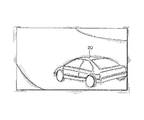
図3(A)、(B)に、本実施形態により生成される画像の例を示す。
【0053】
図3(A)、(B)は、リプレイモード(アトラクトモードの1つ)時に生成される画像の例である。即ち、本実施形態では、プレーヤが優秀な成績を残した場合に、ゲーム終了後、そのプレーヤが運転した車の走行の様子をプレーヤに見せるために、リプレイ画像を表示する。このリプレイ画像は、コース沿いに設定されたリプレイ用の仮想カメラから見える画像である。即ち、本実施形態ではコースに沿って複数のリプレイ用の仮想カメラが設置されている。そして、プレーヤの車の位置に基づいて、これらの複数のリプレイ用の仮想カメラの中から1つの仮想カメラが選択され、この仮想カメラにより、プレーヤの車の走行の様子が撮影される。
【0054】
図3(A)、(B)では、図4(A)に示すようにコース上を移動する移動体(車)20を、仮想カメラ30が追っている(移動体に仮想カメラの注視点を追従させている)。このため、仮想カメラ30が所与の軸回りで回転している。この場合に本実施形態では、図4(A)に示すように仮想カメラ30に対して揺らぎが与えられる。また、図4(B)では、移動体20を追うために仮想カメラ30の位置が変化しており、この場合にも本実施形態では、仮想カメラ30に対して揺らぎが与えられる。より具体的には、図4(C)に示すように、仮想カメラ30のX軸、Y軸又はZ軸回りでの回転(回転角)α、β、γ、或いは仮想カメラ30の位置PCが変化すると、これらのα、β、γ、或いはPCに対して揺らぎが与えられる。これにより、図3(A)、(B)に示すように画面が揺らぐようになり、あたかも、移動体20を追うことによる手ぶれにより仮想カメラ30が振動したかのような錯覚をプレーヤに与えることができる。この結果、画像の臨場感やリアル度を格段に高めることができるようになる。
【0055】
即ち、コース上で移動する移動体を仮想カメラで撮る場合、移動体と仮想カメラを結ぶベクトルを求め、このベクトルの方向に仮想カメラを向ける手法が考えられる。この手法によれば、図4(A)のように移動体が移動しても、常に画面内に移動体が入るようになり、移動体の走行の様子を確実にプレーヤに見せることができるようになる。
【0056】
しかしながら、この手法では、画面中心に移動体が常に固定されてしまい、いかにもコンピュータ制御の仮想カメラで撮ったというような単調な画像が生成されてしまう。
【0057】
これに対して本実施形態では、移動体を追うために、仮想カメラが所与の軸回りで回転したりその位置が変化すると、仮想カメラに揺らぎが与えられる。従って、いかにもコンピュータ制御の仮想カメラで撮ったというような画像が生成されることが防止され、実際の人間が本当のカメラで撮ったかのように見える画像を生成できるようになる。しかも、本実施形態によれば、現実の人間の手ぶれを忠実にシミュレーションすることなく、手ぶれによる仮想カメラの揺らぎをプレーヤに擬似的に体感させることができる。即ち、少ない処理負担で、よりリアルな画像を生成することに成功している。
【0058】
さて、本実施形態では、仮想カメラの回転角速度(仮想カメラの所与の軸回りでの回転の変化量)又は仮想カメラの速度(仮想カメラの位置の変化量)に応じた揺らぎを、仮想カメラ(仮想カメラの軸回り回転、位置)に与えるようにしている。
【0059】
例えば図5(A)、(B)に示すように、仮想カメラ30の回転角速度が速い場合には仮想カメラの30の揺らぎを大きくし、回転角速度が遅い場合には揺らぎを小さくする。
【0060】
また図5(C)、(D)に示すように、仮想カメラ30の速度が速い場合には仮想カメラの30の揺らぎを大きくし、速度が遅い場合には揺らぎを小さくする。
【0061】
例えば、いわゆるCGムービーでは、仮想カメラの回転角速度や仮想カメラの速度は全く考慮されない。従って、回転角速度の大小、速度の大小に依らずに、画一的な画像が表示されることになる。
【0062】
これに対して本実施形態では、回転角速度の大小、速度の大小に応じて、生成される画像が異なって見えるようになる。即ち、あるプレーヤの走行リプレイ時における仮想カメラの揺れ(ぶれ)と、他のプレーヤの走行リプレイ時における仮想カメラの揺れとは異なったものになり、生成されるリプレイ画像も異なって見えるようになる。
【0063】
例えば、上級プレーヤが運転する移動体(車)は、一般的に、仮想カメラの配置場所を、より速い速度で通過する。従って、この高速走行する移動体を追う仮想カメラの回転角速度や速度も速くなる。従って、仮想カメラの揺れも大きくなる。そして、そのリプレイ画像を見たプレーヤは、仮想カメラの大きな揺れを通して、自身が運転した移動体のスピード感を感じ取ることができるようになる。
【0064】
このように図5(A)〜(D)の手法を採用することで、本実施形態では、生成される画像のバラエティ度、リアル度を格段に増すことに成功している。
【0065】
なお、図5(A)〜(D)において、仮想カメラ30の回転角速度そのもの、或いは速度そのものではなく、上記回転角速度と均等なパラメータ、或いは上記速度と均等なパラメータに基づいて仮想カメラ30の揺らぎを制御する場合も本発明の範囲に含まれる。例えば仮想カメラ30の相対的な回転角速度、或いは相対的な速度に基づいて仮想カメラ30の揺らぎを制御してもよい。
【0066】
また、本実施形態では、仮想カメラの回転角速度又は速度に応じて変化する揺らぎ範囲を求め、この揺らぎ範囲内の揺らぎを仮想カメラに与えるようにしている。
【0067】
例えば図6(A)に示すように、仮想カメラ30の回転角速度が速い場合には、仮想カメラ30の揺らぎ範囲40を大きくする。また、仮想カメラ30の速度が速い場合にも、仮想カメラ30の揺らぎ範囲40を大きくする。
【0068】
一方、図6(B)に示すように、仮想カメラ30の回転角速度が遅い場合には、仮想カメラ30の揺らぎ範囲40を小さくする。また、仮想カメラ30の速度が遅い場合にも、仮想カメラ30の揺らぎ範囲40を小さくする。
【0069】
このように図6(A)、(B)では、仮想カメラの回転角速度や速度に応じて、揺らぎ範囲を決める。そして、この範囲内に入るような揺らぎを、揺らぎ関数や揺らぎ値テーブルに基づいて求める。このようにすれば、仮想カメラの回転角速度や速度に応じて変化する仮想カメラの揺らぎを、簡易な処理で実現できるようになる。
【0070】
なお揺らぎ範囲としては、例えば、仮想カメラの軸回り回転の揺らぎ範囲、仮想カメラの位置の揺らぎ範囲、又は仮想カメラが向く方向の立体角の揺らぎ範囲などを考えることができる。
【0071】
また本実施形態では、図7に示すように、仮想カメラ30の回転角速度が上限値ωLMより大きい場合に、仮想カメラ30の揺らぎの増加(揺らぎ範囲の拡大)を制限している(例えばリミット値に設定する)。また、仮想カメラ30の速度が上限値VLMより大きい場合にも、揺らぎの増加を制限している。
【0072】
このようにすれば、例えば仮想カメラの回転角速度や速度が非常に大きくなった場合にも、仮想カメラの揺らぎが過大になるのを防止できる。これにより、プレーヤに不自然感を与える事態を効果的に防止できるようになる。
【0073】
さて、本実施形態では、仮想カメラが移動体を追う際に、移動体位置と仮想カメラの注視点位置との間のオフセット値(オフセット距離等)を可変に制御できるようになっている。
【0074】
即ち、図8(A)では、コース上を移動する移動体20を仮想カメラ30が追っている(注視点を移動体に追従させている)。この際に本実施形態では、図8(B)に示すように、移動体20の位置(例えば代表点の位置)PMと、仮想カメラ30の注視点(注目点)の位置PGとの間のオフセット値が可変に制御される。
【0075】
例えば図3(A)のゲーム画像では、注視点位置PGと移動体位置PMがほぼ一致しており(図8(B)の零オフセット)、移動体20は画面中心付近に表示されている。そして、図3(B)のゲーム画像では、オフセット値が変化し、PGがPMの後ろにくるようなる(図8(B)のマイナスオフセット)。この結果、移動体20は画面中心よりも前に表示されるようになる。
【0076】
また図9(A)のゲーム画像では、PGとPMがほぼ一致しており、移動体20は画面中心付近に表示されている。そして、図9(B)、図10のゲーム画像では、オフセット値が変化し、PGがPMの前にくるようになる(図8(B)のプラスオフセット)。この結果、移動体20は画面中心よりも後ろに表示されるようになる。
【0077】
このようにPM、PG間のオフセット値を可変に制御することで、ゲーム画像のバラエティ度を格段に増すことができるようになる。
【0078】
即ち、仮想カメラに移動体を追わせる第1の手法として、仮想カメラと移動体を結ぶ第1のベクトルの方向に仮想カメラを向ける手法が考えられる。しかしながら、この第1の手法では、移動体は常に画面中心付近に表示されるようになり、得られる画像が、いかにもコンピュータ制御の仮想カメラで撮ったというような単調な画像になるという問題がある。
【0079】
このような問題を解決する第2の手法として、仮想カメラと移動体を結ぶ第1のベクトルよりも少し遅れてその向きが変化する第2のベクトルを求め、この第2のベクトルの方向に仮想カメラを向ける手法も考えられる。しかしながら、この第2の手法では、移動体は常に画面中心よりも前に表示されるようになり、得られる画像が単調になる。
【0080】
本実施形態によれば、図8(B)に示すように、移動体20を仮想カメラ30が追う際にPM、PG間のオフセット値を可変に制御できる。従って、図3(A)、(B)に示すように、移動体20が遠くにある時には移動体20を画面中心付近に表示し、移動体20が仮想カメラの前を通り過ぎる時には移動体を画面中心よりも前に表示することができるようになる。これにより、移動体が高速で走行したがために仮想カメラの追従が遅れたかのような錯覚をプレーヤに与えることが可能になり、得られる画像のリアル度を増すことができる。
【0081】
また本実施形態によれば、図9(A)、(B)、図10に示すように、移動体20が遠くにある時には移動体20を画面中心付近に表示し、移動体20が仮想カメラの前を通り過ぎる時には移動体20を画面中心よりも後ろに表示することができるようになる。これにより、移動体20の先にあるカーブをプレーヤに見せる等の演出が可能になり、ゲーム演出のバラエティ度を増すことができる。
【0082】
なお、移動体位置と注視点位置の間のオフセット値としては、オブジェクト空間内の3次元的な距離、画面上の2次元的な距離、仮想カメラ・移動体間を結ぶ方向と仮想カメラ・注視点間を結ぶ方向とのなす角度、或いは、これらの距離、角度と均等なパラメータ等、種々のものを考えることができる。
【0083】
また、オフセット値は、移動体からの距離(移動体と仮想カメラの距離、移動体と仮想カメラの付近にある移動体との距離、或いは奥行き距離等)に基づいて制御することもできるし、移動体の速度(絶対速度、相対速度)に基づいて制御することもできる。
【0084】
例えば図11(A)、(B)では、移動体20と仮想カメラ30の距離が遠い場合にはオフセット値を零(或いはほぼ零)に設定し、距離が近い場合にはオフセット値をマイナスに設定している。このようにすれば図3(A)、(B)に示すように、移動体20が遠く離れている場合には移動体20が画面中心に表示され、移動体20が近づくと画面中心よりも前に表示されるようになる。これにより、移動体20が高速で走行しているがために仮想カメラの追従が遅れたかのような錯覚をプレーヤに与えることができ、スピード感のある画像を生成できるようになる。そして、この場合に、移動体20の速度が速いほどオフセット値を大きくすれば、得られる画像のスピード感を更に増すことができるようになる。
【0085】
また図12(A)、(B)では、移動体20と仮想カメラ30の距離が遠い場合にはオフセット値を零(或いはほぼ零)に設定し、距離が近い場合にはオフセット値をプラスに設定している。このようにすれば図9(A)、(B)、図10に示すように、移動体20が遠く離れている場合には移動体20が画面中心に表示され、移動体20が近づくと画面中心よりも後ろに表示されるようになる。これにより、移動体20の先にあるコースをプレーヤに見せること等が可能になり、効果的なゲーム演出が可能になる。
【0086】
なお、オフセット値(或いはオフセット値を特定するための情報)を、オブジェクト空間内のマップに設定しておくようにしてもよい。より具体的には、オフセット値を、オブジェクト空間内のコース(広義にはマップ)を分割するコースブロックに関連づけて登録しておく。そして、移動体が位置するコースブロックを検索し、検索されたコースブロックに関連づけて登録されたオフセット値を用いて、仮想カメラを制御するようにする。
【0087】
例えば、図13(A)では、オブジェクト空間内のコース50を複数のコースブロックC0〜C1024に分割している。コース50は、道のり距離で例えば1m間隔毎にコースブロックに分割される。そして図13(B)において、移動体20がコースブロックCj内に位置するか否かを、ライン52、54の配置情報により判定する。そして、移動体20が位置するコースブロックを特定することで、移動体20の順位を決めたり時間延長の可否を決めている。例えば第1の移動体がコースブロックC18に位置し、それを追いかける第2の移動体がコースブロックC17に位置した場合には、第1、第2の移動体の順位を、各々、1位、2位と判断する。また所与の時間内に、あるコースブロックを通過したか否かを判定し、通過した場合にはそのプレーヤのプレイ時間を延長する。
【0088】
このようにコース50を複数のコースブロックに分割した場合に、図14に示すように、各コースブロックに関連づけてオフセット値を登録(設定)しておく。即ち、コースブロックC0、C1、C2・・・・に対して、その各コースブロックでのオフセット値OFF0、OFF1、OFF2・・・・を登録しておく。そして、移動体20がコースブロックC0、C1、C2・・・に位置すると判断した場合には、各々、オフセット値OFF0、OFF1、OFF2を用いて仮想カメラを制御するようにする。
【0089】
このようにすれば、コースの各場所に適したオフセット値で仮想カメラを制御できるようになるため、ゲーム演出のバラエティ度を更に増すことができるようになる。例えば、コースの第1の場所では、距離に依らずにオフセット値を常にマイナスにし、第2の場所では、距離に依らずにオフセット値を常にプラスにすることなども可能になる。
【0090】
また、移動体が仮想カメラを右から左に通り過ぎる場合を考える。この場合に、オフセット値をコースブロックに登録する手法によれば、移動体が仮想カメラの右に位置する場合にはオフセット値を零に設定し、移動体が仮想カメラの前に来た場合にはオフセット値をプラスに設定し、左へ通り過ぎた場合にも、そのままオフセット値をプラスに設定する等のゲーム演出が可能になる。
【0091】
3.本実施形態の処理
次に、本実施形態の詳細な処理例について図15、図16のフローチャートを用いて説明する。
【0092】
まず図17に示すように、移動体20からの距離DMCと移動体20の速度VMを得る(ステップS1)。そして、これらの距離DMC、速度VMに基づいて、オフセット値ベクトルVOFFを求める(ステップS2)。
【0093】
次に、移動体20の位置(例えば代表点の位置)PMとオフセット値ベクトルVOFFに基づいて、注視点(注目点)の位置PGを求める(ステップS3)。そして、仮想カメラ30の位置(視点位置)PCからPGへと向かう注視点方向単位ベクトルEOFFを求める(ステップS4)。
【0094】
次に、前のフレームでの注視点方向単位ベクトルEOFFと、当該フレームでの注視点方向単位ベクトルEOFFとの差分(差分ベクトル)の絶対値に基づき、仮想カメラ30の回転角速度パラメータNωを求める(ステップS5)。このNωは、仮想カメラ30の揺らぎ範囲(図6(A)、(B)参照)を設定するパラメータになる。
【0095】
なお、ステップS2で求められるオフセット値ベクトルVOFFの方向は、移動体20の移動方向に基づいて決めてもよいし、前のフレームでの注視点方向単位ベクトルEOFFの方向(EOFFに直交する方向)に基づいて決めてもよい。
【0096】
次に、回転角速度パラメータNωが、リミット値ωLMよりも大きいか否かを判断し(ステップS6)、大きい場合には、図18(A)に示すように、Nωをリミット値ωLMに設定する(ステップS7)。このようにすることで、図7で説明したように、NωがωLMより大きい場合には、仮想カメラの揺らぎを制限できるようになる。従って、仮想カメラの回転角速度が非常に大きくなった場合に、仮想カメラの揺らぎが過大になるのを防止できるようになる。
【0097】
次に、仮想カメラの速度に基づいて、仮想カメラの速度パラメータNVを求める(ステップS8)。このNVは、仮想カメラ30の揺らぎ範囲(図6(A)、(B)参照)を設定するパラメータになる。
【0098】
次に、速度パラメータNVが、リミット値VLMよりも大きいか否かを判断し(ステップS9)、大きい場合には、図18(B)に示すように、NVをリミット値VLMに設定する(ステップS10)。このようにすることで、図7で説明したように、NVがVLMより大きい場合には、仮想カメラの揺らぎを制限できるようになる。従って、仮想カメラの速度が非常に大きくなった場合に、仮想カメラの揺らぎが過大になるのを防止できるようになる。
【0099】
次に、パラメータNω、NVと揺らぎ関数FX、FYに基づいて、X軸、Y軸回りでの揺らぎ角度を求める(ステップS11)。ここで、揺らぎ関数FX、FYは、各々、X軸、Y軸回りの回転に関する揺らぎ関数である。
【0100】
このように揺らぎ角度θX、θYを決めることで、図6(A)、(B)で説明したように、仮想カメラの回転角速度又は速度が速いほど広くなる揺らぎ範囲を設定し、この揺らぎ範囲内での揺らぎを、仮想カメラに与えることが可能になる。即ち、X軸、Y軸回りの回転角の揺らぎ範囲は、パラメータNω、NVにより決められ、その揺らぎ範囲内で、揺らぎ角度θX、θYが変化するようになるからである。
【0101】
次に、揺らぎ角度θX、θYに基づいて、揺らぎ回転マトリクスMTθを求める(ステップS12)。
【0102】
次に、図15のステップS4で得られた注視点方向単位ベクトルEOFFに基づいて、仮想カメラの回転マトリクスMTCを求める(ステップS13)。そして、得られた回転マトリクスMTCに対して揺らぎ回転マトリクスMTθを掛ける(ステップS14)。そして、得られた回転マトリクスMTC=MTC×MTθに基づいて、仮想カメラを回転させる(ステップS15)。
【0103】
以上のようにすることで、仮想カメラの回転角速度や速度に応じた揺らぎを仮想カメラに与えることができるようになると共に、移動体位置と注視点位置の間のオフセット値を可変に制御できるようになる。
【0104】
4.ハードウェア構成
次に、本実施形態を実現できるハードウェアの構成の一例について図19を用いて説明する。同図に示す装置では、CPU1000、ROM1002、RAM1004、情報記憶媒体1006、音生成IC1008、画像生成IC1010、I/Oポート1012、1014が、システムバス1016により相互にデータ送受信可能に接続されている。そして前記画像生成IC1010にはディスプレイ1018が接続され、音生成IC1008にはスピーカ1020が接続され、I/Oポート1012にはコントロール装置1022が接続され、I/Oポート1014には通信装置1024が接続されている。
【0105】
情報記憶媒体1006は、プログラム、表示物を表現するための画像データ、音データ等が主に格納されるものである。例えば家庭用ゲーム装置ではゲームプログラム等を格納する情報記憶媒体としてDVD、CD−ROM、ゲームカセット、等が用いられる。また業務用ゲーム装置ではROM等のメモリが用いられ、この場合には情報記憶媒体1006はROM1002になる。
【0106】
コントロール装置1022はゲームコントローラ、操作パネル等に相当するものであり、プレーヤがゲーム進行に応じて行う判断の結果を装置本体に入力するための装置である。
【0107】
情報記憶媒体1006に格納されるプログラム、ROM1002に格納されるシステムプログラム(装置本体の初期化情報等)、コントロール装置1022によって入力される信号等に従って、CPU1000は装置全体の制御や各種データ処理を行う。RAM1004はこのCPU1000の作業領域等として用いられる記憶手段であり、情報記憶媒体1006やROM1002の所与の内容、あるいはCPU1000の演算結果等が格納される。また本実施形態を実現するための論理的な構成を持つデータ構造は、このRAM又は情報記憶媒体上に構築されることになる。
【0108】
更に、この種の装置には音生成IC1008と画像生成IC1010とが設けられていてゲーム音やゲーム画像の好適な出力が行えるようになっている。音生成IC1008は情報記憶媒体1006やROM1002に記憶される情報に基づいて効果音やバックグラウンド音楽等のゲーム音を生成する集積回路であり、生成されたゲーム音はスピーカ1020によって出力される。また、画像生成IC1010は、RAM1004、ROM1002、情報記憶媒体1006等から送られる画像情報に基づいてディスプレイ1018に出力するための画素情報を生成する集積回路である。なおディスプレイ1018として、いわゆるヘッドマウントディスプレイ(HMD)と呼ばれるものを使用することもできる。
【0109】
また、通信装置1024はゲーム装置内部で利用される各種の情報を外部とやりとりするものであり、他のゲーム装置と接続されてゲームプログラムに応じた所与の情報を送受したり、通信回線を介してゲームプログラム等の情報を送受することなどに利用される。
【0110】
そして図1〜図18(B)で説明した種々の処理は、プログラムやデータなどの情報を格納した情報記憶媒体1006、この情報記憶媒体1006からの情報等に基づいて動作するCPU1000、画像生成IC1010或いは音生成IC1008等によって実現される。なお画像生成IC1010、音生成IC1008等で行われる処理は、CPU1000あるいは汎用のDSP等によりソフトウェア的に行ってもよい。
【0111】
前述の図1のように本実施形態を業務用ゲーム装置に適用した場合には、装置に内蔵されるシステムボード(サーキットボード)1106には、CPU、画像生成IC、音生成IC等が実装される。そして、本実施形態(本発明)を実現(実行)するための種々の情報は、システムボード1106上の情報記憶媒体である半導体メモリ1108に格納される。以下、これらの情報を格納情報と呼ぶ。
【0112】
図20(A)に、本実施形態を家庭用のゲーム装置に適用した場合の例を示す。プレーヤはディスプレイ1200に映し出されたゲーム画像を見ながら、ゲームコントローラ1202、1204を操作してゲームを楽しむ。この場合、上記格納情報は、本体装置に着脱自在な情報記憶媒体であるDVD1206、メモリーカード1208、1209等に格納されている。
【0113】
図20(B)に、ホスト装置1300と、このホスト装置1300と通信回線(LANのような小規模ネットワークや、インターネットのような広域ネットワーク)1302を介して接続される端末1304-1〜1304-nとを含むシステムに本実施形態を適用した場合の例を示す。この場合、上記格納情報は、例えばホスト装置1300が制御可能な磁気ディスク装置、磁気テープ装置、半導体メモリ等の情報記憶媒体1306に格納されている。端末1304-1〜1304-nが、CPU、画像生成IC、音処理ICを有し、スタンドアロンでゲーム画像、ゲーム音を生成できるものである場合には、ホスト装置1300からは、ゲーム画像、ゲーム音を生成するためのゲームプログラム等が端末1304-1〜1304-nに配送される。一方、スタンドアロンで生成できない場合には、ホスト装置1300がゲーム画像、ゲーム音を生成し、これを端末1304-1〜1304-nに伝送し端末において出力することになる。
【0114】
なお、図20(B)の構成の場合に、本発明の処理を、ホスト装置と端末とで(サーバーを設ける場合にはホスト装置とサーバーと端末とで)分散して処理するようにしてもよい。また、本発明を実現するための上記格納情報を、ホスト装置の情報記憶媒体と端末の情報記憶媒体(或いはホスト装置の情報記憶媒体とサーバの情報記憶媒体と端末の情報記憶媒体)に分散して格納するようにしてもよい。
【0115】
また通信回線に接続する端末は、家庭用ゲーム装置であってもよいし業務用ゲーム装置であってもよい。そして、業務用ゲーム装置を通信回線に接続する場合には、業務用ゲーム装置との間で情報のやり取りが可能であると共に家庭用ゲーム装置との間でも情報のやり取りが可能な携帯型情報記憶装置(メモリーカード、携帯型ゲーム装置)を用いることが望ましい。
【0116】
なお本発明は、上記実施形態で説明したものに限らず、種々の変形実施が可能である。
【0117】
例えば、本発明のうち従属請求項に係る発明においては、従属先の請求項の構成要件の一部を省略する構成とすることもできる。また、本発明の1の独立請求項に係る発明の要部を、他の独立請求項に従属させることもできる。
【0118】
また、本実施形態では、リプレイ画像の生成に本発明を適用した場合について説明したが、本発明はゲームプレイ中の画像の生成にも当然に適用できる。例えば、ダンジョン内でキャラクタ(移動体)が宝物等を探して歩き回るゲームを考える。このようなゲームでは、キャラクタを追うために、仮想カメラが所与の軸回りで回転したり移動した場合に、仮想カメラに揺らぎを与えるようにする。また、キャラクタの位置とキャラクタを追う仮想カメラの注視点位置との間のオフセット値を、所与の条件により可変に制御するようにする。
【0119】
また、本実施形態では、移動体に仮想カメラの注視点を追従させるために、仮想カメラの軸回り回転や仮想カメラの位置が変化する場合について説明した。しかしながら、仮想カメラの軸回り回転や仮想カメラの位置が変化し仮想カメラに揺らぎが与えられる状況としては、このように仮想カメラが移動体を追う状況に限定されず、種々の状況を考えることができる。
【0120】
また、本実施形態では、仮想カメラの所与の軸回りでの回転や仮想カメラの位置に対して揺らぎを与える場合について説明したが、上記回転や上記位置と均等なものに揺らぎを与える場合も本発明の範囲に含まれる。
【0121】
また、オフセット値の制御手法も、図11〜図14で説明したものに限定されず、種々の変形実施が可能である。
【0122】
また本発明は車ゲーム以外にも種々のゲーム(飛行機ゲーム、宇宙船ゲーム、バイクゲーム、格闘ゲーム、ロボット対戦ゲーム、スポーツゲーム、競争ゲーム、シューティングゲーム、ロールプレイングゲーム、音楽演奏ゲーム、ダンスゲーム、クイズゲーム等)に適用できる。
【0123】
また本発明は、業務用ゲーム装置、家庭用ゲーム装置、多数のプレーヤが参加する大型アトラクション装置、シミュレータ、マルチメディア端末、画像生成装置、ゲーム画像を生成するシステム基板等の種々の画像生成装置に適用できる。
【図面の簡単な説明】
【図1】本実施形態を業務用ゲーム装置に適用した場合の構成例を示す図である。
【図2】本実施形態のブロック図の例である。
【図3】図3(A)、(B)は、本実施形態により生成される画像の例である。
【図4】図4(A)、(B)、(C)は、仮想カメラが所与の軸回りに回転したり移動した場合に仮想カメラに揺らぎを与える手法について説明するための図である。
【図5】図5(A)、(B)、(C)、(D)は、仮想カメラの回転角速度、速度に応じた揺らぎを仮想カメラに与える手法について説明するための図である。
【図6】図6(A)、(B)は、仮想カメラの回転角速度、速度に応じて揺らぎ範囲を変化させる手法について説明するための図である。
【図7】仮想カメラの揺らぎをリミット値に制限する手法について説明するための図である。
【図8】図8(A)、(B)は、移動体位置と注視点位置のオフセット値を可変に制御しながら、仮想カメラに移動体を追わせる手法について説明するための図である。
【図9】図9(A)、(B)は、本実施形態により生成される画像の例である。
【図10】本実施形態により生成される画像の例である。
【図11】図11(A)、(B)は、移動体からの距離に基づいてオフセット値を制御する手法について説明するための図である。
【図12】図12(A)、(B)も、移動体からの距離に基づいてオフセット値を制御する手法について説明するための図である。
【図13】図13(A)、(B)は、コースブロックを利用する手法について説明するための図である。
【図14】コースブロックに関連づけてオフセット値を登録する手法について説明するための図である。
【図15】本実施形態の詳細な処理例を示すフローチャートの一例である。
【図16】本実施形態の詳細な処理例を示すフローチャートの一例である。
【図17】本実施形態の詳細な処理について説明するための図である。
【図18】図18(A)、(B)は、回転角速度パラメータNω、速度パラメータNVについて説明するための図である。
【図19】本実施形態を実現できるハードウェアの構成の一例を示す図である。
【図20】図20(A)、(B)は、本実施形態が適用される種々の形態の装置の例を示す図である。
【符号の説明】
20 移動体
30 仮想カメラ
40 揺らぎ範囲
50 コース
100 処理部
110 ゲーム演算部
112 移動体演算部
114 仮想カメラ制御部
116 揺らぎ設定部
118 オフセット値制御部
130 操作部
140 記憶部
150 情報記憶媒体
160 画像生成部
162 表示部
170 音生成部
172 音出力部
174 通信部
176 I/F部
180 メモリーカード[0001]
BACKGROUND OF THE INVENTION
The present invention relates to an image generation device and an information storage medium.
[0002]
[Background Art and Problems to be Solved by the Invention]
Conventionally, there has been known an image generation device (game device in a narrow sense) that arranges a plurality of objects in an object space that is a virtual three-dimensional space and generates an image that can be viewed from the viewpoint of a virtual camera. It is popular as a way to experience reality. Taking an image generation apparatus that can enjoy a racing game as an example, a player travels a vehicle (own vehicle) that the player drives in the object space, and a vehicle (other vehicle) that another player or computer drives. Enjoy the game by competing.
[0003]
Now, in such an image generation apparatus, it is an important technical problem to generate a more realistic image in order to improve the player's virtual reality.
[0004]
However, in such an image generation apparatus, the computer that actually controls the virtual camera is a computer, so the image seen from the virtual camera is different from the image taken by a human in the real world. It must be a thing. Accordingly, the obtained image is still monotonous and lacks realism.
[0005]
For example, when a car (moving body) driven by a player is taken by a virtual camera installed along a course, a method of obtaining a vector connecting the car and the virtual camera and directing the virtual camera in the direction of the vector can be considered. According to this method, even if the car moves at a high speed, the virtual camera can follow the car and the car surely enters the screen.
[0006]
However, with this method, the car is always fixed at the center of the screen, and an image as if taken with a computer-controlled virtual camera is generated. Therefore, the virtual reality of the player could not be improved.
[0007]
The present invention has been made to solve the above-described problems, and an object of the present invention is to provide an image generation apparatus capable of making an image seen from a virtual camera a more realistic image with a small processing load, and An object is to provide an information storage medium.
[0008]
[Means for Solving the Problems]
In order to solve the above-described problems, the present invention provides an image generation apparatus for generating an image, a unit for controlling a virtual camera for generating an image at a given viewpoint in an object space, and a virtual Means for fluctuating at least one of rotation of the virtual camera and / or the position of the virtual camera when at least one of rotation and / or position of the virtual camera of the camera changes And means for generating an image visible from the virtual camera. An information storage medium according to the present invention is an information storage medium that can be used by a computer, and includes information (program) for realizing (executing) the above means. The program according to the present invention is a program that can be used by a computer, and is a program for realizing (executing) the above means.
[0009]
According to the present invention, when the virtual camera rotates around a given axis or moves (changes in position), fluctuation is applied to the rotation or position around the axis of the virtual camera. Then, an image that can be seen from the virtual camera given the fluctuation is generated. Therefore, according to the present invention, it is possible to give the operator (player) the illusion that the virtual camera has vibrated due to camera shake, and the realism and realism of the image can be greatly increased. .
[0010]
The image generating apparatus, the information storage medium, and the program according to the present invention also provide a rotation of a virtual camera around a given axis and a virtual camera in order to cause a moving object that moves in an object space to follow a gazing point of the virtual camera. When at least one of the positions is changed, the virtual camera is rotated about a given axis and at least one of the positions of the virtual camera is fluctuated. According to the present invention, the moving body moves in the object space based on the operation by the operator, the operation by the computer, or information for reproducing the movement of the moving body. Then, in order to cause the moving object to follow the gazing point of the virtual camera, when the virtual camera rotates around a given axis or the virtual camera moves, fluctuation is applied to the virtual camera. As a result, it is possible to increase the realism and presence of the image seen from the virtual camera that follows the moving body.
[0011]
The image generation apparatus, the information storage medium, and the program according to the present invention can cause fluctuations according to at least one of the rotation angular speed of the virtual camera and the speed of the virtual camera to rotate around the given axis of the virtual camera and the virtual camera. It is characterized by giving to at least one of the positions. In this way, based on the rotation angular velocity (rotational change amount) and speed (position change amount) of the virtual camera, it can be determined whether or not to shake the virtual camera, or based on the rotation angular velocity and the speed. For example, it is possible to give a fluctuating fluctuation to a virtual camera. As a result, a more realistic image can be generated with a small processing load.
[0012]
The image generation apparatus, information storage medium, and program according to the present invention obtain a fluctuation range that becomes wider as the rotational angular velocity of the virtual camera becomes faster or becomes wider as the speed of the virtual camera increases, and the fluctuation within the fluctuation range is It is characterized in that it is applied to at least one of rotation around a given axis of the virtual camera and position of the virtual camera. In this way, the virtual camera can be shaken within the fluctuation range that changes according to the rotational angular velocity and speed of the virtual camera. In this case, it is desirable to obtain the fluctuation given to the virtual camera based on a fluctuation function, a fluctuation value table, or the like.
[0013]
The image generating apparatus, information storage medium, and program according to the present invention increase fluctuation when the rotational angular velocity of the virtual camera is larger than a given rotational angular velocity or when the virtual camera velocity is larger than a given velocity. It is characterized by limiting. In this way, it is possible to effectively prevent a situation in which the fluctuation is excessively large due to the extremely high rotational angular velocity or speed of the virtual camera.
[0014]
The present invention is also an image generation apparatus for generating an image, comprising means for performing an operation for moving a moving body in an object space, and a virtual for generating an image at a given viewpoint in the object space. Means for controlling the camera; means for causing the moving point moving in the object space to follow the moving point of the virtual camera while variably controlling the offset value between the position of the moving object and the position of the point of interest of the virtual camera; And means for generating an image visible from a virtual camera. An information storage medium according to the present invention is an information storage medium that can be used by a computer, and includes information (program) for realizing (executing) the above means. The program according to the present invention is a program that can be used by a computer, and is a program for realizing (executing) the above means.
[0015]
According to the present invention, when the virtual camera follows the moving body, the offset value (two-dimensional distance, three-dimensional distance, angle, etc.) between the moving body position and the gazing point position is variably controlled. Accordingly, it is possible to generate an image in which the position of the moving body in the screen changes variously. As a result, the variety of images obtained can be increased, and various effects can be created.
[0016]
The image generating apparatus, the information storage medium, and the program according to the present invention also provide a rotation of a virtual camera around a given axis and a virtual camera in order to cause a moving object that moves in an object space to follow a gazing point of the virtual camera. When at least one of the positions is changed, the virtual camera is rotated about a given axis and at least one of the positions of the virtual camera is fluctuated. In this way, it is possible to generate an image with high variety in which the position of the moving body in the screen changes variously, and it is also possible to generate a realistic image in which camera shake is expressed.
[0017]
The image generation apparatus, information storage medium, and program according to the present invention are characterized in that the offset value is variably controlled based on at least one of the distance from the moving body and the speed of the moving body. In this way, a variety of images can be generated by a simple process of changing the offset value according to the distance from the moving body and the speed of the moving body.
[0018]
The image generation apparatus, information storage medium, and program according to the present invention are characterized in that the offset value or information for specifying the offset value is set in a map in the object space. In this way, an arbitrary offset value can be set at each location on the map, and a wide variety of images can be generated with a small processing load.
[0019]
DETAILED DESCRIPTION OF THE INVENTION
Hereinafter, preferred embodiments of the present invention will be described with reference to the drawings. In the following, a case where the present invention is applied to a car game will be described as an example. However, the present invention is not limited to this and can be applied to various games.
[0020]
1. Constitution
FIG. 1 shows an example in which the present embodiment is applied to an arcade game machine.
[0021]
The player sits on the
[0022]
The CCD camera (photographing means) 1062 is for photographing a player's face image (player identification image). By associating the face image captured by the
[0023]
FIG. 2 shows an example of a block diagram of the present embodiment. In this figure, the present embodiment may include at least the processing unit 100 (or may include the
[0024]
Here, the
[0025]
The operation unit 130 is for the player to input operation information, and the function can be realized by hardware such as the
[0026]
The
[0027]
An information storage medium (storage medium usable by a computer) 150 stores information such as programs and data, and functions thereof are an optical disk (CD, DVD), a magneto-optical disk (MO), a magnetic disk, and a hard disk. It can be realized by hardware such as a magnetic tape or a semiconductor memory (ROM). The
[0028]
Part or all of the information stored in the information storage medium 150 is transferred to the
[0029]
The
[0030]
The
[0031]
The
[0032]
Information for realizing the processing of the present invention (this embodiment) is transferred from the information storage medium of the host device to the information storage medium of the game device (image generation device in a broad sense) via the network and
[0033]
Further, part or all of the functions of the
[0034]
The I / F unit 176 is an interface for exchanging information with a memory card (in a broad sense, a portable information storage device including a portable mini game device) 180 according to an instruction from the
[0035]
The
[0036]
Here, the
[0037]
The
[0038]
Here, the moving body calculation unit 112 calculates movement information (position information, direction information, etc.) of a moving body such as a car. For example, based on operation information input from the operation unit 130 or a given program, Performs operations such as moving a moving object in the object space. In other words, based on an operation by a player (self player, other player) or an operation by a computer (a given movement control algorithm), an operation for moving the moving body in the object space is performed.
[0039]
More specifically, the moving body computing unit 112 performs a process for obtaining the position and direction of the moving body, for example, every frame (1/60 seconds). For example, assume that the position of the moving body in the (k-1) frame is PMk-1, the speed is VMk-1, the acceleration is AMk-1, and the time of one frame is Δt. Then, the position PMk and the speed VMk of the moving body in k frames are obtained, for example, by the following equations (1) and (2).
[0040]
PMk = PMk-1 + VMk-1 * .DELTA.t (1)
VMk = VMk-1 + AMk-1 * .DELTA.t (2)
The virtual camera control unit 114 performs a process of controlling the virtual camera for generating an image at a given (arbitrary) viewpoint in the object space. That is, a rotation of a virtual camera around a given axis (for example, X, Y, and Z axes), a process of controlling the position of the virtual camera (a process of controlling the viewpoint position and the line of sight), and the like are performed.
[0041]
For example, when shooting a moving object from behind with a virtual camera, the virtual camera rotates around its axis (the direction of the virtual camera) or the virtual camera so that the virtual camera follows changes in the position and direction of the moving object. The process which controls the position of is performed. In this case, the virtual camera is controlled based on information such as the position, direction, or speed of the moving object obtained by the moving object computing unit 112.
[0042]
On the other hand, in the replay mode in which the traveling of the moving body of the excellent player is replayed, the virtual camera control unit 114 first moves from the plurality of virtual cameras set along the course (side the course) to be photographed. Select a virtual camera that is close to your body. Then, while controlling the selected virtual camera based on information such as the position, direction, or speed of the moving object to be imaged, the moving object to be imaged is imaged by the virtual camera. In this case, information such as the position, direction, or speed of the moving body during normal game play (in a broad sense, information for reproducing movement of the moving body, which may be operation information of the moving body) is stored in the storage unit. Accumulate. In the replay mode, the traveling (movement) of the moving body is replayed based on the accumulated information.
[0043]
The virtual camera control unit 114 includes a fluctuation (vibration) setting unit 116 and an offset value control unit 118.
[0044]
Here, the fluctuation setting unit 116 rotates the virtual camera around a given axis (for example, the X, Y, or Z axis) or the position of the virtual camera in order to follow a moving body that moves in the object space, for example. When changing, a process to shake the virtual camera (process to vibrate the virtual camera), that is, to give a fluctuation to the rotation of the virtual camera around a given axis and the position of the virtual camera Perform the process.
[0045]
More specifically, a fluctuation corresponding to the rotation angular velocity (rotational change amount) of the virtual camera or the speed (position change amount) of the virtual camera is given to the virtual camera. For example, based on the rotation angular velocity and the speed, it is determined whether or not the virtual camera is fluctuated, and a fluctuation whose magnitude is determined by the rotation angular velocity and the speed is given to the virtual camera.
[0046]
In this case, for example, a fluctuation range that becomes wider as the rotation angular velocity of the virtual camera becomes faster or becomes wider as the speed of the virtual camera becomes higher is obtained. It is desirable to obtain and give to the virtual camera.
[0047]
Further, the fluctuation setting unit 116 sets a fluctuation to a limit value when the rotation angular velocity of the virtual camera is larger than a given rotation angular velocity or when the virtual camera speed is larger than a given velocity (in a broad sense, , Processing for limiting the increase in fluctuation).
[0048]
The offset value control unit 118 performs processing to variably control the offset value between the moving body position and the gazing point position of the virtual camera. That is, the gazing point of the virtual camera is caused to follow a moving body that moves in the object space while variably controlling the offset value. In this way, it becomes possible to follow the moving body with the virtual camera while shifting the moving body from the center of the screen to an arbitrary position, and the variety of game effects can be increased. In this case, if the rotation or position around the axis of the virtual camera changes by following the moving body with the virtual camera, a fluctuation corresponding to the amount of change is given to the virtual camera.
[0049]
The offset value may be changed based on, for example, the distance from the moving body (the distance between the virtual camera and the moving body, the distance between the player moving body and the moving body, etc.), or based on the speed of the moving body. It may be changed or may be changed based on other factors.
[0050]
In the present embodiment, both the game play in the single player mode played by one player and the game play in the multiplayer mode played by a plurality of players are possible.
[0051]
Further, when a plurality of players play, images and sounds to be provided to the plurality of players may be generated using one game device (image generating device in a broad sense), or a network (transmission line, It may be generated using a plurality of game devices connected via a communication line).
[0052]
2. Features of this embodiment
3A and 3B show examples of images generated by this embodiment.
[0053]
3A and 3B are examples of images generated in the replay mode (one of attract modes). In other words, in this embodiment, when a player leaves an excellent score, a replay image is displayed after the game is over in order to show the player how the car is driven by the player. This replay image is an image that can be seen from a virtual camera for replay set along the course. That is, in this embodiment, a plurality of replay virtual cameras are installed along the course. Based on the position of the player's car, one virtual camera is selected from the plurality of virtual cameras for replay, and the state of the player's car traveling is photographed by the virtual camera.
[0054]
3A and 3B, the
[0055]
That is, when a moving body moving on a course is taken with a virtual camera, a method for obtaining a vector connecting the moving body and the virtual camera and directing the virtual camera in the direction of the vector can be considered. According to this method, even if the moving body moves as shown in FIG. 4A, the moving body always enters the screen, so that it is possible to reliably show the player how the moving body is traveling. become.
[0056]
However, with this method, the moving body is always fixed at the center of the screen, and a monotonous image that is taken with a virtual camera controlled by a computer is generated.
[0057]
On the other hand, in the present embodiment, when the virtual camera rotates around a given axis or changes its position in order to follow the moving body, the virtual camera is shaken. Therefore, it is possible to prevent the generation of an image as if it was taken with a computer-controlled virtual camera, and to generate an image that looks as if it was taken by a real camera. In addition, according to the present embodiment, it is possible to cause the player to experience the fluctuation of the virtual camera due to camera shake in a pseudo manner without faithfully simulating actual human camera shake. That is, it has succeeded in generating a more realistic image with a small processing load.
[0058]
In the present embodiment, the virtual camera rotation angular velocity (amount of change in rotation about a given axis of the virtual camera) or a fluctuation corresponding to the speed of the virtual camera (amount of change in the position of the virtual camera) is calculated using the virtual camera. (Rotation and position around the virtual camera axis).
[0059]
For example, as shown in FIGS. 5A and 5B, when the rotation angular velocity of the
[0060]
Further, as shown in FIGS. 5C and 5D, when the speed of the
[0061]
For example, in a so-called CG movie, the rotational angular velocity of the virtual camera and the speed of the virtual camera are not considered at all. Accordingly, a uniform image is displayed regardless of the rotational angular velocity and the speed.
[0062]
On the other hand, in the present embodiment, the generated image looks different depending on the rotational angular velocity and the speed. That is, the shake (blurring) of the virtual camera at the time of running replay of a certain player is different from the shake of the virtual camera at the time of running replay of another player, and the generated replay image also looks different. .
[0063]
For example, a moving body (car) driven by an advanced player generally passes through a place where the virtual camera is arranged at a higher speed. Therefore, the rotational angular velocity and speed of the virtual camera that follows the moving body that travels at a high speed are also increased. Therefore, the shake of the virtual camera is also increased. Then, the player who sees the replay image can feel the speed of the moving object he / she has driven through the large shaking of the virtual camera.
[0064]
By adopting the methods of FIGS. 5A to 5D in this way, in this embodiment, the variety level and the real level of the generated image have been remarkably increased.
[0065]
5A to 5D, the fluctuation of the
[0066]
In the present embodiment, a fluctuation range that changes in accordance with the rotation angular velocity or speed of the virtual camera is obtained, and fluctuations within this fluctuation range are given to the virtual camera.
[0067]
For example, as shown in FIG. 6A, when the rotation angular velocity of the
[0068]
On the other hand, as shown in FIG. 6B, when the rotation angular velocity of the
[0069]
As described above, in FIGS. 6A and 6B, the fluctuation range is determined according to the rotational angular velocity and speed of the virtual camera. Then, a fluctuation that falls within this range is obtained based on a fluctuation function and a fluctuation value table. In this way, the fluctuation of the virtual camera that changes in accordance with the rotation angular velocity and speed of the virtual camera can be realized with a simple process.
[0070]
As the fluctuation range, for example, a fluctuation range of rotation around the axis of the virtual camera, a fluctuation range of the position of the virtual camera, or a fluctuation range of a solid angle in the direction in which the virtual camera faces can be considered.
[0071]
Further, in the present embodiment, as shown in FIG. 7, when the rotation angular velocity of the
[0072]
In this way, it is possible to prevent the fluctuation of the virtual camera from becoming excessive even when, for example, the rotational angular velocity or speed of the virtual camera becomes very large. As a result, it is possible to effectively prevent the player from feeling unnatural.
[0073]
In this embodiment, when the virtual camera follows the moving body, an offset value (offset distance or the like) between the moving body position and the gazing point position of the virtual camera can be variably controlled.
[0074]
That is, in FIG. 8A, the
[0075]
For example, in the game image of FIG. 3A, the gazing point position PG and the moving body position PM substantially coincide (zero offset in FIG. 8B), and the moving
[0076]
Further, in the game image of FIG. 9A, PG and PM almost coincide with each other, and the moving
[0077]
In this way, by variably controlling the offset value between PM and PG, the variety of game images can be remarkably increased.
[0078]
That is, as a first method for causing the virtual camera to follow the moving body, a method in which the virtual camera is directed in the direction of the first vector connecting the virtual camera and the moving body can be considered. However, the first method has a problem that the moving object is always displayed near the center of the screen, and the obtained image becomes a monotonous image as if taken with a computer-controlled virtual camera. .
[0079]
As a second method for solving such a problem, a second vector whose direction changes slightly later than the first vector connecting the virtual camera and the moving body is obtained, and the virtual direction is set in the direction of the second vector. A method of pointing the camera is also conceivable. However, in the second method, the moving object is always displayed before the center of the screen, and the obtained image becomes monotonous.
[0080]
According to the present embodiment, as shown in FIG. 8B, the offset value between PM and PG can be variably controlled when the
[0081]
Further, according to the present embodiment, as shown in FIGS. 9A, 9B, and 10, when the moving
[0082]
The offset value between the moving object position and the gazing point position includes a three-dimensional distance in the object space, a two-dimensional distance on the screen, a direction connecting the virtual camera / moving object and the virtual camera / note. Various things can be considered, such as an angle made with the direction connecting the viewpoints, or a parameter equivalent to these distances and angles.
[0083]
The offset value can also be controlled based on the distance from the moving object (distance between the moving object and the virtual camera, the distance between the moving object and the moving object in the vicinity of the virtual camera, or the depth distance). It can also be controlled based on the speed (absolute speed, relative speed) of the moving body.
[0084]
For example, in FIGS. 11A and 11B, the offset value is set to zero (or almost zero) when the distance between the moving
[0085]
12A and 12B, when the distance between the moving
[0086]
Note that an offset value (or information for specifying the offset value) may be set in a map in the object space. More specifically, the offset value is registered in association with a course block that divides a course (map in a broad sense) in the object space. Then, the course block where the moving body is located is searched, and the virtual camera is controlled using the offset value registered in association with the searched course block.
[0087]
For example, in FIG. 13A, the
[0088]
When the
[0089]
In this way, the virtual camera can be controlled with an offset value suitable for each place on the course, so that the variety of game effects can be further increased. For example, the offset value can always be negative regardless of the distance at the first place on the course, and the offset value can always be positive regardless of the distance at the second place.
[0090]
Also, consider a case where the moving body passes from the right to the left of the virtual camera. In this case, according to the method of registering the offset value in the course block, when the moving body is located to the right of the virtual camera, the offset value is set to zero, and when the moving body comes in front of the virtual camera. If the offset value is set to a positive value, and it passes to the left, a game effect such as setting the offset value to a positive value as it is becomes possible.
[0091]
3. Processing of this embodiment
Next, a detailed processing example of the present embodiment will be described using the flowcharts of FIGS. 15 and 16.
[0092]
First, as shown in FIG. 17, the distance DMC from the moving
[0093]
Next, the position PG of the point of interest (point of interest) is obtained based on the position PM (for example, the position of the representative point) PM of the moving
[0094]
Next, the rotation angular velocity parameter Nω of the
[0095]
Note that the direction of the offset value vector VOFF obtained in step S2 may be determined based on the moving direction of the moving
[0096]
Next, it is determined whether or not the rotational angular velocity parameter Nω is larger than the limit value ωLM (step S6). If it is larger, Nω is set to the limit value ωLM as shown in FIG. Step S7). In this way, as described with reference to FIG. 7, when Nω is larger than ωLM, the fluctuation of the virtual camera can be limited. Therefore, it is possible to prevent the fluctuation of the virtual camera from becoming excessive when the rotation angular velocity of the virtual camera becomes very large.
[0097]
Next, the speed parameter NV of the virtual camera is obtained based on the speed of the virtual camera (step S8). This NV is a parameter for setting the fluctuation range of the virtual camera 30 (see FIGS. 6A and 6B).
[0098]
Next, it is determined whether or not the speed parameter NV is larger than the limit value VLM (step S9). If it is larger, as shown in FIG. 18B, NV is set to the limit value VLM (step S9). S10). In this way, as described with reference to FIG. 7, when NV is larger than VLM, the fluctuation of the virtual camera can be limited. Therefore, it is possible to prevent the fluctuation of the virtual camera from becoming excessive when the speed of the virtual camera becomes very large.
[0099]
Next, based on the parameters Nω and NV and the fluctuation functions FX and FY, fluctuation angles around the X axis and the Y axis are obtained (step S11). Here, the fluctuation functions FX and FY are fluctuation functions related to rotation about the X axis and the Y axis, respectively.
[0100]
By determining the fluctuation angles θX and θY in this way, as described with reference to FIGS. 6A and 6B, a fluctuation range that becomes wider as the rotation angular velocity or speed of the virtual camera becomes faster is set. It is possible to give a fluctuation to the virtual camera. That is, the fluctuation range of the rotation angle around the X axis and the Y axis is determined by the parameters Nω and NV, and the fluctuation angles θX and θY change within the fluctuation range.
[0101]
Next, the fluctuation rotation matrix MTθ is obtained based on the fluctuation angles θX and θY (step S12).
[0102]
Next, a virtual camera rotation matrix MTC is obtained based on the gazing point direction unit vector EOFF obtained in step S4 of FIG. 15 (step S13). Then, the obtained rotation matrix MTC is multiplied by the fluctuation rotation matrix MTθ (step S14). Then, the virtual camera is rotated based on the obtained rotation matrix MTC = MTC × MTθ (step S15).
[0103]
By doing so, the virtual camera can be given fluctuations according to the rotational angular velocity and speed of the virtual camera, and the offset value between the moving object position and the gazing point position can be variably controlled. become.
[0104]
4). Hardware configuration
Next, an example of a hardware configuration capable of realizing the present embodiment will be described with reference to FIG. In the apparatus shown in the figure, a
[0105]
The information storage medium 1006 mainly stores programs, image data for expressing display objects, sound data, and the like. For example, in a home game machine, a DVD, CD-ROM, game cassette, or the like is used as an information storage medium for storing a game program or the like. The arcade game machine uses a memory such as a ROM. In this case, the information storage medium 1006 is a
[0106]
The
[0107]
In accordance with a program stored in the information storage medium 1006, a system program stored in the ROM 1002 (such as device initialization information), a signal input by the
[0108]
Further, this type of apparatus is provided with a
[0109]
The
[0110]
Various processes described with reference to FIGS. 1 to 18B include an information storage medium 1006 that stores information such as programs and data, a
[0111]
When the present embodiment is applied to an arcade game apparatus as shown in FIG. 1 described above, a CPU, an image generation IC, a sound generation IC, and the like are mounted on a system board (circuit board) 1106 built in the apparatus. The Various information for realizing (executing) this embodiment (the present invention) is stored in a
[0112]
FIG. 20A shows an example in which this embodiment is applied to a home game device. The player enjoys the game by operating the
[0113]
FIG. 20B shows a
[0114]
In the case of the configuration shown in FIG. 20B, the processing according to the present invention may be performed in a distributed manner between the host device and the terminal (when a server is provided, the host device, the server, and the terminal). Good. The storage information for realizing the present invention is distributed to the information storage medium of the host device and the information storage medium of the terminal (or the information storage medium of the host device, the information storage medium of the server, and the information storage medium of the terminal). May be stored.
[0115]
The terminal connected to the communication line may be a home game device or an arcade game device. When the arcade game device is connected to a communication line, portable information storage that can exchange information with the arcade game device and also exchange information with the home game device. It is desirable to use a device (memory card, portable game device).
[0116]
The present invention is not limited to that described in the above embodiment, and various modifications can be made.
[0117]
For example, in the invention according to the dependent claims of the present invention, a part of the constituent features of the dependent claims can be omitted. Moreover, the principal part of the invention according to one independent claim of the present invention can be made dependent on another independent claim.
[0118]
Moreover, although this embodiment demonstrated the case where this invention was applied to the production | generation of a replay image, naturally this invention is applicable also to the production | generation of the image in game play. For example, consider a game in which a character (moving body) walks around looking for treasure in a dungeon. In such a game, in order to follow the character, when the virtual camera rotates or moves around a given axis, the virtual camera is shaken. Further, the offset value between the position of the character and the position of the gazing point of the virtual camera following the character is variably controlled according to a given condition.
[0119]
In the present embodiment, the case where the rotation of the virtual camera or the position of the virtual camera changes in order to cause the moving object to follow the gazing point of the virtual camera has been described. However, the situation in which the virtual camera rotates around the axis or the position of the virtual camera changes to give the virtual camera fluctuations is not limited to the situation in which the virtual camera follows a moving body, and various situations can be considered. it can.
[0120]
Further, in the present embodiment, the case where the rotation of the virtual camera around the given axis or the fluctuation is given to the position of the virtual camera has been described, but the case where the fluctuation equivalent to the rotation or the position is given may also be given. It is included in the scope of the present invention.
[0121]
Also, the offset value control method is not limited to that described with reference to FIGS. 11 to 14, and various modifications can be made.
[0122]
In addition to the car game, the present invention provides various games (airplane game, spaceship game, motorcycle game, fighting game, robot battle game, sports game, competition game, shooting game, role playing game, music performance game, dance game, Applicable to quiz games, etc.
[0123]
The present invention also relates to various image generation devices such as a business game device, a home game device, a large attraction device in which a large number of players participate, a simulator, a multimedia terminal, an image generation device, and a system board for generating a game image. Applicable.
[Brief description of the drawings]
FIG. 1 is a diagram showing a configuration example when the present embodiment is applied to an arcade game apparatus.
FIG. 2 is an example of a block diagram of the present embodiment.
FIGS. 3A and 3B are examples of images generated according to the present embodiment.
FIGS. 4A, 4B, and 4C are diagrams for explaining a method of giving fluctuation to a virtual camera when the virtual camera rotates or moves around a given axis. .
FIGS. 5A, 5B, 5C, and 5D are diagrams for explaining a method for giving a fluctuation to the virtual camera according to the rotation angular velocity and speed of the virtual camera.
FIGS. 6A and 6B are diagrams for explaining a method of changing a fluctuation range according to a rotation angular velocity and a speed of a virtual camera.
FIG. 7 is a diagram for explaining a method for limiting fluctuation of a virtual camera to a limit value.
FIGS. 8A and 8B are diagrams for explaining a method of causing a virtual camera to follow a moving body while variably controlling the offset values of the moving body position and the point of gaze position.
FIGS. 9A and 9B are examples of images generated according to the present embodiment.
FIG. 10 is an example of an image generated according to the present embodiment.
FIGS. 11A and 11B are diagrams for explaining a method of controlling an offset value based on a distance from a moving object.
FIGS. 12A and 12B are diagrams for explaining a method of controlling an offset value based on a distance from a moving object.
FIGS. 13A and 13B are diagrams for explaining a method of using a course block.
FIG. 14 is a diagram for describing a technique for registering an offset value in association with a course block.
FIG. 15 is an example of a flowchart showing a detailed processing example of the present embodiment.
FIG. 16 is an example of a flowchart showing a detailed processing example of the present embodiment.
FIG. 17 is a diagram for explaining detailed processing of the present embodiment;
18A and 18B are diagrams for explaining a rotational angular velocity parameter Nω and a velocity parameter NV.
FIG. 19 is a diagram illustrating an example of a hardware configuration capable of realizing the present embodiment.
FIGS. 20A and 20B are diagrams illustrating examples of various types of apparatuses to which the present embodiment is applied.
[Explanation of symbols]
20 Mobile
30 virtual cameras
40 Fluctuation range
50 courses
100 processor
110 Game calculation part
112 Mobile object calculation unit
114 Virtual camera control unit
116 Fluctuation setting part
118 Offset value control unit
130 Operation unit
140 Storage unit
150 Information storage medium
160 Image generator
162 Display section
170 Sound generator
172 sound output unit
174 Communication Department
176 I / F section
180 memory card
Claims (18)
オブジェクト空間内の所与の視点での画像を生成するための仮想カメラを制御する手段と、
仮想カメラの所与の軸回りでの回転及び仮想カメラの位置の少なくとも一方が変化した場合に、仮想カメラの所与の軸回りでの回転及び仮想カメラの位置の少なくとも一方に対して揺らぎを与える揺らぎ設定手段と、
仮想カメラから見える画像を生成する手段とを含み、
前記揺らぎ設定手段が、
仮想カメラの回転角速度が速いほど広くなる、或いは仮想カメラの速度が速いほど広くなる揺らぎ範囲内で、仮想カメラの所与の軸回りでの回転及び仮想カメラの位置の少なくとも一方に対して揺らぎを与えることを特徴とする画像生成装置。An image generation device for generating an image,
Means for controlling a virtual camera for generating an image at a given viewpoint in object space;
When the rotation of the virtual camera about a given axis and / or the position of the virtual camera change, the rotation of the virtual camera about the given axis and the fluctuation of at least one of the position of the virtual camera are given. Fluctuation setting means,
And means for generating an image viewed from the virtual camera viewing including,
The fluctuation setting means is
The fluctuation of the rotation of the virtual camera around a given axis and / or the position of the virtual camera is within a fluctuation range that becomes wider as the rotational angular velocity of the virtual camera increases or becomes wider as the virtual camera speed increases. An image generating apparatus characterized by providing the image.
前記揺らぎ設定手段が、
オブジェクト空間内で移動する移動体に仮想カメラの注視点を追従させるために仮想カメラの所与の軸回りでの回転及び仮想カメラの位置の少なくとも一方が変化した場合に、仮想カメラの所与の軸回りでの回転及び仮想カメラの位置の少なくとも一方に対して揺らぎを与えることを特徴とする画像生成装置。In claim 1,
The fluctuation setting means is
A given virtual camera if the rotation of the virtual camera around a given axis and / or the position of the virtual camera change to cause the moving object moving in the object space to follow the point of interest of the virtual camera An image generating apparatus characterized by applying fluctuation to at least one of rotation around an axis and a position of a virtual camera.
オブジェクト空間内の所与の視点での画像を生成するための仮想カメラを制御する手段と、
仮想カメラの所与の軸回りでの回転及び仮想カメラの位置の少なくとも一方が変化した場合に、仮想カメラの所与の軸回りでの回転及び仮想カメラの位置の少なくとも一方に対して揺らぎを与える揺らぎ設定手段と、
仮想カメラから見える画像を生成する手段とを含み、
前記揺らぎ設定手段が、
仮想カメラの回転角速度が所与の回転角速度より大きい場合、或いは仮想カメラの速度が所与の速度より大きい場合に、揺らぎの増加を制限することを特徴とする画像生成装置。An image generation device for generating an image,
Means for controlling a virtual camera for generating an image at a given viewpoint in object space;
When the rotation of the virtual camera about a given axis and / or the position of the virtual camera change, the rotation of the virtual camera about the given axis and the fluctuation of at least one of the position of the virtual camera are given. Fluctuation setting means,
And means for generating an image viewed from the virtual camera viewing including,
The fluctuation setting means is
An image generating apparatus that limits an increase in fluctuation when a rotation angular velocity of a virtual camera is larger than a given rotation angular velocity or when a virtual camera velocity is larger than a given velocity .
前記揺らぎ設定手段が、
オブジェクト空間内で移動する移動体に仮想カメラの注視点を追従させるために仮想カメラの所与の軸回りでの回転及び仮想カメラの位置の少なくとも一方が変化した場合に、仮想カメラの所与の軸回りでの回転及び仮想カメラの位置の少なくとも一方に対して揺らぎを与えることを特徴とする画像生成装置。In claim 3 ,
The fluctuation setting means is
A given virtual camera if the rotation of the virtual camera around a given axis and / or the position of the virtual camera change to cause the moving object moving in the object space to follow the point of interest of the virtual camera An image generating apparatus characterized by applying fluctuation to at least one of rotation around an axis and a position of a virtual camera.
前記揺らぎ設定手段が、
仮想カメラの回転角速度及び仮想カメラの速度の少なくとも一方に応じた揺らぎを、仮想カメラの所与の軸回りでの回転及び仮想カメラの位置の少なくとも一方に対して与えることを特徴とする画像生成装置。In claim 3 or 4 ,
The fluctuation setting means is
An image generating apparatus characterized by providing fluctuations according to at least one of a rotation angle speed of a virtual camera and a speed of the virtual camera to at least one of rotation around a given axis of the virtual camera and a position of the virtual camera. .
オブジェクト空間内で移動体を移動させる演算を行う手段と、
オブジェクト空間内の所与の視点での画像を生成するための仮想カメラを制御する手段と、
移動体の位置と仮想カメラの注視点位置との間のオフセット値を可変に制御しながら、
オブジェクト空間内を移動する移動体に仮想カメラの注視点を追従させるオフセット値制御手段と、
仮想カメラから見える画像を生成する手段を含み、
前記オフセット値制御手段が、
移動体からの距離及び移動体の速度の少なくとも一方に基づいて前記オフセット値を可 変に制御することを特徴とする画像生成装置。An image generation device for generating an image,
Means for performing an operation of moving the moving object in the object space;
Means for controlling a virtual camera for generating an image at a given viewpoint in object space;
While variably controlling the offset value between the position of the moving object and the position of the gazing point of the virtual camera,
Offset value control means for causing the moving point moving in the object space to follow the gazing point of the virtual camera;
It means for generating an image viewed from the virtual camera viewing including,
The offset value control means is
Image generating apparatus, characterized in that the variable control of the offset value based on at least one of the distance and velocity of the moving body from the mobile.
オブジェクト空間内で移動する移動体に仮想カメラの注視点を追従させるために仮想カメラの所与の軸回りでの回転及び仮想カメラの位置の少なくとも一方が変化した場合に、仮想カメラの所与の軸回りでの回転及び仮想カメラの位置の少なくとも一方に対して揺らぎを与える揺らぎ設定手段を更に含むことを特徴とする画像生成装置。In claim 6,
A given virtual camera if the rotation of the virtual camera around a given axis and / or the position of the virtual camera change to cause the moving object moving in the object space to follow the point of interest of the virtual camera An image generating apparatus , further comprising fluctuation setting means for giving fluctuation to at least one of rotation around an axis and a position of a virtual camera.
オブジェクト空間内で移動体を移動させる演算を行う手段と、
オブジェクト空間内の所与の視点での画像を生成するための仮想カメラを制御する手段と、
移動体の位置と仮想カメラの注視点位置との間のオフセット値を可変に制御しながら、
オブジェクト空間内を移動する移動体に仮想カメラの注視点を追従させるオフセット値制御手段と、
仮想カメラから見える画像を生成する手段を含み、
前記オフセット値制御手段が、
オブジェクト空間内のマップに設定された前記オフセット値又は該オフセット値を特定するための情報に基づいて前記オフセット値を可変に制御することを特徴とする画像生成装置。An image generation device for generating an image,
Means for performing an operation of moving the moving object in the object space;
Means for controlling a virtual camera for generating an image at a given viewpoint in object space;
While variably controlling the offset value between the position of the moving object and the position of the gazing point of the virtual camera,
Offset value control means for causing the moving point moving in the object space to follow the gazing point of the virtual camera;
It means for generating an image viewed from the virtual camera viewing including,
The offset value control means is
An image generation apparatus, wherein the offset value is variably controlled based on the offset value set in a map in an object space or information for specifying the offset value .
オブジェクト空間内で移動する移動体に仮想カメラの注視点を追従させるために仮想カメラの所与の軸回りでの回転及び仮想カメラの位置の少なくとも一方が変化した場合に、仮想カメラの所与の軸回りでの回転及び仮想カメラの位置の少なくとも一方に対して揺らぎを与える揺らぎ設定手段を更に含むことを特徴とする画像生成装置。In claim 8 ,
A given virtual camera if the rotation of the virtual camera around a given axis and / or the position of the virtual camera change to cause the moving object moving in the object space to follow the point of interest of the virtual camera An image generating apparatus , further comprising fluctuation setting means for giving fluctuation to at least one of rotation around an axis and a position of a virtual camera.
オブジェクト空間内の所与の視点での画像を生成するための仮想カメラを制御する手段と、
仮想カメラの所与の軸回りでの回転及び仮想カメラの位置の少なくとも一方が変化した場合に、仮想カメラの所与の軸回りでの回転及び仮想カメラの位置の少なくとも一方に対して揺らぎを与える揺らぎ設定手段と、
仮想カメラから見える画像を生成する手段としてコンピュータを機能させるためのプログラムを記憶し、
前記揺らぎ設定手段が、
仮想カメラの回転角速度が速いほど広くなる、或いは仮想カメラの速度が速いほど広くなる揺らぎ範囲内で、仮想カメラの所与の軸回りでの回転及び仮想カメラの位置の少なくとも一方に対して揺らぎを与えることを特徴とする情報記憶媒体。An information storage medium that can be used by a computer to generate an image,
Means for controlling a virtual camera for generating an image at a given viewpoint in object space;
When the rotation of the virtual camera about a given axis and / or the position of the virtual camera change, the rotation of the virtual camera about the given axis and the fluctuation of at least one of the position of the virtual camera are given. Fluctuation setting means,
Stores a program for causing a computer to function as a means for generating an image visible from a virtual camera ,
The fluctuation setting means is
The fluctuation of the rotation of the virtual camera around a given axis and / or the position of the virtual camera is within a fluctuation range that becomes wider as the rotational angular velocity of the virtual camera increases or becomes wider as the virtual camera speed increases. An information storage medium characterized by giving .
前記揺らぎ設定手段が、
オブジェクト空間内で移動する移動体に仮想カメラの注視点を追従させるために仮想カメラの所与の軸回りでの回転及び仮想カメラの位置の少なくとも一方が変化した場合に、仮想カメラの所与の軸回りでの回転及び仮想カメラの位置の少なくとも一方に対して揺らぎを与えることを特徴とする情報記憶媒体。In claim 10,
The fluctuation setting means is
A given virtual camera if the rotation of the virtual camera around a given axis and / or the position of the virtual camera change to cause the moving object moving in the object space to follow the point of interest of the virtual camera An information storage medium characterized by applying fluctuation to at least one of rotation around an axis and a position of a virtual camera.
オブジェクト空間内の所与の視点での画像を生成するための仮想カメラを制御する手段と、
仮想カメラの所与の軸回りでの回転及び仮想カメラの位置の少なくとも一方が変化した場合に、仮想カメラの所与の軸回りでの回転及び仮想カメラの位置の少なくとも一方に対して揺らぎを与える揺らぎ設定手段と、
仮想カメラから見える画像を生成する手段としてコンピュータを機能させるためのプログラムを記憶し、
前記揺らぎ設定手段が、
仮想カメラの回転角速度が所与の回転角速度より大きい場合、或いは仮想カメラの速度が所与の速度より大きい場合に、揺らぎの増加を制限することを特徴とする情報記憶媒体。An information storage medium that can be used by a computer to generate an image,
Means for controlling a virtual camera for generating an image at a given viewpoint in object space;
When the rotation of the virtual camera about a given axis and / or the position of the virtual camera change, the rotation of the virtual camera about the given axis and the fluctuation of at least one of the position of the virtual camera are given. Fluctuation setting means,
Stores a program for causing a computer to function as a means for generating an image visible from a virtual camera ,
The fluctuation setting means is
An information storage medium for limiting an increase in fluctuation when a rotation angular velocity of a virtual camera is larger than a given rotation angular velocity or when a virtual camera velocity is larger than a given velocity .
前記揺らぎ設定手段が、
オブジェクト空間内で移動する移動体に仮想カメラの注視点を追従させるために仮想カメラの所与の軸回りでの回転及び仮想カメラの位置の少なくとも一方が変化した場合に、仮想カメラの所与の軸回りでの回転及び仮想カメラの位置の少なくとも一方に対して揺らぎを与えることを特徴とする情報記憶媒体。In claim 12 ,
The fluctuation setting means is
A given virtual camera if the rotation of the virtual camera around a given axis and / or the position of the virtual camera change to cause the moving object moving in the object space to follow the point of interest of the virtual camera An information storage medium characterized by applying fluctuation to at least one of rotation around an axis and a position of a virtual camera.
前記揺らぎ設定手段が、
仮想カメラの回転角速度及び仮想カメラの速度の少なくとも一方に応じた揺らぎを、仮想カメラの所与の軸回りでの回転及び仮想カメラの位置の少なくとも一方に対して与えることを特徴とする情報記憶媒体。In claim 12 or 13 ,
The fluctuation setting means is
An information storage medium characterized in that a fluctuation corresponding to at least one of the rotation angular velocity of the virtual camera and the speed of the virtual camera is given to at least one of the rotation about the given axis of the virtual camera and the position of the virtual camera. .
オブジェクト空間内で移動体を移動させる演算を行う手段と、
オブジェクト空間内の所与の視点での画像を生成するための仮想カメラを制御する手段と、
移動体の位置と仮想カメラの注視点位置との間のオフセット値を可変に制御しながら、オブジェクト空間内を移動する移動体に仮想カメラの注視点を追従させるオフセット値制御手段と、
仮想カメラから見える画像を生成する手段としてコンピュータを機能させるためのプログラムを記憶し、
前記オフセット値制御手段が、
移動体からの距離及び移動体の速度の少なくとも一方に基づいて前記オフセット値を可変に制御することを特徴とする情報記憶媒体。An information storage medium that can be used by a computer to generate an image,
Means for performing an operation of moving the moving object in the object space;
Means for controlling a virtual camera for generating an image at a given viewpoint in object space;
An offset value control means for causing the moving object moving in the object space to follow the gazing point of the virtual camera while variably controlling the offset value between the position of the moving object and the gazing point position of the virtual camera;
Stores a program for causing a computer to function as a means for generating an image visible from a virtual camera ,
The offset value control means is
An information storage medium characterized by variably controlling the offset value based on at least one of a distance from a moving body and a speed of the moving body .
オブジェクト空間内で移動する移動体に仮想カメラの注視点を追従させるために仮想カメラの所与の軸回りでの回転及び仮想カメラの位置の少なくとも一方が変化した場合に、仮想カメラの所与の軸回りでの回転及び仮想カメラの位置の少なくとも一方に対して揺らぎを与える揺らぎ設定手段として更にコンピュータを機能させるためのプログラムを記憶することを特徴とする情報記憶媒体。In claim 15,
A given virtual camera if the rotation of the virtual camera around a given axis and / or the position of the virtual camera change to cause the moving object moving in the object space to follow the point of interest of the virtual camera What is claimed is: 1. An information storage medium for storing a program for causing a computer to further function as fluctuation setting means for giving fluctuation to at least one of rotation around an axis and a position of a virtual camera.
オブジェクト空間内で移動体を移動させる演算を行う手段と、
オブジェクト空間内の所与の視点での画像を生成するための仮想カメラを制御する手段と、
移動体の位置と仮想カメラの注視点位置との間のオフセット値を可変に制御しながら、オブジェクト空間内を移動する移動体に仮想カメラの注視点を追従させるオフセット値制御手段と、
仮想カメラから見える画像を生成する手段としてコンピュータを機能させるためのプログラムを記憶し、
前記オフセット値制御手段が、
オブジェクト空間内のマップに設定された前記オフセット値又は該オフセット値を特定するための情報に基づいて前記オフセット値を可変に制御することを特徴とする情報記憶媒体。An information storage medium that can be used by a computer to generate an image,
Means for performing an operation of moving the moving object in the object space;
Means for controlling a virtual camera for generating an image at a given viewpoint in object space;
An offset value control means for causing the moving object moving in the object space to follow the gazing point of the virtual camera while variably controlling the offset value between the position of the moving object and the gazing point position of the virtual camera;
Stores a program for causing a computer to function as a means for generating an image visible from a virtual camera ,
The offset value control means is
An information storage medium characterized by variably controlling the offset value based on the offset value set in a map in an object space or information for specifying the offset value .
オブジェクト空間内で移動する移動体に仮想カメラの注視点を追従させるために仮想カメラの所与の軸回りでの回転及び仮想カメラの位置の少なくとも一方が変化した場合に、仮想カメラの所与の軸回りでの回転及び仮想カメラの位置の少なくとも一方に対して揺らぎを与える揺らぎ設定手段として更にコンピュータを機能させるためのプログラムを記憶することを特徴とする情報記憶媒体。In claim 17 ,
A given virtual camera if the rotation of the virtual camera around a given axis and / or the position of the virtual camera change to cause the moving object moving in the object space to follow the point of interest of the virtual camera What is claimed is: 1. An information storage medium for storing a program for causing a computer to further function as fluctuation setting means for giving fluctuation to at least one of rotation around an axis and a position of a virtual camera.
Priority Applications (1)
| Application Number | Priority Date | Filing Date | Title |
|---|---|---|---|
| JP13952099A JP4223139B2 (en) | 1999-05-20 | 1999-05-20 | Image generating apparatus and information storage medium |
Applications Claiming Priority (1)
| Application Number | Priority Date | Filing Date | Title |
|---|---|---|---|
| JP13952099A JP4223139B2 (en) | 1999-05-20 | 1999-05-20 | Image generating apparatus and information storage medium |
Publications (3)
| Publication Number | Publication Date |
|---|---|
| JP2000331184A JP2000331184A (en) | 2000-11-30 |
| JP2000331184A5 JP2000331184A5 (en) | 2006-06-22 |
| JP4223139B2 true JP4223139B2 (en) | 2009-02-12 |
Family
ID=15247211
Family Applications (1)
| Application Number | Title | Priority Date | Filing Date |
|---|---|---|---|
| JP13952099A Expired - Lifetime JP4223139B2 (en) | 1999-05-20 | 1999-05-20 | Image generating apparatus and information storage medium |
Country Status (1)
| Country | Link |
|---|---|
| JP (1) | JP4223139B2 (en) |
Families Citing this family (7)
| Publication number | Priority date | Publication date | Assignee | Title |
|---|---|---|---|---|
| JP3878426B2 (en) * | 2001-03-30 | 2007-02-07 | 本田技研工業株式会社 | Riding simulation equipment |
| JP2007159817A (en) * | 2005-12-14 | 2007-06-28 | Konami Digital Entertainment:Kk | Game program, game device and game method |
| JP2007160017A (en) * | 2005-12-16 | 2007-06-28 | Konami Digital Entertainment:Kk | Game device, game screen display control method, and program |
| JP5535458B2 (en) * | 2008-08-20 | 2014-07-02 | 株式会社コナミデジタルエンタテインメント | Image processing apparatus, image processing method, and program |
| JP4881981B2 (en) * | 2009-08-14 | 2012-02-22 | 株式会社コナミデジタルエンタテインメント | Virtual space display device, viewpoint setting method, and program |
| CN111580667B (en) * | 2020-05-11 | 2023-07-14 | Oppo广东移动通信有限公司 | Gaze point display method and related device |
| CN111672104B (en) * | 2020-06-05 | 2022-05-10 | 腾讯科技(深圳)有限公司 | Virtual scene display method, device, terminal and storage medium |
-
1999
- 1999-05-20 JP JP13952099A patent/JP4223139B2/en not_active Expired - Lifetime
Also Published As
| Publication number | Publication date |
|---|---|
| JP2000331184A (en) | 2000-11-30 |
Similar Documents
| Publication | Publication Date | Title |
|---|---|---|
| JP4187182B2 (en) | Image generation system, program, and information storage medium | |
| US6471586B1 (en) | Game system and information storage medium | |
| JP3145059B2 (en) | Information storage medium and image generation device | |
| JP3183632B2 (en) | Information storage medium and image generation device | |
| US20040209684A1 (en) | Method of controlling game system, program, information storage medium and game system | |
| JP2000262738A (en) | Game device and information storing medium | |
| JP4758499B2 (en) | Image generation system and information storage medium | |
| JP2001067490A (en) | Image generation system and information recording medium | |
| JP3707995B2 (en) | GAME SYSTEM AND INFORMATION STORAGE MEDIUM | |
| JPH11244534A (en) | Image producing device and information storage medium | |
| JPH11309269A (en) | Game device, simulation apparatus and game imade display method | |
| JP3765652B2 (en) | GAME DEVICE AND INFORMATION STORAGE MEDIUM | |
| JP2001300143A (en) | Game system and information storage medium | |
| JP4223139B2 (en) | Image generating apparatus and information storage medium | |
| JP4114822B2 (en) | Image generating apparatus and information storage medium | |
| JPH11146978A (en) | Three-dimensional game unit, and information recording medium | |
| JP2005246071A (en) | Image forming system and information storage medium | |
| JP4212015B2 (en) | Image generating apparatus and information storage medium | |
| JP4397410B2 (en) | Image generating apparatus and information storage medium | |
| US7148894B1 (en) | Image generation system and program | |
| JPH11244531A (en) | Game device, game system and information storage medium | |
| JP2001273525A (en) | Entertainment device, storage medium, and object display method | |
| JP2007181713A (en) | Game machine and information storage medium | |
| JP4233065B2 (en) | GAME DEVICE AND INFORMATION STORAGE MEDIUM | |
| JP2004057797A (en) | Game system, program, and information storage medium |
Legal Events
| Date | Code | Title | Description |
|---|---|---|---|
| A621 | Written request for application examination |
Free format text: JAPANESE INTERMEDIATE CODE: A621 Effective date: 20060327 |
|
| A521 | Written amendment |
Free format text: JAPANESE INTERMEDIATE CODE: A523 Effective date: 20060427 |
|
| A131 | Notification of reasons for refusal |
Free format text: JAPANESE INTERMEDIATE CODE: A131 Effective date: 20080820 |
|
| A521 | Written amendment |
Free format text: JAPANESE INTERMEDIATE CODE: A523 Effective date: 20081016 |
|
| TRDD | Decision of grant or rejection written | ||
| A01 | Written decision to grant a patent or to grant a registration (utility model) |
Free format text: JAPANESE INTERMEDIATE CODE: A01 Effective date: 20081112 |
|
| A01 | Written decision to grant a patent or to grant a registration (utility model) |
Free format text: JAPANESE INTERMEDIATE CODE: A01 |
|
| A61 | First payment of annual fees (during grant procedure) |
Free format text: JAPANESE INTERMEDIATE CODE: A61 Effective date: 20081119 |
|
| R150 | Certificate of patent or registration of utility model |
Free format text: JAPANESE INTERMEDIATE CODE: R150 |
|
| FPAY | Renewal fee payment (event date is renewal date of database) |
Free format text: PAYMENT UNTIL: 20111128 Year of fee payment: 3 |
|
| FPAY | Renewal fee payment (event date is renewal date of database) |
Free format text: PAYMENT UNTIL: 20111128 Year of fee payment: 3 |
|
| FPAY | Renewal fee payment (event date is renewal date of database) |
Free format text: PAYMENT UNTIL: 20111128 Year of fee payment: 3 |
|
| FPAY | Renewal fee payment (event date is renewal date of database) |
Free format text: PAYMENT UNTIL: 20111128 Year of fee payment: 3 |
|
| FPAY | Renewal fee payment (event date is renewal date of database) |
Free format text: PAYMENT UNTIL: 20121128 Year of fee payment: 4 |
|
| FPAY | Renewal fee payment (event date is renewal date of database) |
Free format text: PAYMENT UNTIL: 20121128 Year of fee payment: 4 |
|
| FPAY | Renewal fee payment (event date is renewal date of database) |
Free format text: PAYMENT UNTIL: 20131128 Year of fee payment: 5 |
|
| R250 | Receipt of annual fees |
Free format text: JAPANESE INTERMEDIATE CODE: R250 |
|
| S533 | Written request for registration of change of name |
Free format text: JAPANESE INTERMEDIATE CODE: R313533 |
|
| R350 | Written notification of registration of transfer |
Free format text: JAPANESE INTERMEDIATE CODE: R350 |
|
| R250 | Receipt of annual fees |
Free format text: JAPANESE INTERMEDIATE CODE: R250 |
|
| S531 | Written request for registration of change of domicile |
Free format text: JAPANESE INTERMEDIATE CODE: R313531 |
|
| R350 | Written notification of registration of transfer |
Free format text: JAPANESE INTERMEDIATE CODE: R350 |
|
| R250 | Receipt of annual fees |
Free format text: JAPANESE INTERMEDIATE CODE: R250 |
|
| R250 | Receipt of annual fees |
Free format text: JAPANESE INTERMEDIATE CODE: R250 |
|
| R250 | Receipt of annual fees |
Free format text: JAPANESE INTERMEDIATE CODE: R250 |
|
| EXPY | Cancellation because of completion of term |