JP4296523B2 - Plasma generator - Google Patents
Plasma generator Download PDFInfo
- Publication number
- JP4296523B2 JP4296523B2 JP2007255314A JP2007255314A JP4296523B2 JP 4296523 B2 JP4296523 B2 JP 4296523B2 JP 2007255314 A JP2007255314 A JP 2007255314A JP 2007255314 A JP2007255314 A JP 2007255314A JP 4296523 B2 JP4296523 B2 JP 4296523B2
- Authority
- JP
- Japan
- Prior art keywords
- plasma
- longitudinal direction
- region
- atmospheric pressure
- gas
- Prior art date
- Legal status (The legal status is an assumption and is not a legal conclusion. Google has not performed a legal analysis and makes no representation as to the accuracy of the status listed.)
- Active
Links
Images

Classifications
-
- H—ELECTRICITY
- H01—ELECTRIC ELEMENTS
- H01J—ELECTRIC DISCHARGE TUBES OR DISCHARGE LAMPS
- H01J37/00—Discharge tubes with provision for introducing objects or material to be exposed to the discharge, e.g. for the purpose of examination or processing thereof
- H01J37/32—Gas-filled discharge tubes
- H01J37/32431—Constructional details of the reactor
- H01J37/3244—Gas supply means
- H01J37/32449—Gas control, e.g. control of the gas flow
-
- H—ELECTRICITY
- H01—ELECTRIC ELEMENTS
- H01J—ELECTRIC DISCHARGE TUBES OR DISCHARGE LAMPS
- H01J37/00—Discharge tubes with provision for introducing objects or material to be exposed to the discharge, e.g. for the purpose of examination or processing thereof
- H01J37/32—Gas-filled discharge tubes
- H01J37/32431—Constructional details of the reactor
- H01J37/32798—Further details of plasma apparatus not provided for in groups H01J37/3244 - H01J37/32788; special provisions for cleaning or maintenance of the apparatus
- H01J37/32816—Pressure
- H01J37/32834—Exhausting
-
- H—ELECTRICITY
- H05—ELECTRIC TECHNIQUES NOT OTHERWISE PROVIDED FOR
- H05H—PLASMA TECHNIQUE; PRODUCTION OF ACCELERATED ELECTRICALLY-CHARGED PARTICLES OR OF NEUTRONS; PRODUCTION OR ACCELERATION OF NEUTRAL MOLECULAR OR ATOMIC BEAMS
- H05H1/00—Generating plasma; Handling plasma
- H05H1/24—Generating plasma
- H05H1/48—Generating plasma using an arc
- H05H1/481—Hollow cathodes
Description
本発明は、プラズマ発生装置に関する。特に、いわゆる大気圧プラズマ発生装置に関する。 The present invention relates to a plasma generator. In particular, it relates to a so-called atmospheric pressure plasma generator.
本発明者らは、特許文献1及び2に記載された大気圧プラズマ発生装置を出願している。向かい合う電極面にマイクロサイズの凹凸形状を施すことで、ホローカソード放電を生じさせてプラズマを発生させるものである。当該プラズマ発生領域(プラズマ化領域)を通過するようにプラズマ発生用ガスを導入すれば、少なくともその一部がプラズマ化したガスを噴出させることができる。これにより、単相の商用100V電源から昇圧機で数kV程度の高周波を発生させて、簡便に高密度な大気圧プラズマを発生させることができる。
特許文献1及び2の技術では、電極間隔を広くすると放電が不安定となり、逆に間隔を1cm以上とした場合は放電維持が不可能となる。そこで特許文献1及び2においては、例えば長手方向を有する領域をプラズマ化領域とする場合、当該長手方向の長さの電極を用いていた。しかし、そのような長い電極を互いに向き合わせた場合、プラズマ化の均一化に問題があった。このために例えば液晶パネル等の表面の一部のような、比較的幅の広い領域へのプラズマ処理に十分には有効利用できない。或いは、プラズマ発生領域の体積自体を大きくすることも困難である。このため、高密度な大気圧プラズマを発生しうるものでありながら、その有効利用範囲が限定されたものとなっていた。 In the techniques of Patent Documents 1 and 2, when the electrode interval is widened, the discharge becomes unstable. Conversely, when the interval is set to 1 cm or more, the discharge cannot be maintained. Therefore, in Patent Documents 1 and 2, for example, when a region having a longitudinal direction is a plasma region, an electrode having a length in the longitudinal direction is used. However, when such long electrodes face each other, there is a problem in uniformizing the plasma. For this reason, it cannot be effectively used for plasma processing to a relatively wide region such as a part of the surface of a liquid crystal panel or the like. Alternatively, it is difficult to increase the volume of the plasma generation region itself. For this reason, although the high-density atmospheric pressure plasma can be generated, its effective use range is limited.
本発明は上記課題を解決するためのものであり、その目的は、プラズマ発生領域の体積を大きくした大気圧プラズマ発生装置を提供することである。 The present invention has been made to solve the above problems, and an object of the present invention is to provide an atmospheric pressure plasma generator in which the volume of the plasma generation region is increased.
請求項1に係る発明は、大気圧プラズマ発生装置において、長手方向を有する柱状のプラズマ化領域を形成する絶縁体から成る筐体部と、筐体部に内包されるプラズマ化領域に、長手方向に離間して配設された1対の電極と、プラズマ化領域の長手方向とは垂直な方向からプラズマ発生用ガスをプラズマ化領域に導入するプラズマ発生用ガスの導入口と、プラズマ化領域の長手方向とは垂直な方向へ、少なくとも一部がプラズマ化したガスを噴出し、プラズマ化領域の長手方向に沿って配設された噴出口とを有することを特徴とする大気圧プラズマ発生装置である。 The invention according to claim 1 is the atmospheric pressure plasma generator, wherein the casing portion made of an insulator that forms a columnar plasma formation region having a longitudinal direction, and the plasma formation region contained in the casing portion in the longitudinal direction A pair of electrodes spaced apart from each other, a plasma generating gas inlet for introducing the plasma generating gas into the plasma generating region from a direction perpendicular to the longitudinal direction of the plasma generating region, An atmospheric pressure plasma generator characterized by having a gas outlet jetted at least partially in a direction perpendicular to the longitudinal direction and having a jet outlet disposed along the longitudinal direction of the plasmatized region. is there.
請求項2に係る発明は、噴出口は、前記プラズマ化領域の長手方向に沿って複数、配設されていることを特徴とする。
請求項3に係る発明は、プラズマ化領域を、長手方向の長さが、1cm以上50cm以下であり、長手方向に垂直な断面積は、3mm2 以上25mm2 以下としたことを特徴とする。
請求項4に係る発明は、プラズマ化領域の長手方向及びガス流方向に垂直な幅を、2mm以上5mm以下としたことを特徴とする。
The invention according to claim 2 is characterized in that a plurality of jet nozzles are arranged along the longitudinal direction of the plasmatized region.
The invention according to claim 3 is characterized in that the plasma region has a length in the longitudinal direction of 1 cm or more and 50 cm or less, and a cross-sectional area perpendicular to the longitudinal direction is 3 mm 2 or more and 25 mm 2 or less.
The invention according to claim 4 is characterized in that the width perpendicular to the longitudinal direction of the plasma region and the gas flow direction is 2 mm or more and 5 mm or less.
請求項5に係る発明は、筐体内部を、実質的に加圧も減圧もしない、大気圧プラズマ発生源とすることを特徴とする。尚、本発明において大気圧プラズマとは、0.5気圧乃至2気圧の範囲内での圧力下を言うものとする。
請求項6に係る発明は、1対の電極が、1cm以上50cm以下の距離で離間して配置されていることを特徴とする。
請求項7に係る発明は、1対の電極の少なくとも一方には、他方の電極と対向する表面に凹凸が形成されていることを特徴とする。
請求項8に係る発明は、柱状のプラズマ化領域の長手方向の長さLcmと、長手方向に垂直な断面積σmm2の関係は、2≦Lσ≦200且つ3≦σ≦25であることを特徴とする。
The invention according to claim 5 is characterized in that the inside of the housing is an atmospheric pressure plasma generation source that is substantially neither pressurized nor depressurized. In the present invention, atmospheric pressure plasma means under a pressure in the range of 0.5 to 2 atmospheres.
The invention according to claim 6 is characterized in that the pair of electrodes are spaced apart by a distance of 1 cm or more and 50 cm or less.
The invention according to claim 7 is characterized in that at least one of the pair of electrodes is provided with irregularities on the surface facing the other electrode.
In the invention according to claim 8, the relationship between the length Lcm in the longitudinal direction of the columnar plasma region and the cross-sectional area σmm 2 perpendicular to the longitudinal direction is 2 ≦ Lσ ≦ 200 and 3 ≦ σ ≦ 25. Features.
絶縁体から成る筐体部に囲まれた、或いは挟まれた空間に大気圧プラズマが形成される。この絶縁体に囲まれた、或いは挟まれた柱状の空間でプラズマの長尺化が図られている。ここで絶縁体の役割は、その内面が帯電することで、長手方向を有する体積の大きなプラズマ化領域全体のプラズマ化を安定させるものであると考えられる。 Atmospheric pressure plasma is formed in a space surrounded or sandwiched by a casing made of an insulator. The length of the plasma is increased in a columnar space surrounded or sandwiched between the insulators. Here, it is considered that the role of the insulator is to stabilize the plasma formation of the entire plasma formation region having a large volume in the longitudinal direction by charging the inner surface thereof.
プラズマ発生用ガスの流路はプラズマ化領域の長手方向に沿った流路でも良く、或いは垂直に横切るものでも良い。プラズマ発生用ガスの流路がプラズマ化領域の長手方向に沿った流路である場合は、例えば処理対象がガスである場合は、その処理対象ガスとプラズマ発生用ガスとを混合して導入口からプラズマ化領域に導入することができる。
特許文献1及び2に記載された凹凸面を有する電極を用いたホローカソード放電を利用すると、容易に大気圧プラズマを生成できる。
本発明の柱状のプラズマ化領域の長手方向の長さL(cm)は1以上50以下であり、長手方向に垂直な断面積σ(mm2)は3以上25以下である。柱状のプラズマ化領域は、断面積σが小さいほど長さLを長くできる。また、筐体部が実質的に筒状である方が、長さLを長くできる。Lとσの関係は2≦Lσ≦200であればプラズマを安定して生成できることが実験で確かめられた。
The flow path of the plasma generating gas may be a flow path along the longitudinal direction of the plasma generation region, or may be one that crosses vertically. When the flow path of the plasma generating gas is a flow path along the longitudinal direction of the plasma generation region, for example, when the processing target is a gas, the processing target gas and the plasma generating gas are mixed to introduce the inlet Can be introduced into the plasma region.
When hollow cathode discharge using an electrode having an uneven surface described in Patent Documents 1 and 2 is used, atmospheric pressure plasma can be easily generated.
The length L (cm) in the longitudinal direction of the columnar plasma region of the present invention is 1 or more and 50 or less, and the cross-sectional area σ (mm 2 ) perpendicular to the longitudinal direction is 3 or more and 25 or less. In the columnar plasma region, the length L can be increased as the cross-sectional area σ is smaller. Further, the length L can be increased when the casing is substantially cylindrical. It has been experimentally confirmed that plasma can be stably generated if the relationship between L and σ is 2 ≦ Lσ ≦ 200.
筐体部は、内部で発生するプラズマに対して耐性の強い材料を用いることが必要であり、例えば焼結窒化ホウ素(PBN)のようなセラミックスが好ましい。 For the casing, it is necessary to use a material that is highly resistant to plasma generated therein, and ceramics such as sintered boron nitride (PBN) is preferable.
電極の材料としては、ステンレス、モリブデン、タンタル、ニッケル、銅、タングステン、又は、これらの合金などを使用することができる。ホローカソード放電を生じせしめる凹部を形成する面は、1〜30mm程度の厚さとするのが望ましい。厚くすることで、凹部を多段に形成することができ、ガスの流速を向上させてプラズマの生成密度を向上させることができる。ホローカソード放電を生じせしめる凹部は、例えば深さを0.5mm程度とすると良い。凹部はドット状に不連続に形成されても、溝状に連続して形成されても良いが、連続していた方が望ましい。凹部の形状は、円柱面状、半球面状、角柱面状、角錐状、その他任意に形成できる。 As the electrode material, stainless steel, molybdenum, tantalum, nickel, copper, tungsten, or an alloy thereof can be used. The surface on which the concave portion that causes hollow cathode discharge is formed preferably has a thickness of about 1 to 30 mm. By increasing the thickness, the recesses can be formed in multiple stages, the gas flow rate can be improved, and the plasma generation density can be improved. For example, the depth of the recess that causes the hollow cathode discharge may be about 0.5 mm. The concave portions may be formed discontinuously in a dot shape or may be formed continuously in a groove shape, but it is desirable that the concave portions be continuous. The shape of the concave portion can be arbitrarily formed as a cylindrical surface, a hemispherical surface, a prismatic surface, a pyramid, or the like.
プラズマを発生させるためのガスは、大気圧で、空気、酸素、例えばHe、Ne、Arその他の希ガス、窒素、水素などを用いることができる。空気や酸素を用いることにより、活性な酸素ラジカルが得られ、有機汚染物質の効果的な除去が可能となる。また、空気を用いれば経済的である。たとえば、希ガスであるArを用いた場合には、Arプラズマが処理対象に照射される時、周囲の酸素分子がArプラズマにより酸素ラジカルになる。この酸素ラジカルにより、処理対象物表面の有機汚染物質を効果的に除去することができる。また、ガスとしてArガス以外に使用しないので、経済的でもある。以上の理由から、空気とArとの混合ガスを用いても良い。ガスの流速、供給量、或いは真空度は任意に設定できる。また、本発明は高周波によりプラズマを発生させるものではなく、電極に接続する電源は、直流、交流、その他任意であって、周波数に制限はない。 As a gas for generating plasma, air, oxygen, for example, He, Ne, Ar or other rare gas, nitrogen, hydrogen, or the like can be used at atmospheric pressure. By using air or oxygen, active oxygen radicals can be obtained, and organic contaminants can be effectively removed. Moreover, it is economical if air is used. For example, when Ar, which is a rare gas, is used, when Ar plasma is irradiated to the processing target, surrounding oxygen molecules become oxygen radicals by Ar plasma. With this oxygen radical, organic contaminants on the surface of the object to be treated can be effectively removed. Moreover, since it is not used as gas other than Ar gas, it is also economical. For the above reasons, a mixed gas of air and Ar may be used. The gas flow rate, supply amount, or degree of vacuum can be set arbitrarily. Further, the present invention does not generate plasma by high frequency, and the power source connected to the electrode is direct current, alternating current, or any other, and there is no restriction on the frequency.
また、噴出口から処理対象にプラズマガスを噴射する場合の距離は、ガスの流速とも関係するが、例えば2mm〜20mmの範囲が望ましい。さらに望ましくは、3mm〜12mmであり、最も望ましくは、4mm〜8mmである。酸素ラジカルを発生させる場合、処理対象の表面において酸素ラジカルの密度が最も高く、電子密度が最も低くなるような距離に設定するのが良い。これにより、処理対象のチャージアップ損傷を防止でき、最も、効率の良い洗浄が可能となる。さらに、処理対象に対して斜め方向からプラズマを照射しても良い。斜め方向からプラズマを照射することで、例えば偏光フィルムや液晶封止剤にプラズマが照射されて製品に対する悪影響を防止することができる。また、プラズマを照射したくない部分には、プラズマを含まない空気などのガスを吹き付けて、プラズマが拡散しないようにすることができる。 Moreover, although the distance in the case of injecting plasma gas to a process target from a jet nozzle is related also with the flow velocity of gas, the range of 2 mm-20 mm is desirable, for example. More desirably, it is 3 mm to 12 mm, and most desirably 4 mm to 8 mm. When generating oxygen radicals, it is preferable to set the distance so that the density of oxygen radicals is highest and the electron density is lowest on the surface to be treated. Thereby, the charge-up damage of the processing object can be prevented, and the most efficient cleaning is possible. Further, plasma may be irradiated to the processing target from an oblique direction. By irradiating the plasma from an oblique direction, for example, the polarizing film or the liquid crystal sealant is irradiated with the plasma, and adverse effects on the product can be prevented. Further, a gas such as air that does not contain plasma can be sprayed on a portion where plasma is not desired to prevent the plasma from diffusing.
また、電極の酸化防止には、窒素やAr、又は、還元作用のある水素を含むガスを用いて酸素濃度を低くすると良い。また、複数種類のプラズマを発生させることで、有機汚染物質のみ除去し、他の領域には反応しないようにすることも可能である。また、処理対象へのプラズマの照射部分から反応後のガスを吸引しておくのが望ましい。これにより有機汚染物質と反応した分子が他の領域に付着することが防止される。さらに、プラズマの温度と密度をレーザ光の吸収分光分析などを用いて測定し、所定の温度と密度になるように、印加電圧の大きさ、パルス印加であれば、デューティ比、照射時間、ガス流速などをフィードバック制御することが望ましい。これにより、品質の高い洗浄と洗浄時間の短縮を実現することができる。また、噴出口を直線状又は複数個の噴出口を直線状に配置して形成したとして、噴出口の幅と長さを適正に設定することにより、必要な部分にのみプラズマを照射することが可能となる。また、ガスを冷却しておいて、本装置に供給してプラズマ化するのが望ましい。これにより、プラズマの温度が必要以上に上昇することが防止され、例えば液晶表示装置等に対する影響、たとえば、偏光フィルムへの損傷を防止することが可能となる。本発明は、非常に小型にすることができると共に、ガスの供給方向とプラズマの吹き出し方向や、吹き出しプラズマの形状などを任意に自由に設計することができる。よって、これらのプラズマを吹き出す開口部を複数設け、それぞに、任意の方向からガスを供給させることも可能となる。したがって、基板においてACFの貼付部分にのみプラズマを高密度で照射することが可能となると共に、液晶表示器組付装置の空いている狭い空間であっても、有効に本洗浄装置を有効に取り付けることが可能となる。
以上の全ての発明において、大気圧が望ましいが、減圧でも、加圧でも良く、大気圧には、0.5〜2気圧程度も大気圧とする。
In order to prevent oxidation of the electrode, it is preferable to lower the oxygen concentration by using nitrogen, Ar, or a gas containing hydrogen having a reducing action. Further, by generating a plurality of types of plasma, it is possible to remove only organic contaminants and not react with other regions. In addition, it is desirable to suck in the gas after reaction from a portion irradiated with plasma to the processing target. This prevents molecules that have reacted with organic contaminants from adhering to other areas. Furthermore, the plasma temperature and density are measured using absorption spectroscopy analysis of laser light, and the magnitude of the applied voltage and, if a pulse is applied, the duty ratio, the irradiation time, and the gas so that the predetermined temperature and density are obtained. It is desirable to feedback control the flow rate. Thereby, it is possible to realize high-quality cleaning and shortening of the cleaning time. Further, assuming that the jet port is formed in a straight line or a plurality of jet ports arranged in a straight line, the width and length of the jet port are appropriately set so that only necessary portions can be irradiated with plasma. It becomes possible. Further, it is desirable to cool the gas and supply it to the apparatus to turn it into plasma. Thereby, it is possible to prevent the temperature of the plasma from rising more than necessary, and for example, it is possible to prevent the influence on the liquid crystal display device, for example, damage to the polarizing film. The present invention can be very small, and can freely design the gas supply direction, the plasma blowing direction, the shape of the blowing plasma, and the like. Therefore, it is possible to provide a plurality of openings through which these plasmas are blown, and to supply gas from any direction. Therefore, it is possible to irradiate plasma only on the ACF-attached portion of the substrate with high density, and the cleaning device is effectively attached even in a vacant narrow space of the liquid crystal display assembling apparatus. It becomes possible.
In all the above inventions, atmospheric pressure is desirable, but it may be reduced pressure or pressurized, and the atmospheric pressure is about 0.5 to 2 atmospheres.
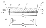
図1.Aは本発明の具体的な一実施例に係るプラズマ発生装置100の構成を示す断面図である。図1.Bは、図1.Aのプラズマ発生装置100の電極2a及び2bの形状の詳細を示す図である。
FIG. A is a cross-sectional view showing a configuration of a
図1.Aのプラズマ発生装置100は、アルミナ(Al2O3)を原料とする焼結体から成る筒状の筐体部10を有し、その両端の開口を、ガス導入口10i及びガス噴出口10oとした。筐体部10内部のガス導入口10i近傍に電極2aを、筐体部10内部のガス噴出口10o近傍に電極2bを配置した。電極2a及び2bは図1.Bに示す通り、互いに対向する面が深さ0.5mm程度の凹部(ホロー)Hを多数有した凹凸面となっている。筐体部10は内径2〜5mm、厚さ0.2〜0.3mm、長さ25cmの管状とし、電極2a及び2bの径は1mm程度に形成する。こうして、商用交流電圧である、60Hz、100Vを用いて約9kVに昇圧し、20mAで電極2a、2b間に印加し、アルゴンをガス導入口10iから導入すると、電極2a及び2bを最大24cmまで離間してもプラズマ(図1.Aで符号Pを付した斜線領域)が発生した。
電極2a及び2b間を長さ24cmとして、筒状の筐体部10の内径を変化させたところ、内径3mm以下で安定して放電した。また、筒状の筐体部10の内径を3mmとして、電極2a及び2b間の長さを変化させたところ、距離24cm以下で安定して放電した。
FIG. The
When the length between the
図1.Aのプラズマ発生装置100において、酸素(O2)を導入しプラズマ化することで、例えば煤を分解可能である。即ち、プラズマ発生装置100をディーゼル排気ガスの浄化に用いうることがわかる。即ち、図1.Aのプラズマ発生装置100において、酸素(O2)及び処理前排気ガス(S)をガス導入口10iから導入し、電極2a、2b間に交流電圧を印加することで、ガス噴出口10oからは酸素(O2)と、二酸化炭素(CO2)及び水(H2O)を含んだ処理済み排気ガス(S’)が得られる。
FIG. In the
図2.Aは本発明の具体的な他の実施例に係るプラズマ発生装置110の構成を示す断面図である。図2.Bは、図2.Aのプラズマ発生装置110のプラズマ化領域Pの長手方向に垂直な断面図(部分図)である。
FIG. A is a cross-sectional view showing a configuration of a
図2.Aのプラズマ発生装置110は、アルミナ(Al2O3)を原料とする焼結体から成る筐体部11を有する。筐体部11は、図2.A内左右方向にスリット状に伸びたガス導入口11i及び複数個の円筒状ガス噴出口11oを有する。ガス導入口11iからプラズマ化領域Pの直上までは、スリット幅(図2.A紙面に対して前後方向、図2Bの左右方向)を1mmとし、内径1〜2mmのガス噴出口11oはプラズマ化領域Pの長手方向に沿って一直線状に形成されている。プラズマ化領域Pは、長手方向に垂直な断面の一辺を2〜5mmの正方形とし、長さを4cmとした。電極2a及び2bは実施例1で用いたものと同じ形状のものを用いた。こうして、商用交流電圧である、60Hz、100Vを用いて約9kVに昇圧し、20mAで電極2a、2b間に印加し、アルゴンをガス導入口11iから導入すると、電極2a及び2b間を4cm迄離間しても、プラズマ化が確認された。
プラズマ発生装置110は、液晶表示器のガラス基板において、異方性導電フィルム(ACF)を貼付する部分を、ACFを貼付する前に洗浄することで、ACFの基板に対する接着度を向上させることができる。
また、電極2a及び2b間を長さ4cmとして、プラズマ化領域Pの断面の一辺の長さを変化させたところ、5mm以下で安定して放電した。また、プラズマ化領域Pの断面の一辺の長さを5mmとして、電極2a及び2b間の長さを変化させたところ、距離4cm以下で安定して放電した。
FIG. A
The
Further, when the length between the
100、110:プラズマ発生装置
10、11:筐体部
10i、11i:ガス導入口
10o、11o:ガス噴出口
2a、2b:各々向き合った表面に凹部(ホロー)を有する一対の電極
P:プラズマ化領域
H:一対の電極2a及び2bの互いに向き合った表面に形成された凹部(ホロー)
DESCRIPTION OF SYMBOLS 100,110:
Claims (8)
長手方向を有する柱状のプラズマ化領域を形成する絶縁体から成る筐体部と、 前記筐体部に内包される前記プラズマ化領域に、長手方向に離間して配設された1対の電極と、
前記プラズマ化領域の長手方向とは垂直な方向からプラズマ発生用ガスを前記プラズマ化領域に導入するプラズマ発生用ガスの導入口と、
前記プラズマ化領域の長手方向とは垂直な方向へ、前記少なくとも一部がプラズマ化したガスを噴出し、前記プラズマ化領域の長手方向に沿って配設された噴出口と
を有することを特徴とする大気圧プラズマ発生装置。 In the atmospheric pressure plasma generator,
A casing made of an insulator that forms a columnar plasma-forming region having a longitudinal direction; and a pair of electrodes disposed in the plasma-forming region contained in the casing so as to be spaced apart in the longitudinal direction; ,
A plasma generating gas inlet for introducing the plasma generating gas into the plasma generating region from a direction perpendicular to the longitudinal direction of the plasma generating region;
And a jet port that ejects the gas that is at least partly plasmatized in a direction perpendicular to the longitudinal direction of the plasmatized region and is disposed along the longitudinal direction of the plasmatized region. An atmospheric pressure plasma generator.
Priority Applications (3)
| Application Number | Priority Date | Filing Date | Title |
|---|---|---|---|
| JP2007255314A JP4296523B2 (en) | 2007-09-28 | 2007-09-28 | Plasma generator |
| PCT/JP2008/066813 WO2009041334A1 (en) | 2007-09-28 | 2008-09-18 | Plasma generator |
| US12/733,896 US8961888B2 (en) | 2007-09-28 | 2008-09-18 | Plasma generator |
Applications Claiming Priority (1)
| Application Number | Priority Date | Filing Date | Title |
|---|---|---|---|
| JP2007255314A JP4296523B2 (en) | 2007-09-28 | 2007-09-28 | Plasma generator |
Related Child Applications (1)
| Application Number | Title | Priority Date | Filing Date |
|---|---|---|---|
| JP2009088989A Division JP5126983B2 (en) | 2009-04-01 | 2009-04-01 | Plasma generator |
Publications (2)
| Publication Number | Publication Date |
|---|---|
| JP2009087697A JP2009087697A (en) | 2009-04-23 |
| JP4296523B2 true JP4296523B2 (en) | 2009-07-15 |
Family
ID=40511220
Family Applications (1)
| Application Number | Title | Priority Date | Filing Date |
|---|---|---|---|
| JP2007255314A Active JP4296523B2 (en) | 2007-09-28 | 2007-09-28 | Plasma generator |
Country Status (3)
| Country | Link |
|---|---|
| US (1) | US8961888B2 (en) |
| JP (1) | JP4296523B2 (en) |
| WO (1) | WO2009041334A1 (en) |
Families Citing this family (6)
| Publication number | Priority date | Publication date | Assignee | Title |
|---|---|---|---|---|
| JP5367738B2 (en) * | 2011-02-03 | 2013-12-11 | シャープ株式会社 | Fixing apparatus and image forming apparatus having the same |
| JP5617817B2 (en) | 2011-10-27 | 2014-11-05 | パナソニック株式会社 | Inductively coupled plasma processing apparatus and inductively coupled plasma processing method |
| JP6099277B2 (en) * | 2012-02-27 | 2017-03-22 | 国立大学法人名古屋大学 | Anti-tumor aqueous solution, anti-cancer agent and method for producing them |
| CN102956432B (en) * | 2012-10-19 | 2015-07-22 | 京东方科技集团股份有限公司 | Atmospheric-pressure plasma processing device of display substrate |
| CN103220874A (en) * | 2012-10-29 | 2013-07-24 | 北京大学 | Plasma array based on dielectric barrier discharging |
| JP6583882B2 (en) * | 2015-08-05 | 2019-10-02 | 国立大学法人名古屋大学 | Fish production method, fry growth promotion method and fish growth promoter |
Family Cites Families (32)
| Publication number | Priority date | Publication date | Assignee | Title |
|---|---|---|---|---|
| JPH0774449B2 (en) * | 1987-10-15 | 1995-08-09 | 住友電気工業株式会社 | Method for producing diamond-coated hydrogen-brittle metal |
| JP2797202B2 (en) | 1989-08-15 | 1998-09-17 | 富士通株式会社 | Method for producing carbon-containing hydrogenated amorphous silicon film |
| JPH0375731A (en) * | 1989-08-18 | 1991-03-29 | Seiko Instr Inc | Phase conjugated wave image generator |
| JP2003027210A (en) | 1994-07-04 | 2003-01-29 | Seiko Epson Corp | Surface treatment method and method for manufacturing display device |
| JP3328498B2 (en) | 1996-02-16 | 2002-09-24 | 株式会社荏原製作所 | Fast atom beam source |
| JPH1036971A (en) * | 1996-07-24 | 1998-02-10 | Nikon Corp | Cvd device |
| US6454860B2 (en) | 1998-10-27 | 2002-09-24 | Applied Materials, Inc. | Deposition reactor having vaporizing, mixing and cleaning capabilities |
| DE19951017A1 (en) * | 1999-10-22 | 2001-05-03 | Bosch Gmbh Robert | Method and device for plasma treatment of surfaces |
| EP1162646A3 (en) * | 2000-06-06 | 2004-10-13 | Matsushita Electric Works, Ltd. | Plasma treatment apparatus and method |
| JP2002368389A (en) * | 2001-06-06 | 2002-12-20 | Matsushita Electric Works Ltd | Method and device for treating printed wiring board |
| US20020187066A1 (en) * | 2001-06-07 | 2002-12-12 | Skion Corporation | Apparatus and method using capillary discharge plasma shower for sterilizing and disinfecting articles |
| EP1430501A2 (en) | 2001-07-02 | 2004-06-23 | Plasmasol Corporation | A novel electrode for use with atmospheric pressure plasma emitter apparatus and method for using the same |
| JP4077704B2 (en) * | 2001-09-27 | 2008-04-23 | 積水化学工業株式会社 | Plasma processing equipment |
| JP2003109799A (en) * | 2001-09-27 | 2003-04-11 | Sakamoto Fujio | Plasma treatment apparatus |
| JP3846303B2 (en) * | 2001-12-19 | 2006-11-15 | 松下電工株式会社 | Surface treatment apparatus and surface treatment method |
| CN1286349C (en) | 2002-02-20 | 2006-11-22 | 松下电工株式会社 | Plasma processing device and plasma processing method |
| KR100490049B1 (en) | 2003-04-14 | 2005-05-17 | 삼성전자주식회사 | Chemical vapor deposition apparatus having a single body type diffuser frame |
| DE112004000057B4 (en) * | 2003-05-27 | 2008-09-25 | Matsushita Electric Works, Ltd., Kadoma | Plasma treatment apparatus and plasma treatment method |
| JP4258296B2 (en) * | 2003-07-09 | 2009-04-30 | トヨタ自動車株式会社 | Plasma reactor |
| KR20060063900A (en) | 2003-07-23 | 2006-06-12 | 세키스이가가쿠 고교가부시키가이샤 | Plasma treating apparatus and its electrode structure |
| JP2005129493A (en) * | 2003-09-30 | 2005-05-19 | Sekisui Chem Co Ltd | Plasma treatment device and its electrode structure |
| EP1565044A1 (en) * | 2004-02-17 | 2005-08-17 | Rasar Holding N.V. | Plasma-generating device and method of treating a gaseous medium |
| JP2006114450A (en) * | 2004-10-18 | 2006-04-27 | Yutaka Electronics Industry Co Ltd | Plasma generating device |
| JP2006196210A (en) * | 2005-01-11 | 2006-07-27 | Univ Nagoya | Plasma generator |
| US20060156983A1 (en) * | 2005-01-19 | 2006-07-20 | Surfx Technologies Llc | Low temperature, atmospheric pressure plasma generation and applications |
| BRPI0608235A2 (en) * | 2005-03-07 | 2009-11-24 | Mounir Laroussi | plasma generator |
| JP2006277953A (en) | 2005-03-25 | 2006-10-12 | Toyohashi Univ Of Technology | Plasma formation device and plasma treatment device as well as plasma formation method and plasma treatment method |
| JP4540519B2 (en) | 2005-03-28 | 2010-09-08 | 富士機械製造株式会社 | Cleaning device, liquid crystal display substrate cleaning device, and liquid crystal display assembly device |
| JP4379376B2 (en) * | 2005-04-19 | 2009-12-09 | パナソニック電工株式会社 | Plasma processing apparatus and plasma processing method |
| JP4684725B2 (en) | 2005-04-20 | 2011-05-18 | 国立大学法人名古屋大学 | Hydrophilic treatment equipment |
| JP2006302652A (en) * | 2005-04-20 | 2006-11-02 | Univ Nagoya | Plasma treatment device |
| JP5396579B2 (en) * | 2005-08-18 | 2014-01-22 | 国立大学法人山梨大学 | Method and apparatus for producing zinc oxide thin film |
-
2007
- 2007-09-28 JP JP2007255314A patent/JP4296523B2/en active Active
-
2008
- 2008-09-18 WO PCT/JP2008/066813 patent/WO2009041334A1/en active Application Filing
- 2008-09-18 US US12/733,896 patent/US8961888B2/en active Active
Also Published As
| Publication number | Publication date |
|---|---|
| US20100296979A1 (en) | 2010-11-25 |
| US8961888B2 (en) | 2015-02-24 |
| JP2009087697A (en) | 2009-04-23 |
| WO2009041334A1 (en) | 2009-04-02 |
Similar Documents
| Publication | Publication Date | Title |
|---|---|---|
| JP5145076B2 (en) | Plasma generator | |
| JP4296523B2 (en) | Plasma generator | |
| JP3959906B2 (en) | Plasma processing apparatus and plasma processing method | |
| JP2004006211A (en) | Plasma treatment device | |
| JP2009503781A (en) | Injection type plasma processing apparatus and method | |
| JP5126983B2 (en) | Plasma generator | |
| JP2008098128A (en) | Atmospheric pressure plasma generating and irradiating device | |
| JP2010009890A (en) | Plasma processing device | |
| KR101254342B1 (en) | Plasma generating device | |
| JP2013004405A (en) | Surface treatment apparatus and surface treatment method | |
| WO2012169588A1 (en) | Gas for plasma generation, plasma generation method, and atmospheric pressure plasma generated thereby | |
| US20100258247A1 (en) | Atmospheric pressure plasma generator | |
| JP2003109799A (en) | Plasma treatment apparatus | |
| JP2003007497A (en) | Atmospheric pressure plasma processing equipment | |
| JP2002177766A (en) | Atmospheric pressure plasma treating device provided with unit for recovering/reusing inert gas | |
| JP5559292B2 (en) | Plasma generator | |
| JP2002008895A (en) | Plasma treatment device and plasma treatment method | |
| KR101273233B1 (en) | Apparatus for plasma treatment | |
| JP2017054943A (en) | Plasma processing device | |
| KR100488361B1 (en) | Atmospheric Pressure Parallel Plate Plasma generator | |
| JP4284861B2 (en) | Surface treatment method and method for manufacturing head for inkjet printer | |
| JP2004211161A (en) | Plasma generating apparatus | |
| JP7144753B2 (en) | Plasma device | |
| JP4501272B2 (en) | Surface treatment method | |
| JP7328500B2 (en) | Atmospheric plasma processing equipment |
Legal Events
| Date | Code | Title | Description |
|---|---|---|---|
| TRDD | Decision of grant or rejection written | ||
| A01 | Written decision to grant a patent or to grant a registration (utility model) |
Free format text: JAPANESE INTERMEDIATE CODE: A01 Effective date: 20090317 |
|
| A01 | Written decision to grant a patent or to grant a registration (utility model) |
Free format text: JAPANESE INTERMEDIATE CODE: A01 |
|
| A61 | First payment of annual fees (during grant procedure) |
Free format text: JAPANESE INTERMEDIATE CODE: A61 Effective date: 20090401 |
|
| R150 | Certificate of patent or registration of utility model |
Ref document number: 4296523 Country of ref document: JP Free format text: JAPANESE INTERMEDIATE CODE: R150 Free format text: JAPANESE INTERMEDIATE CODE: R150 |
|
| FPAY | Renewal fee payment (event date is renewal date of database) |
Free format text: PAYMENT UNTIL: 20120424 Year of fee payment: 3 |
|
| FPAY | Renewal fee payment (event date is renewal date of database) |
Free format text: PAYMENT UNTIL: 20130424 Year of fee payment: 4 |
|
| R250 | Receipt of annual fees |
Free format text: JAPANESE INTERMEDIATE CODE: R250 |
|
| FPAY | Renewal fee payment (event date is renewal date of database) |
Free format text: PAYMENT UNTIL: 20140424 Year of fee payment: 5 |
|
| R250 | Receipt of annual fees |
Free format text: JAPANESE INTERMEDIATE CODE: R250 |
|
| R250 | Receipt of annual fees |
Free format text: JAPANESE INTERMEDIATE CODE: R250 |
|
| R250 | Receipt of annual fees |
Free format text: JAPANESE INTERMEDIATE CODE: R250 |
|
| R250 | Receipt of annual fees |
Free format text: JAPANESE INTERMEDIATE CODE: R250 |
|
| R250 | Receipt of annual fees |
Free format text: JAPANESE INTERMEDIATE CODE: R250 |
|
| R250 | Receipt of annual fees |
Free format text: JAPANESE INTERMEDIATE CODE: R250 |
|
| R250 | Receipt of annual fees |
Free format text: JAPANESE INTERMEDIATE CODE: R250 |
|
| R250 | Receipt of annual fees |
Free format text: JAPANESE INTERMEDIATE CODE: R250 |
|
| R250 | Receipt of annual fees |
Free format text: JAPANESE INTERMEDIATE CODE: R250 |
|
| R250 | Receipt of annual fees |
Free format text: JAPANESE INTERMEDIATE CODE: R250 |
|
| R250 | Receipt of annual fees |
Free format text: JAPANESE INTERMEDIATE CODE: R250 |