JP4291663B2 - Liquid crystal display - Google Patents
Liquid crystal display Download PDFInfo
- Publication number
- JP4291663B2 JP4291663B2 JP2003351350A JP2003351350A JP4291663B2 JP 4291663 B2 JP4291663 B2 JP 4291663B2 JP 2003351350 A JP2003351350 A JP 2003351350A JP 2003351350 A JP2003351350 A JP 2003351350A JP 4291663 B2 JP4291663 B2 JP 4291663B2
- Authority
- JP
- Japan
- Prior art keywords
- signal
- frequency
- liquid crystal
- crystal display
- digital signal
- Prior art date
- Legal status (The legal status is an assumption and is not a legal conclusion. Google has not performed a legal analysis and makes no representation as to the accuracy of the status listed.)
- Expired - Lifetime
Links
- 239000004973 liquid crystal related substance Substances 0.000 title claims description 24
- 238000006243 chemical reaction Methods 0.000 claims description 18
- GJWAPAVRQYYSTK-UHFFFAOYSA-N [(dimethyl-$l^{3}-silanyl)amino]-dimethylsilicon Chemical compound C[Si](C)N[Si](C)C GJWAPAVRQYYSTK-UHFFFAOYSA-N 0.000 description 3
- 238000010586 diagram Methods 0.000 description 3
- 238000000034 method Methods 0.000 description 2
- 238000007796 conventional method Methods 0.000 description 1
- 230000000694 effects Effects 0.000 description 1
- 238000004519 manufacturing process Methods 0.000 description 1
- 230000001360 synchronised effect Effects 0.000 description 1
Images
Classifications
-
- G—PHYSICS
- G02—OPTICS
- G02F—OPTICAL DEVICES OR ARRANGEMENTS FOR THE CONTROL OF LIGHT BY MODIFICATION OF THE OPTICAL PROPERTIES OF THE MEDIA OF THE ELEMENTS INVOLVED THEREIN; NON-LINEAR OPTICS; FREQUENCY-CHANGING OF LIGHT; OPTICAL LOGIC ELEMENTS; OPTICAL ANALOGUE/DIGITAL CONVERTERS
- G02F1/00—Devices or arrangements for the control of the intensity, colour, phase, polarisation or direction of light arriving from an independent light source, e.g. switching, gating or modulating; Non-linear optics
- G02F1/01—Devices or arrangements for the control of the intensity, colour, phase, polarisation or direction of light arriving from an independent light source, e.g. switching, gating or modulating; Non-linear optics for the control of the intensity, phase, polarisation or colour
- G02F1/13—Devices or arrangements for the control of the intensity, colour, phase, polarisation or direction of light arriving from an independent light source, e.g. switching, gating or modulating; Non-linear optics for the control of the intensity, phase, polarisation or colour based on liquid crystals, e.g. single liquid crystal display cells
- G02F1/133—Constructional arrangements; Operation of liquid crystal cells; Circuit arrangements
-
- G—PHYSICS
- G09—EDUCATION; CRYPTOGRAPHY; DISPLAY; ADVERTISING; SEALS
- G09G—ARRANGEMENTS OR CIRCUITS FOR CONTROL OF INDICATING DEVICES USING STATIC MEANS TO PRESENT VARIABLE INFORMATION
- G09G5/00—Control arrangements or circuits for visual indicators common to cathode-ray tube indicators and other visual indicators
- G09G5/003—Details of a display terminal, the details relating to the control arrangement of the display terminal and to the interfaces thereto
- G09G5/005—Adapting incoming signals to the display format of the display terminal
-
- G—PHYSICS
- G09—EDUCATION; CRYPTOGRAPHY; DISPLAY; ADVERTISING; SEALS
- G09G—ARRANGEMENTS OR CIRCUITS FOR CONTROL OF INDICATING DEVICES USING STATIC MEANS TO PRESENT VARIABLE INFORMATION
- G09G3/00—Control arrangements or circuits, of interest only in connection with visual indicators other than cathode-ray tubes
- G09G3/20—Control arrangements or circuits, of interest only in connection with visual indicators other than cathode-ray tubes for presentation of an assembly of a number of characters, e.g. a page, by composing the assembly by combination of individual elements arranged in a matrix no fixed position being assigned to or needed to be assigned to the individual characters or partial characters
- G09G3/34—Control arrangements or circuits, of interest only in connection with visual indicators other than cathode-ray tubes for presentation of an assembly of a number of characters, e.g. a page, by composing the assembly by combination of individual elements arranged in a matrix no fixed position being assigned to or needed to be assigned to the individual characters or partial characters by control of light from an independent source
- G09G3/36—Control arrangements or circuits, of interest only in connection with visual indicators other than cathode-ray tubes for presentation of an assembly of a number of characters, e.g. a page, by composing the assembly by combination of individual elements arranged in a matrix no fixed position being assigned to or needed to be assigned to the individual characters or partial characters by control of light from an independent source using liquid crystals
- G09G3/3611—Control of matrices with row and column drivers
-
- G—PHYSICS
- G09—EDUCATION; CRYPTOGRAPHY; DISPLAY; ADVERTISING; SEALS
- G09G—ARRANGEMENTS OR CIRCUITS FOR CONTROL OF INDICATING DEVICES USING STATIC MEANS TO PRESENT VARIABLE INFORMATION
- G09G5/00—Control arrangements or circuits for visual indicators common to cathode-ray tube indicators and other visual indicators
- G09G5/003—Details of a display terminal, the details relating to the control arrangement of the display terminal and to the interfaces thereto
- G09G5/006—Details of the interface to the display terminal
Landscapes
- Physics & Mathematics (AREA)
- Engineering & Computer Science (AREA)
- General Physics & Mathematics (AREA)
- Computer Hardware Design (AREA)
- Theoretical Computer Science (AREA)
- Nonlinear Science (AREA)
- Chemical & Material Sciences (AREA)
- Crystallography & Structural Chemistry (AREA)
- Mathematical Physics (AREA)
- Optics & Photonics (AREA)
- Control Of Indicators Other Than Cathode Ray Tubes (AREA)
- Liquid Crystal Display Device Control (AREA)
- Liquid Crystal (AREA)
Description
本発明は、チャネル選択機能を有する液晶表示装置に関し、特に、入力信号がディジタル信号である場合、その周波数によってディジタル信号レシーバーから出力される信号のチャネルを自動選択することができる機能を有する液晶表示装置に関する。 The present invention relates to a liquid crystal display device having a channel selection function, and in particular, when an input signal is a digital signal, a liquid crystal display having a function capable of automatically selecting a channel of a signal output from a digital signal receiver according to the frequency. Relates to the device.
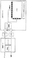
図1は、一般の液晶表示装置の構成を示している。
図1に示すように、液晶表示装置は大別して、外部のデータと電源とを受け取る変換ボードと、変換ボードの出力をLVDSレベルに転換させるLVDS部と、入力部を介してLVDS部からデータと電源を供給されるLCDモジュールとからなる。
ここで、変換ボードは、ディジタル信号受信用のディジタル信号レシーバー(TMDSレシーバー)と解像度の調節のためのスケーラーを含み、LCDモジュールは、LCDパネルに装着される駆動ICを動作させるためのデータ、クロック信号及び各種制御信号を出力するタイミング制御部の以外にLCDパネル、駆動IC、インバータ及びバックライト等からなる。
FIG. 1 shows a configuration of a general liquid crystal display device.
As shown in FIG. 1, the liquid crystal display device is roughly divided into a conversion board that receives external data and power, an LVDS unit that converts the output of the conversion board to an LVDS level, and data from the LVDS unit via the input unit. The LCD module is supplied with power.
Here, the conversion board includes a digital signal receiver (TMDS receiver) for receiving a digital signal and a scaler for adjusting the resolution, and the LCD module includes data and clocks for operating a driving IC mounted on the LCD panel. In addition to the timing control unit that outputs signals and various control signals, it includes an LCD panel, a driving IC, an inverter, a backlight, and the like.
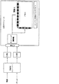
一般に、入力データ信号がディジタル信号(DVI)の場合、ディジタル信号データと共に受け取られるドットクロックは、ディジタル信号レシーバー(TMDSレシーバー)とスケーラーを含む変換ボードで2分周された後、2つのチャネル(even, odd channel : 偶数または奇数駆動ドライバに印加される信号チャネル)を通過した後、LVDS部とLCDモジュールの入力部とを介してタイミング制御部と駆動ICに伝達され、最終的に、パネル上にデータが表示されることになる。ここでLVDS部に印加されるディジタル信号データは、変換ボードに印加される信号周波数と同一であり、2分周されてLVDS部に印加される信号はドット信号である。しかし、変換ボードにスケーラーを含む図1の場合とは異なる図2の場合のように、スケーラーを含まない状態で変換ボードにディジタル信号(DVI)が印加される場合でも、ディジタル信号レシーバーさえあれば、フルスケーリングはできないが、液晶表示装置の中央や一方に片寄るところにディスプレイが可能であった。 In general, when the input data signal is a digital signal (DVI), the dot clock received together with the digital signal data is divided by two by a conversion board including a digital signal receiver (TMDS receiver) and a scaler, and then two channels (even , Odd channel: a signal channel applied to an even or odd drive driver) and then transmitted to the timing control unit and the drive IC via the LVDS unit and the input unit of the LCD module, and finally on the panel Data will be displayed. Here, the digital signal data applied to the LVDS unit is the same as the signal frequency applied to the conversion board, and the signal divided by two and applied to the LVDS unit is a dot signal. However, even when a digital signal (DVI) is applied to the conversion board without the scaler, as in the case of FIG. 2 which is different from the case of FIG. 1 where the conversion board includes the scaler, there is only a digital signal receiver. Although full scaling is not possible, a display is possible in the center of the liquid crystal display device or a part of the liquid crystal display device.
しかし、図2の場合のように、スケーラーを除去して設計した液晶表示装置の場合、入力信号であるディジタル信号に含まれたドット信号がディジタルレシーバーを介して2つのチャネルを介して2分周された後、低電圧差動信号直列インターフェース(LVDS部)を介してタイミング制御部と駆動ICとに印加される時、前記2分周される特定解像度の周波数がタイミング制御部や駆動ICを動作させることに必要な最小周波数より低い場合が存在し、この場合には表示が不可能になる問題がある。 However, in the case of the liquid crystal display device designed by removing the scaler as in the case of FIG. 2, the dot signal included in the digital signal as the input signal is divided by two through the two channels via the digital receiver. After being applied to the timing control unit and the driving IC via the low voltage differential signal serial interface (LVDS unit), the frequency of the specific resolution divided by 2 operates the timing control unit and the driving IC. There is a case where the frequency is lower than the minimum frequency required for the display, and in this case, there is a problem that display is impossible.
表示が不可能な信号が入力された場合に、入力信号とは非同期のクロック及び同期信号に切換える方法が提案されている(例えば、特許文献1参照)。しかし、この方法は複雑な回路が必要であるという問題点がある。
本発明は、前述の問題を解決するために提案されたもので、入力信号がディジタル信号の場合、解像度の調節のためのスケーラーが不要で、その代わりにディジタル信号レシーバーでチャネルを選択する機能を備えて、2つのチャネルを介して2分周されるドット信号の周波数がタイミング制御部や駆動ICが動作することができる最小限の周波数より低い場合は、1つのチャネルのみを使用してタイミング制御部や駆動ICが動作することができる最小限の周波数より大きくし、タイミング制御部や駆動ICが動作することができる最小限の周波数より高い場合には、従来の方法の通り、2つのチャネルを使用することにより、入力信号によりチャネルを選択することができる機能を備えるようにして、スケーラーのない場合にも安定されたディスプレイが可能にした液晶表示装置を提供することを目的とする。 The present invention has been proposed to solve the above-described problems. When the input signal is a digital signal, a scaler for adjusting the resolution is unnecessary, and instead, a function of selecting a channel with a digital signal receiver is provided. If the frequency of the dot signal divided by two through two channels is lower than the minimum frequency at which the timing control unit and the driving IC can operate, timing control is performed using only one channel. If the frequency is higher than the minimum frequency at which the timing control unit or the driving IC can operate and is higher than the minimum frequency at which the timing control unit or the driving IC can operate, the two channels are set as in the conventional method. By using it, it is possible to select the channel according to the input signal, and it is stable even without a scaler. And to provide a liquid crystal display device which display is possible.
本発明に係る実施の形態であって、外部電源とドット信号を含むディジタルデータ信号を基本的に受信する変換ボードを備える液晶表示装置の変換ボードは、前記外部電源及び前記ドット信号とを含むディジタル信号を受信するディジタル信号レシーバーと、前記ディジタル信号レシーバーから2分周され、出力される前記ドット信号の周波数が前記液晶表示装置の駆動装置で使用される周波数より高いかどうかを比較する比較機を備える。
本発明において、2分周されるドット信号の周波数が前記駆動装置で使用される周波数より高い場合には、ディジタル信号レシーバーの2チャネルを使用して前記液晶表示装置のモジュールに前記ディジタル信号を印加し、2分周されるドット信号の周波数が前記駆動装置で使用される周波数より低い場合には、ディジタル信号レシーバーの1チャネルを使用して前記液晶表示装置のモジュールに前記ディジタル信号を印加する。
本発明において、ドット信号の周波数を判断するために、前記比較機には前記ディジタルデータ信号中で垂直周波数信号または水平周波数信号を印加する。
An embodiment of the present invention is a conversion board of a liquid crystal display device comprising a conversion board that basically receives an external power supply and a digital data signal including a dot signal. The conversion board includes the external power supply and the dot signal. A digital signal receiver for receiving a signal, and a comparator for comparing whether the frequency of the dot signal that is divided by two from the digital signal receiver and output is higher than the frequency used in the driving device of the liquid crystal display device Prepare.
In the present invention, when the frequency of the dot signal divided by two is higher than the frequency used in the driving device, the digital signal is applied to the module of the liquid crystal display device using two channels of the digital signal receiver. When the frequency of the dot signal divided by two is lower than the frequency used in the driving device, the digital signal is applied to the module of the liquid crystal display device using one channel of the digital signal receiver .
In the present invention, in order to determine the frequency of the dot signal, a vertical frequency signal or a horizontal frequency signal is applied to the comparator in the digital data signal.
本発明に係る液晶表示装置は、変換ボードの中で高コストで、しかも大面積を占めていたスケーラーを使用しないので、製造コストを低減する効果がある。 The liquid crystal display device according to the present invention has an effect of reducing the manufacturing cost because it does not use a scaler that occupies a large area in the conversion board.
以下、添付の図面を参照しながら本発明の実施の形態について、より詳細に説明する。
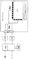
図3は、本発明に係る変換ボードを備える液晶表示装置の実施の形態である。図3に示すように、本発明に係る液晶表示装置の変換ボードは、ディジタル信号受信用のディジタル信号レシーバー(TMDSレシーバー)と比較機とを備えており、以下のように動作する。
Hereinafter, embodiments of the present invention will be described in more detail with reference to the accompanying drawings.
FIG. 3 shows an embodiment of a liquid crystal display device including the conversion board according to the present invention. As shown in FIG. 3, the conversion board of the liquid crystal display device according to the present invention includes a digital signal receiver (TMDS receiver) for receiving digital signals and a comparator, and operates as follows.
ディジタルデータ信号がディジタル信号レシーバーに印加されるとディジタル信号レシーバーの出力信号において、ドット信号の周波数情報を含む水平周波数信号(Hsync)が比較機に印加される(或は、ドット信号の周波数情報を含む垂直周波数信号(Vsync)を使用することもできる)。水平周波数信号を受信した比較機はディジタル信号レシーバーの2つのチャネルにより2分周される周波数を計算し、この周波数の値がタイミング制御部や駆動ICが動作することができる最小限の周波数より高いがどうかを比較する。 When the digital data signal is applied to the digital signal receiver, a horizontal frequency signal (Hsync) including the frequency information of the dot signal is applied to the comparator in the output signal of the digital signal receiver (or the frequency information of the dot signal is A vertical frequency signal (Vsync) can also be used). The comparator that has received the horizontal frequency signal calculates the frequency divided by two by the two channels of the digital signal receiver, and the value of this frequency is higher than the minimum frequency at which the timing control unit and the driving IC can operate. Compare whether or not.
比較の結果、2つのチャネルにより2分周される周波数が低電圧差動信号直列インターフェース(LVDS)が動作することができる最小限の周波数より高い場合、比較機はディジタル信号レシーバーに、例えば、ハイレベルの信号を転送する。ハイレベルの信号を受信したディジタル信号レシーバーは、2つのチャネルを使用するようにセットされて、入力ディジタル信号に含まれたドット信号を2分周し、2つの低電圧差動信号直列インターフェース(LVDS)に転送する。2つの低電圧差動信号直列インターフェース(LVDS)を経た信号はタイミング制御部と駆動ICとに転送され、正常なディスプレイ動作が可能にする。 As a result of the comparison, if the frequency divided by two by the two channels is higher than the minimum frequency at which the low voltage differential signal serial interface (LVDS) can operate, the comparator will connect to the digital signal receiver, eg, high Transfer level signal. The digital signal receiver that receives the high level signal is set to use two channels, divides the dot signal included in the input digital signal by 2, and divides the two low voltage differential signal serial interfaces (LVDS). ). The signal that has passed through the two low voltage differential signal serial interfaces (LVDS) is transferred to the timing controller and the driving IC, thereby enabling normal display operation.
一方、2つのチャネルにより2分周される周波数が低電圧差動信号直列インターフェース(LVDS)が動作することができる最小限の周波数より低い場合、比較機はディジタル信号レシーバーにロウレベルの信号を転送する。ロウレベルの信号を受信したディジタル信号レシーバーは1つのチャネルを使用するようにセットされる。この場合は、入力ディジタル信号に含まれたドット信号は分周されることなく、また、ディジタル信号は1つの低電圧差動信号直列インターフェース(LVDS)のみに転送される。2分周されていないドット周波数はタイミング制御部と駆動ICが動作することができる最小限の周波数より低いので、タイミング制御部と駆動ICとは正常に動作する。 On the other hand, if the frequency divided by two by the two channels is lower than the minimum frequency at which the low voltage differential signal serial interface (LVDS) can operate, the comparator transfers a low level signal to the digital signal receiver. . The digital signal receiver that has received the low level signal is set to use one channel. In this case, the dot signal included in the input digital signal is not divided, and the digital signal is transferred to only one low voltage differential signal serial interface (LVDS). Since the dot frequency that is not divided by two is lower than the minimum frequency at which the timing control unit and the driving IC can operate, the timing control unit and the driving IC operate normally.
Claims (2)
前記外部電源及び前記ドット信号と、を含むディジタル信号を受信するディジタル信号レシーバーと、
前記ディジタル信号レシーバーから2分周され、出力される前記ドット信号の周波数が前記液晶表示装置のタイミング制御部及び駆動ICを動作させることに必要な最小周波数より高いかどうかを比較する比較機を備え、
前記2分周されたドット信号の周波数が前記タイミング制御部及び駆動ICを動作させることに必要な最小周波数より高い場合には、前記ディジタル信号レシーバーの2チャネルを使用して前記液晶表示装置のモジュールに前記ディジタル信号を印加し、前記2分周されたドット信号の周波数が前記タイミング制御部及び駆動ICを動作させることに必要な最小周波数より低い場合には、前記ディジタル信号レシーバーの1チャネルを使用して前記液晶表示装置のモジュールに前記ディジタル信号を印加することを特徴とする液晶表示装置。 In a liquid crystal display device including a conversion board for receiving a digital data signal including an external power source and a dot signal, the conversion board includes:
A digital signal receiver for receiving a digital signal including the external power source and the dot signal;
A comparator for comparing whether the frequency of the dot signal that is divided by two from the digital signal receiver and output is higher than the minimum frequency required to operate the timing control unit and the driving IC of the liquid crystal display device; ,
When the frequency of the frequency-divided dot signal is higher than the minimum frequency required for operating the timing control unit and the driving IC, the module of the liquid crystal display device using two channels of the digital signal receiver If the frequency of the dot signal divided by two is lower than the minimum frequency required to operate the timing control unit and the driving IC, one channel of the digital signal receiver is used. The digital signal is applied to the module of the liquid crystal display device.
Applications Claiming Priority (1)
| Application Number | Priority Date | Filing Date | Title |
|---|---|---|---|
| KR10-2003-0019949A KR100494713B1 (en) | 2003-03-31 | 2003-03-31 | Liquid crystal display |
Publications (2)
| Publication Number | Publication Date |
|---|---|
| JP2004302415A JP2004302415A (en) | 2004-10-28 |
| JP4291663B2 true JP4291663B2 (en) | 2009-07-08 |
Family
ID=32985909
Family Applications (1)
| Application Number | Title | Priority Date | Filing Date |
|---|---|---|---|
| JP2003351350A Expired - Lifetime JP4291663B2 (en) | 2003-03-31 | 2003-10-09 | Liquid crystal display |
Country Status (5)
| Country | Link |
|---|---|
| US (1) | US7209134B2 (en) |
| JP (1) | JP4291663B2 (en) |
| KR (1) | KR100494713B1 (en) |
| CN (1) | CN100370505C (en) |
| TW (1) | TWI249725B (en) |
Families Citing this family (9)
| Publication number | Priority date | Publication date | Assignee | Title |
|---|---|---|---|---|
| JP2004341101A (en) * | 2003-05-14 | 2004-12-02 | Nec Corp | Display panel drive unit |
| JP2005234241A (en) * | 2004-02-19 | 2005-09-02 | Sharp Corp | Liquid crystal display |
| US20070182342A1 (en) * | 2005-08-02 | 2007-08-09 | Texas Instruments Incorporated | Lcd backlight driver |
| TWI284872B (en) * | 2005-11-22 | 2007-08-01 | Chi Mei Optoelectronics Corp | Flat panel display having a data transfer interface with multi-channels and image transfer method thereof |
| JP4171927B2 (en) * | 2006-09-19 | 2008-10-29 | 船井電機株式会社 | LCD panels, plasma display panels, and wide-screen LCD televisions |
| KR101386457B1 (en) * | 2007-05-22 | 2014-04-18 | 삼성디스플레이 주식회사 | Liquid crystal display and driving method of the same |
| TWI380269B (en) * | 2007-10-05 | 2012-12-21 | Au Optronics Corp | Display and method of transmitting image data therein |
| CN106515771B (en) * | 2016-12-14 | 2018-08-03 | 中车株洲电力机车有限公司 | A kind of compressor control method of rail vehicle fixed frequency air conditioner |
| CN117456949A (en) * | 2023-10-13 | 2024-01-26 | Tcl华星光电技术有限公司 | Display device, equipment and driving method |
Family Cites Families (7)
| Publication number | Priority date | Publication date | Assignee | Title |
|---|---|---|---|---|
| JP3756203B2 (en) * | 1993-09-22 | 2006-03-15 | セイコーエプソン株式会社 | Memory circuit and flat panel drive circuit |
| JPH0944122A (en) * | 1995-08-03 | 1997-02-14 | Sharp Corp | LCD display system |
| KR100596586B1 (en) * | 1999-07-20 | 2006-07-04 | 삼성전자주식회사 | Screen state automatic adjustment device of liquid crystal display device and its method |
| KR100327369B1 (en) * | 1999-07-31 | 2002-03-06 | 구자홍 | Apparatus and method for interfacing video information of computer system |
| US6313813B1 (en) * | 1999-10-21 | 2001-11-06 | Sony Corporation | Single horizontal scan range CRT monitor |
| JP3838844B2 (en) * | 2000-02-14 | 2006-10-25 | Necビューテクノロジー株式会社 | Reference signal generating apparatus and signal generating method thereof |
| TW493159B (en) * | 2001-01-05 | 2002-07-01 | Acer Peripherals Inc | Method and device to detect the full-screen size by data enable signal |
-
2003
- 2003-03-31 KR KR10-2003-0019949A patent/KR100494713B1/en not_active Expired - Lifetime
- 2003-09-23 TW TW092126148A patent/TWI249725B/en not_active IP Right Cessation
- 2003-09-24 US US10/669,995 patent/US7209134B2/en not_active Expired - Lifetime
- 2003-10-09 JP JP2003351350A patent/JP4291663B2/en not_active Expired - Lifetime
- 2003-11-03 CN CNB2003101141140A patent/CN100370505C/en not_active Expired - Lifetime
Also Published As
| Publication number | Publication date |
|---|---|
| CN100370505C (en) | 2008-02-20 |
| TWI249725B (en) | 2006-02-21 |
| CN1534584A (en) | 2004-10-06 |
| KR20040085306A (en) | 2004-10-08 |
| US7209134B2 (en) | 2007-04-24 |
| TW200419516A (en) | 2004-10-01 |
| US20040189628A1 (en) | 2004-09-30 |
| KR100494713B1 (en) | 2005-06-13 |
| JP2004302415A (en) | 2004-10-28 |
Similar Documents
| Publication | Publication Date | Title |
|---|---|---|
| US7116322B2 (en) | Display apparatus and controlling method thereof | |
| JP4481460B2 (en) | Liquid crystal display device and driving method thereof | |
| US20090213033A1 (en) | Timing controller for reducing power consumption and display device having the same | |
| US20090201274A1 (en) | Timing Signal Generating Circuit, Electronic Apparatus, Display Apparatus, Image-Reception Apparatus, and Driving Method | |
| JP2007011334A (en) | Timing controller for display device, display device including the same, and method for controlling the same | |
| JP4291663B2 (en) | Liquid crystal display | |
| KR20040074305A (en) | Driver circuit of liquid crystal pannel and liquid crystal display device using this | |
| US7893951B2 (en) | Image display apparatus and image display method | |
| EP1755106A1 (en) | Display apparatus and control method thereof | |
| JP2003195828A (en) | Display device, information processor, display method, program, and recording medium | |
| KR100429880B1 (en) | Circuit and method for controlling LCD frame ratio and LCD system having the same | |
| US20080068323A1 (en) | Integrated display panel | |
| JP2006018149A (en) | Liquid crystal display device | |
| JP2003058117A (en) | Display device, electronic device, and display control method | |
| KR101187572B1 (en) | Drive control circuit of liquid display device | |
| KR100425091B1 (en) | Apparatus for transmitting control data in display device | |
| KR100845865B1 (en) | Monitor and Resolution Control Method Using the Same | |
| EP4439543A1 (en) | A display processing device, a data transmission method, and an image data inspection method | |
| KR100521262B1 (en) | Driving Method of Liquid Crystal Display Using Graphic Card | |
| JP2011112721A (en) | Timing controller and display device using the same | |
| KR100402903B1 (en) | display apparatus | |
| KR19990080023A (en) | Display device for automatically adjusting image position according to display mode change and computer system using same | |
| KR20080008483A (en) | Liquid crystal display and driving method thereof | |
| JP2003131643A (en) | Image display device | |
| JP2007264572A (en) | Liquid crystal display device |
Legal Events
| Date | Code | Title | Description |
|---|---|---|---|
| A621 | Written request for application examination |
Free format text: JAPANESE INTERMEDIATE CODE: A621 Effective date: 20050712 |
|
| A131 | Notification of reasons for refusal |
Free format text: JAPANESE INTERMEDIATE CODE: A131 Effective date: 20081118 |
|
| A521 | Request for written amendment filed |
Free format text: JAPANESE INTERMEDIATE CODE: A523 Effective date: 20090217 |
|
| TRDD | Decision of grant or rejection written | ||
| A01 | Written decision to grant a patent or to grant a registration (utility model) |
Free format text: JAPANESE INTERMEDIATE CODE: A01 Effective date: 20090331 |
|
| A01 | Written decision to grant a patent or to grant a registration (utility model) |
Free format text: JAPANESE INTERMEDIATE CODE: A01 |
|
| A61 | First payment of annual fees (during grant procedure) |
Free format text: JAPANESE INTERMEDIATE CODE: A61 Effective date: 20090403 |
|
| R150 | Certificate of patent or registration of utility model |
Free format text: JAPANESE INTERMEDIATE CODE: R150 Ref document number: 4291663 Country of ref document: JP Free format text: JAPANESE INTERMEDIATE CODE: R150 |
|
| FPAY | Renewal fee payment (event date is renewal date of database) |
Free format text: PAYMENT UNTIL: 20120410 Year of fee payment: 3 |
|
| FPAY | Renewal fee payment (event date is renewal date of database) |
Free format text: PAYMENT UNTIL: 20120410 Year of fee payment: 3 |
|
| FPAY | Renewal fee payment (event date is renewal date of database) |
Free format text: PAYMENT UNTIL: 20130410 Year of fee payment: 4 |
|
| R250 | Receipt of annual fees |
Free format text: JAPANESE INTERMEDIATE CODE: R250 |
|
| FPAY | Renewal fee payment (event date is renewal date of database) |
Free format text: PAYMENT UNTIL: 20140410 Year of fee payment: 5 |
|
| R250 | Receipt of annual fees |
Free format text: JAPANESE INTERMEDIATE CODE: R250 |
|
| R250 | Receipt of annual fees |
Free format text: JAPANESE INTERMEDIATE CODE: R250 |
|
| R250 | Receipt of annual fees |
Free format text: JAPANESE INTERMEDIATE CODE: R250 |
|
| R250 | Receipt of annual fees |
Free format text: JAPANESE INTERMEDIATE CODE: R250 |
|
| R250 | Receipt of annual fees |
Free format text: JAPANESE INTERMEDIATE CODE: R250 |
|
| R250 | Receipt of annual fees |
Free format text: JAPANESE INTERMEDIATE CODE: R250 |
|
| R250 | Receipt of annual fees |
Free format text: JAPANESE INTERMEDIATE CODE: R250 |
|
| R250 | Receipt of annual fees |
Free format text: JAPANESE INTERMEDIATE CODE: R250 |
|
| R250 | Receipt of annual fees |
Free format text: JAPANESE INTERMEDIATE CODE: R250 |
|
| R250 | Receipt of annual fees |
Free format text: JAPANESE INTERMEDIATE CODE: R250 |
|
| R250 | Receipt of annual fees |
Free format text: JAPANESE INTERMEDIATE CODE: R250 |
|
| EXPY | Cancellation because of completion of term |