JP4285951B2 - Zoom lens and electronic imaging apparatus using the same - Google Patents
Zoom lens and electronic imaging apparatus using the same Download PDFInfo
- Publication number
- JP4285951B2 JP4285951B2 JP2002225619A JP2002225619A JP4285951B2 JP 4285951 B2 JP4285951 B2 JP 4285951B2 JP 2002225619 A JP2002225619 A JP 2002225619A JP 2002225619 A JP2002225619 A JP 2002225619A JP 4285951 B2 JP4285951 B2 JP 4285951B2
- Authority
- JP
- Japan
- Prior art keywords
- lens
- lens group
- group
- refractive power
- zoom
- Prior art date
- Legal status (The legal status is an assumption and is not a legal conclusion. Google has not performed a legal analysis and makes no representation as to the accuracy of the status listed.)
- Expired - Fee Related
Links
Images


Classifications
-
- G—PHYSICS
- G02—OPTICS
- G02B—OPTICAL ELEMENTS, SYSTEMS OR APPARATUS
- G02B13/00—Optical objectives specially designed for the purposes specified below
- G02B13/22—Telecentric objectives or lens systems
-
- G—PHYSICS
- G02—OPTICS
- G02B—OPTICAL ELEMENTS, SYSTEMS OR APPARATUS
- G02B15/00—Optical objectives with means for varying the magnification
- G02B15/14—Optical objectives with means for varying the magnification by axial movement of one or more lenses or groups of lenses relative to the image plane for continuously varying the equivalent focal length of the objective
- G02B15/144—Optical objectives with means for varying the magnification by axial movement of one or more lenses or groups of lenses relative to the image plane for continuously varying the equivalent focal length of the objective having four groups only
- G02B15/1445—Optical objectives with means for varying the magnification by axial movement of one or more lenses or groups of lenses relative to the image plane for continuously varying the equivalent focal length of the objective having four groups only the first group being negative
- G02B15/144511—Optical objectives with means for varying the magnification by axial movement of one or more lenses or groups of lenses relative to the image plane for continuously varying the equivalent focal length of the objective having four groups only the first group being negative arranged -+-+
-
- G—PHYSICS
- G02—OPTICS
- G02B—OPTICAL ELEMENTS, SYSTEMS OR APPARATUS
- G02B5/00—Optical elements other than lenses
- G02B5/04—Prisms
Landscapes
- Physics & Mathematics (AREA)
- General Physics & Mathematics (AREA)
- Optics & Photonics (AREA)
- Lenses (AREA)
- Structure And Mechanism Of Cameras (AREA)
Description
【0001】
【発明の属する技術分野】
本発明は、ズームレンズ及びそれを用いた電子撮像装置に関し、特に、ズームレンズ等の光学系部分の工夫により奥行き方向の薄型化を実現した、ビデオカメラやデジタルカメラを始めとする電子撮像装置に関するものである。
【0002】
【従来の技術】
近年、銀塩35mmフィルム(135フォーマット)カメラに代わる次世代カメラとしてデジタルカメラ(電子カメラ)が注目されてきている。さらに、それは業務用高機能タイプからポータブルな普及タイプまで幅広い範囲でいくつものカテゴリーを有するようになってきている。
【0003】
本発明においては、特にポータブルな普及タイプのカテゴリーに注目し、高画質を確保しながら奥行きが薄く使い勝手の良好なビデオカメラ、デジタルカメラを実現する技術を提供することをねらっている。カメラの奥行き方向を薄くするのに最大のネックとなっているのは、光学系、特にズームレンズ系の最も物体側の面から撮像面までの厚みである。
【0004】
最近におけるカメラボディ薄型化技術の主流は、撮影時には光学系がカメラボディ内から突出しているが、携帯時には収納するいわゆる沈胴式鏡筒を採用することである。沈胴式鏡筒を採用して効果的に薄型化できる可能性を有する光学系の例としては、特開平11−194274、特開平11−287953、特開2000−9997等のものがある。これらは、物体側から順に、負の屈折力を有する第1群、正の屈折力を含む第2群を有しており、共に変倍時には移動する。しかし、沈胴式鏡筒を採用するとレンズ収納状態から使用状態に立ち上げるための時間が掛かり使い勝手上好ましくない。また、最も物体側のレンズ群を可動とすると、防水・防塵上好ましくない。
【0005】
【発明が解決しようとする課題】
本発明は従来技術のこのような問題点に鑑みてなされたものであり、その目的は、沈胴式鏡筒に見られるようなカメラの使用状態への立ち上げ時間(レンズのせり出し時間)がなく、防水・防塵上も好ましく、また、奥行き方向が極めて薄いカメラとするために、光学系の光路(光軸)をミラー等の反射光学素子で折り曲げる構成がとりやすく、高ズーム比、広画角、小さいF値、少ない収差等、高い光学仕様性能を有するズームレンズを提供することである。
【0006】
【課題を解決するための手段】
上記目的を達成するために本発明のズームレンズは、物体側から順に、負レンズと光路を折り曲げるための反射光学素子を含んでおり変倍時に固定であるレンズ群A、広角端から望遠端に変倍する際に一方向にのみ移動するレンズ群B、変倍時に位置が不動の開口絞りを有し、以下の条件を満足することを特徴とするものである。
【0007】
(1) 0.45<log γB /log γ<0.85
ただし、γ、γB はそれぞれ、
γ=fT /fW
γB =望遠端におけるレンズ群Bの倍率/広角端におけるレンズ群Bの倍率とし、fW 、fT はそれぞれズームレンズ全系の広角端、望遠端の焦点距離とする。
【0008】
以下に、本発明において上記構成をとる理由と作用について説明する。
【0009】
前記目的を達成するために、本発明においては、負レンズと光路を折り曲げるための反射光学素子を含んでおり変倍時に固定であるレンズ群A、広角端から望遠端に変倍する際に一方向にのみ移動するレンズ群B、変倍時に位置が不動の開口絞りを有しを有するズームレンズを採用している。
【0010】
このように、光路を折り曲げるための反射光学素子を最も物体側のレンズ群Aに設け、さらには、機構的な煩雑さを避けるために折り曲げ機能を有するレンズ群Aを変倍時固定とすることにより、カメラの奥行き方向を薄くすることができる。また、奥行き方向が極めて薄いカメラとするためには、レンズ鏡筒が光路折り曲げ個所よりも像側のレンズ径方向へ肥大化することも回避するように考慮しなくてはならない。例えば、絞り機構(シャッター機構を含む場合もある)を変倍と同時に移動させると、光量調節制御機構も一緒に移動させることになり、その移動スペースの確保のために鏡筒が径方向に肥大化してしまう。
【0011】
したがって、本発明においては、絞り機構位置を変倍時不動としている。
【0012】
しかしながら、変倍時に一方向に移動し変倍に大きく寄与するレンズ群よりも物体側に開口絞りを固定すると、広角端から望遠端に至るまでのF値の変化量が著しく大きく不具合である。したがって、少なくとも位置不動の開口絞りよりも物体側に変倍に寄与するレンズ群、つまり、広角端から望遠端に変倍する際に一方向にのみ移動するレンズ群Bを配置する必要がある。一方、レンズ群Bの移動量が大きいと入射瞳が深くなって光路屈曲が成り立たなくなったり、射出側のテレセントリック性を満足できなくなるため、広角端から望遠端にかけてのレンズ群Bの倍率変化の度合いを条件(1)の範囲に抑制するしかない。
【0013】
(1) 0.45<log γB /log γ<0.85
ただし、γ、γB はそれぞれ、
γ=fT /fW
γB =望遠端におけるレンズ群Bの倍率/広角端におけるレンズ群Bの倍率とし、fW 、fT はそれぞれズームレンズ全系の広角端、望遠端の焦点距離とする。
【0014】
この条件(1)の上限の0.85を越えると、入射瞳が深くなって光路屈曲の成立性や、射出側のテレセントリック性に支障をきたしやすい。下限の0.45を越えると、変倍比が稼げないか、あるいは、開口絞りより後ろのレンズ群で変倍比を補った場合、その補強量が大きい程広角端から望遠端に至るまでのF値の変化量が大きくなる。なお、ある程度の補強であればF値の変化量が小さいので、開口絞りよりも像側に、広角端から望遠端に変倍する際、一方向にのみ移動するレンズ群(変倍に寄与するレンズ群)を有するとよい。
【0015】
なお、以下のようにするとよりよい。
【0016】
(1)’ 0.5<log γB /log γ<0.8
さらに、以下のようにすると最もよい。
【0017】
(1)” 0.55<log γB /log γ<0.77
因みに、レンズ群Aが負の屈折力を有する場合には、レンズ群Bが正の屈折力となり、レンズ群Aが正の屈折力を有する場合には、レンズ群Bが負の屈折力となる。後者の場合、開口絞りから像側は、光路の順に、正の屈折力であるレンズ群C、正の屈折力であるレンズ群Dを有し、広角端から望遠端に変倍する際には、レンズ群Dが像側にのみ移動することで変倍比を補強する。前者の場合については、後述する。さらに、開口絞りよりも物体側にあるレンズ群Bと像側にあるレンズ群Cとは屈折力が異符号である。
【0018】
また、光路屈曲によるスペース確保の代償として、入射瞳が深くなったり変倍比の確保が困難になることがあるが、できれば光路を折り曲げるための反射光学素子を以下の媒質条件を満たすプリズムブロックとするのがよい。
【0019】
(2) 1.55<npri <1.97
ただし、npri はレンズ群Aの光路を折り曲げるための反射光学素子がプリズムの場合におけるd線に対する媒質の屈折率である。
【0020】
条件式(2)の下限値の1.55を越えると、プリズムを含めた物体側の光学素子が大型化しやすく収差補正上も不利であるし、レンズ群B以降の群の合成倍率が低くなり、レンズ群Bの移動量が増大するか高いズーム比を確保することが困難となる。上限値の1.97を越えると、プリズムのコストが高くなる。
【0021】
なお、以下のようにするとよりよい。
【0022】
(2)’ 1.65<npri <1.95
さらに、以下のようにすると最もよい。
【0023】
(2)” 1.75<npri <1.93
また、レンズ群Aは、物体側に凸面を有する負メニスカスレンズを有する副群A1と、光路を折り曲げるための反射光学素子と、少なくとも正レンズを含む副群A2とから構成するのが望ましい。
【0024】
そして、その副群A2は、色収差や歪曲収差等の軸外収差を補正するために、物体側から順に、負レンズ・正レンズの2枚にて構成し、以下の条件を満足するとよい。
【0025】
レンズ群Aのプリズムブロックの光線入射面から光線射出面まで光軸に沿って測ったときの空気換算長dで規定する場合は、以下のようにするのがよい。
【0026】
(3) 0.5<d/L<1.2
ただし、Lは撮像素子の有効撮像領域(略矩形)の対角長である。
【0027】
この条件(3)の上限値の1.2を越えると、プリズムを含めた物体側の光学素子が大型化しやすく収差補正上も不利であるし、レンズ群B以降の群の合成倍率が低くなりレンズ群Bの移動量が増大するか、高いズーム比を確保することが困難となる。下限値の0.5を越えると、画像周辺部の結像に寄与する光束が満足に像面に達しないし、あるいはゴーストが発生しやすい。なお、この条件を満足できるならば、反射前後の媒質が空気の表面鏡でも構わない。
【0028】
また、光路を折り曲げる方向が有効画面の長辺方向の場合、短辺方向の場合、それぞれ以下の範囲がよい。
【0029】
(3−1) 0.75<d/L<1.1
(3−2) 0.55<d/L<0.9
さらに、それぞれ以下のようにすると最もよい。
【0030】
(3−1)’0.8<d/L<1.0
(3−2)’0.6<d/L<0.8
なお、光路を折り曲げるための反射光学素子は、屈折率の高い媒質のプリズムにて構成するのが、プリズムを含めた物体側の光学素子の小型化や収差補正上有利である。
【0031】
本発明のズームレンズは、最も物体側のレンズ群が変倍時固定であり、さらに絞り位置も固定できることが特徴であるが、中でも最も物体側のレンズ群は負の屈折力を有し、条件(1)を満足することが最重要な特徴である。
【0032】
光路に従って最も物体側のレンズ群Aが負の屈折力を有する場合には、レンズ群Bが正の屈折力となるが、その場合も条件(1)を満足することが望ましい。さらに、各レンズ群の移動量をできるだけ小さくして光学全長を短くするために、以下の条件(4)のように、レンズ群B以降の合成系の倍率が−1倍近傍にて変倍するのがよい。ただし、収差補正上は倍率の絶対値は低い方が有利である。したがって、望遠端においては以下の条件を満足するのがよい。
【0033】
(4) 0.75<−βRt<1.5
ただし、βRtはレンズ群B以降の望遠端における合成倍率(無限遠物点)である。
【0034】
条件(4)の上限の1.5、下限の0.75何れを越えても、各レンズ群の相対的間隔の変化量が大きくなり、光学全長が長くなりがちである。
【0035】
なお、以下のようにするとよりよい。
【0036】
(4)’ 0.8<−βRt<1.3
さらに、以下のようにすると最もよい。
【0037】
(4)” 0.85<−βRt<1.15
加えて、開口絞りから像側には、光路の順に、負の屈折力であるレンズ群C、正の屈折力であるレンズ群Dを有し、広角端から望遠端に変倍する際に少なくとも一方のレンズ群が像側にのみ移動することで、変倍比を補強するようにすることが望ましい。
【0038】
さらに、開口絞りよりも物体側にあるレンズ群Bと像側にあるレンズ群Cとは屈折力が異符号であるため、変倍時には互いに反対方向に移動するが、無限遠合焦時に広角端から望遠端に変倍する際のレンズ群B・レンズ群Cのそれぞれの移動量M2 、M3 の比を以下の条件(5)のようにするとよい。
【0039】
(5) −1.0<M3 /M2 <−0.3
この条件(5)の上限の−0.3を越えると、入射瞳が深くなって光路屈曲の成立性や、射出側のテレセントリック性に支障を来しやすい。下限の−1.0を越えると、広角端から望遠端に至るまでのF値の変化量が大きくなる。
【0040】
なお、以下のようにするとよりよい。
【0041】
(5)’ −0.9<M3 /M2 <−0.4
さらに、以下のようにすると最もよい。
【0042】
(5)” −0.85<M3 /M2 <−0.5
また、合焦については開口絞りより像側の何れかのレンズ群にて行なうのがよい。
【0043】
また、無限遠合焦時に広角端から望遠端に変倍する際の、レンズ群C・レンズ群Dのそれぞれの移動量M3 、M4 の比を以下の条件(6)のようにするとよい。
【0044】
(6) 0.3<M4 /M3 <0.9
この条件(6)の上限の0.9を越えると、変倍比を稼ぐことが困難となる。下限の0.3を越えると、フォーカスを実施するための移動スペースの確保が困難となる。
【0045】
なお、以下のようにするとよりよい。
【0046】
(6)’ 0.4<M4 /M3 <0.8
さらに、以下のようにすると最もよい。
【0047】
(6)” 0.5<M4 /M3 <0.7
ところで、レンズ群Aは、前記したように、物体側に凸面を有する負メニスカスレンズを有する副群A1、光路を折り曲げるための反射光学素子、少なくとも正レンズを含む副群A2から構成するとよい。特に、副群A1は1枚のみで構成し、副群A2で色収差等の各収差補正を行なうのがよい。レンズ群Aの副群A2は、色収差や歪曲収差等の軸外収差を補正するために、物体側から順に、正レンズ・負レンズの2枚にて構成し、以下の条件を満足するとよい。
【0048】
(7) −0.3<L/f12<0
ただし、f12はレンズ群Aの副群A2の焦点距離である。
【0049】
条件(7)の上限の0を越えると、レンズ群B以降の群の合成倍率が低くなりレンズ群Bの移動量が増大するか、高いズーム比を確保することが困難となり、下限の−0.3を越えると、プリズムを含めた物体側の光学素子が大型化しやすく、収差補正上も不利である。
【0050】
なお、以下のようにするとよりよい。
【0051】
(7)’ −0.2<L/f12<0
さらに、以下のようにすると最もよい。
【0052】
(7)” −0.1<L/f12<0
本発明のように、光路を折り曲げるための反射光学素子はある一定量の光路長を必要とするため、入射瞳が深くなりやすく、また、倍率の確保のためにレンズ群B以降の焦点距離が長くなり移動スペースが大きくなりやすい。両者は相反するため、レンズ群Aの負の屈折力を2つに割って光路を折り曲げるための反射光学素子の前後に分散するとよい。その場合は、以下の条件を満足するとよい。
【0053】
(8) 0.5<(R11F +R11R )/(R11F −R11R )<4.5
(9) 0<f11/f12<0.8
ただし、R11F 、R11R はそれぞれレンズ群Aの副群A1の負レンズの物体側の面、 像側の面の光軸上での曲率半径、f11、f12はそれぞれレンズ群Aの副群A1、A2の焦点距離である。
【0054】
条件(8)は、副群A1の負レンズのシェープファクターを規定するものである。その上限の4.5を越えると、光路を折り曲げるための反射光学素子と干渉しやすくなり、それを避けると奥行き寸法が大きくなり好ましくない。下限の0.5を越えると、歪曲収差等の収差補正が困難になる。
【0055】
条件(9)は、副群A1と副群A2との焦点距離比を規定するものである。上限の0.8を越えると、入射瞳が深くなりやすく、下限値の0を越えると、倍率の確保のためにレンズ群B以降の焦点距離が長くなり、移動スペースが大きくなりやすい。
【0056】
なお、条件(8)、(9)の何れかあるいは両方を以下のようにするとよりよい。
【0057】
(8)’ 0.8<(R11F +R11R )/(R11F −R11R )<3.5
(9)’ 0<f11/f12<0.5
さらに、条件(8)、(9)の何れかあるいは両方を以下のようにするとさらによい。特に両方を以下のようにすると最もよい。
【0058】
(8)” 1.0<(R11F +R11R )/(R11F −R11R )<2.5
(9)” 0<f11/f12<0.2
また、何れのタイプも、近軸的屈折力配置を適切にするために、反射面を平面以外で構成してもよい。また、反射面の形状を自由に変えることのできる制御系を設け、その変形で変倍の際に発生する焦点位置や収差の変動を補正したり、フォーカスをしたり、変倍をするようにできる形状制御可能な形状可変ミラーで構成するのがより好ましい。
【0059】
また、これとは別に、反射光学素子をプリズム平面部に平凹レンズを接合したり、プリズムの有効光線通過面あるいは反射面を曲面で構成してもよい。歪曲収差補正のレベルと電子撮像装置の目標サイズとのバランスの関係から、最も物体側にパワーの弱い正レンズを付加してもよい。その場合は、レンズ群Aの副群A2はなくてもよい。また、レンズ群Aの副群A1は変倍時固定とするが、副群A2は移動することが比較的容易なため、可動としてもよい。その場合、変倍時に像側に凸の軌跡を描きつつ移動するのがよい。
【0060】
また、レンズ系の小型化にとって、レンズの構成枚数の低減や各レンズエレメントの薄肉化は重要である。共に、ザイデル各収差や色収差補正の自由度を失い補正困難になる方向である。まず、ザイデル各収差については、変倍時の収差変動や変倍全域における軸外残存収差を補正するには、正の屈折力を有する全てのレンズ群に非球面を導入すると効果的である。その中でも特に正のレンズエレメントに施すのが好ましい。色収差についても、軸上・倍率色収差を変倍全域に亘り補正するには、正の屈折力を有する全てのレンズ群が接合レンズ成分を含む構成とするのが望ましい。レンズ枚数を低減する意味からも、正の屈折力を有する全てのレンズ群が1つの接合レンズ成分のみで構成するのがよい。なお、本発明において、レンズ成分とは、光路に沿って物体側と像側のみで空気と接したレンズを1単位とし、単レンズ又は接合レンズを意味する。
【0061】
以上、ズームレンズ部を薄くしつつも結像性能を良好にする手段を提供した。
【0062】
次に、フィルター類を薄くする件について言及する。電子撮像装置には、通常、赤外光が撮像面に入射しないように一定の厚みのある赤外吸収フィルターを撮像素子よりも物体側に挿入している。これを厚みのないコーティングに置き換えることを考える。当然その分薄くなる訳だが、副次的効果がある。ズームレンズ系後方にある撮像素子よりも物体側に、波長600nmでの透過率(τ600 )が80%以上、700nmでの透過率(τ700 )が8%以下の近赤外シャープカットコートを導入すると、吸収タイプよりも700nm以上の近赤外領域の透過率が低く、かつ、相対的に赤側の透過率が高くなり、補色モザイクフィルターを有するCCD等の固体撮像素子の欠点である青紫側のマゼンタ化傾向がゲイン調整により緩和され、原色フィルターを有するCCD等の固体撮像素子並みの色再現を得ることができる。また、原色補色に限らず、植物や人肌のように近赤外領域に強い反射率を有するものの色再現が改善される。
【0063】
すなわち、
(10) τ600 /τ550 ≧0.8
(11) τ700 /τ550 ≦0.08
を満たすことが望ましい。ただし、τ550 は波長550nmでの透過率である。
【0064】
なお、条件(10)、(11)の何れかあるいは両方を以下のようにするとよりよい。
【0065】
(10)’ τ600 /τ550 ≧0.85
(11)’ τ700 /τ550 ≦0.05
さらに、条件(10)、(11)の何れかあるいは両方を以下のようにするとさらによい。特に両方を以下のようにすると最もよい。
【0066】
(10)” τ600 /τ550 ≧0.9
(11)” τ700 /τ550 ≦0.03
CCD等の固体撮像素子のもう1つの欠点は、近紫外域の波長550nmに対する感度が人間の眼のそれよりもかなり高いことである。これも、近紫外域の色収差による画像のエッジ部の色にじみを目立たせている。特に光学系を小型化すると致命的である。したがって、波長400nmでの透過率(τ400 )の550nmでのそれ(τ550 )に対する比が0.08を下回り、440nmでの透過率(τ440 )の550nmでのそれ(τ550 )に対する比が0.4を上回るような吸収体あるいは反射体を光路上に挿入すれば、色再現上必要な波長域を失わず(良好な色再現を保ったまま)、色にじみなどのノイズがかなり軽減される。
【0067】
すなわち、
(12) τ400 /τ550 ≦0.08
(13) τ440 /τ550 ≧0.4
を満たすことが望ましい。
【0068】
なお、条件(12)、(13)の何れかあるいは両方を以下のようにするとよりよい。
【0069】
(12)’ τ400 /τ550 ≦0.06
(13)’ τ440 /τ550 ≧0.5
さらに、条件(12)、(13)の何れかあるいは両方を以下のようにするとさらによい。特に両方を以下のようにすると最もよい。
【0070】
(12)” τ400 /τ550 ≦0.04
(13)” τ440 /τ550 ≧0.6
なお、これらのフィルターの設置場所は結像光学系と撮像素子の間がよい。
【0071】
一方、補色フィルターの場合、その透過光エネルギーの高さから、原色フィルター付きCCDと比べ実質的感度が高く、かつ、解像的にも有利であるため、小型CCDを使用したときのメリットが大である。
【0072】
また、光学系を短く薄くするには、もう一方のフィルターである光学的ローパスフィルターについても出来るだけ薄くするのがよい。一般的に、光学ローパスフィルターは水晶のような単軸結晶が有する複屈折作用を利用しているが、結晶軸がズームレンズの光軸に対してなす角が35°から55°の範囲であり、かつ、各々の結晶軸を像面に投影したときの方向がそれぞれ異なる複数あるいは単独の水晶光学ローパスフィルターを含む場合、その中でズームレンズ光軸上に沿った厚みが最も厚いフィルターの厚みtLPF (mm)を以下の条件を満たすようにするとよい。
【0073】
(14) 0.08<tLPF /a<0.16 (a<4μmのとき)
0.075<tLPF /a<0.15 (a<3μmのとき)
ただし、tLPF (mm)はズームレンズの光軸に沿って最も厚くそれとのなす角が35°から55°の範囲に1つの結晶軸を有する光学的ローパスフィルターの厚み、aは電子撮像素子の水平画素ピッチ(単位μm)である。
【0074】
1枚あるいは複数枚で構成された光学的ローパスフィルターの中最も厚いものは、その厚さがナイキスト限界周波数にて理論上コントラストがゼロになるように設定されており、およそa/5.88(mm)である。これよりも厚くすると、モアレ縞のような偽信号の防止には効果があるが、電子撮像素子の持つ分解能を十分に発揮できなくなり、薄くするとモアレ縞のような偽信号が十分に除去できない。しかし、モアレ縞のような偽信号はズームレンズ等の撮影レンズの結像性能とも深く関連し、結像性能が高い場合はモアレ縞のような偽信号が発生しやすいので、光学的ローパスフィルターはやや厚めに、逆の場合はやや薄めに設定するのがよい。
【0075】
一方、画素ピッチが小さくなるにつれて結像レンズ系の回折の影響によりナイキスト限界以上の周波数成分のコントラストが減少するため、モアレ縞のような偽信号の発生は少なくなる。したがって、a/5.88(mm)より数%乃至数十%程度薄くすると、むしろナイキスト限界に相当する周波数以下の空間周波数でのコントラストが向上し好ましい。
【0076】
なお、以下のようにするとよりよい。
【0077】
(14)’ 0.075<tLPF /a<0.15 (a<4μmのとき)
0.07<tLPF /a<0.14 (a<3μmのとき)
さらに、以下のようにすると最もよい。
【0078】
(14)” 0.07<tLPF /a<0.14 (a<4μmのとき)
0.065<tLPF /a<0.13 (a<3μmのとき)
また、a<4μmにおいて、光学的ローパスフィルターは薄くしすぎると加工が困難であるため、余り薄くせず、つまり条件(14)、(14)’、(14)”の上限を越えても、コントラストがゼロになる空間周波数(カットオフ周波数)を高くする別の方法がある。それは、光学的ローパスフィルターの結晶軸がズームレンズの光軸に対してなす角が15°から35°の範囲、若しくは、55°から75°となるようにするか、場合によっては光学的ローパスフィルターを省略することである。この角度の範囲においては入射光の常光線と異常光線への分離量が45°近傍のときよりも少なくなり、0°若しくは90°になったときには分離しなくなる(ただし、90°の場合は両者に速度差がつき位相差が発生する…λ/4板の原理)。
【0079】
また、前述のごとく画素ピッチが小さくなると、回折の影響でそれに見合った高い空間周波数の結像性能が劣化してくるため、Fナンバーを大きくすることが困難である。したがって、カメラにしたときの開口絞りの種類は幾何収差による劣化の大きな開放と、回折限界近傍の絞り値の2種類のみとしてもよい。その場合、前述の光学的ローパスフィルターはなくても可である。
【0080】
特に画素ピッチが小さく、開放時の結像性能が最も良い場合等は、撮像面への入射光束サイズを規制する手段として、内径が可変であったり、内径の異なるものと入れ換える方法を用いず、常に内径が固定の開口絞りとしてもよい。その場合、開口絞りに隣接するレンズ面は少なくとも一方はその開口絞りに向かって凸面を向けており、その何れかの隣接するレンズ面が開口絞り内径部を貫通するようにすると、絞りによる無駄なスペースがなく、光学系の全長短縮に寄与する。また、開口絞りとは、レンズ面を1つ以上隔てた光軸を含む何れかの空間に透過率が90%以下の光学素子(出来れば入射面、射出面が共に平面がよい。)を配したり、透過率の異なる別の光学素子と入れ換える手段を持つとよい。
【0081】
あるいは、開口サイズが固定の複数の開口を有し、その中の1つをレンズ群Aの最も像側のレンズ面とレンズ群Cの最も物体側のレンズ面の間の何れかの光路内に挿入でき、かつ、他のものと交換可能とすることで、像面照度を調節することができる電子撮像装置としておき、その複数の開口の中、一部の開口内に550nmに対する透過率がそれぞれ異なりかつ80%未満であるような媒体を有するようにして光量調節を行うのがよい。あるいは、a(μm)/Fナンバー<0.4となるようなF値に相当する光量になるように調節を実施する場合は、開口内に550nmに対する透過率がそれぞれ異なりかつ80%未満の媒体を有する電子撮像装置とするのがよい。例えば、開放値から上記条件の範囲外ではその媒体なしかあるいは550nmに対する透過率が91%以上のダミー媒質としておき、範囲内のときは回折の影響が出る程に開口絞り径を小さくするのではなく、NDフィルターのようなもので光量調節するのがよい。
【0082】
また、上記の複数の開口をそれぞれ径をF値に反比例して小さくしたものにして揃えておき、NDフィルターの代わりに、それぞれ周波数特性の異なる光学的ローパスフィルターを開口内に入れておくのでもよい。絞り込むにつれて回折劣化が大きくなるので、開口径が小さくなる程光学フィルターの周波数特性を高く設定しておくとよい。
【0083】
なお、広角端の開放F値と使用する画素ピッチaμmとの関係において、F>aを満たす場合は、光学的ローパスフィルターはなくてもよい。つまり、ズームレンズ系と電子撮像素子間の光路上の媒質は全て空気あるいは非結晶媒質のみとしてよい。回折と幾何収差による結像特性の劣化のために、折り返し歪みを発生させ得る周波数成分がほとんどないためである。
【0084】
なお、上記の各条件式の限定は、それぞれの上限値のみの限定、あるいは、下限値のみの限定でも当然に適用できる。また、後記の各実施例のこれの条件式に対応する値も、各条件式の上限又は下限まで変更し得るものである。
【0085】
【発明の実施の形態】
以下、本発明のズームレンズの実施例1〜4について説明する。なお、実施例3、4は本発明の参考例である。実施例1〜4の無限遠物点合焦時の広角端(a)、中間状態(b)、望遠端(c)でのレンズ断面図をそれぞれ図1〜図4に示す。各図中、第1レンズ群はG1、第2レンズ群はG2、絞りはS、第3レンズ群はG3、第4レンズ群はG4、光学的ローパスフィルターはLF、電子撮像素子であるCCDのカバーガラスはCG、CCDの像面はIで示してある。また、第1レンズ群中G1中の光路折り曲げプリズムを展開した平行平板はPで示してある。なお、近赤外シャープカットコートについては、例えば光学的ローパスフィルターLFに直接コートを施こしてもよく、また、別に赤外カット吸収フィルターを配置してもよく、あるいは、透明平板の入射面に近赤外シャープカットコートしたものを用いてもよい。
【0086】
光路折り曲げプリズムPは、代表例として例えば実施例1のズームレンズの広角端無限遠物点合焦時の折り曲げ時における光路図を図5に示すように、光路を90°折り曲げる反射プリズムとして構成される。なお、実施例1〜4における有効撮像領域の縦横比は3:4であり、折り曲げ方向は横方向である。
【0087】
実施例1のズームレンズは、図1に示すように、物体側に凸の負メニスカスレンズと、光路折り曲げプリズムPと、両凸正レンズと両凹負レンズの接合レンズとからなる第1レンズ群G1、両凸正レンズと物体側に凹の負メニスカスレンズの接合レンズのみからなる第2レンズ群G2、開口絞りS、両凹負レンズと物体側に凸の負メニスカスレンズの接合レンズのみからなる第3レンズ群G3、両凸正レンズと物体側に凹の負メニスカスレンズの接合レンズのみからなる第4レンズ群G4からなり、広角端から望遠端に変倍する際は、第1レンズ群G1、開口絞りSは固定で、第2レンズ群G2は物体側へ移動し、第3レンズ群G3は像面側へ移動し、第4レンズ群G4は第3レンズ群G3との間隔を縮めながら像面側へ移動する。近距離の被写体にフォーカシングするために、第4レンズ群G4は物体側へ繰り出される。
【0088】
非球面は、第1レンズ群G1の接合レンズの物体側の面、第2レンズ群G2の最も物体側の面、第4レンズ群G4の最も物体側の面の3面に用いられている。
【0089】
実施例2のズームレンズは、図2に示すように、物体側に凸の負メニスカスレンズと、光路折り曲げプリズムPと、物体側に凸の負メニスカスレンズと、物体側に凸の正メニスカスレンズとからなる第1レンズ群G1、両凸正レンズと物体側に凹の負メニスカスレンズの接合レンズのみからなる第2レンズ群G2、開口絞りS、両凹負レンズのみからなる第3レンズ群G3、物体側に凹の正メニスカスレンズと、両凸正レンズと両凹負レンズの接合レンズとからなる第4レンズ群G4からなり、広角端から望遠端に変倍する際は、第1レンズ群G1、開口絞りSは固定で、第2レンズ群G2は物体側へ移動し、第3レンズ群G3は像面側へ移動し、第4レンズ群G4は第3レンズ群G3との間隔を縮めながら像面側へ移動する。近距離の被写体にフォーカシングするために、第4レンズ群G4は物体側へ繰り出される。
【0090】
非球面は、第1レンズ群G1の光路折り曲げプリズムPの直後の負メニスカスレンズの像面側の面、第2レンズ群G2の最も物体側の面、第4レンズ群G4の正メニスカスレンズの像面側の面の3面に用いられている。
【0091】
実施例3のズームレンズは、図3に示すように、物体側に凸の負メニスカスレンズと、光路折り曲げプリズムPと、両凸正レンズとからなる第1レンズ群G1、両凹負レンズと、物体側に凸の正メニスカスレンズとからなる第2レンズ群G2、開口絞りS、両凸正レンズと、両凸正レンズと両凹負レンズの接合レンズとからなる第3レンズ群G3、物体側に凸の正メニスカスレンズのみからなる第4レンズ群G4からなり、広角端から望遠端に変倍する際は、第1レンズ群G1、開口絞りSは固定で、第2レンズ群G2は像面側へ移動し、第3レンズ群G3は物体側へ移動し、第4レンズ群G4は像面側へ移動する。近距離の被写体にフォーカシングするために、第4レンズ群G4は物体側へ繰り出される。
【0092】
非球面は、第2レンズ群G2の両凹負レンズの像面側の面、第3レンズ群G3の単レンズの両凸正レンズの両側の面、第4レンズ群G4の物体側の面の4面に用いられている。
【0093】
実施例4のズームレンズは、図4に示すように、物体側に凸の負メニスカスレンズと、光路折り曲げプリズムPと、両凸正レンズとからなる第1レンズ群G1、両凹負レンズと、両凸正レンズとからなる第2レンズ群G2、開口絞りS、両凸正レンズと両凹負レンズの接合レンズと、物体側に凸の負メニスカスレンズとからなる第3レンズ群G3、物体側に凸の正メニスカスレンズのみからなる第4レンズ群G4からなり、広角端から望遠端に変倍する際は、第1レンズ群G1、開口絞りSは固定で、第2レンズ群G2は像面側へ移動し、第3レンズ群G3は物体側へ移動し、第4レンズ群G4は一旦物体側へ移動し、その後反転して像面側へ移動し、望遠端では広角端より像面側の位置になる。近距離の被写体にフォーカシングするために、第4レンズ群G4は物体側へ繰り出される。
【0094】
非球面は、第2レンズ群G2の両凹負レンズの両側の面、第3レンズ群G3の接合レンズの物体側の面、単レンズの負メニスカスレンズの両側の面の5面に用いられている。
【0095】
以下に、上記各実施例の数値データを示すが、記号は上記の外、fは全系焦点距離、2ωは画角、FNOはFナンバー、WEは広角端、STは中間状態、TEは望遠端、r1 、r2 …は各レンズ面の曲率半径、d1 、d2 …は各レンズ面間の間隔、nd1、nd2…は各レンズのd線の屈折率、νd1、νd2…は各レンズのアッベ数である。なお、非球面形状は、xを光の進行方向を正とした光軸とし、yを光軸と直交する方向にとると、下記の式にて表される。
【0096】
x=(y2 /r)/[1+{1−(K+1)(y/r)2 }1/2 ]
+A4y4 +A6y6 +A8y8 + A10y10
ただし、rは近軸曲率半径、Kは円錐係数、A4、A6、A8、A10 はそれぞれ4次、6次、8次、10次の非球面係数である。
【0097】

以上の実施例1〜4の無限遠物点合焦時の収差図をそれぞれ図6〜図9に示す。これらの収差図において、(a)は広角端、(b)は中間状態、(c)は望遠端における球面収差SA、非点収差AS、歪曲収差DT、倍率色収差CCを示す。
【0102】
次に、上記各実施例の条件(1)〜(13)の値、条件(14)に関するa、tLPF 及びLの値を示す。
【0103】
ここで、電子撮像素子の有効撮像面の対角長Lと画素間隔aについて説明しておく。図10は、電子撮像素子の画素配列の1例を示す図であり、画素間隔aでR(赤)、G(緑)、B(青)の画素あるいはシアン、マゼンダ、イエロー、グリーン(緑)の4色の画素(図13)がモザイク状に配されている。有効撮像面は撮影した映像の再生(パソコン上での表示、プリンターによる印刷等)に用いる撮像素子上の光電変換面内における領域を意味する。図中に示す有効撮像面は、光学系の性能(光学系の性能が確保し得るイメージサークル)に合わせて、撮像素子の全光電変換面よりも狭い領域に設定されている。有効撮像面の対角長Lは、この有効撮像面の対角長である。なお、映像の再生に用いる撮像範囲を種々変更可能としてよいが、そのような機能を有する撮像装置に本発明のズームレンズを用いる際は、その有効撮像面の対角長Lが変化する。そのような場合は、本発明における有効撮像面の対角長Lは、Lのとり得る範囲における最大値とする。
【0105】
以上の各実施例において、最終レンズ群の像側には、近赤外カットフィルター又は近赤外カットコート面を入射面側に施した光学的ローパスフィルターLFを有している。この近赤外カットフィルター、近赤外カットコート面は、波長600nmでの透過率が80%以上、波長700nmでの透過率が10%以下となるように構成されている。具体的には、例えば次のような27層の層構成からなる多層膜である。ただし、設計波長は780nmである。
【0106】
上記の近赤外シャープカットコートの透過率特性は図11に示す通りである。
【0108】
また、ローパスフィルターLFの射出面側には、図12に示すような短波長域の色の透過を低滅する色フィルターを設けるか若しくはコーティングを行うことで、より一層電子画像の色再現性を高めている。
【0109】
具体的には、このフィルター若しくはコーティングにより、波長400nm〜700nmで透過率が最も高い波長の透過率に対する420nmの波長の透過率の比が15%以上であり、その最も高い波長の透過率に対する400nmの波長の透過率の比が6%以下であることが好ましい。
【0110】
それにより、人間の目の色に対する認識と、撮像及び再生される画像の色とのずれを低減させることができる。言い換えると、人間の視覚では認識され難い短波長側の色が、人間の目で容易に認識されることによる画像の劣化を防止することができる。
【0111】
上記の400nmの波長の透過率の比が6%を越えると、人間の目では認識され難い単波長城が認識し得る波長に再生されてしまい、逆に、上記の420nmの波長の透過率の比が15%よりも小さいと、人間の認識し得る波長城の再生が低くなり、色のバランスが悪くなる。
【0112】
このような波長を制限する手段は、補色モザイクフィルターを用いた撮像系においてより効果を奏するものである。
【0113】
上記各実施例では、図12に示すように、波長400nmにおける透過率を0%、420nmにおける透過率を90%、440nmにて透過率のピーク100%となるコーティングとしている。
【0114】
前記した近赤外シャープカットコートとの作用の掛け合わせにより、波長450nmの透過率99%をピークとして、400nmにおける透過率を0%、420nmにおける透過率を80%、600nmにおける透過率を82%、700nmにおける透過率を2%としている。それにより、より忠実な色再現を行っている。
【0115】
また、ローパスフィルターLFは、像面上投影時の方位角度が水平(=0°)と±45°方向にそれぞれ結晶軸を有する3種類のフィルターを光軸方向に重ねて使用しており、それぞれについて、水平にaμm、±45°方向にそれぞれSQRT(1/2) ×aだけずらすことで、モアレ抑制を行っている。ここで、SQRTは前記のようにスクエアルートであり平方根を意味する。
【0116】
また、CCDの撮像面I上には、図13に示す通り、シアン、マゼンダ、イエロー、グリーン(緑)の4色の色フィルターを撮像画素に対応してモザイク状に設けた補色モザイクフィルターを設けている。これら4種類の色フィルターは、それぞれが略同じ数になるように、かつ、隣り合う画素が同じ種類の色フィルターに対応しないようにモザイク状に配置されている。それにより、より忠実な色再現が可能となる。
【0117】
補色モザイクフィルターは、具体的には、図13に示すように少なくとも4種類の色フィルターから構成され、その4種類の色フィルターの特性は以下の通りであることが好ましい。
【0118】
グリーンの色フイルターGは波長GP に分光強度のピークを有し、
イエローの色フィルターYe は波長YP に分光強度のピークを有し、
シアンの色フィルターCは波長CP に分光強度のピークを有し、
マゼンダの色フィルターMは波長MP1とMP2にピークを有し、以下の条件を満足する。
【0119】
510nm<GP <540nm
5nm<YP −GP <35nm
−100nm<CP −GP <−5nm
430nm<MP1<480nm
580nm<MP2<640nm
さらに、グリーン、イエロー、シアンの色フィルターはそれぞれの分光強度のピークに対して波長530nmでは80%以上の強度を有し、マゼンダの色フィルターはその分光強度のピークに対して波長530nmでは10%から50%の強度を有することが、色再現性を高める上でより好ましい。
【0120】
上記各実施例におけるそれぞれの波長特性の一例を図14に示す。グリーンの色フィルターGは525nmに分光強度のビークを有している。イエローの色フィルターYe は555nmに分光強度のピークを有している。シアンの色フイルターCは510nmに分光強度のピークを有している。マゼンダの色フィルターMは445nmと620nmにピークを有している。また、530nmにおける各色フィルターは、それぞれの分光強度のピークに対して、Gは99%、Ye は95%、Cは97%、Mは38%としている。
【0121】
このような補色フイルターの場合、図示しないコントローラー(若しくは、デジタルカメラに用いられるコントローラー)で、電気的に次のような信号処理を行い、
輝度信号
Y=|G+M+Ye +C|×1/4
色信号
R−Y=|(M+Ye )−(G+C)|
B−Y=|(M+C)−(G+Ye )|
の信号処理を経てR(赤)、G(緑)、B(青)の信号に変換される。
【0122】
ところで、上記した近赤外シャープカットコートの配置位置は、光路上のどの位置であってもよい。また、ローパスフィルターLFの枚数も前記した通り2枚でも1枚でも構わない。
【0123】
次に、本発明のズーム光学系の光路を折り曲げるための反射光学素子として適用可能な可変ミラーの構成例について説明する。
【0124】
図15は、本発明のズームレンズの反射光学素子として適用可能な可変形状鏡(形状可変ミラー)409の1実施例を示す概略構成図である。
【0125】
まず、光学特性可変形状鏡409の基本構成について説明する。
【0126】
可変形状鏡409は、アルミコーティング等で作られた薄膜(反射面)409aと複数の電極409bを有してなる光学特性可変形状鏡(以下、単に可変形状鏡と言う。)であり、411は各電極409bにそれぞれ接続された複数の可変抵抗器、414は複数の可変抵抗器411の抵抗値を制御するための演算装置、415、416及び417はそれぞれ演算装置414に接続された温度センサー、湿度センサー及び距離センサーで、これらは図示のように配設されて1つの光学装置を構成している。
【0127】
可変形状鏡の面は、平面でなくてもよく、球面、回転対称非球面の他、光軸に対して偏心した球面、平面、回転対称非球面、あるいは、対称面を有する非球面、対称面を1つだけ有する非球面、対称面のない非球面、自由曲面、微分不可能な点又は線を有する面等、いかなる形状をしていてもよく、さらに、反射面でも屈折面でも光に何らかの影響を与え得る面ならばよい。以下、これらの面を総称して拡張曲面という。
【0128】
なお、可変形状鏡の反射面の形状は、自由曲面に構成するのがよい。なぜなら、収差補正が容易にでき、有利だからである。
【0129】
また、本発明で使用する自由曲面とは前記の(a)式で定義されるものである。
【0130】
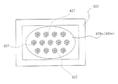
本実施例の可変形状鏡は、図15に示すように、薄膜409aと電極409bとの間に圧電素子409cが介装されていて、これらが支持台423上に設けられている。そして、圧電素子409cに加わる電圧を各電極409b毎に変えることにより、圧電素子409cに部分的に異なる伸縮を生じさせて、薄膜409aの形状を変えることができるようになっている。電極409bの形は、図16に示すように、同心分割であってもよいし、図17に示すように、矩形分割であってもよく、その他、適宜の形のものを選択することができる。図15中、424は演算装置414に接続された振れ(ブレ)センサーであって、例えばデジタルカメラの振れを検知し、振れによる像の乱れを補償するように薄膜409aを変形させるべく、演算装置414及び可変抵抗器411を介して電極409bに印加される電圧を変化させる。このとき、温度センサー415、湿度センサー416及び距離センサー417からの信号も同時に考慮され、ピント合わせ、温湿度補償等が行われる。この場合、薄膜409aには圧電素子409cの変形に伴う応力が加わるので、薄膜409aの厚さはある程度厚めに作られて相応の強度を持たせるようにするのがよい。
【0131】
図18は、本発明のズーム光学系の反射光学素子として適用可能な可変形状鏡409のさらに他の実施例を示す概略構成図である。
【0132】
本実施例の可変形状鏡は、薄膜409aと電極409bの間に介置される圧電素子が逆方向の圧電特性を持つ材料で作られた2枚の圧電素子409c及び409c’で構成されている点で、図15に示された実施例の可変形状鏡とは異なる。すなわち、圧電素子409cと409c’が強誘電性結晶で作られているとすれば、結晶軸の向きが互いに逆になるように配置される。この場合、圧電素子409cと409c’は電圧が印加されると逆方向に伸縮するので、薄膜409aを変形させる力が図15に示した実施例の場合よりも強くなり、結果的にミラー表面の形を大きく変えることができるという利点がある。
【0133】
圧電素子409c、409c’に用いる材料としては、例えばチタン酸バリウム、ロッシエル塩、水晶、電気石、リン酸二水素カリウム(KDP)、リン酸二水素アンモニウム(ADP)、ニオブ酸リチウム等の圧電物質、同物質の多結晶体、同物質の結晶、PbZrO3 とPbTiO3 の固溶体の圧電セラミックス、二フッ化ポリビニール(PVDF)等の有機圧電物質、上記以外の強誘電体等があり、特に有機圧電物質はヤング率が小さく、低電圧でも大きな変形が可能であるので、好ましい。なお、これらの圧電素子を利用する場合、厚さを不均一にすれば、上記実施例において薄膜409aの形状を適切に変形させることも可能である。
【0134】
また、圧電素子409c、409c’の材質としては、ポリウレタン、シリコンゴム、アクリルエラストマー、PZT、PLZT、ポリフッ化ビニリデン(PVDF)等の高分子圧電体、シアン化ビニリデン共重合体、ビニリデンフルオライドとトリフルオロエチレンの共重合体等が用いられる。
【0135】
圧電性を有する有機材料や、圧電性を有する合成樹脂、圧電性を有するエラストマー等を用いると可変形状鏡面の大きな変形が実現できてよい。
【0136】
なお、図15、図18の圧電素子409cに電歪材料、例えば、アクリルエラストマー、シリコンゴム等を用いる場合には、圧電素子409cを別の基板409c−1と電歪材料409c−2を貼り合わせた構造にしてもよい。
【0137】
図19は、本発明のズーム光学系の反射光学素子として適用可能な可変形状鏡409のさらに他の実施例を示す概略構成図である。
【0138】
本実施例の可変形状鏡は、圧電素子409cが薄膜409aと電極409dとにより挟持され、薄膜409aと電極409d間に演算装置414により制御される駆動回路425を介して電圧が印加されるようになっており、さらにこれとは別に、支持台423上に設けられた電極409bにも演算装置414により制御される駆動回路425を介して電圧が印加されるように構成されている。したがって、本実施例では、薄膜409aは電極409dとの間に印加される電圧と電極409bに印加される電圧による静電気力とにより二重に変形され得、上記実施例に示した何れのものよりもより多くの変形パターンが可能であり、かつ、応答性も速いという利点がある。
【0139】
そして、薄膜409a、電極409d間の電圧の符号を変えれば、可変形状鏡を凸面にも凹面にも変形させることができる。その場合、大きな変形を圧電効果で行い、微細な形状変化を静電気力で行ってもよい。また、凸面の変形には圧電効果を主に用い、凹面の変形には静電気力を主に用いてもよい。なお、電極409dは電極409bのように複数の電極から構成されてもよい。この様子を図19に示した。なお、本願では、圧電効果と電歪効果、電歪を全てまとめて圧電効果と述べている。したがって、電歪材料も圧電材料に含むものとする。
【0140】
図20は、本発明のズーム光学系の反射光学素子として適用可能な可変形状鏡409のさらに他の実施例を示す概略構成図である。
【0141】
本実施例の可変形状鏡は、電磁気力を利用して反射面の形状を変化させ得るようにしたもので、支持台423の内部底面上には永久磁石426が、頂面上には窒化シリコン又はポリイミド等からなる基板409eの周縁部が載置固定されており、基板409eの表面にはアルミニウム等の金属コートで作られた薄膜409aが付設されていて、可変形状鏡409を構成している。基板409eの下面には複数のコイル427が配設されており、これらのコイル427はそれぞれ駆動回路428を介して演算装置414に接続されている。したがって、各センサー415、416、417、424からの信号によって演算装置414において求められる光学系の変化に対応した演算装置414からの出力信号により、各駆動回路428から各コイル427にそれぞれ適当な電流が供給されると、永久磁石426との間に働く電磁気力で各コイル427は反発又は吸着され、基板409e及び薄膜409aを変形させる。
【0142】
この場合、各コイル427はそれぞれ異なる量の電流を流すようにすることもできる。また、コイル427は1個でもよいし、永久磁石426を基板409eに付設しコイル427を支持台423の内部底面側に設けるようにしてもよい。また、コイル427はリソグラフィー等の手法で作るとよく、さらに、コイル427には強磁性体よりなる鉄心を入れるようにしてもよい。
【0143】
この場合、薄膜コイル427の巻密度を、図21に示すように、場所によって変化させることにより、基板409e及び薄膜409aに所望の変形を与えるようにすることもできる。また、コイル427は1個でもよいし、また、これらのコイル427には強磁性体よりなる鉄心を挿入してもよい。
【0144】
図22は、本発明のズーム光学系の反射光学素子として適用可能な可変形状鏡409のさらに他の実施例を示す概略構成図である。図中、412は電源である。
【0145】
本実施例の可変形状鏡では、基板409eは鉄等の強磁性体で作られており、反射膜としての薄膜409aはアルミニウム等からなっている。この場合、薄膜コイルを設けなくてもすむから、構造が簡単で、製造コストを低減することができる。また、電源スイッチ413を切換え兼電源開閉用スイッチに置換すれば、コイル427に流れる電流の方向を変えることができ、基板409e及び薄膜409aの形状を自由に変えることができる。図23は、本実施例におけるコイル427の配置を示し、図24は、コイル427の他の配置例を示しているが、これらの配置は、図20に示した実施例にも適用することができる。なお、図25は、図20に示した実施例において、コイル427の配置を図24に示したようにした場合に適する永久磁石426の配置を示している。すなわち、図25に示すように、永久磁石426を放射状に配置すれば、図20に示した実施例に比べて、微妙な変形を基板409e及び薄膜409aに与えることができる。また、このように電磁気力を用いて基板409e及び薄膜409aを変形させる場合(図20及び図22の実施例)は、静電気力を用いた場合よりも低電圧で駆動できるという利点がある。
【0146】
以上、いくつかの可変形状鏡の実施例を述べたが、ミラーの形を変形させるのに、図19の例に示すように、2種類以上の力を用いてもよい。つまり静電気力、電磁力、圧電効果、磁歪、流体の圧力、電場、磁場、温度変化、電磁波等の中から2つ以上を同時に用いて可変形状鏡を変形させてもよい。つまり、2つ以上の異なる駆動方法を用いて光学特性可変光学素子を作れば、大きな変形と微細な変形とを同時に実現でき、精度の良い鏡面が実現できる。
【0147】
さて、以上のような本発明のズームレンズは、ズームレンズからなる結像光学系で物体像を形成しその像をCCDや銀塩フィルムといった撮像素子に受光させて撮影を行う撮影装置、とりわけデジタルカメラやビデオカメラ、情報処理装置の例であるパソコン、電話、特に持ち運びに便利な携帯電話等に用いることができる。以下に、その実施形態を例示する。
【0148】
図26〜図28は、本発明によるズームレンズをデジタルカメラの撮影光学系41に組み込んだ構成の概念図を示す。図26はデジタルカメラ40の外観を示す前方斜視図、図27は同後方斜視図、図28はデジタルカメラ40の構成を示す断面図である。デジタルカメラ40は、この例の場合、撮影用光路42を有する撮影光学系41、ファインダー用光路44を有するファインダー光学系43、シャッター45、フラッシュ46、液晶表示モニター47等を含み、カメラ40の上部に配置されたシャッター45を押圧すると、それに連動して撮影光学系41、例えば実施例1の光路折り曲げズームレンズを通して撮影が行われる。撮影光学系41によって形成された物体像が、近赤外カットフィルターと光学的ローパスフィルターLFを介してCCD49の撮像面上に形成される。このCCD49で受光された物体像は、処理手段51を介し、電子画像としてカメラ背面に設けられた液晶表示モニター47に表示される。また、この処理手段51には記録手段52が接続され、撮影された電子画像を記録することもできる。なお、この記録手段52は処理手段51と別体に設けてもよいし、フロッピーディスクやメモリーカード、MO等により電子的に記録書込を行うように構成してもよい。また、CCD49に代わって銀塩フィルムを配置した銀塩カメラとして構成してもよい。
【0149】
さらに、ファインダー用光路44上にはファインダー用対物光学系53が配置してある。このファインダー用対物光学系53によって形成された物体像は、像正立部材であるポロプリズム55の視野枠57上に形成される。このポリプリズム55の後方には、正立正像にされた像を観察者眼球Eに導く接眼光学系59が配置されている。なお、撮影光学系41及びファインダー用対物光学系53の入射側、接眼光学系59の射出側にそれぞれカバー部材50が配置されている。
【0150】
このように構成されたデジタルカメラ40は、撮影光学系41が広画角で高変倍比であり、収差が良好で、明るく、フィルター等が配置できるバックフォーカスの大きなズームレンズであるので、高性能・低コスト化が実現できる。
【0151】
なお、図28の例では、カバー部材50として平行平面板を配置しているが、パワーを持ったレンズを用いてもよい。
【0152】
次に、本発明のズームレンズが対物光学系として内蔵された情報処理装置の一例であるパソコンが図29〜図31に示される。図29はパソコン300のカバーを開いた前方斜視図、図30はパソコン300の撮影光学系303の断面図、図31は図29の状態の側面図である。図29〜図31に示されるように、パソコン300は、外部から繰作者が情報を入力するためのキーボード301と、図示を省略した情報処理手段や記録手段と、情報を操作者に表示するモニター302と、操作者自身や周辺の像を撮影するための撮影光学系303とを有している。ここで、モニター302は、図示しないバックライトにより背面から照明する透過型液晶表示素子や、前面からの光を反射して表示する反射型液晶表示素子や、CRTディスプレイ等であってよい。また、図中、撮影光学系303は、モニター302の右上に内蔵されているが、その場所に限らず、モニター302の周囲や、キーボード301の周囲のどこであってもよい。
【0153】
この撮影光学系303は、撮影光路304上に、本発明による例えば実施例1の光路折り曲げズームレンズからなる対物レンズ112と、像を受光する撮像素子チップ162とを有している。これらはパソコン300に内蔵されている。
【0154】
ここで、撮像素子チップ162上には光学的ローパスフィルターLFが付加的に貼り付けられて撮像ユニット160として一体に形成され、対物レンズ112の鏡枠113の後端にワンタッチで嵌め込まれて取り付け可能になっているため、対物レンズ112と撮像素子チップ162の中心合わせや面間隔の調整が不要であり、組立が簡単となっている。また、鏡枠113の先端(図示略)には、対物レンズ112を保護するためのカバーガラス114が配置されている。なお、鏡枠113中のズームレンズの駆動機構等は図示を省いてある。
【0155】
撮像素子チップ162で受光された物体像は、端子166を介して、パソコン300の処理手段に入力され、電子画像としてモニター302に表示される、図29には、その一例として、操作者の撮影された画像305が示されている。また、この画像305は、処理手段を介し、インターネットや電話を介して、遠隔地から通信相手のパソコンに表示されることも可能である。
【0156】
次に、本発明のズームレンズが撮影光学系として内蔵された情報処理装置の一例である電話、特に持ち運びに便利な携帯電話が図32に示される。図32(a)は携帯電話400の正面図、図32(b)は側面図、図32(c)は撮影光学系405の断面図である。図32(a)〜(c)に示されるように、携帯電話400は、操作者の声を情報として入力するマイク部401と、通話相手の声を出力するスピーカ部402と、操作者が情報を入力する入力ダイアル403と、操作者自身や通話相手等の撮影像と電話番号等の情報を表示するモニター404と、撮影光学系405と、通信電波の送信と受信を行うアンテナ406と、画像情報や通信情報、入力信号等の処理を行う処理手段(図示せず)とを有している。ここで、モニター404は液晶表示素子である。また、図中、各構成の配置位置は、特にこれらに限られない。この撮影光学系405は、撮影光路407上に配置された本発明による例えば実施例1の光路折り曲げズームレンズからなる対物レンズ112と、物体像を受光する撮像素子チップ162とを有している。これらは、携帯電話400に内蔵されている。
【0157】
ここで、撮像素子チップ162上には光学的ローパスフィルターLFが付加的に貼り付けられて撮像ユニット160として一体に形成され、対物レンズ112の鏡枠113の後端にワンタッチで嵌め込まれて取り付け可能になっているため、対物レンズ112と撮像素子チップ162の中心合わせや面間隔の調整が不要であり、組立が簡単となっている。また、鏡枠113の先端(図示略)には、対物レンズ112を保護するためのカバーガラス114が配置されている。なお、鏡枠113中のズームレンズの駆動機構等は図示を省いてある。
【0158】
撮影素子チップ162で受光された物体像は、端子166を介して、図示していない処理手段に入力され、電子画像としてモニター404に、又は、通信相手のモニターに、又は、両方に表示される。また、通信相手に画像を送信する場合、撮像素子チップ162で受光された物体像の情報を、送信可能な信号へと変換する信号処理機能が処理手段には含まれている。
【0159】
以上の本発明のズームレンズとそれを用いた電子撮像装置は例えば次のように構成することができる。
【0160】
〔1〕 物体側から順に、負レンズと光路を折り曲げるための反射光学素子を含んでおり変倍時に固定であるレンズ群A、広角端から望遠端に変倍する際に一方向にのみ移動するレンズ群B、変倍時に位置が不動の開口絞りを有し、以下の条件を満足することを特徴とするズームレンズ。
【0161】
(1) 0.45<log γB /log γ<0.85
ただし、γ、γB はそれぞれ、
γ=fT /fW
γB =望遠端におけるレンズ群Bの倍率/広角端におけるレンズ群Bの倍率とし、fW 、fT はそれぞれズームレンズ全系の広角端、望遠端の焦点距離とする。
【0162】
〔2〕 広角端から望遠端に変倍する際、前記開口絞りよりも像側に、一方向にのみ移動するレンズ群を有することを特徴とする上記1記載のズームレンズ。
【0163】
〔3〕 物体側から順に、負の屈折力であり変倍時に固定であるレンズ群A、正の屈折力であり変倍時に移動するレンズ群B、変倍時に位置が不動の開口絞りを有し、以下の条件を満足することを特徴とするズームレンズ。
【0164】
(1) 0.45<log γB /log γ<0.85
ただし、γ、γB はそれぞれ、
γ=fT /fW
γB =望遠端におけるレンズ群Bの倍率/広角端におけるレンズ群Bの倍率とし、fW 、fT はそれぞれズームレンズ全系の広角端、望遠端の焦点距離とする。
【0165】
〔4〕 前記開口絞りから像側に向かって順に、負の屈折力であるレンズ群C、正の屈折力であるレンズ群Dを有し、広角端から望遠端に変倍する際に、少なくとも一方のレンズ群が像側にのみ移動することを特徴とする上記3記載のズームレンズ。
【0166】
〔5〕 前記レンズ群Aには光路を折り曲げるための反射光学素子を含んでおり、前記レンズ群Bは広角端から望遠端に変倍する際に物体側にのみ移動することを特徴とする上記3又は4記載のズームレンズ。
【0167】
〔6〕 前記レンズ群Aは、物体側に凸面を有する負メニスカスレンズを有する副群A1、光路を折り曲げるための反射光学素子、少なくとも正レンズを含む副群A2からなることを特徴とする上記1から5の何れか1項記載のズームレンズ。
【0168】
〔7〕 前記開口絞りより像側の何れかのレンズ群にて合焦を行うようにしたことを特徴とする上記1から6の何れか1項記載のズームレンズ。
【0169】
〔8〕 正の屈折力を有する全てのレンズ群に非球面を有することを特徴とする上記1から7の何れか1項記載のズームレンズ。
【0170】
〔9〕 正の屈折力を有する全てのレンズ群が接合レンズ成分を含むことを特徴とする上記1から8の何れか1項記載のズームレンズ。
【0171】
〔10〕 正の屈折力を有する全てのレンズ群が1つの接合レンズ成分のみで構成されていることを特徴とする上記1から9の何れか1項記載のズームレンズ。
【0172】
〔11〕 光路を折り曲げるための反射光学素子が以下の媒質条件を満たすプリズムブロックで構成されていることを特徴とする上記1から10の何れか1項記載のズームレンズ。
ズームレンズ
(2) 1.55<npri <1.97
ただし、npri はプリズムブロックのd線に対する媒質の屈折率である。
【0173】
〔12〕 前記プリズムブロックは以下の条件を満たすことを特徴とする上記11記載のズームレンズ。
【0174】
(3) 0.5<d/L<1.2
ただし、dはプリズムブロックの光線入射面から光線射出面まで光軸に沿って測ったときの空気換算長、Lは撮像素子の有効撮像領域の対角長とする。
【0175】
〔13〕 望遠端におけるレンズ群Bの以降の合成倍率が以下の条件を満たすことを特徴とする上記3から12の何れか1項記載のズームレンズ。
【0176】
(4) 0.75<−βRt<1.5
ただし、βRtはレンズ群B以降の望遠端における合成倍率(無限遠物点)である。
【0177】
〔14〕 無限遠合焦時に広角端から望遠端変倍する際のレンズ群の移動量が以下の条件を満たすことを特徴とする上記4から13の何れか1項記載のズームレンズ。
【0178】
(5) −1.0<M3 /M2 <−0.3
ただし、M2 、M3 はそれぞれレンズ群B、レンズ群Cの移動量である。
【0179】
〔15〕 無限遠合焦時に広角端から望遠端変倍する際のレンズ群の移動量が以下の条件を満たすことを特徴とする上記4から14の何れか1項記載のズームレンズ。
【0180】
(6) 0.3<M4 /M3 <0.9
ただし、M3 、M4 はそれぞれレンズ群C、レンズ群Dの移動量である。
【0181】
〔16〕 前記レンズ群Aの副群A2は、物体側から順に、正レンズ・負レンズの2枚で構成され、以下の条件を満たすことを特徴とする上記6から15の何れか1項記載のズームレンズ。
【0182】
(7) −0.3<L/f12<0
ただし、f12はレンズ群Aの副群A2の焦点距離、Lは撮像素子の有効撮像領域の対角長とする。
【0183】
〔17〕 前記レンズ群Aが以下の条件を満たすことを特徴とする上記6から16の何れか1項記載のズームレンズ。
【0184】
(8) 0.5<(R11F +R11R )/(R11F −R11R )<4.5
(9) 0<f11/f12<0.8
ただし、R11F 、R11R はそれぞれレンズ群Aの副群A1の負レンズの物体側の面、 像側の面の光軸上での曲率半径、f11、f12はそれぞれレンズ群Aの副群A1、A2の焦点距離である。
【0185】
〔18〕 前記光路を折り曲げるための反射光学素子が形状制御可能な形状可変ミラーからなることを特徴とする上記1から2、5から17の何れか1項記載のズームレンズ。
【0186】
〔19〕 上記1から18の何れか1項記載のズームレンズと、その像側に配置された電子撮像素子とを備えたことを特徴とする電子撮像装置。
【0187】
【発明の効果】
本発明により、物体側にミラー等の反射光学素子を挿入して光学系、特にズームレンズ系の光路(光軸)を折り曲げる構成とし、諸々の工夫を入れることにより、高ズーム比、広画角、小さいF値、少ない収差等、極力高い光学仕様性能を確保しながらも、沈胴式鏡筒に見られるようなカメラの使用状態への立ち上げ時間(レンズのせり出し時間)がなく、防水・防塵上も好ましく、また、奥行き方向が極めて薄いカメラとすることが可能となる。加えて、絞り、シャッター機構等を移動させない光学系とすることにより、奥行きをさらに薄くすることができる。
【図面の簡単な説明】
【図1】本発明のズームレンズの実施例1の無限遠物点合焦時の広角端(a)、中間状態(b)、望遠端(c)でのレンズ断面図である。
【図2】実施例2のズームレンズの図1と同様のレンズ断面図である。
【図3】実施例3のズームレンズの図1と同様のレンズ断面図である。
【図4】実施例4のズームレンズの図1と同様のレンズ断面図である。
【図5】実施例1のズームレンズの広角端無限遠物点合焦時の折り曲げ時における光路図である。
【図6】実施例1の無限遠物点合焦時の収差図である。
【図7】実施例2の無限遠物点合焦時の収差図である。
【図8】実施例3の無限遠物点合焦時の収差図である。
【図9】実施例4の無限遠物点合焦時の収差図である。
【図10】電子撮像素子にて撮影を行う場合の有効撮像面の対角長について説明するための図である。
【図11】近赤外シャープカットコートの一例の透過率特性を示す図である。
【図12】ローパスフィルターの射出面側に設ける色フィルターの一例の透過率特性を示す図である。
【図13】補色モザイクフィルターの色フィルター配置を示す図である。
【図14】補色モザイクフィルターの波長特性の一例を示す図である。
【図15】本発明のズーム光学系の反射光学素子として適用可能な可変形状鏡の1実施例を示す概略構成図である。
【図16】図15の実施例の可変形状鏡に用いる電極の1形態を示す説明図である。
【図17】図15の実施例の可変形状鏡に用いる電極の他の形態を示す説明図である。
【図18】本発明のズーム光学系の反射光学素子として適用可能な可変形状鏡のさらに他の実施例を示す概略構成図である。
【図19】本発明のズーム光学系の反射光学素子として適用可能な可変形状鏡のさらに他の実施例を示す概略構成図である。
【図20】本発明のズーム光学系の反射光学素子として適用可能な可変形状鏡のさらに他の実施例を示す概略構成図である。
【図21】図20の実施例における薄膜コイルの巻密度の状態を示す説明図である。
【図22】本発明のズーム光学系の反射光学素子として適用可能な可変形状鏡のさらに他の実施例を示す概略構成図である。
【図23】図22の実施例におけるコイルの1配置例を示す説明図である。
【図24】図22の実施例におけるコイルの他の配置例を示す説明図である。
【図25】図20に示した実施例において、コイルの配置を図24に示したようにした場合に適する永久磁石の配置を示す説明図である。
【図26】本発明による光路折り曲げズーム光学系を組み込んだデジタルカメラの外観を示す前方斜視図である。
【図27】図26のデジタルカメラの後方斜視図である。
【図28】図26のデジタルカメラの断面図である。
【図29】本発明による光路折り曲げズーム光学系を対物光学系として組み込れたパソコンのカバーを開いた前方斜視図である。
【図30】パソコンの撮影光学系の断面図である。
【図31】図29の状態の側面図である。
【図32】本発明による光路折り曲げズーム光学系を対物光学系として組み込れた携帯電話の正面図、側面図、その撮影光学系の断面図である。
【符号の説明】
G1…第1レンズ群
G2…第2レンズ群
G3…第3レンズ群
G4…第4レンズ群
S…絞り
LF…光学的ローパスフィルター
CG…CCDのカバーガラス
I…CCDの像面
P…光路折り曲げプリズム(平行平板)
E…観察者眼球
40…デジタルカメラ
41…撮影光学系
42…撮影用光路
43…ファインダー光学系
44…ファインダー用光路
45…シャッター
46…フラッシュ
47…液晶表示モニター
49…CCD
50…カバー部材
51…処理手段
52…記録手段
53…ファインダー用対物光学系
55…ポロプリズム
57…視野枠
59…接眼光学系
112…対物レンズ
113…鏡枠
114…カバーガラス
160…撮像ユニット
162…撮像素子チップ
166…端子
300…パソコン
301…キーボード
302…モニター
303…撮影光学系
304…撮影光路
305…画像
400…携帯電話
401…マイク部
402…スピーカ部
403…入力ダイアル
404…モニター
405…撮影光学系
406…アンテナ
407…撮影光路
409…可変形状鏡(光学特性可変形状鏡)
409a…薄膜(反射面)
409b…電極
409c…圧電素子
409c’…圧電素子
409c−1…基板
409c−2…電歪材料
409d…電極
409e…基板
411…可変抵抗器
412…電源
413…電源スイッチ
414…演算装置
415…温度センサー
416…湿度センサー
417…距離センサー
423…支持台
424…振れ(ブレ)センサー
425…駆動回路
426…永久磁石
427…コイル
428…駆動回路[0001]
BACKGROUND OF THE INVENTION
The present invention relates to a zoom lens and an electronic image pickup apparatus using the same, and more particularly to an electronic image pickup apparatus such as a video camera or a digital camera that is thinned in the depth direction by devising an optical system part such as a zoom lens. Is.
[0002]
[Prior art]
In recent years, a digital camera (electronic camera) has attracted attention as a next-generation camera that replaces a silver salt 35 mm film (135 format) camera. Furthermore, it has come to have a number of categories in a wide range from a high-function type for business use to a portable popular type.
[0003]
In the present invention, focusing on the portable popular type category, it is aimed to provide a technology for realizing a video camera and a digital camera that are thin and easy to use while ensuring high image quality. The biggest bottleneck in reducing the depth direction of the camera is the thickness from the most object-side surface to the imaging surface of the optical system, particularly the zoom lens system.
[0004]
The mainstream of the recent camera body thinning technology is to employ a so-called collapsible lens barrel that has an optical system that protrudes from the camera body at the time of photographing, but is housed when it is carried. Examples of optical systems that can be effectively thinned by employing a retractable lens barrel include those disclosed in JP-A-11-194274, JP-A-11-287953, JP-A-2000-9997, and the like. These have, in order from the object side, a first group having a negative refractive power and a second group having a positive refractive power, and both move during zooming. However, if a retractable lens barrel is employed, it takes time to start from the lens storage state to the use state, which is not preferable in terms of convenience. Further, if the lens group closest to the object is movable, it is not preferable in terms of waterproofing and dustproofing.
[0005]
[Problems to be solved by the invention]
The present invention has been made in view of such problems of the prior art, and its object is to eliminate the time for starting up the camera (the lens protruding time) as seen in a retractable lens barrel. It is also preferable for waterproofing and dustproofing, and it is easy to bend the optical path (optical axis) of the optical system with a reflective optical element such as a mirror to make the camera extremely thin in the depth direction, with a high zoom ratio and wide angle of view. It is to provide a zoom lens having a high optical specification performance such as a small F value and a small aberration.
[0006]
[Means for Solving the Problems]
In order to achieve the above object, the zoom lens of the present invention includes, in order from the object side, a negative lens and a reflective optical element for bending the optical path, and is fixed at the time of zooming, from the wide-angle end to the telephoto end. The lens group B moves only in one direction when zooming, and has an aperture stop whose position does not move when zooming, and satisfies the following conditions.
[0007]
(1) 0.45 <log γB/ Log γ <0.85
However, γ, γBRespectively
γ = fT/ FW
γB= Magnification of lens group B at the telephoto end / magnification of lens group B at the wide-angle end, fW, FTAre the focal lengths at the wide-angle end and the telephoto end of the entire zoom lens system.
[0008]
Below, the reason and effect | action which take the said structure in this invention are demonstrated.
[0009]
In order to achieve the above object, in the present invention, a lens group A that includes a negative lens and a reflective optical element for bending the optical path and is fixed at the time of zooming, is used when zooming from the wide-angle end to the telephoto end. A zoom lens having a lens group B that moves only in the direction and an aperture stop that does not move during zooming is employed.
[0010]
In this way, the reflecting optical element for bending the optical path is provided in the lens group A closest to the object side, and further, the lens group A having a bending function is fixed at the time of zooming in order to avoid mechanical complexity. Thus, the depth direction of the camera can be reduced. In order to obtain a camera with a very thin depth direction, it is necessary to consider that the lens barrel is not enlarged in the lens radial direction on the image side with respect to the optical path bending portion. For example, if the aperture mechanism (which may include a shutter mechanism) is moved at the same time as zooming, the light quantity adjustment control mechanism is also moved together, and the lens barrel is enlarged in the radial direction to secure the movement space It will become.
[0011]
Therefore, in the present invention, the aperture mechanism position is fixed during zooming.
[0012]
However, if the aperture stop is fixed on the object side of the lens group that moves in one direction during zooming and contributes greatly to zooming, the amount of change in the F value from the wide-angle end to the telephoto end is extremely large. Therefore, it is necessary to dispose at least the lens group that contributes to zooming toward the object side relative to the stationary aperture stop, that is, the lens group B that moves only in one direction when zooming from the wide-angle end to the telephoto end. On the other hand, if the amount of movement of the lens group B is large, the entrance pupil becomes deep and the optical path is not bent, and telecentricity on the exit side cannot be satisfied. Is limited to the range of the condition (1).
[0013]
(1) 0.45 <log γB/ Log γ <0.85
However, γ, γBRespectively
γ = fT/ FW
γB= Magnification of lens group B at the telephoto end / magnification of lens group B at the wide-angle end, fW, FTAre the focal lengths at the wide-angle end and the telephoto end of the entire zoom lens system.
[0014]
When the upper limit of 0.85 of the condition (1) is exceeded, the entrance pupil becomes deep, and the establishment of optical path bending and the telecentricity on the exit side tend to be hindered. If the lower limit of 0.45 is exceeded, the zoom ratio cannot be achieved, or if the zoom ratio is supplemented by the lens group behind the aperture stop, the greater the amount of reinforcement, the longer the distance from the wide-angle end to the telephoto end. The amount of change in the F value increases. Note that the amount of change in the F-number is small if the reinforcement is to some extent, so when zooming from the wide-angle end to the telephoto end on the image side of the aperture stop, a lens group that moves only in one direction (contributes to zooming). A lens group).
[0015]
It is better to do the following.
[0016]
(1) ′ 0.5 <log γB/ Log γ <0.8
Furthermore, it is best to do the following.
[0017]
(1) "0.55 <log γB/ Log γ <0.77
Incidentally, when the lens group A has a negative refractive power, the lens group B has a positive refractive power, and when the lens group A has a positive refractive power, the lens group B has a negative refractive power. . In the latter case, the image side from the aperture stop has a lens group C having a positive refractive power and a lens group D having a positive refractive power in the order of the optical path, and when zooming from the wide angle end to the telephoto end, The zoom ratio is reinforced by moving the lens group D only to the image side. The former case will be described later. Further, the lens group B on the object side and the lens group C on the image side of the aperture stop have different refractive powers.
[0018]
In addition, as a price for securing the space by bending the optical path, the entrance pupil may become deeper or it may be difficult to secure the zoom ratio. If possible, the reflective optical element for bending the optical path should be a prism block that satisfies the following medium conditions. It is good to do.
[0019]
(2) 1.55 <npri<1.97
Where npriIs the refractive index of the medium with respect to the d-line when the reflecting optical element for bending the optical path of the lens group A is a prism.
[0020]
If the lower limit of 1.55 in conditional expression (2) is exceeded, the optical element on the object side including the prism tends to be large, which is disadvantageous in terms of aberration correction, and the combined magnification of the groups after the lens group B becomes low. The amount of movement of the lens group B increases or it becomes difficult to ensure a high zoom ratio. If the upper limit of 1.97 is exceeded, the cost of the prism increases.
[0021]
It is better to do the following.
[0022]
(2) '1.65 <npri<1.95
Furthermore, it is best to do the following.
[0023]
(2) "1.75 <npri<1.93
The lens group A is preferably composed of a sub group A1 having a negative meniscus lens having a convex surface on the object side, a reflective optical element for bending the optical path, and a sub group A2 including at least a positive lens.
[0024]
In order to correct off-axis aberrations such as chromatic aberration and distortion, the subgroup A2 is preferably composed of two negative lenses and positive lenses in order from the object side, and satisfies the following conditions.
[0025]
When it is defined by the air conversion length d measured along the optical axis from the light incident surface to the light exit surface of the prism block of the lens group A, the following is preferable.
[0026]
(3) 0.5 <d / L <1.2
However, L is the diagonal length of the effective imaging area (substantially rectangular) of the imaging device.
[0027]
If the upper limit of 1.2 of the condition (3) is exceeded, the optical element on the object side including the prism tends to be large, which is disadvantageous in terms of aberration correction, and the combined magnification of the lens group B and subsequent groups becomes low. The amount of movement of the lens group B increases or it becomes difficult to ensure a high zoom ratio. When the lower limit of 0.5 is exceeded, the luminous flux contributing to the image formation at the periphery of the image does not reach the image plane satisfactorily, or ghosts are likely to occur. If this condition can be satisfied, the medium before and after reflection may be an air surface mirror.
[0028]
Further, when the direction of bending the optical path is the long side direction of the effective screen and the short side direction, the following ranges are preferable.
[0029]
(3-1) 0.75 <d / L <1.1
(3-2) 0.55 <d / L <0.9
Furthermore, it is best to do the following respectively.
[0030]
(3-1) '0.8 <d / L <1.0
(3-2) '0.6 <d / L <0.8
In addition, it is advantageous in terms of downsizing and aberration correction of the optical element on the object side including the prism, that the reflecting optical element for bending the optical path is constituted by a prism of a medium having a high refractive index.
[0031]
The zoom lens of the present invention is characterized in that the lens unit closest to the object side is fixed at the time of zooming, and further, the aperture position can also be fixed. Satisfying (1) is the most important feature.
[0032]
When the lens unit A closest to the object along the optical path has a negative refractive power, the lens unit B has a positive refractive power. In this case as well, it is desirable to satisfy the condition (1). Furthermore, in order to reduce the moving amount of each lens unit as much as possible and shorten the optical total length, the magnification of the synthesis system after the lens unit B is changed in the vicinity of −1 as in the following condition (4). It is good. However, a lower absolute value of magnification is advantageous for aberration correction. Therefore, the following conditions should be satisfied at the telephoto end.
[0033]
(4) 0.75 <−βRt<1.5
However, βRtIs the combined magnification (object point at infinity) at the telephoto end after the lens group B.
[0034]
Even if the upper limit of 1.5 and the lower limit of 0.75 of the condition (4) are both exceeded, the amount of change in the relative distance between the lens groups tends to be large and the optical total length tends to be long.
[0035]
It is better to do the following.
[0036]
(4) ′ 0.8 <−βRt<1.3
Furthermore, it is best to do the following.
[0037]
(4) "0.85 <-βRt<1.15
In addition, on the image side from the aperture stop, there is a lens group C having a negative refractive power and a lens group D having a positive refractive power in order of the optical path, and at least when zooming from the wide angle end to the telephoto end. It is desirable to reinforce the zoom ratio by moving one lens group only to the image side.
[0038]
Further, the lens group B on the object side and the lens group C on the image side with respect to the aperture stop have different refractive powers, so that they move in opposite directions at the time of zooming. The amount of movement M of each of the lens unit B and the lens unit C when zooming from the telephoto end to the telephoto end2 , MThree The ratio is preferably as in the following condition (5).
[0039]
(5) -1.0 <MThree / M2 <-0.3
If the upper limit of -0.3 of the condition (5) is exceeded, the entrance pupil becomes deep, and the establishment of optical path bending and the telecentricity on the exit side are likely to be hindered. When the lower limit of −1.0 is exceeded, the amount of change in the F value from the wide-angle end to the telephoto end increases.
[0040]
It is better to do the following.
[0041]
(5) '-0.9 <MThree / M2 <-0.4
Furthermore, it is best to do the following.
[0042]
(5) "-0.85 <MThree / M2 <-0.5
Further, focusing is preferably performed by any lens group on the image side from the aperture stop.
[0043]
In addition, the amount of movement M of each of the lens unit C and the lens unit D when zooming from the wide-angle end to the telephoto end during infinite focus is achieved.Three, MFourThe ratio is preferably as in the following condition (6).
[0044]
(6) 0.3 <MFour/ MThree<0.9
If the upper limit of 0.9 of the condition (6) is exceeded, it will be difficult to increase the zoom ratio. If the lower limit of 0.3 is exceeded, it will be difficult to secure a moving space for focusing.
[0045]
It is better to do the following.
[0046]
(6) '0.4 <MFour/ MThree<0.8
Furthermore, it is best to do the following.
[0047]
(6) "0.5 <MFour/ MThree<0.7
By the way, as described above, the lens group A may be composed of the sub group A1 having a negative meniscus lens having a convex surface on the object side, the reflecting optical element for bending the optical path, and the sub group A2 including at least a positive lens. In particular, it is preferable that the subgroup A1 is composed of only one lens and that the subgroup A2 corrects aberrations such as chromatic aberration. In order to correct off-axis aberrations such as chromatic aberration and distortion, the sub-group A2 of the lens group A is preferably composed of two lenses, a positive lens and a negative lens, in order from the object side, and satisfies the following conditions.
[0048]
(7) -0.3 <L / f12<0
Where f12Is the focal length of the subgroup A2 of the lens group A.
[0049]
If the upper limit of 0 in the condition (7) is exceeded, the combined magnification of the groups after the lens group B becomes low, and the amount of movement of the lens group B increases or it becomes difficult to secure a high zoom ratio. If it exceeds .3, the object-side optical element including the prism tends to be large, which is disadvantageous in terms of aberration correction.
[0050]
It is better to do the following.
[0051]
(7) '-0.2 <L / f12<0
Furthermore, it is best to do the following.
[0052]
(7) "-0.1 <L / f12<0
As in the present invention, since the reflecting optical element for bending the optical path requires a certain amount of optical path length, the entrance pupil is likely to be deep, and the focal length after the lens group B is sufficient to ensure the magnification. It becomes long and the movement space tends to be large. Since both are contradictory, it is preferable that the negative refractive power of the lens group A is divided into two and dispersed before and after the reflecting optical element for bending the optical path. In that case, the following conditions should be satisfied.
[0053]
(8) 0.5 <(R11F+ R11R) / (R11F-R11R) <4.5
(9) 0 <f11/ F12<0.8
However, R11F, R11RIs the radius of curvature on the optical axis of the object side surface and the image side surface of the negative lens of the subgroup A1 of the lens group A, f11, F12Are the focal lengths of the subgroups A1 and A2 of the lens group A, respectively.
[0054]
Condition (8) defines the shape factor of the negative lens in the subgroup A1. If the upper limit of 4.5 is exceeded, it tends to interfere with the reflective optical element for bending the optical path, and avoiding this is not preferable because the depth dimension increases. Exceeding the lower limit of 0.5 makes it difficult to correct aberrations such as distortion.
[0055]
Condition (9) defines the focal length ratio between the subgroup A1 and the subgroup A2. When the upper limit of 0.8 is exceeded, the entrance pupil tends to become deeper, and when the lower limit of 0 is exceeded, the focal length after the lens group B becomes longer to secure the magnification, and the moving space tends to increase.
[0056]
Note that it is better to set one or both of the conditions (8) and (9) as follows.
[0057]
(8) ′ 0.8 <(R11F+ R11R) / (R11F-R11R<3.5
(9) ’0 <f11/ F12<0.5
Furthermore, it is better to set one or both of the conditions (8) and (9) as follows. In particular, it is best to do both as follows.
[0058]
(8) "1.0 <(R11F+ R11R) / (R11F-R11R<2.5
(9) "0 <f11/ F12<0.2
Moreover, in any type, in order to make the paraxial refractive power arrangement appropriate, the reflecting surface may be configured other than a plane. In addition, a control system that can freely change the shape of the reflecting surface is provided to correct the focal position and aberration fluctuations that occur when zooming due to the deformation, focus, and zooming. It is more preferable to use a shape-controllable mirror capable of shape control.
[0059]
Alternatively, the reflecting optical element may be formed by bonding a plano-concave lens to the prism plane, or the effective light passing surface or reflecting surface of the prism may be formed by a curved surface. A positive lens with the weakest power may be added to the object side from the relationship of the balance between the level of distortion correction and the target size of the electronic imaging apparatus. In that case, the subgroup A2 of the lens group A may not be provided. The sub group A1 of the lens group A is fixed at the time of zooming, but the sub group A2 may be movable because it is relatively easy to move. In that case, it is preferable to move while drawing a convex locus on the image side during zooming.
[0060]
Further, in order to reduce the size of the lens system, it is important to reduce the number of lenses and reduce the thickness of each lens element. In both cases, the degree of freedom in correcting Seidel aberrations and chromatic aberrations is lost, making correction difficult. First, with respect to each Seidel aberration, it is effective to introduce an aspherical surface into all lens groups having positive refractive power in order to correct the aberration fluctuation at the time of zooming and the off-axis residual aberration in the entire zooming range. Among these, it is particularly preferable to apply to a positive lens element. As for chromatic aberration, it is desirable that all lens groups having positive refractive power include a cemented lens component in order to correct axial and magnification chromatic aberration over the entire zooming range. From the viewpoint of reducing the number of lenses, it is preferable that all lens groups having a positive refractive power are composed of only one cemented lens component. In the present invention, the lens component means a single lens or a cemented lens, with a lens that is in contact with air only on the object side and the image side along the optical path as one unit.
[0061]
As described above, the means for improving the imaging performance while making the zoom lens portion thin has been provided.
[0062]
Next, mention is made of thinning filters. In an electronic imaging device, an infrared absorption filter having a certain thickness is usually inserted closer to the object side than the imaging device so that infrared light does not enter the imaging surface. Consider replacing this with a thin coating. Naturally, it will be thinner, but it has a side effect. The transmittance (τ) at a wavelength of 600 nm is located closer to the object side than the image sensor behind the zoom lens system.600) Is 80% or more and transmittance at 700 nm (τ)700) Of 8% or less near infrared sharp cut coat, the transmittance in the near infrared region of 700 nm or more is lower than that of the absorption type, and the transmittance on the red side is relatively high. The magenta tendency on the bluish-purple side, which is a defect of a solid-state image pickup device such as a CCD having the above, is alleviated by gain adjustment, and color reproduction similar to a solid-state image pickup device such as a CCD having a primary color filter can be obtained. Further, not only the primary color complementary color but also the color reproduction of those having a strong reflectance in the near infrared region such as plants and human skin.
[0063]
That is,
(10) τ600/ Τ550≧ 0.8
(11) τ700/ Τ550≦ 0.08
It is desirable to satisfy. Where τ550Is the transmittance at a wavelength of 550 nm.
[0064]
In addition, it is better to set one or both of the conditions (10) and (11) as follows.
[0065]
(10) ’τ600/ Τ550≧ 0.85
(11) ’τ700/ Τ550≦ 0.05
Furthermore, it is better to set one or both of the conditions (10) and (11) as follows. In particular, it is best to do both as follows.
[0066]
(10) “τ600/ Τ550≧ 0.9
(11) “τ700/ Τ550≦ 0.03
Another drawback of a solid-state imaging device such as a CCD is that the sensitivity to the near-ultraviolet wavelength of 550 nm is considerably higher than that of the human eye. This also highlights the color blur at the edge of the image due to chromatic aberration in the near ultraviolet region. In particular, it is fatal to downsize the optical system. Therefore, the transmittance at the wavelength of 400 nm (τ400) At 550 nm (τ)550) Ratio below 0.08, and transmittance at 440 nm (τ440) At 550 nm (τ)550) If an absorber or reflector with a ratio of more than 0.4 is inserted in the optical path, the wavelength range required for color reproduction is not lost (while maintaining good color reproduction), and noise such as color bleeding Is considerably reduced.
[0067]
That is,
(12) τ400/ Τ550≦ 0.08
(13) τ440/ Τ550≧ 0.4
It is desirable to satisfy.
[0068]
In addition, it is better to set one or both of the conditions (12) and (13) as follows.
[0069]
(12) ’τ400/ Τ550≦ 0.06
(13) ’τ440/ Τ550≧ 0.5
Furthermore, it is better to set one or both of the conditions (12) and (13) as follows. In particular, it is best to do both as follows.
[0070]
(12) “τ400/ Τ550≦ 0.04
(13) “τ440/ Τ550≧ 0.6
These filters are preferably installed between the imaging optical system and the image sensor.
[0071]
On the other hand, in the case of a complementary color filter, because of its high transmitted light energy, it is substantially more sensitive than a CCD with a primary color filter and is advantageous in terms of resolution. It is.
[0072]
In order to make the optical system short and thin, it is preferable to make the other low-pass optical filter as thin as possible. In general, the optical low-pass filter uses the birefringence action of a uniaxial crystal such as quartz, but the angle formed by the crystal axis with respect to the optical axis of the zoom lens is in the range of 35 ° to 55 °. In addition, when a plurality of or single crystal optical low-pass filters having different directions when each crystal axis is projected onto the image plane are included, the thickness t of the filter having the largest thickness along the optical axis of the zoom lens is included.LPF(Mm) should satisfy the following conditions.
[0073]
(14) 0.08 <tLPF/A<0.16 (when a <4 μm)
0.075 <tLPF/A<0.15 (when a <3 μm)
Where tLPF(Mm) is the thickness of the optical low-pass filter having the largest thickness along the optical axis of the zoom lens and having one crystal axis in the range of 35 ° to 55 °, and a is the horizontal pixel pitch of the electronic image sensor ( Unit μm).
[0074]
The thickest optical low-pass filter composed of one or a plurality of filters is set so that its thickness is theoretically zero at the Nyquist limit frequency, and is approximately a / 5.88 ( mm). If it is thicker than this, it is effective in preventing false signals such as moire fringes, but the resolution of the electronic image sensor cannot be fully exhibited, and if it is thin, false signals such as moire fringes cannot be sufficiently removed. However, false signals such as moiré fringes are also closely related to the imaging performance of photographic lenses such as zoom lenses, and when the imaging performance is high, false signals such as moiré fringes are likely to occur. It is better to set a little thicker in the opposite case.
[0075]
On the other hand, as the pixel pitch decreases, the contrast of frequency components that exceed the Nyquist limit decreases due to the diffraction effect of the imaging lens system, so that the generation of false signals such as moire fringes is reduced. Therefore, it is preferable that the thickness is made several percent to several tens of percent less than a / 5.88 (mm) because the contrast at a spatial frequency below the frequency corresponding to the Nyquist limit is improved.
[0076]
It is better to do the following.
[0077]
(14) ’0.075 <tLPF/A<0.15 (when a <4 μm)
0.07 <tLPF/A<0.14 (when a <3 μm)
Furthermore, it is best to do the following.
[0078]
(14) "0.07 <tLPF/A<0.14 (when a <4 μm)
0.065 <tLPF/A<0.13 (when a <3 μm)
In addition, when a <4 μm, the optical low-pass filter is difficult to process if it is too thin, so it is not so thin, that is, even if the upper limit of the conditions (14), (14) ′, (14) ″ is exceeded, There is another way to increase the spatial frequency (cutoff frequency) at which the contrast becomes zero, in which the angle formed by the crystal axis of the optical low-pass filter with respect to the optical axis of the zoom lens is in the range of 15 ° to 35 °. Alternatively, it may be set to 55 ° to 75 °, or the optical low-pass filter may be omitted depending on the case.In this angle range, the separation amount of the incident light into the ordinary ray and the extraordinary ray is around 45 °. When the angle is 0 ° or 90 °, the separation is not achieved (however, in the case of 90 °, there is a speed difference between the two and a phase difference occurs). The principle of the λ / 4 plate).
[0079]
Also, as described above, when the pixel pitch is reduced, the imaging performance at a high spatial frequency corresponding to the influence of diffraction is deteriorated, so that it is difficult to increase the F number. Therefore, the type of aperture stop used in the camera may be only two types, that is, a large aperture that is largely deteriorated due to geometric aberration and an aperture value near the diffraction limit. In that case, the optical low-pass filter described above is not necessary.
[0080]
Especially when the pixel pitch is small and the imaging performance at the time of opening is the best, as a means of regulating the incident light beam size on the imaging surface, the inner diameter is variable or a method of replacing with a different inner diameter is not used. An aperture stop having a fixed inner diameter may be used. In that case, at least one of the lens surfaces adjacent to the aperture stop has a convex surface facing the aperture stop, and if any one of the adjacent lens surfaces penetrates the inner diameter of the aperture stop, the lens surface is wasted. There is no space, which contributes to shortening the overall length of the optical system. The aperture stop is an optical element having a transmittance of 90% or less (preferably the entrance surface and the exit surface should be flat) in any space including the optical axis that is separated by one or more lens surfaces. Or a means for replacing with another optical element having a different transmittance.
[0081]
Alternatively, a plurality of apertures having a fixed aperture size are provided, and one of them is in any optical path between the lens surface closest to the image side of the lens group A and the lens surface closest to the object side of the lens group C. An electronic imaging device that can be inserted and exchanged with other devices to adjust the illuminance of the image plane, and the transmittance for 550 nm is included in some of the plurality of apertures. It is preferable to adjust the amount of light so as to have a medium that is different and less than 80%. Alternatively, when adjustment is performed so that the amount of light corresponds to the F value such that a (μm) / F number <0.4, the medium having different transmittances for 550 nm and less than 80% in the aperture An electronic imaging device having For example, if the medium is not within the range of the above condition from the open value, or a dummy medium with a transmittance of 550 nm or more is set to 91% or more, and if within the range, the aperture stop diameter is reduced to such an extent that diffraction is affected. It is better to adjust the amount of light with something like an ND filter.
[0082]
Also, it is possible to arrange the plurality of apertures so that their diameters are reduced in inverse proportion to the F value, and to place optical low-pass filters having different frequency characteristics in the apertures instead of the ND filters. Good. Since diffraction degradation increases as the aperture is narrowed down, it is better to set the frequency characteristics of the optical filter higher as the aperture diameter decreases.
[0083]
If F> a is satisfied in the relationship between the open F value at the wide-angle end and the pixel pitch a μm to be used, the optical low-pass filter may not be provided. That is, all the media on the optical path between the zoom lens system and the electronic image sensor may be air or an amorphous medium. This is because there is almost no frequency component that can cause aliasing distortion due to degradation of imaging characteristics due to diffraction and geometric aberration.
[0084]
It should be noted that the above limitations on the conditional expressions can naturally be applied only to the upper limit values or the lower limit values. In addition, values corresponding to these conditional expressions in each embodiment described later can be changed up to the upper limit or the lower limit of each conditional expression.
[0085]
DETAILED DESCRIPTION OF THE INVENTION
Examples 1 to 4 of the zoom lens according to the present invention will be described below.Examples 3 and 4 are reference examples of the present invention.Lens cross-sectional views at the wide-angle end (a), the intermediate state (b), and the telephoto end (c) when focusing on an object point at infinity in Examples 1 to 4 are shown in FIGS. In each figure, the first lens group is G1, the second lens group is G2, the diaphragm is S, the third lens group is G3, the fourth lens group is G4, the optical low-pass filter is LF, and the CCD, which is an electronic image pickup device. The cover glass is indicated by CG, and the image plane of the CCD is indicated by I. Further, a parallel plate in which the optical path bending prism in G1 in the first lens group is developed is indicated by P. As for the near-infrared sharp cut coat, for example, the optical low-pass filter LF may be directly coated, or an infrared cut absorption filter may be disposed separately, or the incident surface of the transparent flat plate may be disposed. A near infrared sharp cut coat may be used.
[0086]
As a typical example, the optical path bending prism P is configured as a reflecting prism that bends the optical path by 90 °, as shown in FIG. 5 for an optical path diagram when the zoom lens of Example 1 is bent at the wide-angle end infinite object point. The Note that the aspect ratio of the effective imaging region in Examples 1 to 4 is 3: 4, and the bending direction is the horizontal direction.
[0087]
As shown in FIG. 1, the zoom lens according to the first exemplary embodiment includes a first lens group including a negative meniscus lens convex toward the object side, an optical path bending prism P, and a cemented lens of a biconvex positive lens and a biconcave negative lens. G1, a second lens group G2 composed only of a cemented lens of a biconvex positive lens and a negative meniscus lens concave on the object side, an aperture stop S, a cemented lens of a biconcave negative lens and a negative meniscus lens convex on the object side only The third lens group G3 includes a fourth lens group G4 including only a cemented lens of a biconvex positive lens and a negative meniscus lens concave on the object side. When zooming from the wide angle end to the telephoto end, the first lens group G1 is used. The aperture stop S is fixed, the second lens group G2 moves to the object side, the third lens group G3 moves to the image plane side, and the fourth lens group G4 reduces the distance from the third lens group G3. Move to the image plane side. In order to focus on a subject at a short distance, the fourth lens group G4 is extended toward the object side.
[0088]
The aspheric surfaces are used for the three surfaces of the cemented lens of the first lens group G1, the object side surface of the second lens group G2, and the most object side surface of the fourth lens group G4.
[0089]
As shown in FIG. 2, the zoom lens of
[0090]
The aspherical surface is the image side surface of the negative meniscus lens immediately after the optical path bending prism P of the first lens group G1, the most object side surface of the second lens group G2, and the image of the positive meniscus lens of the fourth lens group G4. It is used for three surfaces on the surface side.
[0091]
As shown in FIG. 3, the zoom lens of Example 3 includes a first lens group G1 including a negative meniscus lens convex toward the object side, an optical path bending prism P, and a biconvex positive lens, a biconcave negative lens, A second lens group G2 composed of a positive meniscus lens convex toward the object side, an aperture stop S, a biconvex positive lens, a third lens group G3 composed of a cemented lens of a biconvex positive lens and a biconcave negative lens, object side The fourth lens group G4 comprises only a positive positive meniscus lens. When zooming from the wide-angle end to the telephoto end, the first lens group G1 and the aperture stop S are fixed, and the second lens group G2 is the image plane. The third lens group G3 moves to the object side, and the fourth lens group G4 moves to the image plane side. In order to focus on a subject at a short distance, the fourth lens group G4 is extended toward the object side.
[0092]
The aspheric surfaces are the image side surface of the biconcave negative lens of the second lens group G2, the surfaces on both sides of the biconvex positive lens of the single lens of the third lens group G3, and the object side surface of the fourth lens group G4. Used on four sides.
[0093]
As shown in FIG. 4, the zoom lens of Example 4 includes a first lens group G1 including a negative meniscus lens convex toward the object side, an optical path bending prism P, and a biconvex positive lens, a biconcave negative lens, A second lens group G2 composed of a biconvex positive lens, an aperture stop S, a cemented lens of a biconvex positive lens and a biconcave negative lens, and a third lens group G3 composed of a negative meniscus lens convex on the object side, the object side The fourth lens group G4 comprises only a positive positive meniscus lens. When zooming from the wide-angle end to the telephoto end, the first lens group G1 and the aperture stop S are fixed, and the second lens group G2 is the image plane. The third lens group G3 moves to the object side, the fourth lens group G4 once moves to the object side, then reverses and moves to the image plane side, and moves to the image plane side at the telephoto end from the wide angle end to the image plane side. It becomes the position. In order to focus on a subject at a short distance, the fourth lens group G4 is extended toward the object side.
[0094]
The aspherical surfaces are used for the five surfaces of the both surfaces of the biconcave negative lens of the second lens group G2, the object side surface of the cemented lens of the third lens group G3, and the surfaces of both sides of the single lens negative meniscus lens. Yes.
[0095]
In the following, numerical data of each of the above embodiments is shown. Symbols are the above, f is the total focal length, 2ω is the angle of view, FNOIs the F number, WE is the wide-angle end, ST is the intermediate state, TE is the telephoto end, r1, R2... is the radius of curvature of each lens surface, d1, D2... is the distance between each lens surface, nd1, Nd2... is the refractive index of d-line of each lens, νd1, Νd2... is the Abbe number of each lens. The aspherical shape is represented by the following formula, where x is an optical axis with the light traveling direction being positive, and y is a direction orthogonal to the optical axis.
[0096]
x = (y2/ R) / [1+ {1- (K + 1) (y / r)2}1/2]
+ AFouryFour+ A6y6+ A8y8+ ATenyTen
Where r is the paraxial radius of curvature, K is the cone coefficient, AFour, A6, A8, ATenAre the 4th, 6th, 8th and 10th order aspherical coefficients, respectively.
[0097]
Aberration diagrams at the time of focusing on an object point at infinity in Examples 1 to 4 are shown in FIGS. In these aberration diagrams, (a) shows the wide-angle end, (b) the intermediate state, and (c) spherical aberration SA, astigmatism AS, distortion DT, and lateral chromatic aberration CC at the telephoto end.
[0102]
Next, the values of the conditions (1) to (13) of each of the above embodiments, a, t regarding the condition (14)LPFAnd the value of L.
[0103]
Here, the diagonal length L and the pixel interval a of the effective imaging surface of the electronic imaging device will be described. FIG. 10 is a diagram illustrating an example of a pixel array of an electronic imaging device, and R (red), G (green), and B (blue) pixels or cyan, magenta, yellow, and green (green) with a pixel interval a. The four color pixels (FIG. 13) are arranged in a mosaic pattern. The effective image pickup surface means a region in the photoelectric conversion surface on the image pickup element used for reproduction (display on a personal computer, printing by a printer, etc.) of a taken image. The effective image pickup surface shown in the figure is set to a region narrower than the entire photoelectric conversion surface of the image pickup device in accordance with the performance of the optical system (image circle that can ensure the performance of the optical system). The diagonal length L of the effective imaging surface is the diagonal length of this effective imaging surface. Note that the imaging range used for video reproduction may be variously changed. However, when the zoom lens of the present invention is used in an imaging apparatus having such a function, the diagonal length L of the effective imaging surface changes. In such a case, the diagonal length L of the effective imaging surface in the present invention is the maximum value in the range that L can take.
[0105]
In each of the above embodiments, the image side of the final lens group has an optical low-pass filter LF having a near-infrared cut filter or a near-infrared cut coat surface on the incident surface side. The near-infrared cut filter and near-infrared cut coat surface are configured such that the transmittance at a wavelength of 600 nm is 80% or more and the transmittance at a wavelength of 700 nm is 10% or less. Specifically, it is a multilayer film composed of the following 27 layers, for example. However, the design wavelength is 780 nm.
[0106]
The transmittance characteristics of the near infrared sharp cut coat are as shown in FIG.
[0108]
Further, the color reproducibility of the electronic image is further improved by providing or coating a color filter that reduces the transmission of colors in the short wavelength region as shown in FIG. 12 on the emission surface side of the low-pass filter LF. ing.
[0109]
Specifically, with this filter or coating, the ratio of the transmittance of the wavelength of 420 nm to the transmittance of the wavelength having the highest transmittance at a wavelength of 400 nm to 700 nm is 15% or more, and 400 nm to the transmittance of the highest wavelength. It is preferable that the ratio of the transmittances of the wavelengths is 6% or less.
[0110]
Thereby, it is possible to reduce the difference between the recognition of the color of the human eye and the color of the image to be captured and reproduced. In other words, it is possible to prevent deterioration of the image due to the human eye easily recognizing a short wavelength color that is difficult to be recognized by human vision.
[0111]
If the ratio of the transmittance at the wavelength of 400 nm exceeds 6%, the single wavelength castle which is difficult to be recognized by the human eye is regenerated to a recognizable wavelength. If the ratio is less than 15%, the reproduction of wavelength castles that can be recognized by humans becomes low, and the color balance becomes poor.
[0112]
Such means for limiting the wavelength is more effective in an imaging system using a complementary color mosaic filter.
[0113]
In each of the above embodiments, as shown in FIG. 12, the coating has a transmittance of 0% at a wavelength of 400 nm, a transmittance of 90% at 420 nm, and a transmittance peak of 100% at 440 nm.
[0114]
By multiplying the action with the above-mentioned near infrared sharp cut coat, the transmittance at 400 nm is peaked at 99%, the transmittance at 400 nm is 0%, the transmittance at 420 nm is 80%, and the transmittance at 600 nm is 82%. The transmittance at 700 nm is 2%. As a result, more faithful color reproduction is performed.
[0115]
In addition, the low-pass filter LF uses three types of filters having crystal axes in the horizontal (= 0 °) and ± 45 ° directions when projected on the image plane in the optical axis direction, respectively. In this case, moire suppression is performed by shifting by SQRT (1/2) × a horizontally in the direction of a μm and ± 45 °. Here, SQRT is a square route and means a square root as described above.
[0116]
Further, on the image pickup surface I of the CCD, as shown in FIG. 13, a complementary color mosaic filter in which four color filters of cyan, magenta, yellow, and green are provided in a mosaic pattern corresponding to the image pickup pixels is provided. ing. These four types of color filters are arranged in a mosaic so that each of them has approximately the same number and adjacent pixels do not correspond to the same type of color filter. Thereby, more faithful color reproduction becomes possible.
[0117]
Specifically, the complementary color mosaic filter is composed of at least four types of color filters as shown in FIG. 13, and the characteristics of the four types of color filters are preferably as follows.
[0118]
Green color filter G has wavelength GPHas a peak of spectral intensity,
Yellow color filter YeIs the wavelength YPHas a peak of spectral intensity,
Cyan color filter C has wavelength CPHas a peak of spectral intensity,
Magenta color filter M has wavelength MP1And MP2And satisfy the following conditions.
[0119]
510nm <GP<540 nm
5nm <YP-GP<35nm
−100 nm <CP-GP<-5nm
430 nm <MP1<480nm
580 nm <MP2<640nm
Further, the green, yellow, and cyan color filters have an intensity of 80% or more at a wavelength of 530 nm with respect to each spectral intensity peak, and the magenta color filter has an intensity of 10% at a wavelength of 530 nm. From the viewpoint of improving the color reproducibility, it is more preferable that the strength is 50% to 50%.
[0120]
An example of each wavelength characteristic in each of the above embodiments is shown in FIG. The green color filter G has a spectral intensity beak at 525 nm. Yellow color filter YeHas a spectral intensity peak at 555 nm. The cyan color filter C has a spectral intensity peak at 510 nm. The magenta color filter M has peaks at 445 nm and 620 nm. Each color filter at 530 nm has a G of 99% and Ye95%, C 97%, M 38%.
[0121]
In the case of such a complementary color filter, the following signal processing is performed electrically with a controller (not shown) (or a controller used in a digital camera),
Luminance signal
Y = | G + M + Ye+ C | × 1/4
Color signal
R−Y = | (M + Ye)-(G + C) |
B−Y = | (M + C) − (G + Ye) |
The signal is converted into R (red), G (green), and B (blue) signals.
[0122]
By the way, the arrangement position of the above-mentioned near infrared sharp cut coat may be any position on the optical path. Further, the number of low-pass filters LF may be two or one as described above.
[0123]
Next, a configuration example of a variable mirror that can be applied as a reflective optical element for bending the optical path of the zoom optical system of the present invention will be described.
[0124]
FIG. 15 is a schematic configuration diagram showing an example of a deformable mirror (shape deformable mirror) 409 applicable as a reflecting optical element of the zoom lens of the present invention.
[0125]
First, the basic configuration of the optical property
[0126]
The
[0127]
The surface of the deformable mirror does not have to be a plane, but a spherical surface, a rotationally symmetric aspherical surface, a spherical surface that is decentered with respect to the optical axis, a plane, a rotationally symmetric aspherical surface, or an aspherical surface that has a symmetric surface, or a symmetric surface. May have any shape, such as an aspherical surface having only one surface, an aspherical surface having no symmetry surface, a free-form surface, a surface having a non-differentiable point or line, and any reflection or refracting surface. Any surface that can be affected. Hereinafter, these surfaces are collectively referred to as an extended curved surface.
[0128]
The shape of the reflecting surface of the deformable mirror is preferably a free-form surface. This is because aberration correction is easy and advantageous.
[0129]
Further, the free-form surface used in the present invention is defined by the above equation (a).
[0130]
In the deformable mirror of this embodiment, as shown in FIG. 15, a
[0131]
FIG. 18 is a schematic configuration diagram showing still another embodiment of the
[0132]
The deformable mirror of this embodiment is composed of two
[0133]
Examples of materials used for the
[0134]
The
[0135]
When an organic material having piezoelectricity, a synthetic resin having piezoelectricity, an elastomer having piezoelectricity, or the like is used, a large deformation of the deformable mirror surface may be realized.
[0136]
When an electrostrictive material such as acrylic elastomer or silicon rubber is used for the
[0137]
FIG. 19 is a schematic configuration diagram showing still another embodiment of the
[0138]
In the deformable mirror of this embodiment, the
[0139]
If the sign of the voltage between the
[0140]
FIG. 20 is a schematic configuration diagram showing still another embodiment of the
[0141]
The deformable mirror of the present embodiment can change the shape of the reflecting surface using electromagnetic force. A
[0142]
In this case, each
[0143]
In this case, as shown in FIG. 21, the winding density of the
[0144]
FIG. 22 is a schematic configuration diagram showing still another embodiment of the
[0145]
In the deformable mirror of this embodiment, the
[0146]
Although several embodiments of the deformable mirror have been described above, two or more kinds of forces may be used to change the shape of the mirror as shown in the example of FIG. That is, the deformable mirror may be deformed by simultaneously using two or more of electrostatic force, electromagnetic force, piezoelectric effect, magnetostriction, fluid pressure, electric field, magnetic field, temperature change, electromagnetic wave, and the like. That is, if the optical property variable optical element is made using two or more different driving methods, large deformation and fine deformation can be realized at the same time, and an accurate mirror surface can be realized.
[0147]
The zoom lens according to the present invention as described above is an imaging device that forms an object image with an imaging optical system including a zoom lens and receives the image on an image sensor such as a CCD or a silver salt film, and particularly a digital camera. It can be used for a camera, a video camera, a personal computer which is an example of an information processing device, a telephone, especially a mobile phone which is convenient to carry. The embodiment is illustrated below.
[0148]
26 to 28 are conceptual diagrams of a configuration in which the zoom lens according to the present invention is incorporated in the photographing optical system 41 of the digital camera. 26 is a front perspective view showing the appearance of the
[0149]
Further, a finder objective optical system 53 is disposed on the finder
[0150]
The
[0151]
In the example of FIG. 28, a parallel plane plate is disposed as the
[0152]
Next, a personal computer which is an example of an information processing apparatus in which the zoom lens of the present invention is incorporated as an objective optical system is shown in FIGS. 29 is a front perspective view with the cover of the
[0153]
The photographing
[0154]
Here, an optical low-pass filter LF is additionally attached on the
[0155]
The object image received by the
[0156]
Next, FIG. 32 shows a telephone which is an example of an information processing apparatus in which the zoom lens of the present invention is incorporated as a photographing optical system, particularly a portable telephone which is convenient to carry. 32A is a front view of the
[0157]
Here, an optical low-pass filter LF is additionally attached on the
[0158]
The object image received by the
[0159]
The zoom lens of the present invention and the electronic image pickup apparatus using the zoom lens can be configured as follows, for example.
[0160]
[1] In order from the object side, the lens group A includes a negative lens and a reflective optical element for bending the optical path and is fixed at the time of zooming, and moves only in one direction when zooming from the wide-angle end to the telephoto end. A zoom lens having an aperture stop whose position does not move during zooming and satisfying the following conditions:
[0161]
(1) 0.45 <log γB/ Log γ <0.85
However, γ, γBRespectively
γ = fT/ FW
γB= Magnification of lens group B at the telephoto end / magnification of lens group B at the wide-angle end, fW, FTAre the focal lengths at the wide-angle end and the telephoto end of the entire zoom lens system.
[0162]
[2] The zoom lens according to [1], further including a lens group that moves only in one direction on the image side of the aperture stop when zooming from the wide-angle end to the telephoto end.
[0163]
[3] In order from the object side, there is a lens unit A that has a negative refractive power and is fixed when zooming, a lens unit B that has a positive refractive power and moves when zooming, and an aperture stop whose position does not move when zooming. And a zoom lens that satisfies the following conditions.
[0164]
(1) 0.45 <log γB/ Log γ <0.85
However, γ, γBRespectively
γ = fT/ FW
γB= Magnification of lens group B at the telephoto end / magnification of lens group B at the wide-angle end, fW, FTAre the focal lengths at the wide-angle end and the telephoto end of the entire zoom lens system.
[0165]
[4] A lens group C having a negative refractive power and a lens group D having a positive refractive power in order from the aperture stop toward the image side, and at least when zooming from the wide-angle end to the telephoto end 4. The zoom lens according to 3 above, wherein one lens group moves only to the image side.
[0166]
[5] The lens group A includes a reflective optical element for bending the optical path, and the lens group B moves only to the object side when zooming from the wide-angle end to the telephoto end. The zoom lens according to 3 or 4.
[0167]
[6] The lens group A includes the sub-group A1 having a negative meniscus lens having a convex surface on the object side, the reflecting optical element for bending the optical path, and the sub-group A2 including at least a positive lens. 6. The zoom lens according to any one of
[0168]
[7] The zoom lens as described in any one of [1] to [6], wherein focusing is performed by any lens group on the image side from the aperture stop.
[0169]
[8] The zoom lens as described in any one of [1] to [7], wherein all lens groups having positive refractive power have aspheric surfaces.
[0170]
[9] The zoom lens as described in any one of [1] to [8], wherein all lens groups having a positive refractive power include a cemented lens component.
[0171]
[10] The zoom lens as described in any one of [1] to [9], wherein all the lens groups having a positive refractive power are composed of only one cemented lens component.
[0172]
[11] The zoom lens as described in any one of [1] to [10], wherein the reflecting optical element for bending the optical path is composed of a prism block that satisfies the following medium condition.
Zoom lens
(2) 1.55 <npri<1.97
Where npriIs the refractive index of the medium with respect to the d-line of the prism block.
[0173]
[12] The zoom lens as described in 11 above, wherein the prism block satisfies the following condition.
[0174]
(3) 0.5 <d / L <1.2
Here, d is an air conversion length when measured along the optical axis from the light incident surface to the light exit surface of the prism block, and L is a diagonal length of the effective image pickup area of the image sensor.
[0175]
[13] The zoom lens as described in any one of 3 to 12 above, wherein the subsequent combining magnification of the lens unit B at the telephoto end satisfies the following condition.
[0176]
(4) 0.75 <−βRt<1.5
However, βRtIs the combined magnification (object point at infinity) at the telephoto end after the lens group B.
[0177]
[14] The zoom lens as described in any one of 4 to 13 above, wherein the amount of movement of the lens unit when zooming from the wide-angle end to the telephoto end when focusing on infinity satisfies the following condition.
[0178]
(5) -1.0 <MThree / M2 <-0.3
However, M2 , MThree Are movement amounts of the lens group B and the lens group C, respectively.
[0179]
[15] The zoom lens as described in any one of 4 to 14 above, wherein the amount of movement of the lens unit when zooming from the wide-angle end to the telephoto end when focusing on infinity satisfies the following condition.
[0180]
(6) 0.3 <MFour/ MThree<0.9
However, MThree, MFourAre movement amounts of the lens group C and the lens group D, respectively.
[0181]
[16] The sub-group A2 of the lens group A is composed of two lenses, a positive lens and a negative lens, in order from the object side, and satisfies the following condition. Zoom lens.
[0182]
(7) -0.3 <L / f12<0
Where f12Is the focal length of the sub-group A2 of the lens group A, and L is the diagonal length of the effective imaging region of the image sensor.
[0183]
[17] The zoom lens as described in any one of [6] to [16], wherein the lens group A satisfies the following condition.
[0184]
(8) 0.5 <(R11F+ R11R) / (R11F-R11R) <4.5
(9) 0 <f11/ F12<0.8
However, R11F, R11RIs the radius of curvature on the optical axis of the object side surface and the image side surface of the negative lens of the subgroup A1 of the lens group A, f11, F12Are the focal lengths of the subgroups A1 and A2 of the lens group A, respectively.
[0185]
[18] The zoom lens as described in any one of [1] to [2] and [5] to [17], wherein the reflecting optical element for bending the optical path is formed of a variable shape mirror whose shape can be controlled.
[0186]
[19] An electronic imaging apparatus comprising: the zoom lens according to any one of 1 to 18 above; and an electronic imaging device disposed on an image side thereof.
[0187]
【The invention's effect】
According to the present invention, a reflection optical element such as a mirror is inserted on the object side to bend the optical path (optical axis) of an optical system, particularly a zoom lens system, and various measures are taken to achieve a high zoom ratio and a wide angle of view. , Small F-number, low aberration, etc., while ensuring high optical performance as much as possible, there is no camera start-up time (lens protruding time) as seen in a retractable lens barrel, waterproof and dustproof The above is also preferable, and the camera can be made extremely thin in the depth direction. In addition, the depth can be further reduced by using an optical system that does not move the aperture, shutter mechanism, and the like.
[Brief description of the drawings]
FIG. 1 is a lens cross-sectional view at a wide-angle end (a), an intermediate state (b), and a telephoto end (c) when focusing on an object point at infinity according to
2 is a lens cross-sectional view similar to FIG. 1 illustrating a zoom lens according to
3 is a lens cross-sectional view similar to FIG. 1 illustrating a zoom lens according to
4 is a lens cross-sectional view similar to FIG. 1 illustrating a zoom lens according to Embodiment 4. FIG.
FIG. 5 is an optical path diagram at the time of bending when the zoom lens of Example 1 is focused at an object point at infinity at the wide angle end;
FIG. 6 is an aberration diagram for Example 1 upon focusing on an object point at infinity.
FIG. 7 is an aberration diagram for Example 2 upon focusing on an object point at infinity.
8 is an aberration diagram for Example 3 upon focusing on an object point at infinity. FIG.
FIG. 9 is an aberration diagram for Example 4 upon focusing on an object point at infinity.
FIG. 10 is a diagram for explaining a diagonal length of an effective imaging surface when photographing with an electronic imaging device.
FIG. 11 is a diagram showing transmittance characteristics of an example of a near-infrared sharp cut coat.
FIG. 12 is a diagram illustrating a transmittance characteristic of an example of a color filter provided on the emission surface side of the low-pass filter.
FIG. 13 is a diagram illustrating a color filter arrangement of a complementary color mosaic filter.
FIG. 14 is a diagram illustrating an example of wavelength characteristics of a complementary color mosaic filter.
FIG. 15 is a schematic configuration diagram showing an example of a deformable mirror applicable as a reflecting optical element of the zoom optical system of the present invention.
16 is an explanatory view showing one form of electrodes used in the deformable mirror of the embodiment of FIG.
FIG. 17 is an explanatory view showing another form of electrodes used in the deformable mirror of the embodiment of FIG. 15;
FIG. 18 is a schematic configuration diagram showing still another embodiment of a deformable mirror applicable as a reflecting optical element of the zoom optical system of the present invention.
FIG. 19 is a schematic configuration diagram showing still another embodiment of a deformable mirror applicable as a reflecting optical element of the zoom optical system of the present invention.
FIG. 20 is a schematic configuration diagram showing still another embodiment of a deformable mirror applicable as a reflecting optical element of the zoom optical system of the present invention.
FIG. 21 is an explanatory diagram showing a state of winding density of the thin film coil in the embodiment of FIG. 20;
FIG. 22 is a schematic configuration diagram showing still another embodiment of a deformable mirror applicable as a reflecting optical element of the zoom optical system of the present invention.
FIG. 23 is an explanatory diagram showing an example of arrangement of coils in the embodiment of FIG. 22;
24 is an explanatory view showing another arrangement example of the coil in the embodiment of FIG.
FIG. 25 is an explanatory view showing the arrangement of permanent magnets suitable for the case where the arrangement of the coils is as shown in FIG. 24 in the embodiment shown in FIG. 20;
FIG. 26 is a front perspective view showing the appearance of a digital camera incorporating the optical path bending zoom optical system according to the present invention.
27 is a rear perspective view of the digital camera of FIG. 26. FIG.
28 is a cross-sectional view of the digital camera of FIG.
FIG. 29 is a front perspective view in which a cover of a personal computer in which the optical path bending zoom optical system according to the present invention is incorporated as an objective optical system is opened.
FIG. 30 is a cross-sectional view of a photographing optical system of a personal computer.
31 is a side view of the state shown in FIG. 29. FIG.
FIG. 32 is a front view, a side view, and a sectional view of the photographing optical system of a mobile phone in which the optical path bending zoom optical system according to the present invention is incorporated as an objective optical system.
[Explanation of symbols]
G1: First lens group
G2: Second lens group
G3 ... Third lens group
G4 ... Fourth lens group
S ... Aperture
LF: Optical low-pass filter
CG ... CCD cover glass
I ... CCD image plane
P ... Optical path bending prism (parallel plate)
E ... Observer eyeball
40 ... Digital camera
41. Photography optical system
42. Optical path for photographing
43. Viewfinder optical system
44. Optical path for viewfinder
45 ... Shutter
46 ... Flash
47 ... LCD monitor
49 ... CCD
50. Cover member
51. Processing means
52. Recording means
53. Objective optical system for viewfinder
55 ... Porro prism
57 ... View frame
59 ... Eyepiece optical system
112 ... Objective lens
113 ... Mirror frame
114 ... cover glass
160: Imaging unit
162. Image sensor chip
166 ... Terminal
300 ... PC
301 ... Keyboard
302 ... Monitor
303 ... Shooting optical system
304: Optical path for photographing
305 ... Image
400 ... mobile phone
401: Microphone unit
402: Speaker unit
403 ... Input dial
404 ... Monitor
405 ... Shooting optical system
406 ... Antenna
407: Photography optical path
409 ... Variable shape mirror (optical property variable shape mirror)
409a: Thin film (reflection surface)
409b ... electrode
409c ... Piezoelectric element
409c '... piezoelectric element
409c-1 ... substrate
409c-2 ... electrostrictive material
409d ... electrode
409e ... substrate
411 ... Variable resistor
412 ... Power supply
413 ... Power switch
414 ... Arithmetic unit
415 ... Temperature sensor
416 ... Humidity sensor
417 ... Distance sensor
423 ... Supporting stand
424 ... shake sensor
425 ... Driving circuit
426 ... Permanent magnet
427 ... Coil
428 ... Driving circuit
Claims (17)
前記レンズ群Aは負の屈折力、前記レンズ群Bは正の屈折力、前記レンズ群Cは負の屈折力、前記レンズ群Dは正の屈折力を有し、
前記レンズ群Aは、前記物体側に凸面を有する負メニスカスレンズを有する副群A1、光路を折り曲げるための反射光学素子、少なくとも正レンズを含む副群A2からなり、
前記レンズ群Cと前記レンズ群Dは、広角端から望遠端に変倍する際に少なくとも一方のレンズ群が像側にのみ移動し、
以下の条件を満足することを特徴とするズームレンズ。
(1) 0.45<log γB /log γ<0.85
(8) 0.5<(R11F +R11R )/(R11F −R11R )<4.5
(9) 0<f11/f12<0.8
ただし、γ、γB はそれぞれ、
γ=fT /fW
γB =望遠端における前記レンズ群Bの倍率/広角端における前記レンズ群Bの倍率とし、fW 、fT はそれぞれ前記ズームレンズ全系の広角端、望遠端の焦点距離、R11F 、R11R はそれぞれ前記レンズ群Aの副群A1の負レンズの物体側の面、像側の面の光軸上での曲率半径、f11、f12はそれぞれ前記レンズ群Aの副群A1、A2の焦点距離とする。In order from the object side, a lens group A including a negative lens and a reflective optical element for bending the optical path and fixed at the time of zooming, and a lens group that moves only in one direction when zooming from the wide-angle end to the telephoto end B, an aperture stop whose position does not move at the time of zooming, a lens group C and a lens group D,
The lens group A has a negative refractive power, the lens group B has a positive refractive power, the lens group C has a negative refractive power, and the lens group D has a positive refractive power,
The lens group A includes a sub group A1 having a negative meniscus lens having a convex surface on the object side, a reflecting optical element for bending an optical path, and a sub group A2 including at least a positive lens.
When the lens group C and the lens group D are zoomed from the wide angle end to the telephoto end, at least one lens group moves only to the image side,
A zoom lens satisfying the following conditions:
(1) 0.45 <log γ B / log γ <0.85
(8) 0.5 <(R 11F + R 11R ) / (R 11F −R 11R ) <4.5
(9) 0 <f 11 / f 12 <0.8
Where γ and γ B are
γ = f T / f W
γ B = magnification of the lens group B at the telephoto end / magnification of the lens group B at the wide-angle end, and f W and f T are the focal lengths of the zoom lens system at the wide-angle end and the telephoto end, R 11F and R, respectively. the object side surface of the negative lens in the subgroup A1 of each of 11R the lens group a, radius of curvature on the optical axis of the image-side surface, f 11, f 12 subgroups of each of the lens group a A1, A2 Focal length.
(2) 1.55<npri <1.97
ただし、npri は前記プリズムブロックのd線に対する媒質の屈折率である。6. The zoom lens according to claim 1, wherein the reflecting optical element for bending the optical path is configured by a prism block that satisfies the following medium condition.
(2) 1.55 <n pri <1.97
Here, n pri is the refractive index of the medium with respect to the d-line of the prism block.
前記プリズムブロックは以下の条件を満たすことを特徴とする電子撮像装置。
(3) 0.5<d/L<1.2
ただし、dは前記プリズムブロックの光線入射面から光線射出面まで光軸に沿って測ったときの空気換算長、Lは前記撮像素子の有効撮像領域の対角長とする。A zoom lens according to claim 6, and an image sensor disposed on the image side thereof,
The prism block satisfies the following conditions.
(3) 0.5 <d / L <1.2
Here, d is an air-converted length measured along the optical axis from the light incident surface to the light emitting surface of the prism block, and L is a diagonal length of the effective imaging region of the image sensor.
前記ズームレンズは、物体側から順に、負レンズと光路を折り曲げるための反射光学素子を含んでおり変倍時に固定であるレンズ群Aと、広角端から望遠端に変倍する際に一方向にのみ移動するレンズ群Bと、変倍時に位置が不動の開口絞りと、レンズ群Cとレンズ群Dからなり、
前記レンズ群Aは負の屈折力、前記レンズ群Bは正の屈折力、前記レンズ群Cは負の屈折力、前記レンズ群Dは正の屈折力を有し、
前記レンズ群Aは、前記物体側に凸面を有する負メニスカスレンズを有する副群A1、光路を折り曲げるための反射光学素子、少なくとも正レンズを含む副群A2からなり、
前記レンズ群Aの副群A2は、物体側から順に、正レンズ・負レンズの2枚で構成され、
前記レンズ群Cと前記レンズ群Dは、広角端から望遠端に変倍する際に少なくとも一方のレンズ群が像側にのみ移動し、
以下の条件を満足することを特徴とする電子撮像装置。
(1) 0.45<log γB /log γ<0.85
(7) −0.3<L/f12<0
ただし、γ、γB はそれぞれ、
γ=fT /fW
γB =望遠端における前記レンズ群Bの倍率/広角端における前記レンズ群Bの倍率とし、fW 、fT はそれぞれ前記ズームレンズ全系の広角端、望遠端の焦点距離、f12は前記レンズ群Aの副群A2の焦点距離、Lは前記撮像素子の有効撮像領域の対角長とする。An electronic imaging device including a zoom lens and an imaging device,
The zoom lens includes, in order from the object side, a negative lens and a reflective optical element for bending an optical path, and a lens group A that is fixed at the time of zooming, and in one direction when zooming from the wide-angle end to the telephoto end. A lens group B that moves only, an aperture stop whose position does not move during zooming, a lens group C, and a lens group D,
The lens group A has a negative refractive power, the lens group B has a positive refractive power, the lens group C has a negative refractive power, and the lens group D has a positive refractive power,
The lens group A includes a sub group A1 having a negative meniscus lens having a convex surface on the object side, a reflecting optical element for bending an optical path, and a sub group A2 including at least a positive lens.
The sub-group A2 of the lens group A is composed of two lenses of a positive lens and a negative lens in order from the object side.
When the lens group C and the lens group D are zoomed from the wide angle end to the telephoto end, at least one lens group moves only to the image side,
An electronic imaging apparatus characterized by satisfying the following conditions.
(1) 0.45 <log γ B / log γ <0.85
(7) −0.3 <L / f 12 <0
Where γ and γ B are
γ = f T / f W
γ B = magnification of the lens group B at the telephoto end / magnification of the lens group B at the wide-angle end, f W and f T are the focal lengths at the wide-angle end and the telephoto end of the entire zoom lens system, and f 12 is the above-mentioned focal length. The focal length of the sub group A2 of the lens group A, L is the diagonal length of the effective imaging area of the image sensor.
(2) 1.55<npri <1.97
ただし、npri は前記プリズムブロックのd線に対する媒質の屈折率である。The electronic imaging apparatus according to claim 10, wherein the reflection optical element for bending the optical path is formed of a prism block that satisfies the following medium condition.
(2) 1.55 <n pri <1.97
Here, n pri is the refractive index of the medium with respect to the d-line of the prism block.
(3) 0.5<d/L<1.2
ただし、dは前記プリズムブロックの光線入射面から光線射出面まで光軸に沿って測ったときの空気換算長、Lは前記撮像素子の有効撮像領域の対角長とする。The electronic imaging apparatus according to claim 15, wherein the prism block satisfies the following condition.
(3) 0.5 <d / L <1.2
Here, d is an air-converted length measured along the optical axis from the light incident surface to the light emitting surface of the prism block, and L is a diagonal length of the effective imaging region of the image sensor.
Priority Applications (8)
| Application Number | Priority Date | Filing Date | Title |
|---|---|---|---|
| JP2002225619A JP4285951B2 (en) | 2002-08-02 | 2002-08-02 | Zoom lens and electronic imaging apparatus using the same |
| EP10166202A EP2226669B1 (en) | 2002-04-09 | 2003-03-27 | Zoom lens, and electronic imaging system using the same |
| CNB038078821A CN1312505C (en) | 2002-04-09 | 2003-03-27 | Zoom lens and electronic imaging apparatus using it |
| PCT/JP2003/003866 WO2003085439A1 (en) | 2002-04-09 | 2003-03-27 | Zoom lens and electronic imaging apparatus using it |
| EP10166198A EP2226668B1 (en) | 2002-04-09 | 2003-03-27 | Zoom lens, and electronic imaging system using the same |
| EP03715538A EP1494054B1 (en) | 2002-04-09 | 2003-03-27 | Zoom lens and electronic imaging apparatus using it |
| EP10166196A EP2226667B1 (en) | 2002-04-09 | 2003-03-27 | Zoom lens, and electronic imaging system using the same |
| US10/630,693 US6850373B2 (en) | 2002-08-02 | 2003-07-31 | Zoom lens, and electronic imaging system using the same |
Applications Claiming Priority (1)
| Application Number | Priority Date | Filing Date | Title |
|---|---|---|---|
| JP2002225619A JP4285951B2 (en) | 2002-08-02 | 2002-08-02 | Zoom lens and electronic imaging apparatus using the same |
Related Child Applications (1)
| Application Number | Title | Priority Date | Filing Date |
|---|---|---|---|
| JP2008303575A Division JP2009122682A (en) | 2008-11-28 | 2008-11-28 | Zoom lens and electronic imaging apparatus using the same |
Publications (3)
| Publication Number | Publication Date |
|---|---|
| JP2004069808A JP2004069808A (en) | 2004-03-04 |
| JP2004069808A5 JP2004069808A5 (en) | 2005-10-20 |
| JP4285951B2 true JP4285951B2 (en) | 2009-06-24 |
Family
ID=31492161
Family Applications (1)
| Application Number | Title | Priority Date | Filing Date |
|---|---|---|---|
| JP2002225619A Expired - Fee Related JP4285951B2 (en) | 2002-04-09 | 2002-08-02 | Zoom lens and electronic imaging apparatus using the same |
Country Status (2)
| Country | Link |
|---|---|
| US (1) | US6850373B2 (en) |
| JP (1) | JP4285951B2 (en) |
Families Citing this family (59)
| Publication number | Priority date | Publication date | Assignee | Title |
|---|---|---|---|---|
| JP3896988B2 (en) * | 2003-05-12 | 2007-03-22 | コニカミノルタフォトイメージング株式会社 | Imaging lens device |
| US7215481B2 (en) * | 2003-12-22 | 2007-05-08 | Olympus Corporation | Taking lens, and imaging device incorporating the same |
| JP2005266175A (en) * | 2004-03-17 | 2005-09-29 | Sony Corp | Zoom lens and imaging device |
| JP2005321545A (en) * | 2004-05-07 | 2005-11-17 | Sony Corp | Imaging apparatus |
| JP2005338143A (en) * | 2004-05-24 | 2005-12-08 | Konica Minolta Photo Imaging Inc | Imaging lens device |
| JP4670261B2 (en) * | 2004-05-26 | 2011-04-13 | コニカミノルタオプト株式会社 | Imaging lens device |
| US7075730B2 (en) * | 2004-06-25 | 2006-07-11 | Canon Kabushiki Kaisha | Zoom lens system and image pickup apparatus including the same |
| US7209296B2 (en) * | 2004-08-03 | 2007-04-24 | Olympus Corporation | Zoom lens, and electronic imaging system incorporating the same |
| JP2006071993A (en) * | 2004-09-02 | 2006-03-16 | Sony Corp | Zoom lens and imaging apparatus |
| US7248418B2 (en) | 2004-09-30 | 2007-07-24 | Canon Kabushiki Kaisha | Zoom lens system and image pickup apparatus including the same |
| JP4681842B2 (en) * | 2004-09-30 | 2011-05-11 | キヤノン株式会社 | Zoom lens and imaging apparatus having the same |
| US7164543B2 (en) | 2004-09-30 | 2007-01-16 | Nikon Corporation | Zoom lens system |
| JP2006251037A (en) * | 2005-03-08 | 2006-09-21 | Sony Corp | Bent optical system and imaging apparatus |
| KR100657002B1 (en) * | 2005-04-08 | 2006-12-20 | 엘지전자 주식회사 | Electromagnetic variable focus mirror, fabrication method for the same, and operating method for the same |
| JP4844012B2 (en) * | 2005-05-26 | 2011-12-21 | コニカミノルタオプト株式会社 | Variable magnification optical system and imaging apparatus |
| JP2006350051A (en) * | 2005-06-17 | 2006-12-28 | Konica Minolta Photo Imaging Inc | Variable power optical system and imaging apparatus equipped therewith |
| JP4834336B2 (en) * | 2005-06-29 | 2011-12-14 | Hoya株式会社 | Wide-angle zoom lens system |
| KR100703469B1 (en) | 2005-07-07 | 2007-04-03 | 삼성전자주식회사 | Optical image forming lens system |
| JP4821207B2 (en) | 2005-08-02 | 2011-11-24 | コニカミノルタオプト株式会社 | Variable magnification optical system and image pickup apparatus including the same |
| JP4839158B2 (en) * | 2005-09-13 | 2011-12-21 | オリンパス株式会社 | Imaging optical system and electronic imaging apparatus having the same |
| JP4839159B2 (en) * | 2005-09-13 | 2011-12-21 | オリンパス株式会社 | Imaging optical system and electronic imaging apparatus having the same |
| JP4839160B2 (en) * | 2005-09-13 | 2011-12-21 | オリンパス株式会社 | Imaging optical system and electronic imaging apparatus having the same |
| US7848030B2 (en) | 2005-09-13 | 2010-12-07 | Olympus Corporation | Image forming optical system and electronic image pickup apparatus using image forming optical system |
| US7898743B2 (en) | 2005-09-13 | 2011-03-01 | Olympus Corporation | Image forming optical system and electronic image pickup apparatus using image forming optical system |
| US7800832B2 (en) | 2005-09-13 | 2010-09-21 | Olympus Corporation | Image forming optical system and electronic image pickup apparatus using image forming optical system |
| US7715108B2 (en) | 2005-09-13 | 2010-05-11 | Olympus Corporation | Image forming optical system and electronic image pickup apparatus using image forming optical system |
| JP4722796B2 (en) * | 2005-09-13 | 2011-07-13 | オリンパス株式会社 | Imaging optical system and electronic imaging apparatus having the same |
| JP2007086141A (en) | 2005-09-20 | 2007-04-05 | Konica Minolta Photo Imaging Inc | Imaging optical unit and imaging apparatus |
| JP4823630B2 (en) * | 2005-09-28 | 2011-11-24 | 富士フイルム株式会社 | Zoom lens |
| JP4770500B2 (en) | 2006-02-08 | 2011-09-14 | コニカミノルタオプト株式会社 | Lens unit and imaging device |
| JP5218043B2 (en) | 2006-02-27 | 2013-06-26 | コニカミノルタアドバンストレイヤー株式会社 | Lens unit and imaging device |
| JP4863733B2 (en) | 2006-03-07 | 2012-01-25 | オリンパスイメージング株式会社 | Zoom lens and imaging apparatus using the same |
| JP2008039884A (en) * | 2006-08-02 | 2008-02-21 | Konica Minolta Opto Inc | Lens unit and imaging apparatus |
| JP4876775B2 (en) * | 2006-08-22 | 2012-02-15 | コニカミノルタオプト株式会社 | Lens barrel and imaging device |
| JP4925281B2 (en) * | 2006-10-13 | 2012-04-25 | オリンパスイメージング株式会社 | Electronic imaging device |
| JP4871712B2 (en) | 2006-12-05 | 2012-02-08 | キヤノン株式会社 | Imaging device |
| JP4994812B2 (en) | 2006-12-05 | 2012-08-08 | キヤノン株式会社 | Imaging device |
| WO2008072466A1 (en) * | 2006-12-14 | 2008-06-19 | Konica Minolta Opto, Inc. | Variable magnification optical system, image picking-up device and digital equipment |
| JP5043471B2 (en) * | 2007-02-27 | 2012-10-10 | キヤノン株式会社 | Zoom lens and optical apparatus having the same |
| EP1967883B1 (en) * | 2007-03-09 | 2012-11-07 | Nikon Corporation | Zoom lens of the telephoto type and having four lens groups |
| ATE514968T1 (en) * | 2007-03-09 | 2011-07-15 | Nikon Corp | ZOOM TELEPHONE LENS WITH FOUR LENS GROUPS |
| JP5006100B2 (en) * | 2007-05-10 | 2012-08-22 | オリンパスイメージング株式会社 | Imaging device with wide-angle zoom lens |
| US7599125B2 (en) | 2007-05-10 | 2009-10-06 | Olympus Imaging Corp. | Image pickup apparatus having wide angle zoom lens system |
| DE102007025108A1 (en) * | 2007-05-30 | 2008-12-11 | Docter Optics Gmbh | Lens especially for a driver assistance system |
| JP5407119B2 (en) * | 2007-06-29 | 2014-02-05 | 株式会社ニコン | Variable magnification optical system, optical apparatus, and variable magnification optical system magnification method |
| JP5245320B2 (en) * | 2007-08-13 | 2013-07-24 | 株式会社ニコン | Zoom lens, optical instrument using the same, and imaging method |
| JP5148403B2 (en) * | 2008-07-28 | 2013-02-20 | オリンパスメディカルシステムズ株式会社 | Endoscope objective optical system |
| JP2009122682A (en) * | 2008-11-28 | 2009-06-04 | Olympus Corp | Zoom lens and electronic imaging apparatus using the same |
| TWI420138B (en) * | 2010-07-29 | 2013-12-21 | Young Optics Inc | Zoom lens |
| JP5753000B2 (en) | 2011-06-03 | 2015-07-22 | オリンパス株式会社 | Zoom lens and imaging apparatus having the same |
| JP5112551B2 (en) * | 2011-08-26 | 2013-01-09 | ペンタックスリコーイメージング株式会社 | Wide-angle zoom lens system |
| KR101950999B1 (en) * | 2012-03-09 | 2019-02-21 | 삼성전자주식회사 | Zoom lens and photographing apparatus |
| WO2013161995A1 (en) * | 2012-04-27 | 2013-10-31 | コニカミノルタ株式会社 | Zoom lens, image-capturing device, and digital instrument |
| JP5915437B2 (en) * | 2012-07-27 | 2016-05-11 | ソニー株式会社 | Variable focal length lens system and imaging apparatus |
| JP6271860B2 (en) * | 2013-04-26 | 2018-01-31 | キヤノン株式会社 | Zoom lens and imaging apparatus having the same |
| JP6418732B2 (en) * | 2013-08-08 | 2018-11-07 | キヤノン株式会社 | Zoom lens and imaging apparatus having the same |
| US10495856B2 (en) * | 2014-10-27 | 2019-12-03 | Alex Ning | Wide-angle lenses with low distortion |
| CN114236763B (en) * | 2021-12-23 | 2023-04-28 | 厦门力鼎光电股份有限公司 | High-definition video conference lens |
| WO2023181903A1 (en) * | 2022-03-24 | 2023-09-28 | 株式会社ニコン | Variable magnification optical system, optical device, and method for manufacturing variable magnification optical system |
Family Cites Families (10)
| Publication number | Priority date | Publication date | Assignee | Title |
|---|---|---|---|---|
| US3825315A (en) * | 1973-01-29 | 1974-07-23 | R Altman | Zoom lens optical system for infrared wavelengths |
| JP2552861B2 (en) | 1987-05-26 | 1996-11-13 | オリンパス光学工業株式会社 | Zoom lens |
| JPH03139607A (en) | 1989-10-26 | 1991-06-13 | Olympus Optical Co Ltd | Power varying lens |
| US5157550A (en) * | 1989-10-26 | 1992-10-20 | Olympus Optical Co., Ltd. | Vari-focal lens system |
| US5668668A (en) * | 1995-03-08 | 1997-09-16 | Nikon Corporation | Zoom lens with five lens groups |
| JPH09211287A (en) | 1996-01-31 | 1997-08-15 | Canon Inc | Image pickup device |
| JP4111470B2 (en) * | 1998-02-27 | 2008-07-02 | フジノン株式会社 | Wide angle zoom lens |
| JP4317928B2 (en) | 1998-10-30 | 2009-08-19 | 株式会社ニコン | Zoom lens |
| US20010051960A1 (en) * | 2000-04-14 | 2001-12-13 | Kubick Ronald S. | Methods and systems for conducting due diligence |
| JP4212291B2 (en) * | 2002-04-10 | 2009-01-21 | オリンパス株式会社 | Zoom lens and electronic imaging apparatus using the same |
-
2002
- 2002-08-02 JP JP2002225619A patent/JP4285951B2/en not_active Expired - Fee Related
-
2003
- 2003-07-31 US US10/630,693 patent/US6850373B2/en not_active Expired - Lifetime
Also Published As
| Publication number | Publication date |
|---|---|
| JP2004069808A (en) | 2004-03-04 |
| US20040027685A1 (en) | 2004-02-12 |
| US6850373B2 (en) | 2005-02-01 |
Similar Documents
| Publication | Publication Date | Title |
|---|---|---|
| JP4285951B2 (en) | Zoom lens and electronic imaging apparatus using the same | |
| US7085070B2 (en) | Zoom lens and electronic imaging device having the same | |
| JP4460734B2 (en) | Electronic imaging device | |
| JP4285957B2 (en) | Zoom lens and electronic imaging apparatus having the same | |
| JP4145066B2 (en) | Zoom lens and electronic imaging device using the same | |
| JP3909989B2 (en) | Camera with zoom lens and electronic image sensor | |
| JP3925907B2 (en) | Imaging device | |
| EP2226668B1 (en) | Zoom lens, and electronic imaging system using the same | |
| JP4451069B2 (en) | Zoom lens and electronic imaging device using the same | |
| JP4212291B2 (en) | Zoom lens and electronic imaging apparatus using the same | |
| JP4262439B2 (en) | Zoom lens and electronic imaging apparatus having the same | |
| JP4540261B2 (en) | Electronic imaging device | |
| JP2004264343A (en) | Electronic image pickup device equipped with zoom lens | |
| JP4914575B2 (en) | Imaging device using zoom lens system | |
| JP4590127B2 (en) | Electronic imaging device | |
| JP2009122682A (en) | Zoom lens and electronic imaging apparatus using the same | |
| JP4503918B2 (en) | Imaging device | |
| JP4043753B2 (en) | Electronic imaging device | |
| JP4722425B2 (en) | Electronic imaging device | |
| JP4197888B2 (en) | Electronic imaging apparatus and zoom lens used in electronic imaging apparatus | |
| JP4046499B2 (en) | Zoom lens and electronic imaging apparatus using the same | |
| JP4511089B2 (en) | Zoom lens and electronic imaging apparatus having the same | |
| JP2003344767A (en) | Zoom lens and electronic image pickup device having the same | |
| JP5025821B2 (en) | Zoom lens and camera equipped with zoom lens and image sensor | |
| JP4919360B2 (en) | Zoom lens and camera equipped with zoom lens and image sensor |
Legal Events
| Date | Code | Title | Description |
|---|---|---|---|
| A521 | Written amendment |
Free format text: JAPANESE INTERMEDIATE CODE: A523 Effective date: 20050617 |
|
| A621 | Written request for application examination |
Free format text: JAPANESE INTERMEDIATE CODE: A621 Effective date: 20050617 |
|
| A131 | Notification of reasons for refusal |
Free format text: JAPANESE INTERMEDIATE CODE: A131 Effective date: 20080716 |
|
| A521 | Written amendment |
Free format text: JAPANESE INTERMEDIATE CODE: A523 Effective date: 20080905 |
|
| A131 | Notification of reasons for refusal |
Free format text: JAPANESE INTERMEDIATE CODE: A131 Effective date: 20081008 |
|
| A521 | Written amendment |
Free format text: JAPANESE INTERMEDIATE CODE: A523 Effective date: 20081128 |
|
| A131 | Notification of reasons for refusal |
Free format text: JAPANESE INTERMEDIATE CODE: A131 Effective date: 20081224 |
|
| A521 | Written amendment |
Free format text: JAPANESE INTERMEDIATE CODE: A523 Effective date: 20090115 |
|
| TRDD | Decision of grant or rejection written | ||
| A01 | Written decision to grant a patent or to grant a registration (utility model) |
Free format text: JAPANESE INTERMEDIATE CODE: A01 Effective date: 20090304 |
|
| A01 | Written decision to grant a patent or to grant a registration (utility model) |
Free format text: JAPANESE INTERMEDIATE CODE: A01 |
|
| A61 | First payment of annual fees (during grant procedure) |
Free format text: JAPANESE INTERMEDIATE CODE: A61 Effective date: 20090324 |
|
| FPAY | Renewal fee payment (event date is renewal date of database) |
Free format text: PAYMENT UNTIL: 20120403 Year of fee payment: 3 |
|
| R151 | Written notification of patent or utility model registration |
Ref document number: 4285951 Country of ref document: JP Free format text: JAPANESE INTERMEDIATE CODE: R151 |
|
| FPAY | Renewal fee payment (event date is renewal date of database) |
Free format text: PAYMENT UNTIL: 20120403 Year of fee payment: 3 |
|
| FPAY | Renewal fee payment (event date is renewal date of database) |
Free format text: PAYMENT UNTIL: 20120403 Year of fee payment: 3 |
|
| FPAY | Renewal fee payment (event date is renewal date of database) |
Free format text: PAYMENT UNTIL: 20130403 Year of fee payment: 4 |
|
| FPAY | Renewal fee payment (event date is renewal date of database) |
Free format text: PAYMENT UNTIL: 20140403 Year of fee payment: 5 |
|
| S531 | Written request for registration of change of domicile |
Free format text: JAPANESE INTERMEDIATE CODE: R313531 |
|
| R350 | Written notification of registration of transfer |
Free format text: JAPANESE INTERMEDIATE CODE: R350 |
|
| LAPS | Cancellation because of no payment of annual fees |