JP4282481B2 - Device for operating vehicle brakes - Google Patents
Device for operating vehicle brakes Download PDFInfo
- Publication number
- JP4282481B2 JP4282481B2 JP2003537969A JP2003537969A JP4282481B2 JP 4282481 B2 JP4282481 B2 JP 4282481B2 JP 2003537969 A JP2003537969 A JP 2003537969A JP 2003537969 A JP2003537969 A JP 2003537969A JP 4282481 B2 JP4282481 B2 JP 4282481B2
- Authority
- JP
- Japan
- Prior art keywords
- spring
- tension element
- tension
- mounting
- gripping means
- Prior art date
- Legal status (The legal status is an assumption and is not a legal conclusion. Google has not performed a legal analysis and makes no representation as to the accuracy of the status listed.)
- Expired - Fee Related
Links
Images


Classifications
-
- B—PERFORMING OPERATIONS; TRANSPORTING
- B60—VEHICLES IN GENERAL
- B60T—VEHICLE BRAKE CONTROL SYSTEMS OR PARTS THEREOF; BRAKE CONTROL SYSTEMS OR PARTS THEREOF, IN GENERAL; ARRANGEMENT OF BRAKING ELEMENTS ON VEHICLES IN GENERAL; PORTABLE DEVICES FOR PREVENTING UNWANTED MOVEMENT OF VEHICLES; VEHICLE MODIFICATIONS TO FACILITATE COOLING OF BRAKES
- B60T7/00—Brake-action initiating means
- B60T7/02—Brake-action initiating means for personal initiation
- B60T7/08—Brake-action initiating means for personal initiation hand actuated
- B60T7/10—Disposition of hand control
- B60T7/108—Disposition of hand control with mechanisms to take up slack in the linkage to the brakes
-
- B—PERFORMING OPERATIONS; TRANSPORTING
- B60—VEHICLES IN GENERAL
- B60T—VEHICLE BRAKE CONTROL SYSTEMS OR PARTS THEREOF; BRAKE CONTROL SYSTEMS OR PARTS THEREOF, IN GENERAL; ARRANGEMENT OF BRAKING ELEMENTS ON VEHICLES IN GENERAL; PORTABLE DEVICES FOR PREVENTING UNWANTED MOVEMENT OF VEHICLES; VEHICLE MODIFICATIONS TO FACILITATE COOLING OF BRAKES
- B60T7/00—Brake-action initiating means
- B60T7/02—Brake-action initiating means for personal initiation
- B60T7/08—Brake-action initiating means for personal initiation hand actuated
- B60T7/10—Disposition of hand control
- B60T7/102—Disposition of hand control by means of a tilting lever
-
- Y—GENERAL TAGGING OF NEW TECHNOLOGICAL DEVELOPMENTS; GENERAL TAGGING OF CROSS-SECTIONAL TECHNOLOGIES SPANNING OVER SEVERAL SECTIONS OF THE IPC; TECHNICAL SUBJECTS COVERED BY FORMER USPC CROSS-REFERENCE ART COLLECTIONS [XRACs] AND DIGESTS
- Y10—TECHNICAL SUBJECTS COVERED BY FORMER USPC
- Y10T—TECHNICAL SUBJECTS COVERED BY FORMER US CLASSIFICATION
- Y10T74/00—Machine element or mechanism
- Y10T74/20—Control lever and linkage systems
- Y10T74/20396—Hand operated
- Y10T74/20402—Flexible transmitter [e.g., Bowden cable]
- Y10T74/20408—Constant tension sustaining
-
- Y—GENERAL TAGGING OF NEW TECHNOLOGICAL DEVELOPMENTS; GENERAL TAGGING OF CROSS-SECTIONAL TECHNOLOGIES SPANNING OVER SEVERAL SECTIONS OF THE IPC; TECHNICAL SUBJECTS COVERED BY FORMER USPC CROSS-REFERENCE ART COLLECTIONS [XRACs] AND DIGESTS
- Y10—TECHNICAL SUBJECTS COVERED BY FORMER USPC
- Y10T—TECHNICAL SUBJECTS COVERED BY FORMER US CLASSIFICATION
- Y10T74/00—Machine element or mechanism
- Y10T74/20—Control lever and linkage systems
- Y10T74/20576—Elements
- Y10T74/20582—Levers
- Y10T74/20612—Hand
-
- Y—GENERAL TAGGING OF NEW TECHNOLOGICAL DEVELOPMENTS; GENERAL TAGGING OF CROSS-SECTIONAL TECHNOLOGIES SPANNING OVER SEVERAL SECTIONS OF THE IPC; TECHNICAL SUBJECTS COVERED BY FORMER USPC CROSS-REFERENCE ART COLLECTIONS [XRACs] AND DIGESTS
- Y10—TECHNICAL SUBJECTS COVERED BY FORMER USPC
- Y10T—TECHNICAL SUBJECTS COVERED BY FORMER US CLASSIFICATION
- Y10T74/00—Machine element or mechanism
- Y10T74/20—Control lever and linkage systems
- Y10T74/20576—Elements
- Y10T74/20636—Detents
- Y10T74/20672—Lever engaging rack
- Y10T74/20684—Lever carried pawl
-
- Y—GENERAL TAGGING OF NEW TECHNOLOGICAL DEVELOPMENTS; GENERAL TAGGING OF CROSS-SECTIONAL TECHNOLOGIES SPANNING OVER SEVERAL SECTIONS OF THE IPC; TECHNICAL SUBJECTS COVERED BY FORMER USPC CROSS-REFERENCE ART COLLECTIONS [XRACs] AND DIGESTS
- Y10—TECHNICAL SUBJECTS COVERED BY FORMER USPC
- Y10T—TECHNICAL SUBJECTS COVERED BY FORMER US CLASSIFICATION
- Y10T74/00—Machine element or mechanism
- Y10T74/20—Control lever and linkage systems
- Y10T74/20576—Elements
- Y10T74/20636—Detents
- Y10T74/20672—Lever engaging rack
- Y10T74/2069—Handle release
Abstract
Description
本発明は、請求項1の前置特徴文に記載したような装置に関する。
The invention relates to a device as described in the preamble of
この種の装置は、特に、動力車両のハンドブレーキに関連して既知である。動力車両はハンドブレーキが引っ張られることにより制動され、その場合にレバーは制動位置にロックされる。この型式の装置は、通常は、特にはボーデンケーブル等の引張エレメントを備え、ハンドブレーキからの力を車両ブレーキに伝達する。しかしながら、このようなボーデンケーブルは常に応力を受けるので、時間が経過すると伸長する。この伸長の結果、特定の期間後にハンドブレーキは再設定されねばならない。この締め付けをねじ溝及びナットにより実施することは既知である。しかしながら、この解決策の欠点は、一方においては再設定を手動で行わなければならず、他方においてはレバーの位置が調整前とは相違してしまう点にある。この新たなレバー位置は、時には、馴染みなく感じられ、従って悪影響を有する。 This type of device is known in particular in connection with hand brakes on powered vehicles. The powered vehicle is braked by pulling the hand brake, in which case the lever is locked in the braking position. This type of device usually comprises a tension element, in particular a Bowden cable, and transmits the force from the hand brake to the vehicle brake. However, such Bowden cables are always stressed and will elongate over time. As a result of this extension, the handbrake must be reset after a certain period. It is known to perform this tightening with thread grooves and nuts. However, the disadvantage of this solution is that on the one hand resetting has to be done manually and on the other hand the position of the lever is different from that before the adjustment. This new lever position is sometimes felt unfamiliar and thus has an adverse effect.
この問題を解決するため、引張エレメントが自動的に再緊張されるような装置が既知である。自動的調整は、ラチェットと同様に機能するような鋸歯状エレメントによりなされる。しかしながら、上記引張エレメントの如何なる長さの変化も設定することができるというものではない。何故なら、長さの変化は、各場合に予め定まっている少なくとも歯の寸法を超えなくてはならないからである。従って、この調整が可能な限り連続的なものでなければならない場合、選択される歯は可能な限り小さくなければならない。歯が過度に小さくなると、ポジティブな接続が損なわれ、ハンドブレーキの動作が失われるという危険性が存在する。他の欠点は、調整の間に生じる不愉快なノイズである。最後に、他の欠点は上記歯が不所望なぎざぎざを有する点にある。 In order to solve this problem, devices are known in which the tension element is automatically re-tensioned. Automatic adjustment is made by a serrated element that functions in the same way as a ratchet. However, it is not possible to set any change in the length of the tension element. This is because the length change must exceed at least the predetermined tooth dimensions in each case. Therefore, if this adjustment should be as continuous as possible, the tooth selected should be as small as possible. If the teeth become too small, there is a risk that the positive connection is lost and the handbrake operation is lost. Another drawback is unpleasant noise that occurs during adjustment. Finally, another drawback is that the teeth have unwanted jaggedness.
従って、本発明の目的は、請求項1の前置特徴文に記載したような装置であって、上記自動再設定動作が上述したような欠点なしで可能な限り連続的に生じるような装置を提供することにある。
The object of the present invention is therefore an apparatus as described in the preamble of
上記目的は、請求項1の主題により達成される一方、本発明の有利な発展態様は従属請求項におけるような特徴を有する。
The above object is achieved by the subject matter of
前記張力エレメントには、第1バネエレメントのバネ効果により該張力エレメントに対し非ポジティブに作用する少なくとも1つの把持手段が設けられるので、歯による解決策等によるポジティブ接続とは対照的に連続的な調整が達成され、該調整動作が気付くことさえない。即ち、カチカチ音もなく、他の打撃音又は振動もない。 The tension element is provided with at least one gripping means that acts non-positively on the tension element due to the spring effect of the first spring element, so that it is continuous as opposed to a positive connection by means of a tooth solution or the like. Adjustment is achieved and the adjustment action is not even noticed. That is, there is no ticking sound and no other hitting sound or vibration.
請求項2によれば、自動的再緊張は、釈放位置において上記把持手段が当該装置上に配設された係止エレメントにより上記張力エレメントから、該把持手段が上記張力エレメント上を滑動するように釈放することができることにより達成される。従って、実際の再緊張機能は、前記釈放位置においては、前記引張エレメントが自動的に再緊張されるように、該張力エレメントが第2バネエレメントの影響の下で移動可能となるように構成されると共に、前記第2バネエレメントのバネ力が設定されるようにする一方、制動位置においては前記把持手段が前記張力エレメントに対して非ポジティブに接続されるようにして達成される。
According to
上記張力エレメントが第2バネエレメントの影響の下で回転可能になるように構成され、結果として高度に小型の実施例が達成されるようにすることが特に有利である。ハンドブレーキの手動作動レバーと、ブレーキを作動させる引張エレメントとの間で特に都合の良い力の伝達が生じ得るように、上記張力エレメントの回転軸は上記手動作動レバーの回転中心に対して偏心的に配置される。 It is particularly advantageous for the tension element to be configured to be rotatable under the influence of a second spring element, so that a highly compact embodiment is achieved. The axis of rotation of the tension element is eccentric with respect to the center of rotation of the manual actuating lever so that a particularly convenient force transmission can occur between the hand actuating lever of the handbrake and the tensioning element that actuates the brake. Placed in.
特に費用効果的な解決策は、前記把持手段が自身のバネ力によるバネ効果の下にあるようなコイル状バネとする場合に得られる。 A particularly cost effective solution is obtained when the gripping means is a coiled spring under the spring effect of its own spring force.
前記張力エレメントが円柱状部分を有し、該円柱状部分の周りには前記コイル状バネが固定的に配置され、該コイル状バネが一方のバネ端において担持部分に固定的に接続される一方、該コイル状バネが他方のバネ端において作動部分を形成し、該作動部分が外側円柱表面に対して接線方向に配置されると共に、前記係止エレメントにより当該コイル状バネの直径が、前記円柱状部分が該コイル状バネにより釈放されるような程度まで増加されるように作動され得るようにするのが特に有利である。何故なら、この結果として、一方においては組み立ての点で高度に便利な解決策が提供され、他方においては比較的に費用効果的な既知の部品が設けられるからである。 The tension element has a cylindrical portion, the coiled spring is fixedly arranged around the cylindrical portion, and the coiled spring is fixedly connected to the carrying portion at one spring end. The coiled spring forms an operating part at the other spring end, the operating part is arranged tangential to the outer cylindrical surface, and the diameter of the coiled spring is reduced by the locking element. It is particularly advantageous to allow the columnar portion to be actuated to be increased to such an extent that it is released by the coiled spring. This is because, on the one hand, a highly convenient solution in terms of assembly is provided on the one hand, and on the other hand a relatively cost-effective known part is provided.
更に、上記係止エレメントが調整可能に設けられ、結果として前記把持手段の製造誤差を補償することができるようにするか、又は結果として当該装置を自動的再設定に関して調整することができるようにするのが特に有利である。 Furthermore, the locking element is provided in an adjustable manner so that the manufacturing error of the gripping means can be compensated as a result, or as a result the device can be adjusted for automatic resetting. It is particularly advantageous to do so.
また、前記引張エレメントには補償エレメントが設けられるのが有利である。何故なら、複数のブレーキの異なる運動を、これにより補償することができるからである。 The tension element is advantageously provided with a compensation element. This is because different movements of the brakes can be compensated thereby.
制動位置におけるハンドブレーキの機能が全ての場合において維持されると共に、特に、全ての規格値を満たすことができるように、当該装置は第3バネエレメントを有し、該第3バネエレメントは当該装置の担持部分と前記第1バネエレメントとの間に、前記制動位置においては前記第3バネエレメントが前記把持手段の前記張力エレメントに対する非ポジティブな接続を増強させるような力増強効果を有する一方、前記釈放位置においては前記係止エレメントが前記第3バネエレメントの前記力増強効果を防止し、結果として該釈放位置において前記把持手段が前記張力エレメントに対して滑動することができるままとなるように配設される。 The device has a third spring element so that the function of the handbrake in the braking position is maintained in all cases and, in particular, can satisfy all standard values, the third spring element being the device. The third spring element has a force-enhancing effect between the holding portion of the first spring element and the first spring element in the braking position to enhance the non-positive connection of the gripping means to the tension element, In the release position, the locking element prevents the force-enhancing effect of the third spring element, so that the gripping means remains slidable relative to the tension element in the release position. Established.
前記引張エレメントを緊張させるための適切な力を発生させる特に都合の良い解決策は、前記第2バネエレメントが螺旋形態のヘリカルバネであることであり、結果として該バネエレメントは当該装置内に特に容易に統合することができる。 A particularly convenient solution for generating an appropriate force for tensioning the tensioning element is that the second spring element is a helical helium carbane, so that the spring element is particularly easy in the device. Can be integrated into.
取付固定エレメントが配設されると、当該装置の車両への取り付けを大幅に容易に実行することができ、該取付固定エレメントは取付位置に移動させることができ、該取付固定エレメントが前記張力エレメントを該取付位置に保持する。 When the mounting and fixing element is arranged, the mounting of the device to the vehicle can be carried out significantly easily, the mounting and fixing element can be moved to the mounting position, and the mounting and fixing element is the tension element. Is held in the mounting position.
上記取付固定エレメントが当該装置に係留的に接続されようにすると、取付にとり特に便利である。 It is particularly convenient for mounting if the mounting fixing element is mooredly connected to the device.
取付を一層簡単にするための特に単純で且つ都合の良い解決策は、前記取付固定エレメントが、一端において担持部分に固定的に接続されると共に他端に鉤状突起を有するような可撓性ワイヤ状固定エレメントとして設計され、該可撓性ワイヤ状固定エレメントは自身のバネ力に抗して前記突起により窓状オリフィス内に侵入することができ、該オリフィスの背後には前記張力エレメントのリブが配置され、前記取付固定エレメントが該リブに対してアンカ留めすることができることにより得られる。 A particularly simple and convenient solution for making the installation easier is a flexible such that the mounting fixing element is fixedly connected to the carrier part at one end and has a hook-shaped projection at the other end. Designed as a wire-like fixing element, the flexible wire-like fixing element can penetrate into the window-like orifice by the projection against its spring force, behind the orifice is a rib of the tension element Is provided, and the mounting fixing element can be anchored to the rib.
以下、本発明を実施例を参照して更に詳細に説明するが、斯かる実施例においては本発明の更なるフィーチャ及び利点が説明される。 The present invention will now be described in more detail with reference to examples, in which further features and advantages of the invention are described.
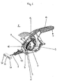
図1は、動力車両のハンドブレーキに使用することが可能な装置を示している。 FIG. 1 shows a device that can be used for handbrake of a powered vehicle.
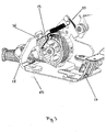
作動のために手動作動レバー13が存在し、このレバーには前部に当該ハンドブレーキを釈放するの可能にするアンロックノブ34が設けられている。該ハンドブレーキが制動位置にロックするように、図3に示すようにロック手段20が存在する。図4に示されるように、手動作動レバー13はグリップ62からなり、該グリップは絶縁材料から形成されると共に、保護シールド23に隣接している。グリップ62内には金属部分24が配され、該金属部は保護シールド23を超えて突出している。グリップ62とは反対側に位置する端部には、第1ベアリング点21が配設され、該ベアリング点上に上記手動作動レバーが回転可能に取り付けられている。この第1ベアリング点から数センチメートル離れて、第2ベアリング点22が該第1ベアリング点21の下に配置されると共に、図1ないし3に明確に見られるような張力エレメント3を取り付けるために設けられている。第2ベアリング点22は、第1ベアリング点21よりも幾らかグリップ62に近くに配置されている。図4に示されるように、グリップ62が矢印Aの方向に移動されると、第2ベアリング点22は矢印Bの方向に移動する。張力エレメント3上に固定的に配設されたものは弾性引張エレメント2であり、該エレメントは、グリップ62が矢印Aの方向に引っ張られた場合に、矢印Cの方向に移動され、かくしてハンドブレーキ効果を生じる。図3に示されるように、担持部分27及び28が基板26上の接続エレメント65に固定的に接続されている。当該装置1をシャーシに固定するための接続ブラケット29が部分27上に配設されている。図2に見られるように、張力エレメント3は、担持部分9上に配置された第3ベアリング点30において取り付けられている。担持部分9は、接続点37により前記金属部24に固定接続されている。このように、第2ベアリング点22は第1ベアリング点21に対して偏心的に配置され、その結果、グリップ62が引っ張られた場合に可撓性引張エレメント2に対して適切な力の伝達が生じる。即ち、上記第2ベアリング点は、矢印A方向のグリップの移動の最初の数センチメートルが、グリップ62即ち当該ハンドブレーキが制動位置にロックされる際の最後の数センチメートルよりも、一層大きく引張エレメント2を移動させように、配置されている。
There is a
図2にも見られるように、概ね半円形のガイドウェブ31及び32が、張力エレメント3上に引張エレメント2の左右に固定的に配設されている。更に、当該ハンドブレーキが引っ張られた場合、以下に説明するように、張力エレメント3が自身の回転軸33の廻りに回転しなくても張力エレメント3上に僅かに巻き上げられる。
As can also be seen in FIG. 2, generally
図1ないし3は、制動位置における装置1を示している。この位置においては、自身が回転可能であり、第2ベアリング点22において且つ第3ベアリング点30において自身が取り付けられている張力エレメント3は、コイル状スチールバネの形態の把持手段4により保持される。図3に明瞭に見られるように、上記スチールバネは実質的に張力エレメント3の周りに巻回されている。張力エレメント3は上記コイル状バネ、即ち把持手段4に対し、後述するように、該バネが開放されない限り実質的に非ポジティブに接続される。従って、該コイル状バネは自身のバネ力により張力エレメント3に非ポジティブに接続される。勿論、当該把持特性を改善するために、把持手段4と張力エレメント3との間に中間エレメント又は他の手段が存在するようにしてもよい。上記コイル状バネの2つの端部は外側に広がっており、その一方の端部が図3に明瞭に見られる。他方のバネ端部は担持部分9に固定的に接続されている。図2に明瞭に見られる当該バネの自由端36が下方に押されると、該バネは開く。何故なら、他方のバネ端部は強固に固定されているからである。このことは、上記コイル状バネ即ち把持手段4が開くか、又は該コイル状バネの直径が大きくなることを意味する。これは、当該自動再緊張の間に特別な役割を果たす。
1 to 3 show the
引張エレメント2の再緊張は、上記釈放位置においてのみ生じる。把持手段4は、該釈放位置においては張力エレメント3上を滑動することができるように構成されている。滑動は、バネ自由端36が係止エレメント5に突き当たることにより生じる。係止エレメント5に対するバネ自由端36の突き当たりは、手動作動レバー13が制動位置から釈放位置へ、即ち図1における矢印Dの方向に作動されることにより達成される。該釈放位置において、引張エレメント2は相対的に弛緩される。矢印Dの方向への、即ち下方への上記レバーの移動の間において、バネ自由端36は係止エレメント5に突き当たるまで矢印Eの方向、即ち上方に移動し、その結果、把持手段4を開放する動作が開始される。
Re-tensioning of the
張力エレメント3が最早把持手段4により囲まれなくなる故に回転可能になった場合に、該張力エレメントが前記引張エレメントを自動的に緊張させるように、図7、8及び10に見られるような螺旋状ヘリカルバネの形態の第2バネエレメント7が該張力エレメント3内に配設されている。
A spiral shape as seen in FIGS. 7, 8 and 10 so that when the tensioning element 3 can no longer be surrounded by the gripping means 4 and becomes rotatable, the tensioning element automatically tensions the tensioning element. A
該螺旋状ヘリカルバネは一端において担持部分9に固定的に接続される一方、他端は張力エレメント3に接続されている。張力エレメント3は、実際的には、バネ駆動型玩具におけるように、当該自動引き上げ機能を達成することができるようになる前に巻き上げられている。従って、本装置は上記引張エレメントのかなりの長さの変化を如何なる問題もなく補償することができる。引張エレメント2は曲げが可能な程度に可撓的である。この種の引張エレメント2は、“ボーデンケーブル”なる用語で既知である。
The spiral helium carbane is fixedly connected to the carrier portion 9 at one end, while the other end is connected to the tension element 3. The tension element 3 is actually wound up before the automatic pulling function can be achieved, as in a spring-driven toy. Thus, the device can compensate for considerable changes in the tension element without any problems. The
釈放位置においては、把持手段4は係止エレメント5により当該張力エレメントから釈放することができるので、即ち把持手段4は該張力エレメント3上を滑動することが可能であり、上記螺旋状バネ(即ち、第2バネエレメント7)のバネ効果を完全に利用することができるので、引張エレメント2は、経年変化による長さの変化に応じて、該張力エレメント3により巻き上げられる。
In the release position, the gripping means 4 can be released from the tension element by means of the
勿論、第2バネエレメント7のバネ力は、把持手段4と張力エレメント3との間の摩擦力を克服するように設定されねばならない。勿論、第2バネエレメント7のバネ力は車両のブレーキにおける制動作用をなすほど高くてはいけない。該第2バネエレメントは、引張エレメント2の自動的再緊張のみを生じさせることを意図するものである。
Of course, the spring force of the
図4及び図8は、把持手段4により釈放された場合に当該張力エレメント3が回転可能になる第2ベアリング点22を示している。
4 and 8 show a
図7に示すように、張力エレメント3は外側円柱表面に似た表面40を備えるリム状の第1部分38を有している。該第1部分38に加えて、張力エレメント3は、幾らか大きな直径を有すると共に引張エレメント2を案内するために設けられた第2部分39を有し、一方、前記第1部分38は把持手段4を受け入れるために設けられている。図8で分かるガイドウェブ31及び32は、上記第2部分39上に設けられている。該第2部分39内には中空室41が存在し、該中空室内に前記第2バネエレメント7が埋め込まれる。第1部分38内には、放射状に外方に向かう5つのリブ19が配設され、これらリブの間には、各々、空き空間42が存在する。
As shown in FIG. 7, the tension element 3 has a rim-shaped
図5に例示的に示される係止エレメント5は垂直部分42を有し、該垂直部分は、張力エレメント3の回転軸に平行に延びる水平部分43に隣接している。外側円柱表面に似た張力エレメント3の表面に対して接線方向に延びるバネ端部36は、上記水平部分43の領域に配置されている。結果として、手動作動レバー13が下降されると、バネ自由端36は係止エレメント5の水平部分43に突き当たる。この結果、把持手段(即ち、コイル状ヘリカルバネ)は、該バネが張力エレメント3に対して回転(又は滑動)することができるように押し広げられる。バネ自由端36が押し広げられることにより、該コイル状バネの直径は僅かに増加される。第2バネエレメント7を構成する螺旋状のヘリカルバネが、金属部分24と張力エレメント3との間に配置されているので、該第2バネエレメントのバネ力の結果として張力エレメント3は時計方向に(図2で見て)回転し、従って元来の引張エレメント2は自動的に巻き上げられる。ここで、可撓性引張エレメント2のうちの摩耗現象又は過応力により生じた部分のみが巻き上げられることに注意すべきである。
The locking
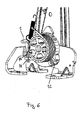
上記コイル状バネの製造誤差を補償するために、係止エレメント5は対応して調整可能なものとする。この目的のために、担持部分28上には長孔44が存在し、該長孔に対して係止エレメント5はリベット接続45により固定することができる。このように、係止エレメント5は垂直方向に調整可能に配設される。この調整は初期取り付けの間にのみ行われ、その際に係止エレメント5は担持部分28に対して固定的に接続される。図6は上記長孔44及び対応するリベット接続45を示している。
In order to compensate for the manufacturing error of the coiled spring, the locking
図2に示されるように、当該装置1は第3バネエレメント14を有し、該第3バネエレメントは装置1の担持部分9と第1バネエレメント6との間に、制動位置においては該第3バネエレメントが力増強効果を有して把持手段4の張力エレメント3に対する非ポジティブ接続を増強させる一方、釈放位置においては係止エレメント5が該第3バネエレメントの上記力効果を防止し、結果として該釈放位置において把持手段4が張力エレメント3に対して滑動することができるままとなるように配設されている。この目的のために、図2に示されるように、該第3バネエレメント14の一方のバネ端(符号46を有する)は担持部分9に接続され、他方のバネ端47は前記コイル状バネの自由バネ端36、即ち把持手段4に接続されている。この構成により、上記コイル状バネ、即ち把持手段4は張力エレメント3上に付加的に強固に押圧され、かくして、装置1が制動位置にある場合に把持手段4が如何なる場合においても張力エレメント3に対して滑らず、従って対応する標準規則が満たされ得ることを保証する。手動作動レバー13が釈放位置に移動されると、自由バネ端36は係止エレメント5に突き当たり、勿論その結果として、該第3バネエレメント14は、その効果を失う。即ち、係止エレメント5は該第3バネエレメントの力を防止する。
As shown in FIG. 2, the
図1に示すように、実際の車両ブレーキの間には可撓性引張エレメント2上に補償エレメント12が配設されている。該補償エレメント12は、引張エレメント2上において概ねT字状に構成され、可撓性引張エレメント2は中間に配置され、車両ブレーキに接続される図示せぬ更なる可撓性引張エレメントは反対側に配置される。引張エレメント2の適切な角度位置は、上記補償エレメント2と一緒に、2つの車両ブレーキが等しく良好に作動されることを保証する。この構成は、天秤に類似した構成に対応する。補償エレメント12はU字状断面として設計され、車両ブレーキの実際の引張エレメントが配置される点には符号50及び51が付されている。
As shown in FIG. 1, a
図2に示すように、装置1には可撓性ワイヤ状固定エレメントとして設計された取付固定エレメント16が設けられ、該取付固定エレメント16は一端において担持部分9に固着され、他端には鉤状突起17が配設されている。該エレメントは上記突起により、自身のバネ力に抗して、担持部分9に配設された窓状オリフィス18内に侵入することができる。該オリフィスの背後には、前記張力エレメント3のリブ19が配置されており、取付固定エレメント16は該リブにアンカ留めすることができる。これらリブ19は図5ないし7に明瞭に見ることができる。取付固定エレメント16の一端は担持部分9にネジ止めされ、従って当該装置1に係留的に接続されている。取付固定エレメント16は、取付の間において張力エレメント3を保持するように作用する。装置1が車両に取り付けられる前に、取付固定エレメント16はオリフィス18内に挿入され、結果としてリブ19が鉤状突起17に突き当たり、かくして、張力エレメント3が回転するのを防止する。取付固定エレメント16は実際にはリブ19によっても保持されるので、該取付固定エレメントは自身のバネ力が矢印G方向を指す場合でさえオリフィス18から飛び出すことはあり得ない。装置1の車両への取付が完了した場合、取付固定エレメント16は引張エレメント2が矢印Hの方向に引っ張られた場合に窓状オリフィス18から自動的に飛び出し、その結果、固定は自動的に解放される。これは、突起17がリブ19に対する保持を失うことにより達成される。
As shown in FIG. 2, the
更に、図6は引張エレメント2の固定点52を示し、該固定点52は張力エレメント3における前記第2部分39に設けられている。更に、図1及び図2は弾性封止エレメント53を示し、該封止エレメントは車両フレームにおける適切なオリフィスに配置することができる。
Further, FIG. 6 shows a
この例示的実施例において、第1バネエレメント6のバネ効果の下で張力エレメント3に対して非ポジティブに作用するような把持手段4を備える張力エレメント3は、本質的に回転対称な設計を有し、把持手段4はコイル状ヘリカルバネの形態に設計されている。例えば直線的配置のような他の構成も考えられるが、その場合には異なる把持手段4が張力エレメント3を非ポジティブにクランプすることになり、これは全く異なる幾何学形状を有するかも知れない。釈放位置において、把持手段4が、該把持手段が4が張力エレメント3上を滑動するか又は何らかの他の運動を行うことができるように、装置1上に配された係止エレメント5により当該張力エレメントから釈放することができるようにすることが重要である。係止エレメント5は緩む部品として製造する必要はなく、例えば打ち抜きノーズ等とすることもできる。自動的再緊張は、本質的に、釈放位置において、張力エレメント3が引張エレメント2を自動的に引っ張るように、該張力エレメント3が第2バネエレメント7の影響の下で移動可能となるように構成されると共に、該第2バネエレメント7のバネ力が設定されることにより生じる。ハンドブレーキの機能を維持するために、制動位置においては、把持手段4が張力エレメント3に非ポジティブに接続されることが勿論必要である。
In this exemplary embodiment, the tension element 3 with the gripping means 4 acting non-positively against the tension element 3 under the spring effect of the first spring element 6 has an essentially rotationally symmetric design. The gripping means 4 is designed in the form of a coiled helicabanet. Other configurations are also conceivable, for example a linear arrangement, in which case different gripping means 4 will clamp the tension element 3 non-positively, which may have a completely different geometry. In the released position, the gripping means 4 is moved by means of a
本発明は、この例示的実施例のみに限定されるものではなく、他の解決策も有することができるが、その場合、如何なる把持手段も自身の幾何学形状に無関係に如何なる所望の張力エレメントに対しても非ポジティブに作用するものとする。 The present invention is not limited to this exemplary embodiment, but can have other solutions, in which case any gripping means can be applied to any desired tension element regardless of its own geometry. It will also act non-positively.
1 装置
2 引張エレメント
3 張力エレメント
4 把持手段
5 係止エレメント
6 第1バネエレメント
7 第2バネエレメント
9 担持部分
12 補償エレメント
13 手動作動レバー
14 第3バネエレメント
16 取付固定エレメント
17 突起
18 オリフィス
19 リブ
DESCRIPTION OF
Claims (11)
(a)前記張力エレメント(3)には、コイル状第1バネ(4,6)の形態の少なくとも1つの把持手段(4,6)が設けられ、該第1バネは自身のバネ力によるバネ効果の下にあり、前記第1バネは前記制動位置において自身のバネ効果の下で前記張力エレメント(3)に対して非ポジティブに作用し、
(b)前記釈放位置において、前記把持手段(4,6)は前記張力エレメント(3)から、該把持手段(4,6)が前記張力エレメント(3)上を滑動するように釈放され、
(c)前記釈放位置において、前記引張エレメント(2)が自動的に再緊張されるように、前記張力エレメント(3)が第2バネエレメント(7)の影響の下で移動可能となるように構成されると共に、前記第2バネエレメント(7)のバネ力が設定されている、
ような装置において、
(d)前記装置(1)は第3バネエレメント(14)を有し、該第3バネエレメントが前記装置(1)の担持部分(9)と前記把持手段(4,6)との間に、前記制動位置において前記第3バネエレメント(14)が前記張力エレメント(3)に対する前記把持手段(4,6)の非ポジティブな接続を増強させるような力増強効果を有するように配設されている、
ことを特徴とする装置。Device (1) for actuating at least one vehicle brake, comprising a tensioning element (2), which can be moved to a braking position of the vehicle brake, in which the tensioning element (2 ) Can be tensioned by the tension element (3), the tension element can be moved to the release position, in which the tension element (2) is relaxed to the extent that the vehicle brake is released, In the device (1), the device is provided with a re-tensioning device for automatically re-tensioning the tensioning element in the release position,
(A) The tension element (3) is provided with at least one gripping means (4, 6) in the form of a coiled first spring (4, 6), the first spring being a spring by its own spring force. The first spring acts non-positively against the tension element (3) under its own spring effect in the braking position;
(B) In the release position, the gripping means (4, 6) is released from the tension element (3) so that the grip means (4, 6) slides on the tension element (3);
(C) In the release position, the tension element (3) is movable under the influence of the second spring element (7) so that the tension element (2) is automatically re-tensioned. And the spring force of the second spring element (7) is set.
In such a device,
(D) The device (1) has a third spring element (14), which is located between the carrying part (9) of the device (1) and the gripping means (4, 6). The third spring element (14) in the braking position is arranged to have a force-enhancing effect that enhances the non-positive connection of the gripping means (4, 6) to the tension element (3). Yes,
A device characterized by that.
Applications Claiming Priority (2)
| Application Number | Priority Date | Filing Date | Title |
|---|---|---|---|
| DE10151475A DE10151475B4 (en) | 2001-10-18 | 2001-10-18 | Device for actuating vehicle brakes |
| PCT/EP2002/011710 WO2003035441A1 (en) | 2001-10-18 | 2002-10-18 | Device for the actuation of vehicle brakes |
Publications (3)
| Publication Number | Publication Date |
|---|---|
| JP2005506243A JP2005506243A (en) | 2005-03-03 |
| JP2005506243A5 JP2005506243A5 (en) | 2006-01-05 |
| JP4282481B2 true JP4282481B2 (en) | 2009-06-24 |
Family
ID=7702939
Family Applications (1)
| Application Number | Title | Priority Date | Filing Date |
|---|---|---|---|
| JP2003537969A Expired - Fee Related JP4282481B2 (en) | 2001-10-18 | 2002-10-18 | Device for operating vehicle brakes |
Country Status (8)
| Country | Link |
|---|---|
| US (1) | US7637178B2 (en) |
| EP (1) | EP1453709B1 (en) |
| JP (1) | JP4282481B2 (en) |
| CN (1) | CN1269672C (en) |
| AT (1) | ATE312737T1 (en) |
| DE (2) | DE10151475B4 (en) |
| ES (1) | ES2254762T3 (en) |
| WO (1) | WO2003035441A1 (en) |
Families Citing this family (1)
| Publication number | Priority date | Publication date | Assignee | Title |
|---|---|---|---|---|
| CN104527623A (en) * | 2014-12-19 | 2015-04-22 | 荣成龙河车业有限公司 | Automobile hand brake with automatic braking function |
Family Cites Families (16)
| Publication number | Priority date | Publication date | Assignee | Title |
|---|---|---|---|---|
| US4515036A (en) * | 1983-04-25 | 1985-05-07 | Gulf & Western Manufacturing Company | Vehicle parking brake self-adjusting control mechanism |
| ES2004746A6 (en) | 1987-07-10 | 1989-02-01 | Pujol & Tarago | Handbrake compensator for motor vehicles |
| US4850242A (en) | 1988-07-19 | 1989-07-25 | Orscheln Co. | Soft-release cable operating means |
| US4841798A (en) * | 1988-08-30 | 1989-06-27 | Orscheln Co. | Foot-operated self-adjusting parking brake apparatus with controlled flyback |
| US5217094A (en) | 1991-08-09 | 1993-06-08 | Atwood Industries, Inc. | Self-adjusting, push-to-release parking brake control |
| US5309786A (en) * | 1993-03-08 | 1994-05-10 | Dura Mechanical Components, Inc. | Self-adjusting parking brake actuator |
| US5448928A (en) * | 1993-11-19 | 1995-09-12 | Dura Automotive Systems, Inc. | Variable ratio parking brake lever with self-adjust cable tensioning means |
| US5533420A (en) | 1994-05-20 | 1996-07-09 | Dura Automotive Holding, Inc. | Parking brake system including an internal clutch spring |
| ES2123394B1 (en) | 1995-08-31 | 2000-04-16 | Fico Cables Sa | SAFETY BRAKE MECHANISM. |
| US5907977A (en) * | 1996-04-30 | 1999-06-01 | Dura Automotive Systems, Inc. | Parking brake operating system having a take-up reel lockout and release mechanism, and method of assembling same |
| ES2138532B1 (en) * | 1997-05-26 | 2000-09-16 | Fico Cables Sa | SAFETY BRAKE MECHANISM FOR AUTOMOBILE VEHICLES. |
| DE19749551B4 (en) * | 1997-11-10 | 2005-05-19 | ED. SCHARWäCHTER GMBH | With a self-adjusting device equipped handbrake |
| US6363811B1 (en) * | 2000-03-07 | 2002-04-02 | Ficosa North American Corp. | Parking brake cable operating mechanism |
| KR100341294B1 (en) * | 2000-08-16 | 2002-06-22 | 이충곤 | Tension adjusting device for the cable of car parking brake |
| DE20109711U1 (en) | 2001-06-09 | 2001-08-30 | Edscha Ag | Parking brake for a motor vehicle |
| DE102004028737A1 (en) * | 2004-06-14 | 2006-01-05 | Fico Cables S.A. | Actuation system for a handbrake |
-
2001
- 2001-10-18 DE DE10151475A patent/DE10151475B4/en not_active Expired - Fee Related
-
2002
- 2002-10-18 AT AT02785248T patent/ATE312737T1/en not_active IP Right Cessation
- 2002-10-18 EP EP02785248A patent/EP1453709B1/en not_active Expired - Lifetime
- 2002-10-18 ES ES02785248T patent/ES2254762T3/en not_active Expired - Lifetime
- 2002-10-18 WO PCT/EP2002/011710 patent/WO2003035441A1/en active IP Right Grant
- 2002-10-18 CN CNB028242564A patent/CN1269672C/en not_active Expired - Fee Related
- 2002-10-18 US US10/493,073 patent/US7637178B2/en not_active Expired - Fee Related
- 2002-10-18 JP JP2003537969A patent/JP4282481B2/en not_active Expired - Fee Related
- 2002-10-18 DE DE60208075T patent/DE60208075T2/en not_active Expired - Lifetime
Also Published As
| Publication number | Publication date |
|---|---|
| CN1599679A (en) | 2005-03-23 |
| EP1453709B1 (en) | 2005-12-14 |
| JP2005506243A (en) | 2005-03-03 |
| CN1269672C (en) | 2006-08-16 |
| ATE312737T1 (en) | 2005-12-15 |
| ES2254762T3 (en) | 2006-06-16 |
| DE10151475B4 (en) | 2006-03-02 |
| DE60208075T2 (en) | 2006-08-24 |
| US20050183908A1 (en) | 2005-08-25 |
| DE10151475A1 (en) | 2003-05-08 |
| EP1453709A1 (en) | 2004-09-08 |
| US7637178B2 (en) | 2009-12-29 |
| DE60208075D1 (en) | 2006-01-19 |
| WO2003035441A1 (en) | 2003-05-01 |
Similar Documents
| Publication | Publication Date | Title |
|---|---|---|
| JPH0330788A (en) | Binding adjust instrument for ski boot | |
| US6973852B2 (en) | Parking brake comprising mechanism for adjusting brake cable tension | |
| US6382048B1 (en) | Self-adjustable cable tensioning device for parking brake of motor vehicle | |
| KR20000053304A (en) | Length adjustment device for seats, specially motor vehicle seats | |
| JP4282481B2 (en) | Device for operating vehicle brakes | |
| JP4741450B2 (en) | Indoor clothesline | |
| US6510757B1 (en) | Cable guide in a shift lever for bicycle gears | |
| TW202023936A (en) | Winch | |
| EP1669268A1 (en) | Cable tensioner for a vehicle hand brake | |
| US6843150B2 (en) | Parking brake assembly having quiet apply | |
| CA2324030C (en) | Parking brake assembly having quiet apply | |
| KR19990031139U (en) | Automatic tension adjusting device for parking brake cable | |
| JP2526442Y2 (en) | Parking brake operating device | |
| KR100348047B1 (en) | connection structure of parking brake lever | |
| KR20120059048A (en) | Parking Apparatus with Auto Tension Adjusting Function | |
| KR100279773B1 (en) | Parking cable fixing structure of foot parking brake | |
| KR200142759Y1 (en) | An automatic tension adjusting device for a parking brake | |
| JPH0218227Y2 (en) | ||
| KR0133231B1 (en) | Controller for parking brake | |
| JP2820309B2 (en) | Release handle device | |
| JP4291242B2 (en) | Parking brake device | |
| JPH0213330B2 (en) | ||
| JPH02249747A (en) | Parking brake device | |
| KR19980038082A (en) | Parking brake cable tension automatic adjuster | |
| JP2005506243A5 (en) |
Legal Events
| Date | Code | Title | Description |
|---|---|---|---|
| A521 | Request for written amendment filed |
Free format text: JAPANESE INTERMEDIATE CODE: A523 Effective date: 20050824 |
|
| A621 | Written request for application examination |
Free format text: JAPANESE INTERMEDIATE CODE: A621 Effective date: 20050824 |
|
| A131 | Notification of reasons for refusal |
Free format text: JAPANESE INTERMEDIATE CODE: A131 Effective date: 20080929 |
|
| A521 | Request for written amendment filed |
Free format text: JAPANESE INTERMEDIATE CODE: A523 Effective date: 20081215 |
|
| TRDD | Decision of grant or rejection written | ||
| A01 | Written decision to grant a patent or to grant a registration (utility model) |
Free format text: JAPANESE INTERMEDIATE CODE: A01 Effective date: 20090217 |
|
| A01 | Written decision to grant a patent or to grant a registration (utility model) |
Free format text: JAPANESE INTERMEDIATE CODE: A01 |
|
| A61 | First payment of annual fees (during grant procedure) |
Free format text: JAPANESE INTERMEDIATE CODE: A61 Effective date: 20090317 |
|
| R150 | Certificate of patent or registration of utility model |
Free format text: JAPANESE INTERMEDIATE CODE: R150 |
|
| FPAY | Renewal fee payment (event date is renewal date of database) |
Free format text: PAYMENT UNTIL: 20120327 Year of fee payment: 3 |
|
| FPAY | Renewal fee payment (event date is renewal date of database) |
Free format text: PAYMENT UNTIL: 20120327 Year of fee payment: 3 |
|
| S531 | Written request for registration of change of domicile |
Free format text: JAPANESE INTERMEDIATE CODE: R313531 |
|
| FPAY | Renewal fee payment (event date is renewal date of database) |
Free format text: PAYMENT UNTIL: 20120327 Year of fee payment: 3 |
|
| R360 | Written notification for declining of transfer of rights |
Free format text: JAPANESE INTERMEDIATE CODE: R360 |
|
| FPAY | Renewal fee payment (event date is renewal date of database) |
Free format text: PAYMENT UNTIL: 20120327 Year of fee payment: 3 |
|
| R370 | Written measure of declining of transfer procedure |
Free format text: JAPANESE INTERMEDIATE CODE: R370 |
|
| FPAY | Renewal fee payment (event date is renewal date of database) |
Free format text: PAYMENT UNTIL: 20130327 Year of fee payment: 4 |
|
| R250 | Receipt of annual fees |
Free format text: JAPANESE INTERMEDIATE CODE: R250 |
|
| R250 | Receipt of annual fees |
Free format text: JAPANESE INTERMEDIATE CODE: R250 |
|
| R250 | Receipt of annual fees |
Free format text: JAPANESE INTERMEDIATE CODE: R250 |
|
| R250 | Receipt of annual fees |
Free format text: JAPANESE INTERMEDIATE CODE: R250 |
|
| R250 | Receipt of annual fees |
Free format text: JAPANESE INTERMEDIATE CODE: R250 |
|
| LAPS | Cancellation because of no payment of annual fees |