CN1269672C - Device for the actuation of vehicle brakes - Google Patents
Device for the actuation of vehicle brakes Download PDFInfo
- Publication number
- CN1269672C CN1269672C CNB028242564A CN02824256A CN1269672C CN 1269672 C CN1269672 C CN 1269672C CN B028242564 A CNB028242564 A CN B028242564A CN 02824256 A CN02824256 A CN 02824256A CN 1269672 C CN1269672 C CN 1269672C
- Authority
- CN
- China
- Prior art keywords
- spring
- tension element
- tension
- traction
- fixing device
- Prior art date
- Legal status (The legal status is an assumption and is not a legal conclusion. Google has not performed a legal analysis and makes no representation as to the accuracy of the status listed.)
- Expired - Fee Related
Links
Images

Classifications
-
- B—PERFORMING OPERATIONS; TRANSPORTING
- B60—VEHICLES IN GENERAL
- B60T—VEHICLE BRAKE CONTROL SYSTEMS OR PARTS THEREOF; BRAKE CONTROL SYSTEMS OR PARTS THEREOF, IN GENERAL; ARRANGEMENT OF BRAKING ELEMENTS ON VEHICLES IN GENERAL; PORTABLE DEVICES FOR PREVENTING UNWANTED MOVEMENT OF VEHICLES; VEHICLE MODIFICATIONS TO FACILITATE COOLING OF BRAKES
- B60T7/00—Brake-action initiating means
- B60T7/02—Brake-action initiating means for personal initiation
- B60T7/08—Brake-action initiating means for personal initiation hand actuated
- B60T7/10—Disposition of hand control
- B60T7/108—Disposition of hand control with mechanisms to take up slack in the linkage to the brakes
-
- B—PERFORMING OPERATIONS; TRANSPORTING
- B60—VEHICLES IN GENERAL
- B60T—VEHICLE BRAKE CONTROL SYSTEMS OR PARTS THEREOF; BRAKE CONTROL SYSTEMS OR PARTS THEREOF, IN GENERAL; ARRANGEMENT OF BRAKING ELEMENTS ON VEHICLES IN GENERAL; PORTABLE DEVICES FOR PREVENTING UNWANTED MOVEMENT OF VEHICLES; VEHICLE MODIFICATIONS TO FACILITATE COOLING OF BRAKES
- B60T7/00—Brake-action initiating means
- B60T7/02—Brake-action initiating means for personal initiation
- B60T7/08—Brake-action initiating means for personal initiation hand actuated
- B60T7/10—Disposition of hand control
- B60T7/102—Disposition of hand control by means of a tilting lever
-
- Y—GENERAL TAGGING OF NEW TECHNOLOGICAL DEVELOPMENTS; GENERAL TAGGING OF CROSS-SECTIONAL TECHNOLOGIES SPANNING OVER SEVERAL SECTIONS OF THE IPC; TECHNICAL SUBJECTS COVERED BY FORMER USPC CROSS-REFERENCE ART COLLECTIONS [XRACs] AND DIGESTS
- Y10—TECHNICAL SUBJECTS COVERED BY FORMER USPC
- Y10T—TECHNICAL SUBJECTS COVERED BY FORMER US CLASSIFICATION
- Y10T74/00—Machine element or mechanism
- Y10T74/20—Control lever and linkage systems
- Y10T74/20396—Hand operated
- Y10T74/20402—Flexible transmitter [e.g., Bowden cable]
- Y10T74/20408—Constant tension sustaining
-
- Y—GENERAL TAGGING OF NEW TECHNOLOGICAL DEVELOPMENTS; GENERAL TAGGING OF CROSS-SECTIONAL TECHNOLOGIES SPANNING OVER SEVERAL SECTIONS OF THE IPC; TECHNICAL SUBJECTS COVERED BY FORMER USPC CROSS-REFERENCE ART COLLECTIONS [XRACs] AND DIGESTS
- Y10—TECHNICAL SUBJECTS COVERED BY FORMER USPC
- Y10T—TECHNICAL SUBJECTS COVERED BY FORMER US CLASSIFICATION
- Y10T74/00—Machine element or mechanism
- Y10T74/20—Control lever and linkage systems
- Y10T74/20576—Elements
- Y10T74/20582—Levers
- Y10T74/20612—Hand
-
- Y—GENERAL TAGGING OF NEW TECHNOLOGICAL DEVELOPMENTS; GENERAL TAGGING OF CROSS-SECTIONAL TECHNOLOGIES SPANNING OVER SEVERAL SECTIONS OF THE IPC; TECHNICAL SUBJECTS COVERED BY FORMER USPC CROSS-REFERENCE ART COLLECTIONS [XRACs] AND DIGESTS
- Y10—TECHNICAL SUBJECTS COVERED BY FORMER USPC
- Y10T—TECHNICAL SUBJECTS COVERED BY FORMER US CLASSIFICATION
- Y10T74/00—Machine element or mechanism
- Y10T74/20—Control lever and linkage systems
- Y10T74/20576—Elements
- Y10T74/20636—Detents
- Y10T74/20672—Lever engaging rack
- Y10T74/20684—Lever carried pawl
-
- Y—GENERAL TAGGING OF NEW TECHNOLOGICAL DEVELOPMENTS; GENERAL TAGGING OF CROSS-SECTIONAL TECHNOLOGIES SPANNING OVER SEVERAL SECTIONS OF THE IPC; TECHNICAL SUBJECTS COVERED BY FORMER USPC CROSS-REFERENCE ART COLLECTIONS [XRACs] AND DIGESTS
- Y10—TECHNICAL SUBJECTS COVERED BY FORMER USPC
- Y10T—TECHNICAL SUBJECTS COVERED BY FORMER US CLASSIFICATION
- Y10T74/00—Machine element or mechanism
- Y10T74/20—Control lever and linkage systems
- Y10T74/20576—Elements
- Y10T74/20636—Detents
- Y10T74/20672—Lever engaging rack
- Y10T74/2069—Handle release
Abstract
In a device ( 1 ) for the actuation of vehicle brakes, with a pull element ( 2 ) which can be brought into a lockable braking position in order to pull at least one braking means of the vehicle brakes, the pull element ( 2 ) being capable of being tensioned by a tension element ( 3 ) in this braking position, and which can be brought into a released position, in which the pull element ( 2 ) is relaxed to an extent such that the braking means is released, the device being provided with a retensioning device which, in the released position, automatically rentensions the pull element. The automatic resetting operation should take place as continuously as possible. This is achieved in that, that the tension element ( 3 ) is provided with at least one gripping means ( 4 ) which, in the braking position, acts non-positively on the tension element ( 3 ) under the spring effect of a first spring element ( 6 ), in that, that in the released position, the gripping means ( 4 ) can be released from the tension element ( 3 ) in such a way that the gripping means ( 4 ) slides over the tension element ( 3 ), and in that, that in the released position, the tension element ( 3 ) is arranged so as to be movable under the effect of a second spring element ( 7 ) in such a way and the spring force of the second spring element ( 7 ) is dimensioned in such a way that the pull element ( 2 ) is automatically retensioned.
Description
Technical field
The present invention relates to a kind of device that is used for the powered vehicle drg.
Background technology
This device is known by people, particularly relevant with the hand brake of power actuated vehicle device.Come the retro maneuver vehicle by the pulling hand brake, wherein control stalk is locked in the braking position.This device is provided with traction element usually, and Bowden cable (Bowden cable) particularly is so that be delivered to car brake with power from hand brake.Yet,, therefore will extend over time because the Bowden cable is subjected to constant stress.The result of elongation must readjust hand brake after certain period of time.Known means are to utilize screw thread and nut to carry out this tension.Yet the shortcoming of this solution is: readjust on the one hand and must manual carry out, on the other hand, the position of control stalk is different with the position before the adjustment.Therefore usually can feel to be unfamiliar with and have side effects the new location of control stalk.
In order to address this problem known a kind of device, the wherein retighten automatically of traction element quilt.Utilize functionally similar indention generation automatic compensation with ratchet.Yet because in each case, the variation of length must surpass predetermined teeth size at least, and any length variations that therefore is not traction element all can be conditioned.If this adjustment again is continuous as far as possible, must make selected tooth as much as possible little so thus.If tooth is too little, then has to disconnect the danger that the shape face connects (positiveconnection), and lose the effect of hand brake.Another shortcoming be the adjustment period between cause offending noise.At last, also a shortcoming is that tooth has undesirable burr.
U.S. Patent application US-5,907,977A shows a kind of brake parking lever that has the hawser clamping system, comprises spring clutch mechanism, is used for automatically eliminating the lax of stopping brake hawser.Spring clutch only engages wheel shaft by the spring force of itself.
Summary of the invention
Therefore, the purpose of this invention is to provide a kind of device that is used for the powered vehicle drg, wherein, produce the operation of resetting automatically as far as possible continuously, and do not have above-mentioned shortcoming.
Can realize above-mentioned purpose by a kind of device that is used to drive at least one car brake, described device has traction element, described traction element can be introduced into the braking position of described car brake, wherein said traction element can be by the tension element tensioning in this braking position, and, described traction element can be introduced into the releasing position, wherein traction element is released to such degree: promptly described car brake is released, and wherein said device is provided with tightening device again, described tightening device again is tensioning traction element again automatically in the releasing position, wherein, tension element is provided with at least one fixing device that adopts convoluted form of springs, described convoluted spring is under the elastic force effect of self spring force, and in braking position, described convoluted spring element joins on the tension element in the mode to the tension element application of force under himself elastic force effect; In the releasing position, described fixing device is discharged from tension element by this way: promptly fixing device slips over tension element; With in the releasing position, tension element is set to and can moves in the automatically slack-free again mode of traction element under the effect of second spring element, and the size of the spring force of second spring element is set in the automatically slack-free again mode of traction element; It is characterized in that: described device has the 3rd spring element, described the 3rd spring element is disposed between the load bearing component and fixing device of described device by this way: promptly in braking position, the 3rd spring element has the power booster action and engages with the application of force between the tension element so that strengthen fixing device.
Because tension element is provided with at least one fixing device, described at least one fixing device joins on the tension element tension element is executed power-assisted mode (non-positively) under the spring force effect of first spring element, therefore opposite with forward connection by tooth scheme or similar scheme, can realize continuous adjusting, and described adjusting operation is not perceiveed even.That is to say both do not have " card clatter " noise also without any other beat noise or vibrations.
The acquisition of auto-tensioning is: in the releasing position, can in the mode that fixing device slips over tension element fixing device be discharged from tension element by the element that stops that being arranged on the device.Correspondingly, the acquisition of the actual tight function of re-opening is: in the releasing position, tension element is arranged to and can be under the effect of second spring element be moved by slack-free again mode automatically with traction element, and the spring force of second spring element is determined size with traction element by slack-free again mode automatically, simultaneously, in braking position, fixing device joins tension element in the mode to the tension element application of force.
Particularly advantageous is that if tension element is set to and can rotates under the effect of second spring element, the result can obtain the embodiment of highly compact so.The S. A. of tension element is set to depart from the centre of gration of manual actuation lever, produces particularly advantageous power transmission thereby can and drive between the traction element of drg at the manual actuation lever of hand brake.
When fixing device is the convoluted spring that is under the elastic reaction of self elastic force, obtained a kind of scheme of special saving cost.
Useful especially is, tension element has first cylindrical portions may, convoluted spring is arranged regularly around described first cylindrical portions may, convoluted spring is fixedly joined to load bearing component (carrying part) at a spring end place, and in another spring end place formation free spring end portion, described free spring end portion and outer cylinder surface is tangent and can be stopped element drives by this way: promptly the increasing diameter of convoluted spring is added to the cylindrical portions may d/d degree from the convoluted spring that makes, this be because, as its result, on the one hand, high convenience scheme with regard to assembling is provided, on the other hand, provide more cost-effective well-known components.
In addition, useful especially is, stop element being arranged to adjustable, the result, the production tolerance of fixing device can be compensated, perhaps, described device can be conditioned so that reset automatically.
In addition, useful is, described traction element is provided with shim element, thereby the difference between a plurality of drg moves and can be compensated.
Described device has the 3rd spring element, described the 3rd spring element is disposed between the load bearing component and first spring element of described device by this way: promptly in braking position, the 3rd spring element has the power booster action and engages with the application of force between the tension element so that strengthen fixing device, and in the releasing position, describedly stop the power effect that element is offset the 3rd spring element, result's fixing device in the releasing position can continue to slide with respect to tension element; Thus, the function of the hand brake in braking position all is held in each case, particularly can realize whole standard values.
Being used to produce suitable power with the particularly advantageous scheme of straining traction element is, second spring element is spiral coil spring, thereby described spring element can be readily incorporated in the described device especially.
Described device is installed in the vehicle is easy to, as long as arrange assembling fixing units, described assembling fixing units can be introduced in the installation site, and described assembling fixing units remains on tension element in the installation site.
Obtain in the following manner to make an easier simple and favourable especially scheme is installed: described assembling fixing units is designed to elasticity wire retaining element, the one end is fixedly connected to load bearing component, its other end has hook-shaped outstanding, described hook-shaped outstanding can utilize it outstanding overcomes its elastic force and penetrates in the window opening that is arranged on the load bearing component, the rib of tension element is disposed in the back in hole, and described assembling fixing units can be fixed on the described rib.
Description of drawings
Illustrate in greater detail the present invention with reference to exemplary embodiments, in described embodiment, further characteristics of the present invention and advantage will be described.In the drawings:
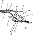
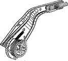
Fig. 1 shows the transparent view of described device;
Fig. 2 shows according to graphic amplification details shown in Figure 1;
Fig. 3 shows the transparent view of different angles, and load bearing component is not shown;
Fig. 4 illustrates the lateral plan of described device;
Fig. 5 shows the transparent view of the device that only partly is mounted;
Fig. 6 shows the view of corresponding diagram 5 from different visual angles;
Fig. 7 shows the transparent view of each parts of device, and each parts of described device are by separated from each other;
Fig. 8 shows from different visual angles according to transparent view Fig. 7, that each parts are mounted;
Fig. 9 shows the view according to Fig. 8 from different visual angles;
Figure 10 shows the lateral plan of the device that partly is mounted.
The specific embodiment
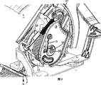
Fig. 1 shows the device in the hand brake that can be used on power actuated vehicle.
In order to drive, there is a front portion to have the manual actuation lever 13 of unlocking knob 34, unlocking knob 34 makes and might discharge hand brake.Because have blocking device 20, hand brake is locked on the braking position, as shown in Figure 3.As shown in Figure 4, manual actuation lever 13 comprises handle 62, and it is made by insulating material, and adjacent with protective cover 23.Metal parts 24 is arranged in the handle 62, and described metal parts 24 reaches beyond the protective cover 23.At an end relative with handle 62 first supporting-point 21 is set, manual actuation lever is installed in rotation on described first supporting-point 21.Apart from described first supporting-point, more than 21 centimeters, second supporting-point 22 be arranged on described first supporting-point 21 below, and be used to install the tension element 3 that is clearly shown that by Fig. 1 to 3.Second supporting-point, 22 to the first supporting-point 21 will be slightly near handle 62 some.Therefore, as shown in Figure 4, when handle 62 when the arrow A direction moves, second supporting-point 22 moves along the arrow B direction.Elastic traction element 2 is arranged on the tension element 3 regularly, when handle 62 when the arrow A direction is pulled, described elastic traction element 2 moves along the arrow C direction, thereby excites the hand brake effect.As shown in Figure 3, load bearing component 27 and 28 is fixedly joined on the attaching parts 65 on the substrate 25.Be used for the device 1 connection support 29 that is fastened to the chassis is arranged on load bearing component 27.As shown in Figure 2, tension element 3 is installed in the 3rd supporting-point 30 places, and described the 3rd supporting-point 30 is arranged on the load bearing component 9.Load bearing component 9 is fixedly joined on the metal parts 24 by point of connection 37.Therefore, second supporting-point 22 deviates from first supporting-point 21 and arranges, during tow handle 62, produces suitable power transmission with box lunch on flexible drawing element 2.That is to say that the arrangement of second supporting-point is: when handle 62 or hand brake are locked in the braking position, big along first centimetre of degree of the clamping campaign of arrow A direction than the mobile traction element 2 of last centimetre.
As shown in Figure 2, be substantially on the tension element 3 that semi-round guiding web (guide web) 31 and 32 is arranged on traction element 2 left and right sides regularly.And when pulling during hand brake, even when tension element 3 during not around himself S. A. 33 rotation, traction element 2 also is rolls-up onto on the tension element 3 slightly, will be described in detail below.
Fig. 1 to 3 shows the device 1 in the braking position.In this position, rotatable tension element 3 own itself is installed in second supporting-point 22 and the 3rd supporting-point 30 places, and described tension element 3 is kept by the fixing device 4 of coiling steel spring form.Can be clear that as Fig. 3 in fact steel spring is wound on the tension element 3.In fact tension element 3 is engaged in the mode to tension element 3 application of forces by the spring of coiling shape or clamping element 4, unless described spring launches, the back will be described.Therefore, coiling shape spring joins on the tension element 3 in the mode to tension element 3 application of forces under the effect of self spring force.Certainly, in order to improve the clamping attribute, between fixing device 4 and tension element 3, can be provided with middleware or other device.Launch at the two ends of rolled spring, and a spring end is fixedly connected on the load bearing component 9, and another spring end can be clear that in Fig. 3.Can be clear that from Fig. 2 because a spring terminal is firmly fixed, therefore when to lower compression free spring end 36, spring launches.This just means: rolled spring or fixing device 4 launch or the diameter of rolled spring becomes big.It is special that this plays a part during re-opening tightly automatically.
Again the tensioning of traction element 2 only takes place in d/d position.On the releasing position, fixing device 4 is provided so that and can slips over tension element 3.The generation of sliding is to stop element 5 because free spring end 36 supports to bump.By being driven into releasing position (promptly along Fig. 1 arrow D direction) from braking position, manual actuation lever 13 can realize free spring end 36 and the collision that stops element 5.In the releasing position, traction element 2 is more loose relatively.In the direction of arrow D between moving period, during just moving downward, free spring end 36 moves along the arrow E direction at control stalk, and upward movement is just run into up to it and to be stopped element 5, and the result starts the expansion operation of fixing device 4.
Therefore can find out that from Fig. 7,8 and 10 second spring element 7 of spiral fashion coil spring form is set at the inside of tension element 3, center on and become when turning because of no longer clamped 4 when tension element 3 that it can strain traction element automatically,
The helical spring end of spiral fashion is fixedly connected to load bearing component 9, and the other end is connected on the tension element 3.Tension element 3 is in fact rolled-up before realizing spurring function automatically, as in the spring driven toy.Therefore, described device can compensate sizable variation of traction element length without a doubt.Traction element 2 is because flexible thereby be flexible.Such traction element 2 with " Bowden cable " by known.
Because in the releasing position, fixing device 4 can discharge from tension element by stopping element 5, perhaps fixing device 4 can slip over tension element 3, and, the elastic reaction of the spiral spring or second spring element 7 can be scattered fully, therefore according to the variation that causes on length owing to catabiosis, traction element 2 is rolled-up by tension element 3.
Certainly, the size of the spring force of second element 7 must be set like this: promptly it can overcome the friction force between fixing device 4 and the tension element 3.Certainly, the spring force of second spring element 7 should be so not high, so that realize brake action at the car brake place.Second spring element is just tight in order to produce re-opening automatically of traction element 2.
Fig. 4 and Fig. 8 show second supporting-point 22, and be rotatable when clamped device 4 discharges at this some place tension element 3.
As shown in Figure 7, tension element 3 has the first 38 of wheel rim shape, the surface 10 similar outer cylinder surfaces of first 38.Except first 38, tension element 3 also has second portion 39, and second portion 39 has big slightly diameter, and is provided with and is used for guiding traction element 2, and first 38 is provided with and is used for receiving fixing device 4.Guiding web 31 and 32 shown in Figure 8 is arranged on the second portion 39.In the inside of second portion 39 are hollow chamber 41, embed second spring element 7 in hollow chamber 41.Be provided with five ribs 19 in first 38, described rib radially outward is provided with, and has clearance envelope 19 ' between any two at these ribs.
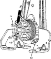
In Fig. 5, has vertical component 42 with the element 5 that stops shown in the example, the horizontal component 43 that described vertical component extends in abutting connection with being parallel to the rotation axis of tension element 3, free spring end portion 36 is arranged in the zone of horizontal component 43, the tension element 3 of described free spring end portion 36 and similar outer cylinder surface surperficial tangent and extending.Therefore, when reducing manual actuation lever 13, free spring end 36 is in abutting connection with the horizontal component 43 that stops element 5.Consequently, fixing device 4 or rolled coil spring launch by this way: promptly the latter is rotatable or can slide with respect to tension element 3.Along with free spring end portion 36 launches, the diameter of rolled spring increases slightly.Because constituting the helix coil spring of second spring element 7 is arranged between metal parts 24 and the tension element 3, therefore because the effect of the spring force of second spring element, tension element 3 anticlockwise directions rotations (referring to Fig. 2), thus representative type traction element 2 is rolled automatically.Should be noted in the discussion above that and have only that part of rolled-up of the flexible drawing element 2 that occurs owing to wear phenomenon or unfair stress.
In order to compensate the production tolerance of coiling shape spring, stop correspondingly scalable of element 5.For this purpose, on load bearing component 28, have elongated hole 44, stop element 5 and can connect 45 by rivet and be fixed to elongated hole 44.Stopping element 5 therefore is set to vertically adjustable.This adjusting only takes place when initial the installation, wherein stops element 5 and is fixedly joined to load bearing component 28.Fig. 6 shows elongated hole 4 and is connected 45 with corresponding rivet.
As shown in Figure 2, device 1 has the 3rd spring element 14, described the 3rd spring element 14 is arranged between the load bearing component 9 and first spring element 6 of device 1, its set-up mode is: at braking position, the 3rd spring element has the power booster action so that increasing fixing device 4 engages with the application of force between the tension element 3, and in the releasing position, stops the power effect that element 5 offsets the 3rd spring element, as a result, still can slide at releasing position fixing device 4 with respect to tension element 3.For this reason, as shown in Figure 2, a spring end of the 3rd spring element 14 is connected to load bearing component 9, and this spring end has Reference numeral 46, and another spring end 47 is connected to the free spring end portion 36 or the fixing device 4 of rolled spring.By this layout, rolled coil spring or fixing device 4 are pressed on the tension element 3 again securely, thereby can guarantee that fixing device 4 can slide with respect to tension element 3 in no instance when device 1 is in braking position, regulate thereby can satisfy corresponding standard.When manual actuation lever 13 moved to the releasing position, free spring end 36 was in abutting connection with stopping element 5, and certainly, the result is that the 3rd spring element 14 loses its effect.That is, stop the effect that element 5 has offseted the 3rd spring element.
As shown in Figure 1, shim element 12 is arranged between the existing car brake on the flexible drawing element 2.Shim element 12 approximately is arranged on the traction element 2 T-shapedly, and flexible drawing element 2 is arranged in the middle part, and the traction element (not shown) that is connected to car brake in addition is arranged in the end of opposite side.Traction element 2 has guaranteed that with the suitable angle position of shim element 12 two car brakes are similarly well driven.This layout is corresponding to the structure that is similar to balance.Shim element 12 is designed to the U-shaped profile, and the point that the existing traction element of car brake is set up is given Reference numeral 50 and 51.
As shown in Figure 2, device 1 is provided with assembling fixing units 15, described assembling fixing units 15 is designed to the retaining element of elasticity wire, and the one end is fixedly joined to load bearing component 9, being provided with hook-shaped outstanding 17, described hook-shaped outstanding 17 at its other end can overcome its spring force and utilizes its outstanding being penetrated in the window-like orifice 18 that is arranged on the load bearing component 9.18 back is provided with the rib 19 of tension element 3 in the hole, and assembling fixing units 15 can be fixed on this rib 19.In Fig. 5 to Fig. 7, can be clear that rib 19.One end of assembling fixing units 15 by screw fixed to load bearing component 9, but therefore the place of capture is connected on the device 1.Fixing device for installing 15 is used for keeping during installation tension element 3.Before device 1 was installed in the vehicle, assembling fixing units 15 was inserted in the hole 18, and rib 19 is given prominence to 17 adjacency with hook-shaped as a result, thereby prevented tension element 3 rotations.Because assembling fixing units 15 in fact also keeps by rib 19, so it can not expose from hole 18, even can not expose along the elastic force point of arrow G direction.When device 1 installation in vehicle, assembling fixing units 15 is jumped out window opening 18 automatically at traction element 2 when arrow H direction draw, therefore fixes automatically to be discharged.This is no longer kept realizing by rib 19 owing to outstanding 17.
In addition, Fig. 6 shows the attachment point 52 that is used for traction element 2, and described attachment point 52 is set on the second portion 39 in the tension element 3.And Fig. 1 and 2 shows elastic sealing elements 53, and described elastic sealing elements 53 can be disposed in the suitable opening part in the vehicle frame.
In this exemplary embodiments, tension element 3 is provided with fixing device 4, described fixing device 4 is bonded on the tension element 3 in the mode to tension element 3 application of forces under the spring force effect of first spring element 6, described tension element 3 has rotatable basically symmetric design, and fixing device 4 is designed to the helical spring form of rolled.Also it is contemplated that other layout, for example linear arrangement still, clamps tension element 3 to 4 pairs of tension element 3 application of forces of wherein different clamping elements, and described tension element 3 can have diverse geometric configuration.Importantly, in the releasing position, fixing device 4 can be discharged from tension element by this way by the element 5 that stops that being arranged in the device 1: promptly fixing device 4 can slide, and perhaps can carry out other the motion of crossing tension element 3.Stopping element 5 does not need to make loose components, but for example can be to go out nose or analogue yet.Automatically heavy slack-free essence takes place to be, in the releasing position, tension element 3 is set to and can moves in the mode of automatically drawing on traction element 2 with tension element 3 under the effect of second spring element 7, and the size of the spring force of second spring element 7 is set in the mode that tension element 3 automatically draws on traction element 2.In order to keep the function of drg, certainly, be necessary in braking position, to make fixing device 4 to join on the tension element 3 in mode to tension element 3 application of forces.
The present invention is not limited to these exemplary embodiments, but also comprises other scheme, wherein, any fixing device, no matter what its geometric configuration is, all is bonded on any desired tension element tension element is executed power-assisted mode.
Claims (11)
1. a device (1), be used to drive at least one car brake, described device has traction element (2), described traction element (2) can be introduced into the braking position of described car brake, wherein said traction element (2) can be by tension element (3) tensioning in this braking position, and, described traction element (2) can be introduced into the releasing position, wherein traction element (2) is released to such degree: promptly described car brake is released, and wherein said device is provided with tightening device again, described tightening device again is tensioning traction element again automatically in the releasing position, wherein
A) tension element (3) is provided with the fixing device (4) that at least one adopts convoluted spring (4) form, described convoluted spring (4) is under the elastic force effect of self spring force, and in braking position, described convoluted spring element (4) joins on the tension element (3) in the mode to tension element (3) application of force under himself elastic force effect;
B) in the releasing position, described fixing device (4) is discharged from tension element (3) by this way: promptly fixing device (4) slips over tension element (3); With
C) in the releasing position, tension element (3) is set to and can moves in the automatically slack-free again mode of traction element (2) under the effect of second spring element (7), and the size of the spring force of second spring element (7) is set in the automatically slack-free again mode of traction element (2); It is characterized in that:
D) described device (1) has the 3rd spring element (14), described the 3rd spring element (14) is disposed between the load bearing component (9) and fixing device (4) of described device (1) by this way: promptly in braking position, the 3rd spring element (14) has the power booster action and engages with the application of force between the tension element (3) so that strengthen fixing device (4).
2. device according to claim 1, it is characterized in that, described tension element (3) is set to and can rotates under the effect of second spring element (7), and in the releasing position, the release of fixing device (4) drives by the element (5) that stops that being arranged on the device (1).
3. device according to claim 2 is characterized in that, the rotation axis of described tension element (3) is set to depart from the centre of gration of manual actuation lever (13).
4. device according to claim 3, it is characterized in that, described tension element (3) comprises first cylindrical portions may (10), convoluted spring (4) is fixedly arranged around described first cylindrical portions may (10), convoluted spring is fixedly joined to load bearing component (9) at an one spring end place, and form free spring end portion (36) at another spring end, described free spring end portion (36) and outer cylinder surface are tangent, and can be stopped element (5) and drives by this way: the increasing diameter of promptly convoluted spring (4) is added to and makes first cylindrical portions may by the degree of convoluted spring (4) release.
5. device according to claim 2 is characterized in that, the described element (5) that stops to be arranged to scalable.
6. device according to claim 1 is characterized in that, shim element (12) is arranged on the traction element (2).
7. device according to claim 1 is characterized in that, in the power effect that stops element (5) counteracting the 3rd spring element (14) described in the releasing position, the result is in the releasing position, and fixing device (4) can continue to slide with respect to tension element (3).
8. device according to claim 1 is characterized in that, described second spring element (7) is the spiral fashion coil spring.
9. device according to claim 1 is characterized in that, assembling fixing units (15) is set, and described assembling fixing units (15) can be introduced in the installation site, and described assembling fixing units (15) remains on tension element (3) in the installation site.
10. device according to claim 9 is characterized in that, described assembling fixing units (15) is connected to device (1) by screwing.
11. device according to claim 10, it is characterized in that, described assembling fixing units (15) is designed to elasticity wire retaining element, the one end is fixedly connected to load bearing component (9), its other end has hook-shaped outstanding (17), described hook-shaped outstanding (17) can utilize its outstanding (17) to overcome its spring force and penetrate in the window opening (18) that is arranged on the load bearing component (9), wherein the rib (19) of tension element (3) is disposed in the back of hole (18), and described assembling fixing units (15) can be fixed on the described rib.
Applications Claiming Priority (2)
| Application Number | Priority Date | Filing Date | Title |
|---|---|---|---|
| DE10151475A DE10151475B4 (en) | 2001-10-18 | 2001-10-18 | Device for actuating vehicle brakes |
| DE10151475.1 | 2001-10-18 |
Publications (2)
| Publication Number | Publication Date |
|---|---|
| CN1599679A CN1599679A (en) | 2005-03-23 |
| CN1269672C true CN1269672C (en) | 2006-08-16 |
Family
ID=7702939
Family Applications (1)
| Application Number | Title | Priority Date | Filing Date |
|---|---|---|---|
| CNB028242564A Expired - Fee Related CN1269672C (en) | 2001-10-18 | 2002-10-18 | Device for the actuation of vehicle brakes |
Country Status (8)
| Country | Link |
|---|---|
| US (1) | US7637178B2 (en) |
| EP (1) | EP1453709B1 (en) |
| JP (1) | JP4282481B2 (en) |
| CN (1) | CN1269672C (en) |
| AT (1) | ATE312737T1 (en) |
| DE (2) | DE10151475B4 (en) |
| ES (1) | ES2254762T3 (en) |
| WO (1) | WO2003035441A1 (en) |
Families Citing this family (1)
| Publication number | Priority date | Publication date | Assignee | Title |
|---|---|---|---|---|
| CN104527623A (en) * | 2014-12-19 | 2015-04-22 | 荣成龙河车业有限公司 | Automobile hand brake with automatic braking function |
Family Cites Families (16)
| Publication number | Priority date | Publication date | Assignee | Title |
|---|---|---|---|---|
| US4515036A (en) * | 1983-04-25 | 1985-05-07 | Gulf & Western Manufacturing Company | Vehicle parking brake self-adjusting control mechanism |
| ES2004746A6 (en) | 1987-07-10 | 1989-02-01 | Pujol & Tarago | Handbrake compensator for motor vehicles |
| US4850242A (en) | 1988-07-19 | 1989-07-25 | Orscheln Co. | Soft-release cable operating means |
| US4841798A (en) * | 1988-08-30 | 1989-06-27 | Orscheln Co. | Foot-operated self-adjusting parking brake apparatus with controlled flyback |
| US5217094A (en) | 1991-08-09 | 1993-06-08 | Atwood Industries, Inc. | Self-adjusting, push-to-release parking brake control |
| US5309786A (en) * | 1993-03-08 | 1994-05-10 | Dura Mechanical Components, Inc. | Self-adjusting parking brake actuator |
| US5448928A (en) * | 1993-11-19 | 1995-09-12 | Dura Automotive Systems, Inc. | Variable ratio parking brake lever with self-adjust cable tensioning means |
| US5533420A (en) | 1994-05-20 | 1996-07-09 | Dura Automotive Holding, Inc. | Parking brake system including an internal clutch spring |
| ES2123394B1 (en) | 1995-08-31 | 2000-04-16 | Fico Cables Sa | SAFETY BRAKE MECHANISM. |
| US5907977A (en) | 1996-04-30 | 1999-06-01 | Dura Automotive Systems, Inc. | Parking brake operating system having a take-up reel lockout and release mechanism, and method of assembling same |
| ES2138532B1 (en) | 1997-05-26 | 2000-09-16 | Fico Cables Sa | SAFETY BRAKE MECHANISM FOR AUTOMOBILE VEHICLES. |
| DE19749551B4 (en) * | 1997-11-10 | 2005-05-19 | ED. SCHARWäCHTER GMBH | With a self-adjusting device equipped handbrake |
| US6363811B1 (en) * | 2000-03-07 | 2002-04-02 | Ficosa North American Corp. | Parking brake cable operating mechanism |
| KR100341294B1 (en) * | 2000-08-16 | 2002-06-22 | 이충곤 | Tension adjusting device for the cable of car parking brake |
| DE20109711U1 (en) | 2001-06-09 | 2001-08-30 | Edscha Ag | Parking brake for a motor vehicle |
| DE102004028737A1 (en) * | 2004-06-14 | 2006-01-05 | Fico Cables S.A. | Actuation system for a handbrake |
-
2001
- 2001-10-18 DE DE10151475A patent/DE10151475B4/en not_active Expired - Fee Related
-
2002
- 2002-10-18 ES ES02785248T patent/ES2254762T3/en not_active Expired - Lifetime
- 2002-10-18 US US10/493,073 patent/US7637178B2/en not_active Expired - Fee Related
- 2002-10-18 AT AT02785248T patent/ATE312737T1/en not_active IP Right Cessation
- 2002-10-18 DE DE60208075T patent/DE60208075T2/en not_active Expired - Lifetime
- 2002-10-18 WO PCT/EP2002/011710 patent/WO2003035441A1/en active IP Right Grant
- 2002-10-18 EP EP02785248A patent/EP1453709B1/en not_active Expired - Lifetime
- 2002-10-18 CN CNB028242564A patent/CN1269672C/en not_active Expired - Fee Related
- 2002-10-18 JP JP2003537969A patent/JP4282481B2/en not_active Expired - Fee Related
Also Published As
| Publication number | Publication date |
|---|---|
| ES2254762T3 (en) | 2006-06-16 |
| EP1453709B1 (en) | 2005-12-14 |
| JP2005506243A (en) | 2005-03-03 |
| DE10151475B4 (en) | 2006-03-02 |
| EP1453709A1 (en) | 2004-09-08 |
| DE60208075T2 (en) | 2006-08-24 |
| DE10151475A1 (en) | 2003-05-08 |
| WO2003035441A1 (en) | 2003-05-01 |
| JP4282481B2 (en) | 2009-06-24 |
| CN1599679A (en) | 2005-03-23 |
| US20050183908A1 (en) | 2005-08-25 |
| ATE312737T1 (en) | 2005-12-15 |
| DE60208075D1 (en) | 2006-01-19 |
| US7637178B2 (en) | 2009-12-29 |
Similar Documents
| Publication | Publication Date | Title |
|---|---|---|
| RU2503572C1 (en) | Air deflector height mount and air deflector with such mount | |
| CN1620380A (en) | Electrically driven parking brake actuation assembly | |
| CN1912416A (en) | Rapid take up and vibration proof adjuster mechanism | |
| US7798572B2 (en) | Manual adjustment of a back support on a vehicle seat | |
| CN1269672C (en) | Device for the actuation of vehicle brakes | |
| US8479890B2 (en) | Actuating assembly | |
| US4889007A (en) | Adjusting device for a vehicle parking brake | |
| CN2677696Y (en) | Vehicle rear-wheel disk brake | |
| US7383927B2 (en) | Operating mechanism for a parking brake | |
| CN211543309U (en) | Vehicle seat slide rail structure and vehicle seat | |
| CN1038739C (en) | Lever-type hoist and traction apparatus | |
| JP2022548443A (en) | Steering column anti-rotation device | |
| US20070175291A1 (en) | Anti-loosening device for parking brake | |
| US20140000406A1 (en) | Manual parking brake with an over-center helper spring | |
| CN200971296Y (en) | Brake device of power hoister | |
| CN219214971U (en) | Brake auxiliary device | |
| KR102548635B1 (en) | Noise reduction device for vehicle parking brake | |
| KR101241929B1 (en) | Electronic parking brake | |
| CN209757073U (en) | Parking stay wire automatic adjusting mechanism, parking brake operating device and vehicle | |
| CN101412425B (en) | Brake apparatus | |
| CN2180542Y (en) | Automobile brake | |
| CN1976837A (en) | Electric brake actuating assembly | |
| KR0160258B1 (en) | Stopper for parking brake cable auto adjusting device | |
| KR100192307B1 (en) | An automatic tension-adjustment apparatus for a brake cable | |
| KR100387794B1 (en) | A device to fasten cable of parking brake |
Legal Events
| Date | Code | Title | Description |
|---|---|---|---|
| C06 | Publication | ||
| PB01 | Publication | ||
| C10 | Entry into substantive examination | ||
| SE01 | Entry into force of request for substantive examination | ||
| C14 | Grant of patent or utility model | ||
| GR01 | Patent grant | ||
| C19 | Lapse of patent right due to non-payment of the annual fee | ||
| CF01 | Termination of patent right due to non-payment of annual fee |