EP1453709B1 - Device for the actuation of vehicle brakes - Google Patents
Device for the actuation of vehicle brakes Download PDFInfo
- Publication number
- EP1453709B1 EP1453709B1 EP02785248A EP02785248A EP1453709B1 EP 1453709 B1 EP1453709 B1 EP 1453709B1 EP 02785248 A EP02785248 A EP 02785248A EP 02785248 A EP02785248 A EP 02785248A EP 1453709 B1 EP1453709 B1 EP 1453709B1
- Authority
- EP
- European Patent Office
- Prior art keywords
- spring
- tension element
- tension
- gripping means
- pull
- Prior art date
- Legal status (The legal status is an assumption and is not a legal conclusion. Google has not performed a legal analysis and makes no representation as to the accuracy of the status listed.)
- Expired - Lifetime
Links
Images


Classifications
-
- B—PERFORMING OPERATIONS; TRANSPORTING
- B60—VEHICLES IN GENERAL
- B60T—VEHICLE BRAKE CONTROL SYSTEMS OR PARTS THEREOF; BRAKE CONTROL SYSTEMS OR PARTS THEREOF, IN GENERAL; ARRANGEMENT OF BRAKING ELEMENTS ON VEHICLES IN GENERAL; PORTABLE DEVICES FOR PREVENTING UNWANTED MOVEMENT OF VEHICLES; VEHICLE MODIFICATIONS TO FACILITATE COOLING OF BRAKES
- B60T7/00—Brake-action initiating means
- B60T7/02—Brake-action initiating means for personal initiation
- B60T7/08—Brake-action initiating means for personal initiation hand actuated
- B60T7/10—Disposition of hand control
- B60T7/108—Disposition of hand control with mechanisms to take up slack in the linkage to the brakes
-
- B—PERFORMING OPERATIONS; TRANSPORTING
- B60—VEHICLES IN GENERAL
- B60T—VEHICLE BRAKE CONTROL SYSTEMS OR PARTS THEREOF; BRAKE CONTROL SYSTEMS OR PARTS THEREOF, IN GENERAL; ARRANGEMENT OF BRAKING ELEMENTS ON VEHICLES IN GENERAL; PORTABLE DEVICES FOR PREVENTING UNWANTED MOVEMENT OF VEHICLES; VEHICLE MODIFICATIONS TO FACILITATE COOLING OF BRAKES
- B60T7/00—Brake-action initiating means
- B60T7/02—Brake-action initiating means for personal initiation
- B60T7/08—Brake-action initiating means for personal initiation hand actuated
- B60T7/10—Disposition of hand control
- B60T7/102—Disposition of hand control by means of a tilting lever
-
- Y—GENERAL TAGGING OF NEW TECHNOLOGICAL DEVELOPMENTS; GENERAL TAGGING OF CROSS-SECTIONAL TECHNOLOGIES SPANNING OVER SEVERAL SECTIONS OF THE IPC; TECHNICAL SUBJECTS COVERED BY FORMER USPC CROSS-REFERENCE ART COLLECTIONS [XRACs] AND DIGESTS
- Y10—TECHNICAL SUBJECTS COVERED BY FORMER USPC
- Y10T—TECHNICAL SUBJECTS COVERED BY FORMER US CLASSIFICATION
- Y10T74/00—Machine element or mechanism
- Y10T74/20—Control lever and linkage systems
- Y10T74/20396—Hand operated
- Y10T74/20402—Flexible transmitter [e.g., Bowden cable]
- Y10T74/20408—Constant tension sustaining
-
- Y—GENERAL TAGGING OF NEW TECHNOLOGICAL DEVELOPMENTS; GENERAL TAGGING OF CROSS-SECTIONAL TECHNOLOGIES SPANNING OVER SEVERAL SECTIONS OF THE IPC; TECHNICAL SUBJECTS COVERED BY FORMER USPC CROSS-REFERENCE ART COLLECTIONS [XRACs] AND DIGESTS
- Y10—TECHNICAL SUBJECTS COVERED BY FORMER USPC
- Y10T—TECHNICAL SUBJECTS COVERED BY FORMER US CLASSIFICATION
- Y10T74/00—Machine element or mechanism
- Y10T74/20—Control lever and linkage systems
- Y10T74/20576—Elements
- Y10T74/20582—Levers
- Y10T74/20612—Hand
-
- Y—GENERAL TAGGING OF NEW TECHNOLOGICAL DEVELOPMENTS; GENERAL TAGGING OF CROSS-SECTIONAL TECHNOLOGIES SPANNING OVER SEVERAL SECTIONS OF THE IPC; TECHNICAL SUBJECTS COVERED BY FORMER USPC CROSS-REFERENCE ART COLLECTIONS [XRACs] AND DIGESTS
- Y10—TECHNICAL SUBJECTS COVERED BY FORMER USPC
- Y10T—TECHNICAL SUBJECTS COVERED BY FORMER US CLASSIFICATION
- Y10T74/00—Machine element or mechanism
- Y10T74/20—Control lever and linkage systems
- Y10T74/20576—Elements
- Y10T74/20636—Detents
- Y10T74/20672—Lever engaging rack
- Y10T74/20684—Lever carried pawl
-
- Y—GENERAL TAGGING OF NEW TECHNOLOGICAL DEVELOPMENTS; GENERAL TAGGING OF CROSS-SECTIONAL TECHNOLOGIES SPANNING OVER SEVERAL SECTIONS OF THE IPC; TECHNICAL SUBJECTS COVERED BY FORMER USPC CROSS-REFERENCE ART COLLECTIONS [XRACs] AND DIGESTS
- Y10—TECHNICAL SUBJECTS COVERED BY FORMER USPC
- Y10T—TECHNICAL SUBJECTS COVERED BY FORMER US CLASSIFICATION
- Y10T74/00—Machine element or mechanism
- Y10T74/20—Control lever and linkage systems
- Y10T74/20576—Elements
- Y10T74/20636—Detents
- Y10T74/20672—Lever engaging rack
- Y10T74/2069—Handle release
Definitions
- the invention relates to a device according to the precharacterizing clause of claim 1.
- Devices of this type are known, in particular, in connection with handbrakes of motor vehicles.
- the motor vehicle is braked by a handbrake being pulled, wherein the lever locks in the braking position.
- Devices of this type are normally provided with a pull element, in particular a Bowden cable, in order to transmit the force from the handbrake to the vehicle brakes. Since the Bowden cable is subjected to constant stress, however, it stretches in the course of time. The result of this stretching is that the handbrake has to be reset after a specific period of time. It is known to carry out this tightening by means of a thread and a nut.
- the disadvantage of this solution is that, on the one hand, resetting must take place manually and, on the other hand, the lever position is different from before the adjustment. This new lever position is often felt to be unfamiliar and therefore has an adverse effect.
- the US-A-5,907,977 shows a parking brake lever with a cable tensioning system comprising a spring clutch mechanism for automatically removing slack from a parking brake cable.
- the spring clutch engages a hub only by means of its own spring force.
- the object of the present invention is, therefore, to provide a device according to the precharacterizing clause of claim 1, in which the automatic resetting operation takes place as continuously as possible, without the disadvantages mentioned above.
- the tension element is provided with at least one gripping means acting non-positively on the tension element under the spring effect of a first spring element, continuous adjustment is achieved, in contrast to a positive connection by means of a tooth solution or the like, and the adjustment operation is not even noticed. That is to say, there are neither clicking noises nor any other knocking noises or vibrations.
- automatic tensioning is achieved in that, in the released position, the gripping means can be released from the tension element by means of a stop element arranged on the device, in such a way that the gripping means slides over the tension element.
- the actual retensioning function is accordingly achieved in that, in the released position, the tension element is arranged so as to be movable under the effect of a second spring element in such a way and the spring force of the second spring element is dimensioned in such a way that the tension element is automatically retensioned, whilst, in the braking position, the gripping means is connected non-positively to the tension element.
- the tension element is arranged so as to be rotatable under the effect of the second spring element, with the result that a highly compact embodiment is achieved. So that a particularly favorable force transmission can take place between a manual actuation lever of the handbrake and the pull element which actuates the brakes, the axis of rotation of the tension element is arranged eccentrically to the center of rotation of the manual actuation lever.
- the gripping means is a coil-like spring which is under a spring effect due to its own spring force.
- the tension element has a cylindrical portion, around which the coil-like spring is arranged fixedly, and that the coil-like spring is fixedly connected at one spring end to a carrying part, whilst at its other spring end the spring forms an actuating portion which is arranged tangentially to the outer cylindrical surface and which can be actuated by the stop element in such a way that the diameter of the coil-like spring is increased to an extent such that the cylindrical portion is released from the coil-like spring, because, as a result of this, on the one hand, a solution highly convenient in terms of assembly has been afforded and, on the other hand, known parts which are relatively cost-effective are provided.
- stop element is arranged adjustably, with the result that manufacturing tolerances in the gripping means can be compensated or with the result that the device can be adjusted for the automatic resetting.
- the pull element is provided with a compensating element, because different movements of a plurality of brakes can thereby be compensated.
- the device has the third spring element which is arranged between a carrier part of the device and the first spring element in such a way that, in the braking position, the third spring element has a force-intensifying effect in order to increase the non-positive connection of the gripping means to the tension element, whilst, in the released position, the stop element counteracts the force effect of the third spring element, with the result that, in the released position, the gripping means continues to be capable of sliding with respect to the tension element.
- a particularly favorable solution for generating the appropriate force for tightening the pull element is for the second spring element to be a helical spring in spiral form, so that the spring element is capable of being integrated particularly easily into the device.
- the mounting of the device in a vehicle is made substantially easier if a mounting securing element is arranged, which can be brought into a mounting position, the mounting securing element retaining the tension element in the mounting position.
- the mounting securing element being designed as a resilient wire-like securing element which is fixedly connected at one end to a carrier part and at its other end has a hook-like projection which is capable of penetrating with its projection into a window-like orifice counter to its spring force, a rib of the tension element being arranged behind the orifice, and the mounting securing element being capable of being anchored to said rib.
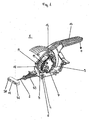
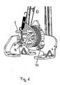
- Figure 1 shows a device which can be used in a handbrake of a motor vehicle.
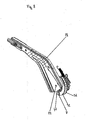
- the manual actuation lever 13 which is provided at the front with an unlocking knob 34 making it possible to release the handbrake. So that the handbrake locks in the braking position, locking means 20 are present, as shown in Figure 3.
- the manual actuation lever 13 consists of a grip 62 which is made of insulating material and which adjoins a protecting shield 23. Arranged in the grip 62 is a metal part 24 which projects beyond the protecting shield 23. At the end located opposite the grip 22 is arranged a first bearing point 21, on which the manual actuation lever is mounted rotatably.
- a second bearing point 22 is arranged below this first bearing point 21 and is provided for mounting a tension element 3 which can be seen clearly in Figures 1 to 3.
- the second bearing point 22 is arranged somewhat nearer the grip 62 than the first bearing point 21.
- the tension element 3 is arranged fixedly on the tension element 3 which, when the grip 62 is pulled in the direction of the arrow A, is moved in the direction of the arrow C, thus actuates the handbraking effect.
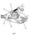
- Carrying parts 27 and 28 are connected fixedly to connection elements 65 on the baseplate 25, as shown in Figure 3.
- a connecting bracket 29 for fastening the device 1 to the chassis is arranged on the part 27.
- the tension element 3 is mounted at a third bearing point 30 arranged on a carrying part 9.
- the carrying part 9 is connected fixedly to the metal part 24 by means of a connection point 37.
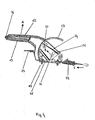
- the second bearing point 22 is therefore arranged eccentrically to the first bearing point 21, so that suitable force transmission takes place when the grip 62 is pulled on the flexible pull element 2. That is to say, the second bearing point is arranged in such a way that the first centimeters of the gripping movement in the direction of the arrow A move the pull element 2 to a greater extent than the last centimeters when the grip 62 or the handbrake is locked in the braking position.
- approximately semicircular guide webs 31 and 32 are arranged fixedly on the tension element 3 on the left and right of the pull element 2. Moreover, when the handbrake is pulled, the pull element 2 is rolled up slightly on the tension element 3, even when the tension element 3 does not rotate about its own axis of rotation 33, as will be explained below.
- Figures 1 to 3 show the device 1 in the braking position.
- the tension element 3, rotatable per se, which is mounted per se at the second bearing point 22 and at the third bearing point 30, is retained by a gripping means 4 in the form of a steel spring in coil form.
- the steel spring is wound virtually around the tension element 3, as can be seen clearly in Figure 3.
- the tension element 3 is connected virtually non-positively to the coil-like spring or the gripping means 4, unless said spring is opened, as described later.
- the coil-like spring is therefore connected non-positively by its own spring force to the tension element 3.
- intermediate elements or other means may be present between the gripping means 4 and the tension element 3.
- the two ends of the coil-like spring are spread out, and one end can be seen clearly in Figure 3.
- the other spring end is connected fixedly to the carrying part 9.
- the free spring end 36 which can be seen clearly in Figure 2
- the spring opens, because the other spring end is firmly fixed. This means that the coil-like spring or the gripping means 4 opens or the diameter of the coil-like spring becomes larger. This plays a particular role during in the automatic retensioning.
- the retensioning of the pull element 2 takes place in the released position only.
- the gripping means 4 is arranged so as to be capable of sliding over the tension element 3. Sliding takes place in that the free spring end 36 butts against a stop element 5.
- the butting of the free spring end 36 against the stop element 5 is achieved by the manual actuation lever 13 being actuated from the braking position into the released position, that is to say in the direction of the arrow D in Figure 1.
- the pull element 2 is relatively relaxed.
- the spioral-like helical spring is fixedly connected at its one end to the carrying part 9, whilst the other end is connected to the tension element 3.
- the tension element 3 is, in practice, wound up before it can achieve the automatic pull-up function, as in a spring-driven toy. The device can therefore compensate considerable changes in length of the pull element without any problems.
- the pull element 2 is flexible in as much as it is bendable. Pull elements 2 of this type are known by the term "Bowden cable".
- the gripping means 4 can be released from the tension element by the stop element 5 or the gripping means 4 is capable of sliding over the tension element 3 and the spring effect of the spiral-like spring or the second spring element 7 can be fully deployed, the pull element 2 is rolled up, according to its change in length due to the aging phenomenon, by means of the tension element 3.
- the spring force of the second element 7 must, of course, be dimensioned in such a way that it overcomes the frictional force between the gripping means 4 and the tension element 3.
- the spring force of the second spring element 7 should not be so high that it achieves a braking action at the vehicle brakes.
- the second spring element is intended to bring about only the automatic retensioning of the pull element 2.
- Figures 4 and 8 show the second bearing point 22, at which the tension element 3 is rotatable when it is released by the gripping means 4.
- the tension element 3 has a rim-like first portion 38 with a surface 49 resembling an outer cylindrical surface.
- the tension element 3 has, in addition to the first portion 38, a second portion 39 which has a somewhat larger diameter and is provided for guiding the pull element 2, whilst the first portion 38 is provided for receiving the gripping means 4.
- the guide webs 31 and 32 which are identified in Figure 8, are arranged on the second portion 39.
- Inside the second portion 39 there is a hollow chamber 41, in which the second spring element 7 is embedded.
- the first portion 38 are arranged five ribs which are directed radially outwards and between which there are in each case free spaces 42.
- the stop element 5 which is shown by way of example in Figure 5, has a vertical portion 42 which adjoins a horizontal portion 43 running parallel to the axis of rotation of the tension element 3, the spring end 36, which runs tangentially to the surface of the tension element 3 resembling an outer cylindrical surface, being arranged in the region of the horizontal portion 43. Consequently, when the manual actuation lever 13 is lowered, the free spring end 36 butts onto the horizontal portion 43 of the stop element 5. The result of this is that the gripping means 4 or the coil-like helical spring is spread open in such a way that the latter can rotate or can slide with respect to the tension element 3. By the free spring end 36 being spread open, the diameter of the coil-like spring is increased slightly.
- the stop element 5 is correspondingly adjustable.
- the carrying part 28 there is on the carrying part 28 a elongated hole 44, to which the stop element 5 can be fastened by means of a rivet connection 45.
- the stop element 5 is thus arranged so as to be vertically adjustable. This adjustment takes place only during initial mounting, wherein the stop element 5 is being connected fixedly to the carrying part 28.
- Figure 6 shown the elongated hole 4 and the corresponding rivet connection 45.
- the device 1 has a third spring element 14 which is arranged between the carrier part 9 of the device 1 and the first spring element 6 in such a way that, in the braking position, the third spring element has a force-intensifying effect in order to increase the non-positive connection of the gripping means 4 to the tension element 3, whilst, in the released position, the stop element 5 counteracts the force effect of the third spring element, with the result that, in the released position, the gripping means 4 continues to be capable of sliding with respect to the tension element 3.
- one spring end of the third spring element 14 is connected to the carrier part 9, this spring end having the reference number 46, whilst the other spring end 47 is connected to the free spring end 36 of the coil-like spring or to the gripping means 4.
- the coil-like helical spring or the gripping means 4 is additionally pressed firmly on the tension element 3, thus ensuring that, when the device 1 is in the braking position, the gripping means 4 does not in any case slide with respect to the tension element 3, so that the corresponding standard regulations can be met.
- the manual actuation lever 13 is moved into the released position, the free spring end 36 butts onto the stop element 5, of course, with the result that the third spring element 14 loses its effect. That is to say, the stop element 5 counteracts the force of the third spring element.
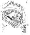
- a compensating element 12 is arranged on the flexible pull element 2 between the actual vehicle brakes.
- the compensating element 12 is arranged, approximately T-shaped, on the pull element 2, the flexible pull element 2 being arranged in the middle and further flexible pull elements, not illustrated, which are connected to the vehicle brakes, being arranged at the ends on the opposite side.
- An appropriate angular position of the pull element 2 together with the compensating element 12 ensures that the two vehicle brakes are actuated equally well. This arrangement corresponds to the arrangement similar to a balance.
- the compensating element 12 is designed as a U profile, the points at which the actual pull elements of the vehicle brake are arranged being given the reference numbers 50 and 51.
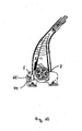
- the device 1 is provided with a mounting securing element 15 which is designed as a resilient wire-like securing element, the mounting securing element 15 being fixedly connected at one end to the carrier part 9, and there being arranged at the other end a hook-like projection 17 which is capable of penetrating with its projection, counter to its spring force, into a window-like orifice 18 arranged on the carrier part 9. Behind the orifice 18 are arranged the ribs 19 of the tension element 3 to which the mounting securing element 15 can be anchored. The ribs 19 can be seen clearly in Figures 5 to 7. One end of the mounting securing element 15 is screwed to the carrier part 9 and is therefore connected captively to the device 1.
- the mounting securing element 15 serves for holding the tension element 3 during mounting.
- the mounting securing element 16 is inserted in the orifice 18, with the result that a rib 19 butts on the hook-like projection 17, thus preventing the tension element 3 from rotating. Since the mounting securing element 16 is also retained, in practice, by the rib 19, it cannot emerge from the orifice 18, even though its spring force points in the direction of the arrow G.
- the mounting securing element 16 automatically jumps out of the window-like orifice 18 when the pull element 2 is pulled in the direction of the arrow H, with the result that the securing is automatically released. This was achieved by the projection 17 losing its hold on the rib 19.
- Figure 6 shows a fastening point 52 for the pull element 2, the fastening point 52 being arranged on the second portion 39 in the tension element 3.
- Figures 1 and 2 show an elastic sealing element 53 which can be arranged at an appropriate orifice in the vehicle frame.
- the tension element 3, which is provided with the gripping means 4 acting non-positively on the tension element 3 under the spring effect of the first spring element 6, has an essentially rotationally symmetrical design, and the gripping means 4 is designed in the form of a coil-like helical spring.
- Other arrangements for example a linear arrangement, may be envisaged, however, in which a different gripping element 4 non-positively clamps the tension element 3, which may have a completely different geometric shape. It is important that, in the released position, the gripping means 4 be capable of being released from the tension element by the stop element 5 arranged on the device 1 in such a way that the gripping means 4 is capable of sliding, or of any other movement over the tension element 3.
- the stop element 5 does not need to be produced as a loose part, but may, for example, also be a punched-out nose or the like. Automatic retensioning takes place essentially in that, that in the released position, the tension element 3 is arranged so as to be movable under the effect of the second spring element 7 in such a way and the spring force of the second spring element 7 is dimensioned in such a way that the tension element 3 automatically pulls on the pull element 2. In order to hold the functioning of the handbrake, it is, of course, necessary, in the braking position, for the gripping element 4 to be connected non-positively to the tension element 3.
- the invention is not only restricted to this exemplary embodiment, but also comprises other solutions, in which any gripping means, irrespective of its geometric shape, acts non-positively on any desired tension element.
Landscapes
- Engineering & Computer Science (AREA)
- Transportation (AREA)
- Mechanical Engineering (AREA)
- Braking Arrangements (AREA)
- Springs (AREA)
- Braking Elements And Transmission Devices (AREA)
- Regulating Braking Force (AREA)
- Clamps And Clips (AREA)
- Braking Systems And Boosters (AREA)
Abstract
Description
- Figure 1
- shows a perspective illustration of the device;
- Figure 2
- shows an enlarged detail of the illustration according to Figure 1;
- Figure 3
- shows a perspective illustration from a different viewing angle, a carrying part not being illustrated;
- Figure 4
- shows a side view of the device;
- Figure 5
- shows a perspective illustration of the device which is only partially mounted;
- Figure 6
- shows a corresponding view of Figure 5, but from a different viewing angle;
- Figure 7
- shows a perspective illustration of various parts of the device which are pulled apart from one another;
- Figure 8
- shows a perspective illustration according to Figure 7, but with mounted parts and from a different viewing angle;
- Figure 9
- shows an illustration according to Figure 8, but from a different viewing angle, and
- Figure 10
- shows a side view of the partially mounted device.
Claims (11)
- Device (1) for the actuation of at least one vehicle brake, with a pull element (2) which can be brought into a braking position of said vehicle brake, the pull element (2) being capable of being tensioned by a tension element (3) in this braking position, and which can be brought into a released position, in which the pull element (2) is relaxed to an extent such that said vehicle brake is released, the device being provided with a retensioning device which, in the released position, automatically retensions the pull element, whereina) the tension element (3) is provided with at least one gripping means (4, 6) in the form of a coil-like first spring (4, 6) which is under a spring effect due to its own spring force and which in the braking position, acts non-positively on the tension element (3) under its spring effect;b) in the released position, the gripping means (4, 6) is released from the tension element (3) in such a way that the gripping means (4, 6) slides over the tension element (3); andc) in the released position, the tension element (3) is arranged so as to be movable under the effect of a second spring element (7) in such a way and the spring force of the second spring element (7) is dimensioned in such a way that the pull element (2) is automatically retensioned; characterized in thatd) the device (1) has a third spring element (14) which is arranged between a carrier part (9) of the device (1) and the gripping means (4, 6) in such a way that, in the braking position, the third spring element (14) has a force-intensifying effect in order to increase the non-positive connection of the gripping means (4, 6) to the tension element (14).
- Device according to claim 1, characterized in that the tension element (3) is arranged so as to be rotatable under the effect of the second spring element (7), and, in the released position, the release of the gripping means (4) is brought about by means of a stop element (5) arranged on the device (1).
- Device according to claim 2, characterized in that the axis of rotation of the tension element (3) is arranged eccentrically to the center of rotation of a manual actuation lever (13).
- Device according to claim 3, characterized in that the tension element (3) has a cylindrical portion (10), around which the coil-like spring is fixedly arranged, and in that the coil-like spring is fixedly connected at its one spring end to a carrying part (9), whilst at its other spring end the spring forms an actuating portion (11) which is arranged tangentially to the outer cylindrical surface and which can be actuated by the stop element (5) in such a way that the diameter of the coil-like spring is increased to an extent such that the cylindrical portion is released by the coil-like spring.
- Device according to one of the preceding claims 2 to 4, characterized in that the stop element (5) is arranged adjustably.
- Device according to one of the preceding claims, characterized in that a compensating element (12) is arranged on the pull element (2).
- Device according to one of the preceding claims 2 to 6, characterized in that, the stop element (5) in the released position counteracts the force effect of the third spring element (14), with the result that, in the released position, the gripping means (4) continues to be capable of sliding with respect to the tension element (3).
- Device according to one of the preceding claims, characterized in that the second spring element (7) is a helical spring in worm form.
- Device according to one of the preceding claims, characterized in that a mounting securing element (15) is arranged, which can be brought into a mounting position, the mounting securing element (15) retaining the tension element (3) in the mounting position.
- Device according to claim 9, characterized in that the mounting securing element (15) is connected captively to the device (1).
- Device according to claim 10, characterized in that the mounting securing element (15) is designed as a resilient wire-like securing element which is fixedly connected at one end to a carrier part (9) and at its other end has a hook-like projection (17) which is capable of penetrating with its projection (17) into a window-like orifice (18) counter to its spring force, a rib (19) of the tension element (3) being arranged behind the orifice (18), and the mounting securing element (15) being capable of being anchored to said rib (19).
Applications Claiming Priority (3)
| Application Number | Priority Date | Filing Date | Title |
|---|---|---|---|
| DE10151475 | 2001-10-18 | ||
| DE10151475A DE10151475B4 (en) | 2001-10-18 | 2001-10-18 | Device for actuating vehicle brakes |
| PCT/EP2002/011710 WO2003035441A1 (en) | 2001-10-18 | 2002-10-18 | Device for the actuation of vehicle brakes |
Publications (2)
| Publication Number | Publication Date |
|---|---|
| EP1453709A1 EP1453709A1 (en) | 2004-09-08 |
| EP1453709B1 true EP1453709B1 (en) | 2005-12-14 |
Family
ID=7702939
Family Applications (1)
| Application Number | Title | Priority Date | Filing Date |
|---|---|---|---|
| EP02785248A Expired - Lifetime EP1453709B1 (en) | 2001-10-18 | 2002-10-18 | Device for the actuation of vehicle brakes |
Country Status (8)
| Country | Link |
|---|---|
| US (1) | US7637178B2 (en) |
| EP (1) | EP1453709B1 (en) |
| JP (1) | JP4282481B2 (en) |
| CN (1) | CN1269672C (en) |
| AT (1) | ATE312737T1 (en) |
| DE (2) | DE10151475B4 (en) |
| ES (1) | ES2254762T3 (en) |
| WO (1) | WO2003035441A1 (en) |
Families Citing this family (1)
| Publication number | Priority date | Publication date | Assignee | Title |
|---|---|---|---|---|
| CN104527623A (en) * | 2014-12-19 | 2015-04-22 | 荣成龙河车业有限公司 | Automobile hand brake with automatic braking function |
Family Cites Families (16)
| Publication number | Priority date | Publication date | Assignee | Title |
|---|---|---|---|---|
| US4515036A (en) * | 1983-04-25 | 1985-05-07 | Gulf & Western Manufacturing Company | Vehicle parking brake self-adjusting control mechanism |
| ES2004746A6 (en) | 1987-07-10 | 1989-02-01 | Pujol & Tarago | Handbrake compensator for motor vehicles |
| US4850242A (en) | 1988-07-19 | 1989-07-25 | Orscheln Co. | Soft-release cable operating means |
| US4841798A (en) * | 1988-08-30 | 1989-06-27 | Orscheln Co. | Foot-operated self-adjusting parking brake apparatus with controlled flyback |
| US5217094A (en) | 1991-08-09 | 1993-06-08 | Atwood Industries, Inc. | Self-adjusting, push-to-release parking brake control |
| US5309786A (en) * | 1993-03-08 | 1994-05-10 | Dura Mechanical Components, Inc. | Self-adjusting parking brake actuator |
| US5448928A (en) * | 1993-11-19 | 1995-09-12 | Dura Automotive Systems, Inc. | Variable ratio parking brake lever with self-adjust cable tensioning means |
| US5533420A (en) | 1994-05-20 | 1996-07-09 | Dura Automotive Holding, Inc. | Parking brake system including an internal clutch spring |
| ES2123394B1 (en) | 1995-08-31 | 2000-04-16 | Fico Cables Sa | SAFETY BRAKE MECHANISM. |
| US5907977A (en) * | 1996-04-30 | 1999-06-01 | Dura Automotive Systems, Inc. | Parking brake operating system having a take-up reel lockout and release mechanism, and method of assembling same |
| ES2138532B1 (en) | 1997-05-26 | 2000-09-16 | Fico Cables Sa | SAFETY BRAKE MECHANISM FOR AUTOMOBILE VEHICLES. |
| DE19749551B4 (en) * | 1997-11-10 | 2005-05-19 | ED. SCHARWäCHTER GMBH | With a self-adjusting device equipped handbrake |
| US6363811B1 (en) * | 2000-03-07 | 2002-04-02 | Ficosa North American Corp. | Parking brake cable operating mechanism |
| KR100341294B1 (en) * | 2000-08-16 | 2002-06-22 | 이충곤 | Tension adjusting device for the cable of car parking brake |
| DE20109711U1 (en) | 2001-06-09 | 2001-08-30 | Edscha AG, 42855 Remscheid | Parking brake for a motor vehicle |
| DE102004028737A1 (en) * | 2004-06-14 | 2006-01-05 | Fico Cables S.A. | Actuation system for a handbrake |
-
2001
- 2001-10-18 DE DE10151475A patent/DE10151475B4/en not_active Expired - Fee Related
-
2002
- 2002-10-18 DE DE60208075T patent/DE60208075T2/en not_active Expired - Lifetime
- 2002-10-18 WO PCT/EP2002/011710 patent/WO2003035441A1/en active IP Right Grant
- 2002-10-18 ES ES02785248T patent/ES2254762T3/en not_active Expired - Lifetime
- 2002-10-18 JP JP2003537969A patent/JP4282481B2/en not_active Expired - Fee Related
- 2002-10-18 AT AT02785248T patent/ATE312737T1/en not_active IP Right Cessation
- 2002-10-18 EP EP02785248A patent/EP1453709B1/en not_active Expired - Lifetime
- 2002-10-18 US US10/493,073 patent/US7637178B2/en not_active Expired - Fee Related
- 2002-10-18 CN CNB028242564A patent/CN1269672C/en not_active Expired - Fee Related
Also Published As
| Publication number | Publication date |
|---|---|
| DE60208075T2 (en) | 2006-08-24 |
| EP1453709A1 (en) | 2004-09-08 |
| ATE312737T1 (en) | 2005-12-15 |
| US20050183908A1 (en) | 2005-08-25 |
| CN1269672C (en) | 2006-08-16 |
| DE60208075D1 (en) | 2006-01-19 |
| US7637178B2 (en) | 2009-12-29 |
| JP2005506243A (en) | 2005-03-03 |
| CN1599679A (en) | 2005-03-23 |
| DE10151475A1 (en) | 2003-05-08 |
| JP4282481B2 (en) | 2009-06-24 |
| ES2254762T3 (en) | 2006-06-16 |
| DE10151475B4 (en) | 2006-03-02 |
| WO2003035441A1 (en) | 2003-05-01 |
Similar Documents
| Publication | Publication Date | Title |
|---|---|---|
| JP3987978B2 (en) | Tightening lock | |
| JP4584143B2 (en) | Auto chain tensioner | |
| JPH0330788A (en) | Binding adjust instrument for ski boot | |
| EP0382870B1 (en) | Seat belt retractor | |
| KR20000053304A (en) | Length adjustment device for seats, specially motor vehicle seats | |
| EP1453709B1 (en) | Device for the actuation of vehicle brakes | |
| DE2008924A1 (en) | Seat belt retractor | |
| DE3820978C2 (en) | Automatic adjustment device for drum brakes | |
| EP0371288A2 (en) | Webbing retractor for seat belt locking mechanisms in automotive vehicles | |
| WO1996022201A1 (en) | Transport safety system on a belt winding unit | |
| DE19618422C2 (en) | Device for automatic length correction of cables | |
| DE69510995T2 (en) | Low-noise, comfort-increasing belt retractor | |
| EP0691247A1 (en) | Belt retractor | |
| US6814189B2 (en) | Adjusting device for a cable | |
| EP1669268A1 (en) | Cable tensioner for a vehicle hand brake | |
| DE4119241A1 (en) | Transmission for traction medium, esp. for vehicle parking brake - has actuating lever with locking device locked by pivoting lever and traction medium tensioning spring | |
| KR19990031139U (en) | Automatic tension adjusting device for parking brake cable | |
| JP2526442Y2 (en) | Parking brake operating device | |
| WO2001040040A1 (en) | Locking device | |
| JPH0313083Y2 (en) | ||
| GB2248896A (en) | Anti-roll-back device | |
| JPS607977Y2 (en) | Control cable elongation automatic absorption device | |
| KR19980038082A (en) | Parking brake cable tension automatic adjuster | |
| DE4042106A1 (en) | Lock for vehicle seat belt winder - has lever to engage ratchet by distal end in winder housing | |
| GB2279117A (en) | Anti-roll-back device |
Legal Events
| Date | Code | Title | Description |
|---|---|---|---|
| TPAC | Observations filed by third parties |
Free format text: ORIGINAL CODE: EPIDOSNTIPA |
|
| PUAI | Public reference made under article 153(3) epc to a published international application that has entered the european phase |
Free format text: ORIGINAL CODE: 0009012 |
|
| 17P | Request for examination filed |
Effective date: 20040518 |
|
| AK | Designated contracting states |
Kind code of ref document: A1 Designated state(s): AT BE BG CH CY CZ DE DK EE ES FI FR GB GR IE IT LI LU MC NL PT SE SK TR |
|
| AX | Request for extension of the european patent |
Extension state: AL LT LV MK RO SI |
|
| 17Q | First examination report despatched |
Effective date: 20041005 |
|
| GRAP | Despatch of communication of intention to grant a patent |
Free format text: ORIGINAL CODE: EPIDOSNIGR1 |
|
| GRAS | Grant fee paid |
Free format text: ORIGINAL CODE: EPIDOSNIGR3 |
|
| GRAA | (expected) grant |
Free format text: ORIGINAL CODE: 0009210 |
|
| AK | Designated contracting states |
Kind code of ref document: B1 Designated state(s): AT BE BG CH CY CZ DE DK EE ES FI FR GB GR IE IT LI LU MC NL PT SE SK TR |
|
| PG25 | Lapsed in a contracting state [announced via postgrant information from national office to epo] |
Ref country code: IT Free format text: LAPSE BECAUSE OF FAILURE TO SUBMIT A TRANSLATION OF THE DESCRIPTION OR TO PAY THE FEE WITHIN THE PRESCRIBED TIME-LIMIT;WARNING: LAPSES OF ITALIAN PATENTS WITH EFFECTIVE DATE BEFORE 2007 MAY HAVE OCCURRED AT ANY TIME BEFORE 2007. THE CORRECT EFFECTIVE DATE MAY BE DIFFERENT FROM THE ONE RECORDED. Effective date: 20051214 Ref country code: FI Free format text: LAPSE BECAUSE OF FAILURE TO SUBMIT A TRANSLATION OF THE DESCRIPTION OR TO PAY THE FEE WITHIN THE PRESCRIBED TIME-LIMIT Effective date: 20051214 Ref country code: BE Free format text: LAPSE BECAUSE OF FAILURE TO SUBMIT A TRANSLATION OF THE DESCRIPTION OR TO PAY THE FEE WITHIN THE PRESCRIBED TIME-LIMIT Effective date: 20051214 Ref country code: AT Free format text: LAPSE BECAUSE OF FAILURE TO SUBMIT A TRANSLATION OF THE DESCRIPTION OR TO PAY THE FEE WITHIN THE PRESCRIBED TIME-LIMIT Effective date: 20051214 Ref country code: NL Free format text: LAPSE BECAUSE OF FAILURE TO SUBMIT A TRANSLATION OF THE DESCRIPTION OR TO PAY THE FEE WITHIN THE PRESCRIBED TIME-LIMIT Effective date: 20051214 Ref country code: LI Free format text: LAPSE BECAUSE OF FAILURE TO SUBMIT A TRANSLATION OF THE DESCRIPTION OR TO PAY THE FEE WITHIN THE PRESCRIBED TIME-LIMIT Effective date: 20051214 Ref country code: CH Free format text: LAPSE BECAUSE OF FAILURE TO SUBMIT A TRANSLATION OF THE DESCRIPTION OR TO PAY THE FEE WITHIN THE PRESCRIBED TIME-LIMIT Effective date: 20051214 Ref country code: CZ Free format text: LAPSE BECAUSE OF FAILURE TO SUBMIT A TRANSLATION OF THE DESCRIPTION OR TO PAY THE FEE WITHIN THE PRESCRIBED TIME-LIMIT Effective date: 20051214 Ref country code: SK Free format text: LAPSE BECAUSE OF FAILURE TO SUBMIT A TRANSLATION OF THE DESCRIPTION OR TO PAY THE FEE WITHIN THE PRESCRIBED TIME-LIMIT Effective date: 20051214 |
|
| REG | Reference to a national code |
Ref country code: GB Ref legal event code: FG4D |
|
| REG | Reference to a national code |
Ref country code: CH Ref legal event code: EP |
|
| REG | Reference to a national code |
Ref country code: IE Ref legal event code: FG4D |
|
| REF | Corresponds to: |
Ref document number: 60208075 Country of ref document: DE Date of ref document: 20060119 Kind code of ref document: P |
|
| PG25 | Lapsed in a contracting state [announced via postgrant information from national office to epo] |
Ref country code: GR Free format text: LAPSE BECAUSE OF FAILURE TO SUBMIT A TRANSLATION OF THE DESCRIPTION OR TO PAY THE FEE WITHIN THE PRESCRIBED TIME-LIMIT Effective date: 20060314 Ref country code: DK Free format text: LAPSE BECAUSE OF FAILURE TO SUBMIT A TRANSLATION OF THE DESCRIPTION OR TO PAY THE FEE WITHIN THE PRESCRIBED TIME-LIMIT Effective date: 20060314 Ref country code: BG Free format text: LAPSE BECAUSE OF FAILURE TO SUBMIT A TRANSLATION OF THE DESCRIPTION OR TO PAY THE FEE WITHIN THE PRESCRIBED TIME-LIMIT Effective date: 20060314 Ref country code: SE Free format text: LAPSE BECAUSE OF FAILURE TO SUBMIT A TRANSLATION OF THE DESCRIPTION OR TO PAY THE FEE WITHIN THE PRESCRIBED TIME-LIMIT Effective date: 20060314 |
|
| PG25 | Lapsed in a contracting state [announced via postgrant information from national office to epo] |
Ref country code: PT Free format text: LAPSE BECAUSE OF FAILURE TO SUBMIT A TRANSLATION OF THE DESCRIPTION OR TO PAY THE FEE WITHIN THE PRESCRIBED TIME-LIMIT Effective date: 20060515 |
|
| NLV1 | Nl: lapsed or annulled due to failure to fulfill the requirements of art. 29p and 29m of the patents act | ||
| REG | Reference to a national code |
Ref country code: ES Ref legal event code: FG2A Ref document number: 2254762 Country of ref document: ES Kind code of ref document: T3 |
|
| REG | Reference to a national code |
Ref country code: CH Ref legal event code: PL |
|
| ET | Fr: translation filed | ||
| PG25 | Lapsed in a contracting state [announced via postgrant information from national office to epo] |
Ref country code: IE Free format text: LAPSE BECAUSE OF NON-PAYMENT OF DUE FEES Effective date: 20061018 |
|
| PGFP | Annual fee paid to national office [announced via postgrant information from national office to epo] |
Ref country code: GB Payment date: 20061018 Year of fee payment: 5 |
|
| PLBE | No opposition filed within time limit |
Free format text: ORIGINAL CODE: 0009261 |
|
| STAA | Information on the status of an ep patent application or granted ep patent |
Free format text: STATUS: NO OPPOSITION FILED WITHIN TIME LIMIT |
|
| PG25 | Lapsed in a contracting state [announced via postgrant information from national office to epo] |
Ref country code: MC Free format text: LAPSE BECAUSE OF NON-PAYMENT OF DUE FEES Effective date: 20061031 |
|
| 26N | No opposition filed |
Effective date: 20060915 |
|
| PGFP | Annual fee paid to national office [announced via postgrant information from national office to epo] |
Ref country code: ES Payment date: 20061124 Year of fee payment: 5 |
|
| GBPC | Gb: european patent ceased through non-payment of renewal fee |
Effective date: 20071018 |
|
| PG25 | Lapsed in a contracting state [announced via postgrant information from national office to epo] |
Ref country code: EE Free format text: LAPSE BECAUSE OF FAILURE TO SUBMIT A TRANSLATION OF THE DESCRIPTION OR TO PAY THE FEE WITHIN THE PRESCRIBED TIME-LIMIT Effective date: 20051214 |
|
| PG25 | Lapsed in a contracting state [announced via postgrant information from national office to epo] |
Ref country code: TR Free format text: LAPSE BECAUSE OF FAILURE TO SUBMIT A TRANSLATION OF THE DESCRIPTION OR TO PAY THE FEE WITHIN THE PRESCRIBED TIME-LIMIT Effective date: 20051214 Ref country code: LU Free format text: LAPSE BECAUSE OF NON-PAYMENT OF DUE FEES Effective date: 20061018 |
|
| REG | Reference to a national code |
Ref country code: FR Ref legal event code: ST Effective date: 20080630 |
|
| PGFP | Annual fee paid to national office [announced via postgrant information from national office to epo] |
Ref country code: FR Payment date: 20061010 Year of fee payment: 5 |
|
| PG25 | Lapsed in a contracting state [announced via postgrant information from national office to epo] |
Ref country code: CY Free format text: LAPSE BECAUSE OF FAILURE TO SUBMIT A TRANSLATION OF THE DESCRIPTION OR TO PAY THE FEE WITHIN THE PRESCRIBED TIME-LIMIT Effective date: 20051214 Ref country code: GB Free format text: LAPSE BECAUSE OF NON-PAYMENT OF DUE FEES Effective date: 20071018 |
|
| REG | Reference to a national code |
Ref country code: ES Ref legal event code: FD2A Effective date: 20071019 |
|
| PG25 | Lapsed in a contracting state [announced via postgrant information from national office to epo] |
Ref country code: ES Free format text: LAPSE BECAUSE OF NON-PAYMENT OF DUE FEES Effective date: 20071019 Ref country code: FR Free format text: LAPSE BECAUSE OF NON-PAYMENT OF DUE FEES Effective date: 20071031 |
|
| PGFP | Annual fee paid to national office [announced via postgrant information from national office to epo] |
Ref country code: DE Payment date: 20121011 Year of fee payment: 11 |
|
| REG | Reference to a national code |
Ref country code: DE Ref legal event code: R119 Ref document number: 60208075 Country of ref document: DE Effective date: 20140501 |
|
| PG25 | Lapsed in a contracting state [announced via postgrant information from national office to epo] |
Ref country code: DE Free format text: LAPSE BECAUSE OF NON-PAYMENT OF DUE FEES Effective date: 20140501 |