JP4278367B2 - Mold tube for continuous casting of metal - Google Patents
Mold tube for continuous casting of metal Download PDFInfo
- Publication number
- JP4278367B2 JP4278367B2 JP2002344045A JP2002344045A JP4278367B2 JP 4278367 B2 JP4278367 B2 JP 4278367B2 JP 2002344045 A JP2002344045 A JP 2002344045A JP 2002344045 A JP2002344045 A JP 2002344045A JP 4278367 B2 JP4278367 B2 JP 4278367B2
- Authority
- JP
- Japan
- Prior art keywords
- wall
- cooling
- pipe
- mold
- tube
- Prior art date
- Legal status (The legal status is an assumption and is not a legal conclusion. Google has not performed a legal analysis and makes no representation as to the accuracy of the status listed.)
- Expired - Lifetime
Links
Images

Classifications
-
- B—PERFORMING OPERATIONS; TRANSPORTING
- B22—CASTING; POWDER METALLURGY
- B22D—CASTING OF METALS; CASTING OF OTHER SUBSTANCES BY THE SAME PROCESSES OR DEVICES
- B22D11/00—Continuous casting of metals, i.e. casting in indefinite lengths
- B22D11/04—Continuous casting of metals, i.e. casting in indefinite lengths into open-ended moulds
- B22D11/0406—Moulds with special profile
-
- B—PERFORMING OPERATIONS; TRANSPORTING
- B22—CASTING; POWDER METALLURGY
- B22D—CASTING OF METALS; CASTING OF OTHER SUBSTANCES BY THE SAME PROCESSES OR DEVICES
- B22D11/00—Continuous casting of metals, i.e. casting in indefinite lengths
- B22D11/04—Continuous casting of metals, i.e. casting in indefinite lengths into open-ended moulds
- B22D11/055—Cooling the moulds
Landscapes
- Engineering & Computer Science (AREA)
- Mechanical Engineering (AREA)
- Continuous Casting (AREA)
- Molds, Cores, And Manufacturing Methods Thereof (AREA)
- Treatment Of Steel In Its Molten State (AREA)
Abstract
Description
【0001】
【発明の属する技術分野】
本発明は、請求項1の上位概念における特徴による、金属を連続鋳造するための鋳型管体に関する。
【0002】
【従来の技術】
金属の連続鋳造の際に生じる熱を導出するために、鋳型管体を水案内ジャケット内に組み込むことは公知である。この場合、一方ではこの水案内ジャケットの内側寸法に、および他方ではこの鋳型管体の外側寸法に基づいて、熱工学的に精確に定義された間隙が形成され、この間隙を通って下から上へ冷却水が流れ、この冷却水が生じた熱を収容し、且つ搬出するように行われる。鋳型管体が、ビームブランク形態において使用される場合、従って、同様に、水案内ジャケットの内側輪郭も、このような型の外側輪郭に一致させねばならない。
【0003】
冷却水を用いての熱の導出は、更に、鋳型管体と水案内ジャケットとの間の間隙内における水の速度によって規定される。この間隙は、しかしながら、この鋳型管体のその都度の再校正の際に、磨耗に伴う損磨、およびこの損磨によって強制的に誘起される鋳型管体の壁厚の低減に基づいて拡大する。この水間隙の拡大は、しかし、水の速度の低減を、および従って、同様に熱導出の低減をも伴う。
【0004】
英国特許出願公開第954 719号明細書から、金属の連続鋳造のための鋳型に、鋳型管体の長手方向および横方向に延在する冷却穿孔を設けることが公知である。ビームブランク形態における鋳型管体の場合、ただし、冷却穿孔が、長手方向の延在に対して横方向に、ただ大きな経費だけでもって、この鋳型管体内に形成されるという問題がある。それに加えて、ビームブランク形態の特別な幾何学的な形状において、極度の局部的な熱負荷が、一方ではフランジ領域をおよび他方ではウェブ領域を区画する壁部分の間の移行部において発生する。この局部的な熱負荷は、都合の悪い幾何学的な移行部の状態において、鋳型管体の過熱およびこの鋳型管体の耐用期間の劇的な低減を誘起する。
【0005】
【発明が解決しようとする課題】
従って、この公知技術を出発点として、本発明の根底をなす課題は、金属を連続鋳造するための鋳型管体を提供することであり、この鋳型管体が改良された耐用期間を備えており、且つこの鋳型管体において局部的な過熱が回避される。
【0006】
【課題を解決するための手段】
この課題の第1の解決策は、請求項1の特徴部にある。
【0007】
請求項1の特徴により、ここで、これら移行部内において互いに隣接する、2つの冷却管路の間隔は、残りの壁部分内における隣接する冷却管路の間隔よりもより小さい。
【0008】
上記のことに伴って、先ず第一に、管形鋳型の外側輪郭に適合されるべき水案内ジャケットが、基本的に設けなくて済むことの利点が得られる。この製造経費の明確な低減は、特に、ビームブランク形態における鋳型管体の場合に認められる。
【0009】
管壁内における冷却管路を介しての熱の導出によって、如何なる変化する熱導出の諸条件も、もはや発生しない。再校正の回数は、冷却性能に対して影響しない。
【0010】
冷却管路は、基本的に全ての壁部分内において、管壁の端面において外へ出ている。この領域において溶接を実施することは、再校正の後の問題の無い組込みおよび確実な鋳型管体の封隙のために、問題無く可能であり、この溶接は、その場合に、この再校正の後に簡単に、新しい寸法に対して後加工される。
【0011】
冷却管路が円形の断面を有している場合、この場合に同様に多数の冷却管路の断面も長円形に変形されることの更なる利点は、詳しく言うとつまり、表面領域が鋳造管路に向かって拡大し、従って、比較的に高い熱導出を考慮に入れられることの意味において、管形鋳型の湾曲の後に、ビームブランク形態に対して与えられる。
【0012】
第2の解決策は、請求項2の特徴部にある。この特徴に従って、ただ丸くされた移行部内においてだけ、冷却管路を設けることも同様に可能であり、他方では、残りの壁部分並びに丸くされた移行部が、管壁の外側輪郭に適合された水案内ジャケットを介して冷却可能である。この解決策の場合、全管壁は、冷却管路でもって貫通されていない。反対に、もっぱら、領域内において冷却穿孔が設けられており、これら冷却穿孔内において、局部的な過熱が、鋳型管体の耐用期間の減少を誘起する。水案内ジャケットの、丸くされた管壁の移行部内に装入された冷却管路との組合せにより、局部的な過熱は、これら丸くされた移行部において回避され、且つ鋳型管体の耐用期間が増大される。
【0013】
請求項3の特徴より、水案内ジャケットを、および同時に、丸くされた移行部においておよび残りの管壁の壁部分において、冷却穿孔を設けることは同様に可能であり、その際、これら移行部内において互いに隣接する、2つの冷却管路の間隔は、残りの壁部分内における間隔よりもより小さい。
【0014】
移行部内において設けられた冷却管路が、管壁の上側の端面から、ほぼこの管壁の中間の高さ領域に至るまで延在することは可能である。このことによって、局部的に熱的に強く負荷された壁部分内における、強度な熱導出の結果がもたらされる(請求項4)。
【0015】
請求項1または2により、管壁の外側輪郭内において、冷却管路に接続された冷却媒体供給部および冷却媒体導出部が設けられている。これら冷却媒体供給部および冷却媒体導出部は、特に有利には、管壁の外側輪郭の中間の高さ領域において設けられている(請求項5)。冷却管路システムを形成するために、これら管壁の端面から装入されたこれら冷却管路は閉鎖され、且つ溢流管路を介して互いに結合されている。
【0016】
鋳型管体を冷却するために、冷却媒体供給部および冷却媒体導出部が、別個の冷却循環と接続することは基本的に可能である。有利には、しかし、管壁と水案内ジャケットとの間で流動する冷却媒体は、同様に冷却管路も貫通流動し、且つ、熱的により高い負荷の領域における、強度の熱導出の結果をもたらす(請求項6)。水案内ジャケットと管壁との間の間隙から冷却管路内への冷却剤侵入を容易にするために、管壁の外側輪郭、及び/またはこの水案内ジャケットに、適当な案内手段が設けられており、これら案内手段が、冷却媒体の流動経過を、これら冷却管路内へと導く。
【0017】
本発明による特徴は、特に有利には、二重T字形の断面を有する鋳型管体において、請求項7により認められる。
【0018】
鋳型管体は、有利には、銅または銅合金から成る。
【0019】
次に、本発明を、図において具体的に説明された実施例に基づいて詳しく説明する。
【0020】
【発明の実施の形態】
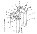
参照符号1により、図1および2において、ビームブランク形態の鋳型管体が、示されている。
【0021】
この鋳型管体1は、全周囲にわたって一定の管壁2の厚さDを有する、二重T字形の断面を備えている。
【0022】
鋳型管体1の内側輪郭3は、鋳込みストランドの断面を規定している。
【0023】
鋳造の際に生じる熱を導出するために、管壁2内に、鋳型管体1の全長Lにわたって延在する冷却管路4が装入されており、これら冷却管路は、矢印KWに従って、下から上へと、冷却水でもって作用可能である。即ち、これら冷却管路4は、管壁2の端面5内において終わっており、その際、ただ一方の端面5だけが認識可能である。
【0024】
冷却管路4は、穿孔処理によって、しかも鋳型管体1が湾曲される前に、管壁2内に装入される。この湾曲によって、これら冷却管路4は、部分的に、その場合に、内側輪郭3に向かってより大きな表面領域が形成されるように長円形に変形し、このことによって、熱導出が改良される。
【0025】
鋳型管体1の特別の内側輪郭3は、一方ではフランジ領域7をおよび他方ではウェブ領域8を区画する壁部分9の間で、丸くされた移行部6を備えている。これら移行部6内において互いに隣接する、2つの冷却管路4の間隔Aは、残りの壁部分9内における間隔Bよりもより小さい。
【0026】
図1および2の実施例において、冷却管路4が、鋳型管体1をこの鋳型管体の全長Lにわたって貫通しているのに対して、移行部6内において設けられた冷却管路4が、管壁2の上側の端面5から、ほぼこの管壁2の中間の高さ領域に至るまで延在することも、同様に可能である。これら冷却管路4は、冷却循環を形成するために、これら冷却管路の上側の端面において、互いに結合されており、且つ、管壁2の中間の高さ領域における冷却媒体供給部および冷却媒体導出部を介して、冷却媒体を供給される。
【0027】
付加的に、鋳型管体1は、管壁2の外側輪郭10に適合された水案内ジャケットの中へ埋設されており、従って、この鋳型管体1は、全体で、冷却媒体でもって貫通流動された冷却間隙によって囲繞されている。
【0028】
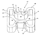
図3は、多少異なる透視の状態での、ビームブランク形態における内側輪郭12を有し、同様に一方ではフランジ領域14をおよび他方ではウェブ領域15を区画する壁部分16の間で、丸くされた移行部13を有する、鋳型管体11の更なる実施形態を示している。この実施例の場合、冷却管路4は、ただ移行部領域13内だけにおいて存在している。全鋳型管体11は、詳細には図示されていない方法で、この管壁18の外側輪郭17に適合された水案内ジャケットの中へ埋設されており、この水案内ジャケットを介して、残りの壁部分16およびこれら冷却管路4を備えた移行部領域が冷却される。
【図面の簡単な説明】
【図1】 透視の状態での、ビームブランク形態における鋳型管体の上側の端部分の図である。
【図2】 異なる透視の状態での、多少延長された図示における図1の鋳型管体の図である。
【図3】 更なる実施形態による、ビームブランク形態における鋳型管体の上側の端部分の図である。
【符号の説明】
1 鋳型管体
2 鋳型管体1の管壁
3 鋳型管体1の内側輪郭
4 冷却管路
5 管壁2の端面
6 フランジ領域7とウェブ領域8の間の移行部
7 フランジ領域
8 ウェブ領域
9 壁部分
10 鋳型管体1の外側輪郭
11 鋳型管体
12 鋳型管体11の内側輪郭
13 フランジ領域14とウェブ領域15の間の移行部
14 フランジ領域
15 ウェブ領域
16 管壁18の壁部分
17 管壁18の外側輪郭
18 管壁
A 間隔
B 間隔
D 管壁2の厚さ
L 鋳型管体1の長さ
KW 冷却水、 冷却媒体、 矢印[0001]
BACKGROUND OF THE INVENTION
The invention relates to a mold tube for continuously casting metal according to the features of the superordinate concept of
[0002]
[Prior art]
It is known to incorporate a mold tube into a water guide jacket to derive the heat generated during continuous casting of metal. In this case, based on the inner dimensions of the water guide jacket on the one hand and on the other hand the outer dimensions of the mold tube, a precisely defined thermo-engineered gap is formed, from below through the gap. The cooling water flows to the heat source, and the heat generated by the cooling water is accommodated and carried out. If the mold tube is used in the form of a beam blank, therefore, the inner profile of the water guide jacket must likewise match the outer profile of such a mold.
[0003]
The heat derivation using the cooling water is further defined by the water velocity in the gap between the mold tube and the water guide jacket. This gap, however, expands on the occasion of each recalibration of the mold tube, due to wear resulting from wear and the reduction in mold tube wall thickness that is forcibly induced by this wear. . This widening of the water gap, however, is accompanied by a reduction in the speed of the water and thus also a reduction in the heat extraction.
[0004]
From GB 954 719 it is known to provide a mold for continuous casting of metal with cooling perforations extending in the longitudinal and transverse directions of the mold tube. In the case of a mold tube in the form of a beam blank, however, there is a problem that cooling perforations are formed in the mold tube in a direction transverse to the longitudinal extension, with a high cost. In addition, in a special geometric shape in the form of a beam blank, an extreme local heat load is generated at the transition between the wall portions defining the flange region on the one hand and the web region on the other hand. This local heat load induces a dramatic reduction in mold tube overheating and lifetime of the mold tube in the unfavorable geometric transition state.
[0005]
[Problems to be solved by the invention]
Therefore, starting from this known technology, the problem underlying the present invention is to provide a mold tube for continuous casting of metal, which has an improved service life. And local overheating is avoided in this mold pipe body.
[0006]
[Means for Solving the Problems]
The first solution to this problem is in the characterizing part of
[0007]
According to the features of
[0008]
In connection with the above, first of all the advantage is obtained that essentially no water guide jacket has to be provided which is to be adapted to the outer contour of the tubular mold. This clear reduction in manufacturing costs is observed especially in the case of mold tubes in the form of beam blanks.
[0009]
With the derivation of heat through the cooling line in the tube wall, any changing heat derivation conditions no longer occur. The number of recalibrations does not affect the cooling performance.
[0010]
The cooling pipe basically goes out at the end face of the pipe wall in all wall portions. Performing welding in this area is possible without problems due to trouble-free integration after recalibration and reliable mold tube sealing, in which case this welding is then performed with this recalibration. Later, it is easily post-processed to new dimensions.
[0011]
If the cooling line has a circular cross section, the further advantage of the large number of cooling line cross-sections being also oval in this case is more particularly that the surface area is a cast pipe. Given to the beam blank configuration after bending of the tubular mold in the sense that it expands towards the path and therefore allows for relatively high heat derivation.
[0012]
The second solution is in the characterizing part of
[0013]
According to the features of
[0014]
It is possible for the cooling conduit provided in the transition to extend from the upper end face of the tube wall to a substantially intermediate height region of the tube wall. This results in a strong heat derivation in the locally thermally strongly loaded wall portion (claim 4).
[0015]
According to the first or second aspect , the cooling medium supply section and the cooling medium outlet section connected to the cooling pipe line are provided in the outer contour of the pipe wall. The cooling medium supply part and the cooling medium outlet part are particularly preferably provided in the intermediate height region of the outer contour of the tube wall ( claim 5 ). In order to form a cooling line system, the cooling lines introduced from the end faces of the pipe walls are closed and connected to one another via an overflow line.
[0016]
In order to cool the mold tube, it is basically possible for the cooling medium supply and the cooling medium outlet to be connected to separate cooling circulations. Advantageously, however, the cooling medium flowing between the tube wall and the water guide jacket will also flow through the cooling line and will result in a strong heat derivation in the thermally higher load region. ( Claim 6 ). Appropriate guiding means are provided on the outer contour of the tube wall and / or on this water guide jacket in order to facilitate coolant penetration into the cooling line from the gap between the water guide jacket and the tube wall. These guiding means guide the flow of the cooling medium into the cooling pipes.
[0017]
The feature according to the invention is particularly advantageous in accordance with
[0018]
The mold tube is advantageously made of copper or a copper alloy.
[0019]
Next, the present invention will be described in detail based on the embodiments specifically described in the drawings.
[0020]
DETAILED DESCRIPTION OF THE INVENTION
By means of
[0021]
The
[0022]
The
[0023]
In order to derive the heat generated during the casting, cooling
[0024]
The
[0025]
The special
[0026]
In the embodiment of FIGS. 1 and 2, the
[0027]
In addition, the
[0028]
FIG. 3 has an
[Brief description of the drawings]
FIG. 1 is a view of the upper end portion of a mold tube in the form of a beam blank in a transparent state.
FIG. 2 is a view of the mold tube of FIG. 1 in a slightly extended view, with different perspectives.
FIG. 3 is a view of the upper end portion of the mold tube in the form of a beam blank, according to a further embodiment.
[Explanation of symbols]
DESCRIPTION OF
Claims (7)
その際、この内側輪郭(3)が、外側から供給された冷却媒体(KW)によって間接的に冷却可能であり、
且つその際、この管壁(2)内において、この管壁の長手方向で延在する冷却管路(4)が設けられている様式の上記鋳型管体において、
これら移行部内(6)において互いに隣接する、2つの冷却管路(4)の間隔(A)は、残りの壁部分(9)内における間隔(B)よりもより小さく構成されていること、
移行部(6)内において設けられた冷却管路(4)は、管壁(2)の上側の端面(5)から、ほぼこの管壁(2)の中間の高さ領域に至るまで延在すること、
を特徴とする鋳型管体。A mold tube for continuous casting of metal, the wall portion (9) of which the tube wall (2) defines a flange region (7) on the one hand and a web region (8) on the other hand An inner profile (3) in the form of a beam blank with a rounded transition (6),
The inner contour (3) can then be cooled indirectly by the cooling medium ( KW ) supplied from the outside,
And in that case, in the above-mentioned mold pipe body in a mode in which a cooling pipe line (4) extending in the longitudinal direction of the pipe wall is provided in the pipe wall (2),
The interval (A) between the two cooling pipes (4) adjacent to each other in these transition portions (6) is configured to be smaller than the interval (B) in the remaining wall portion (9),
The cooling pipe (4) provided in the transition part (6) extends from the upper end surface (5) of the pipe wall (2) to a height region substantially in the middle of the pipe wall (2). To do,
A mold tube characterized by.
その際、この内側輪郭(12)が、外側から供給された冷却媒体(KW)によって間接的に冷却可能であり、
且つその際、この管壁(18)内において、この管壁の長手方向に延在する冷却管路(4)が設けられている様式の上記鋳型管体において、
冷却管路(4)は、ただ丸くされた移行部(13)内においてだけ設けられており、且つ、残りの壁部分(16)並びに丸くされた移行部(13)が、管壁(18)の外側輪郭(17)に適合された水案内ジャケットを介して冷却可能であるように構成されていること、
移行部(13)内において設けられた冷却管路(4)は、管壁(18)の上側の端面(5)から、ほぼこの管壁(18)の中間の高さ領域に至るまで延在すること、
を特徴とする鋳型管体。A mold tube for continuously casting metal, the wall portion (16) of which the tube wall (18) defines a flange region (14) on the one hand and a web region (15) on the other hand An inner profile (12) in the form of a beam blank with a rounded transition (13),
In this case, the inner contour (12) can be indirectly cooled by the cooling medium (KW) supplied from the outside,
In this case, in the mold pipe body in a mode in which the cooling pipe line (4) extending in the longitudinal direction of the pipe wall is provided in the pipe wall (18),
The cooling line (4) is provided only in the rounded transition (13), and the remaining wall portion (16) as well as the rounded transition (13) is connected to the pipe wall (18). Being configured to be coolable via a water guide jacket adapted to the outer contour (17) of
The cooling pipe (4) provided in the transition part (13) extends from the upper end surface (5) of the pipe wall (18) to a height region substantially in the middle of the pipe wall (18). To do,
A mold tube characterized by.
Applications Claiming Priority (2)
| Application Number | Priority Date | Filing Date | Title |
|---|---|---|---|
| DE10160135.2 | 2001-12-07 | ||
| DE10160135A DE10160135A1 (en) | 2001-12-07 | 2001-12-07 | Mold tube for the continuous casting of metals |
Publications (2)
| Publication Number | Publication Date |
|---|---|
| JP2003170250A JP2003170250A (en) | 2003-06-17 |
| JP4278367B2 true JP4278367B2 (en) | 2009-06-10 |
Family
ID=7708358
Family Applications (1)
| Application Number | Title | Priority Date | Filing Date |
|---|---|---|---|
| JP2002344045A Expired - Lifetime JP4278367B2 (en) | 2001-12-07 | 2002-11-27 | Mold tube for continuous casting of metal |
Country Status (15)
| Country | Link |
|---|---|
| US (2) | US6736202B2 (en) |
| EP (1) | EP1317978B1 (en) |
| JP (1) | JP4278367B2 (en) |
| KR (1) | KR20030047781A (en) |
| CN (1) | CN1261257C (en) |
| AT (1) | ATE353256T1 (en) |
| BR (1) | BR0204987A (en) |
| CA (1) | CA2412202C (en) |
| DE (2) | DE10160135A1 (en) |
| DK (1) | DK1317978T3 (en) |
| ES (1) | ES2277610T3 (en) |
| MX (1) | MXPA02012104A (en) |
| PT (1) | PT1317978E (en) |
| RU (1) | RU2302312C2 (en) |
| TW (1) | TWI244952B (en) |
Families Citing this family (17)
| Publication number | Priority date | Publication date | Assignee | Title |
|---|---|---|---|---|
| DE10203967A1 (en) * | 2002-01-31 | 2003-08-14 | Km Europa Metal Ag | Mold pipe |
| DE10337205A1 (en) * | 2003-08-13 | 2005-03-10 | Km Europa Metal Ag | Liquid-cooled mold |
| EP1918042A1 (en) * | 2006-10-10 | 2008-05-07 | Concast Ag | Mould for continuous casting of pre-profiled billets |
| JP5057312B2 (en) | 2006-12-14 | 2012-10-24 | シーティーエー・テクノロジー・プロプリエタリー・リミテッド | Multi-channel copper pipe manufacturing method and apparatus for manufacturing the pipe |
| US20100313589A1 (en) * | 2009-06-13 | 2010-12-16 | Brent Alden Junge | Tubular element |
| US20120138281A1 (en) * | 2010-12-06 | 2012-06-07 | Transistor Devices, Inc. D/B/A Tdi Power | Heat Exchanger for Electronic Assemblies |
| DE202012004204U1 (en) * | 2011-05-03 | 2012-06-15 | Central Iron & Steel Research Institute | Bevelled narrow-side copper plate for casting mold with funnel-shaped curved surface |
| CN102335728B (en) * | 2011-10-26 | 2013-07-17 | 中冶南方工程技术有限公司 | Continuous casting crystallizer for H-shaped special-shaped blank |
| CN102962415B (en) * | 2012-12-14 | 2015-05-13 | 莱芜钢铁集团有限公司 | H-shaped combined crystallizer |
| US9295185B2 (en) | 2013-03-13 | 2016-03-22 | Transistor Devices, Inc. | Sealed enclosure for power electronics incorporating a heat exchanger |
| US9516794B2 (en) | 2014-10-31 | 2016-12-06 | Transistor Devices, Inc. | Modular scalable liquid cooled power system |
| KR101914083B1 (en) * | 2016-11-30 | 2018-11-01 | 주식회사 포스코 | Mold and Manufacturing method thereof |
| KR102100794B1 (en) * | 2018-08-02 | 2020-04-14 | 주식회사 포스코 | Mold |
| CN110252983B (en) * | 2019-06-17 | 2021-03-30 | 山东钢铁股份有限公司 | Method for controlling cracks of micro-alloy steel near-net-shape special-shaped continuous casting billet |
| CN112170794B (en) * | 2020-09-30 | 2022-03-08 | 江苏华龙铸铁型材有限公司 | Combined type abdomen cooling crystallizer for producing track section bar |
| CN114322574B (en) * | 2021-12-22 | 2023-12-12 | 芜湖福记恒机械有限公司 | Special-shaped copper water jacket in flash furnace and casting forming process thereof |
| DE102022208478A1 (en) * | 2022-08-16 | 2024-02-22 | Sms Group Gmbh | Copper plate with local intensive cooling zones |
Family Cites Families (17)
| Publication number | Priority date | Publication date | Assignee | Title |
|---|---|---|---|---|
| US2169893A (en) * | 1937-11-01 | 1939-08-15 | Chase Brass & Copper Co | Cooling means for continuous casting apparatus |
| GB954719A (en) | 1962-04-02 | 1964-04-08 | Continuous Casting Company Ltd | Improvements in the construction of continuous casting moulds |
| US3853309A (en) * | 1972-03-20 | 1974-12-10 | C Widmer | Components using cast-in cooling tubes |
| US3991822A (en) * | 1973-03-22 | 1976-11-16 | Olin Corporation | Metal tube having internal passages therein |
| JPS5213428A (en) * | 1975-07-23 | 1977-02-01 | Kawasaki Steel Co | Continuous casting for beam blanks |
| GB1524342A (en) * | 1977-01-12 | 1978-09-13 | Inst Elektroswarki Patona | Mould for electroslag casting of polygonal ingots |
| DE2740933C2 (en) * | 1977-09-10 | 1982-11-25 | GNS Gesellschaft für Nuklear-Service mbH, 4300 Essen | Transport and storage containers for radioactive substances, especially irradiated nuclear reactor fuel elements |
| JPS5775254A (en) * | 1980-10-29 | 1982-05-11 | Nippon Steel Corp | Method for continuous casting of beam blank and mold for this |
| US5314008A (en) * | 1992-05-22 | 1994-05-24 | Foster Wheeler Energy Corporation | Fluid-cooled jacket for an air-swept distributor |
| US5513691A (en) * | 1994-02-02 | 1996-05-07 | Sms Concast Inc. | Mold for continuous casting and method of making the mold |
| JPH0999345A (en) * | 1995-10-04 | 1997-04-15 | Nomura Tokin:Kk | Mold for casting beam blank |
| DE19622424C2 (en) * | 1996-06-04 | 1998-10-29 | Martin Umwelt & Energietech | Grate element and grate with liquid cooling |
| JP4578586B2 (en) * | 1998-02-16 | 2010-11-10 | 中越合金鋳工株式会社 | Continuous casting mold for beam blank slab |
| DE19859040A1 (en) * | 1998-12-21 | 2000-06-29 | Km Europa Metal Ag | Mold tube and method for recalibrating a mold tube |
| IT1310518B1 (en) * | 1999-01-13 | 2002-02-18 | Danieli Off Mecc | DEVICE FOR CONTINUOUS HIGH SPEED CASTING AND RELATED PROCESS |
| IT1310517B1 (en) * | 1999-01-13 | 2002-02-18 | Danieli Off Mecc | CONTINUOUS CASTING CRYSTALLIZER |
| US6612363B1 (en) * | 2002-06-10 | 2003-09-02 | Sms Demag Inc. | Beam blank mold for continuous casting |
-
2001
- 2001-12-07 DE DE10160135A patent/DE10160135A1/en not_active Withdrawn
-
2002
- 2002-11-19 CA CA002412202A patent/CA2412202C/en not_active Expired - Lifetime
- 2002-11-21 US US10/301,102 patent/US6736202B2/en not_active Expired - Lifetime
- 2002-11-27 JP JP2002344045A patent/JP4278367B2/en not_active Expired - Lifetime
- 2002-12-03 AT AT02027024T patent/ATE353256T1/en active
- 2002-12-03 EP EP02027024A patent/EP1317978B1/en not_active Expired - Lifetime
- 2002-12-03 PT PT02027024T patent/PT1317978E/en unknown
- 2002-12-03 ES ES02027024T patent/ES2277610T3/en not_active Expired - Lifetime
- 2002-12-03 DK DK02027024T patent/DK1317978T3/en active
- 2002-12-03 DE DE50209433T patent/DE50209433D1/en not_active Expired - Lifetime
- 2002-12-04 TW TW091135175A patent/TWI244952B/en not_active IP Right Cessation
- 2002-12-05 BR BR0204987-2A patent/BR0204987A/en not_active Application Discontinuation
- 2002-12-06 RU RU2002132960/02A patent/RU2302312C2/en active
- 2002-12-06 CN CNB021545723A patent/CN1261257C/en not_active Expired - Lifetime
- 2002-12-06 KR KR1020020077139A patent/KR20030047781A/en not_active Application Discontinuation
- 2002-12-06 MX MXPA02012104A patent/MXPA02012104A/en active IP Right Grant
-
2004
- 2004-04-07 US US10/819,637 patent/US6942012B2/en not_active Expired - Lifetime
Also Published As
| Publication number | Publication date |
|---|---|
| US20040188056A1 (en) | 2004-09-30 |
| JP2003170250A (en) | 2003-06-17 |
| MXPA02012104A (en) | 2004-10-15 |
| TWI244952B (en) | 2005-12-11 |
| DE50209433D1 (en) | 2007-03-22 |
| RU2302312C2 (en) | 2007-07-10 |
| CN1422714A (en) | 2003-06-11 |
| US6736202B2 (en) | 2004-05-18 |
| CA2412202C (en) | 2009-08-25 |
| ATE353256T1 (en) | 2007-02-15 |
| ES2277610T3 (en) | 2007-07-16 |
| US6942012B2 (en) | 2005-09-13 |
| TW200300713A (en) | 2003-06-16 |
| KR20030047781A (en) | 2003-06-18 |
| US20030106681A1 (en) | 2003-06-12 |
| BR0204987A (en) | 2004-06-29 |
| DK1317978T3 (en) | 2007-06-04 |
| PT1317978E (en) | 2007-03-30 |
| DE10160135A1 (en) | 2003-06-18 |
| EP1317978B1 (en) | 2007-02-07 |
| CN1261257C (en) | 2006-06-28 |
| CA2412202A1 (en) | 2003-06-07 |
| EP1317978A1 (en) | 2003-06-11 |
Similar Documents
| Publication | Publication Date | Title |
|---|---|---|
| JP4278367B2 (en) | Mold tube for continuous casting of metal | |
| US7549463B1 (en) | Cooling panel for a furnace for producing iron or steel | |
| JP5046626B2 (en) | Mold tube for continuous casting of metal | |
| JPS63140743A (en) | Mold for continuously casting steel strip | |
| RU2002132960A (en) | TUBULAR CRYSTALIZER FOR CONTINUOUS METAL CASTING (OPTIONS) | |
| JP5256376B2 (en) | Method of manufacturing cooling element for dry metallurgical reactor and cooling element | |
| US20070068664A1 (en) | Method of manufacturing a cooling plate and a cooling plate manufactured with this method | |
| GB2177331A (en) | Continuous casting mould | |
| JP2003225741A (en) | Mold tube | |
| AU2001289934B2 (en) | Cooling element for shaft furnaces | |
| JPH035056A (en) | Injection container for hot chamber die cast machine | |
| JP4318506B2 (en) | Mold tube | |
| JP4568013B2 (en) | Continuous casting mold | |
| JP2005207726A (en) | Heat exchanger and manufacturing method therefor | |
| JP3702866B2 (en) | Stave cooler and metal refining method using the same | |
| JP2019513905A (en) | Shot lance tip | |
| JPH0676639U (en) | Cylinder block structure | |
| EP1153255B1 (en) | Pyrometallurgical reactor cooling element and its manufacture | |
| JP2001271116A (en) | Structure for cooling core metal in immersion tube of rh degassing apparatus | |
| JPH04108943U (en) | Hollow continuous casting machine | |
| JP2006326653A (en) | Water-cooled mold for continuous casting |
Legal Events
| Date | Code | Title | Description |
|---|---|---|---|
| A621 | Written request for application examination |
Free format text: JAPANESE INTERMEDIATE CODE: A621 Effective date: 20050707 |
|
| A977 | Report on retrieval |
Free format text: JAPANESE INTERMEDIATE CODE: A971007 Effective date: 20080512 |
|
| A131 | Notification of reasons for refusal |
Free format text: JAPANESE INTERMEDIATE CODE: A131 Effective date: 20080603 |
|
| A601 | Written request for extension of time |
Free format text: JAPANESE INTERMEDIATE CODE: A601 Effective date: 20080902 |
|
| A602 | Written permission of extension of time |
Free format text: JAPANESE INTERMEDIATE CODE: A602 Effective date: 20080905 |
|
| A521 | Request for written amendment filed |
Free format text: JAPANESE INTERMEDIATE CODE: A523 Effective date: 20081127 |
|
| A711 | Notification of change in applicant |
Free format text: JAPANESE INTERMEDIATE CODE: A711 Effective date: 20081219 |
|
| TRDD | Decision of grant or rejection written | ||
| A01 | Written decision to grant a patent or to grant a registration (utility model) |
Free format text: JAPANESE INTERMEDIATE CODE: A01 Effective date: 20090303 |
|
| A01 | Written decision to grant a patent or to grant a registration (utility model) |
Free format text: JAPANESE INTERMEDIATE CODE: A01 |
|
| A61 | First payment of annual fees (during grant procedure) |
Free format text: JAPANESE INTERMEDIATE CODE: A61 Effective date: 20090310 |
|
| FPAY | Renewal fee payment (event date is renewal date of database) |
Free format text: PAYMENT UNTIL: 20120319 Year of fee payment: 3 |
|
| R150 | Certificate of patent or registration of utility model |
Ref document number: 4278367 Country of ref document: JP Free format text: JAPANESE INTERMEDIATE CODE: R150 Free format text: JAPANESE INTERMEDIATE CODE: R150 |
|
| FPAY | Renewal fee payment (event date is renewal date of database) |
Free format text: PAYMENT UNTIL: 20120319 Year of fee payment: 3 |
|
| FPAY | Renewal fee payment (event date is renewal date of database) |
Free format text: PAYMENT UNTIL: 20130319 Year of fee payment: 4 |
|
| R250 | Receipt of annual fees |
Free format text: JAPANESE INTERMEDIATE CODE: R250 |
|
| FPAY | Renewal fee payment (event date is renewal date of database) |
Free format text: PAYMENT UNTIL: 20130319 Year of fee payment: 4 |
|
| FPAY | Renewal fee payment (event date is renewal date of database) |
Free format text: PAYMENT UNTIL: 20140319 Year of fee payment: 5 |
|
| R250 | Receipt of annual fees |
Free format text: JAPANESE INTERMEDIATE CODE: R250 |
|
| S533 | Written request for registration of change of name |
Free format text: JAPANESE INTERMEDIATE CODE: R313533 |
|
| R350 | Written notification of registration of transfer |
Free format text: JAPANESE INTERMEDIATE CODE: R350 |
|
| R250 | Receipt of annual fees |
Free format text: JAPANESE INTERMEDIATE CODE: R250 |
|
| R250 | Receipt of annual fees |
Free format text: JAPANESE INTERMEDIATE CODE: R250 |
|
| R250 | Receipt of annual fees |
Free format text: JAPANESE INTERMEDIATE CODE: R250 |
|
| R250 | Receipt of annual fees |
Free format text: JAPANESE INTERMEDIATE CODE: R250 |
|
| R250 | Receipt of annual fees |
Free format text: JAPANESE INTERMEDIATE CODE: R250 |
|
| R250 | Receipt of annual fees |
Free format text: JAPANESE INTERMEDIATE CODE: R250 |
|
| R250 | Receipt of annual fees |
Free format text: JAPANESE INTERMEDIATE CODE: R250 |
|
| S533 | Written request for registration of change of name |
Free format text: JAPANESE INTERMEDIATE CODE: R313533 |
|
| R350 | Written notification of registration of transfer |
Free format text: JAPANESE INTERMEDIATE CODE: R350 |
|
| R250 | Receipt of annual fees |
Free format text: JAPANESE INTERMEDIATE CODE: R250 |
|
| S111 | Request for change of ownership or part of ownership |
Free format text: JAPANESE INTERMEDIATE CODE: R313111 |
|
| R350 | Written notification of registration of transfer |
Free format text: JAPANESE INTERMEDIATE CODE: R350 |
|
| R250 | Receipt of annual fees |
Free format text: JAPANESE INTERMEDIATE CODE: R250 |
|
| S111 | Request for change of ownership or part of ownership |
Free format text: JAPANESE INTERMEDIATE CODE: R313113 |
|
| R350 | Written notification of registration of transfer |
Free format text: JAPANESE INTERMEDIATE CODE: R350 |
|
| EXPY | Cancellation because of completion of term |