JP4273549B2 - Low melting glass fine powder and photosensitive paste - Google Patents
Low melting glass fine powder and photosensitive paste Download PDFInfo
- Publication number
- JP4273549B2 JP4273549B2 JP33727698A JP33727698A JP4273549B2 JP 4273549 B2 JP4273549 B2 JP 4273549B2 JP 33727698 A JP33727698 A JP 33727698A JP 33727698 A JP33727698 A JP 33727698A JP 4273549 B2 JP4273549 B2 JP 4273549B2
- Authority
- JP
- Japan
- Prior art keywords
- particle size
- photosensitive
- powder
- paste
- glass
- Prior art date
- Legal status (The legal status is an assumption and is not a legal conclusion. Google has not performed a legal analysis and makes no representation as to the accuracy of the status listed.)
- Expired - Lifetime
Links
Images


Description
【0001】
【発明の属する技術分野】
本発明は、新規な無機微粉末、それを用いた感光性ペースト、より詳細にはプラズマディスプレイパネル(以下PDPと略す)やプラズマアドレス液晶や電子放出素子(Field Emission Display(FED)、電界放射型表示管、表面伝導型電子放出素子ともいう)などのディスプレイパネルにおける隔壁(リブ、スペーサともいう)形成用の感光性ペーストおよびそれらの製造方法に関するものである。
【0002】
【従来の技術】
近年、回路材料やディスプレイにおいて、小型・高精細化が進んでおり、それに伴って、パターン加工技術の向上が望まれている。特に、プラズマディスプレイパネルの各画素の仕切である隔壁の形成には、ガラスなどの無機材料を高精度かつ高アスペクト比でパターン加工できる技術が求められている。
【0003】
プラズマディスプレイパネル(PDP)は高速の表示が可能であり、且つ大型化が容易であることから、OA機器および広報表示装置などの分野に浸透している。また高品位テレビジョンの分野などでの進展が非常に期待されている。
【0004】
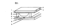
このような用途の拡大にともなって、微細で多数の表示セルを有するカラーPDPが注目されている。PDPは、前面ガラス基板と背面ガラス基板との間に備えられた放電空間内で対向するアノードおよびカソード電極間にプラズマ放電を生じさせ、上記放電空間内に封入されているガスから発生した紫外線を、放電空間内に設けた蛍光体にあてることにより表示を行うものである。AC方式PDPの構造例を図1に示す。背面板には、放電空間の確保と電極間距離の規定および誤放電防止の役割を果たすために、白色または黒色の隔壁が設けられている。AC方式PDPの場合、隔壁はストライプ状に形成される。
【0005】
PDPを高精細化するためには、1画素の大きさを小さくする必要がある。この場合、上記の隔壁のピッチおよび線幅を狭くする必要がある。具体的には、42インチハイビジョンテレビ(1920×1035画素)や23インチのOA用モニター(XGA:1024×768画素)を実現しようとすると、隔壁はピッチ150μm、幅20〜40μm、高さ60〜170μm程度で形成する必要がある。通常、隔壁は背面ガラス基板にガラスからなる絶縁ペーストをスクリーン印刷法で塗布・乾燥し、この塗布・乾燥工程を10回以上も繰り返して所定の高さにした後、焼成して形成している。しかしながら、通常のスクリーン印刷法では、特にパネルサイズが大型化した場合に、予め前面基板上に形成された放電電極と絶縁ガラスペーストの印刷場所との位置合わせが難しく、位置精度が得られ難いという問題がある。しかも10回以上ガラスペーストを重ね合わせ塗布を行うことになるため、隔壁および壁体の側面エッジ部の波打ちや裾の乱れが生じ、高さの精度が得られないため、表示品質が悪くなり、また作業性が悪い、歩留まりが低いなどの問題もある。特に、パターン線幅が50μm、ピッチが150μm以下になると隔壁底部がペーストのチクソトロピー性により滲みやすく、シャープで残渣のない隔壁形成が難しくなる問題がある。
【0006】
PDPの大面積化、高解像度化に伴い、このようなスクリーン印刷による方法では、高アスペクト比、高精細の隔壁の製造がますます技術的に困難となり、かつコスト的に不利になってきている。
【0007】
これらの問題を改良する方法として、特開平1−296534号公報、特開平2−165538号公報、特開平5−342992号公報、特開平6−295676号公報では、隔壁を感光性ペーストを用いてフォトリソグラフィ技術により形成する方法が提案されている。しかしながら、これらの方法では、感光性絶縁ペーストのガラス含有量が少ないために焼成後に緻密な隔壁が得られなかったり、感光性ペーストの感度や解像度が低いという問題があった。このために高アスペクト比の隔壁を得るためには、スクリーン印刷・露光・現像の工程を繰り返し行うことが必要であった。しかし、印刷・露光・現像を繰り返し行うのでは、位置合わせの問題が生じたり、コストの問題があり限界があった。
【0008】
特開平8−50811号公報では、感光性ガラスペースト法を用いて、隔壁を1回の露光で形成する方法が提案されている。しかしながら、この方法では、ピッチが200μm以下、隔壁の線幅が50μm以下の高精細隔壁を作製する際、感光性ペースト中の無機成分と有機成分の割合によって、露光量マージンが狭く線幅の太りや残膜、隔壁の蛇行等が発生する問題があった。露光量マージンとは、露光量過多による線幅の太りや残膜、露光量不足による隔壁の蛇行が生じない適正露光量の範囲である。線幅の太りや残膜が発生すると放電空間が狭くなり放電特性が落ち、表示ムラになる。また、隔壁が蛇行すると蛍光体塗布が均一に行えず、混色が起きたりし、歩留まりが悪くなる問題があった。
【0009】
【発明が解決しようとする課題】
本発明は、上記のような欠点のない、高アスペクト比且つ高精度のパターンを形成したディスプレイの提供を目的とするものである。
【0010】
【課題を解決するための手段】
本発明の目的は、感光性ペースト用の低融点ガラス微粉末であって、該低融点ガラス微粉末の粒度分布が少なくとも2つ以上のピークを有することを特徴とする低融点ガラス微粉末、およびそれを用いた感光性ペーストによって達成される。
【0011】
【発明の実施の形態】
本発明の無機微粉末は、無機粉末と感光性有機成分からなる感光性ペーストに用いられ、該感光性ペーストを塗布、乾燥、露光、現像および焼成することによってプラズマディスプレイパネル、プラズマアドレス液晶ディスプレイパネルまたは電子放出素子などの隔壁を形成することができる。得られる隔壁は、無機微粉末の焼結体である。
【0012】
感光性ペーストで形成しようとする隔壁は、高さが60〜170μmであり、焼成収縮を考慮すると隔壁パターン形成のために塗布される感光性ペーストの塗布膜の厚みは100〜220μmあることが必要となる。
【0013】
このような厚みの感光性ペースト塗布膜に高精細なパターンを露光し、高アスペクト比のパターンを解像度高く形成するためには、露光用の活性光線を塗布膜の最下部までできるだけ多く透過させることが必須である。具体的には、感光性ペーストは、50μm厚みの塗布膜で測定した全光線透過率が50%以上であることが好ましい。この場合、測定波長は、ペーストを塗布後、露光する光の波長で測定することが効果を確認する上で正確である。
【0014】
このため、感光性ペーストに配合される無機微粉末および感光性有機成分として共に光透過性の高いものを選び、且つ、これらを均一に混合し、ペースト内部に気泡などの組成ムラが無いことが要求される。しかしながら、たとえこれらを満たしても、全光線透過率が高い感光性ペーストを得ることは困難であり、全光線透過率が低いと露光用の活性光線が塗布膜の最下部まで十分に透過せず、高精細なパターンが形成できず、また、残膜を生じたり、隔壁パターンの蛇行を生じたりし、ディスプレイを製造した際に、輝度が低下したり、輝度ムラを生じたりする。
【0015】
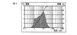
本発明では鋭意検討の結果、無機微粉末の粒度分布を、縦軸を頻度(%)、横軸を粒子径(μm)としたヒストグラムで示したとき、粒度分布が少なくとも2つ以上のピーク(二山分布以上)を有する無機微粉末を感光性ペーストに用いることによって、感光性ペーストの塗布膜を形成した際に膜中の光散乱が抑制され、全光線透過率が高く、優れたパターン特性を示す感光性ペーストを得ることが出来ることを見いだした。本発明の無機微粉末の粒度分布の例を図2〜4に示す。本発明の無機微粉末は、粒度分布の山の頂点での粒子径および頻度は様々な組み合わせのものを用いることができる。
【0016】
本発明の無機微粉末は、調合原料の調製、溶融あるいは共沈法、熱分解法、加水分解法などの化学的合成、粉砕、分級および乾燥の工程を経て作製される。無機微粉末の具体的な態様としては、低融点ガラスからなるもの、低融点ガラス粉末と高融点ガラス粉末からなるもの、低融点ガラス粉末40〜90重量%とフィラー60〜10重量%からなるもの等が好ましく用いられる。
【0017】
本発明の無機微粉末の粒度分布は、上記の粉砕、分級工程において制御される。粉砕は、ボールミル、ジェットミル等の方法が用いられ、分級は、ふるい分け、気流式分級(ジェットミル)等の乾式分級で行う。得られた無機微粉末の粒度分布は、レーザー回折散乱法を利用した粒度分布計によって測定することができる。無機微粉末が屈折率の異なる複数種の粉末からなる場合には、まず単独粉末それぞれをレーザー回折散乱法で測定し、その後、単独粉末の粒度分布と粉末の混合比から複合粉末の粒度分布を計算して求める。また、未知の複合粉末については、平均屈折率をベッケ法で測定し、この値を用いてレーザー回折散乱法により測定することができる。
【0018】
一般に、粒子の付着力は表面積に依存するため、粒子径の2乗に比例するのに対し、粒子の重量は体積に依存するため粒径の3乗に比例する。この結果、粒子径が小さいものほど、凝集しやすく、ペースト中に均一に分散されず、塗布膜を形成した際、空隙ができやすくなるので光透過性が低くなり、所望のパターン特性が得られない。一方、粒子径が大きすぎると、焼成温度によっては、焼成後の隔壁の頂部に凹凸が生じ、封着時に前面板との間に隙間が出来てクロストークが生じたりする。また、無機微粒子が放電空間に異物として残ったりする問題がある。本発明では、鋭意検討の結果、粒度分布が少なくとも2山であることに加え、平均粒子径および最大粒子径が以下の範囲である無機微粉末が、凝集性が少ないため、パターン形成性が一層向上した感光性ペーストを得ることができ、さらに焼成後の隔壁頂部の凹凸や異物の問題がないため、高精細隔壁形成に適していることを見いだした。
1.0μm≦平均粒子径≦7μm
最大粒子径≦40μm
平均粒子径(D50ともいう)を1.0μm以上とすることで粉末の凝集を抑え、良好なパターン形成性を得ることができる。7μm以下とすることで、焼成後の隔壁頂部の凹凸を抑制しクロストークを抑えることができる。より好ましい平均粒子径の範囲は、1.5〜6.5μm、さらに好ましくは2〜6μm、さらに好ましくは2〜5μmである。
【0019】
最大粒子径を40μm以下とすることで、焼成後の隔壁頂部の凹凸や放電空間内に異物が残る問題が生じない。また、最大粒子径は7μm以上とすることが好ましい。7μm以上とすることで、充填性が良く、パターン形成性も良好となる。最大粒子径は更には10〜30μmの範囲内であることが、粉末の充填性や隔壁頂部の凹凸を抑制するためにより好ましい。
【0020】
また、無機微粉末の体積粒子径が累積で10%および90%となるときの粒径を、それぞれD10およびD90としたとき、これらの値が以下のような範囲であると、凝集性が少なく充填性の良い無機微粉末を得ることが出来る。
0.5μm≦D10≦2μm
4μm≦D90≦20μm
D10を0.5μm以上とすることで粉末の凝集を抑え、凝集した粉末間の空隙による散乱を防ぐことにより高精細なパターンを得ることが出来る。2μm以下とすることで、分級時の歩留まりが良好に保たれ、焼成後の隔壁頂部の凹凸によるクロストーク等の問題がない。更に好ましいD10の範囲は、0.7〜1.5μmである。
【0021】
D90を4μm以上とすることで、充填性が良く、パターン形成性も良好となる。20μm以下とすることで、隔壁頂部の凹凸や放電空間に異物が残る問題が生じない。更に好ましいD90の範囲は、6〜15μmである。
【0022】
無機微粉末のうち、焼成工程での加熱温度以上の軟化点または融点を有するフィラーは、そのまま隔壁中または隔壁表面に残留するので、その平均粒子径および最大粒子径はより小さいことが好ましい。すなわち、これらフィラーの平均粒子径は1〜4μm、最大粒子径は25μm以下であることが好ましい。このような粒度分布を有するものを使用することにより、充填性および分散性を満足させて、塗布性およびパターン形成性の優れた感光性ペーストを構成することが可能になる。平均粒子径を4μm以下、最大粒子径を25μm以下とすることで、隔壁の頂部の凹凸を抑え、放電時のクロストークを防ぎ、歩留まりが向上する。また、フィラーの平均粒子径を1μm以上とすることで粉末の凝集を抑え、ペースト中での分散性が良好なものとなる。
【0023】
また、感光性ペースト用無機微粉末としては、タップ密度が0.6g/cm3以上、好ましくは0.65g/cm3以上であることが、充填性がよく、ペーストのパターン形成性が向上し、高精細の隔壁形成を行うことができる。タップ密度とは、JIS Z 2500(2045)に記載の通り、振動させた容器内の粉末の単位体積当たりの質量である。
【0024】
タップ密度は、低融点ガラスおよびフィラーとして選択された組成・成分に由来する材料の真比重と粉末自体のパッキング性に関係する粒度分布に関連するものである。タップ密度を0.6g/cm3以上とすることで、ペースト作製時の無機微粉末の充填性および分散性が良好となり、塗布性の優れたペーストが得られる。
【0025】
これまでに記述してきた諸特性を有する低融点ガラス粉末と高融点ガラス粉末もしくはフィラーとからなる無機微粉末と感光性有機成分を構成成分として本発明の感光性ペーストが構成される。
【0026】
本発明で用いる低融点ガラス粉末は、ガラス転移点、軟化点の低いガラス基板上にパターン形成するため、ガラス転移温度が400〜550℃、軟化点が450〜600℃のガラス材料を用いることが好ましい。ガラス転移点を550℃以下、軟化点を600℃以下とすることで、ガラス基板のガラス転移点以下での焼き付けを行うことができる。また、低融点ガラス粉末がより低い温度で溶融し焼結され焼成工程における消費エネルギーを減少し、タクトタイムを削減するので低コスト化に有効である。ガラス転移点を400℃以上、軟化点を450℃以上とすることで、感光性ペースト中の感光性有機成分が分解、気化する前にガラスが溶けることがなく、従って炭化物などが隔壁中に取り込まれることによる誤放電が生じない。より好ましくはガラス転移点は400〜500℃、軟化点は450〜550℃の範囲である。
【0027】
感光性ペーストに用いる無機微粉末の平均屈折率は、1.5〜1.8、より好ましくは1.5〜1.7、更に好ましくは1.5〜1.65の範囲内であると、活性光線の透過性が向上するので適切である。ここでの平均屈折率は、均一に混合、分散した無機微粉末をベッケ法によって測定した値である。感光性ペーストの必須成分である感光性有機成分として使用可能なほとんどの化合物の屈折率が、1.45〜1.75の範囲にあることから、無機微粉末が上記の範囲の平均屈折率を有することで、無機微粉末と感光性有機成分それぞれの平均屈折率が±0.05の範囲内で整合し、ペースト中の光散乱を抑制し、活性光線の透過性を向上することができる。従って、塗布・露光の回数を減らして高精細の隔壁パターン形成することが可能となる。
【0028】
ガラス基板上に焼き付けが可能で、平均屈折率が1.5〜1.8の無機微粉末を得るためには、酸化ナトリウム、酸化リチウム、酸化カリウム等のアルカリ金属の酸化物のうち少なくとも1種を2〜20重量%含有する低融点ガラス粉末を用いるのが好ましい。これにより、軟化点、熱膨張係数のコントロールが容易になるだけでなく、ガラスの平均屈折率を低くすることができるため、有機物との屈折率差を小さくすることが容易になる。2%以上とすることで、熱軟化温度の制御が容易となる。20%以下とすることで、放電時のアルカリ金属酸化物の蒸発による輝度低下を防ぐことができる。さらにアルカリ金属の酸化物の添加量はペーストの安定性向上の観点から、15重量%以下であることがより好ましい。
【0029】
また、ガラス微粒子中に、酸化アルミニウム、酸化バリウム、酸化カルシウム、酸化マグネシウム、酸化亜鉛、酸化ジルコニウムなど、特に酸化アルミニウム、酸化バリウム、酸化亜鉛を添加することにより、硬度や加工性を改良することができるが、熱軟化点、熱膨張係数、屈折率の制御の点からは、その含有量は40重量%以下が好ましい。
【0030】
酸化リチウムを含むガラス組成としては、酸化物換算表記で
酸化リチウム : 3〜15重量%
酸化珪素 :15〜50重量%
酸化ホウ素 :15〜40重量%
酸化バリウム : 2〜15重量%
酸化アルミニウム : 6〜25重量%
であることが好ましい。
【0031】
酸化リチウムが3〜15重量%配合されることによってガラス粉末の軟化点、熱膨張係数のコントロールが容易になるだけでなく、ガラスの平均屈折率を低くすることができる。ガラスの平均屈折率を低くできることは、有機成分との屈折率差を小さくすることが容易になるので重要な条件である。また、感光性ペーストの安定性を向上させる点から、酸化リチウムは15重量%以下が好ましく、より好ましくは10重量%以下、更に好ましくは8重量%以下である。
【0032】
酸化珪素は15〜50重量%配合されることが、ガラス層の緻密性、強度や安定性の点や熱膨張係数を所望の値とし、軟化点を低くし、基板への焼き付けを容易にする点で好ましい。
【0033】
酸化ホウ素は15〜40重量%配合されることが、ガラスの安定性、絶縁層の強度の点で好ましい。酸化硼素はガラス粉末を800〜1200℃付近の温度で溶融するため、さらに酸化珪素が多い場合でも電気絶縁性、強度、熱膨張係数、絶縁層の緻密性などの電気、機械および熱的特性を損なうことのないように、焼き付け温度を520〜580℃の範囲に制御するために配合されることが好ましい。
【0034】
酸化バリウムを2〜15重量%配合することは、焼き付け温度および電気絶縁性の制御、ガラス層の安定性や緻密性の点で好ましい。
【0035】
酸化アルミニウムが6〜25重量%配合されることは、ガラスの強度、ガラスの耐熱温度や緻密な絶縁層が得られやすい点で好ましい。酸化アルミニウムによってガラスの歪み点を高めることができる。
【0036】
低融点ガラス粉末が上記金属酸化物に加え、酸化カルシウム、酸化マグネシウムを配合したものであることが好ましい。
【0037】
酸化カルシウムは2〜10重量%の範囲で配合されるのが歪み点を適度に保つ点で好ましい。酸化カルシウムは、低融点ガラス粉末を溶融し易くするとともに熱膨張係数を制御することができる。
【0038】
酸化マグネシウムは1〜10重量%の範囲で配合されるのが好ましい。酸化マグネシウムは、低融点ガラス粉末を溶融し易くするとともに熱膨張係数を制御するために添加される。10重量%を超えるとガラスが失透する傾向がある。
【0039】
さらに、ガラス粉末中に酸化チタン、酸化ジルコニウムなどが配合されてもよいが、その量は2重量%以下であることが好ましい。特に酸化ジルコニウムは、軟化点、ガラス転移点および電気絶縁性を制御するのに効果がある。
【0040】
また、上記組成で、酸化リチウムの代わりに、酸化ナトリウム、酸化カリウムを用いても良いが、ペーストの安定性の点で、酸化リチウムが好ましい。
【0041】
感光性ペースト法に用いる無機微粉末の量は、無機微粉末と感光性有機成分の和に対して65〜90重量%であるのが好ましい。65重量%以上とすることで、焼成時の収縮を抑え、隔壁の断線、剥がれを防ぐことができる。またパターン太り、現像時の残膜の発生が起こりにくい。90重量%以下とすることで、感光性成分が十分な量となり、パターンの形成性が良好となる。焼成収縮率を低減するため、より好ましい無機微粉末の量は70〜80重量%である。本発明の無機微粉末は充填性が高いため、この量を達成することが出来る。
【0042】
本発明の感光性ペーストを構成する無機微粉末として、低融点ガラスと共にフィラーが好ましく用いられる。フィラーは、低融点ガラスの軟化点において溶融しない粉末であるものを用いる。これにより、隔壁パターンの体積収縮を抑制し、形状保持性が向上する。フィラーの配合比は、無機微粉末に対して10〜60重量%であることが好ましい。10重量%以上とすることで体積収縮抑制、形状保持の効果が得られ、60重量%以下とすることでガラス基板上での密着強度を保持し、焼き付けを容易に行うことができる。配合比は、より好ましくは20〜40重量%である。
【0043】
フィラーは、セラミックスまたは/および高融点ガラス粉末である。セラミック粉末は、アルミナ、ジルコニア、コーディエライト、ムライト、スピネル、チタニアおよびシリカの群から好ましく選ばれて用いられる。これらのセラミックスは高い融点を有する成分であり、高融点ガラス粉末と同様に隔壁パターンの焼成工程の温度では熱的に変化を受けず、隔壁中に分散して粉末状態のまま残留する。勿論、その存在により前記のフィラー添加の効果が得られるものである。さらに、これらのセラミックスのうち平均屈折率が1.5〜1.8の範囲のものを、低融点ガラス粉末と混合すると、平均屈折率1.5〜1.8の無機微粉末を得るのに好適である。さらに、低融点ガラス粉末との屈折率差が±0.05の範囲内のものを選定することが、活性光線の透過特性を向上するために望ましい。チタニア、ジルコニアなどの平均屈折率が1.8を越えるものは、感光性ペースト中で散乱要因となり、活性光線の透過を妨げ、パターン形成性を低下させるが、形成された隔壁が白色化し、蛍光体層からの発光を反射して表示の輝度を高める効果を発揮するため、少量添加することもできる。
【0044】
もう一つのフィラーの態様である高融点ガラスとしては、ガラス転移点570〜1200℃、軟化点620〜1200℃を有するものが好ましい。このような高融点ガラスは、酸化珪素および酸化アルミニウムをそれぞれ15重量%以上含有する組成を有するものが好ましく、これらの含有量合計が50重量%以上であることが必要な熱特性を得るのに有効である。例えば以下の酸化物換算組成を含有する高融点ガラス粉末は好ましく用いられるが、これに限定されるものではない。
【0045】
酸化珪素 15〜50重量%
酸化硼素 5〜20重量%
酸化アルミニウム 15〜50重量%
酸化バリウム 2〜10重量%
この高融点ガラス粉末と前記のセラミックスとを同時にフィラーとして用いることも可能である。
【0046】
感光性有機成分は、露光に用いる光のエネルギーを吸収して生起する光反応による変化を利用してパターンを形成するものである。感光性有機成分には、光の作用した部分が溶剤に対して溶解するようになる光溶解型(ポジ型)と光の作用した部分が溶剤に対して不溶になる光不溶化型(ネガ型)が知られており、感光性ペーストに用いる感光性成分はいずれであってもよい。
【0047】
感光性ペーストの構成成分である感光性有機成分としては、感光性モノマー、感光性オリゴマー、感光性ポリマーのうち少なくとも1種類から選ばれる感光性成分を含有し、さらに必要に応じて、光重合開始剤、紫外線吸収剤、増感剤、増感助剤、重合禁止剤などの添加剤成分を加えることで感光性が付与される。この場合、ペーストをガラス基板上に塗布し、乾燥を行った後、パターン露光を行い、不要な非硬化部分を現像して除去し、硬化部分を残すことでパターン形成することができる。
【0048】
光不溶化型の感光性成分としては、
(A)分子内に不飽和基などを1つ以上有する官能性のモノマー、オリゴマー、ポリマーを含有するもの
(B)芳香族ジアゾ化合物、芳香族アジド化合物、有機ハロゲン化合物などの感光性化合物を含有するもの
(C)ジアゾ系アミンとホルムアルデヒドとの縮合物などいわゆるジアゾ樹脂といわれるもの等がある。
【0049】
また、光可溶型のものとしては、
(D)ジアゾ化合物の無機塩や有機酸とのコンプレックス、キノンジアゾ類を含有するもの
(E)キノンジアゾ類を適当なポリマーバインダーと結合させた、例えばフェノール、ノボラック樹脂のナフトキノン−1,2−ジアジド−5−スルフォン酸エステル等がある。
【0050】
本発明において用いる感光性成分は、上記のすべてのものを用いることができる。感光性ペーストとして、無機微粉末と混合して簡便に用いることができる点では、(A)のものが好ましい。
【0051】
感光性モノマーとしては、炭素−炭素不飽和結合を含有する化合物で、その具体的な例として、メチルアクリレート、エチルアクリレート、n−プロピルアクリレート、イソプロピルアクリレート、n−ブチルアクリレート、sec−ブチルアクリレート、イソブチルアクリレート、tert−ブチルアクリレート、n−ペンチルアクリレート、アリルアクリレート、ベンジルアクリレート、ブトキシエチルアクリレート、ブトキシトリエチレングリコールアクリレート、シクロヘキシルアクリレート、ジシクロペンタニルアクリレート、ジシクロペンテニルアクリレート、2−エチルヘキシルアクリレート、グリセロールアクリレート、グリシジルアクリレート、ヘプタデカフロロデシルアクリレート、2−ヒドロキシエチルアクリレート、イソボニルアクリレート、2−ヒドロキシプロピルアクリレート、イソデシルアクリレート、イソオクチルアクリレート、ラウリルアクリレート、2−メトキシエチルアクリレート、メトキシエチレングリコールアクリレート、メトキシジエチレングリコールアクリレート、オクタフロロペンチルアクリレート、フェノキシエチルアクリレート、ステアリルアクリレート、トリフロロエチルアクリレート、アリル化シクロヘキシルジアクリレート、1,4−ブタンジオールジアクリレート、1,3−ブチレングリコールジアクリレート、エチレングリコールジアクリレート、ジエチレングリコールジアクリレート、トリエチレングリコールジアクリレート、ポリエチレングリコールジアクリレート、ジペンタエリスリトールヘキサアクリレート、ジペンタエリスリトールモノヒドロキシペンタアクリレート、ジトリメチロールプロパンテトラアクリレート、グリセロールジアクリレート、メトキシ化シクロヘキシルジアクリレート、ネオペンチルグリコールジアクリレート、プロピレングリコールジアクリレート、ポリプロピレングリコールジアクリレート、トリグリセロールジアクリレート、トリメチロールプロパントリアクリレート、アクリルアミド、アミノエチルアクリレート、フェニルアクリレート、フェノキシエチルアクリレート、ベンジルアクリレート、1−ナフチルアクリレート、2−ナフチルアクリレート、ビスフェノールAジアクリレート、ビスフェノールA−エチレンオキサイド付加物のジアクリレート、ビスフェノールA−プロピレンオキサイド付加物のジアクリレート、チオフェノールアクリレート、ベンジルメルカプタンアクリレート等のアクリレート、また、これらの芳香環の水素原子のうち、1〜5個を塩素または臭素原子に置換したモノマー、もしくは、スチレン、p−メチルスチレン、o−メチルスチレン、m−メチルスチレン、塩素化スチレン、臭素化スチレン、α−メチルスチレン、塩素化α−メチルスチレン、臭素化α−メチルスチレン、クロロメチルスチレン、ヒドロキシメチルスチレン、カルボキシメチルスチレン、ビニルナフタレン、ビニルアントラセン、ビニルカルバゾール、および、上記化合物の分子内のアクリレートを一部もしくはすべてをメタクリレートに変えたもの、γ−メタクリロキシプロピルトリメトキシシラン、1−ビニル−2−ピロリドンなどが挙げられる。本発明ではこれらを1種または2種以上使用することができる。
【0052】
これら以外に、不飽和カルボン酸等の不飽和酸を加えることによって、感光後の現像性を向上することができる。不飽和カルボン酸の具体的な例としては、アクリル酸、メタアクリル酸、イタコン酸、クロトン酸、マレイン酸、フマル酸、ビニル酢酸、またはこれらの酸無水物などがあげられる。
【0053】
これらモノマーの含有率は、ガラス粉末と感光性成分の和に対して、5〜30重量%が好ましい。この範囲内とすることにより、パターンの形成性が良好となり、硬化後の硬度も十分なものが得られる。
【0054】
また、前述の炭素−炭素二重結合を有する化合物のうち少なくとも1種類を重合して得られたオリゴマーやポリマーを用いることができる。重合する際に、これら光反応性モノマーの含有率が、10重量%以上、さらに好ましくは35重量%以上になるように、他の感光性のモノマーと共重合することができる。
【0055】
共重合するモノマーとしては、不飽和カルボン酸等の不飽和酸を共重合することによって、感光後の現像性を向上することができる。不飽和カルボン酸の具体的な例としては、アクリル酸、メタアクリル酸、イタコン酸、クロトン酸、マレイン酸、フマル酸、ビニル酢酸、またはこれらの酸無水物などがあげられる。
【0056】
こうして得られた側鎖にカルボキシル基等の酸性基を有するポリマーもしくはオリゴマーの酸価(AV)は50〜180、さらには70〜140の範囲が好ましい。酸価が50未満であると、現像許容幅が狭くなる。また、酸価が180を越えると未露光部の現像液に対する溶解性が低下するようになるため現像液濃度を濃くすると露光部まで剥がれが発生し、高精細なパターンが得られにくい。
【0057】
以上に示した、ポリマーもしくはオリゴマーに対して、光反応性基を側鎖または分子末端に付加させることによって、感光性を持つ感光性ポリマーや感光性オリゴマーとして用いることができる。好ましい光反応性基は、エチレン性不飽和基を有するものである。エチレン性不飽和基としては、ビニル基、アリル基、アクリル基、メタクリル基などがあげられる。
【0058】
このような側鎖をオリゴマーやポリマーに付加させる方法は、ポリマー中のメルカプト基、アミノ基、水酸基やカルボキシル基に対して、グリシジル基やイソシアネート基を有するエチレン性不飽和化合物やアクリル酸クロライド、メタクリル酸クロライドまたはアリルクロライドを付加反応させて作る方法がある。
【0059】
グリシジル基を有するエチレン性不飽和化合物としては、アクリル酸グリシジル、メタクリル酸グリシジル、アリルグリシジルエーテル、エチルアクリル酸グリシジル、クロトニルグリシジルエーテル、クロトン酸グリシジルエーテル、イソクロトン酸グリシジルエーテルなどがあげられる。
【0060】
イソシアネート基を有するエチレン性不飽和化合物としては、(メタ)アクリロイルイソシアネート、(メタ)アクリロイルエチルイソシアネート等がある。
【0061】
また、グリシジル基やイソシアネート基を有するエチレン性不飽和化合物やアクリル酸クロライド、メタクリル酸クロライドまたはアリルクロライドは、ポリマー中のメルカプト基、アミノ基、水酸基やカルボキシル基に対して0.05〜1モル当量付加させることが好ましい。
【0062】
感光性ペースト中の感光性ポリマー、感光性オリゴマーおよびバインダーからなるポリマー成分の量としては、パターン形成性、焼成後の収縮率の点で優れていることから、ガラス粉末と感光性成分の和に対して、5〜30重量%であることが好ましい。この範囲外では、パターン形成が不可能もしくは、パターンの太りがでる傾向となる。
【0063】
光重合開始剤には、1分子系直接開裂型、イオン対間電子移動型、水素引き抜き型、2分子複合系など機構的に異なる種類があり、それらから選択して用いられるが、本発明においては、1分子系直接開裂型から選ばれた化合物が好ましい。例えば、ベンゾインアルキルエーテル類やα,α−ジメトキシ−α−モルフォリノアセトンフェノン,α,α−ジメトキシ−α−フェニルアセトンフェノンなどが挙げられる。また、過酸化物、ホスフィンオキシド、硫黄化合物、ハロゲン化合物などでもよく、これらを1種または2種以上配合してもよい。
【0064】
また、ベンゾフェノン、o−ベンゾイル安息香酸メチル、4,4−ビス(ジメチルアミノ)ベンゾフェノン、4,4−ビス(ジエチルアミノ)ベンゾフェノン、4,4−ジクロロベンゾフェノン、4−ベンゾイル−4−メチルジフェニルケトン、ジベンジルケトン、フルオレノン、2,2−ジエトキシアセトフェノン、2,2−ジメトキシ−2−フェニル−2−フェニルアセトフェノン、2−ヒドロキシ−2−メチルプロピオフェノン、p−t−ブチルジクロロアセトフェノン、チオキサントン、2−メチルチオキサントン、2−クロロチオキサントン、2−イソプロピルチオキサントン、ジエチルチオキサントン、ベンジルジメチルケタノール、ベンジルメトキシエチルアセタール、2−ベンジル−2−ジメチルアミノ−1−(4−モルフォリノフェニル)−ブタノン−1、ベンゾイン、ベンゾインメチルエーテル、ベンゾインブチルエーテル、アントラキノン、2−t−ブチルアントラキノン、2−アミルアントラキノン、β−クロルアントラキノン、アントロン、ベンズアントロン、ジベンゾスベロン、メチレンアントロン、4−アジドベンザルアセトフェノン、2,6−ビス(p−アジドベンジリデン)シクロヘキサノン、2,6−ビス(p−アジドベンジリデン)−4−メチルシクロヘキサノン、2−フェニル−1,2−ブタジオン−2−(o−メトキシカルボニル)オキシム、1−フェニル−プロパンジオン−2−(o−エトキシカルボニル)オキシム、1,3−ジフェニル−プロパントリオン−2−(o−エトキシカルボニル)オキシム、1−フェニル−3−エトキシ−プロパントリオン−2−(o−ベンゾイル)オキシム、ミヒラーケトン、2−メチル−[4−(メチルチオ)フェニル]−2−モルフォリノ−1−プロパノン、ナフタレンスルホニルクロライド、キノリンスルホニルクロライド、N−フェニルチオアクリドン、4,4−アゾビスイソブチロニトリル、ジフェニルジスルフィド、ベンズチアゾールジスルフィド、トリフェニルホスフィン、カンファーキノン、四臭素化炭素、トリブロモフェニルスルホン、過酸化ベンゾインおよびエオシン、メチレンブルーなどの光還元性の色素とアスコルビン酸、トリエタノールアミンなどの還元剤の組み合わせなどがあげられる。本発明ではこれらを1種または2種以上使用することができる。
【0065】
光重合開始剤は、一般的には、感光性成分に対し、0.05〜20重量%の範囲で添加され、より好ましくは1〜15重量%である。重合開始剤の量が少なすぎると、光感度が不良となり、光重合開始剤の量が多すぎれば、露光部の残存率が小さくなりすぎるおそれがある。
【0066】
光重合開始剤と共に増感剤を配合することにより、感度を向上させたり(化学増感)、反応に有効な波長範囲を拡大する(分光増感)ことができる。
【0067】
増感剤の作用機構にも種々のものがあるが、三重項増感剤と称されるものが最もよく使われる。それらの中には、炭化水素系化合物、アミノ・ニトロ化合物、キノン類、キサントン類、アンスロン類、ケトン類、有機色素類がある。これらの中には光重合開始剤としての作用を有するものも含まれている。
【0068】
本発明において1分子系直接開裂型の光重合開始剤と組み合わせて用いる増感剤として、キサントン類から選ばれた化合物が好ましく、具体的には2,4−ジエチルチオキサントン、イソプロピルチオキサントンなどが挙げられる。これらは1種または2種以上配合することができる。
【0069】
光重合開始剤および増感剤が、少な過ぎると十分な感度が得られないが、多くすることによって感度を高めることは可能であるが、硬化した部分の重合度合が十分に高くならず、露光部の残存率が小さくなるおそれがあり、また、パターン間での不要な硬化が発生して残膜が形成されるなどの不都合が起る。光重合開始剤と増感剤を適量づつ使用することが適度の感度で優れた形状を示すパターンを形成するのに重要である。
【0070】
本発明の感光性ペーストに紫外線吸収剤を配合することが、優れた形状のパターン加工のために有効である。
【0071】
紫外線吸収剤としては有機系染料からなるもの、中でも350〜450nmの波長範囲で高UV吸収係数を有する有機系染料が好ましく用いられる。具体的には、アゾ系染料、アミノケトン系染料、キサンテン系染料、キノリン系染料、アミノケトン系染料、アントラキノン系、ベンゾフェノン系、シアノアクリレート系、ベンゾトリアゾール系化合物、インドール系化合物、ジフェニルシアノアクリレート系、トリアジン系、p−アミノ安息香酸系染料などが使用できる。有機系染料は吸光剤として添加した場合にも、焼成後の絶縁膜中に残存しないで吸光剤による絶縁膜特性の低下を少なくできるので好ましい。これらの中でもアゾ系およびベンゾフェノン系染料が好ましい。
【0072】
具体例として、スダンIV(ソルベントレッド24),4−ジヒドロキシベンゾフェノン、2−ヒドロキシ−4−メトキシベンゾフェノン、2,2’−ジヒドロキシ−4−メトキシベンゾフェノン、2,2’−ジヒドロキシ−4,4’−ジメトキシベンゾフェノン、2,2’−ジヒドロキシ−4,4’−ジメトキシ−5−スルホベンゾフェノン、2−ヒドロキシ−4−メトキシ−2’−カルボキシベンゾフェノン、2−ヒドロキシ−4−メトキシ−5−スルホベンゾフェノントリヒドレート、2−ヒドロキシ−4−n−オクトキシベンゾフェノン、2−ヒドロキシ−4−オクタデシロキシベンゾフェノン、2,2’、4,4’−テトラヒドロキシベンゾフェノン、4−ドデシロキシ−2−ヒドロキシベンゾフェノン、2−ヒドロキシ−4−(2−ヒドロキシ−3−メタクリロキシ)プロポキシベンゾフェノン、2−(2’−ヒドロキシ−5’−メチルフェニル)ベンゾトリアゾール、2−(2’−ヒドロキシ−3’、5’−ジ−t−ブチルフェニル)ベンゾトリアゾール、2−(2’−ヒドロキシ−3’−t−ブチル−5’−メチルフェニル)−5−クロロベンゾトリアゾール、2−(2’−ヒドロキシ−3’,5’−ジ−t−ブチルフェニル)−5−クロロベンゾトリアゾール、2−(2’−ヒドロキシ−4’−n−オクトキシフェニル)ベンゾトリアゾール、2−エチルヘキシル−2−シアノ−3,3−ジフェニルアクリレート、2−エチル−2−シアノ−3,3−ジフェニルアクリレート、BONASORB UV−3901(オリエント化学社製)、BONASORB UA−3902(オリエント化学社製)、SOM−2−0008(オリエント化学社製)などを挙げることができるが、これらに限定されない。本発明では、これらを1種または2種以上使用することができる。さらに、これらの紫外線吸収剤の骨格にメタクリル基などを導入し反応型として用いてもよい。
【0073】
有機染料の添加量は無機微粉末に対して0.05〜1重量部が好ましい。
【0074】
これらの範囲を外れると、h線およびi線の吸収能力が不足したり、g線の透過率が下がり、感光性ペーストの感度が低下するなどの傾向にある。0.05重量%以下では紫外線吸光剤の添加効果が減少し、1重量%を越えると焼成後の絶縁膜特性が低下する傾向にある。より好ましくは0.05〜0.2重量%である。さらに本発明の感光性ペーストは、パターン形成性を良好に保つために重合禁止剤を配合するが好ましい。
【0075】
有機染料からなる紫外線吸光剤の添加方法の一例を上げると、有機染料を予め有機溶媒に溶解した溶液を作製し、それをペースト作製時に混練する方法以外に、該有機溶媒中に無機微粉末を混合後、乾燥する方法があげられる。この方法によってガラス微粒子の個々の粒子表面に有機の膜をコートしたいわゆるカプセル状の微粒子が作製できる。
増感剤は、感度を向上させるために添加される。増感剤の具体例としては、2,4−ジエチルチオキサントン、イソプロピルチオキサントン、2,3−ビス(4−ジエチルアミノベンザル)シクロペンタノン、2,6−ビス(4−ジメチルアミノベンザル)シクロヘキサノン、2,6−ビス(4−ジメチルアミノベンザル)−4−メチルシクロヘキサノン、ミヒラーケトン、4,4−ビス(ジエチルアミノ)−ベンゾフェノン、4,4−ビス(ジメチルアミノ)カルコン、4,4−ビス(ジエチルアミノ)カルコン、p−ジメチルアミノシンナミリデンインダノン、p−ジメチルアミノベンジリデンインダノン、2−(p−ジメチルアミノフェニルビニレン)−イソナフトチアゾール、1,3−ビス(4−ジメチルアミノベンザル)アセトン、1,3−カルボニル−ビス(4−ジエチルアミノベンザル)アセトン、3,3−カルボニル−ビス(7−ジエチルアミノクマリン)、N−フェニル−N−エチルエタノールアミン、N−フェニルエタノールアミン、N−トリルジエタノールアミン、N−フェニルエタノールアミン、ジメチルアミノ安息香酸イソアミル、ジエチルアミノ安息香酸イソアミル、3−フェニル−5−ベンゾイルチオテトラゾール、1−フェニル−5−エトキシカルボニルチオテトラゾールなどがあげられる。本発明ではこれらを1種または2種以上使用することができる。なお、増感剤の中には光重合開始剤としても使用できるものがある。増感剤を本発明の感光性ペーストに添加する場合、その添加量は感光性成分に対して通常0.05〜10重量%、より好ましくは0.1〜10重量%である。増感剤の量が少なすぎれば光感度を向上させる効果が発揮されず、増感剤の量が多すぎれば露光部の残存率が小さくなりすぎる傾向にある。
【0076】
重合禁止剤は、保存時の熱安定性を向上させるために添加される。重合禁止剤は、重合禁止剤として使用できるものであれば特に制限はなく、具体的な例としては、p−ベンゾキノン、ナフトキノン、パラ−キシロキノン、パラ−トルキノン、2,6−ジクロロキノン、2,5−ジアセトキシ−p−ベンゾキノン、2,5−ジカプロキシ−p−ベンゾキノン、2,5−ジアエロキシ−p−ベンゾキノン、ヒドロキノン、p−t−ブチルカテコール、2,5−ジブチルヒドロキノン、モノ−t−ブチルヒドロキノン、2,5−ジ−t−アミルヒドロキノン、ジ−t−ブチル・パラクレゾール、ヒドロキノンモノメチルエーテル、α−ナフトール、アセトアニジンアセテート、ヒドラジン塩酸塩、トリメチルベンジルアンモニウムクロリド、トリメチルベンジルアンモニウムオキザレート、フェニル−β−ナフチルアミン、パラベンジルアミノフェノール、ジ−β−ナフチルパラフェニレンジアミン、ジニトロベンゼン、トリニトロベンゼン、ピクリン酸、キノンジオキシム、シクロヘキサノンオキシム、ピロガロール、タンニン酸、レゾルミン、トリエチルアミン塩酸塩、ジメチルアニリン塩酸塩、クペロンなどが挙げられる。重合禁止剤を添加する場合、その添加量は、感光性ペースト中に、通常、0.01〜20重量%である。
【0077】
感光性ペーストは、多くの無機微粉末を分散状態で含有するものであり、露光された光はペースト内部で散乱されることが避け難く、それに起因すると考えられるパターン形状の太りやパターン間の埋まり(残膜形成)が発生しやすい。隔壁パターンは、側壁部が垂直に切り立ち、断面形状が矩形になることが好ましい。理想的には、一定の露光量以下の光の照射部分は現像液に溶解し、それ以上では現像液に不溶になることである。すなわち、散乱光によって生じるような低い露光量で硬化した部分が現像液に溶解してしまえば、パターン形状の太りや残膜形成は解消される。しかしながら、現像のラチチュードはこのようになり難いので、少ない露光量による光硬化を重合禁止剤の添加により抑止することが必要である。感光性ペーストに重合禁止剤を添加すると、少ない露光量で励起された光重合開始剤や増感剤のエネルギー状態を基底状態に戻したり、発生したラジカルを捕捉したりして重合を失活させるので、太りや残膜になる部分の硬化を抑制することができる。
【0078】
このような重合禁止剤としては、ラジカル連鎖禁止作用、三重項の消去作用、ハイドロパーオキサイドの分解作用を有するものなら限定されず、1種または2種以上を使用してもよい。その添加量は0.01〜5重量%が好ましく、より好ましくは0.03〜3重量%である。この範囲より少なければ重合禁止の効果が発揮されず、多くなると感度が低下する。
【0079】
感光性ペーストに用いる感光性有機成分には、有機バインダー、可塑剤、溶媒および必要に応じ分散剤やレベリング剤などを添加できる。有機バインダーの具体的な例としては、ポリビニルアルコール、セルロース系ポリマー、シリコンポリマー、ポリエチレン、ポリビニルピロリドン、ポリスチレン、ポリアミド、高分子量ポリエーテル、ポリビニルブチラール、メタクリル酸エステル重合体、アクリル酸エステル重合体、アクリル酸エステル−メタクリル酸エステル共重合体、α−メチルスチレン重合体、ブチルメタクリレート樹脂などがあげられる。バインダーは隔壁の現像液に溶解しないものを選択する必要がある。また、ペーストの粘度を調整する際は、バインダー成分の溶媒を用いるのが好ましい。溶媒としては、メチルセロソルブ、エチルセロソルブ、ブチルセロソルブ、メチルエチルケトン、ジオキサン、アセトン、シクロヘキサノン、シクロペンタノン、イソブチルアルコール、イソプロピルアルコール、テトラヒドロフラン、ジメチルスルフォキシド、γ−ブチロラクトン、ブロモベンゼン、クロロベンゼン、ジブロモベンゼン、ジクロロベンゼン、ブロモ安息香酸、クロロ安息香酸などやこれらのうちの1種以上を含有する有機溶媒混合物が用いられる。また、ペースト中に可塑剤を含むこともできる。可塑剤の具体的な例としては、ジブチルフタレート、ジオクチルフタレート、ポリエチレングリコール、グリセリンなどがあげられる。
【0080】
上記の各成分を混合した後、3本ローラやプラネタリーミキサー等の混練機で均質に混合分散し誘電体および隔壁用ペーストを作製することができる。
【0081】
次に、本発明の無機微粉末、感光性ペースト並びにそれを用いた隔壁の作製方法を説明する。本発明のペースト中に含まれる低融点ガラス粉末およびフィラー粉末は、配合原料の調製、溶融あるいは共沈法、熱分解法、加水分解法などの化学的合成、粉砕、分級および乾燥の工程を経て作製される。分級は、ふるい分け、気流式分級などの乾式分級で行う。低融点ガラス粉末およびフィラー粉末の粒度とその分布は、上記の粉砕、分級工程において制御される。粉砕は、ボールミル、ジェットミル等の方法が用いられ、得られた粉末の粒度分布は、レーザー回折・散乱法によって測定することができる。
【0082】
次に、本発明の無機微粉末を用いてPDPを作製する工程の一例について説明するが、本発明はこれに限定されない。
【0083】
本発明の低融点ガラス並びに高融点ガラス粉末は、調合原料の調製、溶融、粉砕、分級および乾燥の各工程を経て作製される。粉砕、分級は様々な方法を用いることが出来るが、ガラス粉末の組成の安定性から、乾式法が好ましい。具体的には、粉砕は“SKジェット・オー・ミル”(セイシン企業(株)製)などのジェット粉砕機が用いられ、分級には、“スペディッククラッシファイアー”(セイシン企業(株)製)などの乾式気流分級機が好適に用いられる。
【0084】
得られたガラス粉末を含む無機微粉末および感光性有機成分を所定の組成となるように調合した後、3本ローラやプラネタリーミキサー等の混練機で均質に混合分散して調製する。
【0085】
ペーストの粘度は無機微粉末、増粘剤、有機溶媒、可塑剤および沈殿防止剤などの添加割合によって適宜調整されるが、その範囲は2000〜20万cps(センチ・ポイズ)である。例えばガラス基板への塗布をスクリーン印刷法以外にスピンコート法で行う場合は、200〜5000cpsが好ましい。スクリーン印刷法で1回塗布して膜厚10〜20μmを得るには、4000〜20万cpsが好ましい。ここで粘度は、回転粘度計法により得られる値である。
【0086】
電極、誘電体層を形成したガラス基板の上に、感光性ペーストを100〜220μmの厚みで塗布する。塗布方法としては、スクリーン印刷、バーコーター、ロールコーター、ダイコーター、ブレードコーター等の方法を用いることができる。塗布厚みは、塗布回数、ペーストの粘度を選ぶことによって調整できる。
【0087】
感光性ペーストの塗布の後、ペースト中の溶媒を除去するため、乾燥を行う。乾燥後、露光装置を用いて露光を行う。露光は通常のフォトリソグラフィーで行われるように、フォトマスクを用いてマスク露光する方法が一般的である。用いるマスクは、感光性有機成分の種類によって、ネガ型もしくはポジ型のどちらかを選定する。また、フォトマスクを用いずに、赤色や青色のレーザー光などで直接描画する方法を用いても良い。
【0088】
露光装置としては、ステッパー露光機、プロキシミティ露光機等を用いることができる。また、大面積の露光を行う場合は、ガラス基板などの基板上に感光性ペーストを塗布した後に、搬送しながら露光を行うことによって、小さな露光面積の露光機で、大きな面積を露光することができる。
【0089】
この際使用される活性光源は、たとえば、可視光線、近紫外線、紫外線、電子線、X線、レーザー光などが挙げられるが、これらの中で紫外線が好ましく、その光源としてはたとえば低圧水銀灯、高圧水銀灯、超高圧水銀灯、ハロゲンランプ、殺菌灯などが使用できる。これらのなかでも超高圧水銀灯が好適である。露光条件は塗布厚みによって異なるが、1〜50mW/cm2 の出力の超高圧水銀灯を用いて10秒〜30分間露光を行う。
【0090】
露光後、感光部分と非感光部分の現像液に対する溶解度差を利用して、現像を行うが、この場合、浸漬法、シャワー法、スプレー法、ブラシ法で行う。
【0091】
用いる現像液は、感光性ペースト中の有機成分が溶解可能である有機溶媒を使用できる。また該有機溶媒にその溶解力が失われない範囲で水を添加してもよい。感光性ペースト中にカルボキシル基等の酸性基を持つ化合物が存在する場合、アルカリ水溶液で現像できる。アルカリ水溶液として水酸化ナトリウムや炭酸ナトリウム、水酸化カルシウム水溶液などのような金属アルカリ水溶液を使用できるが、有機アルカリ水溶液を用いた方が焼成時にアルカリ成分を除去しやすいので好ましい。
【0092】
有機アルカリとしては、アミン化合物を用いることができる。具体的には、テトラメチルアンモニウムヒドロキサイド、トリメチルベンジルアンモニウムヒドロキサイド、モノエタノールアミン、ジエタノールアミンなどが挙げられる。アルカリ水溶液の濃度は通常0.05〜3重量%、より好ましくは0.1〜1重量%である。アルカリ濃度が低すぎると可溶部が除去されず、アルカリ濃度が高すぎると、パターン部を剥離させ、また非可溶部を腐食させるおそれがあり好ましくない。また、現像時の現像温度は、20〜50℃で行うことが工程管理上好ましい。
【0093】
感光性ペーストの塗布膜から露光・現像の工程を経て形成された隔壁パターンは、次に焼成炉にて焼成を行う。焼成雰囲気や、温度はペーストや基板の種類によって異なるが、通常は、空気中で焼成される。焼成炉としては、バッチ式の焼成炉やベルト式の連続型焼成炉を用いることができる。バッチ式の焼成の場合は、隔壁パターンが形成されたガラス基板を室温から500℃程度まで数時間掛けてほぼ等速で昇温した後、さらに焼成温度として設定された520〜590℃に30〜40分間で上昇させて、15〜30分間保持して焼成を行う。これらの条件は一般的なものであり、低融点ガラス成分の熱特性が変化する場合には、新たな条件の設定が必要である。また、焼成温度は用いるガラス基板のガラス転移点より低い温度に設定する。
【0094】
また、以上の塗布や露光、現像、焼成の各工程中に、乾燥、予備反応の目的で、50〜300℃加熱工程を導入しても良い。
【0095】
次に、赤、青、緑の各色に発光する蛍光体ペーストをスクリーン印刷でパターン印刷することにより、フルカラー表示可能なPDP用の背面板を作製できる。
【0096】
次に、本発明の感光性ペースト並びにそれを用いた隔壁の評価方法を説明する。
【0097】
感光性ペーストの良否を判定する方法として、光線透過率測定がある。具体的には上記の方法で塗布した後、乾燥して得られた50μm厚みの塗布膜で測定した全光線透過率が50%以上あることが好ましい。この場合、測定波長は、ペーストを塗布後、露光する光の波長で測定することが効果を確認する上で正確である。
【0098】
感光性ペーストのパターン形成性の良否は、種々の要件で判断されるが、本発明において、優れたパターン形成性の基準は、フォトリソグラフィ法でのパターン形成の工程である露光・現像における露光条件のマージンの大きさで表している。通常、行われるフォトマスクを介してのパターン露光において、形成された隔壁の高さの中央地点での線幅を測定し、露光量を±10%変化しても、その線幅に僅かしか変化を生じない場合を、パターン形成性が優れていると規定した。
【0099】
さらに、作製した隔壁の良否を判断する方法として頂部の凹凸測定、焼成収縮率測定がある。頂部凹凸の測定は、光干渉を利用した表面形状測定顕微鏡(キーエンス社製)や、触針式の表面粗さ計(サーフコム1500A、東京精密社製)を用いて行われ、隔壁のストライプと平行に測定長さ約0.2mmで計測した際のRMAXで表される。RMAXが10μm以下、好ましくは5μm以下であることが望ましい。焼成収縮率は焼成前の隔壁高さと焼成後の隔壁高さから以下の式で算出する。
(1−焼成後高さ/焼成前高さ)×100 (%)
隔壁の高さは、隔壁断面を走査型電子顕微鏡で撮影するか、上記の表面形状測定顕微鏡を用いて計測する。焼成収縮率は30%以下、好ましくは25%以下、より好ましくは20%以下であることが優れた隔壁形状を保持し、焼成温度バラツキによる高さバラツキを抑制するために有効である。
【0100】
【実施例】
以下に、本発明を実施例を用いて、具体的に説明する。ただし、本発明はこれに限定はされない。なお、実施例、比較例中の濃度(%)は特に断らない限り重量%である。
【0101】
(測定方法)
(1)粒度分布
日機装社製(マイクロトラックHRA粒度分析計 MODEL No.9320−X100)
測定条件は下記の通りで行った。
試料量 :0.5g
分散条件 :精製水中で1〜1.5分間超音波分散、分散しにくい場合は0.2%ヘキサメタリン酸ナトリウム水溶液中で行う。
粒子屈折率:無機粉末の種類によって変更する(リチウム系ガラス粉末では、1.6、ビスマス系ガラス粉末では、1.88の値を使用した。)
溶媒屈折率:1.33
測定数 :2回
【0102】
無機微粉末が屈折率の等しい複数種の粉末からなる場合は、各粉末を混合後、該粉末を上記の方法で測定した。また無機微粉末が屈折率の異なる複数種の粉末からなる場合には、まず単独粉末それぞれをレーザー回折散乱法で測定し、その後、単独粉末の粒度分布と粉末の混合比から複合粉末の粒度分布を計算して求めた。
【0103】
(2)タップ密度
TSUTSUI SCIENTIFIC INSTRUMENTS CO. A.B.D POWDER TESTERを用い、粉末を入れた100cc容器を5分間振動した後、粉末を摺り切り、100cc当たりの粉末質量を測定して得た。
【0104】
(3)粘度
米国ブルックフィールド社製デジタル回転式粘度計を用いて測定した。
【0105】
(4)光線透過率
島津製作所製の分光光度計(UV−3101PC)を用いて測定した。
【0106】
(5)輝度
プラズマディスプレイパネルを全面点灯させ、大塚電子社製の側光機MCPD−200を用いて測定した。
【0107】
(6)隔壁パターン評価
走査型電子顕微鏡を用いて隔壁断面形状を観察し、高さ測定および形状評価を行い、良好形状を示すものを○とした。蛇行、残膜などの欠陥があったり、隔壁パターンの線幅が33〜48μm(焼成後25〜35μm相当)の範囲に入らない場合を×とした。また、露光量を400mJ/cm2に対して±10%変化させた場合の隔壁パターンの線幅変化が±5μmを越える場合も×とした。観察は1基板の9点からサンプルを採取した。また、隔壁頂部の凹凸測定は、表面形状測定顕微鏡(キーエンス社製)を用いて行った。
【0108】
実施例1
<低融点ガラス粉末>
図5に示す2山分布のガラス粉末(1)を調合原料の調製、溶融、粉砕、分級および乾燥の各工程を経て作製した。粉砕には“SKジェット・オー・ミル”(セイシン企業(株))、分級には“スペディッククラッシファイアー”(セイシン企業(株))、乾燥は気流式乾燥装置(セイシン企業(株))を用いた。
ガラス粉末(1):
D10;0.9μm、平均粒子径;2.2μm、D90;7.0μm、最大粒子径;22.0μm、
組成; Li2O 7%、Na2O 2%、SiO2 21%、B2O3 31%、BaO 4%、Al2O3 23%、ZnO 2%、MgO 6%、CaO4%。Tg(ガラス転移点)490℃、Ts(軟化点)530℃、熱膨張係数75×10-7/°K、g線(436nm)での屈折率1.58。
【0109】
<有機成分の調製>
下記の溶媒およびポリマーをそれぞれ40%溶液となるように混合し、攪拌しながら60℃まで加熱し、すべてのポリマーを均質に溶解させ、ポリマー溶液を得た。
【0110】
溶媒:ガンマブチロラクトン(γ−BL)
ポリマー:40%のメタアクリル酸(MAA)、30%のメチルメタアクリレート(MMA)および30%のスチレン(St)からなる共重合体のカルボキシル基に対して0.4当量のグリシジルメタアクリレート(GMA)を付加反応させた重量平均分子量43000、酸価95の感光性ポリマー。
【0111】
ついで室温まで冷却した上記のポリマー溶液400gに、以下に示す各有機成分を以下に示す割合で加えて溶解した後、この溶液を400メッシュのフィルターを用いて濾過し、有機ビヒクルを作製した。
【0112】
有機染料:スダンIV:アゾ系有機染料(化学式C24H20N4O) 0.5g
モノマー:TMPTA:トリメチロールプロパントリアクリレート 150g
開始剤:チバガイギー社製 ”イルガキュア”369 25g
増感剤:2,4−ジエチルチオキサントン 25g
増感助剤:p−ジメチルアミノ安息香酸エチルエステル 10g
可塑剤:ジブチルフタレート(DBP) 20g
溶媒:γ−BL 80g
得られた有機ビヒクル40gに上記のガラス粉末(1)を60g加え、混練した後3本ローラーで均一に分散することにより隔壁用感光性ペーストを製造した。
【0113】
得られた感光性ペーストを、厚み1.3mmのソーダガラス基板上に50μm厚みで塗布、乾燥して得られた膜の全光線透過率は63%であった。
【0114】
次に背面板用ガラス基板として、サイズ240×300mm(A4サイズ)のガラス基板(旭硝子社製PD−200)を使用した。このガラス基板に、書き込み電極として感光性銀ペーストを用いてフォトリソ法により、ピッチ150μm、線幅40μm、焼成厚み6μmのストライプ状電極を形成した。
【0115】
次に、下記に示す成分からなる誘電体層用ペーストを作製した。
ガラス粉末(2): 50重量%
D10;1.1μm、平均粒子径;2.5μm、D90;4.1μm、最大粒子径;6.5μm
組成 Bi2O3 38%、SiO2 7%、B2O3 19%、BaO 12%、Al2O3 3%、ZnO 21%、Tg 476℃、Ts 525℃、熱膨張係数75×10-7/°K
白色顔料:TiO2(石原産業(株)製:TR−50) 5重量%
溶媒:テルピネオール 20重量%
ポリマー:エチルセルロース 20重量%
チキソトロピー剤:15%SiO2酢酸2-(2-ブトキシエトキシ)エチル溶液
5重量%
【0116】
溶媒およびポリマーは混合し、攪拌しながら60℃まで加熱し、すべてのポリマーを均質に溶解させ、ポリマー溶液とした。このポリマー溶液に、ガラス粉末(2)、白色顔料、チキソトロピー剤を混合した後3本ローラーで均一に分散することにより誘電体層用ペーストを製造した。これを325メッシュのスクリーンを用いてスクリーン印刷による塗布、乾燥を行い、乾燥後厚み20μmの均一な膜を得た。塗布厚みはスキージ角度と速度によって調整した。このようにして得た誘電体ペースト塗布膜を、空気中で580℃で30分間焼成を行い、厚み12μmの誘電体層を形成した。
【0117】
次に誘電体層上に感光性ペーストを上記の誘電体ペースト塗布と同じ方法で塗布、乾燥を繰り返し塗布厚みを180μmに調整した。その後、80℃で1時間保持して乾燥した。
【0118】
続いて、フォトマスクを介して上面から15mW/cm2出力の超高圧水銀灯で紫外線露光した。露光量は1J/cm2であった。フォトマスクはピッチ150μm、線幅20μmのネガ型のクロムマスクを用いた。
【0119】
次に、35℃に保持したモノエタノールアミンの0.3重量%の水溶液を120秒間シャワーすることにより現像し、その後シャワースプレーを用いて水洗浄し、光硬化していないスペース部分を除去してストライプ状の隔壁パターンを形成した。得られたパターンは、残膜や蛇行のない良好な形状であった。
【0120】
このようにして隔壁パターンを形成した基板を、空気中で570℃で30分間焼成を行い、隔壁を作製した。得られた隔壁の形状を表1に示す。
【0121】
隔壁を形成した背面板の隔壁内の所定の溝にスクリーン印刷法を用いて、蛍光体層を形成した。すなわち、赤(R)を形成する場合、Rの感光性蛍光体ペーストを用いて、位置あわせを行い印刷する。緑(G)、青(B)に関しても同様の操作を行った後、焼成(500℃、30分)を行い、3色の蛍光体を所定の位置に形成した。
【0122】
前面板は以下の工程によって作製した。先ず、ガラス基板上に、ITOをスパッタ法で形成後、レジスト塗布し、露光・現像処理、エッチング処理によって焼成厚み0.1μm、線幅200μmの透明電極を形成した。また、黒色銀粉末からなる感光性銀ペーストを用いて、フォトリソ法により、ピッチ150μm、線幅50μm、焼成厚み10μmのバス電極を形成した。
【0123】
さらに、電極形成した前面板上に透明誘電体ペーストを20μm塗布し、430℃で20分間保持して焼き付けた。次に、形成した透明電極、黒色電極、誘電体層を一様に被覆するように電子ビーム蒸着機を用いて、厚みは0.5μmのMgO膜を形成して前面板を完成させた。
【0124】
次に、前面板および背面板用ガラス基板にシール剤となる低融点ガラスペーストを設け、所定の配置になるよう位置合わせして対向配置し、450℃、30分間処理してガラス基板を封止した。その後、表示領域内内部の排気およびHe99%、Xe1%の混合ガスの封入を行ってプラズマディスプレイパネルを完成させた。このパネルに電圧を印加して表示を行った。
【0125】
作製したPDPの評価結果を表1に示す。隔壁の蛇行による蛍光体の混色、残膜による放電不良および隔壁頂部の凹凸によるクロストーク等の欠点はなく、表示は良好であった。輝度は180cd/m2であった。
【0126】
実施例2
図6に示す2山分布の低融点ガラス粉末(3)を用いた以外は、実施例1と同様にして、PDPを作製した。隔壁用感光性ペーストの全光線透過率は59%であった。
ガラス粉末(3):
D10;0.9、平均粒子径;2.7、D90;7.8、最大粒子径;22.0μm、
組成、Tg、Ts、熱膨張係数、屈折率はガラス粉末(1)と同様である。
【0127】
作製したPDPの評価結果を表1に示す。隔壁の蛇行による蛍光体の混色、残膜による放電不良および隔壁頂部の凹凸によるクロストーク等の欠点はなく、表示は良好であった。輝度は180cd/m2であった。
【0128】
実施例3
図7に示す2山分布の低融点ガラス粉末(4)を用いた以外は、実施例1と同様にして、PDPを作製した。隔壁用感光性ペーストの全光線透過率は62%であった。
ガラス粉末(4):
D10;1.3、平均粒子径;6.9、D90;12.2、最大粒子径;22.0μm、
組成、Tg、Ts、熱膨張係数、屈折率はガラス粉末(1)と同様である。
【0129】
作製したPDPの評価結果を表1に示す。隔壁の蛇行による蛍光体の混色、残膜による放電不良および隔壁頂部の凹凸によるクロストーク等の欠点はなく、表示は良好であった。輝度は180cd/m2であった。
【0130】
実施例4
図8に示す3山分布の低融点ガラス粉末(5)を用いた以外は、実施例1と同様にして、PDPを作製した。隔壁用感光性ペーストの全光線透過率は60%であった。
【0131】
ガラス粉末(5):
D10;1.0、平均粒子径;3.9、D90;12.2、最大粒子径;37.0μm、
組成、Tg、Ts、熱膨張係数、屈折率はガラス粉末(1)と同様である。
【0132】
作製したPDPの評価結果を表1に示す。隔壁の蛇行による蛍光体の混色、残膜による放電不良および隔壁頂部の凹凸によるクロストーク等の欠点はなく、表示は良好であった。輝度は180cd/m2であった。
【0133】
実施例5
無機微粉末として、以下に示す低融点ガラス粉末とフィラー粉末を混合したものを用いた。混合はクロスロータリーミキサーを用い、乾式混合で行った。
【0134】
<低融点ガラス粉末>
組成(分析値):酸化リチウム6.7%,酸化珪素22%,酸化硼素32%,酸化バリウム3.9%,酸化アルミニウム19%,酸化亜鉛2.2%,酸化マグネシウム5.5%,酸化カルシウム4.1%
ガラス転移点:497℃、軟化点:530℃、平均屈折率:1.58、D10 ;0.9μm、平均粒子径:2.2μm、D90;7.0μm、最大粒子径: 22μm、タップ密度:0.75g/cm3、形状:非球状。
【0135】
<フィラー:高融点ガラス粉末>
組成(分析値):酸化珪素38%,酸化硼素10%,酸化バリウム5.5%,酸化アルミニウム34.5%,酸化亜鉛2.2%,酸化マグネシウム4.8%,酸化カルシウム4.4%、酸化チタン0.6%
ガラス転移点:655℃、軟化点:770℃、平均屈折率:1.58、平均粒子径:2.2μm、最大粒子径:22μm、タップ密度:0.75g/cm3、形状:非球状
粒度分布は図9に示す通り2山分布であった。
【0136】
無機微粉末70重量部に感光性ポリマ(X−4007)15重量部、感光性モノマ(MGP400)15重量部、光重合開始剤(IC−369)4重量部、紫外線吸収剤(スダンIV)0.04重量部、重合禁止剤(HQME)0.1重量部および溶媒γ−ブチロラクトン30重量部を配合し、これらの成分を3本ローラーで混練して感光性ペーストを調製した。このようにして得られた感光性ペーストを用いて隔壁を形成した以外は実施例1と同様にPDPの作製を行った。得られた隔壁パターン形成性の良否、隔壁高さ、焼成収縮率(焼成後隔壁高さのばらつき)、隔壁頂部凹凸を表1に示す。いずれも良好な範囲であった。
【0137】
実施例6
無機微粉末中のフィラーとして以下に示す高融点ガラス粉末を用い、かつフィラーの添加量を30%にした以外は、実施例5と同様に隔壁作製、評価を行った。無機微粉末の平均屈折率は1.58であった。粒度分布は図10に示す通り2山分布であった。
【0138】
<フィラー:高融点ガラス粉末>
組成(分析値):酸化珪素38%,酸化硼素10%,酸化バリウム5.5%,酸化アルミニウム34.5%,酸化亜鉛2.2%,酸化マグネシウム4.8%,酸化カルシウム4.4%、酸化チタン0.6%
ガラス転移点:655℃、軟化点:770℃、平均屈折率:1.58、平均粒子径:2.4μm、最大粒子径:15μm、タップ密度:0.65g/cm3、形状:非球状。
【0139】
結果を表1に示す。パターン形成性、隔壁頂部凹凸、焼成収縮率ともに良好な範囲であった。
【0140】
実施例7
無機微粉末中のフィラーとして以下に示すコーディエライトを用いた以外は、実施例5と同様にして隔壁作製、評価を行った。無機微粉末の粒度分布は図11に示す通り2山分布であった。
【0141】
<フィラー:コーディエライト>
平均屈折率:1.54、平均粒子径:2.6μm、最大粒子径:24μm、タップ密度:1.0g/cm3、形状:球状。
【0142】
結果を表1に示す。パターン形成性、隔壁頂部凹凸、焼成収縮率ともに良好な範囲であった。
【0143】
実施例8
感光性ペーストの感光性有機成分を以下の組成とした以外は、実施例6と同様に隔壁作製、評価を行った。
【0144】
感光性ポリマ(X−4007)15重量部、感光性モノマ(MGP400)15重量部、光重合開始剤(IC−369)6重量部、紫外線吸収剤1(2−エチルヘキシル−2−シアノ−3,3−ジフェニルアクリレート)1.5重量部、紫外線吸収剤2(ベーシックブルー)0.02重量部、ベンゾトリアゾール3重量部、重合禁止剤(HQME)4重量部および溶媒γ−ブチロラクトン30重量部を配合した。結果を表2に示す。パターン形成性、隔壁頂部凹凸、焼成収縮率ともに良好な範囲であった。
【0145】
比較例1
図12に示す1山分布の低融点ガラス粉末(6)を用いた以外は、実施例1と同様にして、PDPを作製した。隔壁用感光性ペーストの全光線透過率は41%であった。
ガラス粉末(6):
D10;0.9、平均粒子径;2.3、D90;4.3、最大粒子径;9.4μm、
組成、Tg、Ts、熱膨張係数、屈折率はガラス粉末(1)と同様である。
【0146】
作製したPDPの評価結果を表1に示す。隔壁の蛇行、残膜による放電不良から、輝度は150cd/m2に低下し、輝度ムラを生じた。
【0147】
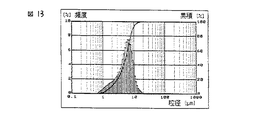
比較例2
図13に示す1山分布の低融点ガラス粉末(7)を用いた以外は、実施例1と同様にして、PDPを作製した。隔壁用感光性ペーストの全光線透過率は46%であった。
ガラス粉末(7):
D10;1.2、平均粒子径;4.6、D90;9.1、最大粒子径;18.5μm、
組成、Tg、Ts、熱膨張係数、屈折率はガラス粉末(1)と同様である。
【0148】
作製したPDPの評価結果を表1に示す。隔壁の蛇行、残膜による放電不良から、輝度は140cd/m2に低下し、輝度ムラを生じた。
【0149】
比較例3
低融点ガラス粉末、フィラーとしてそれぞれ以下の粉末を用いた以外は、実施例5と同様に隔壁の作製、評価を行った。隔壁用感光性ペーストの全光線透過率は36%であった。作製したPDPの評価結果を表2に示す。パターン形成時に残膜およびパターンの太りが発生した。また、隔壁頂部の凹凸は12μmとなり、所望の隔壁が得られなかった。
【0150】
<低融点ガラス粉末>
組成(分析値):酸化ビスマス38%、酸化珪素7%、酸化硼素19%、酸化バリウム12%、酸化アルミニウム3%、酸化亜鉛21%。
【0151】
ガラス転移点:476℃、軟化点:525℃、平均屈折率 1.75、平均粒子径:3.5μm、最大粒子径11μm、タップ密度0.5g/cm3、形状 :非球状。
【0152】
<フィラー:高融点ガラス>
組成(分析値):酸化珪素38%,酸化硼素10%,酸化バリウム5.5%,酸化アルミニウム34.5%,酸化亜鉛2.2%,酸化マグネシウム4.8%,酸化カルシウム4.4%、酸化チタン0.6%
ガラス転移点:655℃、軟化点:770℃、平均屈折率:2.6、平均粒子径:3.6μm、最大粒子径:20μm、タップ密度:0.65g/cm3、形状:非球状。
【0153】
上記の低融点ガラス粉末80重量%、フィラー20重量%からなる無機微粉末の粒度分布は図14に示す通り1山分布であった。
【0154】
【表1】

【表2】
【発明の効果】
本発明によれば、感光性ペースト法によってPDPの隔壁を形成する際、残膜、蛇行の生じない、高アスペクト比且つ高精度のパターン加工が可能となり、輝度ムラのないPDPを高い歩留まりで製造することができる。
【図面の簡単な説明】
【図1】本発明のプラズマディスプレイパネルの断面形状を示す簡略図である。
【図2】本発明のガラス粉末の粒度分布の1例を示す粒度分布図である。
【図3】本発明のガラス粉末の粒度分布の1例を示す粒度分布図である。
【図4】本発明のガラス粉末の粒度分布の1例を示す粒度分布図である。
【図5】ガラス粉末(1)の粒度分布図である。
【図6】ガラス粉末(3)の粒度分布図である。
【図7】ガラス粉末(4)の粒度分布図である。
【図8】ガラス粉末(5)の粒度分布図である。
【図9】実施例5に用いた無機微粉末(混合粉末)の粒度分布図である。
【図10】実施例6に用いた無機微粉末(混合粉末)の粒度分布図である。
【図11】実施例7に用いた無機微粉末(混合粉末)の粒度分布を示す。
【図12】ガラス粉末(6)の粒度分布図である。
【図13】ガラス粉末(7)の粒度分布図である。
【図14】比較例3に用いた無機微粉末(混合粉末)の粒度分布図である。
【符号の説明】
1:前面ガラス基板
2:保護膜
3:透明電極
4:放電電極
5:隔壁
6:蛍光体
7:誘電体層
8:書き込み電極
9:背面ガラス基板[0001]
BACKGROUND OF THE INVENTION
The present invention relates to a novel inorganic fine powder, a photosensitive paste using the same, and more specifically, a plasma display panel (hereinafter abbreviated as PDP), a plasma addressed liquid crystal, an electron-emitting device (Field Emission Display (FED), a field emission type). The present invention relates to a photosensitive paste for forming partition walls (also referred to as ribs or spacers) in a display panel such as a display tube or a surface conduction electron-emitting device, and a manufacturing method thereof.
[0002]
[Prior art]
In recent years, circuit materials and displays have been reduced in size and definition, and accordingly, improvement of pattern processing technology is desired. In particular, a technique capable of patterning an inorganic material such as glass with high accuracy and a high aspect ratio is required for forming partition walls that are partitions of each pixel of a plasma display panel.
[0003]
Plasma display panels (PDPs) are capable of high-speed display and are easy to increase in size, and thus have penetrated fields such as OA equipment and public information display devices. Progress in the field of high-definition television is also highly expected.
[0004]
Accompanying such expansion of applications, a fine color PDP having a large number of display cells has attracted attention. The PDP generates plasma discharge between an anode and a cathode electrode facing each other in a discharge space provided between a front glass substrate and a back glass substrate, and emits ultraviolet rays generated from a gas sealed in the discharge space. The display is performed by touching the phosphor provided in the discharge space. An example of the structure of an AC PDP is shown in FIG. The back plate is provided with white or black barrier ribs in order to secure a discharge space, define a distance between electrodes, and prevent erroneous discharge. In the case of the AC type PDP, the partition walls are formed in a stripe shape.
[0005]
In order to increase the definition of the PDP, it is necessary to reduce the size of one pixel. In this case, it is necessary to reduce the pitch and line width of the partition walls. Specifically, when trying to realize a 42-inch high-definition television (1920 × 1035 pixels) and a 23-inch OA monitor (XGA: 1024 × 768 pixels), the partition walls have a pitch of 150 μm, a width of 20 to 40 μm, and a height of 60 to It is necessary to form with about 170 μm. Usually, the barrier ribs are formed by applying and drying an insulating paste made of glass on the rear glass substrate by screen printing, repeating the coating and
[0006]
With the increase in area and resolution of PDPs, it is becoming increasingly technically difficult and costly to produce high aspect ratio and high definition partition walls by using such screen printing methods. .
[0007]
As a method for improving these problems, JP-A-1-296534, JP-A-2-165538, JP-A-5-342992, and JP-A-6-295676 use a photosensitive paste as a partition. A method of forming by photolithography technology has been proposed. However, these methods have a problem that a dense partition wall cannot be obtained after firing because the glass content of the photosensitive insulating paste is small, and the sensitivity and resolution of the photosensitive paste are low. For this reason, in order to obtain a high aspect ratio partition, it was necessary to repeat the steps of screen printing, exposure, and development. However, repeated printing / exposure / development has a limit due to problems in alignment and costs.
[0008]
Japanese Patent Application Laid-Open No. 8-50811 proposes a method of forming a partition wall by a single exposure using a photosensitive glass paste method. However, in this method, when producing a high-definition partition with a pitch of 200 μm or less and a partition line width of 50 μm or less, the exposure margin is narrow and the line width is increased depending on the ratio of the inorganic component and the organic component in the photosensitive paste. In addition, there is a problem that the remaining film, the meandering of the partition wall, and the like occur. The exposure amount margin is a range of an appropriate exposure amount that does not cause thickening of the line width due to excessive exposure amount, remaining film, or meandering of the partition walls due to insufficient exposure amount. When the line width is increased or the remaining film is generated, the discharge space is narrowed and the discharge characteristics are deteriorated, resulting in display unevenness. Further, when the barrier ribs meander, phosphor coating cannot be performed uniformly, color mixing occurs, and the yield deteriorates.
[0009]
[Problems to be solved by the invention]
An object of the present invention is to provide a display in which a pattern with a high aspect ratio and high accuracy is formed without the above-described drawbacks.
[0010]
[Means for Solving the Problems]
The object of the present invention is for photosensitive pastes. Low melting glass fine powder And the Low melting glass fine powder The particle size distribution of has at least two or more peaks Low melting glass fine powder, and Photosensitive pace using it To This is achieved.
[0011]
DETAILED DESCRIPTION OF THE INVENTION
The inorganic fine powder of the present invention is used for a photosensitive paste comprising an inorganic powder and a photosensitive organic component, and the plasma paste is applied to the photosensitive paste, dried, exposed, developed and baked, and then a plasma display panel, a plasma addressed liquid crystal display panel Alternatively, partition walls such as electron-emitting devices can be formed. The obtained partition wall is a sintered body of inorganic fine powder.
[0012]
The barrier ribs to be formed with the photosensitive paste have a height of 60 to 170 μm, and the thickness of the coating film of the photosensitive paste applied for the barrier rib pattern formation needs to be 100 to 220 μm in consideration of firing shrinkage. It becomes.
[0013]
In order to expose a high-definition pattern on the photosensitive paste coating film having such a thickness and to form a pattern with a high aspect ratio with high resolution, it is necessary to transmit as much actinic light for exposure as possible to the bottom of the coating film. Is essential. Specifically, the photosensitive paste preferably has a total light transmittance of 50% or more measured with a 50 μm-thick coating film. In this case, it is accurate to confirm the effect that the measurement wavelength is measured by the wavelength of light to be exposed after applying the paste.
[0014]
For this reason, the inorganic fine powder and the photosensitive organic component to be blended in the photosensitive paste are both highly light-transmitting, and they are uniformly mixed so that there is no compositional variation such as bubbles inside the paste. Required. However, even if these are satisfied, it is difficult to obtain a photosensitive paste having a high total light transmittance. If the total light transmittance is low, the actinic light for exposure does not sufficiently transmit to the bottom of the coating film. In addition, a high-definition pattern cannot be formed, a remaining film is formed, or a partition pattern is meandered. When a display is manufactured, luminance decreases or luminance unevenness occurs.
[0015]
As a result of intensive studies in the present invention, when the particle size distribution of the inorganic fine powder is shown by a histogram with the vertical axis representing frequency (%) and the horizontal axis representing particle diameter (μm), the particle size distribution has at least two or more peaks ( By using an inorganic fine powder having a bimodal distribution or more for the photosensitive paste, light scattering in the film is suppressed when the photosensitive paste coating film is formed, the total light transmittance is high, and excellent pattern characteristics. It has been found that a photosensitive paste showing can be obtained. Examples of the particle size distribution of the inorganic fine powder of the present invention are shown in FIGS. The inorganic fine powder of the present invention can be used in various combinations of particle size and frequency at the peak of the particle size distribution peak.
[0016]
The inorganic fine powder of the present invention is produced through chemical synthesis, pulverization, classification, and drying steps such as preparation of a preparation raw material, melting or coprecipitation method, thermal decomposition method, and hydrolysis method. Specific examples of the inorganic fine powder include those composed of low melting glass, those composed of low melting glass powder and high melting glass powder, and composed of 40 to 90% by weight of low melting glass powder and 60 to 10% by weight of filler. Etc. are preferably used.
[0017]
The particle size distribution of the inorganic fine powder of the present invention is controlled in the above pulverization and classification steps. For the pulverization, methods such as a ball mill and a jet mill are used, and classification is performed by dry classification such as sieving and airflow classification (jet mill). The particle size distribution of the obtained inorganic fine powder can be measured by a particle size distribution meter using a laser diffraction scattering method. When the inorganic fine powder consists of multiple types of powders with different refractive indexes, first measure each single powder by laser diffraction scattering method, and then calculate the particle size distribution of the composite powder from the particle size distribution of the single powder and the mixing ratio of the powder. Calculate to find. Moreover, about unknown composite powder, an average refractive index can be measured by the Becke method, and it can measure by a laser diffraction scattering method using this value.
[0018]
In general, the adhesion force of particles depends on the surface area and is therefore proportional to the square of the particle diameter, whereas the weight of the particles depends on the volume and is proportional to the cube of the particle diameter. As a result, the smaller the particle size, the easier it is to aggregate, and it will not be uniformly dispersed in the paste, and when a coating film is formed, voids are likely to be formed, resulting in lower light transmission and desired pattern characteristics. Absent. On the other hand, if the particle size is too large, depending on the firing temperature, irregularities occur at the top of the fired partition walls, and a gap is formed between the front plate and the crosstalk when sealed. Further, there is a problem that inorganic fine particles remain as foreign matter in the discharge space. In the present invention, as a result of intensive studies, in addition to the particle size distribution being at least two peaks, the inorganic fine powder having an average particle size and a maximum particle size in the following ranges are less cohesive, so that the pattern formability is further improved. It has been found that an improved photosensitive paste can be obtained, and that there is no problem of unevenness or foreign matter on the top of the partition after firing, and therefore it is suitable for forming a high-definition partition.
1.0 μm ≦ average particle size ≦ 7 μm
Maximum particle size ≦ 40μm
By setting the average particle diameter (also referred to as D50) to 1.0 μm or more, powder agglomeration can be suppressed and good pattern forming properties can be obtained. By setting it as 7 micrometers or less, the unevenness | corrugation of the partition top part after baking can be suppressed and crosstalk can be suppressed. A more preferable range of the average particle size is 1.5 to 6.5 μm, more preferably 2 to 6 μm, and further preferably 2 to 5 μm.
[0019]
By setting the maximum particle size to 40 μm or less, there is no problem that foreign matter remains in the unevenness of the top of the partition after firing or in the discharge space. The maximum particle size is preferably 7 μm or more. By setting the thickness to 7 μm or more, the filling property is good and the pattern forming property is also good. The maximum particle size is more preferably in the range of 10 to 30 μm in order to suppress powder filling properties and unevenness at the top of the partition wall.
[0020]
Further, when the particle diameters when the volume particle diameter of the inorganic fine powder is cumulatively 10% and 90% are D10 and D90, respectively, if these values are in the following ranges, the cohesiveness is small. An inorganic fine powder with good filling properties can be obtained.
0.5μm ≦ D10 ≦ 2μm
4μm ≦ D90 ≦ 20μm
By setting D10 to 0.5 μm or more, powder aggregation can be suppressed, and scattering due to voids between the aggregated powders can be prevented to obtain a high-definition pattern. By making it 2 μm or less, the yield at the time of classification is kept good, and there are no problems such as crosstalk due to irregularities at the top of the partition after firing. A more preferable range of D10 is 0.7 to 1.5 μm.
[0021]
By setting D90 to 4 μm or more, the filling property is good and the pattern forming property is also good. By setting the thickness to 20 μm or less, there is no problem that foreign matter remains in the irregularities on the top of the partition walls or in the discharge space. A more preferable range of D90 is 6 to 15 μm.
[0022]
Among the inorganic fine powders, the filler having a softening point or melting point equal to or higher than the heating temperature in the baking step remains as it is in the partition walls or on the partition wall surfaces, so that the average particle size and the maximum particle size are preferably smaller. That is, these fillers preferably have an average particle size of 1 to 4 μm and a maximum particle size of 25 μm or less. By using a material having such a particle size distribution, it is possible to satisfy the filling property and dispersibility and to constitute a photosensitive paste having excellent coating property and pattern forming property. By setting the average particle size to 4 μm or less and the maximum particle size to 25 μm or less, unevenness at the top of the partition is suppressed, crosstalk during discharge is prevented, and yield is improved. Moreover, aggregation of a powder is suppressed by making the average particle diameter of a
[0023]
The inorganic fine powder for photosensitive paste has a tap density of 0.6 g / cm. Three Or more, preferably 0.65 g / cm Three As described above, the filling property is good, the pattern forming property of the paste is improved, and a high-definition partition can be formed. The tap density is the mass per unit volume of the powder in the vibrated container as described in JIS Z 2500 (2045).
[0024]
The tap density is related to the particle size distribution related to the true specific gravity of the material derived from the low melting point glass and the composition / component selected as the filler and the packing property of the powder itself. Tap density 0.6g / cm Three By setting it as the above, the filling property and dispersibility of the inorganic fine powder at the time of paste preparation become favorable, and the paste excellent in applicability | paintability is obtained.
[0025]
The photosensitive paste of the present invention is composed of an inorganic fine powder composed of a low melting glass powder and a high melting glass powder or filler having various characteristics described so far and a photosensitive organic component.
[0026]
Since the low melting glass powder used in the present invention forms a pattern on a glass substrate having a low glass transition point and a low softening point, a glass material having a glass transition temperature of 400 to 550 ° C. and a softening point of 450 to 600 ° C. should be used. preferable. By setting the glass transition point to 550 ° C. or lower and the softening point to 600 ° C. or lower, baking can be performed below the glass transition point of the glass substrate. Further, the low melting point glass powder is melted and sintered at a lower temperature to reduce the energy consumption in the firing process and reduce the tact time, which is effective for cost reduction. By setting the glass transition point to 400 ° C or higher and the softening point to 450 ° C or higher, the glass does not melt before the photosensitive organic components in the photosensitive paste decompose and vaporize. Will not cause false discharge. More preferably, the glass transition point is in the range of 400 to 500 ° C, and the softening point is in the range of 450 to 550 ° C.
[0027]
The average refractive index of the inorganic fine powder used for the photosensitive paste is 1.5 to 1.8, more preferably 1.5 to 1.7, and still more preferably 1.5 to 1.65. This is appropriate because the transmittance of actinic rays is improved. Here, the average refractive index is a value obtained by measuring the inorganic fine powder uniformly mixed and dispersed by the Becke method. Since the refractive index of most compounds that can be used as the photosensitive organic component that is an essential component of the photosensitive paste is in the range of 1.45 to 1.75, the inorganic fine powder has an average refractive index in the above range. By having it, the average refractive index of each of the inorganic fine powder and the photosensitive organic component is matched within a range of ± 0.05, light scattering in the paste can be suppressed, and actinic light transmittance can be improved. Therefore, it is possible to form a high-definition partition pattern by reducing the number of times of coating and exposure.
[0028]
In order to obtain an inorganic fine powder having an average refractive index of 1.5 to 1.8 that can be baked on a glass substrate, at least one of alkali metal oxides such as sodium oxide, lithium oxide, and potassium oxide is used. It is preferable to use a low-melting glass powder containing 2 to 20% by weight. Thereby, not only the softening point and the thermal expansion coefficient can be easily controlled, but also the average refractive index of the glass can be lowered, so that the difference in refractive index from the organic substance can be easily reduced. By setting it to 2% or more, it becomes easy to control the heat softening temperature. By setting it to 20% or less, it is possible to prevent a decrease in luminance due to evaporation of the alkali metal oxide during discharge. Furthermore, the addition amount of the alkali metal oxide is more preferably 15% by weight or less from the viewpoint of improving the stability of the paste.
[0029]
In addition, by adding aluminum oxide, barium oxide, calcium oxide, magnesium oxide, zinc oxide, zirconium oxide, etc., especially aluminum oxide, barium oxide, zinc oxide, etc., it is possible to improve hardness and workability. However, from the viewpoint of control of the thermal softening point, thermal expansion coefficient, and refractive index, the content is preferably 40% by weight or less.
[0030]
As a glass composition containing lithium oxide,
Lithium oxide: 3 to 15% by weight
Silicon oxide: 15-50% by weight
Boron oxide: 15-40% by weight
Barium oxide: 2 to 15% by weight
Aluminum oxide: 6-25% by weight
It is preferable that
[0031]
When 3 to 15% by weight of lithium oxide is blended, not only the softening point and thermal expansion coefficient of the glass powder can be easily controlled, but also the average refractive index of the glass can be lowered. The ability to lower the average refractive index of glass is an important condition because it is easy to reduce the difference in refractive index from the organic component. Further, from the viewpoint of improving the stability of the photosensitive paste, lithium oxide is preferably 15% by weight or less, more preferably 10% by weight or less, and still more preferably 8% by weight or less.
[0032]
When silicon oxide is blended in an amount of 15 to 50% by weight, the density, strength and stability of the glass layer and the thermal expansion coefficient are set to desired values, the softening point is lowered, and baking onto the substrate is facilitated. This is preferable.
[0033]
Boron oxide is preferably blended in an amount of 15 to 40% by weight in terms of glass stability and insulating layer strength. Boron oxide melts glass powder at a temperature of about 800 to 1200 ° C., so that even when there is more silicon oxide, it has electrical, mechanical and thermal characteristics such as electrical insulation, strength, thermal expansion coefficient, and denseness of the insulating layer. It is preferable to blend in order to control the baking temperature in the range of 520 to 580 ° C. so as not to damage it.
[0034]
Mixing 2 to 15% by weight of barium oxide is preferable in terms of controlling the baking temperature and electrical insulation, and stability and denseness of the glass layer.
[0035]
It is preferable that 6 to 25% by weight of aluminum oxide is blended in that the strength of the glass, the heat resistant temperature of the glass, and a dense insulating layer can be easily obtained. Aluminum oxide can increase the strain point of the glass.
[0036]
The low-melting glass powder is preferably a mixture of calcium oxide and magnesium oxide in addition to the metal oxide.
[0037]
It is preferable that calcium oxide is blended in the range of 2 to 10% by weight in order to keep the strain point moderately. Calcium oxide can easily melt the low-melting glass powder and can control the thermal expansion coefficient.
[0038]
Magnesium oxide is preferably blended in the range of 1 to 10% by weight. Magnesium oxide is added to facilitate melting of the low-melting glass powder and to control the thermal expansion coefficient. If it exceeds 10% by weight, the glass tends to devitrify.
[0039]
Furthermore, although titanium oxide, zirconium oxide, etc. may be mix | blended with glass powder, it is preferable that the quantity is 2 weight% or less. In particular, zirconium oxide is effective in controlling the softening point, glass transition point, and electrical insulation.
[0040]
In the above composition, sodium oxide or potassium oxide may be used instead of lithium oxide, but lithium oxide is preferable in terms of paste stability.
[0041]
The amount of the inorganic fine powder used in the photosensitive paste method is preferably 65 to 90% by weight based on the sum of the inorganic fine powder and the photosensitive organic component. By setting it as 65 weight% or more, shrinkage | contraction at the time of baking can be suppressed and the disconnection and peeling of a partition can be prevented. Also, pattern thickening and residual film formation during development are unlikely to occur. By setting it to 90% by weight or less, the photosensitive component becomes a sufficient amount and the pattern formability is improved. In order to reduce the firing shrinkage, a more preferable amount of the inorganic fine powder is 70 to 80% by weight. Since the inorganic fine powder of the present invention has a high filling property, this amount can be achieved.
[0042]
As the inorganic fine powder constituting the photosensitive paste of the present invention, a filler is preferably used together with a low melting point glass. A filler that is a powder that does not melt at the softening point of the low-melting glass is used. Thereby, volume shrinkage of the partition wall pattern is suppressed and shape retention is improved. The blending ratio of the filler is preferably 10 to 60% by weight with respect to the inorganic fine powder. By making it 10% by weight or more, the effect of suppressing volume shrinkage and maintaining the shape can be obtained, and by making it 60% by weight or less, the adhesion strength on the glass substrate can be maintained and baking can be easily performed. The blending ratio is more preferably 20 to 40% by weight.
[0043]
The filler is ceramics and / or refractory glass powder. The ceramic powder is preferably selected from the group of alumina, zirconia, cordierite, mullite, spinel, titania and silica. These ceramics are components having a high melting point and, like the high melting point glass powder, are not thermally changed at the temperature of the partition pattern firing step, and are dispersed in the partition and remain in a powder state. Of course, the presence of the filler can be obtained by its presence. Furthermore, when these ceramics having an average refractive index in the range of 1.5 to 1.8 are mixed with a low melting glass powder, an inorganic fine powder having an average refractive index of 1.5 to 1.8 is obtained. Is preferred. Furthermore, it is desirable to select a glass having a refractive index difference within a range of ± 0.05 from the low melting point glass powder in order to improve the actinic ray transmission characteristics. Those having an average refractive index exceeding 1.8, such as titania and zirconia, cause scattering in the photosensitive paste, impedes the transmission of actinic rays and reduces pattern formation, but the formed barrier ribs become white and fluorescent. A small amount can be added in order to exhibit the effect of increasing the luminance of the display by reflecting light emitted from the body layer.
[0044]
As the high melting point glass which is another embodiment of the filler, those having a glass transition point of 570 to 1200 ° C. and a softening point of 620 to 1200 ° C. are preferable. Such a high-melting glass preferably has a composition containing 15% by weight or more of silicon oxide and aluminum oxide, respectively, in order to obtain necessary thermal characteristics that the total content thereof is 50% by weight or more. It is valid. For example, a high melting point glass powder containing the following oxide conversion composition is preferably used, but is not limited thereto.
[0045]
Silicon oxide 15-50% by weight
Boron oxide 5-20% by weight
Aluminum oxide 15-50% by weight
Barium oxide 2-10% by weight
It is also possible to use the refractory glass powder and the ceramics as fillers at the same time.
[0046]
The photosensitive organic component forms a pattern by utilizing a change caused by a photoreaction caused by absorbing light energy used for exposure. For photosensitive organic components, a light-dissolving type (positive type) in which the light-affected part dissolves in the solvent and a light-insoluble type (negative type) in which the light-acting part is insoluble in the solvent Is known, and any photosensitive component used in the photosensitive paste may be used.
[0047]
As a photosensitive organic component that is a constituent component of the photosensitive paste, it contains a photosensitive component selected from at least one of a photosensitive monomer, a photosensitive oligomer, and a photosensitive polymer, and if necessary, photopolymerization is started. Photosensitivity is imparted by adding additive components such as an agent, an ultraviolet absorber, a sensitizer, a sensitization aid, and a polymerization inhibitor. In this case, the paste can be applied onto a glass substrate, dried, and then subjected to pattern exposure to develop and remove unnecessary uncured portions, leaving a cured portion to form a pattern.
[0048]
As a light-insoluble photosensitive component,
(A) containing a functional monomer, oligomer or polymer having one or more unsaturated groups in the molecule
(B) Containing photosensitive compounds such as aromatic diazo compounds, aromatic azide compounds, and organic halogen compounds
(C) There are so-called diazo resins such as a condensate of diazo amine and formaldehyde.
[0049]
In addition, as a light-soluble type,
(D) Containing inorganic salts of diazo compounds and organic acids, quinonediazos
(E) For example, naphthoquinone-1,2-diazide-5-sulfonic acid ester of phenol, novolak resin, or the like in which quinonediazos are bonded to a suitable polymer binder.
[0050]
As the photosensitive component used in the present invention, all of the above can be used. The photosensitive paste (A) is preferable in that it can be used simply by mixing with inorganic fine powder.
[0051]
The photosensitive monomer is a compound containing a carbon-carbon unsaturated bond, and specific examples thereof include methyl acrylate, ethyl acrylate, n-propyl acrylate, isopropyl acrylate, n-butyl acrylate, sec-butyl acrylate, isobutyl. Acrylate, tert-butyl acrylate, n-pentyl acrylate, allyl acrylate, benzyl acrylate, butoxyethyl acrylate, butoxytriethylene glycol acrylate, cyclohexyl acrylate, dicyclopentanyl acrylate, dicyclopentenyl acrylate, 2-ethylhexyl acrylate, glycerol acrylate, Glycidyl acrylate, heptadecafluorodecyl acrylate, 2-hydroxyethyl acrylate Isobornyl acrylate, 2-hydroxypropyl acrylate, isodecyl acrylate, isooctyl acrylate, lauryl acrylate, 2-methoxyethyl acrylate, methoxyethylene glycol acrylate, methoxydiethylene glycol acrylate, octafluoropentyl acrylate, phenoxyethyl acrylate, stearyl acrylate, trifluoro Ethyl acrylate, allylated cyclohexyl diacrylate, 1,4-butanediol diacrylate, 1,3-butylene glycol diacrylate, ethylene glycol diacrylate, diethylene glycol diacrylate, triethylene glycol diacrylate, polyethylene glycol diacrylate, dipentaerythritol Hexaacryle Dipentaerythritol monohydroxypentaacrylate, ditrimethylolpropane tetraacrylate, glycerol diacrylate, methoxylated cyclohexyl diacrylate, neopentyl glycol diacrylate, propylene glycol diacrylate, polypropylene glycol diacrylate, triglycerol diacrylate, trimethylolpropane Triacrylate, acrylamide, aminoethyl acrylate, phenyl acrylate, phenoxyethyl acrylate, benzyl acrylate, 1-naphthyl acrylate, 2-naphthyl acrylate, bisphenol A diacrylate, diacrylate of bisphenol A-ethylene oxide adduct, bisphenol A-propylene oxide Additive di Acrylates such as acrylates, thiophenol acrylates, benzyl mercaptan acrylates, monomers having 1 to 5 of these aromatic ring hydrogen atoms substituted with chlorine or bromine atoms, or styrene, p-methylstyrene, o- Methyl styrene, m-methyl styrene, chlorinated styrene, brominated styrene, α-methyl styrene, chlorinated α-methyl styrene, brominated α-methyl styrene, chloromethyl styrene, hydroxymethyl styrene, carboxymethyl styrene, vinyl naphthalene, Examples include vinyl anthracene, vinyl carbazole, and those in which some or all of the acrylates in the molecule of the above compound are replaced with methacrylate, γ-methacryloxypropyltrimethoxysilane, 1-vinyl-2-pyrrolidone, and the like. That. In the present invention, one or more of these can be used.
[0052]
In addition to these, the development property after exposure can be improved by adding an unsaturated acid such as an unsaturated carboxylic acid. Specific examples of the unsaturated carboxylic acid include acrylic acid, methacrylic acid, itaconic acid, crotonic acid, maleic acid, fumaric acid, vinyl acetic acid, and acid anhydrides thereof.
[0053]
The content of these monomers is preferably 5 to 30% by weight with respect to the sum of the glass powder and the photosensitive component. By setting it within this range, the pattern formability becomes good, and the hardness after curing is sufficient.
[0054]
Moreover, the oligomer and polymer obtained by superposing | polymerizing at least 1 type among the compounds which have the above-mentioned carbon-carbon double bond can be used. In the polymerization, it can be copolymerized with other photosensitive monomers so that the content of these photoreactive monomers is 10% by weight or more, more preferably 35% by weight or more.
[0055]
As a monomer to be copolymerized, the developability after exposure can be improved by copolymerizing an unsaturated acid such as an unsaturated carboxylic acid. Specific examples of the unsaturated carboxylic acid include acrylic acid, methacrylic acid, itaconic acid, crotonic acid, maleic acid, fumaric acid, vinyl acetic acid, and acid anhydrides thereof.
[0056]
The acid value (AV) of the polymer or oligomer having an acidic group such as a carboxyl group in the side chain thus obtained is preferably 50 to 180, more preferably 70 to 140. When the acid value is less than 50, the allowable development width becomes narrow. Further, if the acid value exceeds 180, the solubility of the unexposed portion in the developing solution is lowered. Therefore, if the concentration of the developing solution is increased, the exposed portion is peeled off and it is difficult to obtain a high-definition pattern.
[0057]
By adding a photoreactive group to the side chain or molecular end of the polymer or oligomer shown above, it can be used as a photosensitive polymer or photosensitive oligomer having photosensitivity. Preferred photoreactive groups are those having an ethylenically unsaturated group. Examples of the ethylenically unsaturated group include a vinyl group, an allyl group, an acrylic group, and a methacryl group.
[0058]
Such a side chain can be added to an oligomer or polymer by using an ethylenically unsaturated compound having a glycidyl group or an isocyanate group relative to a mercapto group, amino group, hydroxyl group or carboxyl group in the polymer. There is a method of making an acid chloride or allyl chloride by addition reaction.
[0059]
Examples of the ethylenically unsaturated compound having a glycidyl group include glycidyl acrylate, glycidyl methacrylate, allyl glycidyl ether, glycidyl ethyl acrylate, crotonyl glycidyl ether, glycidyl crotonic acid, glycidyl ether of isocrotonic acid, and the like.
[0060]
Examples of the ethylenically unsaturated compound having an isocyanate group include (meth) acryloyl isocyanate and (meth) acryloylethyl isocyanate.
[0061]
In addition, the ethylenically unsaturated compound having a glycidyl group or an isocyanate group, acrylic acid chloride, methacrylic acid chloride or allyl chloride is 0.05 to 1 molar equivalent with respect to a mercapto group, amino group, hydroxyl group or carboxyl group in the polymer. It is preferable to add.
[0062]
The amount of the polymer component consisting of the photosensitive polymer, photosensitive oligomer and binder in the photosensitive paste is excellent in terms of pattern formability and shrinkage after firing, so it is the sum of glass powder and photosensitive component. On the other hand, it is preferably 5 to 30% by weight. Outside this range, pattern formation tends to be impossible or the pattern will become thicker.
[0063]
There are different types of photopolymerization initiators such as a single molecule direct cleavage type, an ion-pair electron transfer type, a hydrogen abstraction type, and a two-molecule complex system, which can be selected and used in the present invention. Is preferably a compound selected from a single-molecule direct cleavage type. Examples include benzoin alkyl ethers, α, α-dimethoxy-α-morpholinoacetone phenone, α, α-dimethoxy-α-phenylacetone phenone, and the like. Further, peroxides, phosphine oxides, sulfur compounds, halogen compounds and the like may be used, and these may be used alone or in combination.
[0064]
Also, benzophenone, methyl o-benzoylbenzoate, 4,4-bis (dimethylamino) benzophenone, 4,4-bis (diethylamino) benzophenone, 4,4-dichlorobenzophenone, 4-benzoyl-4-methyldiphenyl ketone, di Benzyl ketone, fluorenone, 2,2-diethoxyacetophenone, 2,2-dimethoxy-2-phenyl-2-phenylacetophenone, 2-hydroxy-2-methylpropiophenone, pt-butyldichloroacetophenone, thioxanthone, 2 -Methylthioxanthone, 2-chlorothioxanthone, 2-isopropylthioxanthone, diethylthioxanthone, benzyldimethylketanol, benzylmethoxyethyl acetal, 2-benzyl-2-dimethylamino-1- (4-morph Linophenyl) -butanone-1, benzoin, benzoin methyl ether, benzoin butyl ether, anthraquinone, 2-t-butylanthraquinone, 2-amylanthraquinone, β-chloroanthraquinone, anthrone, benzanthrone, dibenzosuberone, methyleneanthrone, 4-azido Benzalacetophenone, 2,6-bis (p-azidobenzylidene) cyclohexanone, 2,6-bis (p-azidobenzylidene) -4-methylcyclohexanone, 2-phenyl-1,2-butadion-2- (o-methoxy) Carbonyl) oxime, 1-phenyl-propanedione-2- (o-ethoxycarbonyl) oxime, 1,3-diphenyl-propanetrione-2- (o-ethoxycarbonyl) oxime, 1-phenyl-3-ethoxy -Propanetrione-2- (o-benzoyl) oxime, Michler's ketone, 2-methyl- [4- (methylthio) phenyl] -2-morpholino-1-propanone, naphthalenesulfonyl chloride, quinolinesulfonyl chloride, N-phenylthioacridone , 4,4-azobisisobutyronitrile, diphenyl disulfide, benzthiazole disulfide, triphenylphosphine, camphorquinone, carbon tetrabromide, tribromophenylsulfone, benzoin peroxide and eosin, methylene blue And a combination of reducing agents such as ascorbic acid and triethanolamine. In the present invention, one or more of these can be used.
[0065]
The photopolymerization initiator is generally added in an amount of 0.05 to 20% by weight, more preferably 1 to 15% by weight, based on the photosensitive component. If the amount of the polymerization initiator is too small, the photosensitivity will be poor, and if the amount of the photopolymerization initiator is too large, the residual ratio of the exposed area may be too small.
[0066]
By blending a sensitizer with a photopolymerization initiator, sensitivity can be improved (chemical sensitization), and the wavelength range effective for the reaction can be expanded (spectral sensitization).
[0067]
There are various mechanisms of action of sensitizers, but what is called a triplet sensitizer is most often used. Among these are hydrocarbon compounds, amino / nitro compounds, quinones, xanthones, anthrones, ketones, and organic dyes. Some of these have a function as a photopolymerization initiator.
[0068]
In the present invention, the sensitizer used in combination with the single-molecule direct-cleavage photopolymerization initiator is preferably a compound selected from xanthones, and specifically includes 2,4-diethylthioxanthone and isopropylthioxanthone. . These can be used alone or in combination of two or more.
[0069]
If there are too few photopolymerization initiators and sensitizers, sufficient sensitivity cannot be obtained, but it is possible to increase the sensitivity by increasing the amount, but the degree of polymerization of the cured part is not sufficiently high, and exposure is not possible. There is a possibility that the residual ratio of the portion may be reduced, and there is a disadvantage that unnecessary curing occurs between the patterns and a remaining film is formed. It is important to use a proper amount of a photopolymerization initiator and a sensitizer in order to form a pattern having an appropriate shape with moderate sensitivity.
[0070]
Mixing an ultraviolet absorber with the photosensitive paste of the present invention is effective for processing a pattern having an excellent shape.
[0071]
As the ultraviolet absorber, an organic dye, particularly an organic dye having a high UV absorption coefficient in a wavelength range of 350 to 450 nm is preferably used. Specifically, azo dyes, amino ketone dyes, xanthene dyes, quinoline dyes, amino ketone dyes, anthraquinone dyes, benzophenone dyes, cyanoacrylate dyes, benzotriazole compounds, indole compounds, diphenyl cyanoacrylate dyes, triazines And p-aminobenzoic acid dyes can be used. Even when an organic dye is added as a light-absorbing agent, it is preferable because it does not remain in the insulating film after baking and the deterioration of the insulating film characteristics due to the light-absorbing agent can be reduced. Of these, azo dyes and benzophenone dyes are preferable.
[0072]
Specific examples include Sudan IV (Solvent Red 24), 4-dihydroxybenzophenone, 2-hydroxy-4-methoxybenzophenone, 2,2′-dihydroxy-4-methoxybenzophenone, 2,2′-dihydroxy-4,4′-. Dimethoxybenzophenone, 2,2′-dihydroxy-4,4′-dimethoxy-5-sulfobenzophenone, 2-hydroxy-4-methoxy-2′-carboxybenzophenone, 2-hydroxy-4-methoxy-5-sulfobenzophenone trihydride 2-hydroxy-4-n-octoxybenzophenone, 2-hydroxy-4-octadecyloxybenzophenone, 2,2 ′, 4,4′-tetrahydroxybenzophenone, 4-dodecyloxy-2-hydroxybenzophenone, 2- Hydroxy-4- (2-hydroxy -3-methacryloxy) propoxybenzophenone, 2- (2′-hydroxy-5′-methylphenyl) benzotriazole, 2- (2′-hydroxy-3 ′, 5′-di-t-butylphenyl) benzotriazole, 2 -(2'-hydroxy-3'-tert-butyl-5'-methylphenyl) -5-chlorobenzotriazole, 2- (2'-hydroxy-3 ', 5'-di-tert-butylphenyl) -5 -Chlorobenzotriazole, 2- (2'-hydroxy-4'-n-octoxyphenyl) benzotriazole, 2-ethylhexyl-2-cyano-3,3-diphenyl acrylate, 2-ethyl-2-cyano-3, 3-diphenyl acrylate, BONASORB UV-3901 (manufactured by Orient Chemical Co., Ltd.), BONASORB UA-3902 (manufactured by Orient Chemical Co., Ltd.) And the like SOM-2-0008 (manufactured by Orient Chemical Co.), but it is not limited thereto. In the present invention, one or more of these can be used. Furthermore, a methacryl group or the like may be introduced into the skeleton of these ultraviolet absorbers and used as a reaction type.
[0073]
The addition amount of the organic dye is preferably 0.05 to 1 part by weight with respect to the inorganic fine powder.
[0074]
Outside these ranges, there is a tendency that the absorption capacity of h-line and i-line is insufficient, the transmittance of g-line is lowered, and the sensitivity of the photosensitive paste is lowered. If it is 0.05% by weight or less, the effect of adding the ultraviolet light absorber is reduced, and if it exceeds 1% by weight, the insulating film characteristics after firing tend to be lowered. More preferably, it is 0.05 to 0.2% by weight. Furthermore, the photosensitive paste of the present invention preferably contains a polymerization inhibitor in order to maintain good pattern forming properties.
[0075]
An example of a method for adding an ultraviolet light absorber composed of an organic dye is to prepare a solution in which an organic dye is previously dissolved in an organic solvent, and to add inorganic fine powder in the organic solvent in addition to the method of kneading it at the time of preparing the paste. The method of drying after mixing is mentioned. By this method, so-called capsule-shaped fine particles in which the surface of each glass fine particle is coated with an organic film can be produced.
A sensitizer is added in order to improve sensitivity. Specific examples of the sensitizer include 2,4-diethylthioxanthone, isopropylthioxanthone, 2,3-bis (4-diethylaminobenzal) cyclopentanone, 2,6-bis (4-dimethylaminobenzal) cyclohexanone, 2,6-bis (4-dimethylaminobenzal) -4-methylcyclohexanone, Michler's ketone, 4,4-bis (diethylamino) -benzophenone, 4,4-bis (dimethylamino) chalcone, 4,4-bis (diethylamino) ) Chalcone, p-dimethylaminocinnamylidene indanone, p-dimethylaminobenzylidene indanone, 2- (p-dimethylaminophenylvinylene) -isonaphthothiazole, 1,3-bis (4-dimethylaminobenzal)
[0076]
A polymerization inhibitor is added to improve the thermal stability during storage. The polymerization inhibitor is not particularly limited as long as it can be used as a polymerization inhibitor, and specific examples thereof include p-benzoquinone, naphthoquinone, para-xyloquinone, para-toluquinone, 2,6-dichloroquinone, 2, 5-diacetoxy-p-benzoquinone, 2,5-dicaproxy-p-benzoquinone, 2,5-diaeroxy-p-benzoquinone, hydroquinone, pt-butylcatechol, 2,5-dibutylhydroquinone, mono-t-butylhydroquinone 2,5-di-t-amylhydroquinone, di-t-butyl paracresol, hydroquinone monomethyl ether, α-naphthol, acetanidin acetate, hydrazine hydrochloride, trimethylbenzylammonium chloride, trimethylbenzylammonium oxalate, Phenyl-β-naphthyl Amine, parabenzylaminophenol, di-β-naphthylparaphenylenediamine, dinitrobenzene, trinitrobenzene, picric acid, quinonedioxime, cyclohexanone oxime, pyrogallol, tannic acid, resormine, triethylamine hydrochloride, dimethylaniline hydrochloride, cuperone, etc. Is mentioned. When adding a polymerization inhibitor, the addition amount is 0.01 to 20 weight% normally in the photosensitive paste.
[0077]
The photosensitive paste contains a large amount of inorganic fine powder in a dispersed state, and it is difficult to avoid that the exposed light is scattered inside the paste. (Residual film formation) is likely to occur. It is preferable that the partition wall pattern has vertical side walls and a rectangular cross-sectional shape. Ideally, a portion irradiated with light below a certain exposure amount is dissolved in the developer, and beyond that, it becomes insoluble in the developer. That is, if a portion cured with a low exposure amount such as that caused by scattered light is dissolved in the developer, thickening of the pattern shape and residual film formation are eliminated. However, since the development latitude is unlikely to be such, it is necessary to prevent photocuring with a small exposure amount by adding a polymerization inhibitor. Addition of a polymerization inhibitor to the photosensitive paste deactivates the polymerization by returning the energy state of the photopolymerization initiator or sensitizer excited with a small exposure amount to the ground state or capturing the generated radicals. Therefore, hardening of the part which becomes fat and a remaining film can be suppressed.
[0078]
Such a polymerization inhibitor is not limited as long as it has a radical chain inhibition action, a triplet elimination action, and a hydroperoxide decomposition action, and one or more kinds may be used. The addition amount is preferably 0.01 to 5% by weight, more preferably 0.03 to 3% by weight. If it is less than this range, the effect of inhibiting polymerization is not exhibited, and if it is increased, the sensitivity is lowered.
[0079]
An organic binder, a plasticizer, a solvent, and a dispersant, a leveling agent, and the like can be added to the photosensitive organic component used in the photosensitive paste. Specific examples of the organic binder include polyvinyl alcohol, cellulose polymer, silicon polymer, polyethylene, polyvinyl pyrrolidone, polystyrene, polyamide, high molecular weight polyether, polyvinyl butyral, methacrylic ester polymer, acrylic ester polymer, acrylic Acid ester-methacrylic acid ester copolymer, α-methylstyrene polymer, butyl methacrylate resin, and the like. It is necessary to select a binder that does not dissolve in the partition wall developer. Moreover, when adjusting the viscosity of a paste, it is preferable to use the solvent of a binder component. As the solvent, methyl cellosolve, ethyl cellosolve, butyl cellosolve, methyl ethyl ketone, dioxane, acetone, cyclohexanone, cyclopentanone, isobutyl alcohol, isopropyl alcohol, tetrahydrofuran, dimethyl sulfoxide, γ-butyrolactone, bromobenzene, chlorobenzene, dibromobenzene, dibromo Chlorobenzene, bromobenzoic acid, chlorobenzoic acid, and the like, and organic solvent mixtures containing one or more of these are used. Moreover, a plasticizer can also be included in a paste. Specific examples of the plasticizer include dibutyl phthalate, dioctyl phthalate, polyethylene glycol, glycerin and the like.
[0080]
After mixing each of the above components, a dielectric and partition paste can be prepared by uniformly mixing and dispersing with a kneader such as a three-roller or planetary mixer.
[0081]
Next, the inorganic fine powder of the present invention, a photosensitive paste, and a method for producing a partition using the same will be described. The low-melting-point glass powder and filler powder contained in the paste of the present invention are subjected to chemical synthesis, pulverization, classification and drying processes such as preparation of blended raw materials, melting or coprecipitation method, thermal decomposition method, hydrolysis method and the like. Produced. Classification is performed by dry classification such as sieving and airflow classification. The particle size and distribution of the low-melting glass powder and filler powder are controlled in the above pulverization and classification steps. For the pulverization, a method such as a ball mill or a jet mill is used, and the particle size distribution of the obtained powder can be measured by a laser diffraction / scattering method.
[0082]
Next, although an example of the process of producing PDP using the inorganic fine powder of this invention is demonstrated, this invention is not limited to this.
[0083]
The low-melting glass and the high-melting glass powder of the present invention are produced through respective steps of preparation of raw material for preparation, melting, pulverization, classification and drying. Various methods can be used for pulverization and classification, but the dry method is preferred in view of the stability of the composition of the glass powder. Specifically, a jet crusher such as “SK Jet O Mill” (manufactured by Seishin Enterprise Co., Ltd.) is used for pulverization, and “Spedick Classifier” (manufactured by Seisin Enterprise Co., Ltd.) is used for classification. A dry air classifier such as is preferably used.
[0084]
The inorganic fine powder containing the obtained glass powder and the photosensitive organic component are prepared so as to have a predetermined composition, and then mixed and dispersed homogeneously with a kneader such as a three-roller or a planetary mixer.
[0085]
The viscosity of the paste is appropriately adjusted depending on the addition ratio of inorganic fine powder, thickener, organic solvent, plasticizer, precipitation inhibitor, etc., but the range is 2000 to 200,000 cps (centipoise). For example, when the application to the glass substrate is performed by a spin coating method other than the screen printing method, 200 to 5000 cps is preferable. In order to obtain a film thickness of 10 to 20 μm by applying it once by the screen printing method, 4000 to 200,000 cps is preferable. Here, the viscosity is a value obtained by a rotational viscometer method.
[0086]
A photosensitive paste is applied to a thickness of 100 to 220 μm on a glass substrate on which electrodes and dielectric layers are formed. As a coating method, methods such as screen printing, bar coater, roll coater, die coater, and blade coater can be used. The coating thickness can be adjusted by selecting the number of coatings and the viscosity of the paste.
[0087]
After application of the photosensitive paste, drying is performed to remove the solvent in the paste. After drying, exposure is performed using an exposure apparatus. In general, the exposure is performed by mask exposure using a photomask, as in normal photolithography. As the mask to be used, either a negative type or a positive type is selected depending on the type of the photosensitive organic component. Alternatively, a method of directly drawing with a red or blue laser beam or the like without using a photomask may be used.
[0088]
As the exposure apparatus, a stepper exposure machine, a proximity exposure machine or the like can be used. Moreover, when performing exposure of a large area, a large area can be exposed with an exposure machine having a small exposure area by applying a photosensitive paste on a substrate such as a glass substrate and then performing exposure while transporting. it can.
[0089]
Examples of the active light source used at this time include visible light, near ultraviolet light, ultraviolet light, electron beam, X-ray, and laser light. Among these, ultraviolet light is preferable. Mercury lamps, ultra-high pressure mercury lamps, halogen lamps, germicidal lamps, etc. can be used. Among these, an ultrahigh pressure mercury lamp is suitable. Although exposure conditions vary depending on the coating thickness, exposure is performed for 10 seconds to 30 minutes using an ultrahigh pressure mercury lamp having an output of 1 to 50 mW / cm 2.
[0090]
After exposure, development is performed using the difference in solubility between the photosensitive part and the non-photosensitive part in the developer. In this case, the immersion method, the shower method, the spray method, and the brush method are used.
[0091]
As the developer to be used, an organic solvent in which an organic component in the photosensitive paste can be dissolved can be used. Further, water may be added to the organic solvent as long as its dissolving power is not lost. When a compound having an acidic group such as a carboxyl group is present in the photosensitive paste, development can be performed with an aqueous alkaline solution. A metal alkali aqueous solution such as sodium hydroxide, sodium carbonate, calcium hydroxide aqueous solution or the like can be used as the alkali aqueous solution. However, it is preferable to use an organic alkali aqueous solution because an alkaline component can be easily removed during firing.
[0092]
As the organic alkali, an amine compound can be used. Specific examples include tetramethylammonium hydroxide, trimethylbenzylammonium hydroxide, monoethanolamine, and diethanolamine. The concentration of the alkaline aqueous solution is usually 0.05 to 3% by weight, more preferably 0.1 to 1% by weight. If the alkali concentration is too low, the soluble portion is not removed, and if the alkali concentration is too high, the pattern portion may be peeled off and the non-soluble portion may be corroded. The development temperature during development is preferably 20 to 50 ° C. in terms of process control.
[0093]
The barrier rib pattern formed through the exposure / development process from the photosensitive paste coating film is then baked in a baking furnace. The firing atmosphere and temperature vary depending on the type of paste and substrate, but are usually fired in air. As the firing furnace, a batch-type firing furnace or a belt-type continuous firing furnace can be used. In the case of batch-type firing, the glass substrate on which the barrier rib pattern is formed is heated from room temperature to about 500 ° C. over several hours at a substantially constant speed, and further from 520 to 590 ° C. set as the firing temperature to 30 to 30 ° C. Raise in 40 minutes and hold for 15-30 minutes to fire. These conditions are general, and when the thermal characteristics of the low melting point glass component change, it is necessary to set new conditions. The firing temperature is set to a temperature lower than the glass transition point of the glass substrate to be used.
[0094]
Moreover, you may introduce | transduce a 50-300 degreeC heating process for the purpose of drying and a preliminary reaction in each process of the above application | coating, exposure, image development, and baking.
[0095]
Next, a PDP back plate capable of full-color display can be produced by pattern-printing phosphor pastes that emit light in red, blue, and green colors by screen printing.
[0096]
Next, the photosensitive paste of this invention and the evaluation method of a partition using the same are demonstrated.
[0097]
As a method for determining the quality of the photosensitive paste, there is a light transmittance measurement. Specifically, it is preferable that the total light transmittance measured by a 50 μm-thick coating film obtained by drying after coating by the above method is 50% or more. In this case, it is accurate to confirm the effect that the measurement wavelength is measured by the wavelength of light to be exposed after applying the paste.
[0098]
The quality of the pattern formation of the photosensitive paste is judged by various requirements. In the present invention, the standard of the excellent pattern formation is the exposure conditions in the exposure / development, which is the pattern formation process in the photolithography method. The size of the margin. Usually, in pattern exposure through a photomask, the line width at the central point of the height of the formed partition wall is measured, and even if the exposure amount changes by ± 10%, the line width changes only slightly. The case where no pattern formation occurred was defined as having excellent pattern formability.
[0099]
Furthermore, as a method of judging the quality of the produced partition wall, there are a top unevenness measurement and a firing shrinkage rate measurement. The top unevenness is measured using a surface shape measuring microscope (manufactured by Keyence Co., Ltd.) using optical interference or a stylus type surface roughness meter (Surfcom 1500A, manufactured by Tokyo Seimitsu Co., Ltd.), and parallel to the stripes of the partition walls. Is represented by RMAX when measured at a measurement length of about 0.2 mm. It is desirable that RMAX is 10 μm or less, preferably 5 μm or less. The firing shrinkage ratio is calculated by the following formula from the partition wall height before firing and the partition wall height after firing.
(1-height after firing / height before firing) × 100 (%)
The height of the partition wall is measured by photographing the cross section of the partition wall with a scanning electron microscope or using the surface shape measuring microscope. The firing shrinkage rate is 30% or less, preferably 25% or less, more preferably 20% or less, which is effective for maintaining an excellent partition wall shape and suppressing height variation due to firing temperature variation.
[0100]
【Example】
Hereinafter, the present invention will be specifically described with reference to examples. However, the present invention is not limited to this. The concentration (%) in Examples and Comparative Examples is% by weight unless otherwise specified.
[0101]
(Measuring method)
(1) Particle size distribution
Nikkiso Co., Ltd. (Microtrac HRA particle size analyzer MODEL No. 9320-X100)
Measurement conditions were as follows.
Sample amount: 0.5g
Dispersion conditions: Ultrasonic dispersion in purified water for 1 to 1.5 minutes.
Particle refractive index: Varies depending on the type of inorganic powder (1.6 for lithium glass powder and 1.88 for bismuth glass powder)
Solvent refractive index: 1.33
Number of measurements: 2 times
[0102]
When the inorganic fine powder was composed of a plurality of types of powders having the same refractive index, each powder was mixed and then measured by the above method. In addition, when the inorganic fine powder consists of multiple types of powders with different refractive indexes, each single powder is first measured by the laser diffraction scattering method, and then the particle size distribution of the composite powder is determined from the particle size distribution of the single powder and the mixing ratio of the powder. Was calculated.
[0103]
(2) Tap density
Using a TSUTSUI SCIENTIFIC INSTRUMENTS CO. ABD POWDER TESTER, a 100 cc container containing the powder was vibrated for 5 minutes, then the powder was scraped off and the powder mass per 100 cc was measured.
[0104]
(3) Viscosity
Measurement was performed using a digital rotary viscometer manufactured by Brookfield, USA.
[0105]
(4) Light transmittance
It measured using the spectrophotometer (UV-3101PC) by Shimadzu Corporation.
[0106]
(5) Brightness
The entire surface of the plasma display panel was turned on, and measurement was performed using a side light machine MCPD-200 manufactured by Otsuka Electronics.
[0107]
(6) Bulkhead pattern evaluation
The partition wall cross-sectional shape was observed using a scanning electron microscope, the height was measured, and the shape was evaluated. The case where there was a defect such as meandering or a residual film, or the line width of the partition pattern did not fall within the range of 33 to 48 μm (corresponding to 25 to 35 μm after firing) was evaluated as x. Further, the case where the change in the line width of the barrier rib pattern when the exposure amount was changed by ± 10% with respect to 400 mJ / cm 2 exceeded ± 5 μm was also evaluated as x. For observation, samples were taken from nine points on one substrate. Moreover, the unevenness | corrugation measurement of a partition top part was performed using the surface shape measurement microscope (made by Keyence Corporation).
[0108]
Example 1
<Low melting glass powder>
A two-distributed glass powder (1) shown in FIG. 5 was prepared through the steps of preparation, melting, pulverization, classification and drying of the blended raw materials. “SK Jet Oh Mill” (Seishin Enterprise Co., Ltd.) is used for grinding, “Spedick Classifier” (Seishin Enterprise Co., Ltd.) is used for classification, and airflow dryer (Seishin Enterprise Co., Ltd.) is used for drying. Using.
Glass powder (1):
D10: 0.9 μm, average particle size: 2.2 μm, D90: 7.0 μm, maximum particle size: 22.0 μm,
Composition; Li 2 O 7%, Na 2 O 2%, SiO 2 21%, B 2 O Three 31%,
[0109]
<Preparation of organic components>
The following solvent and polymer were mixed to form a 40% solution and heated to 60 ° C. with stirring to dissolve all the polymers homogeneously to obtain a polymer solution.
[0110]
Solvent: gamma butyrolactone (γ-BL)
Polymer: 0.4 equivalent of glycidyl methacrylate (GMA) with respect to the carboxyl group of a copolymer consisting of 40% methacrylic acid (MAA), 30% methyl methacrylate (MMA) and 30% styrene (St) ) Is a photopolymer having a weight average molecular weight of 43,000 and an acid value of 95.
[0111]
Next, each of the organic components shown below was added to and dissolved in 400 g of the above polymer solution cooled to room temperature, and then the solution was filtered using a 400 mesh filter to prepare an organic vehicle.
[0112]
Organic dye: Sudan IV: Azo-based organic dye (Chemical formula C twenty four H 20 N Four O) 0.5g
Monomer: TMPTA: Trimethylolpropane triacrylate 150 g
Initiator: “Irgacure” 369 25 g, manufactured by Ciba Geigy
Sensitizer: 2,4-diethylthioxanthone 25g
Sensitization aid: p-dimethylaminobenzoic acid ethyl ester 10 g
Plasticizer: Dibutyl phthalate (DBP) 20g
Solvent: 80 g of γ-BL
60 g of the above glass powder (1) was added to 40 g of the obtained organic vehicle, kneaded and then uniformly dispersed with three rollers to produce a photosensitive paste for partition walls.
[0113]
The obtained light-sensitive paste was applied to a soda glass substrate having a thickness of 1.3 mm in a thickness of 50 μm and dried to obtain a film having a total light transmittance of 63%.
[0114]
Next, a glass substrate (PD-200 manufactured by Asahi Glass Co., Ltd.) having a size of 240 × 300 mm (A4 size) was used as the glass substrate for the back plate. A striped electrode having a pitch of 150 μm, a line width of 40 μm, and a fired thickness of 6 μm was formed on the glass substrate by photolithography using a photosensitive silver paste as a writing electrode.
[0115]
Next, a dielectric layer paste comprising the following components was prepared.
Glass powder (2): 50% by weight
D10: 1.1 μm, average particle size: 2.5 μm, D90: 4.1 μm, maximum particle size: 6.5 μm
Composition Bi 2 O Three 38%,
White pigment: TiO 2 (Ishihara Sangyo Co., Ltd .: TR-50) 5% by weight
Solvent: 20% by weight of terpineol
Polymer: 20% by weight of ethyl cellulose
Thixotropic agent: 15% SiO 2 2- (2-Butoxyethoxy) ethyl acetate solution
5% by weight
[0116]
The solvent and the polymer were mixed and heated to 60 ° C. with stirring to uniformly dissolve all the polymers to obtain a polymer solution. A glass layer (2), a white pigment, and a thixotropic agent were mixed into this polymer solution, and then dispersed uniformly with three rollers to produce a dielectric layer paste. This was applied and dried by screen printing using a 325 mesh screen, and after drying, a uniform film having a thickness of 20 μm was obtained. The coating thickness was adjusted by the squeegee angle and speed. The dielectric paste coating film thus obtained was baked in air at 580 ° C. for 30 minutes to form a dielectric layer having a thickness of 12 μm.
[0117]
Next, a photosensitive paste was applied on the dielectric layer by the same method as the above-described dielectric paste application, and drying was repeated to adjust the application thickness to 180 μm. Then, it hold | maintained at 80 degreeC for 1 hour, and dried.
[0118]
Subsequently, 15 mW / cm from the top surface through a photomask. 2 UV exposure was performed with an ultra-high pressure mercury lamp. Exposure amount is 1 J / cm 2 Met. A negative chrome mask having a pitch of 150 μm and a line width of 20 μm was used as the photomask.
[0119]
Next, a 0.3 wt% aqueous solution of monoethanolamine held at 35 ° C. is developed by showering for 120 seconds, and then washed with water using a shower spray to remove the uncured space portion. A striped barrier rib pattern was formed. The obtained pattern had a good shape with no residual film or meandering.
[0120]
Thus, the board | substrate with which the partition pattern was formed was baked for 30 minutes at 570 degreeC in the air, and the partition was produced. The shape of the obtained partition is shown in Table 1.
[0121]
A phosphor layer was formed by screen printing in a predetermined groove in the partition wall of the back plate on which the partition wall was formed. That is, when forming red (R), alignment is performed by using the photosensitive phosphor paste of R, and printing is performed. The same operation was performed for green (G) and blue (B), followed by firing (500 ° C., 30 minutes) to form three-color phosphors at predetermined positions.
[0122]
The front plate was produced by the following process. First, ITO was formed on a glass substrate by a sputtering method, a resist was applied, and a transparent electrode having a fired thickness of 0.1 μm and a line width of 200 μm was formed by exposure / development processing and etching processing. A bus electrode having a pitch of 150 μm, a line width of 50 μm, and a fired thickness of 10 μm was formed by photolithography using a photosensitive silver paste made of black silver powder.
[0123]
Furthermore, 20 μm of a transparent dielectric paste was applied onto the electrode-formed front plate, and baked by holding at 430 ° C. for 20 minutes. Next, an MgO film having a thickness of 0.5 μm was formed using an electron beam vapor deposition device so as to uniformly cover the formed transparent electrode, black electrode, and dielectric layer, thereby completing the front plate.
[0124]
Next, a low melting point glass paste as a sealant is provided on the glass substrate for the front plate and the back plate, aligned to face each other in a predetermined arrangement, and processed at 450 ° C. for 30 minutes to seal the glass substrate. did. Thereafter, the plasma display panel was completed by exhausting the inside of the display area and sealing with a mixed gas of He 99% and
[0125]
The evaluation results of the produced PDP are shown in Table 1. There were no defects such as color mixing of the phosphor due to the meandering of the barrier ribs, discharge failure due to the remaining film, and crosstalk due to the irregularities on the top of the barrier ribs, and the display was good. Brightness is 180 cd / m 2 Met.
[0126]
Example 2
A PDP was produced in the same manner as in Example 1 except that the low-melting glass powder (3) having a two-peak distribution shown in FIG. 6 was used. The total light transmittance of the barrier rib photosensitive paste was 59%.
Glass powder (3):
D10: 0.9, average particle size: 2.7, D90: 7.8, maximum particle size: 22.0 μm,
The composition, Tg, Ts, thermal expansion coefficient, and refractive index are the same as those of the glass powder (1).
[0127]
The evaluation results of the produced PDP are shown in Table 1. There were no defects such as color mixing of the phosphors due to the meandering of the barrier ribs, poor discharge due to the remaining film, and crosstalk due to irregularities on the top of the barrier ribs, and the display was good. Brightness is 180 cd / m 2 Met.
[0128]
Example 3
A PDP was produced in the same manner as in Example 1 except that the low-melting glass powder (4) having a two-peak distribution shown in FIG. 7 was used. The total light transmittance of the photosensitive paste for barrier ribs was 62%.
Glass powder (4):
D10; 1.3, average particle size; 6.9, D90; 12.2, maximum particle size; 22.0 μm,
The composition, Tg, Ts, thermal expansion coefficient, and refractive index are the same as those of the glass powder (1).
[0129]
The evaluation results of the produced PDP are shown in Table 1. There were no defects such as color mixing of the phosphor due to the meandering of the barrier ribs, discharge failure due to the remaining film, and crosstalk due to the irregularities on the top of the barrier ribs, and the display was good. Brightness is 180 cd / m 2 Met.
[0130]
Example 4
A PDP was produced in the same manner as in Example 1 except that the three-peak distribution low melting point glass powder (5) shown in FIG. 8 was used. The total light transmittance of the barrier rib photosensitive paste was 60%.
[0131]
Glass powder (5):
D10: 1.0, average particle size: 3.9, D90: 12.2, maximum particle size: 37.0 μm,
The composition, Tg, Ts, thermal expansion coefficient, and refractive index are the same as those of the glass powder (1).
[0132]
The evaluation results of the produced PDP are shown in Table 1. There were no defects such as color mixing of the phosphor due to the meandering of the barrier ribs, discharge failure due to the remaining film, and crosstalk due to the irregularities on the top of the barrier ribs, and the display was good. Brightness is 180 cd / m 2 Met.
[0133]
Example 5
As the inorganic fine powder, a mixture of the following low melting glass powder and filler powder was used. Mixing was performed by dry mixing using a cross rotary mixer.
[0134]
<Low melting glass powder>
Composition (analytical value): lithium oxide 6.7%, silicon oxide 22%, boron oxide 32%, barium oxide 3.9%,
Glass transition point: 497 ° C., softening point: 530 ° C., average refractive index: 1.58, D10; 0.9 μm, average particle size: 2.2 μm, D90; 7.0 μm, maximum particle size: 22 μm, tap density: 0.75 g / cm Three , Shape: non-spherical.
[0135]
<Filler: High melting point glass powder>
Composition (analytical value): 38% silicon oxide, 10% boron oxide, 5.5% barium oxide, 34.5% aluminum oxide, 2.2% zinc oxide, 4.8% magnesium oxide, 4.4% calcium oxide , Titanium oxide 0.6%
Glass transition point: 655 ° C., softening point: 770 ° C., average refractive index: 1.58, average particle size: 2.2 μm, maximum particle size: 22 μm, tap density: 0.75 g / cm Three , Shape: non-spherical
The particle size distribution was a two-peak distribution as shown in FIG.
[0136]
70 parts by weight of inorganic fine powder, 15 parts by weight of photosensitive polymer (X-4007), 15 parts by weight of photosensitive monomer (MGP400), 4 parts by weight of photopolymerization initiator (IC-369), UV absorber (Sudan IV) 0 .04 parts by weight, 0.1 part by weight of a polymerization inhibitor (HQME) and 30 parts by weight of a solvent γ-butyrolactone were blended, and these components were kneaded with three rollers to prepare a photosensitive paste. A PDP was prepared in the same manner as in Example 1 except that partition walls were formed using the photosensitive paste thus obtained. Table 1 shows the obtained partition pattern pattern quality, partition wall height, firing shrinkage ratio (variation in partition wall height after firing), and partition wall top unevenness. All were good ranges.
[0137]
Example 6
A partition wall was prepared and evaluated in the same manner as in Example 5 except that the high melting point glass powder shown below was used as the filler in the inorganic fine powder and the addition amount of the filler was 30%. The average refractive index of the inorganic fine powder was 1.58. The particle size distribution was a two-peak distribution as shown in FIG.
[0138]
<Filler: High melting point glass powder>
Composition (analytical value): 38% silicon oxide, 10% boron oxide, 5.5% barium oxide, 34.5% aluminum oxide, 2.2% zinc oxide, 4.8% magnesium oxide, 4.4% calcium oxide , Titanium oxide 0.6%
Glass transition point: 655 ° C., softening point: 770 ° C., average refractive index: 1.58, average particle size: 2.4 μm, maximum particle size: 15 μm, tap density: 0.65 g / cm Three , Shape: non-spherical.
[0139]
The results are shown in Table 1. The pattern forming property, the partition wall top unevenness, and the firing shrinkage ratio were in good ranges.
[0140]
Example 7
A partition wall was prepared and evaluated in the same manner as in Example 5 except that cordierite shown below was used as the filler in the inorganic fine powder. The particle size distribution of the inorganic fine powder was a two-peak distribution as shown in FIG.
[0141]
<Filler: Cordierite>
Average refractive index: 1.54, average particle size: 2.6 μm, maximum particle size: 24 μm, tap density: 1.0 g / cm Three , Shape: spherical.
[0142]
The results are shown in Table 1. The pattern forming property, the partition wall top unevenness, and the firing shrinkage ratio were in good ranges.
[0143]
Example 8
A partition wall was prepared and evaluated in the same manner as in Example 6 except that the photosensitive organic component of the photosensitive paste had the following composition.
[0144]
15 parts by weight of photosensitive polymer (X-4007), 15 parts by weight of photosensitive monomer (MGP400), 6 parts by weight of photopolymerization initiator (IC-369), UV absorber 1 (2-ethylhexyl-2-cyano-3, 3-diphenyl acrylate) 1.5 parts, UV absorber 2 (basic blue) 0.02 parts, benzotriazole 3 parts, polymerization inhibitor (HQME) 4 parts and solvent γ-butyrolactone 30 parts did. The results are shown in Table 2. The pattern forming property, the partition wall top unevenness, and the firing shrinkage ratio were in good ranges.
[0145]
Comparative Example 1
A PDP was produced in the same manner as in Example 1 except that the single melting distribution low melting point glass powder (6) shown in FIG. 12 was used. The total light transmittance of the barrier rib photosensitive paste was 41%.
Glass powder (6):
D10: 0.9, average particle size; 2.3, D90; 4.3, maximum particle size: 9.4 μm,
The composition, Tg, Ts, thermal expansion coefficient, and refractive index are the same as those of the glass powder (1).
[0146]
The evaluation results of the produced PDP are shown in Table 1. The luminance is 150 cd / m due to the meandering of the partition walls and the discharge failure due to the remaining film. 2 The luminance was uneven.
[0147]
Comparative Example 2
A PDP was produced in the same manner as in Example 1 except that the single melting distribution low melting point glass powder (7) shown in FIG. 13 was used. The total light transmittance of the photosensitive paste for partition walls was 46%.
Glass powder (7):
D10; 1.2, average particle size; 4.6, D90; 9.1, maximum particle size; 18.5 μm,
The composition, Tg, Ts, thermal expansion coefficient, and refractive index are the same as those of the glass powder (1).
[0148]
The evaluation results of the produced PDP are shown in Table 1. The luminance is 140 cd / m due to meandering of the barrier ribs and defective discharge due to the remaining film. 2 The luminance was uneven.
[0149]
Comparative Example 3
A partition wall was prepared and evaluated in the same manner as in Example 5 except that the following powder was used as the low-melting glass powder and the filler. The total light transmittance of the barrier rib photosensitive paste was 36%. The evaluation results of the produced PDP are shown in Table 2. Residual film and pattern thickening occurred during pattern formation. Moreover, the unevenness | corrugation of the partition top part became 12 micrometers, and the desired partition was not obtained.
[0150]
<Low melting glass powder>
Composition (analytical value): bismuth oxide 38%,
[0151]
Glass transition point: 476 ° C., softening point: 525 ° C., average refractive index 1.75, average particle size: 3.5 μm, maximum particle size 11 μm, tap density 0.5 g / cm Three , Shape: non-spherical.
[0152]
<Filler: High melting point glass>
Composition (analytical value): 38% silicon oxide, 10% boron oxide, 5.5% barium oxide, 34.5% aluminum oxide, 2.2% zinc oxide, 4.8% magnesium oxide, 4.4% calcium oxide , Titanium oxide 0.6%
Glass transition point: 655 ° C., softening point: 770 ° C., average refractive index: 2.6, average particle size: 3.6 μm, maximum particle size: 20 μm, tap density: 0.65 g / cm Three , Shape: non-spherical.
[0153]
The particle size distribution of the inorganic fine powder composed of 80% by weight of the low melting glass powder and 20% by weight of the filler was a single distribution as shown in FIG.
[0154]
[Table 1]
[Table 2]
【The invention's effect】
According to the present invention, when a PDP partition is formed by a photosensitive paste method, a high-aspect-ratio and high-precision pattern processing that does not cause residual film and meandering is possible, and a PDP without luminance unevenness is manufactured with a high yield. can do.
[Brief description of the drawings]
FIG. 1 is a simplified diagram showing a cross-sectional shape of a plasma display panel of the present invention.
FIG. 2 is a particle size distribution diagram showing an example of the particle size distribution of the glass powder of the present invention.
FIG. 3 is a particle size distribution diagram showing an example of the particle size distribution of the glass powder of the present invention.
FIG. 4 is a particle size distribution diagram showing an example of the particle size distribution of the glass powder of the present invention.
FIG. 5 is a particle size distribution diagram of glass powder (1).
FIG. 6 is a particle size distribution diagram of glass powder (3).
FIG. 7 is a particle size distribution diagram of glass powder (4).
FIG. 8 is a particle size distribution diagram of glass powder (5).
9 is a particle size distribution diagram of inorganic fine powder (mixed powder) used in Example 5. FIG.
10 is a particle size distribution diagram of inorganic fine powder (mixed powder) used in Example 6. FIG.
11 shows the particle size distribution of inorganic fine powder (mixed powder) used in Example 7. FIG.
FIG. 12 is a particle size distribution diagram of glass powder (6).
FIG. 13 is a particle size distribution diagram of glass powder (7).
14 is a particle size distribution diagram of inorganic fine powder (mixed powder) used in Comparative Example 3. FIG.
[Explanation of symbols]
1: Front glass substrate
2: Protective film
3: Transparent electrode
4: Discharge electrode
5: Bulkhead
6: Phosphor
7: Dielectric layer
8: Write electrode
9: Back glass substrate
Claims (5)
1.0μm≦体積平均粒子径(D50)≦7μm
最大粒子径≦40μm Low-melting glass powder according to claim 1, volume average particle size (D50) of and the maximum particle diameter is characterized in that in the range below.
1.0 .mu.m ≦ volume average particle diameter (D50) ≦ 7μm
Maximum particle diameter ≦ 40 [mu m
Priority Applications (1)
| Application Number | Priority Date | Filing Date | Title |
|---|---|---|---|
| JP33727698A JP4273549B2 (en) | 1997-11-27 | 1998-11-27 | Low melting glass fine powder and photosensitive paste |
Applications Claiming Priority (3)
| Application Number | Priority Date | Filing Date | Title |
|---|---|---|---|
| JP32600397 | 1997-11-27 | ||
| JP9-326003 | 1997-11-27 | ||
| JP33727698A JP4273549B2 (en) | 1997-11-27 | 1998-11-27 | Low melting glass fine powder and photosensitive paste |
Publications (2)
| Publication Number | Publication Date |
|---|---|
| JPH11314937A JPH11314937A (en) | 1999-11-16 |
| JP4273549B2 true JP4273549B2 (en) | 2009-06-03 |
Family
ID=26572037
Family Applications (1)
| Application Number | Title | Priority Date | Filing Date |
|---|---|---|---|
| JP33727698A Expired - Lifetime JP4273549B2 (en) | 1997-11-27 | 1998-11-27 | Low melting glass fine powder and photosensitive paste |
Country Status (1)
| Country | Link |
|---|---|
| JP (1) | JP4273549B2 (en) |
Families Citing this family (16)
| Publication number | Priority date | Publication date | Assignee | Title |
|---|---|---|---|---|
| JP4631153B2 (en) * | 1999-12-02 | 2011-02-16 | パナソニック株式会社 | Display member and display |
| JP2002023351A (en) * | 2000-07-05 | 2002-01-23 | Toray Ind Inc | Photosensitive paste and member for display |
| JP2003229302A (en) * | 2002-02-01 | 2003-08-15 | Toshiba Corp | Voltage nonlinear resistor |
| JP4599956B2 (en) * | 2004-09-16 | 2010-12-15 | 日立化成工業株式会社 | Photosensitive resin composition, method for forming solder resist, and printed wiring board |
| JP5017789B2 (en) * | 2005-03-30 | 2012-09-05 | Dic株式会社 | Photocurable putty composition for civil engineering and construction |
| JP4583271B2 (en) * | 2005-08-23 | 2010-11-17 | 凸版印刷株式会社 | Colored alkali-developable photosensitive resin composition and color filter using the same |
| JP5076303B2 (en) * | 2005-10-21 | 2012-11-21 | パナソニック株式会社 | Plasma display panel |
| JP2007126319A (en) * | 2005-11-02 | 2007-05-24 | Nihon Yamamura Glass Co Ltd | Bismuth-based lead-free glass composition |
| JP5126654B2 (en) * | 2006-04-20 | 2013-01-23 | 住友金属鉱山株式会社 | Negative photosensitive coating liquid for forming transparent conductive film, transparent conductive pattern film and method for producing the same |
| JP2007297249A (en) * | 2006-05-01 | 2007-11-15 | Taiyo Nippon Sanso Corp | Glass frit |
| JP4598008B2 (en) * | 2007-02-06 | 2010-12-15 | 株式会社ノリタケカンパニーリミテド | Lead-free glass composition and glass paste having acid resistance |
| JP2009227504A (en) * | 2008-03-21 | 2009-10-08 | Admatechs Co Ltd | Spherical low-melting point glass composition powder, manufacturing method, and low-melting point glass composition |
| WO2011001903A1 (en) * | 2009-07-01 | 2011-01-06 | 東レ株式会社 | Glass paste for forming a photosensitive sealing layer, plasma display manufacturing method using the same, and plasma display |
| JP6149498B2 (en) * | 2013-05-10 | 2017-06-21 | パナソニックIpマネジメント株式会社 | UV curable sheet material, UV curable dry film, UV curable insulating material for build-up |
| JP6873393B2 (en) * | 2016-12-01 | 2021-05-19 | 日本電気硝子株式会社 | Sealing material paste |
| CN115124248A (en) * | 2022-06-23 | 2022-09-30 | 辽宁爱尔创生物材料有限公司 | Glass powder and preparation method thereof |
-
1998
- 1998-11-27 JP JP33727698A patent/JP4273549B2/en not_active Expired - Lifetime
Also Published As
| Publication number | Publication date |
|---|---|
| JPH11314937A (en) | 1999-11-16 |
Similar Documents
| Publication | Publication Date | Title |
|---|---|---|
| KR100522067B1 (en) | Plasma Display and Method for Manufacturing The Same | |
| JP4273549B2 (en) | Low melting glass fine powder and photosensitive paste | |
| JP2007183595A (en) | Photosensitive paste, pattern forming method, and method for producing flat display panel | |
| JPWO2008035785A1 (en) | Inorganic particle-containing resin composition, transfer film, and method for producing display panel member | |
| JPH09110466A (en) | Photosensitive insulating glass paste | |
| JP2008224940A (en) | Photosensitive paste and plasma display member | |
| JPH10188825A (en) | Plasma display panel | |
| JPH09310030A (en) | Photosensitive paste | |
| JP2010092785A (en) | Photosensitive paste, manufacturing method of plasma display member using the same, and plasma display | |
| JPH11144623A (en) | Plasma display substrate and its manufacture | |
| JP3440768B2 (en) | Plasma display | |
| JP3956889B2 (en) | Plasma display | |
| JP3806768B2 (en) | Method for manufacturing plasma display panel | |
| JP3873338B2 (en) | Photosensitive paste and method of manufacturing plasma display using the same | |
| JP4062557B2 (en) | Plasma display substrate | |
| JP2000048714A (en) | Method for producing plasma display member and plasma display | |
| JPH10283941A (en) | Plasma display panel | |
| JP2004327456A (en) | Base plate for plasma display and its manufacturing method | |
| JP4193878B2 (en) | Method for manufacturing plasma display panel | |
| JP4035902B2 (en) | Plasma display and manufacturing method thereof | |
| JP4159002B2 (en) | Plasma display substrate and method of manufacturing plasma display | |
| JPH11120906A (en) | Plasma display electrode, its manufacture, and plasma display | |
| JPH0912979A (en) | Photosensitive phosphor paste | |
| JP3402077B2 (en) | Plasma display panel | |
| JPH11176336A (en) | Base board for plasma display, plasma display and its manufacture |
Legal Events
| Date | Code | Title | Description |
|---|---|---|---|
| A521 | Written amendment |
Free format text: JAPANESE INTERMEDIATE CODE: A523 Effective date: 20051128 |
|
| A621 | Written request for application examination |
Free format text: JAPANESE INTERMEDIATE CODE: A621 Effective date: 20051128 |
|
| A977 | Report on retrieval |
Free format text: JAPANESE INTERMEDIATE CODE: A971007 Effective date: 20080401 |
|
| A131 | Notification of reasons for refusal |
Free format text: JAPANESE INTERMEDIATE CODE: A131 Effective date: 20081118 |
|
| A521 | Written amendment |
Free format text: JAPANESE INTERMEDIATE CODE: A523 Effective date: 20090115 |
|
| TRDD | Decision of grant or rejection written | ||
| A01 | Written decision to grant a patent or to grant a registration (utility model) |
Free format text: JAPANESE INTERMEDIATE CODE: A01 Effective date: 20090210 |
|
| A01 | Written decision to grant a patent or to grant a registration (utility model) |
Free format text: JAPANESE INTERMEDIATE CODE: A01 |
|
| A61 | First payment of annual fees (during grant procedure) |
Free format text: JAPANESE INTERMEDIATE CODE: A61 Effective date: 20090223 |
|
| FPAY | Renewal fee payment (event date is renewal date of database) |
Free format text: PAYMENT UNTIL: 20120313 Year of fee payment: 3 |
|
| S111 | Request for change of ownership or part of ownership |
Free format text: JAPANESE INTERMEDIATE CODE: R313113 |
|
| FPAY | Renewal fee payment (event date is renewal date of database) |
Free format text: PAYMENT UNTIL: 20120313 Year of fee payment: 3 |
|
| R350 | Written notification of registration of transfer |
Free format text: JAPANESE INTERMEDIATE CODE: R350 |
|
| FPAY | Renewal fee payment (event date is renewal date of database) |
Free format text: PAYMENT UNTIL: 20120313 Year of fee payment: 3 |
|
| FPAY | Renewal fee payment (event date is renewal date of database) |
Free format text: PAYMENT UNTIL: 20130313 Year of fee payment: 4 |