JP4268189B2 - Method and apparatus for detecting and identifying a fire - Google Patents
Method and apparatus for detecting and identifying a fire Download PDFInfo
- Publication number
- JP4268189B2 JP4268189B2 JP2006534603A JP2006534603A JP4268189B2 JP 4268189 B2 JP4268189 B2 JP 4268189B2 JP 2006534603 A JP2006534603 A JP 2006534603A JP 2006534603 A JP2006534603 A JP 2006534603A JP 4268189 B2 JP4268189 B2 JP 4268189B2
- Authority
- JP
- Japan
- Prior art keywords
- fire
- suction
- pipe system
- observation
- suction pipe
- Prior art date
- Legal status (The legal status is an assumption and is not a legal conclusion. Google has not performed a legal analysis and makes no representation as to the accuracy of the status listed.)
- Expired - Fee Related
Links
Images

Classifications
-
- G—PHYSICS
- G08—SIGNALLING
- G08B—SIGNALLING OR CALLING SYSTEMS; ORDER TELEGRAPHS; ALARM SYSTEMS
- G08B17/00—Fire alarms; Alarms responsive to explosion
-
- G—PHYSICS
- G08—SIGNALLING
- G08B—SIGNALLING OR CALLING SYSTEMS; ORDER TELEGRAPHS; ALARM SYSTEMS
- G08B29/00—Checking or monitoring of signalling or alarm systems; Prevention or correction of operating errors, e.g. preventing unauthorised operation
- G08B29/18—Prevention or correction of operating errors
- G08B29/20—Calibration, including self-calibrating arrangements
- G08B29/24—Self-calibration, e.g. compensating for environmental drift or ageing of components
- G08B29/26—Self-calibration, e.g. compensating for environmental drift or ageing of components by updating and storing reference thresholds
-
- G—PHYSICS
- G01—MEASURING; TESTING
- G01N—INVESTIGATING OR ANALYSING MATERIALS BY DETERMINING THEIR CHEMICAL OR PHYSICAL PROPERTIES
- G01N1/00—Sampling; Preparing specimens for investigation
- G01N1/02—Devices for withdrawing samples
- G01N1/22—Devices for withdrawing samples in the gaseous state
- G01N1/26—Devices for withdrawing samples in the gaseous state with provision for intake from several spaces
-
- G—PHYSICS
- G08—SIGNALLING
- G08B—SIGNALLING OR CALLING SYSTEMS; ORDER TELEGRAPHS; ALARM SYSTEMS
- G08B17/00—Fire alarms; Alarms responsive to explosion
- G08B17/10—Actuation by presence of smoke or gases, e.g. automatic alarm devices for analysing flowing fluid materials by the use of optical means
-
- G—PHYSICS
- G08—SIGNALLING
- G08B—SIGNALLING OR CALLING SYSTEMS; ORDER TELEGRAPHS; ALARM SYSTEMS
- G08B29/00—Checking or monitoring of signalling or alarm systems; Prevention or correction of operating errors, e.g. preventing unauthorised operation
Landscapes
- Physics & Mathematics (AREA)
- General Physics & Mathematics (AREA)
- Chemical & Material Sciences (AREA)
- Engineering & Computer Science (AREA)
- Health & Medical Sciences (AREA)
- Life Sciences & Earth Sciences (AREA)
- Analytical Chemistry (AREA)
- Emergency Management (AREA)
- Business, Economics & Management (AREA)
- General Health & Medical Sciences (AREA)
- Biochemistry (AREA)
- Molecular Biology (AREA)
- Immunology (AREA)
- Pathology (AREA)
- Biomedical Technology (AREA)
- Computer Security & Cryptography (AREA)
- Fire Alarms (AREA)
- Fire-Detection Mechanisms (AREA)
- Sampling And Sample Adjustment (AREA)
- Fire-Extinguishing By Fire Departments, And Fire-Extinguishing Equipment And Control Thereof (AREA)
- Management, Administration, Business Operations System, And Electronic Commerce (AREA)
- Inspection Of Paper Currency And Valuable Securities (AREA)
- Stereophonic System (AREA)
Abstract
Description
本発明は、1つまたは複数の観測領域内において火災をおよび/または火災の発生を検出して特定するため方法に関するものであり、また、この方法を具現するための装置に関するものである。 The present invention relates to a method for detecting and identifying a fire and / or the occurrence of a fire in one or more observation areas, and to an apparatus for implementing this method.
本発明は、まず最初に、火災検出デバイスを具備している。この火災検出デバイスは、火災パラメータを検出するためのセンサを備えていて、部屋の容積を代理する信号が供給される、あるいは、例えばファンといったような真空吸引デバイスによって真空吸引パイプシステムを通してエアが供給される。 The present invention first comprises a fire detection device. The fire detection device is equipped with a sensor for detecting fire parameters and is supplied with a signal representing the volume of the room, or air is supplied through a vacuum suction pipe system by a vacuum suction device such as a fan. Is done.
『火災パラメータ』という用語は、例えば、雰囲気温度や、雰囲気エア内における固体状や液体状や気体状の内容物(煙粒子の集積、あるいは、粒状物質の集積、煙またはガスの集積)や、局所的な背景放射、といったような、火災初期において測定可能であるような変化を表す物理的変数として、理解される。 The term “fire parameter” refers to, for example, ambient temperature, solid, liquid, or gaseous contents (accumulation of smoke particles, accumulation of particulate matter, accumulation of smoke or gas) in ambient air, It is understood as a physical variable that represents a change that can be measured early in the fire, such as local background radiation.
本発明と同様のタイプの方法および火災検出装置は、公知なものであって、火災の初期段階において火災の早期発見を行うよう機能する。典型的な適用領域は、例えば銀行等内においてコンピュータを含有した部屋といったような、高品質で重要な設備をを含有した部屋である。あるいは、典型的な適用領域は、コンピュータ設備自体である。この目的のために、部屋のエアに関する代表的サンプルが、あるいは、デバイス冷却エアに関する代表的サンプルが、連続的に抽出される。このようなサンプルは、以下においては、『エアサンプル』と称される。そのようなエアサンプルを抽出するとともに、抽出したエアサンプルを、火災センサと火災センサのハウジングとのそれぞれに対して供給するための適切な手段は、真空吸引パイプシステムである。この真空吸引パイプシステムは、例えば部屋の天井下に取り付けられた複数の導管からなるシステムとして構成される。導管は、火災センサのハウジングのエア取込開口に対して接続されている。エア取込開口は、真空吸引パイプシステム内に設けられたエア吸引開口を介して、エアサンプルを吸引する。最も早期の段階で火災発生を検出するに際しての重要な前提条件は、火災検出デバイスが、センサの検出チャンバに対する供給を妨害することなく、十分な量のエアを連続的に抽出することである。この場合に使用可能であるようなセンサは、例えば、センサスモークチャンバ内において粒状物質によって引き起こされた光の濁度を測定するようなポイントベースのスモークセンサであり、また、センサの中央のところにおいてスモーク粒子によって引き起こされる光の散乱を検出するような、取込経路内に一体化された散乱光センサ、である。 Methods and fire detection devices of the same type as the present invention are known and function to detect fire early in the early stages of fire. A typical application area is a room containing high quality and important equipment, such as a room containing a computer in a bank or the like. Alternatively, a typical application area is the computer equipment itself. For this purpose, a representative sample for room air or a representative sample for device cooling air is continuously extracted. Such a sample is hereinafter referred to as an “air sample”. A suitable means for extracting such an air sample and supplying the extracted air sample to each of the fire sensor and the fire sensor housing is a vacuum suction pipe system. The vacuum suction pipe system is configured as a system composed of a plurality of conduits attached under the ceiling of a room, for example. The conduit is connected to the air intake opening of the fire sensor housing. The air intake opening sucks an air sample through an air suction opening provided in the vacuum suction pipe system. An important prerequisite for detecting the occurrence of a fire at the earliest stage is that the fire detection device continuously extracts a sufficient amount of air without interfering with the supply of the sensor to the detection chamber. A sensor that can be used in this case is, for example, a point-based smoke sensor that measures the turbidity of light caused by particulate matter in the sensor smoke chamber, and at the center of the sensor. A scattered light sensor integrated in the capture path, which detects light scattering caused by smoke particles.
1つまたは複数の観測領域内において火災源を検出して特定するための、複数の真空吸引パイプシステムを使用した方法および装置は、従来技術において公知であり、例えば大きなホールやオフィスビルやホテルや船においては消防隊員が火災源を特定することが非常に困難であるということのために、開発されてきた。国の基準に応じて、単一の火災検出ユニットを有した単一のスモーク吸引システムは、いくつかの部屋を有しているような最大で2000m2 という面積を観測することができる。動作可能なアラームサイトを迅速に特定させ得るよう、基準が規定されている。例えばドイツ国においては、“Guidelines for Automatic Fire Reporting Installations, Planning and
Construction”(VdS 2095)が規定されている。その場合、複数の部屋が互いに隣接している場合には、それら複数の部屋を、1つのアラーム領域へとグループ化することができる。複数の部屋に対するアクセスは、一見して容易に行うことができ、合計表面積が表面1000m2 を超えることがなく、火災アラーム観測ステーションには、明瞭な可視アラームインジケータが設けられる。これらは、火災アラーム時には、火災が起こった場所を表示する。
Methods and apparatus using multiple vacuum suction pipe systems for detecting and identifying fire sources in one or more observation areas are known in the prior art, such as large halls, office buildings, hotels, It has been developed on ships because it is very difficult for firefighters to identify the source of the fire. Depending on national standards, a single smoke suction system with a single fire detection unit can observe an area as large as 2000 m 2 with several rooms. Criteria are defined so that an operational alarm site can be quickly identified. For example, in Germany, “Guidelines for Automatic Fire Reporting Installations, Planning and
Construction ”(VdS 2095) is specified. In this case, if multiple rooms are adjacent to each other, they can be grouped into one alarm area. access to can be performed easily at a glance, without total surface area exceeds surface 1000 m 2, the fire alarm monitoring station, clear visual alarm indicators are provided. these are a fire alarm, a fire Show where the happened.
観測対象をなす複数の領域が単一のスモーク吸引システムに対して接続されているといったような吸引原理に基づいて動作する火災検出デバイスの場合には、最も早期に火災を検出し得るという利点を有しているものの、そのような共有型のスモーク吸引システムの場合には、火災の場所を、必ずしも特定することができない。これは、それぞれが各観測領域からの部屋内エアを表しているような複数のエアサンプルが、相互接続によって共通化された吸引パイプシステム内において互いに混合された後に、火災パラメータの検出のためにセンサへと供給されるからである。よって、すべてのセンサは、複数の観測領域のうちのどこかにおいて、火災が発生したことおよび/または火災が正に起ころうとしていることを、検出することができる。さらに、複数の観測領域のうちのどの観測領域において火災が発生したかを特定し得るには、通常は、各観測領域から抽出された各エアサンプルを、個別の吸引パイプシステムの他のセンサへと供給して、火災パラメータを検出する必要がある。しかしながら、複数の観測領域を観測することは、対応した数の吸引パイプシステムを設置しなければならないという欠点を有している。このことは、吸引型の火災検出システムの具現を、構造的にもコスト的にも、非常に複雑なものとする。 In the case of a fire detection device that operates on the suction principle, such as multiple areas that are the object of observation being connected to a single smoke suction system, the advantage is that the fire can be detected earliest. In the case of such a shared smoke suction system, the location of the fire cannot always be identified. This is due to the detection of fire parameters after multiple air samples, each representing room air from each observation area, are mixed together in a suction pipe system shared by the interconnect. This is because it is supplied to the sensor. Thus, all sensors can detect that a fire has occurred and / or that a fire is about to occur in some of the plurality of observation areas. Furthermore, in order to be able to identify which observation area of a plurality of observation areas the fire has occurred, normally, each air sample extracted from each observation area is sent to other sensors in the individual suction pipe system. Need to detect fire parameters. However, observing a plurality of observation areas has the disadvantage that a corresponding number of suction pipe systems must be installed. This makes the realization of the suction type fire detection system very complicated in terms of structure and cost.
特許文献1には、分岐した吸引パイプシステム内においてスモークを吸引したジョイントを特定するよう機能するアラームボックスが開示されている。このようなアラームボックスは、入力パイプおよび出力パイプ接続するように配置されたケーブルを有したハウジング内に構築されたポイントベースのスモークセンサと、カバー状に配置されたシグナルライト、とから構成されている。しかしながら、この構成の欠点は、サイズと構成と価格とのために、それぞれ個別のエア取込開口においてそのようなアラームボックスを使用し得ないことである。 Patent Document 1 discloses an alarm box that functions to specify a joint that sucks smoke in a branched suction pipe system. Such an alarm box consists of a point-based smoke sensor built in a housing with a cable arranged to connect the input pipe and the output pipe, and a signal light arranged in a cover. Yes. However, the disadvantage of this configuration is that due to size, configuration and price, such an alarm box cannot be used in each individual air intake opening.
さらに、特許文献2により、火災発生場所を特定し得るようにして、複数の観測領域内において火災を検出するための方法および装置が公知である。この方法においては、各観測領域において、2つの交差パイプからなる適切なデバイスを使用する。これらパイプ内へと、1つまたは複数のファンが、複数の観測領域からのエアを、パイプ内に配置された吸引開口を通して、連続的に吸引し、さらに、吸引したエアを、各パイプごとにそれぞれ火災パラメータを検出し得るよう、少なくとも1つのセンサに対して供給する。これにより、火災発生場所の特定は、交差パイプに対して割り当てられた2つのセンサに応答することによって、行われる。行と列とからなるマトリクスとしてそれらパイプを配置することにより、複数の観測領域が観測される。適切であれば、行と列とのそれぞれに関しての多段的なセンサが設けられる。しかしながら、この公知の装置の欠点は、複数のパイプをマトリクス状として構成することのために、実質的にコストが非常に大きくなることである。 Further, Patent Document 2 discloses a method and an apparatus for detecting a fire in a plurality of observation areas so that a fire occurrence location can be specified. In this method, an appropriate device consisting of two intersecting pipes is used in each observation region. Into these pipes, one or a plurality of fans continuously sucks air from a plurality of observation areas through suction openings arranged in the pipes, and sucks the sucked air for each pipe. Supply to at least one sensor so that each can detect a fire parameter. Thereby, the location of the fire occurrence is determined by responding to the two sensors assigned to the intersecting pipe. By arranging these pipes as a matrix composed of rows and columns, a plurality of observation regions are observed. Where appropriate, multi-stage sensors are provided for each row and column. However, a disadvantage of this known device is that the costs are substantially increased due to the construction of the pipes in a matrix.
特許文献3により、観測対象領域内における様々な測定ポイントに対して個別的に連結された複数の吸引ラインを有した選択的なガス/スモーク検出システムであって、様々な測定ポイントにおいてエアサンプルすなわちガスを吸引し得るものとされた検出システムが公知である。この場合、ラインに対して連結されたガスセンサすなわちスモークセンサは、固定しきい値を超えた際には、サンプル内の特定のガスの存在に反応し、検出信号を放出する。これにより、インジケータ回路および/またはアラーム回路が制御される。さらに、制御ループ内において周期的にかつ定期的に励起される遮断バルブが、個々の吸引ライン上に設けられている。このようなガス/スモーク検出システムを使用した火災検出においては、検出信号が存在しない場合には、制御ユニットは、すべての吸引ラインを同時に開状態としてセンサに対して接続するようにして、遮断バルブを制御する。また、検出信号を受領した場合には、制御ユニットは、検出モードでもってそれら吸引ラインをスイッチングするようにして、制御する、すなわち、複数の吸引ラインを、順次的にあるいはグループ的に、センサに対して連通するようにして、制御する。しかしながら、火災発生場所を検出するためのこの機能は、センサを、個別的にかつ選択的に開放可能な供給ラインを介して、個々の観測領域に対して連結可能とし得ることを、前提としている。このことは、本来的に、多数のパイプからなるシステムを、そのような個別的かつ選択的な連結を行い得るようにして、設置しなければならないことを意味している。この場合にも、同様に、必要な吸引ラインの設置コストが高いことが欠点である。 According to US Pat. No. 6,057,059, a selective gas / smoke detection system having a plurality of suction lines individually connected to various measurement points in an observation target area, Detection systems that are capable of aspirating gas are known. In this case, a gas sensor or smoke sensor connected to the line reacts to the presence of a specific gas in the sample and emits a detection signal when a fixed threshold is exceeded. Thereby, the indicator circuit and / or the alarm circuit is controlled. In addition, shut-off valves are provided on the individual suction lines that are periodically and periodically excited in the control loop. In fire detection using such a gas / smoke detection system, in the absence of a detection signal, the control unit will connect all the suction lines to the sensor with the suction line open at the same time, To control. Also, when receiving the detection signal, the control unit controls the suction lines by switching them in the detection mode, that is, the plurality of suction lines are sequentially or grouped to the sensor. Control is performed so as to communicate with each other. However, this function for detecting the location of the fire presupposes that the sensors can be connected to individual observation areas via supply lines that can be opened individually and selectively. . This inherently means that a system consisting of a large number of pipes must be installed in such a way that such individual and selective connections can be made. In this case as well, it is a drawback that the required installation cost of the suction line is high.
また、特許文献4により、観測対象をなす各部屋からガスを抽出するための多数のサンプリングサイトを有しつつネットワーク状でもって構成された吸引システムをベースとしたエア汚染/スモーク検出装置が公知である。このエア汚染/スモーク検出装置は、グリッド状の吸引システムに対して連結された多数の入口ポートであって、個別的に観測されるような入口ポートを備えている。正常な状況下では、検出装置がエア汚染/スモークを検出するまで、すべての入口ポートは、開放状態のままとされる。入口ポートを選択的に閉塞することにより、火災発生領域を特定して検出することができる。しかしながら、この検出装置の動作に際しては、また、火災発生場所を信頼性高く検出し得るよう、グリッド状構造を形成するために、大規模な吸引ラインを必要とする。この場合にも、この公知の装置の欠点は、パイプからなるシステムに関して、設置コストが大きいことである。 Further, Patent Document 4 discloses an air contamination / smoke detection device based on a suction system that is configured in a network form with a large number of sampling sites for extracting gas from each room to be observed. is there. This air pollution / smoke detection device comprises a number of inlet ports connected to a grid-like suction system, which are individually observed. Under normal circumstances, all inlet ports are left open until the detection device detects air contamination / smoke. By selectively closing the inlet port, it is possible to identify and detect the fire occurrence area. However, in the operation of this detection device, a large-scale suction line is required to form a grid-like structure so that a fire occurrence location can be detected with high reliability. Again, the disadvantage of this known device is the high installation cost for a system consisting of pipes.
さらに、特許文献5により、1つまたは複数の観測領域内における火災発生場所を検出して特定するための装置が、公知である。この装置は、各観測チャンバ内に設けられた取込ポートを有して配置されたラインを介して雰囲気エアサンプルを連続的に供給し得る取込ユニットを使用することにより、火災パラメータを検出するためのメインセンサを備えている。各観測領域ごとに、少なくとも1つの吸引開口のところにあるいはその近傍に、それぞれ、1つのサブセンサが設けられている。サブセンサは、メインセンサから検出信号が放出された際にコントローラから伝達された起動信号によって、起動される。このようにして起動されたサブセンサは、火災発生場所を検出するように機能する。これにより、複数の観測領域の中から火災発生場所を特定することができる。この公知の装置は、使用されるサブセンサの数が多いことのために、火災検出デバイスに関連したコストが比較的大きいことであり、さらに、デバイスを設置する際にサブセンサに関連する比較的複雑な配線を行う必要があることである。
本発明によって解決すべき1つの課題は、公知のスモークおよびガス吸引システムにおける利点すなわち動的な取込および密閉的な設置という利点と、それぞれ個別の吸引開口を開口させこれにより火災の発生場所をあるいは火災が発生した際にガス状不純物の実際の発生場所を特定し得るという利点と、を組み合わせたような、火災発生場所を単純にかつ経済的に検出し得るような、装置および方法を提供することである。本発明によって解決すべきさらなる課題は、火災の発生の検出を信頼性高く行い得るとともに複数の観測領域の中から火災発生場所を特定し得るような吸引型火災検出デバイスを備えており、さらに、火災パラメータの検出のために1つのセンサに対して個別的に複数の観測領域を連結するような複数の吸引パイプシステムを必要としないような、消火システムを提供することである。 One problem to be solved by the present invention is that the advantages of known smoke and gas suction systems, i.e. the dynamic intake and hermetic installation, and the opening of the individual suction openings, thereby reducing the location of the fire. Or provide a device and method that can detect the location of a fire simply and economically, in combination with the advantage of being able to identify the actual location of gaseous impurities in the event of a fire. It is to be. A further problem to be solved by the present invention includes a suction type fire detection device that can detect the occurrence of a fire with high reliability and can identify the location of the fire from a plurality of observation areas. It is an object of the present invention to provide a fire extinguishing system that does not require a plurality of suction pipe systems that individually connect a plurality of observation areas to one sensor for detection of fire parameters.
本発明においては、上記課題は、以下のような様々なステップを備えたタイプの方法によって解決される。すなわち、共通の吸引パイプシステムを使用することによって、好ましくは連続的な態様でもって、各観測領域から、各観測領域内における部屋内エアを代理するエアサンプルを抽出し;火災パラメータを検出し得るものとされた少なくとも1つのセンサを使用することによって、吸引パイプシステムを使用して抽出されたエアサンプルに関して少なくとも1つの火災パラメータを確立し;ブロワデバイスまたは吸引/ブロワデバイスを使用することにより、吸引パイプシステム内へと抽出されたエアサンプルを追い出し;少なくとも1つのセンサがエアサンプル内において火災パラメータを再検出するまで、吸引パイプシステムを使用して、各観測領域から複数のエアサンプルを再び抽出し;再び抽出されたエアサンプルから火災パラメータが再検出されるまでに要した時間を測定し、これにより、複数の観測領域の中から、火災が発生しているあるいは火災が発生しようとしている1つの観測領域を特定し;1つまたは複数の観測領域内において火災が進展しているおよび/または存在していることを示す信号を送出し、この場合、この信号に、1つまたは複数の観測領域内において火災が発生している正確な場所というさらなる情報を含有させる。 In the present invention, the above-mentioned problem is solved by a method of the type having the following various steps. That is, by using a common suction pipe system, an air sample representing room air in each observation region is extracted from each observation region, preferably in a continuous manner; fire parameters can be detected Establishing at least one fire parameter for an air sample extracted using a suction pipe system by using at least one sensor assumed; suction using a blower device or suction / blower device Expel the extracted air sample into the pipe system; use the suction pipe system to re-extract multiple air samples from each observation area until at least one sensor redetects the fire parameter in the air sample Fire parameters from the re-extracted air sample Measures the time taken to re-detect, thereby identifying one observation area where a fire is occurring or is about to occur; from one or more observation areas; A signal indicating that a fire has progressed and / or is present within the observation area, and in this case, the signal indicates the exact fire in one or more observation areas. Include additional information about the location.
本発明における解決課題は、さらに、各観測領域に対して接続されているとともに、少なくとも1つの吸引開口を介することによって、各観測領域に対して連通している、吸引パイプシステムと;吸引パイプシステムおよび吸引開口を使用することにより、各観測領域からエアサンプルを抽出するための吸引デバイスと;吸引パイプシステムを通して吸引されたエアサンプル内において少なくとも1つの火災パラメータを検出するための少なくとも1つのセンサと;を具備し、このような装置において、さらに、少なくとも1つのセンサが、抽出されたエアサンプル内において少なくとも1つの火災パラメータを検出した際には、吸引パイプシステム内へと抽出されたすべてのエアサンプルを追い出し得るものとされたブロワデバイスと;複数の観測領域の中の1つの観測領域における火災発生場所を認識し得る少なくとも1つのインジケータ部材、および/または、複数の観測領域における火災の進展および/または存在に関する情報および複数の観測領域内における火災の正確な場所に関する情報を装置から離間した位置にまで送出し得る通信デバイスと;を具備していることを特徴とする装置によって、解決される。 The solution in the present invention further includes a suction pipe system connected to each observation region and communicating with each observation region via at least one suction opening; and a suction pipe system And a suction device for extracting an air sample from each observation area by using a suction opening; and at least one sensor for detecting at least one fire parameter in the air sample sucked through the suction pipe system; And wherein in such an apparatus, all the air extracted into the suction pipe system when the at least one sensor detects at least one fire parameter in the extracted air sample. A blower device designed to expel samples; At least one indicator member capable of recognizing a fire occurrence place in one observation area, and / or information on the progress and / or presence of fires in a plurality of observation areas and fires in the plurality of observation areas And a communication device capable of sending information regarding the exact location of the device to a position remote from the device.
技術を適用するという課題は、本発明に基づく装置を、観測領域内へと消化剤を投入し得る消火システムの中の火災検出部材として適用することにより、解決される。 The problem of applying the technology is solved by applying the apparatus according to the present invention as a fire detection member in a fire extinguishing system that can inject digester into the observation area.
本発明の重要な見地は、吸引型の観測システムとしても公知であるような、既に広く使用されているスモーク抽出またはガス抽出システムに関する構成に基づいている。意義のある技術的アプローチは、単純であるようにかつ経済的であるように改良することである。これにより、既存の部屋の基準内において、ガス不純物の発生源を個別的に検出することができる。同時に、関連する改良が、所望の安全基準の達成に際して、実質的な構成の追加や付加的な動作コストをもたらしてしまうような状況は、避けなければならない。本発明の格別の利点は、既存の吸引型システムに関する改良と非常に実現しやすいようなしたがって非常に効率的な方法とを組み合わせることによって得られるような複数の観測領域の中の1つの観測領域から火災および/またはその兆候を検出して特定し得るという要求を満たし得るということだけではなく、火災の発生場所を特定し得るという本発明による方法が、スモーク吸引システムに関する新規な応用を開拓し得るということでもある。よって、本発明においては、例えば、多くの個別の部屋を有した建物に関して今日まで使用されてきたような多数のポイントベースの火災アラームを使用する必要がない。本発明においては、観測領域内において火災および/またはその兆候を信頼性高く検出し得るとともに、複数の観測領域の中からの1つの観測領域の特定を、ただ1つの吸引パイプシステムと、火災パラメータを検出するための1つのセンサと、1つの吸引/ブロワデバイスと、を使用することにより、行うことができる。こうすることにより、複数の吸引パイプシステムと、複数のセンサと、を組み合わせて使用する必要がない。このため、構造的複雑さを低減することができて、明らかに有利であり、そのような火災検出デバイスに関連する複数の観測領域を改良することができる。火災検出および火災特定が、吸引型の原理に基づいていることにより、本発明による方法は、極めて感度の良好なものであって、特に、個々の観測領域内における空間的高さやエア流速に対しては独立である。天井が高いことやエア流速が大きいことは、例えば空調された領域においては、スモークを大幅に希釈してしまうこととなる。本発明による火災検出および火災特定に関する方法における高い検出感度は、それらパラメータには、ほぼ無関係である。さらに、本発明による方法は
、各観測領域内におけるダストや粉塵や湿度や極端な温度といったような擾乱には無関係に、火災および/またはその兆候を、信頼性高く検出して位置決めし得るという利点をもたらす。また、本発明による方法は、ただ1つの吸引パイプシステムの使用を可能とする。このことは、建物アーキテクチャーを実質的に妨害することなく組み込むことを可能とし、これにより、美観性を最大限に向上させることができる。
An important aspect of the present invention is based on a configuration relating to smoke extraction or gas extraction systems that are already widely used, also known as suction type observation systems. A meaningful technical approach is to improve it to be simple and economical. This makes it possible to individually detect the source of gas impurities within the existing room standard. At the same time, a situation must be avoided in which the associated improvements result in substantial additional construction and additional operating costs in achieving the desired safety standards. A particular advantage of the present invention is that an observation area in a plurality of observation areas as obtained by combining improvements on existing suction type systems with methods that are very easy to implement and thus very efficient. The method according to the invention of not only being able to meet the demand for detection and identification of fires and / or their signs from, but also to identify the location of a fire, opens up new applications for smoke suction systems. It's also about getting. Thus, in the present invention, it is not necessary to use a number of point-based fire alarms that have been used to date, for example, for buildings with many individual rooms. In the present invention, it is possible to reliably detect a fire and / or its sign within an observation area, and to identify one observation area from among a plurality of observation areas. This can be done by using one sensor for detecting and one suction / blower device. By doing so, it is not necessary to use a combination of a plurality of suction pipe systems and a plurality of sensors. This can reduce structural complexity and is clearly advantageous and can improve the multiple observation areas associated with such fire detection devices. Due to the fact that fire detection and fire identification are based on the suction-type principle, the method according to the invention is very sensitive, especially for spatial heights and air flow rates in individual observation areas. Are independent. A high ceiling and a large air flow rate will significantly dilute smoke, for example, in an air-conditioned area. The high detection sensitivity in the method for fire detection and fire identification according to the invention is almost independent of these parameters. Furthermore, the method according to the invention has the advantage that it can reliably detect and locate fires and / or their signs irrespective of disturbances such as dust, dust, humidity and extreme temperatures in each observation area. Bring. The method according to the invention also allows the use of only one suction pipe system. This allows the building architecture to be incorporated without substantial interference, thereby maximizing aesthetics.
火災パラメータを検出するためのセンサが、吸引パイプシステムを使用して抽出されたエアサンプル内の少なくとも1つの火災パラメータを検出した際に、吸引パイプシステム内に残存しているすべてのエアサンプルが追い出されることのために、新鮮なエアが、すなわち火災パラメータを一切含有していないエアが、吸引パイプシステムの全体を充填することとなる。エアサンプルの追い出し後には、吸引パイプシステムは、各観測領域から、各観測領域内における部屋内エアを代理するエアサンプルを、再び抽出する。本発明による方法の重要な見地は、共通の吸引パイプシステムを使用して吸引したエアサンプル内においてセンサが火災パラメータを再検出するまでの、輸送時間、および/または、輸送時間に関する特定の値、を測定することである。この輸送時間をその後評価することにより、各観測領域がセンサから特定の距離だけ離間していることおよびそのために吸引パイプシステムに依存した特有の輸送時間を有していることに基づいて、火災場所あるいは火災が進展している場所を、特定することができる。 When the sensor for detecting the fire parameter detects at least one fire parameter in the air sample extracted using the suction pipe system, all air samples remaining in the suction pipe system are expelled. As a result, fresh air, ie air that does not contain any fire parameters, will fill the entire suction pipe system. After the air sample is expelled, the suction pipe system again extracts an air sample representing the room air in each observation region from each observation region. An important aspect of the method according to the invention is that the transport time and / or the specific value for the transport time until the sensor redetects the fire parameter in the air sample sucked using a common suction pipe system, Is to measure. By subsequently assessing this transit time, the fire site is based on the fact that each observation area is a specific distance away from the sensor and therefore has a unique transit time dependent on the suction pipe system. Or the place where the fire is advancing can be specified.
上記方法の具現化に際し、本発明による装置によれば、吸引デバイスを使用することにより、吸引開口を介して各観測領域に対して連通している吸引パイプシステムによって、各観測領域から、各観測領域内における部屋内エアを代理するエアサンプルを抽出することができ、その後、エアサンプルを、センサに対して供給することができる。当然のことながら、センサの故障可能性を低減し得るよう、本発明による装置においては、火災パラメータの検出のために、複数のセンサを使用することができる。また、ある1つの火災パラメータに関して、1つのセンサを使用し、なおかつ、他の火災パラメータに関して、他のセンサを使用すること、を想定することもできる。本発明による装置は、特に、維持および管理という点において、特に好適である。観測領域の外部に位置した個別の領域内に配置し得るような、ただ1つのセンサと1つの吸引デバイスと1つのブロワデバイスとしか使用していないことにより、容易にアクセスができて、メンテナンスが容易である。これにより、明らかに全体的メンテナンスコストを低減し得るだけでなく、保守管理要員が、観測領域内に立ち入る必要がない。このことは、クリーンルームや、船舶のキャビンや、刑務所の独房、といったような場合には、特に重要な見地である。特に好ましい時においては、本発明による装置は、付加的に、通信デバイスを具備している。この通信デバイスを使用することにより、1つまたは複数の観測領域内における火災の発生や存在に関して、また、1つまたは複数の観測領域における正確な火災発生場所に関して、装置から離間した場所へと、情報を送出することができる。この意味における離間した場所とは、例えば、火災アラーム観測ステーションや、特別捜査員のためのコントロールセンター、とすることができる。よって、通信デバイスにより、例えば、火災に関連する情報を含んだ対応信号を、関連する受信者に対して、有線でもあるいは無線でも、送信することができる。通信デバイス自体は、制御可能なものであり、当然のことながら、例えば、デバイスの動作状況を変更したり検査したりすることができる。また、想定し得る通信媒体として、IR技術を適用することができる。 In the implementation of the above method, according to the apparatus according to the invention, by using a suction device, each observation region can be observed from each observation region by means of a suction pipe system communicating with each observation region via a suction opening. An air sample representing room air in the region can be extracted, and then the air sample can be supplied to the sensor. Of course, a plurality of sensors can be used for the detection of fire parameters in the device according to the invention so that the possibility of sensor failure can be reduced. It is also possible to envisage using one sensor for one fire parameter and using another sensor for other fire parameters. The device according to the invention is particularly suitable in terms of maintenance and management. By using only one sensor, one suction device and one blower device that can be placed in a separate area outside the observation area, it can be easily accessed and maintained. Easy. This obviously not only reduces the overall maintenance cost, but also eliminates the need for maintenance personnel to enter the observation area. This is particularly important in cases such as clean rooms, ship cabins, and prison cells. At particularly preferred times, the device according to the invention additionally comprises a communication device. By using this communication device, with respect to the occurrence and presence of a fire in one or more observation areas, and to a location remote from the apparatus with respect to the exact fire occurrence location in one or more observation areas, Information can be sent out. A remote location in this sense can be, for example, a fire alarm observation station or a control center for special investigators. Thus, the communication device can transmit, for example, a corresponding signal including information related to a fire to a related receiver, whether wired or wireless. The communication device itself is controllable, and of course, for example, the operation status of the device can be changed or inspected. In addition, IR technology can be applied as a possible communication medium.
本発明による方法に関連する好ましい実施形態は、請求項2〜9に記載されており、本発明による装置に関連する好ましい実施形態は、請求項11〜20に記載されている。 Preferred embodiments relating to the method according to the invention are described in claims 2-9, and preferred embodiments relating to the device according to the invention are described in claims 11-20.
例えば、本発明による方法に関して特に好ましくは、吸引パイプシステム内におけるエアサンプルの流速が、各観測領域からそれぞれのエアサンプルを抽出する際に、決定される。この流速は、その後、吸引パイプシステム内に残存したエアサンプルを完全に追い出すのに必要な時間を計算するに際して、有用である。流速の決定または測定は、直接的なものともまた間接的なものとも、することができる。すなわち、例えば、吸引デバイスの出力や、吸引パイプシステムの実効流通断面積や、吸引パイプシステムに沿って配置された吸引開口の各直径、といったようなデバイスパラメータに基づいたものと、することができる。従来技術において公知であるような様々な流速測定方法を使用して、直接的な測定を行うことができる。例えば、ホットワイヤ式のあるいはホットフィルム式の風速計を使用することを、想定することができる。吸引パイプシステムからブロアデバイスによってエアサンプルを完全に追い出すのに必要な時間の計算は、有利には、追い出し時間を最小とするようにして実施することができ、これにより、火災発生場所の特定を、最短の時間で行うことができる。 For example, particularly preferably with respect to the method according to the invention, the flow rate of the air sample in the suction pipe system is determined when extracting the respective air sample from each observation region. This flow rate is then useful in calculating the time required to completely expel the air sample remaining in the suction pipe system. The determination or measurement of the flow rate can be direct or indirect. That is, for example, based on device parameters such as the output of the suction device, the effective flow cross-sectional area of the suction pipe system, and the diameters of the suction openings arranged along the suction pipe system. . Direct measurements can be made using various flow rate measurement methods such as are known in the prior art. For example, it can be envisaged to use a hot wire or hot film anemometer. The calculation of the time required for the air sample to be completely expelled from the suction pipe system by the blower device can advantageously be carried out in such a way that the expulsion time is minimized, thereby identifying the location of the fire. Can be done in the shortest possible time.
本発明による方法の特に有利な実施態様においては、吸引パイプシステム内に残存するエアサンプルを追い出すとともに、この追い出し時の流速を決定し、吸引パイプシステムからエアサンプルを完全に追い出すのに必要な時間を計算する。ここで、抽出と追い出しとの双方に関してたとえ同じファンが使用されたにしても、ファンが、通常は、これら2つの動作モードに関しては、互いに異なる特性曲線を示すことのために、抽出と追い出しとでは、流速が異なる場合があることに、注意されたい。追い出し時に決定された流速に基づいて、その後、吸引パイプシステムからエアサンプルを完全に追い出すのに必要な時間が計算される。よって、ここで得られた計算値は、非常に正確な値である。 In a particularly advantageous embodiment of the method according to the invention, the time required to expel the air sample remaining in the suction pipe system and to determine the flow rate during this expulsion and to completely expel the air sample from the suction pipe system. Calculate Here, even if the same fan is used for both extraction and eviction, the fan will usually exhibit different characteristic curves for these two modes of operation, so that extraction and eviction Now note that the flow rates may be different. Based on the flow rate determined at the time of expulsion, the time required to completely expel the air sample from the suction pipe system is then calculated. Therefore, the calculated value obtained here is a very accurate value.
特に好ましくは、各観測領域からそれぞれのエアサンプルを再び抽出する際に、吸引パイプシステム内におけるエアサンプルの流速を決定する。決定された流速は、各観測領域からの各エアサンプルの再抽出時に各観測領域内における部屋内エアを代理している各エアサンプルの輸送時間を計算するに際しての根拠として機能する。本発明のこの実施形態においては、火災場所の特定に関して、特に大きな信頼性と正確さとを、得ることができる。当然のことながら、各観測領域からのそれぞれのエアサンプルの再度の抽出に関して測定された輸送時間は、例えば、各観測領域からのそれぞれのエアサンプルの連続的な抽出時に決定された流速に基づいて、あるいは、理論値に基づいて、計算することもできる。 Particularly preferably, the flow rate of the air sample in the suction pipe system is determined when the air sample is extracted again from each observation region. The determined flow velocity functions as a basis for calculating the transport time of each air sample representing the room air in each observation region when each air sample is re-extracted from each observation region. In this embodiment of the present invention, particularly great reliability and accuracy can be obtained with regard to identifying the fire location. Of course, the transport time measured for the re-extraction of each air sample from each observation region is based on, for example, the flow rate determined during successive extractions of each air sample from each observation region. Alternatively, it can be calculated based on a theoretical value.
本発明においては、エアのサンプリングは、吸引デバイスによって行われる。このため、各観測領域からのエアサンプルのその後の再抽出は、前もって行われたエアサンプリング抽出時に使用された吸引ラインと比較して、狭められた吸引ラインを使用して行われる。特に好ましい態様においては、これにより、再抽出時の輸送時間が、より長いものとなり、相異なる吸引開口に基づく輸送時間どうしの間の相違が、大きなものとなる。その結果、各観測領域について輸送時間の測定値に関しての信頼性高い修正を行うことができる。例えば0.5〜2秒といったような、輸送時間の測定値に関する許容誤差を想定することができる。互いに隣接した2つの吸引開口に関する輸送時間が許容誤差の範囲内でオーバーラップしてしまって火災発生場所の特定が不可能となってしまうという事態を回避し得るよう、再抽出は、より狭められた吸引ラインによって行われる。これにより、この実施形態においては、有利には、輸送時間の測定精度を向上させることができる。しかしながら、当然のことながら、また、上記に加えてあるいは上記に代えて、再抽出時には、火災パラメータに対してのセンサのサンプリング速度を増大させることも、想定される。 In the present invention, air sampling is performed by a suction device. For this reason, the subsequent re-extraction of the air sample from each observation area is performed using a narrowed suction line compared to the suction line used during air sampling extraction performed in advance. In a particularly preferred embodiment, this results in a longer transport time during re-extraction and a greater difference between transport times based on different suction openings. As a result, it is possible to perform a highly reliable correction regarding the measurement value of the transportation time for each observation region. For example, an acceptable error regarding the measured value of transport time, such as 0.5-2 seconds, can be assumed. Re-extraction is further narrowed to avoid situations where the transport times for two adjacent suction openings overlap within tolerances and the location of the fire cannot be identified. By a suction line. Thereby, in this embodiment, the measurement accuracy of the transportation time can be advantageously improved. However, it should be understood that, in addition to or instead of the above, it is envisaged to increase the sampling rate of the sensor with respect to fire parameters during re-extraction.
本発明による方法の特に好ましい態様においては、自動調節手順が提供される。この自動調節手順においては、この自動調節手順を行っている全時間中にわたって、少なくとも1つのセンサから最も遠くに位置した観測領域の吸引開口のところにおいて、意図的に火災パラメータを生成し;少なくとも1つのセンサが、抽出されたエアサンプル内において意図的に生成された火災パラメータを検出するまで、共通の吸引パイプシステムを使用して、各観測領域からエアサンプルを抽出し;ブロワデバイスまたは吸引/ブロワデバイスを使用することにより、吸引パイプシステム内へと抽出されたエアサンプルを追い出し;センサがエアサンプル内において意図的に生成された火災パラメータを再検出するまで、吸引パイプシステムを使用して、各観測領域から複数のエアサンプルを再び抽出し;再び抽出されたエアサンプルから意図的に生成された火災パラメータが再検出されるまでに要した輸送時間を測定し、これにより、吸引パイプシステムに関する最大輸送時間を決定し;この決定された最大輸送時間に基づいて、および、吸引パイプシステムの構成に基づいて、特に、複数の吸引開口の間の間隔と、吸引パイプシステムの直径と、吸引開口の直径と、に基づいて、各観測領域からの、各観測領域の部屋内エアをそれぞれが代理する複数のエアサンプルに関してそれぞれの輸送時間を計算し;各エアサンプルに関して計算された輸送時間を、表の形態で格納する。自動調節手順を使用しているというこの実施形態の利点は、特に、吸引パイプシステム内におけるエアサンプルの流速を測定する必要がないことである。この点において、火災検出デバイスを、自己学習モードとすることができる。すなわち、最も遠い位置の吸引開口のところにスモークを形成し、抽出プロセスを行って輸送時間を測定し、追い出しを行って、再抽出を行う。最大輸送時間に基づいて、また、特定のパイプ構成に基づいて、すべての吸引開口に関する輸送時間を、計算することができる。この計算は、火災検出デバイス自体によって行うことができる、あるいは、例えばラップトップコンピュータからといったようにして外部から行うことができる。計算された輸送時間は、その後、表として格納される。 In a particularly preferred embodiment of the method according to the invention, an automatic adjustment procedure is provided. In this automatic adjustment procedure, a fire parameter is intentionally generated at the suction opening of the observation area furthest from at least one sensor for the entire time during which this automatic adjustment procedure is performed; A common suction pipe system is used to extract an air sample from each observation area until two sensors detect intentionally generated fire parameters in the extracted air sample; a blower device or suction / blower By using the device, the extracted air sample is expelled into the suction pipe system; each of the suction pipe systems is used until the sensor redetects a fire parameter intentionally generated in the air sample. Re-extract multiple air samples from observation area; re-extracted air sump Measuring the transport time required until the fire parameters deliberately generated from are re-detected, thereby determining the maximum transport time for the suction pipe system; based on this determined maximum transport time, and Based on the configuration of the suction pipe system, the room of each observation area from each observation area, in particular, based on the spacing between the plurality of suction openings, the diameter of the suction pipe system, and the diameter of the suction openings The respective transit times are calculated for a plurality of air samples each representing internal air; the calculated transit times for each air sample are stored in tabular form. The advantage of this embodiment using an automatic adjustment procedure is that, in particular, it is not necessary to measure the flow rate of the air sample in the suction pipe system. In this regard, the fire detection device can be in a self-learning mode. That is, smoke is formed at the suction opening at the farthest position, the extraction process is performed to measure the transport time, the expulsion is performed, and the re-extraction is performed. Based on the maximum transport time and based on the specific pipe configuration, the transport time for all suction openings can be calculated. This calculation can be done by the fire detection device itself, or it can be done externally, for example from a laptop computer. The calculated transit time is then stored as a table.
本発明による方法の特に好ましい実施形態においては、自動調節手順を利用するに際し、表として格納された計算された輸送時間に関する修正関数を使用することによって、各観測領域に関する輸送時間を更新する。吸引パイプシステムおよび/または吸引開口が、経時的に徐々に汚染されることを考慮すれば、流速は、漸次的に変化する。よって、修正関数を使用することにより、表内に格納された輸送時間から、現在の輸送時間を計算することができる。 In a particularly preferred embodiment of the method according to the invention, the transit times for each observation area are updated by using a correction function for the calculated transit times stored as a table when utilizing the automatic adjustment procedure. Considering that the suction pipe system and / or the suction opening is gradually contaminated over time, the flow rate will change gradually. Therefore, by using the correction function, the current transportation time can be calculated from the transportation time stored in the table.
再抽出したエアサンプルに関して火災パラメータを再検出するに先立って、本発明による方法における輸送時間の評価は、測定した輸送時間と、各観測領域に対して理論的に計算された輸送時間と、を比較することにより、行う。理論的な輸送時間の計算を行うに際して考慮するパラメータは、少なくとも1つのセンサと、各観測領域に関して吸引パイプシステム内に配置された吸引開口と、の間にわたっての、吸引パイプシステムの長さと;少なくとも1つのセンサと、各観測領域と、の間にわたっての、吸引パイプシステムの実行流通断面積および/または断面積と;少なくとも1つのセンサと、各観測領域の吸引開口と、の間にわたっての、吸引パイプシステム内におけるおよび/または吸引パイプシステムの断面内におけるエアサンプルの流速と;とすることができる。しかしながら、当然のことながら、他の異なるパラメータを使用して輸送時間の理論的計算を行うことも、また、想定される。 Prior to redetecting the fire parameters for the re-extracted air sample, the evaluation of the transit time in the method according to the invention consists of the measured transit time and the theoretically calculated transit time for each observation area. Do by comparing. The parameters considered when performing the theoretical transit time calculation are the length of the suction pipe system between at least one sensor and the suction opening located in the suction pipe system for each observation region; A suction flow system cross-sectional area and / or cross-sectional area between one sensor and each observation region; suction between at least one sensor and a suction opening of each observation region The flow rate of the air sample in the pipe system and / or in the cross section of the suction pipe system. Of course, however, it is also envisaged to perform a theoretical calculation of the transit time using other different parameters.
本発明による装置に関する1つの有利な実施形態においては、装置は、少なくとも1つのセンサがエアサンプル内において少なくとも1つの火災パラメータを検出した際には、この少なくとも1つのセンサから送出される信号に応答して、吸引デバイスとブロワデバイスとを時間的に制御し得るものとされたコントローラを具備している。 In one advantageous embodiment of the device according to the invention, the device is responsive to a signal sent from the at least one sensor when the at least one sensor detects at least one fire parameter in the air sample. Thus, a controller capable of temporally controlling the suction device and the blower device is provided.
コントローラは、好ましくは、まず最初に、吸引デバイスを使用する。これにより、共通の吸引パイプシステムを介して、各観測領域内における部屋内エアを代理するエアサンプルを、各観測領域から連続的に抽出する。その場合、センサは、抽出されたエアサンプル内において少なくとも火災パラメータを検出し、コントローラに対して、対応した信号を送出する。コントローラは、対応した信号を吸引デバイスに対して送出する。これにより、吸引デバイスを停止させる。コントローラは、これと同時にあるいはこの直後に、ブロワデバイスを起動させるようなさらなる信号を送出し、これにより、ブロワデバイスを起動させる。これにより、吸引パイプシステムの中になおも残存しているすべてのエアサンプルを追い出す。本発明においては、所定時間後には、コントローラは、ブロワデバイスに対して他の信号を送出し、これにより、ブロワデバイスを停止させる。これと同時にあるいはこれの直後に、コントローラは、吸引デバイスに対して信号を送出して、吸引デバイスを再起動させ、これにより、吸引パイプシステムによって、各観測領域の部屋内エアを代理する複数のエアサンプルを、各観測領域から、再度抽出する。ブロワデバイスを起動させている所定時間は、デバイスパラメータに基づいて理論的に決定されメモリ内において格納されている時間とされる、あるいは、各観測領域からの各エアサンプルの連続的な抽出時に吸引パイプシステム内におけるエアサンプルの流速の測定値に基づいて決定された時間とされる。 The controller preferably first uses a suction device. As a result, air samples representing room air in each observation region are continuously extracted from each observation region via a common suction pipe system. In that case, the sensor detects at least a fire parameter in the extracted air sample and sends a corresponding signal to the controller. The controller sends a corresponding signal to the suction device. This stops the suction device. At the same time or shortly thereafter, the controller sends a further signal to activate the blower device, thereby activating the blower device. This expels all air samples still remaining in the suction pipe system. In the present invention, after a predetermined time, the controller sends another signal to the blower device, thereby stopping the blower device. At the same time or shortly after this, the controller sends a signal to the suction device to restart the suction device, thereby allowing a plurality of air in the room of each observation area to be represented by the suction pipe system. An air sample is extracted again from each observation region. The predetermined time during which the blower device is activated is determined theoretically based on the device parameters and stored in the memory, or suction is performed during continuous extraction of each air sample from each observation region. The time is determined based on the measured value of the flow rate of the air sample in the pipe system.
本発明による装置の特に好ましい実施形態においては、輸送時間の値を格納するためのメモリ手段を具備している。このメモリ内に格納される値は、例えば、最大輸送時間およびパイプ構成に基づいて自動調節手順時に決定された輸送時間とすることができる。 In a particularly preferred embodiment of the device according to the invention, memory means are provided for storing transport time values. The value stored in this memory can be, for example, the transport time determined during the automatic adjustment procedure based on the maximum transport time and pipe configuration.
本発明による装置において、特に好ましくは、吸引開口の近傍に配置されるとともに、装置の設定および検査を行い得るよう、火災パラメータを意図的に生成するための、少なくとも1つのスモーク生成源を具備している。よって、火災検出デバイスを自己学習モードで動作させたときには、最も遠くに位置した吸引開口のところに配置されたスモーク生成源を使用することにより生成されたスモークを測定することによって、意図的に生成されたスモークと、そのスモークの火災パラメータとの、輸送時間を測定することができる。これにより、最大輸送時間を測定することができる。そして、この最大輸送時間に基づいて、および、パイプ構成に関する既知情報に基づいて、すべての吸引開口に関する輸送時間を計算することができる。当然のことながら、この場合、スモーク生成源を他の吸引開口のところに配置することもでき、また、複数のスモーク生成源を様々な吸引開口のところに配置することもできる。 The device according to the invention particularly preferably comprises at least one smoke generation source arranged in the vicinity of the suction opening and for intentionally generating fire parameters so that the device can be set up and tested. ing. Thus, when the fire detection device is operated in self-learning mode, it is intentionally generated by measuring the smoke generated by using the smoke generation source located at the farthest suction aperture. The transport time of the smoked smoke and the smoke parameters of the smoke can be measured. Thereby, the maximum transportation time can be measured. The transport times for all suction openings can then be calculated based on this maximum transport time and based on known information regarding the pipe configuration. Of course, in this case, the smoke generation source can be arranged at other suction openings, and a plurality of smoke generation sources can be arranged at various suction openings.
1つの可能な実施態様においては、本発明による装置は、さらに、吸引パイプシステム内におけるエアサンプルの流速を測定するための少なくとも1つのセンサを具備している。そのため、吸引パイプシステム内におけるエアサンプルの流速を決定することができ、この流速に基づいて、吸引パイプシステム内に残存するすべてのエアサンプルを完全に追い出すのに必要な時間を計算することができて、有利である。センサを利用して決定された流速は、さらに、各観測領域からの各エアサンプルの再抽出時に、各観測領域内における部屋内エアを代理するエアサンプルの輸送時間を計算するに際しても、有用である。流速を測定するためのセンサの例は、従来技術において公知であり、ホットワイヤ式のあるいはホットフィルム式の風速計がある。さらに、センサを使用して流速を測定することに代えて、理論的デバイスパラメータに基づいて流速の決定を行うことが、想定される。また同様に、その起動時の自己学習モードの際にだけ流速を測定し得るようにセンサをスイッチングすることが、想定される。 In one possible embodiment, the device according to the invention further comprises at least one sensor for measuring the flow rate of the air sample in the suction pipe system. Therefore, the flow rate of the air sample in the suction pipe system can be determined, and based on this flow rate, the time required to completely expel all air samples remaining in the suction pipe system can be calculated. It is advantageous. The flow velocity determined using the sensor is also useful for calculating the transport time of the air sample that represents the room air in each observation area when re-extracting each air sample from each observation area. is there. Examples of sensors for measuring flow velocity are known in the prior art and include hot wire or hot film anemometers. It is further envisaged that instead of using a sensor to measure the flow rate, the determination of the flow rate is based on theoretical device parameters. Similarly, it is assumed that the sensor is switched so that the flow velocity can be measured only in the self-learning mode at the time of activation.
特に好ましくは、プロセッサが設けられ、このプロセッサは、少なくとも1つのセンサがエアサンプル内において火災パラメータを検出した際にセンサから送出される信号を判断するとともに、吸引デバイスに対しておよび/またはブロワデバイスに対してコントローラから送出される制御信号を判断する。よって、プロセッサは、有利には、信号に基づいて吸引パイプシステムを使用して各観測領域内から連続的な再抽出を行うことにより、各観測領域の部屋内エアを代理するエアサンプルの輸送時間を決定し得るように、構成される。これにより、火災の発生場所や火災が進展している場所を特定することができる。輸送時間の評価は、プロセッサ内において、測定した輸送時間と、各観測領域に対して理論的に計算された輸送時間と、を比較することにより、行われる。理論的に計算される輸送時間は、例えば、少なくとも1つのセンサと、各観測領域に関して吸引パイプシステム内に配置された吸引開口と、の間にわたっての、吸引パイプシステムの長さと;少なくとも1つのセンサと、各観測領域と、の間にわたっての、吸引パイプシステムの実行流通断面積および/または断面積と;少なくとも1つのセンサと、各観測領域の吸引開口と、の間にわたっての、吸引パイプシステム内におけるおよび/または吸引パイプシステムの断面内におけるエアサンプルの流速と;に依存するものとすることができる。輸送時間を分析することによって、火災発生場所を特定することができる。 Particularly preferably, a processor is provided, which determines the signal sent from the sensor when the at least one sensor detects a fire parameter in the air sample and to the suction device and / or the blower device The control signal sent from the controller is judged. Thus, the processor advantageously uses a suction pipe system based on the signal to perform continuous re-extraction from within each observation area, thereby transporting the air sample representing the room air in each observation area. Is configured to be determined. As a result, it is possible to identify the location where the fire has occurred and the location where the fire is progressing. The evaluation of the transportation time is performed by comparing the measured transportation time with the transportation time calculated theoretically for each observation region in the processor. The theoretically calculated transport time is, for example, the length of the suction pipe system between at least one sensor and the suction opening arranged in the suction pipe system for each observation region; at least one sensor And the active flow cross-sectional area and / or cross-sectional area of the suction pipe system between each observation region; in the suction pipe system between at least one sensor and the suction opening of each observation region And / or the flow rate of the air sample in the cross section of the suction pipe system. By analyzing the transportation time, the location of the fire can be identified.
本発明による装置の有利な実施形態においては、各吸引開口の直径および/または横断面形状が、それぞれ対応する観測領域に対して各吸引開口を付設し得るものとされる。 In an advantageous embodiment of the device according to the invention, the diameter and / or cross-sectional shape of each suction opening is such that each suction opening can be associated with a corresponding observation region.
この場合、吸引/ブロワデバイスからより遠くに位置した観測領域に関しては、吸引/ブロワデバイスからより近くに位置した観測領域と比較して、より大きな断面積の吸引開口を使用することが、想定される。吸引/ブロワデバイスから、それぞれの観測領域までの距離は、各観測領域内の吸引開口から吸引デバイスまでにわたってエアサンプルが輸送されなければならない距離によって、規定される。各吸引開口の横断面形状または横断面積は、吸引パイプシステム内において発生する圧力降下を考慮して、構成される。吸引開口に関するこのような実施形態により、本発明による装置においては、火災検出ならびにその特定という点において、複数の観測領域の各々に関する感度は、同じである。1つの可能な態様においては、吸引パイプシステムの個々の吸引開口は、建物の吸引パイプシステムを設置した後において与えられた条件に、適合させることができる。例えば、初期的には、すべての吸引開口のサイズを同じものとしておくことが想定される。この場合には、各吸引開口は、吸引開口に対してそれぞれ対応するダイヤフラム式開口を固定することによって、事後的な調整が行われる。この場合、例えば、穴開きフィルムや穴開きクリップを適用することができる。このようなフィルムやクリップにおける穴のサイズは、与えられた空間的条件に適合したものとされる。当然のことながら、他の実施態様を想定することもできる。また、吸引パイプシステムを、吸引パイプシステムの横断面形状を設置条件に応じて変更し得るものとして、構成することができる。 In this case, it is envisaged that for the observation region located further from the suction / blower device, a suction opening with a larger cross-sectional area is used compared to the observation region located closer to the suction / blower device. The The distance from the suction / blower device to each observation region is defined by the distance that the air sample must be transported from the suction opening in each observation region to the suction device. The cross-sectional shape or cross-sectional area of each suction opening is configured taking into account the pressure drop that occurs in the suction pipe system. With such an embodiment relating to the suction opening, in the device according to the invention, the sensitivity for each of the plurality of observation areas is the same in terms of fire detection and identification. In one possible embodiment, the individual suction openings of the suction pipe system can be adapted to the given conditions after installing the building suction pipe system. For example, initially, it is assumed that all the suction openings have the same size. In this case, each suction opening is post-adjusted by fixing a diaphragm opening corresponding to the suction opening. In this case, for example, a perforated film or a perforated clip can be applied. The size of the hole in such a film or clip is adapted to the given spatial conditions. Of course, other embodiments can be envisaged. Further, the suction pipe system can be configured such that the cross-sectional shape of the suction pipe system can be changed according to installation conditions.
特に有利な実施態様においては、吸引デバイスおよびブロワデバイスは、1つのブロワとして互いに一緒のものとして構成される。このブロワは、コントローラからの制御信号に応答してエア搬送の向きを変更し得るように、構成される。これにより、本発明による装置においては、構成部材の数をさらに低減することができる。このことは、本発明による装置の製造コストの低減化につながり、有利である。 In a particularly advantageous embodiment, the suction device and the blower device are configured together as one blower. The blower is configured to change the direction of air conveyance in response to a control signal from the controller. Thereby, in the apparatus by this invention, the number of structural members can further be reduced. This leads to a reduction in the manufacturing costs of the device according to the invention, which is advantageous.
本発明による火災検出と火災位置の特定とを行う装置を構成する構成部材の数をさらに低減し得るよう、吸引デバイスおよびブロワデバイスは、有利には、1つのブロワとして互いに一緒のものとして構成され、ブロワは、正逆回転可能なものとされる。 In order to further reduce the number of components constituting the fire detection and fire location apparatus according to the present invention, the suction device and the blower device are advantageously configured together as one blower. The blower can rotate forward and backward.
吸引デバイスおよびブロワデバイスを1つのブロワとして互いに一緒のものとして構成したような、本発明による装置の他の実施態様においては、ブロワは、適切な換気フラップを備えたファンとされる。よって、このブロワは、エアを搬送する向きを変更することができる。当然のことながら、この場合、他の実施形態を想定することもできる。 In another embodiment of the apparatus according to the invention, in which the suction device and the blower device are configured together as one blower, the blower is a fan with suitable ventilation flaps. Therefore, this blower can change the direction in which air is conveyed. Of course, other embodiments may be envisaged in this case.
上述したように、本発明による装置は、複数の観測領域の中の1つの観測領域における火災発生場所を認識し得るインジケータ部材を備えている。このインジケータ部材は、観測領域の入口の近傍に配置することができる、あるいは、火災検出デバイスの近傍に配置することができる。通信手段、あるいは、火災アラームセントラルステーションに対する通信バスに対する接続のための1つの入力部材は、火災発生場所の情報をセントラルステーションに対して送出するように機能する。これにより、制御パネル上に、例えば文字でもって(例えば、『領域Xにおいて火災発生』)、情報を表示することができる。インジケータ部材に加えてあるいは代えて、本発明による装置は、さらに、通信デバイスを具備している。この通信デバイスは、複数の観測領域における火災の進展および/または存在に関する情報および複数の観測領域内における火災の正確な場所に関する情報を、装置から離間した位置にまで、例えば火災アラームセントラルステーションや特別捜査員のためのコントロールセンターといったようなところにまで、送出することができる。用途によっては、通信デバイスにより、好ましくは、必要が生じた際に、本発明による装置から離間したところに位置した少なくとも1人の受信者に対して適切な信号を、有線でもあるいは無線でも、送信することができる。当然のことながら、通信デバイス自体は、遠隔的に制御可能なものであり、例えば、デバイスの動作状況を変更したり検査したりすることができる。また、想定し得る通信媒体として、IR技術を適用することができる。 As described above, the apparatus according to the present invention includes an indicator member that can recognize a fire occurrence place in one observation region among a plurality of observation regions. The indicator member can be placed near the entrance of the observation area or can be placed near the fire detection device. A communication means or one input member for connection to the communication bus to the fire alarm central station functions to send information on the location of the fire to the central station. As a result, information can be displayed on the control panel, for example, with characters (for example, “a fire occurs in the region X”). In addition to or instead of the indicator member, the apparatus according to the invention further comprises a communication device. This communication device allows information on the progress and / or presence of fires in multiple observation areas and information on the exact location of fires in multiple observation areas to a location remote from the device, for example a fire alarm central station or special station. It can be sent to places like a control center for investigators. Depending on the application, a suitable signal is transmitted, either wired or wireless, by a communication device, preferably to at least one recipient located at a distance from the device according to the invention when the need arises. can do. As a matter of course, the communication device itself is remotely controllable, and can change or inspect the operation status of the device, for example. In addition, IR technology can be applied as a possible communication medium.
以下においては、添付図面を参照しつつ、本発明による装置の好ましい実施形態に関して、詳細に説明する。 In the following, preferred embodiments of the device according to the invention will be described in detail with reference to the accompanying drawings.
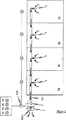
図1は、複数の観測領域(R1 ,R2 ,..,Rn )の中から、1つの観測領域(R1 ,R2 ,..,Rn )における火災発生を特定して検出するための、本発明による装置の好ましい実施形態を概略的に示している。本発明による装置は、図1に示すように、火災発生場所を正確に特定し得るような、中央に配置された吸引型の火災検出デバイスを備えている。図示の実施形態においては、このデバイスを使用することにより、4つの個別の観測領域(R1 ,R2 ,R3 ,R4 )を観測することができる。ここで、それぞれの観測領域(R1 ,..,R4 )の部屋内エアを代理する各エアサンプル(6)を、共通の吸引パイプシステム(3)を使用して、それぞれの観測領域(R1 ,..,R4 )から、連続的に抽出することができる。この目的のために、ブロワとして構成された吸引デバイス(5)が、吸引パイプシステム(3)の端部に、設置されている。吸引デバイス(5)によって共通の吸引パイプシステム(3)を通して抽出されたエアサンプル(6)は、1つのセンサあるいは複数のセンサ(7)に対して、供給される。これにより、1つまたは複数の火災パラメータを検出することができる。この場合、吸引デバイス(5)とセンサ(7)とを一緒に、1つの共通のハウジング(2)内に収容することが想定される。 1, a plurality of observation areas (R 1, R 2, .. , R n) from the, one observation region (R 1, R 2, .. , R n) detected by identifying a fire in Fig. 1 schematically shows a preferred embodiment of the device according to the invention for doing so. As shown in FIG. 1, the apparatus according to the present invention includes a suction type fire detection device disposed in the center so that the location of a fire can be accurately identified. In the illustrated embodiment, four separate observation regions (R 1 , R 2 , R 3 , R 4 ) can be observed by using this device. Here, each air sample (6) representing the room air of each observation region (R 1 ,..., R 4 ) is transferred to each observation region (R) using a common suction pipe system (3). R 1 ,..., R 4 ) can be extracted continuously. For this purpose, a suction device (5) configured as a blower is installed at the end of the suction pipe system (3). The air sample (6) extracted through the common suction pipe system (3) by the suction device (5) is supplied to one sensor or a plurality of sensors (7). Thereby, one or more fire parameters can be detected. In this case, it is envisaged that the suction device (5) and the sensor (7) are housed together in one common housing (2).
センサ(7)は、吸引パイプシステム(3)を介してエアサンプルが吸引されたときには、観測対象をなす観測領域(R1 ,..,R4 )内の部屋内エアを各々が代理する複数のエアサンプル(6)を分析するように機能する。ここで、センサ(7)として、従来技術において公知であるような任意のデバイスを使用し得ることは、明らかである。観測領域(R1 ,..,R4 )のどれかにおいて火災が発生した場合には、あるいは、観測領域(R1 ,..,R4 )の部屋内エアの中に火災パラメータが含有されている場合には、センサ(7)が、抽出された複数のエアサンプル(6)の中から火災パラメータを検出するとともに、対応する信号をコントローラ(9)に対して送出する。 When the air sample is sucked through the suction pipe system (3), the sensor (7) has a plurality of air in the room in the observation region (R 1 ,..., R 4 ) to be observed. It functions to analyze an air sample (6). Here, it is clear that any device as known in the prior art can be used as the sensor (7). If a fire occurs in any of the observation areas (R 1 , .., R 4 ), or the fire parameters are contained in the room air in the observation area (R 1 , .., R 4 ) If so, the sensor (7) detects a fire parameter from the plurality of extracted air samples (6) and sends a corresponding signal to the controller (9).
この信号に応答して、コントローラ(9)は、適切な制御信号を、吸引デバイス(5)に向けて送出し、その吸引デバイス(5)を停止させる。これと同時にあるいはこの直後に、コントローラ(9)は、ブロワデバイスを起動させるようなさらなる信号を送出し、これにより、ブロワデバイスを起動させる。ブロワデバイス(8)は、有利には、動作時には、既に抽出されたすべてのエアサンプル(6)と、吸引パイプシステム(3)の中になおも残存しているすべてのエアサンプル(6)と、を排出し得るようなものとして、構成される。図示の実施形態に関し、特に有利な態様においては、吸引デバイス(5)およびブロワデバイス(8)は、1つのブロワ(11)として構成される。このブロワ(11)は、コントローラ(9)から送出された信号に応答して、エア搬送方向を変更する。例示するならば、ブロワは、正逆回転可能なファンとすることができる。しかしながら、ブロワ(11)は、換気フラップを備えたファンとすることもできる。吸引パイプシステムからの排気を行った時点で、ブロワデバイス(8)は、新鮮なエアすなわち外部エアを、各観測領域(R1 ..,R4 )の個々の吸引開口(4)に対して供給する。これにより、新鮮なエアが、吸引パイプシステム(3)内に残存しているすべてのエアサンプル(6)を追い出す。残存エアサンプルは、例えば、各吸引開口(4)を通して、観測領域(R1 ,..,R4 )内へと注入される。 In response to this signal, the controller (9) sends an appropriate control signal towards the suction device (5) and stops the suction device (5). At the same time or shortly thereafter, the controller (9) sends a further signal to activate the blower device, thereby activating the blower device. The blower device (8) advantageously operates in operation with all air samples (6) already extracted and all air samples (6) still remaining in the suction pipe system (3). , Is configured to be capable of discharging. With regard to the illustrated embodiment, in a particularly advantageous manner, the suction device (5) and the blower device (8) are configured as one blower (11). The blower (11) changes the air conveyance direction in response to the signal sent from the controller (9). For example, the blower may be a fan that can rotate forward and backward. However, the blower (11) can also be a fan with a ventilation flap. At the time of performing the exhaust from the suction pipe system, a blower device (8), fresh air or outer air, each observation region (R 1 .., R 4) for each suction opening (4) Supply. This causes fresh air to expel all air samples (6) remaining in the suction pipe system (3). The remaining air sample is injected into the observation region (R 1 ,..., R 4 ) through each suction opening ( 4 ), for example.
本発明においては、コントローラ(9)は、吸引パイプシステム(3)からすべてのエアサンプル(6)が追い出された後に、ブロワデバイス(8)に対してさらなる信号を送出し、これにより、ブロワデバイス(8)を停止させる。これと同時にあるいはこれの直後に、コントローラ(9)は、吸引デバイス(5)を、再度起動する。これにより、吸引パイプシステム(3)によって、各観測領域(R1 ,..,R4 )の部屋内エアを代理する複数のエアサンプル(6)を、各観測領域(R1 ,..,R4 )から、再度抽出することができる。そして、センサ(7)に対して供給することができる。センサ(7)は、吸引デバイス(5)の再起動後におけるある時間の後に、抽出された複数のエアサンプル(6)内において、火災パラメータの存在を検出する。吸引デバイス(5)の再起動と、再抽出されたエアサンプル(6)内における火災パラメータの初期的検出と、の間の経過時間は、いわゆる輸送時間を規定するものであって、火災発生場所の特定に関する根拠として機能する。 In the present invention, the controller (9) sends a further signal to the blower device (8) after all air samples (6) have been expelled from the suction pipe system (3), whereby the blower device (8) is stopped. At the same time or immediately after this, the controller (9) activates the suction device (5) again. Thus, a plurality of air samples (6) representing the room air in each observation region (R 1 ,..., R 4 ) are converted into each observation region (R 1 ,. R 4 ) can be extracted again. And it can supply with respect to a sensor (7). The sensor (7) detects the presence of a fire parameter in the extracted air samples (6) after a certain time after restarting the suction device (5). The elapsed time between the restarting of the suction device (5) and the initial detection of the fire parameters in the re-extracted air sample (6) defines the so-called transport time and Serves as the basis for identification.
決定された輸送時間と理論的に計算された輸送時間とを例えば比較することによって輸送時間を評価し得るよう、プロセッサ(10)が設けられている。理論的に計算された輸送時間は、センサ(7)と、個々の観測領域(R1 ,..,R4 )の吸引開口(4)と、の間の距離に対して直接的に関連するものである。なぜなら、輸送時間が、以下のパラメータのうちの少なくとも1つに依存するからである。すなわち、センサ(7)と各観測領域(R1 ,..,R4 )の吸引開口(4)との間にわたっての吸引パイプシステム(3)の長さ;センサ(7)と各観測領域(R1 ,..,R4 )の吸引開口(4)との間にわたっての吸引パイプシステム(3)の実効的流通断面積;および、吸引パイプシステム(3)内におけるエアサンプル(6)の流速。したがって、センサ(7)と各観測領域(R1 ,..,R4 )の吸引開口(4)との間にわたっての吸引パイプシステム(3)の各長さおよび各断面積と、吸引パイプシステム(3)内におけるエアサンプル(6)の流速とを、少なくとも知ることにより、測定された輸送時間に基づいて、火災発生場所を特定することができる。 A processor (10) is provided so that the transport time can be evaluated, for example by comparing the determined transport time with a theoretically calculated transport time. The theoretically calculated transport time is directly related to the distance between the sensor (7) and the suction opening (4) of the individual observation region (R 1 ,..., R 4 ). Is. This is because the transit time depends on at least one of the following parameters: That is, the length of the suction pipe system (3) between the sensor (7) and the suction opening (4) of each observation region (R 1 ,..., R 4 ); the sensor (7) and each observation region ( the flow rate of the air samples (6) in and, the suction pipe system (3) within; R 1, .., R 4 effective cross-sectional flow area of the suction pipe system (3) over between the suction and opening (4) of) . Accordingly, the length and cross-sectional area of the suction pipe system (3) between the sensor (7) and the suction opening (4) of each observation region (R 1 ,..., R 4 ), and the suction pipe system By knowing at least the flow rate of the air sample (6) in (3), the location of the fire can be identified based on the measured transportation time.
本発明の好ましい実施形態は、さらに、吸引パイプシステム(3)内におけるエアサンプル(6)の流速を測定するためのセンサ(12)を備えている。プロセッサ(10)は、測定された流速を使用することによって、測定された輸送時間を評価することができる。しかしながら、流速を測定するためのセンサ(12)を設けないこともできる。その場合には、流速は、デバイスパラメータに基づいて決定される。例えば、吸引パイプシステム(3)の実効的流通断面積や、吸引デバイス(5)の吸引容量や、吸引開口(4)に対する断面形状および断面開口、に基づいて決定される。 The preferred embodiment of the present invention further comprises a sensor (12) for measuring the flow rate of the air sample (6) in the suction pipe system (3). The processor (10) can evaluate the measured transit time by using the measured flow rate. However, the sensor (12) for measuring the flow rate may not be provided. In that case, the flow rate is determined based on the device parameters. For example, it is determined based on the effective flow cross-sectional area of the suction pipe system (3), the suction capacity of the suction device (5), the cross-sectional shape and the cross-sectional opening with respect to the suction opening (4).
また、火災検出デバイスは、自己学習モードにおいて輸送時間を決定することができ、メモリ内に格納した表に基づいてすべての輸送時間を計算することができる。 The fire detection device can also determine the transit time in the self-learning mode and can calculate all transit times based on a table stored in the memory.
図2aは、吸引デバイス(5)およびブロワデバイス(8)の制御のために、センサ(7)から出力される信号を概略的に示すグラフであり、図2bは、吸引デバイス(5)およびブロワデバイス(8)の制御のために、コントローラ(9)から出力される信号を概略的に示すグラフである。ここで、x−軸は、時間を示している。一方、y−軸は、センサ(7)からの信号、あるいは、コントローラ(10)からの制御信号、を示している。t0 〜 t1 という時間区間においては、吸引デバイス(5)は、コントローラ(10)によって、連続的に動作するようにして、すなわち、観測領域(R1 ,..,R4 )からエアサンプル(6)を連続的に抽出するようにして、制御される。このプロセスは、図2bにおいては、一点鎖線を使用して示されている。時刻t1 においては、センサ(7)が、抽出されたエアサンプル(6)内において、火災パラメータの発生を検出している。この時刻t1 においてセンサ(7)から送出された信号に応答して、吸引デバイス(5)が停止され、また、それと同時に、ブロワデバイス(8)が起動される。ブロワ稼働時間は、t1 〜t2 という時間区間に対応している。この時間区間は、ブロワデバイス(8)の出力に依存し、また、吸引パイプシステム(3)の特定のパラメータに依存する。 FIG. 2a is a graph schematically showing a signal output from the sensor (7) for controlling the suction device (5) and the blower device (8), and FIG. 2b is a graph showing the suction device (5) and the blower. It is a graph which shows roughly the signal output from a controller (9) for control of a device (8). Here, the x-axis indicates time. On the other hand, the y-axis indicates a signal from the sensor (7) or a control signal from the controller (10). In the time interval from t 0 to t 1 , the suction device (5) is operated continuously by the controller (10), ie from the observation region (R 1 ,... R 4 ). (6) is controlled to be extracted continuously. This process is illustrated in FIG. 2b using a dashed line. At time t 1, the sensor (7) is in the extracted air samples (6) in, and detects the occurrence of fire parameters. In response to a signal sent from the sensor (7) at time t 1, the suction device (5) is stopped, At the same time, the blower device (8) is activated. The blower operating time corresponds to a time interval from t 1 to t 2 . This time interval depends on the output of the blower device (8) and on the specific parameters of the suction pipe system (3).
時刻t2 においては、吸引パイプシステム(3)の内部のすべてのエアサンプル(6)が追い出される。この時点で、コントローラ(9)は、ブロワデバイス(8)を停止させ、これと同時に、吸引デバイス(5)を再度起動させる。これにより、センサ(7)に対して、エアサンプル(6)が再度供給される。この場合、火災場所の特定には、輸送時間Δt1 〜Δt4 が使用される。輸送時間(Δt1 ,..,Δt4 )は、時刻t2 から、抽出したエアサンプル(6)内においてセンサ(7)が再び火災パラメータを検出する時刻t3 〜t6 までの、時間間隔である。輸送時間(Δt1 ,..,Δt4 )は、個々の観測領域(R1 ,..,R4 )に特有のものであり、分析によって火災発生場所を特定することができる。 In time t 2, the all air samples within the suction pipe system (3) (6) is expelled. At this point, the controller (9) stops the blower device (8) and simultaneously starts the suction device (5) again. Thereby, the air sample (6) is supplied again to the sensor (7). In this case, the transportation times Δt 1 to Δt 4 are used for specifying the fire place. The transport time (Δt 1 ,..., Δt 4 ) is a time interval from time t 2 to time t 3 to t 6 when the sensor (7) detects the fire parameter again in the extracted air sample (6). It is. The transport time (Δt 1 ,..., Δt 4 ) is specific to each observation region (R 1 , .., R 4 ), and the location of the fire can be specified by analysis.
3 吸引パイプシステム
4 吸引開口
5 吸引デバイス
6 エアサンプル
7 センサ
8 ブロワデバイス
9 コントローラ
10 プロセッサ
11 ブロワ
12 センサ
R1 観測領域
R2 観測領域
R3 観測領域
R4 観測領域
3 Suction Pipe System 4
Claims (21)
a)各観測領域(R1 ,..,Rn )の部屋内エアをそれぞれが含有した複数のエアサンプル(6)を、共通の吸引パイプシステム(3)を使用することによって、前記各観測領域(R1 ,..,Rn )から抽出し;
b)火災パラメータを検出し得る少なくとも1つのセンサ(7)を使用することにより、前記共通の吸引パイプシステム(3)を使用して抽出された前記エアサンプル(6)内において、少なくとも1つの火災パラメータを検出し;
このような方法において、さらに、
b’)前記火災パラメータを検出した時点で、前記エアサンプルの抽出を停止し;
c)この停止と同時にあるいはこの停止の直後に、ブロワデバイス(8)または吸引/ブロワデバイスを使用することにより、前記吸引パイプシステム(3)内へと抽出された前記エアサンプル(6)を前記観測領域(R1 ,..,Rn )へと追い出し;
c’)この追い出しが完了した時点で、前記エアサンプルの追い出しを停止し;
d)この停止と同時にあるいはこの停止の直後に、前記少なくとも1つのセンサ(7)がエアサンプル(6)内において火災パラメータを再検出するまで、前記吸引パイプシステム(3)を使用して、前記各観測領域(R1 ,..,Rn )から複数のエアサンプル(6)を再び抽出し;
e)この再抽出の開始時点から、前記ステップd)において再び抽出されたエアサンプルから火災パラメータが再検出されるまでに要した所要時間を測定し、これにより、前記複数の観測領域(R1 ,..,Rn )の中から、火災が発生しているあるいは火災が発生しようとしている1つの観測領域を特定し;
f)前記1つの観測領域内において火災が進展しているおよび/または存在していることを示す信号を、火災発生場所に関する情報を表示し得るインジケータ部材に対して、送出し、この場合、この信号に、前記複数の観測領域内において火災が発生している正確な観測領域の場所というさらなる情報を含有させる;
ことを特徴とする方法。A method for detecting and identifying fires and / or signs thereof in a plurality of observation regions (R 1 , R 2 , R 3 ,..., R n ),
a) A plurality of air samples (6) each containing in-room air in each observation region (R 1 ,..., R n ) can be obtained by using a common suction pipe system (3). Extracted from the region (R 1 ,..., R n );
b) At least one fire in the air sample (6) extracted using the common suction pipe system (3) by using at least one sensor (7) capable of detecting fire parameters. Detect parameters;
In such a method,
b ′) stopping the extraction of the air sample upon detection of the fire parameter;
c) Simultaneously with or immediately after this stop, the air sample (6) extracted into the suction pipe system (3) by using a blower device (8) or a suction / blower device Expelling to the observation area (R 1 ,..., R n );
c ′) when the expulsion is complete, stop expelling the air sample;
d) using the suction pipe system (3) until the at least one sensor (7) redetects a fire parameter in the air sample (6) at the same time or immediately after this stop, Extracting again a plurality of air samples (6) from each observation region (R 1 ,..., R n );
e) The time required from the start of this re-extraction to the re-detection of the fire parameters from the air sample extracted again in step d) is measured, and thereby the plurality of observation regions (R 1) are measured. , .., R n ) to identify one observation area where a fire is occurring or is about to occur;
f) A signal indicating that a fire is progressing and / or present within the one observation area is sent to an indicator member capable of displaying information on the location of the fire , in this case Including further information on the exact location of the observation area where the fire is occurring within the plurality of observation areas;
A method characterized by that.
前記ステップa)の後に、
a1)前記各観測領域(R1 ,..,Rn )からの各エアサンプル(6)の連続的な抽出時に、前記吸引パイプシステム(3)内におけるエアサンプル(6)の流速を決定し;
a2)前記吸引パイプシステム(3)内のすべてのエアサンプル(6)を前記観測領域(R1 ,..,Rn )へと完全に追い出すのに必要な時間を計算する;
ことを特徴とする方法。The method of claim 1, wherein
After step a)
a1) During the continuous extraction of each air sample (6) from each observation region (R 1 ,..., R n ), the flow rate of the air sample (6) in the suction pipe system (3) is determined. ;
a2) calculating the time required to completely expel all air samples (6) in the suction pipe system (3) to the observation region (R 1 ,..., R n );
A method characterized by that.
前記ステップc)の際に、追い出し時の流速を決定し、これにより、前記吸引パイプシステム(3)内のすべてのエアサンプル(6)を前記観測領域(R1 ,..,Rn )へと完全に追い出すのに必要な時間を計算することを特徴とする方法。The method according to claim 1 or 2, wherein
During the step c), the flow velocity at the time of expulsion is determined, whereby all the air samples (6) in the suction pipe system (3) are transferred to the observation region (R 1 ,..., R n ). And calculating the time required to completely evict.
前記ステップd)の後に、
d1)前記各観測領域(R1 ,..,Rn )からそれぞれ対応するエアサンプル(6)を再び抽出する際に、前記吸引パイプシステム(3)内におけるエアサンプル(6)の流速を決定し;
d2)前記各観測領域(R1 ,..,Rn )からそれぞれ対応するエアサンプル(6)を再び抽出する際に、前記各観測領域(R1 ,..,Rn )の部屋内エアをそれぞれが含有した各エアサンプル(6)に関して、各エアサンプル(6)の再抽出の開始時点から、これら各エアサンプルから火災パラメータが再検出されるまでに要する所要時間を計算する;
ことを特徴とする方法。The method according to any one of claims 1 to 3, wherein
After step d)
d1) The flow rate of the air sample (6) in the suction pipe system (3) is determined when the corresponding air sample (6) is extracted again from each observation region (R 1 ,..., R n ). And
d2) wherein each observation region (R 1, .., at the time of re-extracting the corresponding air samples (6) from R n), each observation area (R 1, .., in-room air R n) For each air sample (6) that each contains, calculate the time required from the start of re-extraction of each air sample (6) until the fire parameters are re-detected from each air sample;
A method characterized by that.
前記ステップd)において行うエアサンプルの前記再抽出を、前記ステップa)において行うエアサンプルの前記抽出と比較して、抽出速度を遅くして行うことを特徴とする方法。The method according to any one of claims 1 to 4, wherein
The method wherein the re-extraction of the air sample performed in step d) is performed at a slower extraction rate than the extraction of the air sample performed in step a).
さらに、自動調節手順を行い、この自動調節手順においては、
i)この自動調節手順を行っている全時間中にわたって、前記少なくとも1つのセンサ(7)から最も遠くに位置した観測領域(Rn )の吸引開口(4)のところにおいて、意図的に火災パラメータを生成し;
ii)前記少なくとも1つのセンサ(7)が、抽出されたエアサンプル(6)内において前記意図的に生成された火災パラメータを検出するまで、前記共通の吸引パイプシステム(3)を使用して、前記各観測領域(R1 ,..,Rn )からエアサンプル(6)を抽出し;
iii)ブロワデバイス(8)または吸引/ブロワデバイスを使用することにより、前記吸引パイプシステム(3)内へと抽出された前記エアサンプル(6)を前記観測領域(R1 ,..,Rn )へと追い出し;
iv)前記センサ(7)がエアサンプル(6)内において意図的に生成された火災パラメータを再検出するまで、前記吸引パイプシステム(3)を使用して、前記各観測領域(R1 ,..,Rn )から複数のエアサンプル(6)を再び抽出し;
v)この再抽出の開始時点から、前記ステップiv)において再び抽出されたエアサンプルから意図的に生成された火災パラメータが再検出されるまでに要した所要時間を測定し、これにより、前記吸引パイプシステムに関する最大所要時間を決定し;
vi)前記ステップv)において決定された前記最大所要時間に基づいて、および、前記吸引パイプシステム(3)の構成に基づいて、すなわち、複数の吸引開口(4)の間の間隔と、前記吸引パイプシステムの直径と、前記吸引開口(4)の直径と、に基づいて、前記各観測領域(R1 ,..,Rn )からの、前記各観測領域(R1 ,..,Rn )の部屋内エアをそれぞれが含有した複数のエアサンプル(6)に関してそれぞれの所要時間を計算し;
vii)各エアサンプル(6)に関して計算された所要時間を、表の形態で格納する;
ことを特徴とする方法。The method according to any one of claims 1 to 5, wherein
Furthermore, an automatic adjustment procedure is performed, and in this automatic adjustment procedure,
i) intentionally at the suction opening (4) of the observation area (R n ) furthest from the at least one sensor (7) during the entire time of this automatic adjustment procedure Produces;
ii) using the common suction pipe system (3) until the at least one sensor (7) detects the intentionally generated fire parameter in the extracted air sample (6); Extracting an air sample (6) from each observation region (R 1 ,..., R n );
iii) The air sample (6) extracted into the suction pipe system (3) by using a blower device (8) or a suction / blower device is used for the observation region (R 1 ,... R n). )
iv) using the suction pipe system (3) until the sensor (7) re-detects a fire parameter intentionally generated in the air sample (6), the respective observation regions (R 1 ,. ., R n ) again extract a plurality of air samples (6);
v) Measure the time required from the start of this re-extraction to the re-detection of the fire parameters intentionally generated from the air sample re-extracted in step iv), thereby the suction Determine the maximum time required for the pipe system;
vi) Based on the maximum duration determined in step v) and on the configuration of the suction pipe system (3), ie the interval between the suction openings (4) and the suction Based on the diameter of the pipe system and the diameter of the suction opening (4), each observation region (R 1 ,..., R n ) from each observation region (R 1 ,..., R n). ) For each of a plurality of air samples (6) each containing room air;
vii) store the calculated duration for each air sample (6) in the form of a table;
A method characterized by that.
前記ステップvii)に関する自動調節手順においては、
前記所要時間を表の形態として格納するに際しては、前記表内において前記各観測領域(R1 ,..,Rn )に関する所要時間を更新することを特徴とする方法。The method of claim 6 wherein:
In the automatic adjustment procedure for step vii),
When storing the required time in the form of a table, the required time for each observation region (R 1 ,..., R n ) is updated in the table .
火災発生時における前記所要時間の分析を、測定した所要時間と、前記自動調節手順において前記表として格納された所要時間に関する前記計算値と、を比較することにより、行うことを特徴とする方法。The method according to claim 6 or 7, wherein
A method of analyzing the required time at the time of fire occurrence by comparing the measured required time with the calculated value relating to the required time stored as the table in the automatic adjustment procedure.
前記所要時間の分析を、測定した所要時間と、前記各観測領域(R1 ,..,Rn )に関して理論的に計算された所要時間と、を比較することにより、行い、
その際、前記理論的な所要時間の計算を、
少なくとも1つのセンサ(7)と、前記各観測領域(R1 ,..,Rn )に関して前記吸引パイプシステム(3)内に配置された吸引開口(4)と、の間にわたっての、前記吸引パイプシステム(3)の長さと;
少なくとも1つのセンサ(7)と、前記各観測領域(R1 ,..,Rn )と、の間にわたっての、前記吸引パイプシステム(3)の実行流通断面積と;
少なくとも1つのセンサ(7)と、前記各観測領域(R1 ,..,Rn )の吸引開口(4)と、の間にわたっての、前記吸引パイプシステム(3)内におけるエアサンプル(6)の流速と;
の中の少なくとも1つのパラメータに基づいて行うことを特徴とする方法。The method according to any one of claims 1 to 8, wherein
Analyzing the required time by comparing the measured required time with the theoretically calculated required time for each observation region (R 1 ,..., R n );
At that time, the theoretical calculation of the required time is as follows:
The suction between at least one sensor (7) and a suction opening (4) arranged in the suction pipe system (3) with respect to each observation region (R 1 ,..., R n ) The length of the pipe system (3);
And at least one sensor (7), wherein each observation area (R 1, .., R n) and, over between the execution flow sectional area of the suction pipe system (3);
And at least one sensor (7), wherein each observation area (R 1, .., R n) suction opening (4), over during the, Rue A sample put into the suction pipe system (3) in The flow rate of (6);
A method based on at least one of the parameters.
前記各観測領域(R1 ,..,Rn )に対して接続されているとともに、少なくとも1つの吸引開口(4)を介することによって、前記各観測領域(R1 ,..,Rn )に対して連通している、吸引パイプシステム(3)と;
前記吸引パイプシステム(3)および前記吸引開口(4)を使用することにより、前記各観測領域(R1 ,..,Rn )からエアサンプル(6)を抽出するための吸引デバイス(5)と;
前記吸引パイプシステム(3)を通して吸引されたエアサンプル(6)内において少なくとも1つの火災パラメータを検出するための少なくとも1つのセンサ(7)と;
を具備し、
このような装置において、さらに、
前記吸引パイプシステム(3)内へと抽出されたすべてのエアサンプル(6)を前記観測領域(R1 ,..,Rn )へと追い出し得るものとされたブロワデバイス(8)と;
コントローラ(9)であるとともに、前記各観測領域(R1 ,..,Rn )からエアサンプル(6)を抽出させるように前記吸引デバイス(5)を駆動することができ、さらに、前記少なくとも1つのセンサ(7)がエアサンプル(6)内において少なくとも1つの火災パラメータを検出した際にはこの少なくとも1つのセンサ(7)から送出される信号に応答して前記吸引デバイス(5)を停止させることができ、この停止と同時にあるいはこの停止の直後に、前記吸引パイプシステム(3)内へと抽出されたすべてのエアサンプル(6)を前記観測領域(R1 ,..,Rn )へと追い出すように前記ブロワデバイス(8)を駆動することができ、さらに、前記追い出しが完了した時点で前記エアサンプルの追い出しを停止させるように前記ブロワデバイス(8)を停止させることができ、さらに、この停止と同時にあるいはこの停止の直後に、前記少なくとも1つのセンサ(7)がエアサンプル(6)内において火災パラメータを再検出するまで、前記吸引パイプシステム(3)を使用して、前記各観測領域(R1 ,..,Rn )から複数のエアサンプル(6)を再び抽出するように前記吸引デバイス(5)を駆動することができる、コントローラ(9)と;
プロセッサ(10)であるとともに、前記少なくとも1つのセンサ(7)がエアサンプル(6)内において火災パラメータを再検出した際には、前記再抽出の開始時点からその再検出までに要した所要時間を測定し、これにより、前記複数の観測領域(R1 ,..,Rn )の中から、火災が発生しているあるいは火災が発生しようとしている1つの観測領域を特定する、プロセッサ(10)と;
を具備していることを特徴とする装置。A fire detection device for detecting and identifying a fire and / or its sign in a plurality of observation areas (R 1 ,..., R n ),
Wherein each observation region (R 1, .., R n) with are connected to, by passing through at least one suction opening (4), wherein each observation area (R 1, .., R n) A suction pipe system (3) in communication with;
By using the suction pipe system (3) and the suction opening (4), a suction device (5) for extracting an air sample (6) from each observation region (R 1 ,..., R n ) When;
At least one sensor (7) for detecting at least one fire parameter in an air sample (6) sucked through the suction pipe system (3);
Comprising
In such a device,
A blower device (8) adapted to expel all air samples (6) extracted into the suction pipe system (3) into the observation area (R 1 ,..., R n );
The controller (9), the suction device (5) can be driven to extract an air sample (6) from each observation region (R 1 ,..., R n ), When one sensor (7) detects at least one fire parameter in the air sample (6), the suction device (5) is stopped in response to a signal sent from the at least one sensor (7) Simultaneously with this stop or immediately after this stop, all the air samples (6) extracted into the suction pipe system (3) are taken into the observation region (R 1 ,... R n ). The blower device (8) can be driven to expel the air sample, and further, the expulsion of the air sample is stopped when the expulsion is completed. The blower device (8) can be stopped, and at the same time or immediately after this stop, until the at least one sensor (7) redetects the fire parameter in the air sample (6). Using the suction pipe system (3) to drive the suction device (5) to again extract a plurality of air samples (6) from each observation region (R 1 ,..., R n ); Can with the controller (9);
When the fire parameter is detected again in the air sample (6) by the processor (10), the time required from the start of the re-extraction to the re-detection And a processor (10) that identifies one observation region where a fire has occurred or is about to occur from among the plurality of observation regions (R 1 ,..., R n ). )When;
The apparatus characterized by comprising.
前記複数の観測領域(R1 ,..,Rn )の中の1つの観測領域における火災発生場所を表示し得る少なくとも1つのインジケータ部材、および/または、前記複数の観測領域(R1 ,..,Rn )における火災の進展および/または存在に関する情報および前記複数の観測領域内における火災の正確な場所に関する情報を前記装置から離間した位置にまで送出し得る通信デバイス、を具備していることを特徴とする装置。The apparatus of claim 10.
At least one indicator member capable of displaying a fire occurrence location in one observation region among the plurality of observation regions (R 1 ,..., R n ), and / or the plurality of observation regions (R 1 ,. ., R n ), a communication device capable of transmitting information relating to the progress and / or presence of the fire and information relating to the exact location of the fire within the plurality of observation areas to a position remote from the device A device characterized by that.
所要時間の値を格納するためのメモリ手段を具備していることを特徴とする装置。12. The device according to claim 10 or 11,
A device comprising memory means for storing a value of the required time.
前記吸引開口(4)の近傍に配置されるとともに、前記装置の設定および検査を行い得るよう、火災パラメータを意図的に生成するための、少なくとも1つのスモーク生成源を具備していることを特徴とする装置。The apparatus according to any one of claims 10 to 12,
It is arranged in the vicinity of the suction opening (4) and comprises at least one smoke generation source for intentionally generating fire parameters so that the device can be set up and tested. Equipment.
前記吸引パイプシステム内におけるエアサンプルの流速を測定するための少なくとも1つのセンサ(12)を具備していることを特徴とする装置。The apparatus according to any one of claims 10 to 13,
Apparatus comprising at least one sensor (12) for measuring the flow rate of an air sample in the suction pipe system.
前記各吸引開口(4)の直径および/または横断面形状が、設置後に変更可能なものとされていることを特徴とする装置。The device according to any one of claims 10 to 14,
The diameter and / or cross-sectional shape of each suction opening (4) can be changed after installation.
前記少なくとも1つのセンサ(7)と、前記各観測領域(R1 ,..,Rn )と、の間にわたっての、前記吸引パイプシステム(3)の直径および/または横断面形状が、前記観測領域(R1 ,..,Rn )に対しての前記吸引パイプシステムの設置条件に応じて変更可能なものとされていることを特徴とする装置。The device according to any one of claims 10 to 15,
The diameter and / or cross-sectional shape of the suction pipe system (3) between the at least one sensor (7) and each observation region (R 1 ,..., R n ) A device characterized in that it can be changed according to the installation conditions of the suction pipe system for the region (R 1 ,..., R n ).
前記吸引デバイス(5)および前記ブロワデバイス(8)が、1つのブロワ(11)として互いに一緒のものとして構成され、
このブロワ(11)が、前記コントローラ(9)からの制御信号に応答してエア搬送の向きを変更するものとされていることを特徴とする装置。The apparatus according to any one of claims 10 to 16,
The suction device (5) and the blower device (8) are configured together as one blower (11),
The blower (11) is configured to change the direction of air conveyance in response to a control signal from the controller (9).
前記ブロワ(11)が、正逆回転可能なファンとされていることを特徴とする装置。The apparatus of claim 17.
The blower (11) is a device capable of rotating in the forward and reverse directions.
前記ブロワ(11)が、換気フラップを備えたファンとされていることを特徴とする装置。The apparatus of claim 17.
A device characterized in that the blower (11) is a fan with a ventilation flap.
前記観測領域(R1 ,..,Rn )内へと消化剤を投入し得る消火システムの中の火災検出部材として使用することを特徴とする方法。A method for using the device according to any one of claims 10 to 19, comprising:
A method for use as a fire detection member in a fire extinguishing system in which a digestive agent can be introduced into the observation region (R 1 ,..., R n ).
火災検出部材として請求項10〜19のいずれか1項に記載された装置を具備していることを特徴とする消火システム。A fire extinguishing system capable of injecting a digestive agent into a plurality of observation areas (R 1 ,..., R n ),
A fire extinguishing system comprising the device according to any one of claims 10 to 19 as a fire detection member.
Applications Claiming Priority (2)
| Application Number | Priority Date | Filing Date | Title |
|---|---|---|---|
| DE10348565A DE10348565B4 (en) | 2003-10-20 | 2003-10-20 | Method and device for detecting and locating a fire |
| PCT/EP2004/009450 WO2005048207A1 (en) | 2003-10-20 | 2004-08-24 | Method and device for identifying and localising a fire |
Publications (2)
| Publication Number | Publication Date |
|---|---|
| JP2007509390A JP2007509390A (en) | 2007-04-12 |
| JP4268189B2 true JP4268189B2 (en) | 2009-05-27 |
Family
ID=34484811
Family Applications (1)
| Application Number | Title | Priority Date | Filing Date |
|---|---|---|---|
| JP2006534603A Expired - Fee Related JP4268189B2 (en) | 2003-10-20 | 2004-08-24 | Method and apparatus for detecting and identifying a fire |
Country Status (17)
| Country | Link |
|---|---|
| EP (1) | EP1634261B1 (en) |
| JP (1) | JP4268189B2 (en) |
| KR (1) | KR100906206B1 (en) |
| CN (1) | CN100454346C (en) |
| AT (1) | ATE343191T1 (en) |
| AU (1) | AU2004290115B2 (en) |
| CA (1) | CA2538881C (en) |
| DE (2) | DE10348565B4 (en) |
| DK (1) | DK1634261T3 (en) |
| ES (1) | ES2274484T3 (en) |
| HK (1) | HK1084765A1 (en) |
| NO (1) | NO335293B1 (en) |
| PL (1) | PL1634261T3 (en) |
| PT (1) | PT1634261E (en) |
| RU (1) | RU2342709C2 (en) |
| TW (1) | TWI270826B (en) |
| WO (1) | WO2005048207A1 (en) |
Families Citing this family (39)
| Publication number | Priority date | Publication date | Assignee | Title |
|---|---|---|---|---|
| GB2430027A (en) * | 2005-09-09 | 2007-03-14 | Kidde Ip Holdings Ltd | Fibre bragg temperature sensors |
| DE102005052777A1 (en) * | 2005-11-04 | 2007-05-24 | Amrona Ag | Device for detecting fire in control cabinets |
| EP1811478B1 (en) | 2006-01-07 | 2008-04-02 | Hekatron Vertriebs GmbH | Fire detection method and device |
| US7581427B2 (en) * | 2006-11-14 | 2009-09-01 | Mocon, Inc. | Workspace analyte sensing system and method using a fan to move samples from the workspace to the sensor |
| JP4927619B2 (en) * | 2007-03-30 | 2012-05-09 | 能美防災株式会社 | Smoke detection system and smoke detection method |
| US8459369B2 (en) * | 2007-07-13 | 2013-06-11 | Firetrace Usa, Llc | Methods and apparatus for hazard control and signaling |
| GB0805063D0 (en) * | 2008-03-18 | 2008-04-23 | No Climb Products Ltd | Testing of aspirating systems |
| DE102009027034A1 (en) | 2009-06-18 | 2010-12-23 | Robert Bosch Gmbh | Monitoring system for monitoring area or device on occurrence of e.g. smoldering fire, has monitoring lines designed as hose lines, where data lines and/or power supply lines are embedded in wall material of monitoring lines or run on walls |
| KR20110100175A (en) | 2011-05-20 | 2011-09-09 | 주식회사 엔케이 | Gas type fire-fighting apparatus for a ship with double detective function |
| KR101125188B1 (en) * | 2011-09-08 | 2012-03-20 | 주식회사 엔케이 | Smoke detecting apparatus for fire extinguishment |
| RU2486594C2 (en) * | 2011-08-29 | 2013-06-27 | Закрытое акционерное общество "Видеофон МВ" | Method to monitor forest fires and complex system for early detection of forest fires built on principle of heterosensor panoramic view of area with function of highly accurate detection of fire source |
| WO2013032360A1 (en) * | 2011-08-31 | 2013-03-07 | ГЕРМАН, Дмитрий Александрович | Method and system for detecting and determining the location of unwanted substances in monitored zones and outlet unit for an air collector for such a system |
| EP2909588B1 (en) * | 2012-10-16 | 2022-06-29 | Xtralis Technologies Ltd | Addressability in particle detection |
| CN103177544B (en) * | 2012-12-18 | 2016-04-13 | 苏州热工研究院有限公司 | The tester of smoke detector that band purges |
| KR101465949B1 (en) * | 2013-06-03 | 2014-11-28 | 삼성중공업 주식회사 | Fire extinguishing apparatus, and cargo fire extinguishing system including the same |
| JP6442754B2 (en) * | 2013-11-11 | 2018-12-26 | 新コスモス電機株式会社 | Environmental monitoring system |
| KR20160097188A (en) * | 2013-10-16 | 2016-08-17 | 엑스트랄리스 테크놀로지 리미티드 | Aspirated Particle Detection with Various Flow Modifications |
| US9208671B2 (en) * | 2013-12-05 | 2015-12-08 | Honeywell International Inc. | Redundant input pipe networks in aspirated smoke detectors |
| AU2015226134B2 (en) * | 2014-03-06 | 2019-08-22 | Xtralis Global | Improvements to aspirated sampling systems |
| CN103969403B (en) * | 2014-05-09 | 2015-07-22 | 哈尔滨工程大学 | Method for measuring uniformity of ammonia gas concentration in SCR (silicon controller rectifier) system pipeline |
| CN104464166B (en) * | 2014-12-16 | 2016-08-31 | 公安部沈阳消防研究所 | A kind of air suction type fire detecting system based on open loop gas circuit and method |
| CN105158025A (en) * | 2015-07-30 | 2015-12-16 | 安徽中杰信息科技有限公司 | Hazardous-chemical-substance gas sampling whistle pipe |
| JP6662621B2 (en) * | 2015-11-30 | 2020-03-11 | 能美防災株式会社 | Smoke detector |
| CN105528850A (en) * | 2016-01-27 | 2016-04-27 | 博迈科海洋工程股份有限公司 | Arrangement method for smog detectors based on very early stage |
| RU2622787C1 (en) * | 2016-03-09 | 2017-06-20 | федеральное государственное бюджетное образовательное учреждение высшего образования "Южно-Российский государственный политехнический университет (НПИ) имени М.И. Платова" | Device for preventing ang fighting fires and method of its construction |
| KR102614489B1 (en) | 2016-12-01 | 2023-12-15 | 엘지전자 주식회사 | Dust measuring device |
| RU2663246C1 (en) * | 2017-03-20 | 2018-08-03 | Федеральное государственное казенное военное образовательное учреждение высшего образования "ВОЕННАЯ АКАДЕМИЯ МАТЕРИАЛЬНО-ТЕХНИЧЕСКОГО ОБЕСПЕЧЕНИЯ имени генерала армии А.В. Хрулева" | Method for the forest fire monitoring and complex system for early detection of forest fire |
| CN108687742A (en) * | 2018-08-23 | 2018-10-23 | 合肥合安智为科技有限公司 | A kind of pole incipient fire early warning intelligent inspection robot |
| JP6483907B1 (en) * | 2018-10-29 | 2019-03-13 | エア・ウォーター防災株式会社 | Foreign object detection device |
| JP2020204837A (en) * | 2019-06-14 | 2020-12-24 | 鹿島建設株式会社 | Fire monitoring system and fire monitoring method |
| KR102442054B1 (en) * | 2019-12-06 | 2022-09-13 | 한국건설기술연구원 | Toxic gas analysis system of real fire training center for refuge training according to smoke movement, and method for the same |
| KR102359775B1 (en) * | 2020-03-12 | 2022-02-08 | 케이아이티밸리(주) | Decision method of fire location using temperature sensors |
| EP3955226A1 (en) | 2020-08-12 | 2022-02-16 | Wagner Group GmbH | Suction particle detection system with fibre optic system |
| CN112581735A (en) * | 2020-12-14 | 2021-03-30 | 深圳市查知科技有限公司 | Fault positioning system and method for air-breathing smoke detector |
| EP4016490A1 (en) | 2020-12-18 | 2022-06-22 | Wagner Group GmbH | Method and test device for testing the functionality of a suction particle detecting system |
| DE102021204398A1 (en) | 2021-05-03 | 2022-04-07 | Siemens Schweiz Ag | Detection and localization of a fire in a rack storage system with aspirating smoke detectors or with linear heat detectors in a matrix arrangement |
| DE102021134312A1 (en) | 2021-12-22 | 2023-06-22 | Wagner Group Gmbh | Fluid for reversing the direction of flow |
| CN115171320B (en) * | 2022-06-29 | 2023-11-14 | 万霖消防技术有限公司 | Fire control monitoring method and system |
| CN116153013B (en) * | 2023-02-22 | 2024-02-09 | 营口天成消防设备有限公司 | Air suction type fire detection system and detection method based on machine smell |
Family Cites Families (11)
| Publication number | Priority date | Publication date | Assignee | Title |
|---|---|---|---|---|
| DE1061627B (en) * | 1956-02-16 | 1959-07-16 | Pyrene Co Ltd | United smoke tracer and fire extinguishing system |
| DE3139582C2 (en) * | 1981-10-05 | 1985-01-24 | Preussag AG Bauwesen, 3005 Hemmingen | Fire alarm device |
| NL187595C (en) * | 1981-10-08 | 1991-11-18 | Westinghouse Electrotechniek E | DEVICE FOR DETECTING GAS OR SMOKE PARTICLES. |
| US5103212A (en) * | 1989-07-03 | 1992-04-07 | Worcester Polytechnic Institute | Balanced fluid flow delivery system |
| FR2670010B1 (en) * | 1990-12-03 | 1994-05-06 | Cerberus Guinard | FUME DETECTION DEVICE BY SUCTION SYSTEM. |
| DE4125739A1 (en) * | 1991-08-02 | 1993-02-04 | Siemens Ag | Specimen extractor with several measurement points, e.g. for air in chemical plant - has extraction line with pumped transport medium, controlled inlet valves at each ,measurement point, and specific material sensor |
| JPH07506688A (en) * | 1992-05-11 | 1995-07-20 | ビジョン システムズ インコーポレイティド | Improvements to smoke detection scanning devices |
| GB2277625B (en) * | 1993-04-30 | 1996-08-28 | Kidde Fire Protection Ltd | Particle detecting apparatus and systems |
| US6125710A (en) * | 1997-04-15 | 2000-10-03 | Phoenix Controls Corporation | Networked air measurement system |
| GB9910540D0 (en) * | 1999-05-08 | 1999-07-07 | Airsense Technology Ltd | Method and apparatus |
| DE10125687B4 (en) * | 2001-05-25 | 2005-06-16 | Wagner Alarm- Und Sicherungssysteme Gmbh | Device for detecting sources of fire or gas contamination |
-
2003
- 2003-10-20 DE DE10348565A patent/DE10348565B4/en not_active Expired - Lifetime
-
2004
- 2004-08-24 DK DK04764427T patent/DK1634261T3/en active
- 2004-08-24 PT PT04764427T patent/PT1634261E/en unknown
- 2004-08-24 EP EP04764427A patent/EP1634261B1/en active Active
- 2004-08-24 AT AT04764427T patent/ATE343191T1/en active
- 2004-08-24 CA CA002538881A patent/CA2538881C/en not_active Expired - Fee Related
- 2004-08-24 AU AU2004290115A patent/AU2004290115B2/en not_active Ceased
- 2004-08-24 JP JP2006534603A patent/JP4268189B2/en not_active Expired - Fee Related
- 2004-08-24 WO PCT/EP2004/009450 patent/WO2005048207A1/en not_active Application Discontinuation
- 2004-08-24 CN CNB2004800287576A patent/CN100454346C/en not_active Expired - Fee Related
- 2004-08-24 PL PL04764427T patent/PL1634261T3/en unknown
- 2004-08-24 RU RU2006107768/09A patent/RU2342709C2/en active
- 2004-08-24 KR KR1020067007551A patent/KR100906206B1/en active IP Right Grant
- 2004-08-24 ES ES04764427T patent/ES2274484T3/en active Active
- 2004-08-24 DE DE502004001820T patent/DE502004001820D1/en active Active
- 2004-08-31 TW TW093126121A patent/TWI270826B/en not_active IP Right Cessation
-
2006
- 2006-04-18 NO NO20061699A patent/NO335293B1/en not_active IP Right Cessation
- 2006-04-21 HK HK06104793A patent/HK1084765A1/en not_active IP Right Cessation
Also Published As
| Publication number | Publication date |
|---|---|
| DE10348565A1 (en) | 2005-05-25 |
| CA2538881A1 (en) | 2005-05-26 |
| DE502004001820D1 (en) | 2006-11-30 |
| ATE343191T1 (en) | 2006-11-15 |
| ES2274484T3 (en) | 2007-05-16 |
| CA2538881C (en) | 2008-11-25 |
| AU2004290115A1 (en) | 2005-05-26 |
| AU2004290115B2 (en) | 2009-09-03 |
| WO2005048207A1 (en) | 2005-05-26 |
| HK1084765A1 (en) | 2006-08-04 |
| TW200519783A (en) | 2005-06-16 |
| TWI270826B (en) | 2007-01-11 |
| RU2342709C2 (en) | 2008-12-27 |
| JP2007509390A (en) | 2007-04-12 |
| PL1634261T3 (en) | 2007-01-31 |
| DK1634261T3 (en) | 2006-12-27 |
| NO20061699L (en) | 2006-04-18 |
| KR100906206B1 (en) | 2009-07-07 |
| PT1634261E (en) | 2007-01-31 |
| EP1634261A1 (en) | 2006-03-15 |
| NO335293B1 (en) | 2014-11-03 |
| CN1864181A (en) | 2006-11-15 |
| CN100454346C (en) | 2009-01-21 |
| EP1634261B1 (en) | 2006-10-18 |
| KR20060109872A (en) | 2006-10-23 |
| RU2006107768A (en) | 2007-11-10 |
| DE10348565B4 (en) | 2007-01-04 |
Similar Documents
| Publication | Publication Date | Title |
|---|---|---|
| JP4268189B2 (en) | Method and apparatus for detecting and identifying a fire | |
| US7375642B2 (en) | Method and device for identifying and localizing a fire | |
| TWI609175B (en) | Method and apparatus for determining at least one point of entry of smoke into a smoke detection system, and smoke detector | |
| EP2881922B1 (en) | Redundant input pipe networks in aspirated smoke detectors | |
| WO2015054749A1 (en) | Aspirated particle detection with various flow modifications | |
| US11024154B1 (en) | Self-testing fire sensing device | |
| US20210192913A1 (en) | Point detector for fire alarm system | |
| US20080048853A1 (en) | Backdraft Detector | |
| CN102007520B (en) | The test of suction system | |
| AU2013101580A4 (en) | Ventilation system | |
| JP2015518135A (en) | Method and device for controlling dynamic sealing of an enclosure | |
| US11609144B2 (en) | Detection of leakage in an aspirating fire detection system | |
| KR101166962B1 (en) | System and method of sensing a fire and including a smoke sensor having an identification number | |
| CN107780959A (en) | A kind of modified Control System of Tunnel Ventilation | |
| KR20090081537A (en) | System and methods to predict fire and smoke propagation | |
| Middleton et al. | Monitoring and control in the recirculation of underground ventilation air | |
| Grau et al. | Sniffer project development | |
| JPH06111165A (en) | Environment monitoring device, environment managing device and enviroment managing system |
Legal Events
| Date | Code | Title | Description |
|---|---|---|---|
| A131 | Notification of reasons for refusal |
Free format text: JAPANESE INTERMEDIATE CODE: A131 Effective date: 20080507 |
|
| A521 | Request for written amendment filed |
Free format text: JAPANESE INTERMEDIATE CODE: A523 Effective date: 20080805 |
|
| A131 | Notification of reasons for refusal |
Free format text: JAPANESE INTERMEDIATE CODE: A131 Effective date: 20080902 |
|
| A601 | Written request for extension of time |
Free format text: JAPANESE INTERMEDIATE CODE: A601 Effective date: 20081120 |
|
| A602 | Written permission of extension of time |
Free format text: JAPANESE INTERMEDIATE CODE: A602 Effective date: 20081128 |
|
| A521 | Request for written amendment filed |
Free format text: JAPANESE INTERMEDIATE CODE: A523 Effective date: 20081218 |
|
| TRDD | Decision of grant or rejection written | ||
| A01 | Written decision to grant a patent or to grant a registration (utility model) |
Free format text: JAPANESE INTERMEDIATE CODE: A01 Effective date: 20090120 |
|
| A01 | Written decision to grant a patent or to grant a registration (utility model) |
Free format text: JAPANESE INTERMEDIATE CODE: A01 |
|
| A61 | First payment of annual fees (during grant procedure) |
Free format text: JAPANESE INTERMEDIATE CODE: A61 Effective date: 20090219 |
|
| R150 | Certificate of patent or registration of utility model |
Free format text: JAPANESE INTERMEDIATE CODE: R150 |
|
| FPAY | Renewal fee payment (event date is renewal date of database) |
Free format text: PAYMENT UNTIL: 20120227 Year of fee payment: 3 |
|
| S111 | Request for change of ownership or part of ownership |
Free format text: JAPANESE INTERMEDIATE CODE: R313111 |
|
| FPAY | Renewal fee payment (event date is renewal date of database) |
Free format text: PAYMENT UNTIL: 20130227 Year of fee payment: 4 |
|
| R350 | Written notification of registration of transfer |
Free format text: JAPANESE INTERMEDIATE CODE: R350 |
|
| FPAY | Renewal fee payment (event date is renewal date of database) |
Free format text: PAYMENT UNTIL: 20130227 Year of fee payment: 4 |
|
| FPAY | Renewal fee payment (event date is renewal date of database) |
Free format text: PAYMENT UNTIL: 20140227 Year of fee payment: 5 |
|
| R250 | Receipt of annual fees |
Free format text: JAPANESE INTERMEDIATE CODE: R250 |
|
| R250 | Receipt of annual fees |
Free format text: JAPANESE INTERMEDIATE CODE: R250 |
|
| R250 | Receipt of annual fees |
Free format text: JAPANESE INTERMEDIATE CODE: R250 |
|
| LAPS | Cancellation because of no payment of annual fees |