JP4264792B2 - Exhaust gas cooling device - Google Patents
Exhaust gas cooling device Download PDFInfo
- Publication number
- JP4264792B2 JP4264792B2 JP2000384535A JP2000384535A JP4264792B2 JP 4264792 B2 JP4264792 B2 JP 4264792B2 JP 2000384535 A JP2000384535 A JP 2000384535A JP 2000384535 A JP2000384535 A JP 2000384535A JP 4264792 B2 JP4264792 B2 JP 4264792B2
- Authority
- JP
- Japan
- Prior art keywords
- exhaust gas
- air
- outer tube
- cooling device
- pipe
- Prior art date
- Legal status (The legal status is an assumption and is not a legal conclusion. Google has not performed a legal analysis and makes no representation as to the accuracy of the status listed.)
- Expired - Fee Related
Links
Images


Landscapes
- Treating Waste Gases (AREA)
- Chimneys And Flues (AREA)
Description
【0001】
【発明の属する技術分野】
本発明は、排ガスに冷却液を噴霧して冷却する排ガス冷却装置に係り、特に、硫黄酸化物等の有害成分を含む排ガスを冷却する排ガス冷却装置に関する。
【0002】
【従来の技術】
排ガス中の有害成分やダストの除去等を行う湿式の排ガス処理装置には、当該排ガス処理装置の入口部などに排ガス冷却装置を設けて、排ガスの加湿や冷却を行わせている。
【0003】
図4は従来における排ガス冷却装置1aの一例を示す断面図である。排ガス冷却装置1aは、二重管構造のものが一般的に知られている。同図に示すように排ガス2を流通させるダクト3の壁面に、外管4先端部を取り付ける。前記外管4には、軸心に沿って内管5が設けられており、当該内管5の基端側より冷却液6を供給する。前記内管5の先端部にはスプレーノズル7が取り付けてあり、当該スプレーノズル7より排ガス2流路に霧状冷却水8を供給しているのである。また、外管4は分岐管9を備えており、当該分岐管9よりエア10を外管4内に供給して、当該エア10によりスプレーノズル7の排ガス2からの冷却保護を図っていた。
【0004】
しかし、前記排ガス冷却装置1aは、スプレーノズル7をダクト3壁面近くに設けているため、外管4近傍のダクト3内で排ガス2の流れが乱されてしまう。このため排ガス5成分の混入した霧状冷却水8が、外管4先端面やダクト3壁面の下流側に付着する。そして、一定時間経過後には、前記付着した霧状冷却水8の水分が蒸発して、排ガス中のダストや硫黄酸化物等からなる汚染物11が残存する。前記霧状冷却水8の付着が連続的に起きると、それに伴い前記汚染物11が堆積して成長してしまう。このため、汚染物11の堆積した箇所が腐食してしまうという不具合を生じていた。
【0005】
そこで、このような問題を改善するために、図5に示したような排ガス冷却装置1bが提案されている。図5は従来における排ガス冷却装置1bの断面図である。前記排ガス冷却装置1aと同様の部材については、同一の番号を付している。排ガス冷却装置1bにおいては、内管5及び外管4の先端部がL型に屈曲しており、当該内管5及び外管4をスプレーノズル7の先端部が排ガス2下流方向に向くように配置している。このように、スプレーノズル7をダクト3の壁面から離れた位置に設けて、冷却液6を排ガス2下流方向に噴霧させることで、外管4やダクト3に霧状冷却水8が付着することの防止を図っている。この種の排ガス冷却装置としては、特開平7−256046号公報に開示されたものや、特開平8−10555号公報に開示されたものがある。
【0006】
【発明が解決しようとする課題】
しかし、従来における排ガス冷却装置には、以下のような問題があった。
図5に示した排ガス冷却装置1bにおいては、外管4の屈曲部12(12a、12b)でエア10の流れが乱れてしまい、エア10の速度が外管4先端部で不揃いとなる。エア10の速度が排ガス2の速度より遅くなると、排ガス2の流れが乱れ、排ガス2成分の混入した霧状冷却水8があおられてスプレーノズル7や外管4先端部に付着してしまう。このため、上記したように付着した箇所が汚染されてしまう。特に、スプレーノズル7が汚染されると冷却水6の噴射機能に支障をきたすため、短期間でスプレーノズル7を交換せざるを得ず、排ガス冷却装置の長期運転にも支障をきたしていた。
【0007】
本発明の目的は、前記従来技術の問題点を解決し、冷却水を噴霧するノズルを排ガスによる汚染から防止してノズルの長期使用を可能とするとともに、長期にわたり連続的に運転可能な排ガス冷却装置を提供することにある。
【0008】
【課題を解決するための手段】
上記目的を達成するために、本発明における排ガス冷却装置は、排ガスの流通経路に、エアを噴出する外管と、冷却液を供給する内管とを配置して、前記外管の先端側にエア旋回手段を設けるとともに、前記内管の先端部にノズルを取り付けて冷却液を噴霧可能として、当該旋回手段にて旋回させたエアを排ガスの流通経路に供給可能としたこと、を特徴とする構成とした。上記のように構成すると、内管に供給される冷却液は、内管先端部より排ガス流通経路に供給されて、排ガスと混合して排ガスを冷却する。一方、外管のエア流路を流通するエアは、エア流路の先端側に形成した旋回手段にて旋回流とされて、前記内管先端部より供給された冷却液の外周方向に排ガス流通経路に供給される。このようにしたため、ノズルは周囲の旋回流にて排ガスから保護され、排ガスによる汚染物がノズルに付着して、ノズルを腐食することを防止できる。これにより、ノズルの寿命を長くすることができる。また、ノズルを本来の予定寿命まで使用することができるため、ノズルを短期間に交換する必要がなくなり、排ガス冷却装置の長期間の連続運転を行うことができる。旋回流発生手段としては、エア流路の先端側に羽車状の部材を設けて形成してもよく、またエア流路の先端側に螺旋状にガイドを設けて形成してもよい。このとき、旋回流の旋回方向の速さは、排ガスの速さと同等かそれ以上となるようにすることが好ましい。このようにすると、旋回流内側への排ガスの流入をより確実に防止することができ、ノズルの腐食や汚染をより確実に防止することができる。また、前記エアの温度は、排ガスの温度と同程度としておくことが好ましい。このようにすると、外管先端部などへの結露の発生を防止することができ、より一層確実に外管先端部などの腐食や汚染を防止することができる。また、前記ノズルは、噴射する冷却液が付着しないように、外管の先端部から一定程度を有するよう突出させて設けることが好ましい。また、内管に供給される冷却液は1種類に限らない。また、排ガス冷却装置は、外管が内管を保護する2重管構造が好ましいが、これに限らず多重管構造としてもよい。
【0009】
上記構成において、前記旋回流発生手段は、前記外管及び内管は、排ガスの流通経路に直交または斜交するように延在してなり、それぞれの先端側に屈曲部または湾曲部を有して、それぞれの先端を排ガス下流方向に向けて配置してなり、前記旋回手段は、前記外管の屈曲部または湾曲部の入口側に取り付けた、孔を有したプレートとして、当該孔より前記外管の屈曲部または湾曲部にエアを導入可能とし、前記孔は、エアを前記外管の接線方向に沿って導入可能な位置に形成してあることを特徴とする構成としてよい。上記のように構成すると、環状のエア流路を流れるエアは、前記プレートに設けた孔より屈曲部または湾曲部(以下、曲部、という)入口側に流入する。前記孔によりエア流路が狭まったため、エアは孔を通過する際に圧力が高められる。そして、前記孔は、エアを前記外管の接線方向に沿って導入可能な位置に形成してあるため、孔を通過して曲部に流入したエアは、曲部の内壁面に案内されて当該内壁面に沿って移動する。従って、エアは内管を中心軸として螺旋状に旋回しつつ外管先端方向に移動して、ノズルの周囲を回りつつ排ガス下流方向に供給される。このように、圧力の高められた旋回流をノズルの周囲に供給できるため、ノズルの腐食や汚染をより確実に防止することができる。また、外管の曲部を利用してエアを自然に旋回流としているため、旋回流を発生させるために動力を用いる必要もなくコスト的にもメリットがある。なお、前記孔は、旋回流が発生しやすいようにプレート周縁部の上流側に形成することが好ましい。また、孔の大きさや位置により、外管に流入するエアの速度が同じでも発生する旋回流の速度や圧力を調整することができる。
【0010】
【発明の実施の形態】
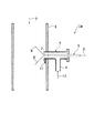
本発明の実施形態における排ガス冷却装置20について図面を用いて詳細に説明する。図1は、本実施形態における排ガス冷却装置20の断面図である。本実施形態においては、火力発電所にて発生した排ガス22を排ガス冷却装置20にて冷却する場合について説明する。なお、排ガス冷却装置20の適用対象としてはこれに限らず、排出されるガスを冷却する形態のものであれば適用することができるのはもちろんである。
【0011】
本実施形態においては、図1に示した上下方向に、円筒形状のダクト24を設けており、当該ダクト24の軸心方向に沿って排ガス24を上方から下方に流通させている。前記ダクト24の側壁は開口部26を有しており、当該開口部26に連結管28をダクト24の外方に突出するようにはめ込んでいる。
【0012】
そして、前記連結管28は、軸心方向に沿って貫通するように、外管30を保持している。前記外管30は、連結管28の基端面に設けたフランジ29と、当該フランジ29に当接する連結プレート31とで固定支持されている。前記外管30は、連結管28より外側に分岐管32を有している。前記分岐管32にはエア供給源(図示せず)が接続してあり、当該エア供給源から分岐管32を介して外管30内にエア34を流入できるようにしている。
【0013】
前記外管30は、ダクト24の略中心方向に向かって排ガス22流路を横断するように連結管28に保持されている。そして、前記外管30の先端部は略L字形状に屈曲しており、当該屈曲部は軸心が外管30の中心軸と直交するような円筒形状をなしている。そして、本実施形態においては、図1に示したように、前記外管屈曲部41の先端を下方に向けて、外管屈曲部41の軸心がダクト24の軸心と一致するように設けている。
【0014】
そして、前記外管30は、軸心方向に沿って貫通させた内管36を保持している。前記内管36は、外管30の基端面に設けたフランジ35と、当該フランジ35に当接して固着した連結プレート37とで固定支持されている。また、内管36は、外管30と同様に、先端側が略L字状に屈曲している。そして、内管屈曲部43も外管屈曲部41の軸心(本実施形態においてはダクト24の軸心と一致している)に沿って配置しており、内管屈曲部43先端を排ガス下流方向に臨ませている。このように内管36を配置したことにより、外管30内のエア流路38が環状に形成される。
【0015】
内管36の基端側は図示しない冷却液供給源に接続され、当該冷却液供給源により冷却液39が内管36に供給される。一方、内管屈曲部43先端には、スプレーノズル40が取り付けてあり、内管36を流入する冷却液39を噴霧できるようにしている。また、本実施形態においては、スプレーノズル40を外管30の先端部に対して10mm程度突出させて設けている。これにより、スプレーノズル40からの噴霧液48が外管30の先端部に付着することを防止して、外管30先端部の保護効果を高めている。
【0016】
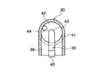
本実施形態においては、外管屈曲部41の入口側に、旋回手段を構成するプレート42を設けている。図2は、図1に示した排ガス冷却装置20のAA断面図である。そして、前記プレート42にはエア導入孔44を、エア34を前記外管30の接線方向に沿って導入可能な位置に形成してあり、詳細を後述するように旋回流46を発生させることができる。なお、前記エア導入孔44は、旋回流が発生しやすいようにプレート42周縁部の上流側に設けることが好ましい。また、前記エア導入孔44の大きさや位置により、外管30に流入するエア34の速度が同じでも発生する旋回流36の速度や圧力を調整することができる。
【0017】
上記のように構成した排ガス冷却装置20の作用について説明する。ダクト24内には、排ガス22がダクト24の軸心方向に沿って上側から下側に向かって流通している。そして、排ガス冷却装置20の内管36には、基端側に接続した冷却液供給源より冷却液39が供給されて、内管36の先端に設けたスプレーノズル40より排ガス22流路の下流側に噴霧液48を供給する。上記したように、内管屈曲部43の軸心はダクト24の軸心と一致しているため、冷却液39を排ガス22流路に放射状にほぼ均等に供給することができ、効率よく排ガス22の冷却を行わせることができる。
【0018】
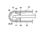
また、排ガス冷却装置20の外管30には、分岐管32よりエア34が供給され、供給されたエア34は環状に形成されたエア流路38をダクト24の軸心方向に向けて流入する。前記環状のエア流路38を流れるエア34は、前記プレート42にて流れが遮断されて、前記プレート42に設けたエア導入孔44より外管屈曲部41のエア流路38に流入する。図3は、図1に示した排ガス冷却装置20のBB断面図である。図3に示したように、前記エア導入孔44を通過する際にエア流路が大きく狭まる。このため、エア導入孔44を通過したエア34は通過前よりエア34の圧力が高くなっている。また、同図に示したように前記エア導入孔44は、エア34を前記外管30の接線方向に沿って導入可能な位置に形成してあるため、前記エア導入孔44を通過して外管屈曲部41に流入したエア34は、外管屈曲部41の内壁面に沿って移動して、エア34の軌道が前記内壁面の周方向に沿って曲げられる。前記エア34は先端側に向かう圧力を受けるため、内管36を中心軸とした螺旋状の旋回流46となり、外管30先端方向に移動してスプレーノズル40の周囲を回りつつ、排ガス22下流方向に供給される。このように、圧力の高められた旋回流46をスプレーノズル40の周囲に供給できるため、スプレーノズル40の腐食や汚染をより確実に防止することができる。また、本実施形態においては、外管屈曲部41のエア流路38の入口側に孔44を有したプレート42を取り付けることで旋回流発生手段を形成することができ、また屈曲部を利用してエア34を旋回流46としているため、旋回流46を発生させるための動力も不要である。従って、低コストかつ容易に旋回流46を発生させることができる。また、上記のように発生させた旋回流46は発生時に圧力が高められているため、スプレーノズル46の保護効果が高い。
【0019】
実施形態においては、内管36及び外管30の先端部が屈曲している場合に旋回流発生手段を構成する、孔44を備えたプレート42を設けた場合について説明したが、内管36及び外管30の先端部が湾曲している場合にも適用することができる。また、実施形態においては、内管36及び外管30が排ガス22の流路に対して直交するように設けた場合について説明したが、斜交するように設けてもよい。
【0020】
なお、旋回流発生手段としては、エア流路38の先端側に羽車状の部材を設けて形成してもよく、またエア流路38の先端側に螺旋状にガイドを設けて形成してもよい。このとき、旋回流46の速さは、排ガス22の速さと同等かそれ以上となるようにすることが好ましい。このようにすると、旋回流46内側への排ガス22の流入をより確実に防止することができ、スプレーノズル40の腐食や汚染をより確実に防止することができる。また、前記エア34の温度は、排ガス22の温度と同程度としておくことが好ましい。このようにすると、外管30先端部などへの結露の発生を防止することができ、より一層確実に腐食や汚染を防止することができる。また、内管36に供給される冷却液39は1種類に限らない。また、排ガス冷却装置20は、外管30が内管36を保護する2重管構造が好ましいが、これに限らず多重管構造としてもよい。また、ノズルの形態は、スプレーノズル40に限らず、他の形態を用いてもよい。
【0021】
【発明の効果】
以上説明したように、本発明において、ノズルは周囲の旋回流にて排ガスから保護され、排ガスによる汚染物のノズルへの付着、汚染物によるノズルの腐食をそれぞれ防止することができるため、ノズルの寿命を長くすることができる。また、ノズルを短期間に交換する必要がなくなるため、排ガス冷却装置の長期間の連続運転を行うことができる。
【0022】
また、本発明においては、圧力の高められた旋回流をノズルの周囲に供給できるため、ノズルの腐食や汚染をより確実に防止することができる。また、本発明においては、旋回流発生手段を容易に形成することができ、旋回流を発生させるために動力を用いる必要もないため、コスト的にもメリットがある。
【図面の簡単な説明】
【図1】本発明の実施形態における排ガス冷却装置を示す断面図である。
【図2】図1に示した排ガス冷却装置のAA断面図である。
【図3】図1に示した排ガス冷却装置のBB断面図である。
【図4】従来における排ガス冷却装置を示す断面図である。
【図5】従来における排ガス冷却装置を示す断面図である。
【符号の説明】
1a………排ガス冷却装置、1b………排ガス冷却装置、2………排ガス、
3………ダクト、4………外管、5………内管、6………冷却水、
7………スプレーノズル、8………霧状冷却水、9………分岐管、
10………エア、11………汚染物、12………屈曲部、
20………排ガス冷却装置、22………排ガス、24………ダクト、
26………開口部、28………連結管、29………フランジ、30………外管、31………連結プレート、32………分岐管、34………エア、
35………フランジ、36………内管、37………連結プレート、
38………エア流路、39………冷却液、40………スプレーノズル、
41………外管屈曲部、42………制御プレート、43………内管屈曲部、
44………エア導入孔、46………旋回流、48………霧状冷却水[0001]
BACKGROUND OF THE INVENTION
The present invention relates to an exhaust gas cooling device that cools exhaust gas by spraying a cooling liquid, and particularly relates to an exhaust gas cooling device that cools exhaust gas containing harmful components such as sulfur oxides.
[0002]
[Prior art]
In a wet type exhaust gas treatment apparatus that removes harmful components and dust in the exhaust gas, an exhaust gas cooling device is provided at an inlet of the exhaust gas treatment apparatus to humidify or cool the exhaust gas.
[0003]
FIG. 4 is a cross-sectional view showing an example of a conventional exhaust gas cooling device 1a. The exhaust gas cooling device 1a is generally known to have a double pipe structure. As shown in the figure, the outer tube 4 tip is attached to the wall surface of the duct 3 through which the
[0004]
However, since the exhaust gas cooling device 1a is provided with the spray nozzle 7 near the wall surface of the duct 3, the flow of the
[0005]
Therefore, in order to improve such a problem, an exhaust
[0006]
[Problems to be solved by the invention]
However, the conventional exhaust gas cooling apparatus has the following problems.
In the exhaust
[0007]
The object of the present invention is to solve the problems of the prior art described above, prevent the nozzle sprayed with cooling water from being contaminated by exhaust gas, and enable long-term use of the nozzle, and exhaust gas cooling that can be operated continuously over a long period of time. To provide an apparatus.
[0008]
[Means for Solving the Problems]
In order to achieve the above object, an exhaust gas cooling apparatus according to the present invention includes an outer pipe that ejects air and an inner pipe that supplies a cooling liquid in a flow path of exhaust gas, and is disposed at a distal end side of the outer pipe. An air swirling means is provided, and a nozzle is attached to the tip of the inner pipe so that the coolant can be sprayed, and the air swung by the swirling means can be supplied to the exhaust gas flow path. The configuration. If comprised as mentioned above, the cooling fluid supplied to an inner pipe will be supplied to an exhaust gas distribution path from the inner pipe front-end | tip part, will mix with waste gas, and will cool exhaust gas. On the other hand, the air flowing through the air flow path of the outer pipe is swirled by swirling means formed on the front end side of the air flow path, and the exhaust gas flows in the outer circumferential direction of the coolant supplied from the front end of the inner pipe. Supplied to the route. As a result, the nozzle is protected from the exhaust gas by the surrounding swirling flow, and it is possible to prevent the contaminant from the exhaust gas from adhering to the nozzle and corroding the nozzle. Thereby, the lifetime of a nozzle can be lengthened. In addition, since the nozzle can be used until the original expected life, it is not necessary to replace the nozzle in a short time, and the exhaust gas cooling device can be operated continuously for a long time. The swirling flow generating means may be formed by providing an impeller-like member on the front end side of the air flow path, or may be formed by providing a spiral guide on the front end side of the air flow path. At this time, the speed of the swirling flow in the swirling direction is preferably equal to or higher than the speed of the exhaust gas. If it does in this way, inflow of the exhaust gas inside swirl flow can be prevented more certainly, and corrosion and contamination of a nozzle can be prevented more certainly. Moreover, it is preferable that the temperature of the air is approximately the same as the temperature of the exhaust gas. In this way, it is possible to prevent the occurrence of condensation on the outer tube tip and the like, and it is possible to more reliably prevent corrosion and contamination of the outer tube tip and the like. Moreover, it is preferable that the nozzle is provided so as to protrude from the tip of the outer tube so as to have a certain degree so that the coolant to be injected does not adhere. Moreover, the coolant supplied to the inner pipe is not limited to one type. Further, the exhaust gas cooling device preferably has a double pipe structure in which the outer pipe protects the inner pipe, but is not limited to this and may have a multiple pipe structure.
[0009]
In the above configuration, in the swirl flow generating means, the outer tube and the inner tube extend so as to be orthogonal or oblique to the flow path of the exhaust gas, and have a bent portion or a curved portion at each distal end side. The swivel means is arranged as a plate having a hole attached to the inlet side of the bent portion or the curved portion of the outer tube, and is arranged from the hole to the outer side. Air may be introduced into a bent portion or a curved portion of the tube, and the hole may be formed at a position where air can be introduced along a tangential direction of the outer tube. If comprised as mentioned above, the air which flows through a cyclic | annular air flow path will flow in into a bending part or a curved part (henceforth a curved part) entrance side from the hole provided in the said plate. Since the air flow path is narrowed by the holes, the pressure of the air is increased when passing through the holes. And since the said hole is formed in the position which can introduce air along the tangential direction of the said outer tube | pipe, the air which flowed into the bending part through the hole is guided to the inner wall face of a bending part. It moves along the inner wall surface. Accordingly, the air is spirally swiveled around the inner tube as a central axis, moves in the direction of the outer tube tip, and is supplied in the exhaust gas downstream direction around the nozzle. Thus, since the swirl flow with increased pressure can be supplied around the nozzle, corrosion and contamination of the nozzle can be prevented more reliably. In addition, since air is naturally turned into a swirl flow using the curved portion of the outer tube, there is no need to use power to generate the swirl flow, and there is an advantage in cost. In addition, it is preferable to form the said hole in the upstream of a plate peripheral part so that a swirl flow may generate | occur | produce easily. Further, the speed and pressure of the swirling flow generated even when the speed of the air flowing into the outer pipe is the same can be adjusted by the size and position of the hole.
[0010]
DETAILED DESCRIPTION OF THE INVENTION
The exhaust gas cooling device 20 in the embodiment of the present invention will be described in detail with reference to the drawings. FIG. 1 is a cross-sectional view of the exhaust gas cooling device 20 in the present embodiment. In this embodiment, the case where the
[0011]
In the present embodiment, a
[0012]
The connecting
[0013]
The
[0014]
The
[0015]
The proximal end side of the
[0016]
In the present embodiment, a
[0017]
The operation of the exhaust gas cooling device 20 configured as described above will be described. In the
[0018]
In addition,
[0019]
In the embodiment, the description has been given of the case where the
[0020]
The swirling flow generating means may be formed by providing an impeller-like member on the front end side of the
[0021]
【The invention's effect】
As described above, in the present invention, the nozzle is protected from the exhaust gas by the surrounding swirling flow, and can prevent the contamination of the nozzle by the exhaust gas and the corrosion of the nozzle by the contamination. The lifetime can be extended. Further, since it is not necessary to replace the nozzle in a short time, the exhaust gas cooling device can be operated continuously for a long time.
[0022]
Further, in the present invention, since the swirl flow with increased pressure can be supplied around the nozzle, corrosion and contamination of the nozzle can be prevented more reliably. Further, in the present invention, the swirling flow generating means can be easily formed, and it is not necessary to use power to generate the swirling flow, so that there is an advantage in terms of cost.
[Brief description of the drawings]
FIG. 1 is a cross-sectional view showing an exhaust gas cooling device in an embodiment of the present invention.
2 is a cross-sectional view of the exhaust gas cooling device shown in FIG. 1 taken along line AA.
3 is a BB cross-sectional view of the exhaust gas cooling device shown in FIG.
FIG. 4 is a cross-sectional view showing a conventional exhaust gas cooling device.
FIG. 5 is a cross-sectional view showing a conventional exhaust gas cooling device.
[Explanation of symbols]
1a ......... exhaust gas cooling device, 1b ......... exhaust gas cooling device, 2 ......... exhaust gas,
3 .... duct, 4 .... outer tube, 5 .... inner tube, 6 .... cooling water,
7 ……… Spray nozzle, 8 ……… Mist cooling water, 9 ……… Branch pipe,
10 ... Air, 11 ... Pollution, 12 ... Bending
20 ......... Exhaust gas cooling device, 22 ......... Exhaust gas, 24 ......... Duct,
26 ......... Opening, 28 ......... Connecting tube, 29 ......... Flange, 30 ......... Outer tube, 31 ......... Connecting plate, 32 ......... Branch tube, 34 ......... Air,
35 ......... Flange, 36 ......... Inner tube, 37 ......... Connecting plate,
38 ... Air flow path, 39 ... Coolant, 40 ... Spray nozzle,
41 ......... Outer tube bent portion, 42 ......... Control plate, 43 ......... Inner tube bent portion,
44 ......... Air introduction hole, 46 ......... Swirl, 48 ......... Mist cooling water
Claims (2)
前記外管の先端側にエア旋回手段を設けるとともに、前記内管の先端部にノズルを取り付けて冷却液を噴霧可能として、当該旋回手段にて旋回させたエアを排ガスの流通経路に供給可能としたこと、を特徴とする排ガス冷却装置。In the exhaust gas distribution path, arrange an outer pipe that blows out air and an inner pipe that supplies coolant,
Air swirling means is provided on the distal end side of the outer pipe, and a nozzle is attached to the distal end portion of the inner pipe so that the coolant can be sprayed, and air swung by the swirling means can be supplied to the exhaust gas flow path. An exhaust gas cooling device characterized by that.
前記旋回手段は、前記外管の屈曲部または湾曲部の入口側に取り付けた、孔を有したプレートとして、当該孔より前記外管の屈曲部または湾曲部にエアを導入可能とし、
前記孔は、エアを前記外管の接線方向に沿って導入可能な位置に形成してあることを特徴とする請求項1に記載の排ガス冷却装置。The outer pipe and the inner pipe extend so as to be orthogonal or oblique to the exhaust gas flow path, and have a bent portion or a curved portion on each tip side, and each tip is directed to the exhaust gas downstream direction. Arranged,
The swivel means is a plate having a hole attached to a bent portion or a curved portion of the outer tube, and allows air to be introduced into the bent portion or the curved portion of the outer tube from the hole.
The exhaust gas cooling device according to claim 1, wherein the hole is formed at a position where air can be introduced along a tangential direction of the outer tube.
Priority Applications (1)
| Application Number | Priority Date | Filing Date | Title |
|---|---|---|---|
| JP2000384535A JP4264792B2 (en) | 2000-12-19 | 2000-12-19 | Exhaust gas cooling device |
Applications Claiming Priority (1)
| Application Number | Priority Date | Filing Date | Title |
|---|---|---|---|
| JP2000384535A JP4264792B2 (en) | 2000-12-19 | 2000-12-19 | Exhaust gas cooling device |
Publications (2)
| Publication Number | Publication Date |
|---|---|
| JP2002186820A JP2002186820A (en) | 2002-07-02 |
| JP4264792B2 true JP4264792B2 (en) | 2009-05-20 |
Family
ID=18851962
Family Applications (1)
| Application Number | Title | Priority Date | Filing Date |
|---|---|---|---|
| JP2000384535A Expired - Fee Related JP4264792B2 (en) | 2000-12-19 | 2000-12-19 | Exhaust gas cooling device |
Country Status (1)
| Country | Link |
|---|---|
| JP (1) | JP4264792B2 (en) |
Families Citing this family (7)
| Publication number | Priority date | Publication date | Assignee | Title |
|---|---|---|---|---|
| FR2881209B1 (en) * | 2005-01-21 | 2015-04-24 | Snecma Moteurs | GAS INCINERATOR INSTALLED ON A LIQUEFIED GAS TRANSPORT VESSEL |
| JP5116955B2 (en) * | 2005-07-13 | 2013-01-09 | 四国化工機株式会社 | Disinfectant gasifier |
| JP2009226282A (en) * | 2008-03-21 | 2009-10-08 | Taiyo Nippon Sanso Corp | Atomizing nozzle device |
| JP5087509B2 (en) * | 2008-09-19 | 2012-12-05 | 株式会社神鋼環境ソリューション | Temperature reduction tower |
| JP5379073B2 (en) * | 2009-06-09 | 2013-12-25 | 三星ダイヤモンド工業株式会社 | COOLING NOZZLE, COOLING METHOD USING THE COOLING NOZZLE, AND CRIMINATION METHOD FOR BRITTLE MATERIAL SUBSTRATE |
| JP7350711B2 (en) * | 2020-12-29 | 2023-09-26 | 株式会社クボタ | work vehicle |
| CN113996166B (en) * | 2021-10-22 | 2023-10-24 | 浙江宜可欧环保科技有限公司 | Method and device for deacidifying hot flue gas |
-
2000
- 2000-12-19 JP JP2000384535A patent/JP4264792B2/en not_active Expired - Fee Related
Also Published As
| Publication number | Publication date |
|---|---|
| JP2002186820A (en) | 2002-07-02 |
Similar Documents
| Publication | Publication Date | Title |
|---|---|---|
| JP5791569B2 (en) | Exhaust system | |
| WO2007116602A1 (en) | Flue gas denitration apparatus | |
| JP4264792B2 (en) | Exhaust gas cooling device | |
| JP2005127271A (en) | Urea water vaporizer | |
| SK281985B6 (en) | Water lance blower for cleaning heat exchangers | |
| ES2342738T3 (en) | PROCEDURE AND DEVICE FOR MIXING A GASEOUS FLUID WITH A LARGE GAS FLOW, ESPECIALLY TO INTRODUCE A REDUCING AGENT IN A SMOKE GAS CONTAINING NITROGEN OXIDES. | |
| KR102320605B1 (en) | gas scrubber | |
| HU210747B (en) | Lance | |
| JP6784386B2 (en) | Three-fluid nozzle and spraying method using the three-fluid nozzle | |
| EP0658128A1 (en) | A method and a device for reducing the pressure and the temperature of a steam in a steam conditioning valve. | |
| JP4346380B2 (en) | Three-fluid nozzle and waste treatment apparatus equipped with the three-fluid nozzle | |
| JP4836702B2 (en) | Air washer | |
| JP2004132642A (en) | Latent heat recovery type gas water heater | |
| JP3537292B2 (en) | Exhaust gas cooling tower | |
| JP2000351090A (en) | Laser thermal spraying nozzle | |
| JP3876006B2 (en) | Gas cooling system | |
| JP2731384B2 (en) | Water injection cooling device | |
| KR20190131524A (en) | Exhaust Gas Treatment System and Exhaust Gas Treatment Method | |
| JP3369051B2 (en) | Spray nozzle device in waste treatment facility | |
| CN208627647U (en) | A kind of protection sleeve pipe of spray gun tail end | |
| KR20080027904A (en) | Apparatus and method for decontamination for arc welding or cutting torches including jet nozzles having two concentric ejection zones | |
| KR960021104A (en) | Combined flue gas water cooling scrubber | |
| JPWO2019146348A1 (en) | Spray nozzle and spray method | |
| JPH05509258A (en) | Wet purification device, in particular for separating gaseous and/or liquid and/or solid impurities from a gas stream | |
| CN223096520U (en) | Laboratory ammonia-containing waste gas treatment device |
Legal Events
| Date | Code | Title | Description |
|---|---|---|---|
| A621 | Written request for application examination |
Free format text: JAPANESE INTERMEDIATE CODE: A621 Effective date: 20060314 |
|
| TRDD | Decision of grant or rejection written | ||
| A01 | Written decision to grant a patent or to grant a registration (utility model) |
Free format text: JAPANESE INTERMEDIATE CODE: A01 Effective date: 20090122 |
|
| A01 | Written decision to grant a patent or to grant a registration (utility model) |
Free format text: JAPANESE INTERMEDIATE CODE: A01 |
|
| A61 | First payment of annual fees (during grant procedure) |
Free format text: JAPANESE INTERMEDIATE CODE: A61 Effective date: 20090204 |
|
| R150 | Certificate of patent (=grant) or registration of utility model |
Free format text: JAPANESE INTERMEDIATE CODE: R150 |
|
| FPAY | Renewal fee payment (prs date is renewal date of database) |
Free format text: PAYMENT UNTIL: 20120227 Year of fee payment: 3 |
|
| FPAY | Renewal fee payment (prs date is renewal date of database) |
Free format text: PAYMENT UNTIL: 20130227 Year of fee payment: 4 |
|
| LAPS | Cancellation because of no payment of annual fees |