JP4259298B2 - Image display system and image display method - Google Patents
Image display system and image display method Download PDFInfo
- Publication number
- JP4259298B2 JP4259298B2 JP2003403004A JP2003403004A JP4259298B2 JP 4259298 B2 JP4259298 B2 JP 4259298B2 JP 2003403004 A JP2003403004 A JP 2003403004A JP 2003403004 A JP2003403004 A JP 2003403004A JP 4259298 B2 JP4259298 B2 JP 4259298B2
- Authority
- JP
- Japan
- Prior art keywords
- image display
- information
- video information
- image
- display device
- Prior art date
- Legal status (The legal status is an assumption and is not a legal conclusion. Google has not performed a legal analysis and makes no representation as to the accuracy of the status listed.)
- Expired - Lifetime
Links
- 238000000034 method Methods 0.000 title description 8
- 238000000605 extraction Methods 0.000 claims description 5
- 230000006870 function Effects 0.000 description 34
- 238000012545 processing Methods 0.000 description 34
- 230000005540 biological transmission Effects 0.000 description 20
- 238000004891 communication Methods 0.000 description 11
- 239000004973 liquid crystal related substance Substances 0.000 description 10
- 238000010586 diagram Methods 0.000 description 6
- 238000009434 installation Methods 0.000 description 2
- 230000002093 peripheral effect Effects 0.000 description 2
- 230000008859 change Effects 0.000 description 1
- 230000000694 effects Effects 0.000 description 1
- 238000012986 modification Methods 0.000 description 1
- 230000004048 modification Effects 0.000 description 1
- 230000008569 process Effects 0.000 description 1
- 230000000007 visual effect Effects 0.000 description 1
Images


Landscapes
- Facsimiles In General (AREA)
- Two-Way Televisions, Distribution Of Moving Picture Or The Like (AREA)
- Information Transfer Between Computers (AREA)
Description
本発明は、駅やデパートなどに設置され、時計画像により時刻情報を表示するとともに、随時必要な映像情報を表示する画像表示システム、及び画像表示方法に関する。 The present invention relates to an image display system and an image display method that are installed in a station, a department store, or the like, and display time information using a clock image and display necessary video information as needed.
駅やデパートなど、多くの人々が集まる場所には、壁際などに多数の案内広告などが掲示されている。最近はこうした案内広告に、電子式の画像表示装置が多く利用されるようになってきた。この画像表示装置は、従来の紙を用いたポスターなどの固定的な案内広告などと異なり、ポスターなどの張り替えの必要がなく、また、案内広告などの内容をタイムリーに変更でき、また、ニュースや時刻情報などを提供することができるなど利点が多い。 In places where many people gather, such as stations and department stores, many informational advertisements are posted on the walls. Recently, many electronic image display devices have been used for such guidance advertisements. Unlike conventional guide advertisements such as posters using paper, this image display device does not require posters to be replaced, and the contents of guide advertisements can be changed in a timely manner. There are many advantages such as providing time information and time information.
ところで、例えばデパートなどで、各階や各売場などに多数の画像表示装置を設置し、常時は時計画像で時刻情報を提供し、必要に応じて、バーゲンやイベントなどの案内情報を表示するような利用が行われるようになってきた。このような時計画像と案内情報を同時に表示するような場合は、従来は、各画像表示装置の管理と、時計画像と共に表示させる案内情報として何を表示するかは全て中央の管理サーバで集中管理されており、各画像表示装置は管理サーバから配信された映像情報をそのまま表示していた。 By the way, in a department store, for example, a large number of image display devices are installed on each floor, each sales floor, etc., and time information is always provided in a clock image, and information such as bargains and events is displayed as needed. The use has come to be done. When such a clock image and guidance information are displayed at the same time, conventionally, management of each image display device and what is displayed as guidance information to be displayed together with the clock image are all centrally managed by a central management server. Each image display device displays the video information distributed from the management server as it is.
しかしながら、画像表示装置が多数の場所に設置されている場合に、各画像表示装置の設置場所や時間帯に合わせて適切な画像を選択して表示することが必要なこともある。このような場合には、管理サーバでの処理ソフトウェアが複雑かつ膨大なものとなり、プログラムの開発とその管理に多大な労力を要していた。そのため、各画像表示装置に画一的な画像を表示させることで済ますことも多かった。 However, when the image display device is installed in many places, it may be necessary to select and display an appropriate image in accordance with the installation place and time zone of each image display device. In such a case, the processing software on the management server becomes complicated and enormous, and much effort is required for program development and management. For this reason, it is often sufficient to display a uniform image on each image display device.
このような画像表示装置に関連する先行技術として、駅などに設置された多数の看板を自動的に運営管理できる電子看板システムが提供されている。これは、鉄道駅などに設置された多数の看板スクリーンに液晶プロジェクターなどを用いて広告画像(静止画、動画、文字情報など)を表示する装置であり、液晶プロジェクターPHS端末を有し、無線電話通信を通じてサーバから広告画像を受信し、内部に蓄積し、看板スクリーンに表示すする。また、時間帯ごとに広告画像を切替えることができる。サーバは、遠隔から液晶プロジェクターに対して、制御コマンドや、広告画像の更新データや、文字情報などを送信する(例えば、特許文献1)。
しかしながら、従来の画像表示装置(電子看板など)においては、多数の画像表示装置で表示させる映像情報を中央のサーバで一括管理し、時刻毎に画像表示端末装置に必要な表示情報を選択して配信していた。このため、多数の画像表示装置が設置されている場合には、画像表示装置毎の映像情報の配信制御が複雑となり、その管理には多大の労力を必要としていた。 However, in a conventional image display device (such as an electronic signboard), video information displayed on a large number of image display devices is collectively managed by a central server, and display information necessary for the image display terminal device is selected at each time. It was delivered. For this reason, when a large number of image display devices are installed, distribution control of video information for each image display device becomes complicated, and management thereof requires a great deal of labor.
本発明は、上記課題に鑑みてなされたものであり、本発明の目的は、時刻情報を提供する時計画像を表示すると共に、随時必要な映像情報の表示を行う画像表示装置が多数設置された場合にも、その制御と管理を容易にする、画像表示システム、及び画像表示方法を提供することにある。 The present invention has been made in view of the above problems, and an object of the present invention is to display a clock image that provides time information and a number of image display devices that display necessary video information as needed. In some cases, the present invention also provides an image display system and an image display method that facilitate control and management.
本発明の画像表示システムは、複数の画像表示装置と前記各画像表示装置に映像情報を送信する映像情報送信装置とがネットワークを介して接続された画像表示システムであって、
前記映像情報送信装置は、前記各画像表示装置に送信する映像情報を記憶する映像情報記憶手段と、前記各画像表示装置の端末識別情報毎に、前記画像表示装置が表示すべき映像情報と表示開始時刻とを関連づけて記憶する表示開始テーブル記憶手段と、前記画像表示装置から前記画像表示装置の前記端末識別情報を受信した場合に、前記端末識別情報と現在の時刻を基に表示開始テーブルを参照し、前記画像表示装置が表示すべき映像情報と表示開始時刻の情報とを抽出する映像情報抽出手段と、前記映像情報抽出手段により抽出された前記映像情報と前記表示開始時刻を前記画像表示装置に送信する表示情報送信手段とを備え、
前記画像表示装置は、時計機能と、前記画像表示装置の端末識別情報を定期的に前記映像情報送信装置に送信する端末識別情報送信手段と、前記映像情報送信装置から受信した映像情報と表示開始時刻の情報に基づいて、表示開始時刻に、受信した映像情報を表示する映像表示手段とを備えることを特徴とする。
The image display system of the present invention is an image display system in which a plurality of image display devices and a video information transmission device that transmits video information to each of the image display devices are connected via a network,
The video information transmitting device includes video information storage means for storing video information to be transmitted to each image display device, and video information to be displayed by the image display device and display for each terminal identification information of each image display device. A display start table storing means for associating and storing a start time; and when receiving the terminal identification information of the image display device from the image display device, a display start table based on the terminal identification information and the current time The video information extracting means for extracting the video information to be displayed by the image display device and the display start time information, and the video information and the display start time extracted by the video information extracting means are displayed in the image. Display information transmitting means for transmitting to the device,
The image display device includes a clock function, terminal identification information transmitting means for periodically transmitting terminal identification information of the image display device to the video information transmitting device, video information received from the video information transmitting device, and display start. And a video display means for displaying the received video information at the display start time based on the time information.
このような構成であれば、映像情報送信装置(中央の管理サーバ)は、各画像表示装置(端末)に配信する映像情報をデータベースに記憶すると共に、各画像表示装置の端末識別情報に対応して、当該画像表示装置が表示すべき映像情報の識別情報とその表示開始時刻の情報とを表示開始テーブルとして記憶する。そして、各画像表示装置は、定期的(または表示終了など必要なとき)に、各画像表示装置自身の端末識別情報を、映像情報の要求信号として、映像情報送信装置に送信する。映像情報送信装置(サーバ)は、画像表示装置からの端末識別情報を受信した場合に、該端末識別情報を基に表示開始テーブルを参照し、当該画像表示装置が表示すべき映像情報とその表示開始時刻の情報とを抽出し、抽出した映像情報とその表示開始時刻の情報を、当該画像表示装置に送信する。画像表示装置では、映像情報送信装置から受信した映像情報を、その表示開始時刻が到来すると表示を開始する。 With such a configuration, the video information transmitting device (central management server) stores the video information to be distributed to each image display device (terminal) in the database and corresponds to the terminal identification information of each image display device. Thus, the identification information of the video information to be displayed by the image display device and the information of the display start time are stored as a display start table. Each image display device transmits the terminal identification information of each image display device itself as a request signal for video information to the video information transmission device periodically (or when display termination is necessary). When receiving the terminal identification information from the image display device, the video information transmitting device (server) refers to the display start table based on the terminal identification information, and displays the video information to be displayed by the image display device and the display thereof. The start time information is extracted, and the extracted video information and the display start time information are transmitted to the image display device. The image display apparatus starts displaying the video information received from the video information transmitting apparatus when the display start time arrives.
これにより、画像表示装置(端末)側から自身が必要とする映像情報を映像情報送信装
置(サーバ)側に要求し、受信した映像情報を自身で表示することができる。すなわち、
画像表示装置はプル型で映像情報送信装置から映像情報を取得して自立的に表示を行おこ
なうため、各設置場所や時間対帯ごとに必要な情報を提供することができる。例えば、デ
パートなどでは、紳士服売場では婦人服売場のバーゲンの案内は行わないなど、表示する
情報を選択して売場に合致したものとすることができる。また、時刻に会わせて、各階に
客を誘導するように情報を表示することも可能となる。さらに、映像情報送信装置(サー
バ)側で、個々の画像表示装置の表示制御を行う必要がなくなり、映像情報の配信制御と
その管理が容易となる。
Thereby, the video information required by the image display apparatus (terminal) can be requested to the video information transmission apparatus (server) side, and the received video information can be displayed by itself. That is,
The image display device can provide order to perform row autonomously acquires and displays video information from the video information transmitting apparatus in pull type, information required for each location and time to zone. For example, in a department store or the like, information to be displayed can be selected and matched with the sales floor, such as no bargain guidance for the women's clothing sales floor is provided at the men's clothing sales floor. In addition, it is possible to display information so as to guide customers to each floor according to the time. Furthermore, it is not necessary to perform display control of individual image display devices on the video information transmitting device (server) side, and video information distribution control and management thereof are facilitated.
また、本発明の画像表示システムは、前記画像表示装置は、前記映像情報を表示しない間は、前記時計画像を常時表示することを特徴とする。
このような構成であれば、画像表示装置では、映像情報を表示しない場合には、時計画像により常時時刻情報を表示する。例えば、アナログ式の時計画像などを表示する。
これにより、画像表示にブランクを生じさせることなく、周囲との視覚的な調和を保ちながら、かつ有効な情報を提供することができる。
The image display system of the present invention is characterized in that the image display device always displays the clock image while the video information is not displayed.
With such a configuration, the image display device always displays time information using a clock image when the video information is not displayed. For example, an analog clock image is displayed.
Accordingly, it is possible to provide effective information while maintaining visual harmony with the surroundings without causing a blank in the image display.
また、本発明の画像表示システムは、前記画像表示装置における前記時計画像表示手段は、前記映像情報を表示している間にも、前記時計画像を常時表示することを特徴とする。
このような構成であれば、画像表示装置では、映像情報を表示する場合にも、同時に時計画像を表示する。
これにより、例えば、イベント情報をイベント開始時刻とともに表示する場合には、現時時刻を同時に確認できる。また、前から表示されている時計画像の上に、文字情報などの案内情報を流すような場合には、画像が急に変化せず、自然な画面の流れとなる。
The image display system of the present invention is characterized in that the clock image display means in the image display device always displays the clock image even while the video information is displayed.
With such a configuration, the image display device simultaneously displays a clock image when displaying video information.
Thereby, for example, when displaying the event information together with the event start time, the current time can be confirmed at the same time. In addition, when guide information such as character information is flowed on the clock image displayed from the front, the image does not change suddenly and a natural screen flow is obtained.
また、本発明の画像表示方法は、前記映像情報送信装置は、前記各画像表示装置の端末識別情報毎に、前記画像表示装置が表示すべき映像情報と表示開始時刻とを表示開始テーブルとして関連づけて記憶し、前記画像表示装置から前記画像表示装置の前記端末識別情報を受信した場合に、前記端末識別情報と現在の時刻を基に表示開始テーブルを参照し、前記画像表示装置が表示すべき映像情報と表示開始時刻の情報とを抽出し、抽出した前記映像情報と前記表示開始時刻を前記画像表示装置に送信し、
前記画像表示装置は、前記画像表示装置の端末識別情報を定期的に前記映像情報送信装置に送信し、前記映像情報送信装置から受信した映像情報と表示開始時刻の情報に基づいて、表示開始時刻に、受信した映像情報を表示することを特徴とする。
In the image display method of the present invention, the video information transmitting device associates video information to be displayed by the image display device with a display start time as a display start table for each terminal identification information of each image display device. And when the terminal identification information of the image display device is received from the image display device, the image display device should display by referring to the display start table based on the terminal identification information and the current time. Video information and display start time information are extracted, the extracted video information and the display start time are transmitted to the image display device,
The image display device periodically transmits the terminal identification information of the image display device to the video information transmission device, and based on the video information received from the video information transmission device and the display start time information, the display start time In addition, the received video information is displayed.
このような手順であれば、映像情報送信装置(中央の管理サーバ)は、各画像表示装置(端末)に配信する映像情報をデータベースに記憶すると共に、各画像表示装置の端末識別情報に対応して、当該画像表示装置が表示すべき映像情報識別情報とその表示開始時刻の情報とを表示開始テーブルとして記憶する。そして、各画像表示装置は、定期的(または表示終了など必要なとき)に、各画像表示装置自身の端末識別情報を、映像情報の要求信号として、映像情報送信装置に送信する。映像情報送信装置(サーバ)は、画像表示装置からの端末識別情報を受信した場合に、該端末識別情報を基に表示開始テーブルを参照し、当該画像表示装置が表示すべき映像情報とその表示開始時刻の情報とを抽出し、抽出した映像情報とその表示開始時刻の情報を、当該画像表示装置に送信する。画像表示装置では、映像情報送信装置から受信した映像情報を、その表示開始時刻が到来すると表示を開始する。 With such a procedure, the video information transmitting device (central management server) stores the video information to be distributed to each image display device (terminal) in the database and corresponds to the terminal identification information of each image display device. Thus, the video information identification information to be displayed by the image display device and the display start time information are stored as a display start table. Each image display device transmits the terminal identification information of each image display device itself as a request signal for video information to the video information transmission device periodically (or when display termination is necessary). When receiving the terminal identification information from the image display device, the video information transmitting device (server) refers to the display start table based on the terminal identification information, and displays the video information to be displayed by the image display device and the display thereof. The start time information is extracted, and the extracted video information and the display start time information are transmitted to the image display device. The image display apparatus starts displaying the video information received from the video information transmitting apparatus when the display start time arrives.
これにより、画像表示装置(端末)側から自身が必要とする映像情報を映像情報送信装
置(サーバ)側に要求し、受信した映像情報を自身で表示することができる。すなわち、
画像表示装置はプル型で映像情報送信装置から映像情報を取得して自立的に表示を行おこ
なうため、各設置場所や時間帯ごとに必要な情報を提供することができる。例えば、デパ
ートなどでは、紳士服売場では婦人服売場のバーゲンの案内は行わないなど、表示する情
報を選択して売場に合致したものとすることができる。また、時刻に会わせて、各階に客
を誘導するように情報を表示することも可能となる。さらに、映像情報送信装置(サーバ
)側で、個々の画像表示装置の表示制御を行う必要がなくなり、映像情報の配信制御とそ
の管理が容易となる。
Thereby, the video information required by the image display apparatus (terminal) can be requested to the video information transmission apparatus (server) side, and the received video information can be displayed by itself. That is,
The image display device can provide order to perform row autonomously acquires and displays video information from the video information transmitting apparatus in pull type, information required for each location and time zone. For example, in a department store or the like, information to be displayed can be selected and matched with the sales floor, such as no bargain guidance for the women's clothing sales floor is provided at the men's clothing sales floor. In addition, it is possible to display information so as to guide customers to each floor according to the time. Furthermore, it is not necessary to perform display control of individual image display devices on the video information transmitting device (server) side, and video information distribution control and management thereof are facilitated.
次に本発明を実施するための最良の形態について図面を参照して説明する。 Next, the best mode for carrying out the present invention will be described with reference to the drawings.
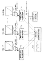
図1は、本発明による画像表示システムの概念を説明するための図であり、本発明の画像表示システムをデパートなどに設置する場合の例を示したものである。 FIG. 1 is a diagram for explaining the concept of an image display system according to the present invention, and shows an example in which the image display system of the present invention is installed in a department store or the like.
図1において、画像表示端末(画像表示装置)11aはデパートの入口に設置された時計画像表示用の画像表示端末であり、画像表示端末11bはデパートの売場2に設置された画像表示端末であり、画像表示端末11nは売場nに設置された画像表示端末である。
In FIG. 1, an image display terminal (image display device) 11 a is an image display terminal for displaying a clock image installed at the entrance of a department store, and an
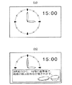
各画像表示端末11a〜11nには、液晶プロジェクター12a〜12nが設備され、スクリーン13a〜13nに時計画像により現在の時刻を表示するととともに、その他の文字情報や、静止画像や、動画像を表示する(図6を参照)。 Each of the image display terminals 11a to 11n is equipped with liquid crystal projectors 12a to 12n, and displays the current time as a clock image on the screens 13a to 13n, and displays other character information, still images, and moving images. (See FIG. 6).
また、各画像表示端末11a〜11nは、映像情報を提供するイベントエントリサーバ(映像情報送信装置)100とLAN(ローカルエリアネットワーク)などの通信ネットワーク20で通信接続され、イベントエントリサーバ100から画像情報を取得して、液晶プロジェクター12a〜12nによりスクリーン13a〜13nに画像を表示する。 The image display terminals 11 a to 11 n are connected to an event entry server (video information transmission device) 100 that provides video information via a communication network 20 such as a LAN (local area network). And images are displayed on the screens 13a to 13n by the liquid crystal projectors 12a to 12n.
また、通信ネットワーク20上にはネットワーク上の各機器に正確な時刻情報を提供するタイムサーバ30が設けられ、各画像表示端末11a〜11nおよびイベントエントリサーバ100は、このタイムサーバ30から時刻情報を取得し、システム全体が統一された時刻情報を基に運用される。
In addition, a
画像表示端末11a〜11nは、通常は、タイムサーバ30から取得した時刻情報を表示しており、例えば、図6(a)に示すような時計画像を、画像表示端末11a〜11n自身の処理機能により表示している。
The image display terminals 11a to 11n normally display time information acquired from the
また、各画像表示端末11a〜11nでは、タイムサーバ30から取得した時刻情報を基準にして、定期的(または、映像情報の表示後など非定期的)に、画像表示端末11a〜11n自身の「端末識別情報」をイベントエントリサーバ100に送信して、自身が表示すべき「映像情報」とその「表示時刻の情報」を要求する。
The image display terminals 11a to 11n are regularly (or non-periodically such as after video information is displayed) based on the time information acquired from the
イベントエントリサーバ100は、画像表示端末11a〜11nから「端末識別情報」を受信すると、「端末識別情報」を送信した画像表示端末11a〜11nが表示すべき「映像情報」を、画像表示端末11a〜11nに送信する。
When the
画像表示端末11a〜11nは、イベントエントリサーバ100から受信した「映像情報」を、表示開始刻になると、液晶プロジェクター12a〜12nとスクリーン13a〜13nにより表示する。この「映像情報」は、図6(b)に示すように、例えば、時計映像の上に上書きして、イベントの案内情報などが流される。そして、映像情報の表示後は、次に「映像情報」を表示するまでの間は、再び時計画像を表示する状態に戻る。
The image display terminals 11a to 11n display the “video information” received from the
このように、本発明においては、画像表示端末11a〜11nが自身が必要とする映像情報をイベントエントリサーバ100側に要求し、受信した映像情報を自身で表示する。
As described above, in the present invention, the image display terminals 11a to 11n request the video information required by the image display terminals 11a to 11n to the
すなわち、画像表示端末11a〜11nはプル型(画像表示端末11a〜11nからイベントエントリサーバ100にアクセスして情報を取得する方式)で映像情報を取得して自立的に表示を行うものであり、イベントエントリサーバ100から一方的に配信される画一的な情報ではなく、画像表示端末11a〜11n自身がその設置場所や時間帯に応じた情報をイベントエントリサーバ100から取得して提供するものである。例えば、デパートの紳士服売場では婦人服売場のバーゲンの案内は行わないなど、表示する情報を選択して売場の客層に合致した情報を提供することができる。
That is, the image display terminals 11a to 11n acquire video information in a pull type (a method of acquiring information by accessing the
また、時刻に会わせて、適宜にイベント情報などを順番に提供し、各階に客を誘導し、顧客が長くデパート内に留まるようにすることも可能となる。 It is also possible to provide event information and the like in order according to the time, guide customers to each floor, and allow customers to stay in the department store for a long time.
また、イベントエントリサーバ100側で、個々の画像表示端末11a〜11nへの映像情報の配信制御を常時行う必要がなくなり、イベントエントリサーバ100側での処理負担が軽減され、システム構成とその管理が容易となる。
Further, it is not necessary to always perform distribution control of video information to the individual image display terminals 11a to 11n on the
また、図2は、本発明の画像表示システムの機能構成例を示す図であり、イベントエントリサーバ100と画像表示端末200とが有する機能を示したものであり、本発明に直接関係する機能を示したものである。イベントエントリサーバ100内の端末識別情報受信機能101は、「映像情報」を要求する画像表示端末200からの「端末識別情報」を受信するための機能である。
FIG. 2 is a diagram showing an example of the functional configuration of the image display system of the present invention, showing the functions of the
映像情報抽出機能102は、画像表示端末200から受信した「端末識別情報」と「現在の時刻の情報」とを基に、データベース120内の表示開始テーブル121を参照して、当該端末が表示すべき「映像情報」と「表示開始時刻の情報」の情報を取得するための機能である。
Based on the “terminal identification information” and “current time information” received from the
表示情報送信機能103は、「映像情報」と「表示開始時刻の情報」を該当する画像表示端末200に送信するための機能である。
The display
なお、データベース120内の表示開始テーブル121は、図7の表示開始テーブルの例を示す図に例示するように、各画像表示端末200ごとに設けられるテーブルであり、端末識別IDごとに、「表示開始時刻」と「映像情報の識別情報」との対応関係がテーブルとして記録されたものである。イベントエントリサーバ100では、画像表示端末200からの端末識別情報を受信すると、この端末「識別情報」と「現在の時刻の情報」とを基にして、表示開始テーブル121を参照し、画像表示端末200の端末識別情報と現在の時刻から、映像情報の識別情報を取得し、該当する「映像情報」とその「表示開始時刻の情報」とを画像表示端末200に送信する。
The display start table 121 in the
また、画像表示端末200内の端末識別情報送信機能201は、画像表示端末200自身の識別情報をイベントエントリサーバ100に送信するための機能であり、この端末識別情報を送信することで、イベントエントリサーバ100に対して、「映像情報」と「表示開始時刻の情報」の送信を要求する。
The terminal identification
表示情報受信機能202は、イベントエントリサーバ100から「表示開始時刻の情報」と「映像情報」を受信するための機能であり、映像情報表示機能203は、イベントエントリサーバ100から受信した「映像情報」を、指定された表示開始時刻に液晶プロジェクター12とスクリーン13により表示するための機能である。
The display
時計画像表示機能204は、タイムサーバ30から取得した時刻情報を、時計画像により表示するための機能である(図6参照)。
The clock
また、記憶部220内には、画像表示端末自身の端末識別情報221と、イベントエントリサーバ100から受信した映像情報222が表示開始時刻の情報とともに記録される。
Further, in the
なお、タイムサーバ30内の時刻情報提供機能31は、画像表示端末200およびイベントエントリサーバ100に時刻情報を提供するための機能であり、画像表示端末200およびイベントエントリサーバ100は、このタイムサーバ30から定期的に時刻情報を取得して、自身の有する時計機能の校正を行う。
The time
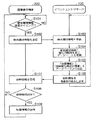
また、図3は、画像表示端末とイベントエントリサーバ間の処理シーケンスを示す図であり、画像表示端末200とイベントエントリサーバ100との間で行われる処理の流れを示したものである。なお、イベントエントリサーバ100および画像表示端末200は、それぞれタイムサーバ30から「時刻情報」を取得し、同じ時刻で同期し運用されるものとする。また、画像表示端末200は通常は時計画像により現時の時刻情報を表示しているものとする。
FIG. 3 is a diagram showing a processing sequence between the image display terminal and the event entry server, and shows a flow of processing performed between the
画像表示端末200は、定期的に自身の端末識別情報の送信タイミングが到来したかどうかを確認する(ステップS101)。送信タイミングが到来すると、画像表示端末200は、イベントエントリサーバ100に対して「端末識別情報」を送信する(ステップS102)。
The
イベントエントリサーバ100は、画像表示端末200から「端末識別情報」を受信すると(ステップS103)、この「端末識別情報」と「現在時刻の情報」を基に、データベース120を検索する(ステップS104)。例えば、図7に例示する表示開始テーブルを参照し、現在の時刻の次に表示すべき「映像情報」と「表示開始時刻の情報」を抽出する(ステップS105)。
When receiving the “terminal identification information” from the image display terminal 200 (step S103), the
それから、「映像情報」と「表示開始時刻の情報」を画像表示端末200に送信する(ステップS106)。画像表示端末200は、「映像情報」と「表示開始時刻の情報」を受信して記憶する(ステップS107)。
Then, “video information” and “display start time information” are transmitted to the image display terminal 200 (step S106). The
次に、画像表示端末200は、表示開始時刻が到来したかどうかを確認する(ステップS108)。表示開始時刻でない場合は、ステップS101に戻る。表示開始時刻になると、「映像情報」を表示する(ステップS109)。
Next, the
図4は従来のシステムとの比較を示す図である。この図が示すように、従来のシステムでは、(a)に示すように映像情報を絶え間なく表示端末に映像情報を流すには、管理者が常に映像情報の表示の管理をしなければ成らない。また(b)に示すように映像情報が短い場合には次の映像情報が始まるまで表示端末には何も表示されないような状況になる。また(c)に示すように表示時間の短い映像情報を詰めて、連続して表示できるように管理した場合でも、後の時間帯に何も表示されない時間ができてしまう為、その時間を穴埋めする為に別途映像情報を用意したり、既に表示した情報をもう一度表示するような管理を行なう必要がある。しかしながら、本発明のシステム(d)では、映像情報の表示時間が短くなって、次の映像情報の表示までの時間に時計を表示しておけるので、何も表示されていない状況を発生させることがない。そのため、従来に比べて、映像情報の変更や、管理を柔軟に行うことが出来る。 FIG. 4 is a diagram showing a comparison with a conventional system. As shown in this figure, in the conventional system, as shown in (a), in order to continuously send video information to the display terminal, the administrator must always manage the display of the video information. . Also, as shown in (b), when the video information is short, nothing is displayed on the display terminal until the next video information starts. Also, as shown in (c), even when video information with a short display time is packed and managed so that it can be continuously displayed, a time when nothing is displayed is created in the later time zone. In order to do this, it is necessary to prepare video information separately or perform management such that information already displayed is displayed again. However, in the system (d) of the present invention, the display time of the video information is shortened, and the clock can be displayed during the time until the display of the next video information, so that a situation where nothing is displayed is generated. There is no. Therefore, the video information can be changed and managed more flexibly than in the past.
また、図5は、画像表示端末200とイベントエントリサーバ100の構成例を示す図であり、本発明に直接関係する部分について示したものである。
FIG. 5 is a diagram showing a configuration example of the
図5に示すイベントエントリサーバ100において、105は通信ネットワーク20とサーバ100とを接続する通信用インタフェース、106はサーバ全体を制御する制御部、110は処理プログラム部、120はデータベースを示している。
In the
また、処理プログラム部110には、以下の処理部が含まれている。
端末識別情報受信処理部111は、「映像情報」を要求する画像表示端末200からの「端末識別情報」を受信するための処理部である。
The
The terminal identification information reception processing unit 111 is a processing unit for receiving “terminal identification information” from the
映像情報抽出処理部112は、端末の識別情報と現在の時刻の情報とを基に、データベース120内の表示開始テーブル121を参照して、当該端末が表示すべき「映像情報」と「表示開始時刻の情報」の情報を取得するための処理部である。
表示情報送信処理部113は、「映像情報」と「表示開始時刻の情報」を画像表示端末200に送信するための処理部である。
時刻情報取得処理部114は、タイムサーバ30から定期的に時刻情報を取得するための処理部であり、画像表示端末200における映像情報の表示などは、この時刻情報を基準にして行われる。
The video information
The display information transmission processing unit 113 is a processing unit for transmitting “video information” and “display start time information” to the
The time information acquisition processing unit 114 is a processing unit for periodically acquiring time information from the
なお、データベース120内の表示開始テーブル121には、図7の表示開始テーブルの例を示す図に例示するように、各画像表示端末200ごとに設けられるテーブルであり、端末識別IDごとに、「表示開始時刻」と「映像情報の識別情報」との対応関係を記録したテーブルである。また、映像情報122は、画像表示端末200に配信する静止画、動画、テキストなどの映像情報である。
The display start table 121 in the
また、画像表示端末200において、205は画像表示端末200の全体を制御する制御部、206は通信ネットワーク20と画像表示端末200とを通信接続する通信用インタフェース、210は処理プログラム部、220は記憶部を示している。
In the
また、処理プログラム部210内の端末識別情報送信処理部211は、画像表示端末200自身の識別情報をイベントエントリサーバ100に送信するための処理部であり、この端末識別情報を送信することで、イベントエントリサーバ100に対して、「映像情報」と「表示開始時刻の情報」の送信を要求する。
The terminal identification information transmission processing unit 211 in the
表示情報受信処理部212は、イベントエントリサーバ100から「表示開始時刻の情報」と「映像情報」を受信するための機能である。映像情報表示処理部213は、イベントエントリサーバ100から受信した「映像情報」を、液晶プロジェクター12とスクリーン13により指定された表示開始時刻に表示するための処理部である。
The display information reception processing unit 212 is a function for receiving “display start time information” and “video information” from the
時刻情報取得処理部214は、タイムサーバ30から定期的に時刻情報を取得するための処理部であり、画像表示端末200における映像情報の表示などは、この時刻情報を基準にして行われる。時計画像表示処理部215は、タイムサーバ30から取得した時刻情報を、時計画像により表示するための処理部である(図6参照)。
The time information acquisition processing unit 214 is a processing unit for periodically acquiring time information from the
また、記憶部220内には、画像表示端末自身の端末識別情報221と、イベントエントリサーバ100から受信した映像情報222が表示開始時刻の情報とともに記録される。
Further, in the
なお、図5に示すイベントエントリサーバ100内の処理プログラム部110、および画像表示端末200内の処理プログラム部210は専用のハードウエアにより実現されるものであってもよく、またこの処理プログラム部はメモリおよびCPU(中央処理装置)により構成され、この処理部の機能を実現するためのプログラム(図示せず)をメモリにロードして実行することによりその機能を実現させるものであってもよい。また、イベントエントリサーバ100には、周辺機器として入力装置、表示装置等(いずれも表示せず)が接続されているものとする。ここで、入力装置としては、キーボード、マウス等の入力デバイスのことをいう。表示装置とは、CRT(Cathode Ray Tube)や液晶表示装置等のことをいう。
Note that the
また、図5に示すイベントエントリサーバ100内の処理プログラム部110、および画像表示端末200内の処理プログラム部210の機能を実現するためのプログラムをコンピュータ読み取り可能な記録媒体に記録して、この記録媒体に記録されたプログラムをコンピュータシステムに読み込ませ、実行することにより、図5に示すイベントエントリサーバ100内の処理プログラム部110、および画像表示端末200内の処理プログラム部210に必要な処理を行ってもよい。なお、ここでいう「コンピュータシステム」とは、OSや周辺機器等のハードウェアを含むものとする。
Further, a program for realizing the functions of the
また、「コンピュータ読み取り可能な記録媒体」とは、フレキシブルディスク、光磁気ディスク、ROM、CD−ROM等の可搬媒体、コンピュータシステムに内蔵されるハードディスク等の記憶装置のことをいう。さらに「コンピュータ読み取り可能な記録媒体」とは、インターネット等のネットワークや電話回線等の通信回線を介してプログラムを送信する場合の通信線のように、短時間の間、動的にプログラムを保持するもの(伝送媒体ないしは伝送波)、その場合のサーバやクライアントとなるコンピュータシステム内部の揮発性メモリのように、一定時間プログラムを保持しているものも含むものとする。
また上記プログラムは、前述した機能の一部を実現するためのものであっても良く、さらに前述した機能をコンピュータシステムにすでに記録されているプログラムとの組み合わせで実現できるもの、いわゆる差分ファイル(差分プログラム)であっても良い。
The “computer-readable recording medium” refers to a portable medium such as a flexible disk, a magneto-optical disk, a ROM, and a CD-ROM, and a storage device such as a hard disk built in the computer system. Furthermore, the “computer-readable recording medium” dynamically holds a program for a short time like a communication line when transmitting a program via a network such as the Internet or a communication line such as a telephone line. It also includes a device (transmission medium or transmission wave) and a device that holds a program for a certain period of time, such as a volatile memory inside a computer system serving as a server or client in that case.
The program may be for realizing a part of the functions described above, and further, a program that can realize the functions described above in combination with a program already recorded in a computer system, a so-called difference file (difference). Program).
以上、本発明の実施の形態について説明したが、本発明の画像表示システムは、上述の図示例にのみ限定されるものではなく、本発明の要旨を逸脱しない範囲内において種々変更を加え得ることは勿論である。 Although the embodiments of the present invention have been described above, the image display system of the present invention is not limited to the above-described illustrated examples, and various modifications can be made without departing from the scope of the present invention. Of course.
本発明においては、画像表示装置がサーバからプル型で映像情報を取得して自立的に表
示を行おこなうため、各設置場所ごとに必要な情報を容易に提供することができる効果を
奏するので、本発明は、画像表示装置、及び画像表示方法などに適用できる。
In the present invention, since an effect of the image display device can easily provide the necessary information for each order, each location having performed row autonomously acquires and displays video information pull from the server The present invention can be applied to an image display device, an image display method, and the like.
11a〜11n…画像表示端末,12、12a〜12n…液晶プロジェクター,13、13a〜13n…スクリーン,20…通信ネットワーク,30…タイムサーバ,31…時刻情報提供機能,100…イベントエントリサーバ,101…端末識別情報受信機能,102…映像情報抽出機能,103…表示情報送信機能,110…処理プログラム部,111…端末識別情報受信処理部,112…映像情報抽出処理部,113…表示情報送信処理部,114…時刻情報取得処理部,120…データベース,121…表示開始テーブル,122…映像情報,200…画像表示端末,201…端末識別情報送信機能,202…表示情報受信機能,203…映像情報表示機能,204…時計画像表示機能,210…処理プログラム部,211…端末識別情報送信処理部,212…表示情報受信処理部213…映像情報表示処理部,214…時刻情報取得処理部,215…時計画像表示処理部,220…記憶部,221…端末識別情報,222…映像情報
11a to 11n, image display terminals, 12, 12a to 12n, liquid crystal projector, 13, 13a to 13n, screen, 20 ... communication network, 30 ... time server, 31 ... time information providing function, 100 ... event entry server, 101 ... Terminal identification information reception function, 102 ... Video information extraction function, 103 ... Display information transmission function, 110 ... Processing program section, 111 ... Terminal identification information reception processing section, 112 ... Video information extraction processing section, 113 ... Display information transmission processing section , 114 ... Time information acquisition processing unit, 120 ... Database, 121 ... Display start table, 122 ... Video information, 200 ... Image display terminal, 201 ... Terminal identification information transmission function, 202 ... Display information reception function, 203 ... Video information display Function 204: Clock
Claims (3)
ークを介して接続された画像表示システムであって、
前記映像情報送信装置は、
前記画像表示装置に送信する映像情報が予め記憶された映像情報記憶手段と、
前記画像表示装置の端末識別情報に対して、前記画像表示装置が表示すべき映像情報の
識別情報と表示開始時刻の情報とを関連づけて記憶する表示開始テーブル記憶手段と、
前記画像表示装置から前記端末識別情報を受信した場合に、前記端末識別情報と現在の
時刻を基に前記表示開始テーブルを参照し、前記画像表示装置が表示すべき映像情報の識
別情報と表示開始時刻の情報とを抽出する映像情報抽出手段と、
前記映像情報抽出手段により抽出された前記映像情報の識別情報を持つ前記映像情報を
前記映像情報記憶手段から読み出し、読み出した前記映像情報と前記表示開始時刻の情報
とを前記画像表示装置に送信する表示情報送信手段とを備え、
前記画像表示装置は、
計時手段と、
受信した前記映像情報を記憶する記憶手段と、
前記画像表示装置の端末識別情報を定期的に前記映像情報送信装置に送信する端末識別
情報送信手段と、
前記映像情報送信装置が送信した前記映像情報と前記表示開始時刻の情報とを受信して
前記記憶手段に記憶する受信手段と、
前記計時手段を参照して、前記映像情報送信装置から受信した前記表示開始時刻が到来
したか否かを判定し、前記表示開始時刻が到来した場合に、前記記憶手段に記憶した映像
情報を読み出して表示する映像表示手段と
を備えることを特徴とする画像表示システム。 An image display system and the video information transmitting apparatus are connected via a network for transmitting video information to the image display device and the front Kiga image display device,
The video information transmitting device is
Video information storage means for image information is stored in advance to be transmitted before Kiga image display device,
The video information to be displayed by the image display device with respect to the terminal identification information of the image display device .
Display start table storage means for storing the identification information and the display start time information in association with each other;
When receiving the image display device or et previous SL terminal identification information, identification of the terminal identification information and the current time with reference to the display start table based video information the image display device to be displayed
Video information extraction means for extracting the separate information and the display start time information;
The video information having identification information of the video information extracted by the video information extracting means
Display information transmitting means for reading from the video information storage means, and transmitting the read video information and the display start time information to the image display device;
The image display device includes:
Timekeeping means,
Storage means for storing the received video information;
Terminal identification information transmitting means for periodically transmitting terminal identification information of the image display device to the video information transmitting device;
Receiving the video information and the display start time information transmitted by the video information transmitting device;
Receiving means for storing in the storage means;
With reference to the clock means, the display start time received from the image information transmitting apparatus arrives
And an image display means for reading out and displaying the image information stored in the storage means when the display start time has arrived .
する請求項1に記載の画像表示システム。 The image display system according to claim 1, wherein the image display device displays a clock image while the video information is not displayed.
記映像情報と前記時計画像を重ねて表示することを特徴とする請求項2に記載の画像表示
システム。 The image display equipment, when the clock image always displayed, displaying the video information, prior to
The image display system according to claim 2, wherein the video information and the clock image are displayed in an overlapping manner .
Priority Applications (1)
| Application Number | Priority Date | Filing Date | Title |
|---|---|---|---|
| JP2003403004A JP4259298B2 (en) | 2003-12-02 | 2003-12-02 | Image display system and image display method |
Applications Claiming Priority (1)
| Application Number | Priority Date | Filing Date | Title |
|---|---|---|---|
| JP2003403004A JP4259298B2 (en) | 2003-12-02 | 2003-12-02 | Image display system and image display method |
Publications (3)
| Publication Number | Publication Date |
|---|---|
| JP2005167573A JP2005167573A (en) | 2005-06-23 |
| JP2005167573A5 JP2005167573A5 (en) | 2006-09-07 |
| JP4259298B2 true JP4259298B2 (en) | 2009-04-30 |
Family
ID=34726437
Family Applications (1)
| Application Number | Title | Priority Date | Filing Date |
|---|---|---|---|
| JP2003403004A Expired - Lifetime JP4259298B2 (en) | 2003-12-02 | 2003-12-02 | Image display system and image display method |
Country Status (1)
| Country | Link |
|---|---|
| JP (1) | JP4259298B2 (en) |
Cited By (1)
| Publication number | Priority date | Publication date | Assignee | Title |
|---|---|---|---|---|
| CN103648059A (en) * | 2013-11-19 | 2014-03-19 | 乐视网信息技术(北京)股份有限公司 | Advertisement broadcasting method and apparatus |
Families Citing this family (5)
| Publication number | Priority date | Publication date | Assignee | Title |
|---|---|---|---|---|
| JP4893356B2 (en) * | 2007-02-16 | 2012-03-07 | 株式会社Jvcケンウッド | Network image transmission display method |
| JP5836746B2 (en) * | 2011-10-20 | 2015-12-24 | 三菱電機株式会社 | Display terminal |
| CN102868922B (en) * | 2012-09-11 | 2016-08-10 | Tcl通力电子(惠州)有限公司 | Method and system for playing advertisement |
| JP6422233B2 (en) * | 2014-04-30 | 2018-11-14 | 株式会社Tbグループ | Display management system |
| JP7137173B2 (en) * | 2016-12-08 | 2022-09-14 | チームラボ株式会社 | COLLECTION SYSTEM, TERMINAL PROGRAM AND COLLECTION METHOD |
Family Cites Families (1)
| Publication number | Priority date | Publication date | Assignee | Title |
|---|---|---|---|---|
| JP2002044627A (en) * | 2000-07-26 | 2002-02-08 | Seiko Epson Corp | Projector |
-
2003
- 2003-12-02 JP JP2003403004A patent/JP4259298B2/en not_active Expired - Lifetime
Cited By (1)
| Publication number | Priority date | Publication date | Assignee | Title |
|---|---|---|---|---|
| CN103648059A (en) * | 2013-11-19 | 2014-03-19 | 乐视网信息技术(北京)股份有限公司 | Advertisement broadcasting method and apparatus |
Also Published As
| Publication number | Publication date |
|---|---|
| JP2005167573A (en) | 2005-06-23 |
Similar Documents
| Publication | Publication Date | Title |
|---|---|---|
| US7038637B1 (en) | System and method for selling advertising space on electronic billboards over the internet | |
| US9785924B2 (en) | System, software application, and method for displaying third party media content in a public space | |
| US20040015401A1 (en) | Systems and methods for distributing template-based multimedia presentations over a network | |
| CN100999296A (en) | Information display system for elevators | |
| US20040212548A1 (en) | Method and system for displaying advertising on an electronic display screen | |
| US20150088621A1 (en) | Input device, signage server, and input method | |
| KR102236285B1 (en) | Driving method and integrated solution system using a outdoor advertising and signage based on big data | |
| US20050261928A1 (en) | System and method for managing content displayed on a distributed network of signs | |
| JP5885334B2 (en) | Advertisement distribution apparatus and program | |
| JP4259298B2 (en) | Image display system and image display method | |
| KR20210105049A (en) | Shop Information Service Supply System | |
| JP7458589B2 (en) | Information provision system and information provision method | |
| JP2009080717A (en) | System, apparatus, method, and program for content distribution | |
| JP2016170822A (en) | Distribution device, distribution method, and program | |
| JP2002328638A (en) | Advertisement information providing system | |
| KR102324135B1 (en) | Advertising mediation platform system using extended contents | |
| KR20010000758A (en) | System for advertising according to user's order based on internet | |
| JP6717397B2 (en) | Information distribution system, information distribution device and program | |
| KR20000049922A (en) | Multimedia Information Terminal System(MITS) and it's Operating System implemented on Web | |
| EP1708457A1 (en) | Information providing system and method therefor | |
| KR20050050379A (en) | System for providing advertisement | |
| KR20120004875A (en) | Method of providing competitive tender service based on for advertising agency and system thereof | |
| JP2008233233A (en) | Electronic advertisement system | |
| JP2014160480A (en) | Advertisement distribution system, store-side terminal device, and program | |
| JP2001312444A (en) | Method and system for information distribution |
Legal Events
| Date | Code | Title | Description |
|---|---|---|---|
| A521 | Request for written amendment filed |
Free format text: JAPANESE INTERMEDIATE CODE: A523 Effective date: 20060725 |
|
| A621 | Written request for application examination |
Free format text: JAPANESE INTERMEDIATE CODE: A621 Effective date: 20060725 |
|
| RD04 | Notification of resignation of power of attorney |
Free format text: JAPANESE INTERMEDIATE CODE: A7424 Effective date: 20070403 |
|
| A977 | Report on retrieval |
Free format text: JAPANESE INTERMEDIATE CODE: A971007 Effective date: 20080515 |
|
| A131 | Notification of reasons for refusal |
Free format text: JAPANESE INTERMEDIATE CODE: A131 Effective date: 20080527 |
|
| A521 | Request for written amendment filed |
Free format text: JAPANESE INTERMEDIATE CODE: A523 Effective date: 20080718 |
|
| TRDD | Decision of grant or rejection written | ||
| A01 | Written decision to grant a patent or to grant a registration (utility model) |
Free format text: JAPANESE INTERMEDIATE CODE: A01 Effective date: 20090120 |
|
| A01 | Written decision to grant a patent or to grant a registration (utility model) |
Free format text: JAPANESE INTERMEDIATE CODE: A01 |
|
| A61 | First payment of annual fees (during grant procedure) |
Free format text: JAPANESE INTERMEDIATE CODE: A61 Effective date: 20090202 |
|
| FPAY | Renewal fee payment (event date is renewal date of database) |
Free format text: PAYMENT UNTIL: 20120220 Year of fee payment: 3 |
|
| R150 | Certificate of patent or registration of utility model |
Ref document number: 4259298 Country of ref document: JP Free format text: JAPANESE INTERMEDIATE CODE: R150 Free format text: JAPANESE INTERMEDIATE CODE: R150 |
|
| FPAY | Renewal fee payment (event date is renewal date of database) |
Free format text: PAYMENT UNTIL: 20130220 Year of fee payment: 4 |
|
| FPAY | Renewal fee payment (event date is renewal date of database) |
Free format text: PAYMENT UNTIL: 20130220 Year of fee payment: 4 |
|
| S531 | Written request for registration of change of domicile |
Free format text: JAPANESE INTERMEDIATE CODE: R313531 |
|
| R350 | Written notification of registration of transfer |
Free format text: JAPANESE INTERMEDIATE CODE: R350 |
|
| EXPY | Cancellation because of completion of term |