JP4256031B2 - Processing apparatus and temperature control method thereof - Google Patents
Processing apparatus and temperature control method thereof Download PDFInfo
- Publication number
- JP4256031B2 JP4256031B2 JP21204899A JP21204899A JP4256031B2 JP 4256031 B2 JP4256031 B2 JP 4256031B2 JP 21204899 A JP21204899 A JP 21204899A JP 21204899 A JP21204899 A JP 21204899A JP 4256031 B2 JP4256031 B2 JP 4256031B2
- Authority
- JP
- Japan
- Prior art keywords
- temperature
- refrigerant
- difference value
- processed
- control
- Prior art date
- Legal status (The legal status is an assumption and is not a legal conclusion. Google has not performed a legal analysis and makes no representation as to the accuracy of the status listed.)
- Expired - Lifetime
Links
- 238000000034 method Methods 0.000 title claims description 29
- 239000003507 refrigerant Substances 0.000 claims description 110
- 239000002826 coolant Substances 0.000 claims description 13
- 239000000498 cooling water Substances 0.000 description 52
- 235000012431 wafers Nutrition 0.000 description 19
- 238000001816 cooling Methods 0.000 description 14
- 238000005530 etching Methods 0.000 description 11
- 238000001514 detection method Methods 0.000 description 5
- 238000001020 plasma etching Methods 0.000 description 3
- 238000005086 pumping Methods 0.000 description 3
- 239000004065 semiconductor Substances 0.000 description 3
- 230000007423 decrease Effects 0.000 description 2
- 238000012986 modification Methods 0.000 description 2
- 230000004048 modification Effects 0.000 description 2
- 239000000758 substrate Substances 0.000 description 2
- 230000000694 effects Effects 0.000 description 1
- 239000011521 glass Substances 0.000 description 1
- 238000010438 heat treatment Methods 0.000 description 1
- 238000004519 manufacturing process Methods 0.000 description 1
- 230000004043 responsiveness Effects 0.000 description 1
- 229920006395 saturated elastomer Polymers 0.000 description 1
Images

Classifications
-
- H—ELECTRICITY
- H01—ELECTRIC ELEMENTS
- H01L—SEMICONDUCTOR DEVICES NOT COVERED BY CLASS H10
- H01L21/00—Processes or apparatus adapted for the manufacture or treatment of semiconductor or solid state devices or of parts thereof
- H01L21/67—Apparatus specially adapted for handling semiconductor or electric solid state devices during manufacture or treatment thereof; Apparatus specially adapted for handling wafers during manufacture or treatment of semiconductor or electric solid state devices or components ; Apparatus not specifically provided for elsewhere
- H01L21/67005—Apparatus not specifically provided for elsewhere
- H01L21/67242—Apparatus for monitoring, sorting or marking
- H01L21/67248—Temperature monitoring
-
- H—ELECTRICITY
- H01—ELECTRIC ELEMENTS
- H01L—SEMICONDUCTOR DEVICES NOT COVERED BY CLASS H10
- H01L21/00—Processes or apparatus adapted for the manufacture or treatment of semiconductor or solid state devices or of parts thereof
- H01L21/02—Manufacture or treatment of semiconductor devices or of parts thereof
- H01L21/04—Manufacture or treatment of semiconductor devices or of parts thereof the devices having potential barriers, e.g. a PN junction, depletion layer or carrier concentration layer
- H01L21/18—Manufacture or treatment of semiconductor devices or of parts thereof the devices having potential barriers, e.g. a PN junction, depletion layer or carrier concentration layer the devices having semiconductor bodies comprising elements of Group IV of the Periodic Table or AIIIBV compounds with or without impurities, e.g. doping materials
- H01L21/30—Treatment of semiconductor bodies using processes or apparatus not provided for in groups H01L21/20 - H01L21/26
- H01L21/302—Treatment of semiconductor bodies using processes or apparatus not provided for in groups H01L21/20 - H01L21/26 to change their surface-physical characteristics or shape, e.g. etching, polishing, cutting
- H01L21/306—Chemical or electrical treatment, e.g. electrolytic etching
- H01L21/3065—Plasma etching; Reactive-ion etching
-
- H—ELECTRICITY
- H01—ELECTRIC ELEMENTS
- H01L—SEMICONDUCTOR DEVICES NOT COVERED BY CLASS H10
- H01L21/00—Processes or apparatus adapted for the manufacture or treatment of semiconductor or solid state devices or of parts thereof
- H01L21/67—Apparatus specially adapted for handling semiconductor or electric solid state devices during manufacture or treatment thereof; Apparatus specially adapted for handling wafers during manufacture or treatment of semiconductor or electric solid state devices or components ; Apparatus not specifically provided for elsewhere
- H01L21/67005—Apparatus not specifically provided for elsewhere
- H01L21/67011—Apparatus for manufacture or treatment
- H01L21/67098—Apparatus for thermal treatment
- H01L21/67109—Apparatus for thermal treatment mainly by convection
-
- H—ELECTRICITY
- H01—ELECTRIC ELEMENTS
- H01J—ELECTRIC DISCHARGE TUBES OR DISCHARGE LAMPS
- H01J2237/00—Discharge tubes exposing object to beam, e.g. for analysis treatment, etching, imaging
- H01J2237/20—Positioning, supporting, modifying or maintaining the physical state of objects being observed or treated
- H01J2237/2001—Maintaining constant desired temperature
-
- H—ELECTRICITY
- H01—ELECTRIC ELEMENTS
- H01J—ELECTRIC DISCHARGE TUBES OR DISCHARGE LAMPS
- H01J2237/00—Discharge tubes exposing object to beam, e.g. for analysis treatment, etching, imaging
- H01J2237/32—Processing objects by plasma generation
Landscapes
- Engineering & Computer Science (AREA)
- Physics & Mathematics (AREA)
- Condensed Matter Physics & Semiconductors (AREA)
- General Physics & Mathematics (AREA)
- Manufacturing & Machinery (AREA)
- Computer Hardware Design (AREA)
- Microelectronics & Electronic Packaging (AREA)
- Power Engineering (AREA)
- Plasma & Fusion (AREA)
- Drying Of Semiconductors (AREA)
- Control Of Temperature (AREA)
Description
【0001】
【発明の属する技術分野】
本発明は,処理装置およびその温度制御方法に関する。
【0002】
【従来の技術】
従来,半導体装置やLCD基板などの製造工程においては,プラズマエッチング装置などの各種処理装置が使用されている。例えば,プラズマエッチング装置は,真空処理室内において所定の処理ガスをプラズマ化し,載置台上に載置された半導体ウェハやガラス基板などの被処理体に対してエッチング処理を施すものである。そして,処理にあたっては,プラズマによる被処理体の温度上昇を抑えたり,あるいは,エッチングのアスペクト比を高めたり,エッチング形状を整えたりするために,被処理体を所定温度に維持している。
【0003】
被処理体の温度管理は,一般に,載置台に設けられた冷却機構により行われている。かかる冷却機構は,冷媒を載置台内に巡らされた冷媒循環路に送り込み,その冷媒が熱を吸収することにより被処理体を冷却する構成を採用している。そして,冷却回路により温調された冷媒タンク内の冷媒はポンプにより冷媒循環路に送り込まれ,冷媒循環路から戻された冷媒は冷却回路により温調され冷媒タンクに送り込まれる。そして,冷媒タンク内あるいは冷媒タンクから冷媒循環路に送り込まれる冷媒の温度を監視して,その温度が所定温度になるように温度制御を行っている。
【0004】
【発明が解決しようとする課題】
しかしながら,冷媒の温度は,被処理体に負荷される熱量,すなわち冷媒循環路内の冷媒が吸収する熱量とは無関係に制御されているので,プラズマ処理によって被処理体に加わる熱量が増加すると,熱容量が飽和するまで被処理体の温度が上昇してしまい,その結果,被処理体に均一な処理を施せないという問題点がある。
【0005】
本発明は,従来の技術が有する上記問題点に鑑みて成されたものであり,本発明の目的は,上記問題点およびその他の問題点を解決することが可能な,新規かつ改良された処理装置およびその温度制御方法を提供することである。
【0006】
【課題を解決するための手段】
上記課題を解決するために,本発明の第1の観点によれば,冷媒循環路を備えた載置台を処理室内に有するとともに,冷媒循環路を循環する冷媒の熱量制御および/または流量制御を行う温調回路を備えた処理装置の温度制御方法であって,冷媒循環路の入口温度と出口温度の実測差分値に基づいて,冷媒の熱量制御および/または流量制御を行うことにより,載置台の温度制御を行うことを特徴とする処理装置の温度制御方法が提供される。
【0007】
本発明によれば,冷媒循環路内で熱を吸収した冷媒の温度である出口温度から熱を吸収する前の冷媒の温度である入口温度を減算して,冷媒が載置台を介して被処理体から奪った熱の熱量値である実測差分値を算出することができ,該実測差分値に基づく冷媒の熱量制御や流量制御を行うことができる。その結果,処理時に被処理体に加わる熱量が変化しても,該熱量変化に応じて被処理体が一定温度に保たれるように冷媒の温度制御を行うことができるので,被処理体の温度管理を的確に行え,被処理体に均一な処理を施すことができる。
【0008】
また,例えば,処理に応じて,冷媒循環路の入口温度と出口温度との目標差分値を予め決定し,実測差分値が目標差分値に追随するように冷媒の熱量制御および/または流量制御を行うことが好ましい。かかる構成によれば,予め各プロセスに応じた理想的な入口温度と出口温度との差である目標差分値を設定し,実測差分値が目標差分値と実質的に同一になるように冷媒の温度制御を行えるので,被処理体の温度管理をプロセスに応じて的確に行うことができる。
【0009】
さらに,例えば,処理に応じて,目標差分値と温調回路への冷媒の目標戻り温度との関係を予め決定し,温調回路への冷媒の実測戻り温度が目標戻り温度に追随するように冷媒の熱量制御および/または流量制御を行うことが好ましい。かかる構成によれば,目標差分値と目標戻り温度との関係を,例えば被処理体の設定温度から目標差分値を減算した値と目標戻り温度とが同一になる関係とすれば,実測戻り温度が目標戻り温度に追従するように冷媒の熱量制御や流量制御を行うことにより,処理時の熱量変化に応じた冷媒の温度制御を確実に行うことができる。この際,さらに上記実測差分値が目標差分値に追従するようにフィードバックをかけながら冷媒の熱量あるいは流量制御を行えば,被処理体の温度管理をより厳密に行うことができる。
【0010】
また,例えば,処理に応じて,目標差分値と温調回路からの冷媒の目標送り温度との関係を予め決定し,温調回路からの冷媒の実測送り温度が目標送り温度に追随するように冷媒の熱量制御および/または流量制御を行っても,被処理体の温度管理を厳密に行うことができる。
【0011】
また,温調回路を構成するポンプなどの駆動手段をきめ細かく制御して冷媒の熱量制御や流量制御を安定して行い,かつ駆動手段のオン・オフに伴う突入電流の発生などを防止して消費電力の軽減を図るためには,例えば,温調回路をインバータ制御することが好ましい。
【0012】
また,本発明の第2の観点によれば,処理室内にて被処理体を載置する載置台と,載置台に設けられた冷媒循環路と,冷媒循環路を循環する冷媒の熱量制御および/または流量制御を行う温調回路とを備えた処理装置において,冷媒循環路の入口温度を検出する入口温度検出手段と,冷媒循環路の出口温度を検出する出口温度検出手段と,冷媒循環路の入口温度と出口温度との実測差分値に基づいて温調回路を制御する制御手段とを備えたことを特徴とする処理装置が提供される。
【0013】
本発明によれば,入口温度検出手段と出口温度検出手段により冷媒循環路内で熱を吸収する前後の冷媒の温度である入口温度と出口温度とを求め,制御手段により出口温度から入口温度を減算して求められる冷媒が吸収した熱の熱量値である実測差分値に基づいて冷媒の熱量制御や流量制御を行うことができる。その結果,処理時の被処理体の熱量変化に応じて冷媒の温度制御を行えるので,被処理体の温度管理を的確に行うことができる。
【0014】
また,被処理体の温度管理をより厳密に行うためには,例えば,さらに温調回路への冷媒の戻り温度を検出する戻り温度検出手段を備えて,制御手段により実測差分値に基づいて冷媒の戻り温度を制御したり,あるいは,さらに温調回路からの冷媒の送り温度を検出する送り温度検出手段を備えて,制御手段により実測差分値に基づいて冷媒の送り温度を制御することが好ましい。
【0015】
【発明の実施の形態】
以下に,添付図面を参照しながら,本発明にかかる処理装置およびその温度制御方法を,プラズマエッチング装置およびその温度制御方法に適用した好適な実施の一形態について詳細に説明する。
【0016】
(1)エッチング装置の全体構成
まず,エッチング装置100の構成について概略すると,図1に示すように,気密な処理容器102内に形成された処理室104内には,被処理体,例えば半導体ウェハ(以下,「ウェハ」と称する。)Wを載置可能な載置台としての下部電極106が配置されている。下部電極106には,下部電極106を介してウェハWを冷却して所定温度に維持するための冷媒循環路108が内装されている。冷媒循環路108には,後述の如く温調された冷媒としての第1冷却水CW1を冷媒循環路108内に供給するとともに,冷媒循環路108内を循環した第1冷却水CW1を回収して再び温調する本発明の中核を成す温調回路としての冷却回路110が接続されている。なお,冷却回路110の構成および第1冷却水CW1の温度制御については,以下で詳述する。
【0017】
また,処理室104内には,下部電極106の載置面に対向して上部電極112が配置されている。かかる構成により,高周波電源114から出力された高周波電力を整合器116を介して下部電極106に印加すると,処理ガス供給源G118から流量調整バルブMFC120と上部電極112に形成された多数のガス吐出孔112aとを介して処理室104内に導入された処理ガスがプラズマ化し,下部電極106上で所定温度に維持されたウェハWにエッチング処理が施される。また,処理室104内のガスは,排気系122から排気される。
【0018】
(2)冷却機構の構成
次に,本発明の中核を成す冷却回路110について詳述する。冷却回路110を構成する冷媒タンク124内には,後述の如く温調された第1冷却水CW1が蓄えられている。また,冷媒タンク124内には,第1冷却水CW1の加熱するためのヒータ126が設けられている。冷媒タンク124内の第1冷却水CW1は,本実施の形態にかかる第1インバータ回路128によりインバータ制御される第1循環ポンプ130により加圧され,冷媒供給経路132を介して下部電極106内の冷媒循環路108に送り出される。かかる構成によれば,第1インバータ回路128が供給電力の周波数制御を行い,第1循環ポンプ130を駆動するモータの回転数を適宜調整できるので,設定条件に応じた一定流量の第1冷却水CW1を冷媒循環路108と冷却回路110との間で循環させることができる。その結果,後述する第1冷却水CW1の温度制御を容易かつ正確に行うことができる。また,第1循環ポンプ130の揚水量は,制御器134が第1インバータ回路128を制御することにより,適宜調整される。
【0019】
また,冷媒循環路108内を循環した第1冷却水CW1は,冷媒排出管136を介して冷却回路110に戻され,冷却器138で所定温度に温調された後,再び冷媒タンク124内に蓄えられる。冷却器138は,冷媒排出管136に介装され第1冷却水CW1を冷却する第1熱交換器140,第1冷却水CW1よりも低い温度の第2冷却水CW2が循環する第2熱交換器142,第1および第2熱交換器140,142内を通って第1および第2熱交換器140,142間で熱の受け渡しを行う第3冷却水CW3を循環させる熱交換路144から構成されている。また,熱交換路144には,第2インバータ回路146によりインバータ制御される第2循環ポンプ148と,開閉バルブ150が介装されている。
【0020】
従って,制御器134の命令によって第2インバータ回路146が第2循環ポンプ148の揚水量を調整し,第2熱交換器142内で冷却された所定流量の第3冷却水CW3を熱交換路144内で循環させることにより,第1熱交換器140内の通過時に第1冷却水CW1の熱が吸収されて,第1冷却水CW1が所定温度に温調される。また,第1冷却水CW1の温度は,制御器134の命令により第2循環ポンプ148の揚水量を調整すれば適宜変更可能であり,第3冷却水CW3の流量を増やせば下がり,逆に流量を減らせば上がる。
【0021】
かかる構成によれば,第1冷却水CW1の流量を変化させないで,第1冷却水CW1の温調を行うことができる。その結果,第1冷却水CW1の流量を一定に維持できるので,後述の第1冷却水CW1の温度制御に用いる演算を的確に行うことができる。また,第2循環ポンプ148は,インバータ制御されるので,第3冷却水CW3の迅速な流量制御により第1冷却水CW1の温度制御の応答性を向上でき,さらに第3冷却水CW3の効率的な流量調整により消費電力の軽減を図ることができる。
【0022】
また,冷媒供給管132と冷媒排出管136には,それぞれに対応して,本実施の形態にかかる送り温度検出手段としての第1温度センサTh1および入口温度検出手段としての第2温度センサTh2と,出口温度検出手段としての第3温度センサTh3および戻り温度検出手段としての第4温度センサTh4が介装されている。第1温度センサTh1は冷媒タンク124から送り出された直後の第1冷却水CW1の実測送り温度を検出し,第4温度センサTh4は第1熱交換器140内に戻される直前の第1冷却水CW1の実測戻り温度を検出する。また,第2温度センサTh2は冷媒循環路108内に供給される直前の第1冷却水CW1の実測入口温度を検出し,第3温度センサTh3は冷媒循環路108から排出された直後の第1冷却水CW1の実測出口温度を検出する。また,第1〜第4温度センサTh1〜Th4で検出された各温度情報は,制御器134に伝達され,後述する第1冷却水CW1の温度制御に用いられる。
【0023】
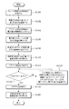
(3)ウェハWの温度制御
次に,ウェハWの温度制御について,図2に示すフローチャートを参照しながら説明する。まず,処理開始前に,処理時のウェハWの温度Ts,例えば−10℃を制御器134に設定する(ステップS100)。その後,制御器134は,第1温度センサTh1で検出される実測送り温度が設定温度Tsの−10℃になるように,冷却器138を制御して第1冷却水CW1を温調する(ステップS102)。以下,後述するステップS108までのプラズマ処理前は,第1温度センサTh1の検出温度に基づいて第1冷却水CW1の温調が行われる。
【0024】
次いで,処理時に下部電極106に印加する予定の高周波の電力値を制御器134に設定する(ステップS104)。制御器134は,上記電力値に基づいて,予め求めておいた熱量算出用の一次近似式から処理時にウェハWに負荷される熱量Qを算出する(ステップS106)。上記一次近似式は,熱量Qが処理装置のプラズマソースごとに異なるために,各プラズマソースごとに予め実験的に求めた電力値と熱量との関係から求める。
【0025】
さらに,制御器134は,上記算出された熱量Qに基づいて下記の式(1)
ΔT=Q/g×Cp×ρ …(1)
から冷媒循環路108の入口温度と出口温度との理論的な温度差である目標差分値ΔTを算出し,設定する(ステップS108)。目標差分値ΔTは,後述するプラズマ処理時の第1冷却水CW1の温度制御に用いられる。なお,式(1)中のgは第1冷却水CW1の流量であり,Cpは第1冷却水CW1の比熱であり,ρは第1冷却水CW1の密度である。従って,目標差分値ΔTは,流量gが上述の如く一定流量に設定され,比熱Cpおよび密度ρが第1冷却水CW1の成分により決定されるので,上記熱量Q,すなわち下部電極106に印加する高周波の電力値から容易に算出することができる。なお,ここでは,目標差分値ΔTを−3℃と仮定する。
【0026】
目標差分値ΔTが設定された後,第1冷却水CW1の温度制御を,第1温度センサTh1の検出温度に基づく制御から,第4温度センサTh4で検出される実測戻り温度Tth4に基づく制御に切り替える(ステップS110)。該温度制御は,上述のようにウェハWの設定温度Tsが−10℃であり,目標差分値ΔTが−3℃である場合,第4温度センサTh4での実測戻り温度Tth4が
Tth4’=Ts−ΔT
から算出される目標戻り温度Tth4’,すなわち−7℃になるように冷却器138を制御して第1冷却水CW1の温度調整を行うものである。その後,下部電極106に上記電力値の高周波を印加してプラズマを生成し,ウェハWに対してエッチング処理を行う(ステップS112)。かかる構成によれば,ウェハWに熱が負荷される直前に第4温度センサTh4の実測戻り温度Tth4に基づく温度制御に切り替え,ウェハWが加熱されないプラズマ処理前は第1温度センサTh1の実測送り温度に基づいて温度制御を行うので,プラズマ処理前に過度に冷却された第1冷却水CW1が冷媒循環路108内に送り込まれず,ウェハWあるいは下部電極106が冷え過ぎることを防止できる。以後,ステップS118までのプラズマ処理中は,第4温度センサTh4の検出温度に基づいて第1冷却水CW1の温調が行われる。
【0027】
また,プラズマ処理中は,第4温度センサTh4の実測戻り温度Tth4を常時検出し,制御器134において検出温度Tth4が上記目標戻り温度Tth4’と同一,すなわち−7℃であるかを判断して(ステップS114),両温度が同一である場合には第1冷却水CW1の温度を維持したままで処理を行った後,処理を終了する(ステップS118)。
【0028】
一方,第4温度センサTh4の実測戻り温度Tth4が目標戻り温度Tth4’よりも高くなったり,あるいは低くなった場合には,制御器134の命令により冷却器138の冷却率を調整し,実測戻り温度Tth4が目標戻り温度Tth4’と同一の−7℃になるように第1冷却水CW1を温調する。ただし,冷却器138で冷却された第1冷却水CW1は,冷媒タンク124内に一時的に蓄えられた後に送り出され,さらに引き回された冷媒供給管132や冷媒排出管136を循環するので,第4温度センサTh4で温度検出されるまでにタイムラグがある。従って,単に実測戻り温度に基づいて温度制御を行うと,第1冷却水CW1の温度が低下し過ぎてしまう。
【0029】
そこで,第2および第3温度センサTh2,Th3で冷媒循環路108の入口温度と出口温度を検出し,制御器134において出口温度から入口温度を減算して実測差分値を算出し,該実測差分値が上記目標差分値ΔTと同一になるようにフィードバック制御を行いながら,実測戻り温度に基づく温度制御を行う(ステップS116)。かかる構成により,第1冷却水CW1の温度の下がり過ぎを防止できるので,ウェハWの温度を設定温度に維持することができ,均一な処理を施すことができる。なお,上記ステップS114とステップS116は,エッチング処理が終了するまで常時行われる。
【0030】
エッチング処理終了後,実測戻り温度に基づく温度制御から,再び上記第1温度センサTh1の実測送り温度に基づく温度制御に切り替える(ステップS120)。なお,複数のウェハWを連続処理する場合には,最後のウェハWの処理が終了した後に,上記実測送り温度に基づく制御に切り替える。
【0031】
本実施の形態は,以上のように構成されており,熱を吸収した第1冷却水CW1の温度である実測戻り温度に基づいて第1冷却水CW1の温度制御を行うので,処理時にウェハWに負荷された熱量が増加しても,熱量の増加分に追随して第1冷却水CW1を冷却することができ,ウェハWの温度管理を精度良く行うことができる。また,実測差分値と目標差分値に基づくフィードバック制御を行いながら,上記温度制御を行うので,ウェハWの温度変化を実質的に防止できる。
【0032】
以上,本発明の好適な実施の一形態について,添付図面を参照しながら説明したが,本発明はかかる構成に限定されるものではない。特許請求の範囲に記載された技術的思想の範疇において,当業者であれば,各種の変更例および修正例に想到し得るものであり,それら変更例および修正例についても本発明の技術的範囲に属するものと了解される。
【0033】
例えば,上記実施の形態において,第1冷却水の熱量制御を行う構成を例に挙げて説明したが,本発明はかかる構成に限定されず,冷媒循環路を循環する冷媒の流量制御を行う場合にも本発明を適用することができる。かかる場合には,実測戻り温度に基づいて,冷媒循環路を循環させる所定の一定温度の冷媒の流量を調整すれば良い。
【0034】
また,上記実施の形態において,実測戻り温度に基づいて第1冷却水の温度制御を行う構成を例に挙げて説明したが,本発明はかかる構成に限定されず,実測戻り温度に代えて,実測送り温度に基づいて冷媒の制御を行う場合にも本発明を適用することができる。
【0035】
また,上記実施の形態において,ウェハの温度を基準にして第1冷却水の温度制御を行う構成を例に挙げて説明したが,本発明はかかる構成に限定されず,載置台の温度を基準にして冷媒の温度制御を行う場合にも本発明を適用することができる。
【0036】
【発明の効果】
本発明によれば,プラズマ処理時に被処理体に加わる熱量に応じて,被処理体を冷却する冷媒の熱量あるいは流量制御を行えるので,被処理体を所定温度に維持することができ,均一な処理を行うことができる。
【図面の簡単な説明】
【図1】本発明を適用可能なエッチング装置を示す概略的な断面図である。
【図2】図1に示すエッチング装置の冷媒の温度制御を説明するための概略的なフローチャート図である。
【符号の説明】
100 エッチング装置
102 処理室
106 下部電極
108 冷媒循環路
110 冷却回路
112 上部電極
114 高周波電源
124 冷媒タンク
128 第1インバータ回路
130 第1循環ポンプ
132 冷媒供給管
134 制御器
136 冷媒排出管
138 冷却器
140 第1熱交換器
142 第2熱交換器
144 熱交換路
146 第2インバータ回路
148 第2循環ポンプ
Th1〜Th4 第1〜第4温度センサ
CW1 第1冷却水
W ウェハ[0001]
BACKGROUND OF THE INVENTION
The present invention relates to a processing apparatus and a temperature control method thereof.
[0002]
[Prior art]
Conventionally, various processing apparatuses such as a plasma etching apparatus have been used in manufacturing processes of semiconductor devices and LCD substrates. For example, a plasma etching apparatus converts a predetermined processing gas into a plasma in a vacuum processing chamber and performs an etching process on an object to be processed such as a semiconductor wafer or a glass substrate mounted on a mounting table. In processing, the object to be processed is maintained at a predetermined temperature in order to suppress the temperature rise of the object to be processed due to plasma, to increase the aspect ratio of etching, or to adjust the etching shape.
[0003]
The temperature management of the object to be processed is generally performed by a cooling mechanism provided on the mounting table. Such a cooling mechanism employs a configuration in which a coolant is sent to a coolant circulation path circulated in a mounting table, and the workpiece is cooled by absorbing heat. The refrigerant in the refrigerant tank whose temperature is controlled by the cooling circuit is sent to the refrigerant circuit by the pump, and the refrigerant returned from the refrigerant circuit is temperature-controlled by the cooling circuit and sent to the refrigerant tank. Then, the temperature of the refrigerant sent into the refrigerant circulation path from the refrigerant tank or from the refrigerant tank is monitored, and temperature control is performed so that the temperature becomes a predetermined temperature.
[0004]
[Problems to be solved by the invention]
However, since the temperature of the refrigerant is controlled independently of the amount of heat applied to the object to be processed, that is, the amount of heat absorbed by the refrigerant in the refrigerant circuit, if the amount of heat applied to the object to be processed by plasma processing increases, The temperature of the object to be processed rises until the heat capacity is saturated, and as a result, there is a problem that uniform processing cannot be performed on the object to be processed.
[0005]
The present invention has been made in view of the above-mentioned problems of the prior art, and the object of the present invention is to provide a new and improved process capable of solving the above-mentioned problems and other problems. An apparatus and a temperature control method thereof are provided.
[0006]
[Means for Solving the Problems]
In order to solve the above problems, according to a first aspect of the present invention, which has a placing table provided with a refrigerant circulation path in the processing chamber, heat control and / or flow control of refrigerant circulating in the refrigerant circulation channel A temperature control method for a processing apparatus equipped with a temperature control circuit for performing heat flow control and / or flow rate control of a refrigerant based on a measured difference value between an inlet temperature and an outlet temperature of the refrigerant circuit. There is provided a temperature control method for a processing apparatus, characterized by performing temperature control of a mounting table.
[0007]
According to the present invention, the inlet temperature, which is the temperature of the refrigerant before absorbing heat, is subtracted from the outlet temperature, which is the temperature of the refrigerant that has absorbed heat in the refrigerant circuit, so that the refrigerant is processed through the mounting table. An actual difference value that is a calorific value of heat taken from the body can be calculated, and heat quantity control and flow rate control of the refrigerant can be performed based on the actual difference value. As a result, even if the amount of heat applied to the object to be processed during processing changes, the temperature of the refrigerant can be controlled so that the object to be processed is maintained at a constant temperature according to the change in the amount of heat. Temperature control can be performed accurately and uniform processing can be performed on the workpiece.
[0008]
Further, even if, in accordance with the processing, to predetermine the target difference value between the inlet and outlet temperatures of the refrigerant circulation channel, heat quantity control of the coolant so that the measured difference value follows the target differential value and / or the flow It is preferable to perform control. According to such a configuration, a target difference value that is a difference between an ideal inlet temperature and an outlet temperature corresponding to each process is set in advance, and the refrigerant difference is set so that the actually measured difference value is substantially the same as the target difference value. Since temperature control can be performed, the temperature management of the object to be processed can be accurately performed according to the process.
[0009]
Furthermore, for example, depending on the treatment, to predetermine the relationship between the target refrigerant return temperature to the target differential value and the temperature control circuit, the measured return temperature of the refrigerant to the temperature control circuit to follow the target return temperature Thus, it is preferable to perform heat quantity control and / or flow rate control of the refrigerant. According to such a configuration, if the relationship between the target difference value and the target return temperature is, for example, the value obtained by subtracting the target difference value from the set temperature of the object to be processed and the target return temperature are the same, the actually measured return temperature By controlling the heat quantity and flow rate of the refrigerant so that the temperature follows the target return temperature, the temperature control of the refrigerant according to the change in the heat quantity during processing can be reliably performed. At this time, if the heat quantity or the flow rate of the refrigerant is controlled while applying feedback so that the actually measured difference value follows the target difference value, the temperature management of the object to be processed can be performed more strictly.
[0010]
Also, For example, depending on the treatment, to predetermine the relationship between the target feed temperature of the coolant from the target differential value and the temperature control circuit, the measured feed temperature of the coolant from the temperature control circuit follows the target feeding temperature As described above, even if the heat quantity control and / or flow rate control of the refrigerant is performed, the temperature management of the object to be processed can be performed strictly.
[0011]
In addition, the heat control and flow rate control of the refrigerant are controlled stably by finely controlling the drive means such as the pump that constitutes the temperature control circuit, and the generation of inrush current due to the on / off of the drive means is prevented and consumed. in order to reduce power for example, the temperature control circuit is preferably to inverter control.
[0012]
According to the second aspect of the present invention, the mounting table for placing a processing target in a processing chamber, a coolant circulation path provided in the mounting table, heat control of refrigerant circulating in the refrigerant circulation channel And / or a temperature control circuit for controlling the flow rate, wherein the inlet temperature detecting means for detecting the inlet temperature of the refrigerant circuit, the outlet temperature detecting means for detecting the outlet temperature of the refrigerant circuit, and the refrigerant circulation There is provided a processing apparatus comprising control means for controlling a temperature control circuit based on an actually measured difference value between an inlet temperature and an outlet temperature of a road.
[0013]
According to the present invention, the inlet temperature detection means and the outlet temperature detection means obtain the inlet temperature and the outlet temperature, which are the refrigerant temperatures before and after absorbing heat in the refrigerant circuit, and the control means determines the inlet temperature from the outlet temperature. The heat quantity control and the flow rate control of the refrigerant can be performed based on the actually measured difference value that is the calorie value of the heat absorbed by the refrigerant obtained by subtraction. As a result, the temperature control of the refrigerant can be performed in accordance with the change in the amount of heat of the object to be processed during processing, so that the temperature management of the object to be processed can be performed accurately.
[0014]
Further, in order to perform the temperature control of the object more precisely, the example, includes a return temperature detecting means for detecting the refrigerant return temperature to the temperature control circuit is et al, the actual difference value by the control means to control the refrigerant return temperature based, or, and a feed temperature detection means for detecting the feed temperature of the coolant from the temperature control circuit is al, feeding of the coolant based on the measured difference value by the control means It is preferable to control the temperature.
[0015]
DETAILED DESCRIPTION OF THE INVENTION
Hereinafter, a preferred embodiment in which a processing apparatus and its temperature control method according to the present invention are applied to a plasma etching apparatus and its temperature control method will be described in detail with reference to the accompanying drawings.
[0016]
(1) Overall Configuration of Etching Apparatus First, the configuration of the
[0017]
Further, an
[0018]
(2) Configuration of Cooling Mechanism Next, the
[0019]
Further, the first cooling water CW1 circulated in the
[0020]
Accordingly, the
[0021]
According to such a configuration, the temperature of the first cooling water CW1 can be adjusted without changing the flow rate of the first cooling water CW1. As a result, since the flow rate of the first cooling water CW1 can be kept constant, the calculation used for temperature control of the first cooling water CW1 described later can be accurately performed. Further, since the
[0022]
In addition, the
[0023]
(3) Temperature Control of Wafer W Next, temperature control of the wafer W will be described with reference to the flowchart shown in FIG. First, before starting the processing, the temperature Ts of the wafer W during processing, for example, −10 ° C., is set in the controller 134 (step S100). Thereafter, the
[0024]
Next, a high-frequency power value to be applied to the
[0025]
Further, the
ΔT = Q / g × Cp × ρ (1)
Then, a target difference value ΔT, which is a theoretical temperature difference between the inlet temperature and the outlet temperature of the
[0026]
After the target difference value ΔT is set, the temperature control of the first cooling water CW1 is changed from the control based on the temperature detected by the first temperature sensor Th1 to the control based on the actually measured return temperature Tth4 detected by the fourth temperature sensor Th4. Switching (step S110). In the temperature control, when the set temperature Ts of the wafer W is −10 ° C. and the target difference value ΔT is −3 ° C. as described above, the actually measured return temperature Tth4 of the fourth temperature sensor Th4 is Tth4 ′ = Ts. -ΔT
The temperature of the first cooling water CW1 is adjusted by controlling the cooler 138 so that the target return temperature Tth4 ′ calculated from the above is obtained, that is, −7 ° C. Thereafter, plasma is generated by applying a high frequency of the above power value to the
[0027]
During the plasma processing, the actually measured return temperature Tth4 of the fourth temperature sensor Th4 is always detected, and the
[0028]
On the other hand, when the measured return temperature Tth4 of the fourth temperature sensor Th4 is higher or lower than the target return temperature Tth4 ′, the cooling rate of the cooler 138 is adjusted by the command of the
[0029]
Therefore, the inlet temperature and outlet temperature of the
[0030]
After the etching process is completed, the temperature control based on the actually measured return temperature is switched again to the temperature control based on the actually measured feed temperature of the first temperature sensor Th1 (step S120). In the case where a plurality of wafers W are continuously processed, the control is switched to the control based on the actually measured feed temperature after the last wafer W is processed.
[0031]
The present embodiment is configured as described above, and the temperature of the first cooling water CW1 is controlled based on the actually measured return temperature that is the temperature of the first cooling water CW1 that has absorbed heat. Even if the amount of heat applied to increases, the first cooling water CW1 can be cooled following the increase in the amount of heat, and the temperature control of the wafer W can be performed with high accuracy. Further, since the temperature control is performed while performing feedback control based on the actually measured difference value and the target difference value, the temperature change of the wafer W can be substantially prevented.
[0032]
The preferred embodiment of the present invention has been described above with reference to the accompanying drawings, but the present invention is not limited to such a configuration. Within the scope of the technical idea described in the claims, those skilled in the art will be able to conceive of various changes and modifications, and these changes and modifications are also within the technical scope of the present invention. It is understood that it belongs to.
[0033]
For example, in the above embodiment, the configuration for performing the heat amount control of the first cooling water has been described as an example, but the present invention is not limited to such a configuration, and the flow rate control of the refrigerant circulating in the refrigerant circuit is performed. The present invention can also be applied to. In such a case, the flow rate of the refrigerant having a predetermined constant temperature circulating through the refrigerant circuit may be adjusted based on the actually measured return temperature.
[0034]
In the above embodiment, the configuration for controlling the temperature of the first cooling water based on the actually measured return temperature has been described as an example. However, the present invention is not limited to this configuration, and instead of the actually measured return temperature, The present invention can also be applied when the refrigerant is controlled based on the actually measured feed temperature.
[0035]
Further, in the above embodiment, the configuration for controlling the temperature of the first cooling water based on the wafer temperature has been described as an example. However, the present invention is not limited to such a configuration, and the temperature of the mounting table is used as a reference. The present invention can also be applied to the case where the temperature control of the refrigerant is performed.
[0036]
【The invention's effect】
According to the present invention, the amount of heat or flow rate of the coolant that cools the object to be processed can be controlled according to the amount of heat applied to the object to be processed during the plasma processing, so that the object to be processed can be maintained at a predetermined temperature and uniform. Processing can be performed.
[Brief description of the drawings]
FIG. 1 is a schematic cross-sectional view showing an etching apparatus to which the present invention can be applied.
2 is a schematic flowchart for explaining temperature control of a refrigerant in the etching apparatus shown in FIG.
[Explanation of symbols]
100
Claims (7)
前記プラズマ処理装置におけるプロセス条件に応じて変化する,前記冷媒循環路における冷媒の入口温度と出口温度との理論的な差である目標差分値をプロセス条件毎に決定し,
前記冷媒循環路における冷媒の入口温度および出口温度を検出して,これらの入口温度と出口温度との差である実測差分値を決定し,
前記実測差分値が前記目標差分値に追随するように,前記温調回路における冷媒の熱量制御および/または流量制御を行いながら,前記載置台上の被処理体の温度を制御することを特徴とするプラズマ処理装置の温度制御方法。Plasma processing comprising a processing chamber containing a mounting table for an object to be processed in which a refrigerant circulation path is formed, and a temperature control circuit for performing heat amount control and / or flow rate control of the refrigerant circulating in the refrigerant circulation path In the apparatus, a temperature control method for controlling the temperature of the object to be processed on the mounting table,
A target difference value, which is a theoretical difference between the inlet temperature and the outlet temperature of the refrigerant in the refrigerant circuit, which changes according to the process conditions in the plasma processing apparatus, is determined for each process condition,
Detecting an inlet temperature and an outlet temperature of the refrigerant in the refrigerant circuit, and determining an actually measured difference value which is a difference between the inlet temperature and the outlet temperature;
The temperature of the object to be processed on the mounting table is controlled while performing heat amount control and / or flow rate control of the refrigerant in the temperature control circuit so that the actually measured difference value follows the target difference value. Temperature control method for plasma processing apparatus.
前記プラズマ処理装置におけるプロセス条件に応じて変化する,前記冷媒循環路における冷媒の入口温度と出口温度との理論的な差である目標差分値,および前記目標差分値と前記温調回路への冷媒の目標戻り温度との関係をプロセス条件毎に決定し,
前記冷媒循環路における冷媒の入口温度および出口温度を検出して,これらの入口温度と出口温度との差である実測差分値を決定し,
前記実測差分値が前記目標差分値に追随するように,かつ前記温調回路への冷媒の実測戻り温度が前記目標戻り温度に追随するように,前記温調回路における冷媒の熱量制御および/または流量制御を行うことにより,前記載置台上の被処理体の温度を制御する,ことを特徴とするプラズマ処理装置の温度制御方法。Plasma processing comprising a processing chamber containing a mounting table for an object to be processed in which a refrigerant circulation path is formed, and a temperature control circuit for performing heat amount control and / or flow rate control of the refrigerant circulating in the refrigerant circulation path In the apparatus, a temperature control method for controlling the temperature of the object to be processed on the mounting table,
The target difference value that is a theoretical difference between the inlet temperature and the outlet temperature of the refrigerant in the refrigerant circuit, and the refrigerant to the target difference value and the temperature control circuit, which changes according to the process conditions in the plasma processing apparatus The target return temperature is determined for each process condition,
Detecting an inlet temperature and an outlet temperature of the refrigerant in the refrigerant circuit, and determining an actually measured difference value which is a difference between the inlet temperature and the outlet temperature;
Heat control of the refrigerant in the temperature adjustment circuit and / or so that the measured difference value follows the target difference value and the measured return temperature of the refrigerant to the temperature adjustment circuit follows the target return temperature. A temperature control method for a plasma processing apparatus, characterized in that the temperature of an object to be processed on the mounting table is controlled by performing flow rate control.
前記電極に印加される高周波の電力値に基づいて,前記載置台上の被処理体に負荷される熱量を算出し,
(a)前記被処理体の処理開始前には,前記温調回路からの冷媒の実測送り温度が被処理体の設定温度になるように,前記冷媒の熱量制御および/または流量制御を行い,
(b)前記被処理体の処理時には,前記実測差分値が前記目標差分値に追随するように,かつ前記温調回路における冷媒の熱量制御および/または流量制御を行いながら,前記温調回路への冷媒の実測戻り温度が前記熱量に基づいて決められた目標戻り温度に追随するように,前記温調回路における冷媒の熱量制御および/または流量制御を行う,ことを特徴とする請求項4〜6のいずれかに記載のプラズマ処理装置の温度制御方法。The plasma processing apparatus further includes an electrode for applying high-frequency power for generating plasma in the processing chamber,
Based on the high frequency power value applied to the electrode, the amount of heat applied to the object to be processed on the mounting table is calculated,
(A) Before starting the processing of the object to be processed , heat amount control and / or flow rate control of the refrigerant is performed so that the measured feed temperature of the refrigerant from the temperature control circuit becomes the set temperature of the object to be processed .
(B) During processing of the object to be processed, the measured difference value follows the target difference value, and the heat control and / or flow rate control of the refrigerant in the temperature control circuit is performed to the temperature control circuit. The heat amount control and / or flow rate control of the refrigerant in the temperature control circuit is performed so that the actually measured return temperature of the refrigerant follows a target return temperature determined based on the heat amount . The temperature control method of the plasma processing apparatus in any one of 6 .
Priority Applications (4)
| Application Number | Priority Date | Filing Date | Title |
|---|---|---|---|
| JP21204899A JP4256031B2 (en) | 1999-07-27 | 1999-07-27 | Processing apparatus and temperature control method thereof |
| KR10-2002-7001042A KR100524831B1 (en) | 1999-07-27 | 2000-07-26 | Processor and temperature control method therefor |
| US10/048,068 US6629423B1 (en) | 1999-07-27 | 2000-07-26 | Processor and temperature control method therefor |
| PCT/JP2000/004986 WO2001008206A1 (en) | 1999-07-27 | 2000-07-26 | Processor and temperature control method therefor |
Applications Claiming Priority (1)
| Application Number | Priority Date | Filing Date | Title |
|---|---|---|---|
| JP21204899A JP4256031B2 (en) | 1999-07-27 | 1999-07-27 | Processing apparatus and temperature control method thereof |
Publications (3)
| Publication Number | Publication Date |
|---|---|
| JP2001044176A JP2001044176A (en) | 2001-02-16 |
| JP2001044176A5 JP2001044176A5 (en) | 2005-09-29 |
| JP4256031B2 true JP4256031B2 (en) | 2009-04-22 |
Family
ID=16616014
Family Applications (1)
| Application Number | Title | Priority Date | Filing Date |
|---|---|---|---|
| JP21204899A Expired - Lifetime JP4256031B2 (en) | 1999-07-27 | 1999-07-27 | Processing apparatus and temperature control method thereof |
Country Status (4)
| Country | Link |
|---|---|
| US (1) | US6629423B1 (en) |
| JP (1) | JP4256031B2 (en) |
| KR (1) | KR100524831B1 (en) |
| WO (1) | WO2001008206A1 (en) |
Families Citing this family (33)
| Publication number | Priority date | Publication date | Assignee | Title |
|---|---|---|---|---|
| KR100397047B1 (en) * | 2001-05-08 | 2003-09-02 | 삼성전자주식회사 | Chiller of electrostatic chuck and chilling method thereof |
| JP2003314910A (en) * | 2002-04-24 | 2003-11-06 | Matsushita Electric Ind Co Ltd | Semiconductor device cooling apparatus and controlling method therefor |
| JP4295490B2 (en) * | 2002-11-15 | 2009-07-15 | 東京エレクトロン株式会社 | Processing device, chiller control method and chiller control device for processing device |
| US6986261B2 (en) | 2002-11-15 | 2006-01-17 | Tokyo Electron Limited | Method and system for controlling chiller and semiconductor processing system |
| US6825617B2 (en) | 2003-02-27 | 2004-11-30 | Hitachi High-Technologies Corporation | Semiconductor processing apparatus |
| US8110044B2 (en) * | 2003-03-07 | 2012-02-07 | Tokyo Electron Limited | Substrate processing apparatus and temperature control device |
| TWI296323B (en) * | 2003-12-25 | 2008-05-01 | Ind Tech Res Inst | Constant temperature refrigeration system for extensive temperature range application and control method thereof |
| US7080521B2 (en) * | 2004-08-31 | 2006-07-25 | Thermo King Corporation | Mobile refrigeration system and control |
| JP2006200814A (en) * | 2005-01-20 | 2006-08-03 | Daikin Ind Ltd | Freezer |
| JP2006284001A (en) * | 2005-03-31 | 2006-10-19 | Sumitomo Heavy Ind Ltd | Temperature control device |
| JP2006351887A (en) * | 2005-06-17 | 2006-12-28 | Hitachi High-Technologies Corp | Plasma processing device |
| US20070067643A1 (en) * | 2005-09-21 | 2007-03-22 | Widevine Technologies, Inc. | System and method for software tamper detection |
| JP4910163B2 (en) * | 2005-09-30 | 2012-04-04 | Smc株式会社 | Constant temperature liquid circulation device and temperature control method in the device |
| JP4625394B2 (en) * | 2005-10-04 | 2011-02-02 | 三菱重工業株式会社 | Film forming apparatus and film forming method |
| US8422193B2 (en) * | 2006-12-19 | 2013-04-16 | Axcelis Technologies, Inc. | Annulus clamping and backside gas cooled electrostatic chuck |
| JP2009111301A (en) * | 2007-11-01 | 2009-05-21 | Hitachi High-Technologies Corp | Plasma processor |
| US9558980B2 (en) * | 2008-04-30 | 2017-01-31 | Axcelis Technologies, Inc. | Vapor compression refrigeration chuck for ion implanters |
| US9036326B2 (en) * | 2008-04-30 | 2015-05-19 | Axcelis Technologies, Inc. | Gas bearing electrostatic chuck |
| JP5651317B2 (en) | 2009-03-31 | 2015-01-07 | 東京エレクトロン株式会社 | Semiconductor manufacturing apparatus and temperature control method |
| JP2011052913A (en) * | 2009-09-02 | 2011-03-17 | Nishiyama Corp | Pump circulation amount control temperature control device |
| WO2011149546A1 (en) | 2010-05-28 | 2011-12-01 | Axcelis Technologies Inc. | Heated rotary seal and bearing for chilled ion implantation system |
| JP5485022B2 (en) * | 2010-05-31 | 2014-05-07 | 株式会社ニシヤマ | Low temperature heat storage and cooling system |
| US8481969B2 (en) | 2010-06-04 | 2013-07-09 | Axcelis Technologies, Inc. | Effective algorithm for warming a twist axis for cold ion implantations |
| US9519297B1 (en) * | 2010-08-17 | 2016-12-13 | Vytautas K. Virskus | Dynamic differential energy control of hydronic heating or cooling systems |
| JP2012169552A (en) * | 2011-02-16 | 2012-09-06 | Tokyo Electron Ltd | Cooling mechanism, processing chamber, component in processing chamber, and cooling method |
| US9711324B2 (en) | 2012-05-31 | 2017-07-18 | Axcelis Technologies, Inc. | Inert atmospheric pressure pre-chill and post-heat |
| JP6014513B2 (en) * | 2012-08-29 | 2016-10-25 | 東京エレクトロン株式会社 | Plasma etching apparatus and control method |
| CN105374657B (en) * | 2014-07-18 | 2017-07-25 | 中微半导体设备(上海)有限公司 | Plasma processing apparatus and its temprature control method |
| JP6525751B2 (en) | 2015-06-11 | 2019-06-05 | 東京エレクトロン株式会社 | Temperature control method and plasma processing apparatus |
| JP5841281B1 (en) * | 2015-06-15 | 2016-01-13 | 伸和コントロールズ株式会社 | Chiller device for plasma processing equipment |
| US10867812B2 (en) | 2017-08-30 | 2020-12-15 | Taiwan Semiconductor Manufacturing Co., Ltd. | Semiconductor manufacturing system and control method |
| JP7437898B2 (en) | 2019-09-18 | 2024-02-26 | 東京エレクトロン株式会社 | Inspection system and method |
| CN113972148A (en) * | 2020-07-23 | 2022-01-25 | 泉芯集成电路制造(济南)有限公司 | Cooling system and control method thereof |
Family Cites Families (23)
| Publication number | Priority date | Publication date | Assignee | Title |
|---|---|---|---|---|
| US562552A (en) * | 1896-06-23 | Pliers | ||
| US3803863A (en) * | 1972-06-20 | 1974-04-16 | Borg Warner | Control system for refrigeration compressor |
| US4067203A (en) * | 1976-09-07 | 1978-01-10 | Emerson Electric Co. | Control system for maximizing the efficiency of an evaporator coil |
| JPS57207773A (en) * | 1981-06-17 | 1982-12-20 | Taiheiyo Kogyo Kk | Method of controlling cooling circuit and its control valve |
| JPS59169100A (en) | 1983-03-16 | 1984-09-22 | 株式会社東芝 | Ion energy recovering device |
| US4745767A (en) * | 1984-07-26 | 1988-05-24 | Sanyo Electric Co., Ltd. | System for controlling flow rate of refrigerant |
| JPS61178216A (en) * | 1985-02-01 | 1986-08-09 | Sanden Corp | Control unit for variable displacement compressor in air conditioner for vehicles |
| JPH04275420A (en) * | 1991-03-04 | 1992-10-01 | Matsushita Electric Ind Co Ltd | Cooling equipment in dry etching equipment |
| JPH05243191A (en) | 1992-02-26 | 1993-09-21 | Nec Corp | Dry etching device |
| JPH05253790A (en) * | 1992-03-13 | 1993-10-05 | Toshiba Mach Co Ltd | Ultra-precision temperature control system for machine tool and control method thereof |
| KR100260587B1 (en) | 1993-06-01 | 2000-08-01 | 히가시 데쓰로 | Electrostatic chuck |
| JP3377830B2 (en) | 1993-06-04 | 2003-02-17 | 東京エレクトロン株式会社 | Plasma apparatus and operation method thereof |
| JP3276553B2 (en) * | 1995-01-19 | 2002-04-22 | 東京エレクトロン株式会社 | Processing device and processing method |
| US5502970A (en) * | 1995-05-05 | 1996-04-02 | Copeland Corporation | Refrigeration control using fluctuating superheat |
| JP3931357B2 (en) | 1995-10-18 | 2007-06-13 | ソニー株式会社 | Manufacturing method of semiconductor device |
| JPH09172001A (en) * | 1995-12-15 | 1997-06-30 | Sony Corp | Method and device for controlling temperature in semiconductor manufacturing apparatus |
| JPH09270384A (en) * | 1996-03-29 | 1997-10-14 | Nikon Corp | Temperature control device and exposure device |
| JP3346716B2 (en) * | 1997-02-14 | 2002-11-18 | 東京エレクトロン株式会社 | Substrate cooling method and substrate cooling device |
| US6215682B1 (en) * | 1998-09-18 | 2001-04-10 | Mitsubishi Denki Kabushiki Kaisha | Semiconductor power converter and its applied apparatus |
| US6583638B2 (en) * | 1999-01-26 | 2003-06-24 | Trio-Tech International | Temperature-controlled semiconductor wafer chuck system |
| JP4391713B2 (en) * | 1999-07-02 | 2009-12-24 | 東京エレクトロン株式会社 | Semiconductor manufacturing equipment |
| JP4421158B2 (en) * | 1999-07-02 | 2010-02-24 | 東京エレクトロン株式会社 | Cooling equipment |
| KR100397047B1 (en) * | 2001-05-08 | 2003-09-02 | 삼성전자주식회사 | Chiller of electrostatic chuck and chilling method thereof |
-
1999
- 1999-07-27 JP JP21204899A patent/JP4256031B2/en not_active Expired - Lifetime
-
2000
- 2000-07-26 WO PCT/JP2000/004986 patent/WO2001008206A1/en active IP Right Grant
- 2000-07-26 KR KR10-2002-7001042A patent/KR100524831B1/en active IP Right Grant
- 2000-07-26 US US10/048,068 patent/US6629423B1/en not_active Expired - Lifetime
Also Published As
| Publication number | Publication date |
|---|---|
| KR100524831B1 (en) | 2005-10-28 |
| WO2001008206A1 (en) | 2001-02-01 |
| US6629423B1 (en) | 2003-10-07 |
| KR20020027505A (en) | 2002-04-13 |
| JP2001044176A (en) | 2001-02-16 |
Similar Documents
| Publication | Publication Date | Title |
|---|---|---|
| JP4256031B2 (en) | Processing apparatus and temperature control method thereof | |
| JP4838197B2 (en) | Plasma processing apparatus, electrode temperature adjusting apparatus, electrode temperature adjusting method | |
| US7000416B2 (en) | Cooling apparatus and plasma processing apparatus having cooling apparatus | |
| US7838792B2 (en) | Plasma processing apparatus capable of adjusting temperature of sample stand | |
| EP0776988B1 (en) | Temperature regulation apparatus | |
| US8349127B2 (en) | Vacuum processing apparatus and plasma processing apparatus with temperature control function for wafer stage | |
| JP2001044176A5 (en) | ||
| US20060213763A1 (en) | Temperature control method and apparatus, and plasma processing apparatus | |
| JP2012506128A (en) | Method and apparatus for fast response thermal control in plasma processing apparatus | |
| JP2006253454A (en) | Temperature control system and substrate processor | |
| JP4579025B2 (en) | Temperature adjusting method, temperature adjusting device, plasma processing device | |
| US20070163502A1 (en) | Substrate processing apparatus | |
| TW201236097A (en) | Substrate processing method and storage medium storing program for executing the method | |
| US6843069B2 (en) | Etching apparatus | |
| US20070240825A1 (en) | Wafer processing apparatus capable of controlling wafer temperature | |
| JP4295490B2 (en) | Processing device, chiller control method and chiller control device for processing device | |
| JP3921913B2 (en) | Wafer processing apparatus and wafer manufacturing method | |
| WO2019213253A1 (en) | Methods, apparatuses and systems for substrate processing for lowering contact resistance | |
| JPH09172053A (en) | Method and apparatus for manufacturing semiconductor device | |
| JP2004193307A (en) | Thin film manufacturing device | |
| JP2006318806A (en) | Plasma treatment device | |
| JPS62281423A (en) | Method and device for dry etching | |
| KR100385450B1 (en) | Chiller for a semiconductor process | |
| KR200232736Y1 (en) | Chiller for a semiconductor process | |
| JPH03233929A (en) | Plasma treatment apparatus |
Legal Events
| Date | Code | Title | Description |
|---|---|---|---|
| A521 | Request for written amendment filed |
Free format text: JAPANESE INTERMEDIATE CODE: A523 Effective date: 20050427 |
|
| A621 | Written request for application examination |
Free format text: JAPANESE INTERMEDIATE CODE: A621 Effective date: 20050427 |
|
| A131 | Notification of reasons for refusal |
Free format text: JAPANESE INTERMEDIATE CODE: A131 Effective date: 20080415 |
|
| A521 | Request for written amendment filed |
Free format text: JAPANESE INTERMEDIATE CODE: A523 Effective date: 20080613 |
|
| A02 | Decision of refusal |
Free format text: JAPANESE INTERMEDIATE CODE: A02 Effective date: 20080930 |
|
| A521 | Request for written amendment filed |
Free format text: JAPANESE INTERMEDIATE CODE: A523 Effective date: 20081010 |
|
| A911 | Transfer to examiner for re-examination before appeal (zenchi) |
Free format text: JAPANESE INTERMEDIATE CODE: A911 Effective date: 20081118 |
|
| TRDD | Decision of grant or rejection written | ||
| A01 | Written decision to grant a patent or to grant a registration (utility model) |
Free format text: JAPANESE INTERMEDIATE CODE: A01 Effective date: 20090127 |
|
| A01 | Written decision to grant a patent or to grant a registration (utility model) |
Free format text: JAPANESE INTERMEDIATE CODE: A01 |
|
| A61 | First payment of annual fees (during grant procedure) |
Free format text: JAPANESE INTERMEDIATE CODE: A61 Effective date: 20090129 |
|
| FPAY | Renewal fee payment (event date is renewal date of database) |
Free format text: PAYMENT UNTIL: 20120206 Year of fee payment: 3 |
|
| R150 | Certificate of patent or registration of utility model |
Ref document number: 4256031 Country of ref document: JP Free format text: JAPANESE INTERMEDIATE CODE: R150 Free format text: JAPANESE INTERMEDIATE CODE: R150 |
|
| FPAY | Renewal fee payment (event date is renewal date of database) |
Free format text: PAYMENT UNTIL: 20150206 Year of fee payment: 6 |
|
| R250 | Receipt of annual fees |
Free format text: JAPANESE INTERMEDIATE CODE: R250 |
|
| R250 | Receipt of annual fees |
Free format text: JAPANESE INTERMEDIATE CODE: R250 |
|
| R250 | Receipt of annual fees |
Free format text: JAPANESE INTERMEDIATE CODE: R250 |
|
| EXPY | Cancellation because of completion of term |