JP4239307B2 - Thrust tapered roller bearing - Google Patents
Thrust tapered roller bearing Download PDFInfo
- Publication number
- JP4239307B2 JP4239307B2 JP21519799A JP21519799A JP4239307B2 JP 4239307 B2 JP4239307 B2 JP 4239307B2 JP 21519799 A JP21519799 A JP 21519799A JP 21519799 A JP21519799 A JP 21519799A JP 4239307 B2 JP4239307 B2 JP 4239307B2
- Authority
- JP
- Japan
- Prior art keywords
- bearing
- raceway
- tapered roller
- annular
- cage
- Prior art date
- Legal status (The legal status is an assumption and is not a legal conclusion. Google has not performed a legal analysis and makes no representation as to the accuracy of the status listed.)
- Expired - Fee Related
Links
Images


Classifications
-
- F—MECHANICAL ENGINEERING; LIGHTING; HEATING; WEAPONS; BLASTING
- F16—ENGINEERING ELEMENTS AND UNITS; GENERAL MEASURES FOR PRODUCING AND MAINTAINING EFFECTIVE FUNCTIONING OF MACHINES OR INSTALLATIONS; THERMAL INSULATION IN GENERAL
- F16C—SHAFTS; FLEXIBLE SHAFTS; ELEMENTS OR CRANKSHAFT MECHANISMS; ROTARY BODIES OTHER THAN GEARING ELEMENTS; BEARINGS
- F16C19/00—Bearings with rolling contact, for exclusively rotary movement
- F16C19/22—Bearings with rolling contact, for exclusively rotary movement with bearing rollers essentially of the same size in one or more circular rows, e.g. needle bearings
- F16C19/30—Bearings with rolling contact, for exclusively rotary movement with bearing rollers essentially of the same size in one or more circular rows, e.g. needle bearings for axial load mainly
-
- F—MECHANICAL ENGINEERING; LIGHTING; HEATING; WEAPONS; BLASTING
- F16—ENGINEERING ELEMENTS AND UNITS; GENERAL MEASURES FOR PRODUCING AND MAINTAINING EFFECTIVE FUNCTIONING OF MACHINES OR INSTALLATIONS; THERMAL INSULATION IN GENERAL
- F16C—SHAFTS; FLEXIBLE SHAFTS; ELEMENTS OR CRANKSHAFT MECHANISMS; ROTARY BODIES OTHER THAN GEARING ELEMENTS; BEARINGS
- F16C33/00—Parts of bearings; Special methods for making bearings or parts thereof
- F16C33/30—Parts of ball or roller bearings
- F16C33/37—Loose spacing bodies
-
- F—MECHANICAL ENGINEERING; LIGHTING; HEATING; WEAPONS; BLASTING
- F16—ENGINEERING ELEMENTS AND UNITS; GENERAL MEASURES FOR PRODUCING AND MAINTAINING EFFECTIVE FUNCTIONING OF MACHINES OR INSTALLATIONS; THERMAL INSULATION IN GENERAL
- F16C—SHAFTS; FLEXIBLE SHAFTS; ELEMENTS OR CRANKSHAFT MECHANISMS; ROTARY BODIES OTHER THAN GEARING ELEMENTS; BEARINGS
- F16C33/00—Parts of bearings; Special methods for making bearings or parts thereof
- F16C33/30—Parts of ball or roller bearings
- F16C33/46—Cages for rollers or needles
- F16C33/4605—Details of interaction of cage and race, e.g. retention or centring
-
- F—MECHANICAL ENGINEERING; LIGHTING; HEATING; WEAPONS; BLASTING
- F16—ENGINEERING ELEMENTS AND UNITS; GENERAL MEASURES FOR PRODUCING AND MAINTAINING EFFECTIVE FUNCTIONING OF MACHINES OR INSTALLATIONS; THERMAL INSULATION IN GENERAL
- F16C—SHAFTS; FLEXIBLE SHAFTS; ELEMENTS OR CRANKSHAFT MECHANISMS; ROTARY BODIES OTHER THAN GEARING ELEMENTS; BEARINGS
- F16C33/00—Parts of bearings; Special methods for making bearings or parts thereof
- F16C33/30—Parts of ball or roller bearings
- F16C33/46—Cages for rollers or needles
- F16C33/54—Cages for rollers or needles made from wire, strips, or sheet metal
- F16C33/542—Cages for rollers or needles made from wire, strips, or sheet metal made from sheet metal
- F16C33/543—Cages for rollers or needles made from wire, strips, or sheet metal made from sheet metal from a single part
-
- F—MECHANICAL ENGINEERING; LIGHTING; HEATING; WEAPONS; BLASTING
- F16—ENGINEERING ELEMENTS AND UNITS; GENERAL MEASURES FOR PRODUCING AND MAINTAINING EFFECTIVE FUNCTIONING OF MACHINES OR INSTALLATIONS; THERMAL INSULATION IN GENERAL
- F16C—SHAFTS; FLEXIBLE SHAFTS; ELEMENTS OR CRANKSHAFT MECHANISMS; ROTARY BODIES OTHER THAN GEARING ELEMENTS; BEARINGS
- F16C33/00—Parts of bearings; Special methods for making bearings or parts thereof
- F16C33/30—Parts of ball or roller bearings
- F16C33/46—Cages for rollers or needles
- F16C33/54—Cages for rollers or needles made from wire, strips, or sheet metal
- F16C33/542—Cages for rollers or needles made from wire, strips, or sheet metal made from sheet metal
- F16C33/547—Cages for rollers or needles made from wire, strips, or sheet metal made from sheet metal from two parts, e.g. two discs or rings joined together
-
- Y—GENERAL TAGGING OF NEW TECHNOLOGICAL DEVELOPMENTS; GENERAL TAGGING OF CROSS-SECTIONAL TECHNOLOGIES SPANNING OVER SEVERAL SECTIONS OF THE IPC; TECHNICAL SUBJECTS COVERED BY FORMER USPC CROSS-REFERENCE ART COLLECTIONS [XRACs] AND DIGESTS
- Y02—TECHNOLOGIES OR APPLICATIONS FOR MITIGATION OR ADAPTATION AGAINST CLIMATE CHANGE
- Y02T—CLIMATE CHANGE MITIGATION TECHNOLOGIES RELATED TO TRANSPORTATION
- Y02T10/00—Road transport of goods or passengers
- Y02T10/80—Technologies aiming to reduce greenhouse gasses emissions common to all road transportation technologies
- Y02T10/86—Optimisation of rolling resistance, e.g. weight reduction
Description
【0001】
【発明の属する技術分野】
本発明は低摩擦トルクのスラスト円錐ころ軸受に係り、特にハーフ・トロイダル型トラクション・ドライブ無段変速機の伝動ローラや入出力部材、あるいは工作機械、樹脂射出成形機等のような大きな軸方向荷重を受けて回転し、低摩擦を要求される部材の支持に適した低摩擦トルクのスラスト円錐ころ軸受に関する。
【0002】
【従来の技術】
ハーフ・トロイダル型トラクション・ドライブ無段変速機においては、伝動ローラの支持軸受が大きな軸方向荷重と半径方向荷重を受けながら高速で回転するので、他の方式に比べ動力伝達部の伝達効率の高いこの種のハーフ・トロイダル型無段変速機の伝達効率をさらに高めるには、その支持軸受の摩擦損失の低減が重要な要素となる。
【0003】
この種の無段変速機としては、入力および出力ディスクが大きな軸方向荷重を受けながら互いに逆方向に高速で回転するので、これらのディスクを支持する軸受の摩擦損失を回避するために、二組の入力および出力ディスクを互いに背中合わせに同軸的に配置したデュアル・キャビティ方式の例が多く見られる。
【0004】
しかし、デュアル・キャビティ方式では、二組の入力および出力ディスクを長さ方向に同軸的に配置しているため、変速機が軸方向に長い形状になり、これを自動車に適用する場合には、長さ方向にゆとりのある後輪駆動車には適用できても、変速機の長さを極力短く作らねばならない前輪駆動車には適用が困難とされている。
【0005】
すなわち、前輪駆動車に適用するためには、入力および出力ディスクを一組だけ用いるシングル・キャビティ方式とすることが必要であり、このためには入力および出力ディスクを支持する軸受の摩擦損失の低減が必須の条件になる。
【0006】
このように、ハーフ・トロイダル型無段変速機では、伝動ローラや入出力部材の支持軸受の摩擦損失が変速機の伝達効率、ひいては無段変速機の成否を左右することになるので、支持軸受の摩擦トルクの低減が強く求められている。
【0007】
大きな軸方向荷重を受けながら高速で回転し、かつ低摩擦を要求される用途に対応する軸受として、スラスト玉軸受やアンギュラ玉軸受がある。しかし、この種の軸受では玉と軌道面との接触点におけるスピン摩擦が大きく、通常のラジアル軸受がラジアル荷重を受けて回転する場合に比べてその摩擦トルクは遥かに大きくなる。
【0008】
このようなスラスト玉軸受やアンギュラ玉軸受の欠点を改善するために、玉の外周側に、凹円弧状断面形状をなす軌道面をもった浮動軌道輪を設け、玉を通常の位置よりも軸受中心軸に向かって偏倚させ、玉と二つの環状軌道輪の軌道面との接触点におけるスピンを除いて、玉が軌道面上を純粋の転がり運動をするようにした低摩擦トルクスラスト玉軸受(米国特許1,423,666号等)が提案されている。
【0009】
この軸受では、玉と二つの環状軌道輪の軌道面との接触点におけるスピンがほぼ除かれるほか、浮動軌道輪の軌道面と玉との接触点が小さな楕円を形成する点接触であることにより、この間の運動はピボット運動になるので摩擦損失が著しく小さく、この結果、軸受の摩擦トルクが低減される。そして、玉と二つの軌道面との接触角に差をもたせ、接触点の中心を玉の自転軸中心とは異なった位置にし、浮動軌道輪の軌道面と玉との間に、環状軌道輪の軌道面と玉との転がり速度よりも遥かに遅い速度の転がり運動を加えて、ピボット運動に伴う接触点の潤滑不良を防ぎ、接触面でのかじりや焼付きを防いでいる。
【0010】
また、単に大きな軸方向荷重を受けて回転する用途であれば、円錐ころ軸受を用いることができる。しかし、この軸受は摩擦トルクが大きく、高速回転の用途には適さない。
【0011】
【発明が解決しようとする課題】
上述した従来の低摩擦トルクスラスト玉軸受においては、玉と二つの環状軌道輪の軌道面との接触点におけるスピンをほぼ除くことができ、かつ、浮動軌道輪の軌道面と玉との接触点で僅かづつでも転がり運動が行われるため、この接触点に潤滑剤が供給され、また、この接触点における荷重は環状軌道輪の軌道面と玉との間の荷重に比べれば小さく、転がり速度が遅いために、この接触点における摩擦損失が軸受全体の摩擦損失に比べれば小さくなり、軸受の摩擦トルクは通常のスラスト玉軸受に比べ2/3〜1/2程度に低減され、かつ浮動軌道輪の軌道面と玉との接触点におけるかじりや焼付きもほぼ防止される。
【0012】
しかし、この低摩擦トルクスラスト玉軸受ではまだ摩擦の大きな要因が存在する。この軸受の摩擦の要因としては、潤滑剤の撹拌などに関するものを除けば、浮動軌道輪の軌道面と玉との接触点でのスピンおよび緩やかな転がりによるもの、軌道面と玉との接触点における弾性ヒステリシスによるもの、および環状軌道輪の軌道面を玉が転がる際の差動すべりによるもの、がある。
【0013】
このうち、前二者は大きなものではないが、玉軸受では軌道面と玉との接触点における接触楕円が玉の転がり方向とは直角方向に湾曲しており、かつ荷重の増大と共に接触楕円の径が増すので、差動すべりによる摩擦も、通常のスラスト玉軸受におけるスピンによる摩擦と同様に増加する。
【0014】
したがって、従来の低摩擦トルクスラスト軸受を大荷重で用いる場合には、差動すべりによる摩擦が摩擦トルク低減の大きな障害になるので、この差動すべりを取り除くことができれば、軸受の摩擦トルクはさらに低減されることになる。
【0015】
差動すべりは、環状軌道輪の軌道面および転動体の転動面が、転がり方向の直角方向に湾曲した曲面であることによって生じる玉軸受では避けられないすべりである。したがって、玉軸受ではなく、軌道面および転動面が直線であるころ軸受とし、このころ軸受に従来の摩擦低減技術を応用することができれば、スピンによる摩擦も差動すべりによる摩擦損失もない、従来よりもさらに優れた低摩擦トルクのスラスト軸受を得ることができることになる。
【0016】
軌道面においてスピンによる摩擦損失も差動すべりによる摩擦損失もなく、完全な転がり運動をする円錐ころ軸受は、この意味においては理想的な軸受である。また軌道面での接触が線接触であるため、玉軸受に比べて高負荷容量となる。しかし円錐ころ軸受においては、円錐ころの大径側端面の球面部と内輪(環状軌道輪)の鍔面との間にすべり摩擦損失が発生すると言う欠点がある。すなわち、円錐ころ軸受から鍔面の摩擦損失を除くことができれば、低摩擦トルクで長寿命のスラスト軸受を実現することができる。
【0017】
この発明はこのような背景のもとになされたもので、その目的とするところは、摩擦トルクの著しく小さなスラスト円錐ころ軸受を提供することにある。
【0018】
【課題を解決するための手段】
請求項1の発明は、互いに対向して配置し、その対向面側にそれぞれ環状の軌道面を有した一対の環状軌道輪と、これら環状軌道輪の軌道面間に転動自在に介装された複数の円錐ころと、これら円錐ころの外周囲を取り囲んだ浮動軌道輪と、各円錐ころを保持した保持器とを具備し、各円錐ころは周面が各環状軌道輪の軌道面に接する転動面で、大径側の端面がその外側に凸の球面部となっており、浮動軌道輪の内周面は円錐ころの前記球面部が接する軌道面で、この軌道面がその軸方向に対して傾く円錐面となっており、互いに対向した一方の環状軌道輪の軌道面と他方の環状軌道輪の軌道面は、互いに反対側にテーパ状に傾斜し、一方の軌道面の傾斜の延長線と他方の軌道面の傾斜の延長線との交点C1と、円錐ころの周面を形成する円錐形の円錐頂点C2とが、軸受の中心軸上で、かつ円錐ころの前記球面部の中心を通る軸受の軸方向と直角の平面より離れた位置の一点で一致していることを特徴としている。
【0033】
浮動軌道輪の軌道面をその軸方向に対して傾く円錐面とすれば、軸受に加わる軸方向荷重により円錐ころを軸受の外側に押し出そうとする分力が生じたときに、この分力で浮動軌道輪を環状軌道輪の軌道面に押し付ける力が働き、この力で浮動軌道輪の位置および姿勢を安定させることができる。
【0034】
請求項2の発明は、互いに対向して配置した一対の環状軌道輪のうちのいずれか一方の環状軌道輪の軌道面が軸受の軸方向と直角の平面となっていることを特徴としている。
【0035】
この請求項2の発明の軸受においては、軸方向の荷重を支持する能力が高い。しかし、半径方向の荷重はほとんど支持することができず、半径方向の荷重が加わると軸受を損傷する恐れがある。したがって、たとえ僅かではあっても半径方向荷重が加わる用途に用いる場合には、半径方向の支持軸受を別に設ける必要がある。半径方向荷重の支持軸受を別に設けるのであれば、むしろこの軸受では半径方向荷重は全く支持せず、軸方向荷重のみを支持するようにしてもよい。
【0036】
特に、ハーフ・トロイダル型無段変速機の伝動ローラの支持軸受として用いる場合には、伝達トルクの反力である半径方向荷重を支持するための半径方向軸受を併用すると共に、伝動ローラの位置がトルクの伝達による半径方向荷重の方向とは直角の半径方向に移動できるようにする必要がある。従来においては、伝動ローラとは反対側の環状軌道輪の、軌道面とは反対側の平面部を、すべり軸受やスラスト針状ころ軸受で支持することによって、伝動ローラの半径方向位置の自由度を与える複雑な手段が採られている。
【0037】
請求項2の発明の軸受では、伝動ローラとは反対側の環状軌道輪の軌道面を平面とすることにより、伝動ローラの半径方向の位置が自由になり、従来におけるすべり軸受やスラスト針状ころ軸受の機能がこの軸受に吸収されるので、これらのすべり軸受やスラスト針状ころ軸受が不要になり、構造の簡略化によるコストの低減が可能になる。また、円錐ころ軸受であることと相俟って、従来から用いられている玉軸受の場合に比べて、軸受の軸方向長さが短縮され、構造の簡略化と共に、限られたスペースの中に余裕が生じ、この余裕を用いて、伝動ローラを支える部材の剛性を高めて変速機の伝達効率を向上させ、軽量化にも関与することができる。
【0038】
さらに、玉軸受の場合には伝動ローラの、荷重が加わる方向の付近に軌道面の溝があり、伝動ローラの剛性を低下させるが、請求項2の発明の軸受では荷重方向に軌道面溝が存在しないので、トルク伝達に際して伝動ローラの変形が小さく、これも変速機の伝達効率の向上に有利となる。
【0039】
請求項3の発明は、保持器に軸受の軸方向に対する移動を規制する規制部が設けられていることを特徴とし、請求項4の発明は、保持器と円錐ころとが互いに離脱不能に結合されていることを特徴とし、請求項5の発明は、保持器と円錐ころと浮動軌道輪とが互いに離脱不能に結合されていることを特徴とし、請求項6の発明は、保持器と円錐ころと浮動軌道輪と一対の環状軌道輪のうちのいずれか一方とが互いに離脱不能に結合されていることを特徴とし、請求項7の発明は、保持器と円錐ころと一対の環状軌道輪のうちのいずれか一方とが互いに離脱不能に結合されていることを特徴としている。
【0040】
【発明の実施の形態】
以下、本発明の具体的な実施形態について図面を参照して説明する。
【0041】
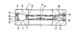
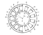
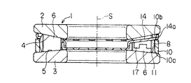
図1および図2には第1実施形態を示してあり、この実施形態における軸受1は上下に配置して互いに重なり合う一対の環状軌道輪2,3を備え、これら環状軌道輪2,3の互いに対向する環状の面が軌道面4,5で、これら軌道面4,5の対向間に複数の円錐ころ6が均等的にかつ放射状に配設されている。
【0042】
これら円錐ころ6は周面が円錐形状をなし、この円錐形状の周面が前記軌道面4,5に接する転動面7となっている。また、これら円錐ころ6の大径側の端面は外側に凸となる球面状の球面部8となっている。
【0043】
これら円錐ころ6の外周側周囲には浮動軌道輪10が設けられ、この浮動軌道輪10の内周面が円錐ころ6を取り囲んでその円錐ころ6の球面部8と接する軌道面11となっており、この軌道面11の軸方向沿いの形状が、図3に示すように円弧状に凹む凹曲形状となっている。
【0044】
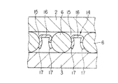
また、環状軌道輪2,3の軌道面4,5間には保持器14が設けられ、この保持器14は環形のほぼ円盤状をなし、その板面には各円錐ころ6を取り囲んでその転がり方向の姿勢を保つためのポケット部15が打ち抜き加工により形成され、これらポケット部15の相互間が柱部16となっている。
【0045】
各柱部16の両側の側縁には、図4に示すように、ポケット部15の打ち抜き部分の余肉を利用して、軸受1の軸方向に向かって伸びる羽根状の支持部17が形成され、その互いに対向する支持部17により円錐ころ6が抱きかかえられるように支持されている。
【0046】
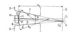
図3に示すように、環状軌道輪2,3における一方の軌道面4の傾斜の延長線と他方の軌道面5の傾斜の延長線との交点はC1で、また図2に示すように円錐ころ6の転動面7を形成する円錐の頂点はC2であり、これら交点C1および頂点C2は軸受1の中心軸S上で、かつ円錐ころ6の球面部8の中心Oを通る軸受1の中心軸Sと直角の水平な平面より離れたその下方側のA点において一致している。
【0047】
また、円錐ころ6の球面部8の曲率半径はR1、浮動軌道輪10における軌道面11の周方向沿いの円弧の最大半径はR2、浮動軌道輪10における軌道面11の軸方向沿いの凹曲の曲率半径はR3であり、球面部8の曲率半径R1は、浮動軌道輪10における軌道面11の周方向沿いの円弧の最大半径R2、および浮動軌道輪10における軌道面11の軸方向沿いの凹曲の曲率半径R3より小さくなっている。
【0048】
このような構成においては、環状軌道輪2,3における軌道面4,5の傾斜延長線の交点C1、および円錐ころ6における転動面7の円錐頂点C2が軸受1の中心軸S上のA点で一致しているから、円錐ころ6の転動面7が環状軌道輪2,3の軌道面4,5の上で完全な転がり運動をし、転がりに伴うスピンや差動すべりが存在しない。
【0049】
また、図5に示すように、軸受1に軸方向の荷重Wが加わったときには、軌道面4,5が傾斜しているため、円錐ころ6を軸受1の中心軸Sから遠ざける方向に押圧して浮動軌道輪10を押し広げようとする分力W′が生じ、この分力W′で円錐ころ6が最大のピッチ半径の位置に広がり、円錐ころ6の球面部8が図3に示すように浮動軌道輪10の軌道面11の最大径の点Pで接触する。
【0050】
そして、交点C1および頂点C2が軸受1の中心軸S上で、かつ円錐ころ6の球面部8の中心Oを通る水平な平面より下方のA点で一致している関係で、一方の環状軌道輪2の軌道面4と他方の環状軌道輪3の軌道面5との水平面に対する傾斜の角度が異なっており、これにより接触点Pは円錐ころ6の球面部8の中心Oから外れた位置になるが、球面部8の中心Oと接触点Pとの距離が近いため、接触点Pでの球面部8は、軸受1の回転に伴い、円錐ころ6の転動面7の転がり速度よりも遥かに遅い速度の転がりを伴うスピン運動をすることになり、この接触部分の面に潤滑剤が供給されるので、潤滑不良によるかじりや焼付きを生ずることがなく、小さな摩擦トルクで動くピボットを形成することは従来の低摩擦トルクスラスト玉軸受と同じとなる。
【0051】
したがって、この構成の軸受1では、従来の低摩擦トルクスラスト玉軸受から軌道面における差動すべりが除かれたことになり、低摩擦トルクのスラスト軸受を実現できる。
【0052】
このようにこの発明の軸受1では、浮動軌道輪10の軌道面11に接触する対象が、玉よりも大きな曲率半径R1をもった円錐ころ6の球面部8であり、軌道面11との接触面における接触面圧を玉の場合よりも低くできるので、軌道面11の軸方向断面の曲率半径R3を大きくしても、球面部8との接触面における面圧は過大にはならない。
【0053】
浮動軌道輪10の軌道面11の軸方向断面の曲率半径R3を大きくすると、浮動軌道輪10の位置と姿勢の安定性は損なわれるが、曲率半径R3が大きいことは、位置や姿勢が変化しても接触位置の変化が鈍感になる効果をもたらすので、接触面にかじりの核になるような純スピン運動になる点が生じにくくなる。したがって、従来の低摩擦トルクスラスト玉軸受よりもかじりや焼付きに対する安全余裕度が高くなる。
【0054】
通常の円錐ころ軸受では、円錐ころの大径側端面の球面部が環状軌道輪に形成された鍔の内面と線接触または面接触するので、この接触面で円錐ころの転動方向の姿勢が安定して保たれる。
【0055】
しかし、この発明の軸受1では、浮動軌道輪10の軌道面11と円錐ころ6の球面部8とは点接触であるために、その接触点Pで円錐ころ6の姿勢を保持するような作用はなく、円錐ころ6は転動面7が保持器14のポケット部15の内周で保持されてその回転が案内されることによって安定した姿勢が保たれる。
【0056】
各円錐ころ6は、保持器14におけるポケット部15の打ち抜き部分の余肉を利用して形成された支持部17により抱きかかえられるように支持されて保持器14と一体化されており、このため各円錐ころ6と保持器14とを一体の部品として扱え、軸受1を機械や装置に組み付ける際の作業を容易に能率よく行なうことができる。
【0057】
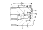
図6には第2の実施形態を示してあり、この実施形態においては、浮動軌道輪10の軌道面11が軸受1の中心軸Sと平行な円筒面となっている。
【0058】
円錐ころ6の球面部8の曲率半径は玉軸受における玉の半径に比べて大きく、浮動軌道輪10の軌道面11の軸方向断面の曲率半径を玉軸受の場合より大きくしても、球面部8と軌道面11との接触面での面圧は過大にならず、したがって軌道面11の曲率半径を無限大、すなわち軸受1の中心軸Sと平行な円筒面とすることが可能である。
【0059】
この構成の場合には、円錐ころ6が軸受1の外側に押し出される分力で浮動軌道輪10の位置と姿勢を安定にする作用は生じない。浮動軌道輪10が一旦傾けば、分力は浮動軌道輪10をさらに傾ける方向に働く。
【0060】
そこで、この実施形態においては、環状軌道輪3の軌道面5および保持器14の外周部14aと、浮動軌道輪10の端面10a,10bとの間の隙間を小さくして浮動軌道輪10を支持するようにしてある。これにより浮動軌道輪10の軸方向への移動を制限し、また浮動軌道輪10の傾きを抑え、円錐ころ6の球面部8と軌道面11との接触する位置の変化を小さくして、かじりや焼付きを防ぐことができる。
【0061】
図7には第3の実施形態を示してあり、この実施形態においては、浮動軌道輪10の軌道面11を軸受1の中心軸Sに対して小さな角度θでテーパ状に傾く円錐面となっている。
【0062】
この構成の場合には、図8に示すように、軸受1に軸方向の荷重Wが加わり、円錐ころ6を軸受1の中心軸Sから遠ざける方向に押圧する力が生じたときに、軌道面11が傾斜していることから浮動軌道輪10を環状軌道輪3の軌道面5に押し付ける小さな分力W′が生じ、この分力W′で浮動軌道輪10の位置と姿勢を安定して保持することができる。
【0063】
図9(A)には第4の実施形態を示してあり、この実施形態においては、環状軌道輪3の軌道面5が軸受1の中心軸Sと直角な水平な平面に形成されている。
【0064】
この構成においては、環状軌道輪3の軌道面5が水平な平面であるため、他方の環状軌道輪2、円錐ころ6、浮動軌道輪10および保持器14は軌道面5の上を半径方向に自由に動くことができ、この軸受1では半径方向の荷重を全く支持しない。半径方向の位置および荷重の支持は別に設けた半径方向軸受に依存する。
【0065】
この実施形態の軸受1は、ハーフ・トロイダル型無段変速機の伝動ローラに適用した場合であり、図9(B)に例示する従来の玉軸受1′に比べてその構成が簡略化し、その軸方向の長さが短くなり、これにより生じる空間の余裕を、伝動ローラを支持するトラニオンの剛性の向上や軽量化に活用することができ、さらに、従来の玉軸受の場合のように、伝動ローラの荷重が加わる方向に、その剛性を低下させる軌道面溝が存在しないので、伝動ローラの剛性が高く、トルク伝達に際して伝動ローラの変形が小さいので、これも変速機の伝達効率を向上させる上で有利となる。
【0066】
図10には第5の実施形態を示してあり、図10(A)は軸受1の一部の断面図、図10(B)は図10(A)中のX―X線に沿う断面図である。この実施形態においては、保持器14の外周部14aおよび内周部14bに、環状軌道輪2の軌道面4に対向して保持器14の軸方向の移動を規制する規制部20が設けられている。
【0067】
通常の円錐ころ軸受では、保持器は円錐形状をなし、円錐ころにより支持されているので、その半径方向および軸方向への位置の自由度が小さく、保持器が外輪と接触することはないのが普通である。
【0068】
しかし、この発明の軸受1では保持器14がほぼ平盤状をなし、その軸方向位置を円錐ころ6によって保持することが困難なので、保持器14が一方の環状軌道輪2に接触し、柱部16が円錐ころ6と軌道面4との間に挟まれ、潤滑が特に不良な場合には円錐ころ6が柱部16に乗り上げ、軸受1の回転を不能にする場合が起こり得る。
【0069】
ところが、この実施形態においては、保持器14の規制部20が、環状軌道輪2の軌道面4に接触することにより、保持器14の軸方向への動きが制限され、したがって保持器14のポケット部15と円錐ころ6の転動面7との接触位置21を、軌道面4とは距離をおいた、円錐ころ6の直径に近い位置に保つことができ、このため保持器14の柱部16が環状軌道輪2の軌道面4に接触したり、柱部16が円錐ころ6の転動面7と環状軌道輪2の軌道面4との間に挟まれるようなことがなく、潤滑が特に不良な場合であっても軸受1の回転を不能にするような恐れを防止することができる。
【0070】
また、この構成においては、保持器14が円錐ころ6の中心から遠ざかる位置に配置しており、このため円錐ころ6の中間部に配置する場合に比べてポケット部15の幅を小さく、すなわち柱部16の根元部分の幅を広くすることができ、これにより柱部16、特にその根元部分の強度が高くなり、保持器14の剛性が増し、これによって生じる余裕を円錐ころ6の数を増やすことに振り向けて、軸受1の耐久性の向上を図ることが可能となる。
【0071】
図11には第6の実施形態を示してあり、図10(A)は軸受1の一部の断面図、図10(B)は図10(A)中のX―X線に沿う断面図である。この実施形態においては、保持器14の柱部16の側縁に環状軌道輪2の軌道面4に向かって張り出す規制部22が設けられている。
また、保持器14の内周部14bには、円錐ころ6の相互間内に延びて柱部16と対向する支持部23が一体に形成されている。柱部16は円錐ころ6の中心より上方に、支持部23は円錐ころ6の中心より下方に配置し、各円錐ころ6は互いに隣り合った柱部16および支持部23とで抱き込まれて保持器14に保持されている。
【0072】
この構成においては、規制部22が環状軌道輪2の軌道面4に接触して保持器14の軸方向への動きが制限され、したがって前記第5の実施形態と同様に、保持器14のポケット部15と円錐ころ6の転動面7との接触位置21を、軌道面4とは距離をおいた、円錐ころ6の直径に近い位置に保つことができ、このため保持器14の柱部16が環状軌道輪2の軌道面4に接触したり、柱部16が円錐ころ6の転動面7と環状軌道輪2の軌道面4との間に挟まれるようなことがなく、潤滑が特に不良な場合であっても軸受1の回転を不能にするような恐れを防止することができる。
【0073】
また、この構成においては、保持器14が円錐ころ6の中心から遠ざかる位置に配置しており、このため円錐ころ6の中間部に配置する場合に比べてポケット部15の幅を小さく、すなわち柱部16の根元部分の幅を広くすることができ、これにより柱部16の根元部分の強度が高くなり、保持器14の剛性が増す。
【0074】
特にこの第6の実施形態においては、柱部16の側縁に軌道面4に向って張り出す規制部22が一体に形成されているから、保持器14の剛性がさらに増す。そして、これによって生じる余裕を円錐ころ6の数を増やすことに振り向けて、軸受1の耐久性の向上を図ることが可能となる。
【0075】
また、この第6の実施形態においては、各円錐ころ6が互いに隣り合った柱部16および支持部23とで抱き込まれて保持器14に一体的に結合されているから、保持器14および円錐ころ6を一体の部品として扱うことができ、したがって軸受1を機械や装置に組み付ける際の作業を容易に能率よく行なうことができる。
【0076】
図12には第7の実施形態を示してあり、この実施形態においては、保持器14の柱部16の両側の側縁に軸受1の軸方向に向かって伸びる羽根状の支持部17が形成され、その互いに対向する支持部17により円錐ころ6が抱きかかえられるように支持されて保持器14と各円錐ころ6とが一体化されている。
【0077】
また保持器14の外周部14aには、浮動軌道輪10の外周面との間に隙間をあけて対向する円筒部25が一体に形成され、この円筒部25で浮動軌道輪10の外周が囲まれている。そして円筒部25の下端縁が内側に僅かに屈曲する屈曲部25aとなっており、これにより円筒部25の下端の開口の内径寸法D1が浮動軌道輪10の外径寸法D2より小さくなっている。
【0078】
この構成においては、浮動軌道輪10が保持器14の円筒部25内に保持されてその抜け出しが防止され、保持器14、円錐ころ6および浮動軌道輪10の三者を一体の部品として扱うことができ、軸受1を機械や装置に組み付ける際の作業を容易に能率よく行なうことができる。
【0079】
図13には第8の実施形態を示してあり、この実施形態においては、保持器14が上下に重ね合わされた二枚の円環状部材26,27で構成されている。これら二枚の円環状部材26,27には円錐ころ6の周囲を取り囲むポケット部の相互間の柱部16の両側の側縁に支持部17が形成され、これら支持部17により円錐ころ6が抱きかかえられるように支持されてその脱落が防止されている。そして円錐ころ6の外周側に配置された浮動軌道輪10が、重ね合わされた二枚の円環状部材26,27の外周部の内側の空間29内に収容されている。
【0080】
この構成においては、二枚の円環状部材26,27で構成された保持器14と、円錐ころ6と、浮動軌道輪10とが一体的に結合され、したがって第6の実施形態の場合と同様に保持器14、円錐ころ6、浮動軌道輪10とを一体の部品として扱うことができ、軸受1を機械や装置に組み付ける際の作業を容易に能率よく行なうことができる。
【0081】
図14には第9の実施形態を示してあり、この実施形態においては、保持器14の内周部14bに、環状軌道輪3の内周面との間に隙間をあけて対向する円筒部30が一体に形成されている。環状軌道輪3の内周面の下部には段差部31が形成され、前記円筒部30の下端縁が前記段差部31内に入り込むように外側に僅かに屈曲し、この屈曲により円筒部30の下端の開口の外径寸法D1が段差部の上部側における環状軌道輪3の内径寸法D2より大きくなっており、これにより環状軌道輪3と保持器14とが離脱不能に結合されている。
【0082】
また、保持器14の柱部16の両側の側縁にはその上方側に張り出す支持部17が形成され、これら支持部17と環状軌道輪3の軌道面5とで円錐ころ6が挟み込まれるように支持されてその離脱が防止され、さらに浮動軌道輪10が保持器14の外周部14aと環状軌道輪3の軌道面5との間に配置してその離脱が防止されている。
【0083】
この構成においては、環状軌道輪3、保持器14、円錐ころ6、浮動軌道輪10が一体的に結合し、したがってこれら環状軌道輪3、保持器14、円錐ころ6、浮動軌道輪10を一体の部品として取り扱うことができ、軸受1を機械や装置に組み付ける際の作業を容易に能率よく行なうことができる。
【0084】
図15には第10の実施形態を示してあり、この実施形態においては、保持器14の外周部14aに、環状軌道輪2の外周面との間に隙間をあけて対向する円筒部32が一体に形成されている。環状軌道輪2の外周面の上部には段差部33が形成され、前記円筒部32の上端縁が前記段差部33内に入り込むように内側に僅かに屈曲し、この屈曲により円筒部32の上端の開口の内径寸法D1が段差部33の下部側における環状軌道輪2の外径寸法D2より小さくなっており、これにより環状軌道輪2と保持器14とが離脱不能に結合されている。
【0085】
また、保持器14の柱部16の両側の側縁にはその下方側に張り出す支持部17が形成され、これら支持部17により円錐ころ6が保持器に対して離脱不能に支持されている。
【0086】
この構成においては、環状軌道輪2、保持器14、円錐ころ6が一体的に結合され、したがってこれら環状軌道輪2、保持器14、円錐ころ6を一体の部品として取り扱うことができ、軸受1を機械や装置に組み付ける際の作業を容易に能率よく行なうことができる。
【0087】
【発明の効果】
以上説明したようにこの発明よれば、一対の環状軌道輪の軌道面と円錐ころの転動面との間で、玉軸受においては避け得ない差動すべりやスピンに基づくすべり運動が除かれて、極めて小さな摩擦を示す完全な転がり運動をし、また、円錐ころの大径側端面の球面部と浮動軌道輪の軌道面との接触面では、環状軌道輪の軌道面におけるよりも遥かに遅い転がり運動を伴うピボット運動となり、この接触面での摩擦は極めて小さいので、摩擦トルクの著しく小さい軸受を提供することができる。
【0088】
また、円錐ころの大径側端面の球面部と浮動軌道輪の軌道面との間の接触面では、ピボット運動に遅いながらも転がり運動を伴っているために潤滑剤が供給され、かつ、浮動軌道輪の位置や姿勢の変化に対して、円錐ころの球面部の浮動軌道輪の軌道面と接触する位置が変化しにくいため、円錐ころの球面部と浮動軌道輪の軌道面との間にかじりや焼付きを生ずる恐れが除かれる。
【0089】
さらに、一方の環状軌道輪の軌道面を平面とすることにより、ハーフ・トロイダル型無段変速機の伝動ローラに適用した場合には、その周辺構造を簡略化して、それにより生まれたスペースの余裕を変速機の性能の向上や軽量化に活用することができる。
【0090】
そして、保持器と円錐ころとを互いに離脱不能に結合したり、保持器と円錐ころと浮動軌道輪とを互いに離脱不能に結合したり、保持器と円錐ころと浮動軌道輪と一対の環状軌道輪のうちのいずれか一方とを互いに離脱不能に結合したり、保持器と円錐ころと一対の環状軌道輪のうちのいずれか一方とを互いに離脱不能に結合する構成を採用することが可能で、これにより軸受を機械や装置に組み付ける際の作業を容易に能率よく行なうことができる。
【図面の簡単な説明】
【図1】この発明の第1の実施形態に係るスラスト円錐ころ軸受を示す断面図。
【図2】その軸受の上部側の環状軌道輪を取り除き、かつ保持器の一部を破断した状態の平面図。
【図3】その軸受の要部の構成を示す説明図。
【図4】その軸受の円錐ころの配置部分の断面図。
【図5】その軸受の作用を説明するための説明図。
【図6】この発明の第2の実施形態に係るスラスト円錐ころ軸受を示す断面図。
【図7】この発明の第3の実施形態に係るスラスト円錐ころ軸受を示す断面図。
【図8】その軸受の作用を説明するための説明図。
【図9】この発明の第4の実施形態に係るスラスト円錐ころ軸受を従来の軸受と比較して示す断面図。
【図10】この発明の第5の実施形態に係るスラスト円錐ころ軸受を示し、(A)は軸受の一部の断面図、(B)は(A)の図におけるX―X線に沿う断面図。
【図11】この発明の第6の実施形態に係るスラスト円錐ころ軸受を示し、(A)は軸受の一部の断面図、(B)は(A)の図におけるX―X線に沿う断面図。
【図12】この発明の第7の実施形態に係るスラスト円錐ころ軸受の一部を示す断面図。
【図13】この発明の第8の実施形態に係るスラスト円錐ころ軸受の一部を示す断面図。
【図14】この発明の第9の実施形態に係るスラスト円錐ころ軸受の一部を示す断面図。
【図15】この発明の第10の実施形態に係るスラスト円錐ころ軸受の一部を示す断面図。
【符号の説明】
1…軸受
2,3…環状軌道輪
4,5…軌道面
6…円錐ころ
7…転動面
8…球面部
10…浮動軌道輪
11…軌道面
14…保持器
15…ポケット部
16…柱部
17支持部[0001]
BACKGROUND OF THE INVENTION
The present invention relates to a low friction torque thrust tapered roller bearing, and particularly, a large axial load such as a transmission roller and input / output member of a half-toroidal type traction drive continuously variable transmission, a machine tool, a resin injection molding machine or the like. The present invention relates to a thrust tapered roller bearing having a low friction torque suitable for supporting a member that rotates in response to a low friction.
[0002]
[Prior art]
In half-toroidal traction drive continuously variable transmissions, the transmission roller support bearings rotate at a high speed while receiving large axial and radial loads, so the transmission efficiency of the power transmission unit is higher than other methods. In order to further increase the transmission efficiency of this type of half-toroidal continuously variable transmission, it is an important factor to reduce the friction loss of the support bearing.
[0003]
In this type of continuously variable transmission, the input and output disks rotate at high speeds in opposite directions while receiving a large axial load. Therefore, in order to avoid friction loss of the bearings supporting these disks, There are many examples of dual cavity systems in which the input and output disks are coaxially arranged back to back.
[0004]
However, in the dual cavity method, since two sets of input and output disks are coaxially arranged in the length direction, the transmission has a shape that is long in the axial direction, and when this is applied to an automobile, Although it can be applied to a rear wheel drive vehicle having a space in the length direction, it is difficult to apply to a front wheel drive vehicle in which the length of the transmission must be made as short as possible.
[0005]
In other words, in order to be applied to a front-wheel drive vehicle, it is necessary to adopt a single cavity system that uses only one set of input and output disks. For this purpose, the friction loss of the bearing that supports the input and output disks is reduced. Is an indispensable condition.
[0006]
As described above, in the half-toroidal continuously variable transmission, the friction loss of the transmission roller and the support bearing of the input / output member determines the transmission efficiency of the transmission, and consequently the success or failure of the continuously variable transmission. Reduction of friction torque is strongly demanded.
[0007]
There are thrust ball bearings and angular contact ball bearings as bearings for applications that require high friction while rotating at a high speed while receiving a large axial load. However, in this type of bearing, the spin friction at the contact point between the ball and the raceway surface is large, and the friction torque is much larger than when a normal radial bearing rotates under a radial load.
[0008]
In order to improve the disadvantages of such thrust ball bearings and angular contact ball bearings, a floating bearing ring having a raceway surface having a concave arc-shaped cross section is provided on the outer peripheral side of the ball, so that the ball is supported more than the normal position. A low-friction torque thrust ball bearing that is biased toward the central axis so that the ball makes a pure rolling motion on the raceway surface, except for the spin at the contact point between the ball and the raceway surface of the two annular races. U.S. Pat. No. 1,423,666 has been proposed.
[0009]
In this bearing, the spin at the contact point between the ball and the raceway surface of the two annular races is almost eliminated, and the contact point between the raceway surface of the floating race and the ball is a point contact that forms a small ellipse. Since the movement during this time is a pivoting movement, the friction loss is remarkably small, and as a result, the friction torque of the bearing is reduced. Then, a difference is made in the contact angle between the ball and the two raceways, the center of the contact point is set to a position different from the center of rotation of the ball, and the ring raceway is placed between the raceway surface of the floating raceway and the ball. The rolling motion at a speed much slower than the rolling speed between the raceway surface and the ball is added to prevent poor lubrication at the contact point due to the pivoting motion, and to prevent the contact surface from galling and seizure.
[0010]
In addition, a tapered roller bearing can be used if it is used only for receiving a large axial load and rotating. However, this bearing has a large friction torque and is not suitable for high-speed rotation.
[0011]
[Problems to be solved by the invention]
In the conventional low friction torque thrust ball bearing described above, the spin at the contact point between the ball and the raceway surface of the two annular races can be almost eliminated, and the contact point between the raceway surface of the floating raceway and the ball. Since the rolling motion is performed even a little at a time, the lubricant is supplied to this contact point, and the load at this contact point is smaller than the load between the raceway surface of the annular race and the ball, and the rolling speed is slow. Therefore, the friction loss at this contact point is smaller than the friction loss of the entire bearing, the friction torque of the bearing is reduced to about 2/3 to 1/2 of that of a normal thrust ball bearing, and Scratching and seizure at the contact point between the raceway surface and the ball are almost prevented.
[0012]
However, there are still significant factors of friction in this low friction torque thrust ball bearing. The friction factors of this bearing, except for those related to the agitation of the lubricant, are due to the spin and gentle rolling at the contact point between the raceway surface of the floating race and the ball, and the contact point between the raceway surface and the ball. Due to elastic hysteresis, and due to differential slip when the ball rolls on the raceway surface of the annular race.
[0013]
Of these, the first two are not large, but in ball bearings, the contact ellipse at the contact point between the raceway surface and the ball is curved in a direction perpendicular to the ball rolling direction, and the contact ellipse increases with increasing load. As the diameter increases, the friction due to differential sliding increases as well as the friction due to spin in a normal thrust ball bearing.
[0014]
Therefore, when a conventional low friction torque thrust bearing is used with a large load, the friction due to differential slip is a major obstacle to reducing the friction torque. If this differential slip can be removed, the friction torque of the bearing will be further increased. Will be reduced.
[0015]
The differential slip is an unavoidable slip in a ball bearing that is generated when the raceway surface of the annular race and the rolling surface of the rolling element are curved surfaces that are curved in a direction perpendicular to the rolling direction. Therefore, if it is not a ball bearing but a roller bearing whose raceway surface and rolling surface are straight, and if conventional friction reduction technology can be applied to this roller bearing, there will be no friction due to spin or friction loss due to differential sliding, It is possible to obtain a thrust bearing having a lower friction torque than that of the prior art.
[0016]
In this sense, a tapered roller bearing that has a complete rolling motion without friction loss due to spin or differential slip on the raceway surface is an ideal bearing. Further, since the contact on the raceway surface is a line contact, the load capacity is higher than that of the ball bearing. However, the tapered roller bearing has a drawback in that sliding friction loss occurs between the spherical portion of the large-diameter end surface of the tapered roller and the flange surface of the inner ring (annular race ring). That is, if the friction loss on the flange surface can be removed from the tapered roller bearing, a thrust bearing having a low friction torque and a long life can be realized.
[0017]
The present invention has been made under such a background, and an object of the present invention is to provide a thrust tapered roller bearing having a remarkably small frictional torque.
[0018]
[Means for Solving the Problems]
According to the first aspect of the present invention, a pair of annular races which are arranged to face each other and each have an annular raceway surface on the opposite surface side, and are rotatably interposed between the raceway surfaces of these annular raceways. A plurality of tapered rollers, a floating race that surrounds the outer periphery of these tapered rollers, and a cage that holds each tapered roller, and each tapered roller has a circumferential surface that is in contact with the raceway surface of each annular race. On the rolling surface, the end surface on the large diameter side is a spherical surface convex outwardly, and the inner peripheral surface of the floating race is the raceway surface in contact with the spherical portion of the tapered roller. Is a conical surface inclined with respect to its axial direction The raceway surface of one annular raceway and the raceway surface of the other annular raceway that are opposed to each other are inclined in a tapered manner on the opposite sides, and an extension line of the slope of one raceway surface and the other raceway The axis of the bearing in which the intersection C1 with the extended line of the inclined surface of the surface and the conical apex C2 of the conical roller forming the peripheral surface of the tapered roller pass on the center axis of the bearing and through the center of the spherical portion of the tapered roller. It is characterized by being coincident at one point away from a plane perpendicular to the direction.
[0033]
If the raceway surface of the floating raceway is a conical surface inclined with respect to its axial direction, this component force is generated when a component force is generated to push the tapered roller to the outside of the bearing due to the axial load applied to the bearing. Thus, a force that presses the floating bearing ring against the raceway surface of the annular bearing ring acts, and this force can stabilize the position and posture of the floating bearing ring.
[0034]
[0035]
This
[0036]
In particular, when used as a support bearing for a transmission roller of a half-toroidal continuously variable transmission, a radial bearing for supporting a radial load, which is a reaction force of the transmission torque, is used together, and the position of the transmission roller is It is necessary to be able to move in the radial direction perpendicular to the direction of the radial load by torque transmission. Conventionally, the degree of freedom in the radial position of the transmission roller is supported by supporting the flat portion of the annular race ring opposite to the transmission roller on the side opposite to the raceway surface with a slide bearing or a thrust needle roller bearing. The complex means to give is taken.
[0037]
[0038]
Furthermore, in the case of a ball bearing, there is a groove on the raceway surface in the vicinity of the direction in which the load is applied to the transmission roller, which reduces the rigidity of the transmission roller. 2 In the bearing of this invention, there is no raceway groove in the load direction, so the deformation of the transmission roller is small during torque transmission, which is also advantageous for improving the transmission efficiency of the transmission.
[0039]
[0040]
DETAILED DESCRIPTION OF THE INVENTION
Hereinafter, specific embodiments of the present invention will be described with reference to the drawings.
[0041]
1 and 2 show a first embodiment. A bearing 1 in this embodiment includes a pair of annular race rings 2 and 3 that are arranged one above the other and overlap each other. Opposing annular surfaces are
[0042]
These
[0043]
A floating
[0044]
A
[0045]
As shown in FIG. 4, blade-
[0046]
As shown in FIG. 3, the intersection of the inclined extension line of one
[0047]
Further, the radius of curvature of the
[0048]
In such a configuration, the intersection C1 of the inclined extended lines of the raceway surfaces 4 and 5 in the
[0049]
Further, as shown in FIG. 5, when the axial load W is applied to the bearing 1, the raceway surfaces 4 and 5 are inclined, so that the tapered
[0050]
One of the annular raceways has a relationship in which the intersection C1 and the vertex C2 coincide with each other at a point A below the horizontal plane passing through the center O of the
[0051]
Therefore, in the bearing 1 having this configuration, the differential slip on the raceway surface is removed from the conventional low friction torque thrust ball bearing, and a low friction torque thrust bearing can be realized.
[0052]
Thus, in the bearing 1 of the present invention, the object that contacts the
[0053]
If the radius of curvature R3 of the axial section of the
[0054]
In ordinary tapered roller bearings, the spherical portion of the end surface on the large diameter side of the tapered roller is in line contact or surface contact with the inner surface of the flange formed on the ring raceway. It is kept stable.
[0055]
However, in the bearing 1 of the present invention, since the
[0056]
Each
[0057]
FIG. 6 shows a second embodiment. In this embodiment, the
[0058]
The radius of curvature of the
[0059]
In the case of this configuration, there is no effect of stabilizing the position and posture of the floating
[0060]
Therefore, in this embodiment, the clearance between the
[0061]
FIG. 7 shows a third embodiment. In this embodiment, the
[0062]
In the case of this configuration, as shown in FIG. 8, when an axial load W is applied to the bearing 1 and a force that pushes the tapered
[0063]
FIG. 9A shows a fourth embodiment. In this embodiment, the
[0064]
In this configuration, since the
[0065]
The bearing 1 of this embodiment is a case where it is applied to a transmission roller of a half-toroidal type continuously variable transmission, and its configuration is simplified compared to the conventional ball bearing 1 'illustrated in FIG. The axial length is shortened, and the resulting space allowance can be used to improve the rigidity and weight of the trunnion that supports the transmission roller. In addition, as in the case of conventional ball bearings, transmission Since there is no raceway groove that reduces the rigidity of the roller in the direction in which the roller is applied, the rigidity of the transmission roller is high and the deformation of the transmission roller is small during torque transmission. This also improves the transmission efficiency of the transmission. Is advantageous.
[0066]
FIG. 10 shows a fifth embodiment. FIG. 10A is a partial cross-sectional view of the bearing 1, and FIG. 10B is a cross-sectional view taken along line XX in FIG. It is. In this embodiment, the outer peripheral portion 14a and the inner peripheral portion of the
[0067]
In a normal tapered roller bearing, the cage has a conical shape and is supported by the tapered roller. Therefore, the radial and axial position of the cage is small, and the cage does not come into contact with the outer ring. Is normal.
[0068]
However, in the bearing 1 of the present invention, the
[0069]
However, in this embodiment, when the restricting
[0070]
Further, in this configuration, the
[0071]
FIG. 11 shows a sixth embodiment. FIG. 10A is a partial cross-sectional view of the bearing 1, and FIG. 10B is a cross-sectional view taken along line XX in FIG. It is. In this embodiment, a restricting
Further, a
[0072]
In this configuration, the restricting
[0073]
Further, in this configuration, the
[0074]
In particular, in the sixth embodiment, since the restricting
[0075]
Further, in the sixth embodiment, each
[0076]
FIG. 12 shows a seventh embodiment. In this embodiment, a blade-
[0077]
A
[0078]
In this configuration, the floating
[0079]
FIG. 13 shows an eighth embodiment. In this embodiment, the
[0080]
In this configuration, the
[0081]
FIG. 14 shows a ninth embodiment. In this embodiment, a cylindrical portion facing the inner
[0082]
Further,
[0083]
In this configuration, the
[0084]
FIG. 15 shows a tenth embodiment. In this embodiment, a
[0085]
Further,
[0086]
In this configuration, the
[0087]
【The invention's effect】
As described above, according to the present invention, the differential sliding and the sliding motion based on the spin that are unavoidable in the ball bearing are eliminated between the raceway surface of the pair of annular races and the rolling surface of the tapered roller. It has a complete rolling motion with very little friction, and the contact surface between the spherical surface of the large-diameter end surface of the tapered roller and the raceway surface of the floating raceway is much slower than the raceway surface of the ring raceway The pivoting motion is accompanied by a rolling motion, and the friction at this contact surface is extremely small, so that a bearing with a remarkably small friction torque can be provided.
[0088]
In addition, the contact surface between the spherical portion of the end surface on the large diameter side of the tapered roller and the raceway surface of the floating raceway is supplied with lubricant because it is accompanied by rolling motion although being slow in pivot motion. The position of the tapered roller spherical surface in contact with the raceway surface of the floating raceway is unlikely to change with changes in the position and orientation of the raceway, so there is no change between the spherical surface of the tapered roller and the raceway surface of the floating raceway. The risk of galling and seizure is eliminated.
[0089]
Furthermore, by making the raceway surface of one annular raceway into a flat surface, when applied to the transmission roller of a half-toroidal type continuously variable transmission, the peripheral structure is simplified and the margin of space created by that is simplified. Can be used to improve transmission performance and reduce weight.
[0090]
Then, the cage and the tapered roller are connected to each other so as not to be separated from each other, the cage, the tapered roller and the floating bearing ring are coupled to each other so as not to be separated from each other, or the cage, the tapered roller and the floating bearing ring are paired with an annular track. It is possible to adopt a configuration in which any one of the rings is detachably coupled to each other, or the cage, the tapered roller, and any one of the pair of annular raceways are detachably coupled to each other. As a result, the work for assembling the bearing to the machine or device can be easily and efficiently performed.
[Brief description of the drawings]
FIG. 1 is a sectional view showing a thrust tapered roller bearing according to a first embodiment of the invention.
FIG. 2 is a plan view showing a state where an annular race on the upper side of the bearing is removed and a part of the cage is broken.
FIG. 3 is an explanatory view showing a configuration of a main part of the bearing.
FIG. 4 is a cross-sectional view of a portion where tapered rollers of the bearing are arranged.
FIG. 5 is an explanatory diagram for explaining the operation of the bearing.
FIG. 6 is a sectional view showing a thrust tapered roller bearing according to a second embodiment of the invention.
FIG. 7 is a sectional view showing a thrust tapered roller bearing according to a third embodiment of the invention.
FIG. 8 is an explanatory diagram for explaining the operation of the bearing.
FIG. 9 is a sectional view showing a thrust tapered roller bearing according to a fourth embodiment of the present invention in comparison with a conventional bearing.
10A and 10B show a thrust tapered roller bearing according to a fifth embodiment of the present invention, in which FIG. 10A is a sectional view of a part of the bearing, and FIG. 10B is a sectional view taken along line XX in FIG. Figure.
11A and 11B show a thrust tapered roller bearing according to a sixth embodiment of the present invention, in which FIG. 11A is a partial cross-sectional view of the bearing, and FIG. 11B is a cross-sectional view taken along line XX in FIG. Figure.
FIG. 12 is a sectional view showing a part of a thrust tapered roller bearing according to a seventh embodiment of the invention.
FIG. 13 is a sectional view showing a part of a thrust tapered roller bearing according to an eighth embodiment of the invention.
FIG. 14 is a sectional view showing a part of a thrust tapered roller bearing according to a ninth embodiment of the invention.
FIG. 15 is a sectional view showing a part of a thrust tapered roller bearing according to a tenth embodiment of the invention.
[Explanation of symbols]
1 ... Bearing
2, 3 ... Annular race
4, 5 ... orbital surface
6 ... Tapered rollers
7 ... Rolling surface
8 ... Spherical surface
10 ... Floating race
11 ... Race surface
14 ... Retainer
15 ... Pocket
16 ... pillar
17 support part
Claims (7)
各円錐ころは周面が各環状軌道輪の軌道面に接する転動面で、大径側の端面がその外側に凸の球面部となっており、浮動軌道輪の内周面は円錐ころの前記球面部が接する軌道面で、この軌道面がその軸方向に対して傾く円錐面となっており、
互いに対向した一方の環状軌道輪の軌道面と他方の環状軌道輪の軌道面は、互いに反対側にテーパ状に傾斜し、一方の軌道面の傾斜の延長線と他方の軌道面の傾斜の延長線との交点C1と、円錐ころの周面を形成する円錐形の円錐頂点C2とが、軸受の中心軸上で、かつ円錐ころの前記球面部の中心を通る軸受の軸方向と直角の平面より離れた位置の一点で一致していることを特徴とするスラスト円錐ころ軸受。A pair of annular races arranged opposite to each other and each having an annular raceway on the opposite surface side, and a plurality of tapered rollers interposed between the raceway surfaces of the annular raceways so as to be capable of rolling. A floating race ring surrounding the outer periphery of these tapered rollers, and a cage holding each tapered roller,
Each tapered roller is a rolling surface whose peripheral surface is in contact with the raceway surface of each annular raceway, and the end surface on the large diameter side is a convex spherical portion on the outside, and the inner circumferential surface of the floating raceway is the tapered roller The raceway surface is in contact with the spherical surface, the raceway surface is a conical surface inclined with respect to the axial direction,
The raceway surface of one annular raceway and the raceway surface of the other annular raceway that are opposed to each other are inclined in a tapered manner on opposite sides, and an extension line of the slope of one raceway surface and an extension of the slope of the other raceway surface are provided. A plane perpendicular to the axial direction of the bearing on the center axis of the bearing and the center of the spherical portion of the tapered roller is an intersection C1 with the line and a conical apex C2 forming a circumferential surface of the tapered roller. A thrust tapered roller bearing characterized by being coincident at one point at a more distant position.
Priority Applications (1)
| Application Number | Priority Date | Filing Date | Title |
|---|---|---|---|
| JP21519799A JP4239307B2 (en) | 1999-07-29 | 1999-07-29 | Thrust tapered roller bearing |
Applications Claiming Priority (1)
| Application Number | Priority Date | Filing Date | Title |
|---|---|---|---|
| JP21519799A JP4239307B2 (en) | 1999-07-29 | 1999-07-29 | Thrust tapered roller bearing |
Publications (3)
| Publication Number | Publication Date |
|---|---|
| JP2001041230A JP2001041230A (en) | 2001-02-13 |
| JP2001041230A5 JP2001041230A5 (en) | 2005-09-02 |
| JP4239307B2 true JP4239307B2 (en) | 2009-03-18 |
Family
ID=16668305
Family Applications (1)
| Application Number | Title | Priority Date | Filing Date |
|---|---|---|---|
| JP21519799A Expired - Fee Related JP4239307B2 (en) | 1999-07-29 | 1999-07-29 | Thrust tapered roller bearing |
Country Status (1)
| Country | Link |
|---|---|
| JP (1) | JP4239307B2 (en) |
Families Citing this family (10)
| Publication number | Priority date | Publication date | Assignee | Title |
|---|---|---|---|---|
| JP2003166610A (en) | 2001-12-03 | 2003-06-13 | Nissan Motor Co Ltd | Toroidal continuously variable transmission |
| DE102004039845B4 (en) * | 2004-08-18 | 2013-04-11 | Schaeffler Technologies AG & Co. KG | Tapered roller bearings |
| JP2006329219A (en) * | 2005-05-23 | 2006-12-07 | Jtekt Corp | Thrust roller bearing |
| JP5040552B2 (en) * | 2007-09-21 | 2012-10-03 | 株式会社ジェイテクト | Rolling bearing device |
| WO2017149829A1 (en) * | 2016-03-04 | 2017-09-08 | Gkn ドライブライン ジャパン株式会社 | Cam mechanism and clutch device using said cam mechanism |
| JP6735180B2 (en) * | 2016-03-04 | 2020-08-05 | ジーケーエヌ オートモーティブ リミテッド | A cam mechanism and a clutch device using this cam mechanism. |
| CN107830049B (en) * | 2017-12-05 | 2023-08-29 | 大连交通大学 | Low friction loss thrust tapered roller bearing |
| WO2019171459A1 (en) * | 2018-03-06 | 2019-09-12 | Gkn ドライブライン ジャパン株式会社 | Low-hysteresis cam mechanism provided with tapered rollers |
| JP6912666B2 (en) * | 2018-06-20 | 2021-08-04 | ジーケーエヌ オートモーティブ リミテッド | Low hysteresis cam mechanism with tapered rollers |
| CN113062963A (en) * | 2021-04-12 | 2021-07-02 | 王踊 | Large torque thrust hobbing gear and transmission using same |
-
1999
- 1999-07-29 JP JP21519799A patent/JP4239307B2/en not_active Expired - Fee Related
Also Published As
| Publication number | Publication date |
|---|---|
| JP2001041230A (en) | 2001-02-13 |
Similar Documents
| Publication | Publication Date | Title |
|---|---|---|
| US4565457A (en) | Radial, radial angular-contact, and axial angular-contact ball bearing | |
| JP3529191B2 (en) | Method of manufacturing spherical roller bearing with cage and cage for spherical roller bearing with cage | |
| JPS6182018A (en) | Radial roller bearing | |
| JP4239307B2 (en) | Thrust tapered roller bearing | |
| JP2994033B2 (en) | Improvement of roller bearing | |
| US5536091A (en) | Thrust ball bearing for use with power rollers | |
| JP3661371B2 (en) | Power roller bearing for toroidal type continuously variable transmission | |
| JP3638303B2 (en) | Thrust ball bearing for half toroidal type continuously variable transmission | |
| JP2008509345A (en) | Rotating homokinetic joint | |
| JP3303503B2 (en) | Thrust ball bearings for power rollers | |
| JP3637866B2 (en) | Toroidal continuously variable transmission | |
| JP4706920B2 (en) | Toroidal continuously variable transmission | |
| JP4710402B2 (en) | Toroidal continuously variable transmission | |
| JPH10141462A (en) | Troidal type continuously variable transmission | |
| JP4923989B2 (en) | Toroidal continuously variable transmission | |
| JP4068824B2 (en) | Constant velocity joint | |
| JP2014214838A (en) | Continuously variable transmission | |
| JPH0616753U (en) | Toroidal type continuously variable transmission | |
| JP3815054B2 (en) | Thrust ball bearing | |
| JPH07217660A (en) | Thrust ball bearing | |
| JPH10103348A (en) | Low friction torque thrust ball bearing | |
| US6896414B2 (en) | Ball roller | |
| JP2023012100A (en) | toroidal type continuously variable transmission | |
| JP3522522B2 (en) | Toroidal type continuously variable transmission | |
| JP3454156B2 (en) | Toroidal type continuously variable transmission |
Legal Events
| Date | Code | Title | Description |
|---|---|---|---|
| A521 | Written amendment |
Free format text: JAPANESE INTERMEDIATE CODE: A523 Effective date: 20050308 |
|
| A621 | Written request for application examination |
Free format text: JAPANESE INTERMEDIATE CODE: A621 Effective date: 20050308 |
|
| A977 | Report on retrieval |
Free format text: JAPANESE INTERMEDIATE CODE: A971007 Effective date: 20080319 |
|
| A131 | Notification of reasons for refusal |
Free format text: JAPANESE INTERMEDIATE CODE: A131 Effective date: 20080520 |
|
| A521 | Written amendment |
Free format text: JAPANESE INTERMEDIATE CODE: A523 Effective date: 20080716 |
|
| TRDD | Decision of grant or rejection written | ||
| A01 | Written decision to grant a patent or to grant a registration (utility model) |
Free format text: JAPANESE INTERMEDIATE CODE: A01 Effective date: 20081202 |
|
| A01 | Written decision to grant a patent or to grant a registration (utility model) |
Free format text: JAPANESE INTERMEDIATE CODE: A01 |
|
| A61 | First payment of annual fees (during grant procedure) |
Free format text: JAPANESE INTERMEDIATE CODE: A61 Effective date: 20081215 |
|
| FPAY | Renewal fee payment (event date is renewal date of database) |
Free format text: PAYMENT UNTIL: 20120109 Year of fee payment: 3 |
|
| R150 | Certificate of patent or registration of utility model |
Free format text: JAPANESE INTERMEDIATE CODE: R150 |
|
| FPAY | Renewal fee payment (event date is renewal date of database) |
Free format text: PAYMENT UNTIL: 20130109 Year of fee payment: 4 |
|
| FPAY | Renewal fee payment (event date is renewal date of database) |
Free format text: PAYMENT UNTIL: 20130109 Year of fee payment: 4 |
|
| FPAY | Renewal fee payment (event date is renewal date of database) |
Free format text: PAYMENT UNTIL: 20140109 Year of fee payment: 5 |
|
| LAPS | Cancellation because of no payment of annual fees |