JP4237256B2 - Ultrasonic transducer - Google Patents
Ultrasonic transducer Download PDFInfo
- Publication number
- JP4237256B2 JP4237256B2 JP53118597A JP53118597A JP4237256B2 JP 4237256 B2 JP4237256 B2 JP 4237256B2 JP 53118597 A JP53118597 A JP 53118597A JP 53118597 A JP53118597 A JP 53118597A JP 4237256 B2 JP4237256 B2 JP 4237256B2
- Authority
- JP
- Japan
- Prior art keywords
- transducer
- motion
- array
- tracking
- image data
- Prior art date
- Legal status (The legal status is an assumption and is not a legal conclusion. Google has not performed a legal analysis and makes no representation as to the accuracy of the status listed.)
- Expired - Fee Related
Links
Images


Classifications
-
- A—HUMAN NECESSITIES
- A61—MEDICAL OR VETERINARY SCIENCE; HYGIENE
- A61B—DIAGNOSIS; SURGERY; IDENTIFICATION
- A61B8/00—Diagnosis using ultrasonic, sonic or infrasonic waves
- A61B8/13—Tomography
- A61B8/14—Echo-tomography
- A61B8/145—Echo-tomography characterised by scanning multiple planes
-
- A—HUMAN NECESSITIES
- A61—MEDICAL OR VETERINARY SCIENCE; HYGIENE
- A61B—DIAGNOSIS; SURGERY; IDENTIFICATION
- A61B8/00—Diagnosis using ultrasonic, sonic or infrasonic waves
- A61B8/48—Diagnostic techniques
- A61B8/483—Diagnostic techniques involving the acquisition of a 3D volume of data
-
- G—PHYSICS
- G01—MEASURING; TESTING
- G01S—RADIO DIRECTION-FINDING; RADIO NAVIGATION; DETERMINING DISTANCE OR VELOCITY BY USE OF RADIO WAVES; LOCATING OR PRESENCE-DETECTING BY USE OF THE REFLECTION OR RERADIATION OF RADIO WAVES; ANALOGOUS ARRANGEMENTS USING OTHER WAVES
- G01S15/00—Systems using the reflection or reradiation of acoustic waves, e.g. sonar systems
- G01S15/88—Sonar systems specially adapted for specific applications
- G01S15/89—Sonar systems specially adapted for specific applications for mapping or imaging
- G01S15/8906—Short-range imaging systems; Acoustic microscope systems using pulse-echo techniques
- G01S15/8934—Short-range imaging systems; Acoustic microscope systems using pulse-echo techniques using a dynamic transducer configuration
-
- G—PHYSICS
- G01—MEASURING; TESTING
- G01S—RADIO DIRECTION-FINDING; RADIO NAVIGATION; DETERMINING DISTANCE OR VELOCITY BY USE OF RADIO WAVES; LOCATING OR PRESENCE-DETECTING BY USE OF THE REFLECTION OR RERADIATION OF RADIO WAVES; ANALOGOUS ARRANGEMENTS USING OTHER WAVES
- G01S15/00—Systems using the reflection or reradiation of acoustic waves, e.g. sonar systems
- G01S15/88—Sonar systems specially adapted for specific applications
- G01S15/89—Sonar systems specially adapted for specific applications for mapping or imaging
- G01S15/8906—Short-range imaging systems; Acoustic microscope systems using pulse-echo techniques
- G01S15/8979—Combined Doppler and pulse-echo imaging systems
-
- G—PHYSICS
- G01—MEASURING; TESTING
- G01S—RADIO DIRECTION-FINDING; RADIO NAVIGATION; DETERMINING DISTANCE OR VELOCITY BY USE OF RADIO WAVES; LOCATING OR PRESENCE-DETECTING BY USE OF THE REFLECTION OR RERADIATION OF RADIO WAVES; ANALOGOUS ARRANGEMENTS USING OTHER WAVES
- G01S15/00—Systems using the reflection or reradiation of acoustic waves, e.g. sonar systems
- G01S15/88—Sonar systems specially adapted for specific applications
- G01S15/89—Sonar systems specially adapted for specific applications for mapping or imaging
- G01S15/8906—Short-range imaging systems; Acoustic microscope systems using pulse-echo techniques
- G01S15/8993—Three dimensional imaging systems
-
- G—PHYSICS
- G01—MEASURING; TESTING
- G01S—RADIO DIRECTION-FINDING; RADIO NAVIGATION; DETERMINING DISTANCE OR VELOCITY BY USE OF RADIO WAVES; LOCATING OR PRESENCE-DETECTING BY USE OF THE REFLECTION OR RERADIATION OF RADIO WAVES; ANALOGOUS ARRANGEMENTS USING OTHER WAVES
- G01S7/00—Details of systems according to groups G01S13/00, G01S15/00, G01S17/00
- G01S7/52—Details of systems according to groups G01S13/00, G01S15/00, G01S17/00 of systems according to group G01S15/00
- G01S7/52017—Details of systems according to groups G01S13/00, G01S15/00, G01S17/00 of systems according to group G01S15/00 particularly adapted to short-range imaging
- G01S7/52085—Details related to the ultrasound signal acquisition, e.g. scan sequences
-
- G—PHYSICS
- G06—COMPUTING; CALCULATING OR COUNTING
- G06T—IMAGE DATA PROCESSING OR GENERATION, IN GENERAL
- G06T7/00—Image analysis
- G06T7/20—Analysis of motion
- G06T7/246—Analysis of motion using feature-based methods, e.g. the tracking of corners or segments
-
- G—PHYSICS
- G01—MEASURING; TESTING
- G01S—RADIO DIRECTION-FINDING; RADIO NAVIGATION; DETERMINING DISTANCE OR VELOCITY BY USE OF RADIO WAVES; LOCATING OR PRESENCE-DETECTING BY USE OF THE REFLECTION OR RERADIATION OF RADIO WAVES; ANALOGOUS ARRANGEMENTS USING OTHER WAVES
- G01S15/00—Systems using the reflection or reradiation of acoustic waves, e.g. sonar systems
- G01S15/66—Sonar tracking systems
-
- G—PHYSICS
- G01—MEASURING; TESTING
- G01S—RADIO DIRECTION-FINDING; RADIO NAVIGATION; DETERMINING DISTANCE OR VELOCITY BY USE OF RADIO WAVES; LOCATING OR PRESENCE-DETECTING BY USE OF THE REFLECTION OR RERADIATION OF RADIO WAVES; ANALOGOUS ARRANGEMENTS USING OTHER WAVES
- G01S15/00—Systems using the reflection or reradiation of acoustic waves, e.g. sonar systems
- G01S15/87—Combinations of sonar systems
-
- G—PHYSICS
- G01—MEASURING; TESTING
- G01S—RADIO DIRECTION-FINDING; RADIO NAVIGATION; DETERMINING DISTANCE OR VELOCITY BY USE OF RADIO WAVES; LOCATING OR PRESENCE-DETECTING BY USE OF THE REFLECTION OR RERADIATION OF RADIO WAVES; ANALOGOUS ARRANGEMENTS USING OTHER WAVES
- G01S7/00—Details of systems according to groups G01S13/00, G01S15/00, G01S17/00
- G01S7/52—Details of systems according to groups G01S13/00, G01S15/00, G01S17/00 of systems according to group G01S15/00
- G01S7/52017—Details of systems according to groups G01S13/00, G01S15/00, G01S17/00 of systems according to group G01S15/00 particularly adapted to short-range imaging
- G01S7/52023—Details of receivers
- G01S7/52034—Data rate converters
-
- G—PHYSICS
- G01—MEASURING; TESTING
- G01S—RADIO DIRECTION-FINDING; RADIO NAVIGATION; DETERMINING DISTANCE OR VELOCITY BY USE OF RADIO WAVES; LOCATING OR PRESENCE-DETECTING BY USE OF THE REFLECTION OR RERADIATION OF RADIO WAVES; ANALOGOUS ARRANGEMENTS USING OTHER WAVES
- G01S7/00—Details of systems according to groups G01S13/00, G01S15/00, G01S17/00
- G01S7/52—Details of systems according to groups G01S13/00, G01S15/00, G01S17/00 of systems according to group G01S15/00
- G01S7/52017—Details of systems according to groups G01S13/00, G01S15/00, G01S17/00 of systems according to group G01S15/00 particularly adapted to short-range imaging
- G01S7/52053—Display arrangements
- G01S7/52057—Cathode ray tube displays
- G01S7/5206—Two-dimensional coordinated display of distance and direction; B-scan display
- G01S7/52065—Compound scan display, e.g. panoramic imaging
-
- G—PHYSICS
- G01—MEASURING; TESTING
- G01S—RADIO DIRECTION-FINDING; RADIO NAVIGATION; DETERMINING DISTANCE OR VELOCITY BY USE OF RADIO WAVES; LOCATING OR PRESENCE-DETECTING BY USE OF THE REFLECTION OR RERADIATION OF RADIO WAVES; ANALOGOUS ARRANGEMENTS USING OTHER WAVES
- G01S7/00—Details of systems according to groups G01S13/00, G01S15/00, G01S17/00
- G01S7/52—Details of systems according to groups G01S13/00, G01S15/00, G01S17/00 of systems according to group G01S15/00
- G01S7/52017—Details of systems according to groups G01S13/00, G01S15/00, G01S17/00 of systems according to group G01S15/00 particularly adapted to short-range imaging
- G01S7/52053—Display arrangements
- G01S7/52057—Cathode ray tube displays
- G01S7/52071—Multicolour displays; using colour coding; Optimising colour or information content in displays, e.g. parametric imaging
Landscapes
- Engineering & Computer Science (AREA)
- Physics & Mathematics (AREA)
- Radar, Positioning & Navigation (AREA)
- Remote Sensing (AREA)
- Health & Medical Sciences (AREA)
- Acoustics & Sound (AREA)
- Life Sciences & Earth Sciences (AREA)
- General Physics & Mathematics (AREA)
- Computer Networks & Wireless Communication (AREA)
- Biophysics (AREA)
- Medical Informatics (AREA)
- Veterinary Medicine (AREA)
- Public Health (AREA)
- Nuclear Medicine, Radiotherapy & Molecular Imaging (AREA)
- Pathology (AREA)
- Radiology & Medical Imaging (AREA)
- Biomedical Technology (AREA)
- Heart & Thoracic Surgery (AREA)
- General Health & Medical Sciences (AREA)
- Molecular Biology (AREA)
- Surgery (AREA)
- Animal Behavior & Ethology (AREA)
- Theoretical Computer Science (AREA)
- Multimedia (AREA)
- Computer Vision & Pattern Recognition (AREA)
- Ultra Sonic Daignosis Equipment (AREA)
- Measurement Of Velocity Or Position Using Acoustic Or Ultrasonic Waves (AREA)
Description
関連出願とのクロス・リファレンス
本出願は、結果的に1996年2月29日付で提出されて本発明の譲受人に譲渡済みの暫定米国特許出願第60/012,578号の一部継続出願である1996年3月25日付提出の同時係属米国特許出願第08/821,581号の一部継続出願である。
発明の背景
本発明は、後続する三次元または拡張された視界の復元を可能にするために二次元画像情報および画像情報に関する相対位置的情報を獲得するための改良されたシステム、方法、及び、トランスジューサに関する。
三次元超音波画像に対する関心は高まりつつある。一方法は、三次元画像情報を直接獲得するために二次元トランスジューサアレイを使用することである。二次元アレイはあらゆる所要の決定位置において電子的に走査し、それによって、所要の情報を獲得するために使用できる。この方法は、製作上の困難性、信号対ノイズの困難性、及び、処理上の困難性に関連するかなりの問題を伴う。
他の法は、画像データフレームの間の相対位置情報と共に一次元トランスジューサアレイを用いて、所要の三次元復元を形成するために、これらのフレームが後で三次元ボリュームに組立て可能であるように、多重二次元画像データフレームを収集することである。一方法は、トランスジューサアレイの動きを精密に制御することによって、画像データフレームの所要の集合を収集するために電動化したアレイを使用することである。一例は、米国特許出願第08/267,318号(Hossack等、本発明の譲受人に譲渡済み)に示されているトランスジューサである。(更に、Pini米国特許No.5,159,931も参照すること)。関連した方法は、McCann等により「心臓学のための多次元超音波結像」(IEEE会報、76、9、頁1083−1072、1988年9月)に記載されているように、大型回転式トランスジューサを使用することである。他の方法は、超音波画像の解析に基づく手動による運動検出技法を用いることである。Sapoznikov等による「三次元復元心臓記録に基づいた左心室の形状、壁肉の厚さ、及び、機能」(「心臓学におけるコンピュータ」IEEEコンピュータ協会新聞、Cat CH 2476−0、頁495−498、1987年)、及び、Taruma等による「直交区分に基づいた超音波心臓検査図の三次元復元」(「パターン認識」、18、2、頁115−124、1965年)を参照されたい。手動による技法は遅く、面倒なので、多くの欠点を持つ。
Schwartz米国特許5,474,073は、ハンドヘルド(手で握って操作する)トランスジューサアレイ及び仮想走査運動を用いた定性的三次元方法について記述する。定性的方法は欠点を持つので、本発明は定量的方法を指向する。
Keller米国特許5,353,354は、加速度計、または、トランスジューサの決定位置(オリエンテーション)、従って、それぞれの画像平面間の相対運動を測定するように設計された磁気センサを備えたトランスジューサアレイについて開示する。一旦、画像平面の位置的情報が提供されると、画像平面情報を三次元ボリュームに組み立て、そして、例えば、断面、表面レンダリング、セグメンテーション等のような適切なディスプレイを提供するための標準的な方法が用いられる。Kellerの方法の1つの欠点は、患者又は他の目標に対してではなく、患者にとって外部の固定した表面に対してトランスジューサアレイの位置を評価することに依存することである。患者が動けば、全ての目標領域の絶対位置が動かされ、三次元復元の精度は低下するか、或いは、全く無視される。磁気センサシステムは、例えば、金属物体および例えば陰極線管のような電子機器によって生成される電磁場からの局部的磁気妨害に対する潜在的な脆弱性のような更に追加的な欠点を持つ。加速度計システムは、加速度情報を変位情報に変換するための2段に亙る積分に依存するので、嵩張ることが多く、そして、累積的誤差の影響を受け易い。
本発明は、広い範囲に亙って上記の問題を克服する新規なシステム及びトランスジューサに向けられる。
発明の要約
本発明の第1の態様に基づいて目標から獲得された画像情報を見当合わせするための一方法が提供される。本方法において、
(a)少なくとも1つの超音波トランスジューサアレイを用いて画像情報の複数の集合を獲得する過程を有し、前記の少なくとも1つのアレイは画像情報の少なくとも幾つかの間で動かされ、前記複数の集合は複数の画像データ集合及び複数の追跡集合を有し、
(b)過程(a)において獲得された追跡集合の少なくとも1つの部分の比較に基づく運動の成分を自動的に決定する過程と、
(c)過程(a)において獲得された画像データ集合の選定された幾つかを見当合わせするために、過程(b)において決定された運動成分を自動的に使用する過程とを有する。
本発明の1つの態様に基づき、画像データセット集合が、異なるトランスジューサアレイを用いて獲得される。本発明の別の態様に基づき、拡張された視界を作るために運動推定が用いられ、この場合、追跡集合用として個別のアレイを必要としない。
本発明は、更に、以下に説明する方法における使用に適した改良済みトランスジューサにも向けられる。本発明のトランスジューサは、支持エレメント、及び、前記支持エレメントと共に移動するように結合された第1の、第2の、そして、第3のトランスジューサアレイを有する。第1のトランスジューサアレイは、方位軸に沿って配列され、そして、前記方位軸に沿って間隔配置された第1と第2の端部、及び、第1の中央画像平面を備えた第1のトランスジューサレメントを有する。第2のトランスジューサアレイは、第1のトランスジューサアレイの第1の端部の近くに配置された第2のトランスジューサエレメント、及び、第2の中央画像平面を有する。第3のトランスジューサアレイは、第1のトランスジューサアレイの第2の端部の近くに配置された第3のトランスジューサエレメント、及び、第3の中央画像平面を有する。第1と第2の中央画像平面は、第1と第3の中央画像平面の場合と同様に平行でない。
超音波トランスジューサ用のこの配置は、追跡情報と画像情報の両方が同時に収集されることを可能にする。追跡情報は、前記トランスジューサ、及び/又は、それぞれの画像データフレームの間の目標の運動の推定を決定するために用いられる。次に、この情報は、所要の三次元表現を形成するために、それぞれの画像データフレームを三次元に適するように見当合わせする際に使用することが出来る。
好ましい実施例に関連して、本発明の更なる態様および利点について以下に検討することとする。
【図面の簡単な説明】
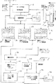
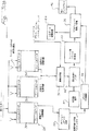
図1は、本発明の現時点における好ましい実施例が組み込まれた超音波映像システムの構成図である。
図2は、図1のトランスジューサの概略透視図である。
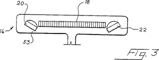
図3は、図2のトランスジューサの概略側面図である。
図4は、図2のトランスジューサの概略平面図である。
図5は、図1のシステムの一部分の概略図である。
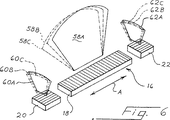
図6は、図2のトランスジューサが方位軸のまわりに回転させられる場合における画像領域の運動を示す概略透視図である。
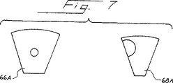
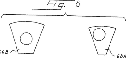
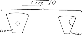
図7、8、9、及び、10は、トランスジューサの4つの回転位置において、図6のトランスジューサを用いて獲得された画像を示す概略図である。
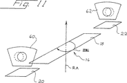
図11は、図2のトランスジューサの動作を示す概略透視図である。
図12は、図1のシステムによって生成された追跡画像領域の概略平面図である。
図13は、図1のシステムにおける運動の推定値の平均化を示す概略図である。
図14は、図1のシステムにおいて、画像化された器官の全体運動がどのようにして認識され、そして、無視されるかを示す概略図である。
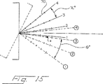
図15は、図2のトランスジューサが方位軸のまわりに回転させられる場合において、音波ラインの間における目標の運動を示す概略図である。
図16は、図15の未加工音波ラインデータの別の見取り図である。
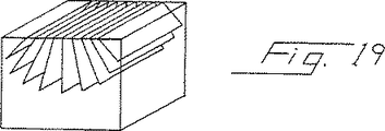
図17、18、及び、19は、三次元表現を形成するために、三次元において多重画像データフレームが相互に見当合わせされる方法を示す3つの概略透視図である。
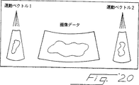
図20は、図1のシステムによって生成されたディスプレイの見取り図である。
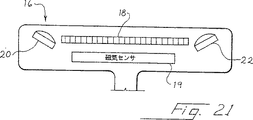
図21は、図1のトランスジューサの改造された機種の概略図である。
図22は、代替超音波映像システムの概略図である。
図23から26までは、本発明の選定された実施例における使用に適したクロスアレイを用いたトランスジューサの平面図である。
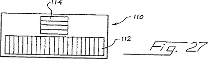
図27、及び、27aから27eまでは、本発明の選定された実施例における使用に適する代替トランスジューサの平面図である。
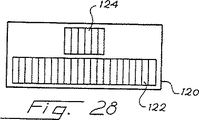
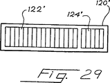
図28及び29は、本発明の選定された実施例における使用に適する別のトランスジューサの平面図である。
図30は、本発明の好ましい実施例が組み込まれた超音波映像システムの構成図である。
図31及び32は、図30の映像システムによって実施される定例過程のの流れ図である。
図33は、代替実施例の動作を示す概略図である。
図34から37までは、本発明の代替形式に含まれるファジー理論システムの動作を示すグラフである。
図38は、拡張された視界を形成するために2つのフレームを重み付けする方法を示すダイアグラムである。
図39及び40は、1つの単一ブロック運動推定システムに関する概略図である。
現時点における好ましい実施例の詳細な説明
図面を参照することとし、図1は本発明の現時点における好ましい実施例を含む超音波映像システム10の構成図である。以下の説明においては、先ず、システムの概観について述べ、次に、当該システムの選定された構成要素について詳細に説明する。
システムの概観
本システム10は、ビーム形成器システム/信号検出器12を有する。このビーム形成器システム/信号検出器12は、送信および受信両ビーム形成器を含み、マルチプレクサ/デマルチプレクサ14を介して超音波トランスジューサ18に接続されている。従来型の装置を含めて任意のあらゆる適当な装置は、エレメント12、14として使用するために容易に改作可能である。
超音波トランスジューサ16については、図2Aに関連して以下に更に詳細に説明することとする。ここに、トランスジューサ16は、3つの個別トランスジューサアレイ18、20、22を含むことが好ましいことに注意することが重要である。アレイ18は、目標のディスプレイ表現を作成するために使用される画像データ収集のために用いられる。本実施例におけるアレイ20、22は、追跡アレイとして作動するように画像データアレイ18に直角な方向に配置された小さい方のアレイである。本実施例における追跡アレイ20、22は、画像データフレームを復元用として適切に見当合わせすることを可能にするように、画像データアレイから画像データフレーム間の動きを推定するために用いられる。
ビーム形成器システム/信号検出器12は、アレイ18、20、22に励起信号パルスを送り、合計された復帰エコーを信号検出器に供給する。信号検出器の出力はスキャンコンバータ24に供給される。ビーム形成器システム/信号検出器12は、アレイ18、20、22に供給された励起信号のタイミングを適切に調整し、そして、受信済み信号を合計に先立って適切にタイミング調整及び位相調整することによってフェイズドアレイとして取扱う従来の方法によりアレイ18、20、22を操作する。スキャンコンバータ24は、以下に説明するように、好ましくは、3つのアレイ18、20、22によって生成される3つの画像を追加情報と共にディスプレイするように出力ディスプレイ26を制御する。
更に、スキャンコンバータ24からの走査変換された画像情報はデータ記憶システム28に記憶される。本実施例において、データ記憶システム28は3つの個別記憶アレイを含み、各記憶アレイは、アレイ18、20、22のうちのそれぞれの1つからの画像フレーム用データを記憶する。従って、画像データトランスジューサアレイ18からの画像情報は、画像データのフレームとして記憶アレイ30に記憶され、そして、追跡トランスジューサアレイ20、22からの画像情報は、それぞれ記憶アレイ32、34に、画像データのそれぞれのフレームとして記憶される。記憶アレイ30、32、34におけるデータのフレームは全て時間マーク付けされ、その結果、これらのフレームは相互に適切に組合わされる。この時間マーク付けは、例えば、リアルタイム時計情報、或いは、フレーム番号情報の形をとることができる。
記憶アレイ30における画像データのフレームはコンピュータ36に供給される。これらのフレームは目標のディスプレイ表現を形成するために用いられる。記憶アレイ32及び34に記憶された追跡画像フレームは、目標のディスプレイ復元を作成するために見当合わせされないが、その代りに、画像データ記憶アレイ30からの画像データの個別フレームの相対位置を決定するために用いられる。
画像データの連続するフレーム間の目標の動きを推定するために、追跡アレイデータ記憶アレイ32、34からの画像情報が運動推定器38に供給される。運動推定器38は、それぞれのフレーム間のトランスジューサ16の運動成分を推定するために、追跡トランスジューサアレイ20と追跡トランスジューサアレイ22からの一連の画像を比較する。運動成分の前記推定値はロジック40において平滑化され、次に、画像データ記憶アレイ30に記憶されている画像データの選定されたフレーム間運動の最良推定値を定義するベクトル値を算定する計算器42に供給される。次に、このベクトルは別の入力としてコンピュータ36へ供給される。
システム10において、エレメント28から42までは、リアルタイムで作動するように設計可能であり、そして、図20に関連して検討するように、運動ベクトルは出力ディスプレイ26上にディスプレイすることが出来る。一旦、データの全集合が獲得された場合には、画像データフレーム及びフレーム間変換ベクトルは、超音波映像システムと組合わされるか又は前記システムの外部に設置された専用コンピュータ36に伝達される。
コンピュータ36は、計算器42によって供給されたベクトルを適切に使用することにより、画像データ記憶アレイ30から選定された画像データのフレームを相互に見当合わせする。更に、あらゆる必要な補間が実施され、そして、画像データのそれぞれのフレームは三次元データ記憶装置44に相互に適切な決定位置に記憶される。コンピュータ36は、ディスプレイモードにおいて作動中である場合には、ディスプレイ46上に所要画像を供給するために、三次元データ記憶装置44から適切な情報を選択できる。例えば、画像データの平面に対応しない多種多様な平面を含む種々の平面における断面を求めることができる。更に、表面レンダリング及びセグメンテーションディスプレイも、必要に応じて生成することができる。
1つの作動モードにおいて、オペレータの直接手動制御の下に、画像データアレイ18の表面上の方位軸に沿った1つの単一軸のまわりに左右に平滑にスイープすることによってトランスジューサ16を回転させることが可能である。スイープの不完全性に対処する方法については次に説明する。三次元復元に際して、復元の品質は、位置的誤差の結果として極めて微妙に低下する。不完全な運動検出の結果としては「ぼやけ」でなく「歪み」を生じる。
超音波トランスジューサ16
図2−4は、超音波トランスジューサ16に関する3つの図を示す。図4に示すように、3つのアレイ18、20、22は、全てが共通支持エレメント53に取り付けられた、それぞれ対応するトランスジューサエレメント48、50、52集合を有する。トランスジューサエレメント48は方位軸Aに沿って配列され、画像データトランスジューサアレイ18は第1及び第2の端部54、56を規定する。追跡アレイ20、22は、方位軸Aを中心とする端部54、56のうちのそれぞれの1つの近くに配置される。トランスジューサエレメント50、52は、それぞれの追跡軸T1、T2に沿って配列され、そして、好ましい本実施例における追跡軸T1、T2は方位軸Aに実質的に垂直である。追跡アレイ20、22は、それぞれ、画像データアレイ18よりも短く、そして、装備するトランスジューサエレメント50、52の個数も少ない。トランスジューサエレメント48は、それぞれ、トランスジューサエレメント50、52のピッチの1/N倍の間隔を持つことが出来る。図3に示すように、追跡アレイ20、22は、画像データアレイ18に向かって内側を指すように位置決めすることが出来る。その代わりに、追跡アレイ20、22は、トランスジューサ16に対して好ましい縦断面を供給するために、アレイ18と同一平面に所在することが出来る。
画像データアレイ18は、例えば、円筒形の仰角集束レンズを備えた平らな線形アレイのような従来形であっても差し支えない。その代わりに、本アレイは全体的に平らであってもよいが、トランスジューサエレメントは仰角方向に焦点を結ぶように曲がっていても差し支えない。この場合、集束レンズは一切不要であるので、例えばポリウレタンのような非屈折性フィラーを使用することができる。レンズを使用すると否とに拘わらず、画像データアレイは、更に大きい視界を得るために、方位方向において曲がっていても差し支えない。追跡アレイ20、22は、通常、仰角方向において所要の焦点を結ぶためのレンズを有する。種々のレンズ又はアレイにおいて、平面が異なれば曲率も異なるので、好ましい平滑な形を得るために、トランスジューサ16上に非屈折性フィラーセクションが形成されても差し支えない。その代わりに、追跡アレイ20、22は、所要の形状の非屈折性ウィンドウが最上面に形成されるように曲げられても差し支えない。画像データアレイ18とアレイ20、22は、両方共、フェイズドセクタ、Vector▲R▼、直線、または、曲線であっても差し支えない。Bモード、カラードップラー、カラードップラーエネルギ及びこれらと類似の事象を含む全ての結像モードがサポートされる。2個のトランスジューサを用いる実施例においては、例えばAcuson製双平面V510Bトランスジューサのような従来型TEEトランスジューサを使用することが出来る。
図2に示すような画像平面を得るためには、図3及び4に示すトランスジューサの幾何図形的配置を使用できる。この実施例における画像データアレイ18の画像平面58は方位軸Aを通る。画像データアレイ18によって収集された画像データは、画像平面58内の走査線64に沿って配置される。トランスジューサアレイ20、22それぞれの画像平面60、62は、画像平面58を横断するように位置付けられる。画像平面58、60、62は、それぞれのアレイの中央画像平面であり、従って、1Dアレイに関しては唯一の画像平面であり、1.5Dアレイに関しては中央平面(即ち、仰角方向に方向付けられない平面)である。
簡素化のために、追跡アレイ20、22は、画像データアレイ18が使用するピッチと同じトランスジューサエレメントピッチであっても差し支えない。この方法は、3つ全てのアレイ18、20、22に対して同一ビーム形成器遅延を用いることを可能にする。ただし、多くの用途において、追跡アレイ20、22は、比較的少数の音波ラインを形成するために用いられる。運動検出が画像平面60、62の中心線の周辺に集中する場合には、特にこの傾向が強い。追跡アレイ20、22のために、ただ1つの狭い視界が必要である場合には、追跡アレイピッチは、例えば画像データアレイ18の2倍のピッチのように、更に粗くなる。
追跡アレイピッチを画像データアレイピッチの整数倍にすることにより、同一ビーム形成遅延を使用できるが、ただし、図5に示すように、適当なチャネルの接続を遮断することが必要である。図5において、追跡アレイ20のエレメント間ピッチは、画像データアレイ18のピッチの2倍であり、追跡アレイ20の連続したトランスジューサエレメント50は、画像データアレイ18のトランスジューサエレメント48に対する偶数または奇数信号ラインのみに接続される。極言すれば、各追跡アレイ20、22は僅か2個のトランスジューサエレメントによって構成可能であるが、当然ながら、達成可能な最高解像度が制限される。
ビーム形成器/信号検出器12とトランスジューサ16用ハウジングとの間には共通信号導体を使用することができる。前記ハウジングにおいては、例えば、Supertex社(Sunnyvale、カリフォルニア)から入手可能であり、ファミリ称呼HV2xxを有するこの種の装置のような高圧アナログスイッチ又はマルチプレクサにより、信号導体とトランスジューサエレメント48、50、52との間で個々の信号が経路指定される。
図6から11までは、画像データアレイ18によって生成された画像の間の動きを推定するために、追跡アレイ20、22によって生成された画像を用いる方法を示す概略図である。図6は、トランスジューサ16の3つの個別位置の透視図を示す。トランスジューサ16のこれら3つの個別位置は、方位軸のまわりにトランスジューサ16を回転させることによって求められる。画像データアレイ18が方位軸Aのまわりを回転するにつれて、画像平面58A、58B、58Cは扇風機と同様の態様において回転する。従って、図6の各画像平面58A、58B、58Cは、三次元空間のそれぞれの個別平面に配置される。
これとは対照的に、各追跡アレイ20、22に関する画像平面60A、60B、60Cと62A、62B、62Cは、トランスジューサ16が方位軸Aのまわりで回転するにつれて、共通平面状態を維持する。トランスジューサ16が回転するにつれて、画像平面60A、60B、60Cと62A、62B、62C内における実際の結像領域は、方位軸Aの回りに回転する。多くの用途において、画像平面58A、5BB、58C内の結像領域は、画像平面60A、60B、60C内の結像領域又は画像平面62A、62B、62C内の結像領域に対して重複または交差しない。この配列は、以下に検討するように、混線及び他の妨害問題を軽減することができる。
図7から10までは4組の画像を示す。各組は、画像データアレイ18からの画像66A、B、C、Dおよび追跡アレイ20、22の1つからの対応する画像68A,B,C,Dを含む。この場合、目標は球体であり、そして、画像66、68は、球体が両方の画像66、68内に現れるように交差する。画像66A、B、C、及び、Dに示すように、トランスジューサ16が方位軸のまわりに回転するにつれて、前記球体の種々の断面がディスプレイされる。画像66A及び66Dに示す断面は、球体の縁の近くで切り取った比較的直径の小さい円盤を示し、画像66B及び66Cは、球体の中心の近くで切り取った比較的直径の大きい円盤を示す。従って、画像66A、B、C、及びDに示す円盤は、当該画像の移動平面にしたがって直径が異なる(図6参照)。対照的に、全ての画像68A、B、C、及び、Dは、同寸法の円盤を示す。図6に関連して既に検討したように画像68A、B、C、及びDの平面は同じ状態を維持するので、これらの画像内にディスプレイされる円盤は、寸法が一定の状態を維持するが、画像平面を横断して移動する。円盤が或る画像からその次の画像へ移動するにつれて、その円盤の位置は、画像68A、B、C、Dの画像平面内におけるトランスジューサ16の運動成分の測定値を提供する。
トランスジューサアレイ20、22の画像平面が画像データアレイ18の表面に垂直でない場合には(例えば、図3に示すように、追跡アレイ20、22が内側に向けられるので)、画像の範囲と画像データアレイ18に垂直な物理的な深さとの間の差を考慮するためにコサイン(補正係数を使用することが好ましい。
トランスジューサ16の重要な利点はそれぞれ画像データアレイ18の隣接端部54、56の近くに配置された2つの追跡アレイ20、22を有することである。この配列は、合成回転の評価を可能にする。図11において、トランスジューサ16は、図に示すように方位つけられた回転軸RAのまわりに回転させられる。図11において、実線の円は、第1の時点における目標の画像を表わし、点線の円は、回転軸RAのまわりに回転した後の、次の時点における目標の画像を表す。この状況においては、画像が画像平面60、62内において反対方向に動くことに注意されたい。2つの追跡アレイ20、22から別々に決定された運動成分を比較することにより、トランスジューサ16に対する目標の実際的な回転を決定することができる。必要に応じて、トランスジューサ18には、例えば図21に示すような磁気センサ19または加速度計のような位置、配向(オリエンテーション)或いは両者を含ませることが出来る。センサ19は、次に詳細に説明する運動の検出方法を補足または支援するために使用しても差し支えなく、また、Keller米国特許5,353,354に開示されたタイプであっても差し支えない。
ビーム形成器システム/信号検出器12
トランスジューサと16が実質的に方位軸Aのまわりに回転させられるにつれて、画像データアレイ18及び追跡アレイ20、22は順次操作される。アレイ18、20、22が個別にアドレス可能である場合、エレメント12内の送信ビーム形成器は、それぞれのトランスジューサエレメント48、50、52に、適切に時間調整および位相調整された励起信号を送る。一実施例において、画像デ一タアレイ18からのデータの1つのフレームが収集され、次に、追跡アレイ20、22からのデータのフレームが収集される。その代わりに、送信ビーム形成器は、画像データアレイ18と追跡アレイ20、22との間、個々の走査線間、或いは、走査線のグループの間において交互作動しても差し支えない。アレイ18、20、22の画像平面が非交差的である場合、特に画像データアレイ18が追跡アレイと異なる周波数によって励起される場合には、交差アレイ干渉の危険性は小さい。従って、パルス繰返し率(一般に、継続する走査線間の人体において超音波信号を減衰させるために必要な時間によって制限される)を増大しても差し支えない。
幾つかの用途においては、アレイ18、20、22は、送信ビーム形成器へ共同接続しても差し支えない。一般に、画像データアレイ18に関する結像必要条件は、追跡アレイ20、22の場合とは実質的に異なる。画像データの品質は高水準に維持されなければならないが、追跡データは、信頼できる追跡を可能にする程度の品質であれば十分である。アレイ18とアレイ20、22との間の或る程度のケーブル導体を共用することによりコストを節減することが可能である。一般に、画像データアレイ18の端部近辺のエレメントは中心エレメントよりも重要度が小さいので、最も共用に適する。
アレイ18、20、22間の干渉を軽減するためには、画像データアレイ18のエレメント48から追跡アレイ20、22のエレメント50、52までの経路を公知の疑似ランダム状態にジャンブルすることが好ましい。一方の組のアレイ(画像データアレイ18または追跡アレイ20、22のどちらか)が、あらゆる所定の走査線においてコヒーレントに操作されようにビーム形成器遅延をソートするために、エレメント12はジャンブリング方式を用いる。ケーブルジャンブリングによって、もう一方の組のアレイは非干渉的に操作される。最適ジャンブリング方式は、定例的な実験によって決定しても差し支えない。
混線は、周波数コード化および電圧水準技法によって更に軽減可能である。追跡アレイ20、22は、例えば2、3センチメートル程度に減少された画像深度を以て、従って、例えば10MHz程度の高周波により作動可能である。画像データアレイ18は、比較的レンジが長く、例えば5MHz程度の比較的低い周波数において作動することにより、混線を軽減することが出来る。トランスジューサエレメント48、50、52は、適切な周波数を選定するような厚さに形成することが出来る。更に、検出のために望ましい周波数帯を選定するために、エレメント12にバンドパスフィルタを使用することも出来る。
電圧レベルは、2組のアレイ18、20、22の間で同じでなくても差し支えない。例えば、追跡アレイ20、22が選定されている場合、特に、追跡アレイ20、22が効率的に作動するために高い方の電圧が必要な場合には高い方の電圧を使用することが出来る。この場合、画像データアレイ18が選定され、電圧レベルが引き下げられると、追跡アレイ20、22は比較的小さい信号を放出する。
図22は、システム10と同じ多数の構成要素を使用する代替システム10’を示す。システム10’は、アレイ18、20、22が、ビーム形成器/信号検出器12’、12”により、異なる周波数において同時に操作されるという点が異なる。各々の場合において、問題のバンドパスを分離するために、それぞれのバンドパスフィルタ13’、13”が装備される。既に述べたたように、追跡アレイ20、22は10MHzにおいて作動可能であり、画像データアレイ18は5MHzで作動可能である。既に検討済みのジャンブルされたケーブル経路を、妨害を軽減するために使用しても差し支えない。バンドパスフィルタ13’、13”は、ビーム形成された信号用に使用できるが、実際には図22に示す構成が好ましい。
トランスジューサ16が、方位軸Aのまわりに回転することによってスイープされる場合、画像データアレイ18用の好ましいフォーマットはセクタフォーマットである。セクタフォーマットにおいて得られた音波ラインデータは、走査変換なしの相関過程において都合よく使用できる。その理由は、例えば、線間角度増分(インクリメント)、法線に関する線角度(図15参照)、及び、サンプル間レンジ増分(インクリメント)に関して既知であれば、直角座標における純粋な回転は、適当に選定された円筒座標系における角座標の変化として表すことが可能であることに因る。
運動推定器38
運動の検出は、例えば、画像平面60、62における特定の認識可能な特徴のディスプレイデータ上に線を描き、次に、後続する次のフレームにこの動作を繰り返して実施することにより手動で実施可能である。本システムは、フレーム間の動きを表すベクトルを生成するために、連続するフレームに関する線位置の追跡を保持することが出来る。
更に良好な方法は、追跡アレイ20、22によって得られる画像データに関する相互相関または類似の方法を用いるフレーム間運動のコンピュータ解析を使用することである。この種の技法(ここでは全体的に相関技法と称する)は、過去において、血液流の追跡用として用いられた。これらの方法は、認職可能な特徴がディスプレイ領域に所在することを必要とせず、超音波小斑点データのみを用いて十分に機能可能である。小さい斑点(スペックル)は、超音波画像における自然発生現象であり、組織内の小さい散乱対象からの反射波の可干渉性の結果である。
Bohs及びTrahey共著「血液流及び組織運動の角度に無関係な超音波結像のための新規な方法」(IEEE議事録、Biomed.Eng.38、IEEE 頁280−286、1991年3月)に記載された相互相関及び絶対差合計法を含むあらゆる適当な相関技法が使用出来る。相互相関は、2組のデータが最も良くマッチする変換に関する探索データの各種変換に関して順次に求められる乗算和を使用する公知の数学的演算である。絶対差合計法は、コンピュータ的な一層簡単な相関技法であるが、実質的には同様の効果が得られる。データ集合は一定でない量毎に変換される。各変換毎に、各集合においてそれぞれのデータ値が差し引かれ、絶対差の和が算定される。特定の変換によってゼロに近い絶対差の和が得られた場合には、データの集合が関連変換によって調整された可能性が高い。調整を達成するために必要な変換は、それぞれの追跡アレイに最も近い画像の側におけるそれぞれ2つのフレーム間における運動の表示である。以下に説明するように、当該画像の他の部分における運動は、画像データアレイ18の方位に沿った追跡アレイ及び線形補間両技法において検出された運動を用いて評価可能である。
どちらのタイプの相関においても用いられるデータブロックのサイズは最適化に関わる問題である。ブロックが大きくなれば、間違ったマッチングの発生する可能性は減少するが、一層長い計算時間を必要とする。検出可能な最大フレーム間変位は、ブロックサイズによって制限される。一般に、探索は、ブロックサイズの半分に相当するプラス、マイナス分まで実施される。一例として、+−8画素の最大変換を検出するためには16x16画素ブロックが使用可能である。
運動推定器38は、運動を決定するために、アレイ30、32、34に記憶されたデータのフレームに基づく任意の効果的技法を用いることができる。運動推定は、フレーム全体、或いは、フレームの部分に基づいても差し支えない。前記の部分が用いられる場合、これらの部分は、画像において明確に定義される特徴に対応するように選定することが出来る。この方が一層効率的である場合には、時間を節約するために、利用可能なデータの間隔を設けた部分集合に関して運動推定を使用しても差し支えない。例えば、サンプルが0.5mm間隔で利用可能であるが、最適化された運動検出が1mm間隔に基づいて実施可能である場合には、利用可能なデータの部分集合にのみ基づく運動検出を実施することによって時間を節約することが出来る。
運動推定のために使われる追跡画像データは、少なくとも下記項目を含む多数の形式(フォーム)のうちの任意の1つを用いることが出来る。
1.出力ディスプレイにおける隣接画素(実際の音波ラインデータから補間された)。
2.更に大きいグリッドから選定された画素、例えばN番目毎の画素。
3.画素のグループの平均値、例えば、4個の隣接画素のグループの平均。
4.プリスキャン変換ビーム形成器音波ラインデータからのサンプル。
音波データのビーム形成器出カラインは、極フォーマット或いはカーテシアンフォーマットであっても差し支えない。これらのデータラインと伝播の物理的ラインとの間の関係は公知であるので、これらの音波ラインから導出されたサンプルは、運動検出に使用可能である。
図15は、音波走査ラインデータに関するフレームN及びN+1における目標の位置を示す概略図である。図15の基準記号70は、測定が行われた個々の点に関して用いられる。これらの点は、走査ラインに沿って個々の間隔を以て配列される。図16は未加工の音波ラインデータ(走査変換前)を示し、図において、各行はそれぞれの走査ラインを表し、それぞれの範囲における測定点が示される。
図15及び16の「+」記号は、N及びN+1の両フレームに関する目標位置のために用いられる。運動推定器38は、フレームN及びN+1に関して作動する場合、目標は走査ライン1から走査ライン3に移動し、レンジは起点から4個のサンプルインタバルにおいて一定状態を維持したことを検出する。走査ラインの角度分離間隔はX度であり、運動ブロックの中心における隣接点70間距離はPmmに等しいので、基礎的な幾何学的関係は、横方向のオフセット(偏り)は「+8PsinXsinΘ」に等しく、深さ方向の偏りは「−8PsinXcosΘ」に等しいことを証明するために使用出来る。ここに、Θは、度で表した運動検出ブロックの中心と走査ラインの起点から出発する法線との間の角度であり、追跡アレイはセクタフォーマットにおいて作動中である。これらの計算は概略的であるが、未加工の音波ラインデータが運動推定器38において使用できる方法を実演する。
音波ラインデータが運動推定器において使用される場合には、ディジタル化済みRF、ディジタル化済みIF、ディジタル化済みベースバンド、または、整流およびローパス濾波されたエンベロープ検波済み信号に対応することが出来る。エンベロープ検波済み信号の一例として、Bモードデータを使用できる。音波ラインデータ信号は、実デジタルサンプル、或いは、複素数(I、Q)データサンプルであるものとする。
現時点における好ましい実施例において、運動推定器38において用いられる方法は、1つの画素ブロックにおける絶対差の和が16x16画素に等しいことに依存する。効率の観点から、専用集積回路を使用することが便利である。LSIロジック64720集積回路は、30分の1秒間に396ブロックのレートにおいて、18x18運動検出を実施するように設計されている。これらの回路は、更に高いスループット又は更に大きいブロックサイズ寸を達成するように組み合わせることが可能である。ブロックサイズが8x8画素に縮小された場合には、更に高いレートが可能である(1/30秒間に4500ブロック)。この集積回路は、大量生産におけるコスト面において有利である。同様に、代替集積回路も使用可能である。その代りに、例えばTexas Instruments製TMS 320C80のような適切にプログラムされた汎用プロセッサを用いて動作全体を実施可能である。
例えば、画像平面58が画像平面60、62の垂直軸に対して位置調整されるように、アレイ18、20がアレイ16に対して位置調整されることが好ましい。
従って、画像平面60、62の中心線に対する運動は、画像平面58の相対運動を決定するために使用できる。データブロックは、中心線に沿って配置されるように定義される。
厳密には追跡アレイ当たり2つの運動検出動作だけが必要である。ただし、画像の種々の部分全体に亙って(必ずしも中心線上とは限らない)多重追跡動作を実施することにより、本方法の精度を一層高くすることが出来る。例えば、図13に示すように、適合するように引いた滑らかな直線は、検出しようとする運動成分の多数の推定値の平均値を求めるために使用できる。図13において、破線による矢印は適合させた運動成分を表し、実線による矢印は実測された運動成分を表す。多数の測定値の平均値を求めることにより、一層信頼度の高い推定値が得られる。この平均値は、運動成分ベクトルの振幅と角度両方に関して使用出来る。
更に、近傍推定値と根本的に異なる運動推定値は不正確として廃棄可能である。図14に示すように、追跡アレイのうちの1つの画像は、画像の大部分の小斑点によって示される運動と異なる矢印74によって示される大きい運動を有する器官72を含み、この場合、器官の大きい運動は無視することが出来る。短い方の矢印76によって示される運動の残りの推定値の平均値は、当該フレームの運動の推定値として使用することが出来る。適切な一方法は、運動ベクトル(長さと方向)を量子化し、次に、最も一般的に発生する量子化済みの長さと方向を見付けることである。次に、許容帯域バンド内、即ち、最も一般的に発生する値の30%以内の実際の(量子化されない)ベクトルが選定され、そして、所要の推定値を生成するために平均される。
更に、絶対差の和計算において、平均和(最小和の値を除去した後)に対する最小和の比率は、画像運動検出の品質の標識(インジケータ)として使用できる。最小和が平均に近い場合、計算は、誤り、即ち、間違って検出された運動の影響を受け易い。LSI 64720集積回路が用いられる場合には、誤り値の和出力は低品質結果の標識(インジケータ)である(誤り値の和が大きいことは結果が低品質であることに対応する)。
追跡の質が低いことは、運動の推定値を比較することによっても検出可能である。運動の隣接推定値または連続推定値が相互に類似していないことは、運動推定の質が低いことを表示していることがあり得る。勿論、上記の方法の2つ又はそれ以上を組合わせて使用しても差し支えない。
小斑点(スペックル)パターンは、運動が起きると、急速に変化する。特に、仰角スライス位置が移動した場合には、スペックルパターンが変化する。その理由は、小斑点散乱体は、画像平面内に残って画像平面と平行に移動することなく、画像平面に対して入ったり出たりして移動することに因る。従って、多くの場合に、トランスジューサ16の移動につれて、頻繁に運動推定値を求めることが好ましい。推定値の正確な周波数は、運動検出問題の規模に依存し、オペレータが実施する運動の速度、スライス位置を維持するオペレータの能力、及び、小斑点目標の性質(組織のタイプ及び超音波周波数の関数である)に関係する。
一例として、画像データアレイ18からの30個の画像データフレームは、所要の3D復元のために十分な映像データを提供することが決定される。ただし、各選定済み画像データフレームの間で5件の運動推定を実施すること、及び、画像データフレーム間の正味運動を算定するためにこれらの推定値を合計することが好ましい。累積的な誤りは最小限化されるべきであるので、この結果を達成するための1つの方法は、運動検出動作を過剰標本抽出し、そして、画素サイズに起因する計量効果を軽減するために結果を平均することである。この方法を用いると、例えば、画像データアレイ18の各フレームに対して追跡アレイ20、22の各々から5個のフレームが存在する。
小さな運動検出値の和に基づいて実施する場合、運動検出が最良機能することが多いが、フレームNとフレームN−Mとの間の運動検出を使用することが重要である場合がある。ここに、Mは、例えば10のように、1より大きい整数である。原則として、この方法は、累積誤差を訂正するために使用できる。ただし、この種の大きい運動が正しく推定される確率は小さい。従って、Mの値は最適化に関わる問題である。
仰角スライスは小斑点の質及び安定性に影響するので、レンズの仰角焦点において運動を追跡することが好ましい。その代わりに、小斑点の依存性が仰角焦点において敏感であり過ぎる場合には、その部分を避けることが好ましい。一層正確なデータを対象とすることにより正味の精度を最大化するための平滑化操作に際して、検出された運動には、変動する重み付けを適用することが好ましい。仰角焦点調整されたアレイ(1.5Dアレイ)を使用するか、或いは、最良の結果を提供するための実験に際しては、焦点調整しないアレイを使用することが好ましい。
運動検出のために用いられるデータは多くの形式であっても差し支えない。エンベロープ検波された走査変換済みデータは簡単な設計に主眼を置いた選定であり、現時点においては好ましい形式である。代替案には、走査変換前にエンベロープ検波されたデータ及びエンベロープ検波前におけるRF又はベースバンドビーム形成器出力信号が含まれる。
何らかの理由により、追跡データ画像における特定の領域が最良の運動検出を提供するはずであるという特定の意向をユーザが持つ場合には、対象とする当該領域をユーザが選定することも可能ある。例えば、ユーザは、運動検出のための領域として、移動中の血液量を使用しないように選択することも可能である。
画像データの収集に際して好ましいディスプレイを図20に示す。図20において、画像データアレイ18からの画像は、スクリーン上の中心部に示され、追跡アレイ20からの追跡画像22は、スクリーンのそれぞれの側部に示される。好んで運動検出はリアルタイムに実施され、算定済みの運動がリアルタイムで発生するにつれて当該運動を指示することにより、検出された運動がディスプレイ上に呈示されることが好ましい。このディスプレイは、図20に示すように、運動ベクトルの形式をとることが出来る。代案として、検出された運動の数値的な測定結果をディスプレイすることも出来る。これらのディスプレイは、スイープ中のトランスジューサの相対位置を示し、従って、所要の角運動が何時完成するかに関する表示をオペレータに提供し、更に、運動検出システムが適切に作動しているかどうかの表示も提供する。その代わりに、画像データは、追跡画像無しで、或いは、検出された運動のディスプレイ無しでディスプレイされることも可能である。システムによって算定された運動ベクトルが追跡の質が低いことを表示する場合には(例えば、1つの単一フレーム内または連続フレームの間の算定済み運動ベクトルの誤った変化)、当該システムは、例えば、警報、或いは、点滅又はビデオメッセージの反転のような視覚的プロンプトとして、オペレータに再開始をプロンプトすることが出来る。
必要に応じて、システム10は、最適スイープレートを達成することによってユーザを支援するようにプログラムされることが可能である。多くの場合に、運動推定器を最適使用するためには、スイープレートの最適化、即ち、スイープレートは、受け入れ不可能な誤りの累積を回避するために十分な程度に大きく、また、運動推定器の運動範囲内に留どまる程度に小さいことが必要とされる。オーディオ又はビデオどちらのプロンプトを使用しても差し支えない。
例えば、±8画素運動を検出するために運動推定器18を適用する際に、例えば、推定行為当たり4画素の運動のように、スイープレートが概略正しい場合には、当該システムが断続音を発生することも可能である。推定運動が小さ過ぎる場合には(例えば、2画素未満)、断続音の代わりに低い連続音が用いられ、スイープレートが更に遅くなる場合には、前記の連続音は更に低くなる。逆に、推定運動が大き過ぎる場合には(例えば、6画素を超過)、断続音の代わりに高い連続音が用いられ、スイープレートが加速された場合には、前記の連続音は更に高くなる。
適当な視覚プロンプトには、長さの変化する矢印が含まれ、この矢印は、スイープレートを更に速くするようプロンプトするには更に長くなり、スイープレートを更に遅くするようプロンプトするには更に短くなり、最適スイープレートを示すためには強く輝く。
別の方法は、運動成分を推定するように関連付けられたフレームの時間間隔を選択するように運動推定器をプログラムする方法である。適応可能な方法によってこの間隔設定を適切に選択することにより、測定された運動成分を、広範囲に亙るスイープ速度の最適範囲内に保持することが出来る。例えば、相関のある追跡フレームの各対の間に多くの未使用追跡フレームが有り、8画素が最大検出可能運動である場合には、相関のある追跡フレームの各対の間の未使用追跡フレームの個数は、必要に応じて、検出された運動を4から6画素までの範囲内に維持するように、リアルタイムで増減させることが出来る。
低品質の運動推定は低水準の重み付けするか或いは完全に除去することが出来る。低品質運動推定を選定するための1方法は、先ず、全ての運動推定に1つの曲線を適合させる(長さと角度の両方)。次に、個々の運動推定値を適合した曲線と比較し、次に、例えば30%のスレショルド量以上に曲線から偏った運動値推定値は低質運動値推定値とみなし、運動推定値の収集から削除される。次に、残っている運動推定値のみを用いて曲線適合作業が繰り返される。運動推定値の或る部分、例えば20%が低晶質推定値として分類された場合には、当該作業が放棄され、ユーザはスイープを繰り返すようにプロンプトされる。
一般的に、連続する画像の相対位置を関係づける運動成分の決定のみが必要とされることがしばしば起きる。必要に応じて、図12に示すように、決定済み運動ベクトルに垂直な線を引くことによって回転軸を決定することも可能である。これが行われると、運動ベクトルの長さは、当該運動ベクトルの回転軸からの距離を表示する。
厳密に言えば、2つの追跡アレイ20、22を持つことは必要でない。ただし、2つの追跡アレイを使用する場合には、不純な回転(画像データアレイ18の一方の端がもう一方の端よりも余分に回転した場合)を扱う能力は実質的に向上する。更に、多数の追跡アレイが用いられ、各追跡アレイにおける種々の範囲に関する運動が決定された場合には、各追跡アレイ上のレンジ方向における全ての中間点に関して適用される回転の中心を見付けるために、補間を適用しても差し支えない。
追跡アレイは画像データ平面のどちらかの側に所在し、追跡アレイに関する画像データ平面の正確な幾何図形的配置は既知であるので、画像上の全ての点に関する正確な画素変換を算定するために画像データアレイ方位軸に沿って線形補間を行うことが可能である。
一般に、運動推定値は、直線に沿うか、或いは、直角格子を横断して収集される。アレイの幾何図形的配置及びアレイからの直線音波ラインの伝播に関する制約に起因し、深さの関数としての運動ベクトルの理論的作動状態は或る種の制約を満足させなければならない。特に、運動ベクトルの長さは、深さと共に線形変化しなければならない。これらの制約条件は、推定された運動における誤りを減少させるために使用できる。例えば、一連の運動推定値は、深さの関数として求め、次に、運動推定ベクトル(長さと角度)に変換できる。次に、長さ成分に関する実際のデータと最も良く適合する線を決定するために公知の方法を用いて直線を適合させる。次に、第2の直線が、角度または方向成分に関して実際のデータに適合される。これらの適合線(長さと方向によって構成される)は、期間中それら以外の運動ベクトルを導出するために用いられる位置以外の中間位置における三次元的復元に際して、方位方向に沿って線形補間可能である。
患者とトランスジューサ16が緒にゆっくり移動する場合には、患者に対するトランスジューサ16の相対位置が大局的に維持される限り、結果として必ずしも性能の損失が生じるとは限らないことに注意されたい。
運動推定を更に改良するために、ECGサイクル又は呼吸サイクルの選定済み部分に対応する画像のみを利用することが望まれることもあり得る。ECGゲート作用および呼吸ゲート作用は、両方共、画像の三次元復元において公知である。例えば、McCann等著「心臓学のための多次元超音波結像」頁1065参照のこと。ECGゲート作用を用いると、ECGパルス後の一定最大継続期間に亙りウィンドウが選定される。呼吸ゲート作用を用いると、超音波走査のための短い期間に亙って患者の呼吸を止めておくように患者に要求することが簡単である場合が多い。その代りに、胸郭運動は変位センサを用いて記録可能であり、呼吸サイクルの一部分に関するデータを選定することが出来る。
運動推定を最適化するために、他の様々な技法が使用出来る。画素を一層繊細にするために補間することによって、精度を改良することが出来る。データのノイズは、ローパスフィルタ又はメジアンフィルタを用いて除去可能であり、輝度への電圧レベルのマッピングは、運動推定用として最適化可能である。一般に、追跡アレイ20、22において対数圧縮が用いられ、この対数圧縮は、画像データアレイ18からの画像データ用に用いられる対数圧縮とは無関係に最適化可能である。利用される特定のマッピングは、オペレータの意図によって大幅に変えることができる。多くの場合、運動検出は、オペレータによって画像データ用に用いられるマッピングとは異なるマッピングを用いることにより、最も能率的に機能すると推測される。必要に応じて、システム10は、高品質の運動検出を提供するマッピングが見付かる時まで、追跡アレイ20、22からのデータに関して内部的に用いられるマッピングを変えることが出来る。
三次元ボリューム充填コンピュータ36
所要の三次元復元を提供するための画像データフレームの位置調整用として多くの方法を用いることが出来る。その一例を図17から19までに略図的に示す。この例において、復元前における画像データフレームを略図的に図17に示す。中央平面用の画像データフレームは、図18に示すように、ボリュームの中心に対して位置調整された平面に挿入される。図19に示すように、連続する画像データフレームは、この中心から外側に向かって、該当するそれらのXYZ位置に挿入される。一旦、全てのフレームが挿入されると、補間されるべき点のまわりの立方体として配列された8個の最も近い既知データに依存する三次元線形補間技法を用いて中間点が算定される。この種の三次元操作技法は公知であり、従って、ここでは詳細に説明しない。
1つの方法は、ビューレット・パッカード・ジャーナル1983年10月号30−34ページにLeavittによって記載された三次元用に改作された走査変換補間技法を使用することである。Leavittによって示されたこの技法は、二次元平面におけるデータを用いて作動する。三次元におけるデータは、2つの連続した二次元操作において取り扱われる。画像平面データは、Leavittが示すように、三次元走査変換の必要条件に適合する画素間隔を用いて、走査変換してから補間することが出来る。次に、直交二次元走査変換は、各方位位置において、垂直方向のボリュームを充填するように実施可能である。Leavitt技法は、連続する二次元画像に関して回転軸が正しく位置調整されているものと仮定する。この仮定が成立しない場合には、他のボリューム的復元方法が使用できる。種々の適切な復元方法が公知であり、従来型の磁気センサを基調とするシステムと共に用いられる。
密接し過ぎた連続フレームが検出された場合には、幾つかのフレームデータを廃棄しても差し支えない。非常に多数のフレームが存在する場合には、所要の均一間隔に近い間隔のフレームのみを保持することが可能である。例えば、復元のための所要間隔が2度であり、0、1.2、2.1、2.8、3.9度においてデータが獲得された場合には、フレーム1、3、及び、5は、ほぼ0、2、及び、4度に配置された概略的に正しいフレームであると仮定される。近似に起因する誤差は重要でなく、復元を簡素化することが出来る。
変換検出技法
更に、画像データフレーム内の運動成分も上記の技法を用いて検出可能であることに注意されたい。この運動成分は方位軸に平行であり、追跡アレイを用いて検出された方位軸に垂直な運動に加えることができる。画像データアレイ18からの画像データは仰角平面の運動に起因して有意に移動するので、この平面における運動検出は過剰に標本抽出することが好ましい。図14に関連して既に検討したように、復元に際しては、実測した正味の運動が適用されることが好ましい。
更に、変換に際してトランスジューサ18が方位軸に沿って動かされた場合には、既に検討した回転スイープの場合とは対照的に、画像データフレーム平面内における運動が検出可能である。この方法を用いると、トランスジューサ16を回転させることなく、トランスジューサ16を方位軸に沿って軸方向に移動させることによって拡張された視界が提供可能である。この種の線形変換における追跡のみに関心がある場合には、追跡アレイ20、22は不必要である。
ここで使用される場合には、拡張された視界とは、トランスジューサアレイがその方位軸に沿って軸方向にシフトされるにつれて、トランスジューサアレイからの画像データを記憶するシステムを意味する。次に、拡張視界画像を形成するための復元用として、方位軸に沿った各種の位置におけるアレイからのデータが見当合わせされる。
上記の拡張視界は、追跡アレイ20、22のうちの一方、または、画像データアレイ18のいずれかからのデータによって復元可能である。更に理論的には、画像データアレイ18は画像の品質に関して最適化されるので、画像データアレイ18が用いられる。次に、画像データアレイは、その方位軸を運動の線に平行に方向付けした状態において目標組織に関して変換される。上記の技法を用いる画像運動の検出は、画像データアレイ18からの画像データに関して実施される。
アレイ18からの画像データによって構成される連続フレームは、画像データフレーム間の運動を定義する変位情報と共に記憶される。
一旦、画像フレームのスイープが完了すると、組織方向において相互に位置調節された画像データフレームのうちの連続する幾つかを見当合わせ(整合)するために、変位情報が用いられ、最も最近獲得された画像データフレームから始動する。次に旧い方の画像データは新規な方の画像データの上に重ねられる。一般に、旧い方のデータの大部分は新規な方のデータと殆ど正確にマッチするが、新規な方の画像位置においては獲得不可能であって旧い方の画像位置において獲得されたデータを表す重複しない小さい領域が存在する。新規な方のデータの上に旧い方のデータを記入する際には、重複しない領域だけが記入される。この方法によれば、冗長な画像記入動作が除去される。次に、この手順は、画像データのフレームに関して早い方から順に、当該スイープ内の全てのフレームがディスプレイ用として再度アセンブルされるまで継続される。
記憶の限界を越えて記入する試行が実施される可能性の有る状況が存在する。この状況が検出された場合には、利用可能なスクリーンメモリに適合するように小さくするために画像データを基準化することが可能である。基準化(スケーリング)は、コンピュータグラフィックスの分野で公知のように、幾何図形的変換および補間を使用する新規な記憶装置へ画素を再マッピグすることにより、達成可能である。
次に示す方法は、運動検出を強化するために、単独或いは種々部分的に組み合わせることによって使用することが出来る。
1.周波数選択。一例として、全てのN番目毎のフレームが運動検出に用いられる。運動を検出する能力を強化するような方法においてスペックルパターンを改変する目的で、全てのN番目毎のフレームに関して、画像データアレイ18のトランスジューサエレメントを励起させるために異なる周波数が用いられる。相対運動だけが必要とされるので、全てのN番目フレームにおいてより高い解像度のスペックル(小斑点)データを獲得するには、より高い周波数を使用することが好ましい。より高い周波数は浸透深度の減少と関連しているが、既に検討したように運動検出のためには浅い目標データだけが必要とされるので、この事実は欠点とはならない。その代わりに、より高い周波数は、小斑点(スペックル)を位置に関して非常に敏感にする。画像の仰角平面に対して出入移動する特徴の追跡不能に起因して運動検出の失敗原因となる場合には、この事実は好ましくない。この場合には、運動検出フレームに対してはより低い周波数を使用することが好ましい。
2.帯域幅調整。上記のように、この場合、帯域幅、並びに、或いはその代わりに、中心周波を運動検出に関して最適化することによって、選定された幾つかの画像データフレームは運動検出のために最適化可能である。
3.仰角集束。1.5次元アレイが用いられる場合、幾つかのフレームは画像データ収集に関して、また、他のフレームは運動検出に関して最適化するために、スイープに際して、仰角集束を調節することが出来る。例えば、仰角運動の影響を軽減するために、運動検出用に使用されるこれらの画像データフレームにおけるビームを僅かに集束解除することが好ましい。
4.方位角集束。同様に、運動検出の質を著しく低下させることなく運動検出を安定化するために、選定されたフレームに関する方位において、音波ビームを僅かに集束解除することが好ましい。
上記の4つの方法のうちの任意の方法を使用する場合、運動検出に関して最適化された画像データフレームはスクリーン上にディスプレイする必要がない。その代りに、結像に関して最適化された画像データフレームに限り使用可能である。
低速スイープ期間中は冗長データ(組織内の個々の位置に関する多数のデータポイント)が存在するので、冗長な運動検出データを収集するために、異なる周波数、帯域幅、及び、集束方法の利用を混合することが好ましい。多数の冗長データが収集された後において、更に信頼度を上げ、誤差に対して影響され易さを軽減する運動推定値に到達するために、当該データを平均することが出来る。
一例として、アレイが1秒当たり2mm移動し、有用に解像可能であるために必要とされる最小の運動は0.5mmであり、フレームレートは1秒当たり40フレームであるものとすれば、有用な運動検出が獲得され得る時点の間に10個のフレームが存在することになる。同様に、これら10個の運動検出フレームの各々に対してただ1個の画像データフレームが必要である。最初の20個のフレームについて検討することとし、フレーム1と11は、ユーザが決定した中心周波数及び帯域幅を用いて収集された画像データである。フレーム3と13は第1の代替中心周波数及び帯域幅を持つ運動検出フレームである。フレーム5と15は第2の代替中心周波数及び帯域幅を持つ運動検出フレームであり、フレーム7と17は第1の代替中心周波数及び第2の代替帯域幅を持つ運動検出フレームである。フレーム9と19は変更した集束方式を用いる運動検出フレームである。フレーム2、4、6、8、10、12、14、16、18、及び、20は、これらが画像フレームであるかのように獲得されたフレームであり、そして、ディスプレイされるが、追跡用として記憶されるか、或いは、使用されることはない。次に、それぞれフレーム11、13、15、17、及び、19に関するフレーム1、3、5、7、及び、9から検出された運動は、他の推定値と有意に異なる運動推定値を除去するために、平均されるか、或いは、ソートされる。
既に説明したように、拡張視界を伴った上記の全ての技法は、角度スイープにおける運動検出と共に使用できるように適応可能である。
追跡アレイの両平面における運動および画像データアレイの平面における運動に関係した複雑な運動の場合には、実際の運動は、個別に測定した追跡アレイ運動と画像データアレイ運動との和から概略算定することが可能である。この種の運動の和が獲得された後で、適用されるべき第2の運動によって第1の運動が修正されたことが判明した場合には、全てのアレイにおいて検出された運動を正しく満足させる三次元運動16が見付かるまで再帰的な操作を用いることができる。複雑な運動を満足させる構成要素を発見するためのモンテカルロ方法を使用しても差し支えない。更に、算定された最後のフレーム間運動から推定される新規運動が推定可能である。最後の手段として、検出された運動を満足させ、そして、オペレータに最後のスイープを繰り返すように合図することのできる1組の運動成分ベクトルを決定出来ないことを当該システムが判定することが可能である。所定のあらゆる画像平面における当該画像運動が簡単、平滑、かつ、純粋であればあるほど、運動検出を実行することが一層容易である。
代替実施例
二平面結像技法を実行するための既に検討済みの更に簡単な装置は次のように作成可能である。更に、この装置は、画像データ収集のための1つの線形アレイ及び大きい方の線形アレイと共に動くように取付けられている等しいピッチの2つの小さい線形アレイを使用する。2つの小さい線形追跡アレイは、画像データアレイによって用いられるコネクタに類似のコネクタに結合されるが、トランスジューサエレメントは、各追跡アレイに関するトランスジューサエレメントが当該コネクタの反対側の端部に近いトランスジューサコネクタに連結されるように分割される。例えば、128導体コネクタ及び10エレメント追跡アレイの場合には、導体10−19及び100−109は2つの追跡アレイ用に使用することが出来る。画像データアレイ及び組合わされた追跡アレイは、両方とも同じタイプのコネクタを装え、そして、同じビーム形成器と共に作動するように設計されている。前記2つのコネクタは、例えばAcuson Model XPのような該当する超音波映像マシンの左右のポートに挿入され、そして、VCRのような画像記憶装置が装備される。アレイが低速で回転するにつれて、オペレータがアレイ選択スイッチを高レートで(左右に)繰り返して押し、結果として得られる画像がオフライン解析用に記憶される。スイープの終端において、フレーム毎ベースにおいてVCRテープがプレイバックされる。各集合が画像データ平面および各追跡画像平面からのフレームによって構成される連続するフレームの集合は、標準ビデオ転送技法を介してコンピュータメモリに転送される。コンピュータは、既に検討済みの方法を用いて運動検出に関する追跡画像平面データを解析するようにプログラムされる。実際には、追跡画像は、空間的に分離した2つの追跡アレイに対応してそれぞれの側に1つずつ2つの画像として現れる。2つの画像は別々に解析される。
直ぐ前に説明した簡素化済みシステムに対する好ましい修正案として、超音波映像装置は、アレイ切換え動作を実施し、そして、順次実施される各スイープからコンピュータメモリ或いは該当する記憶装置へ1組のフレームを転送するようにプログラムされることが好ましい。
代替トランスジューサ
既に説明した好ましいトランスジューサには多くの変種が可能である。例えば、Hashimoto米国特許5,327,895、及び、Schaulov等の「超音波学シンポジウム」635−638頁(IEEE、1988)に記述されているタイプのクロスアレイは本発明と共に使用するように適用可能である。この種のクロスアレイには、通常、垂直方向に切り目の入ったPZTプレートが含まれる。切り目は、例えば低硬度エポキシ樹脂のような低硬度の重合体で満たされる。線形電極(アレイエレメントを形成する)は、最上表面および底表面に装備され、最上表面上の電極は底表面上の電極に対して垂直に方向付けられる。一方の方向のアレイを用いる場合には、最上表面上の全ての電極は接地され、底表面上の電極は位相調整された励起パルスによって励起される。従って、底表面上の電極は、検出されたエコーに関して監視される。もう一方の方向のアレイを用いる場合には、底表面電極が接地され、最上表面電極は調整された方法で操作される。
図23から26までは画像データと追跡情報の両方を収集するために使用できる4個のクロス交アレイの概略図を示す。図23のトランスジューサ100において、エレメント102は画像データを収集するために使用できる従来型の一次元アレイを形成する。トランスジューサ100の両端部におけるクロスエレメント104は、既に説明したように追跡アレイとして操作可能である。トランスジューサ100’は、クロスエレメント104’が一方の端だけに装備されているということ以外はトランスジューサ100に類似する。
図25のクロスアレイ100”は、クロスエレメント104”がトランスジューサの中心部だけに装備されているということ以外は図23のアレイ100に類似する。図26は、クロスエレメント104’’’がアレイの全長に亙って伸延していること以外は図25のトランスジューサ100”に類似するトランスジューサ100’’’を示す。
図23から26までに示すように、1つ又は複数の追跡アレイは、クロスアレイ技法を用いて画像データアレイに統合することができる。クロスアレイは、二次元画像データを獲得するために長い方位軸に沿って通常の方法において操作される。クロスアレイは、垂直な追跡データを獲得するために仰角方向に沿ってデータを獲得するように操作される。この方法においては、トランスジューサのフットプリントが最小限化される。必要に応じて、追跡データは、画像データを獲得するために問い合わせされているボリュームと同じボリュームの組織から獲得可能である。
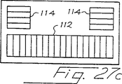
図27は、画像データアレイ112及び単一追跡アレイ114を含む他のトランスジューサ110の概略図を提供する。この場合、追跡アレイ114は、画像データアレイ112に垂直に方向付けられる。図27に示すように、追跡アレイ114は、画像データアレイ112と同じ中心線上に横方向に偏って配置される。
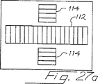
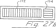
図27aから27eまでは、5個の代替トランスジューサを示し、各トランジューサは1つの単一画像データアレイ112と少なくとも1つの追跡アレイ114とを有する。図27aのトランスジューサは2つの追跡アレイ114を備え、両方のアレイは画像データアレイ112と同じ中心線上に横方向に偏って配置される。図27bのトランスジューサは、画像データアレイ112と同軸線上に軸方向に間隔を保って配置される1つの単一追跡アレイ114を有する。
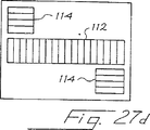
図27cのトランスジューサは、2つの追跡アレイ114を有し、両方とも画像データアレイ112の反対側の端部に接近して画像データアレイ112に対して同じ側に配置される。図27dのトランスジューサは、2つの追跡アレイ114が画像データアレイ112に対して反対側に配置されるということ以外は図27cの場合に類似する。図27eのトランスジューサは4個の追跡アレイ114を有し、そのうちの2個ずつが、画像データアレイ112のそれぞれの側に、画像データアレイ112のそれぞれの端部に近接して配置される。
追跡アレイを画像データアレイの長い方に辺に沿って配置するトランスジューサの幾何図形的配置により、トランスジューサの全長を縮小することが可能であり、用途によっては利点を提供することになる。
図28及び29に示すように、既に説明したように拡張された視界を形成する際の使用に適したトランスジューサ120、120’は画像データアレイ122と追跡アレイ124を利用可能であり、ここに、2つのアレイ122、124のトランスジューサエレメントは相互に平行である。トランスジューサ120において、追跡アレイ124は画像データアレイ122に対して同じ中心線上に横方向に偏って配置される。図29に示すように、トランスジューサ120’において、画像データアレイ122’と追跡アレイ124’は相互に分離されて並列配置される。トランスジューサ120、120’のどちらかを用いる場合、フレーム間の運動は追跡アレイ124、124’を用いて決定可能であり、そして、複合画像は、画像データアレイ122、122’からの画像データによって組み立て可能である。
前述のあらゆる実施例において、追跡アレイ及び画像データアレイの幾つか又は全ては、例えば画線アレイのような、非平面線形アレイとして形成可能である。必要であれば、個別の位置決めされた線形アレイを各音波ライン用として使用することが出来る。
データ追跡用の代替最適化技法
図30は、多くの点で図1のシステム10に類似する代替超音波映像システム10’の構成図である。2つの図面において対応するエレメントには同じ参照番号が用いられており、両者の差に焦点を絞って次の検討を進めることとする。
システム10’は、画像データアレイ18、或いは、追跡アレイ20、22のうちの1つからの画像データを未加工画像データバッファ15内に記憶する。バッファ15内に記憶されるデータは、例えば、I、Qデータ、又は、IFデータであっても差し支えない。勿論、用語「画像情報」は、広範囲に亙って、目標における空間的変化と共に変化する情報を表すことを意図したものであり、多くの場合、画像情報16は決して画像としてディスプレイされることはない。バッファ15内に記憶された未加工画像データには、広帯域超音波パルス動作によって記憶された追跡データが含まれることが好ましい。バッファ15からの画像データは、4つの代替ブロックの1つを介して検波器21にパスされる。ブロック17は、濾波作用を実施せず、一般に、画像データアレイ18からの画像データ用に用いられるオールパスブロックである。追跡アレイ20、22の1つからの追跡データは、フィルタ特性が変化しても差し支えない3つのフィルタ19、19’、19”のうちの1つを通ってパスされる。例えば、フィルタ19はローパスフィルタであり、フィルタ19’はハイパスフィルタであり、フィルタ19”は、周波数スペクトルの任意の所要部分を中心とする帯域フィルタであっても差し支えない。
検波器21は任意の従来型検波器であって差し支えなく、検出済み出力信号をスキャンコンバータ24に供給する。必要に応じて、追跡アレイ20、22からの追跡データは、フィルタ19、19’、19”のなかの異なる幾つかを用いて複数回に亙って処理可能である。勿論、代替実施例においては、これよりも多いか又は少ない個数のフィルタを使用しても差し支えない。
スキャンコンバータ24は、画像追跡データにおけるコントラストを最大化するために公知のヒストグラム等化方法を用いることが好ましい。ヒストグラム等化については、例えばGonzales及びWoods共著「デジタル画像処理」Addison−Wesley、1993年、173−178頁、並びに、Kim米国特許5,492,125において検討されている。スキャンコンバータ24は、画像追跡データを円滑化、或いは、これとは別に処理するために、二次元ローパスフィルタ、及び/又は、二次元ハイパスフィルタを使用することもある。
スキャンコンバータ24からの画像フレームは、フレームバッファ30、32、34に記憶され、バッファ32、34からの画像データの追跡集合は運動推定器38に選択的に供給される。運動推定器38は、選定された画像追跡集合間の相対運動を推定し、これらの運動推定値を運動平滑化/合計ブロック40’に供給する。
運動平滑化/合計ブロック40’は、多数の運動操作からの運動推定を処理する。各運動検出推定は、運動推定と結合した信頼レベルを表す品質係数と結合されることが好ましい。例えば、適当な品質係数は、特定の運動推定値と関連した絶対差の最小の和の値であっても差し支えない。ブロック40’は、重み付けされた和を用いて、多数の運動推定を合成する。例えば、次に示す値および関連品質係数Qを持つ3つの運動値推定値が利用可能であるような状況について考察することとする。
推定値 右へ1−5画素 Q=0.9
推定値 右へ2−3画素 Q=0.8
推定値 左へ3−2画素 Q=0.2
この例において、Qの値が高いことは信頼レベルが高いことと関連している。ブロック40’は、次のように、これらの3つの運動推定値の重み付け和を形成することが出来る。

運動推定の品質を改良するために利用できる他の技法には、最良品質の画像追跡データを獲得するために多重伝達ゾーンを使用する技法、及び、最良品質の画像追跡データを獲得するために、本発明の譲受人に譲渡済みのHossack米国特許5,608,690に示される周波数従属焦点調節を使用する技法が含まれる。
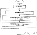
既に指摘されたように、アレイ18を介して画像データを獲得することは、追跡アレイ20、22を介して追跡データを獲得することにより時間分割多重化可能である。一代替実施例において、連続した追跡データフレーム間の時間分離は、所要範囲内に所在する運動推定値を供給するために、適応的に制御される。既に説明したように、連続した追跡フレーム間の運動推定値(即ち変位)が過剰である場合には、当該変位が運動推定器38の測定能力を超過する危険性がある。逆に、連続した追跡フレーム間の運動推定値が低過ぎる場合には、運動推定値を求めるために過度の計算時間が使用される。更に、運動推定値が小さい場合には、相対誤差は大きく、複合誤差は望ましくない割合に到達することがあり得る。これらの問題を回避するためには、既に述べたように、連続した追跡フレーム間で収集された画像データフレームの個数を決定するために、コントローラを装備することが可能であり、これは、図31に示すように、適応的方法において達成される。
図31において、変数Nは、連続した追跡フレームの間で収集される画像データフレームの個数を指定するために用いられる。図31に示すように、Nは、初めに定数K1に設定され、次にコントローラは、図30の運動推定器38からの新規な運動推定値を待つ。この運動推定値が所要範囲以上である場合には、Nは量△だけ減少される。逆に、運動推定値が所要範囲以下である場合には、Nは△だけ増大される。一旦、必要に応じて、Nが改正された場合には、コントローラは、運動推定器38からの新規な運動推定値を待つ。このようにして、運動推定値は所要範囲内に自動的に維持され、そして、過度に大きい運動推定値或いは過度に小さい運動推定値と結合した問題は回避される。
画像転送最適化技法
図30のシステム10’は、リアルタイム或いは遅延後の運動推定を実施するために遠隔コンピュータが用いられる状況における使用に適する。この文脈において、遠隔とは、運動推定コンピュータがケーブル或いは他のデータリンクを介して接続されることを意味するものとする。図30に示すように、バッファ30からの画像データフレームは、遠隔であっても差し支えない現場への転送以前に、例えばJPEGのような任意の適当な圧縮技法を用いて圧縮可能である。遠隔であっても差し支えない現場において画像データが受信されると、ブロック35に示すように、当該データは圧縮解除される。同様の圧縮及び圧縮解除ブロックは、バッファ32、34と運動推定器38の間に挿入することが出来る。例えば、遠隔運動推定及び3Dボリューム復元は、例えば、本発明の譲受人であるAcuson社のAEGISワークステーションのような遠隔ワークステーションにおいて実施可能である。
代替運動推定技法
連続した追跡フレーム間の運動が小さい(1画素1個よりも小さい)状況において、結果的に各追跡フレームが直前の追跡フレームと比較される場合には、運動が間違って推定される危険性がある。例えば、隣接する追跡フレームの間の分離が1つの画素の1/3である場合には、各追跡フレームと直前の追跡フレームとの比較は運動の無いことを検出するはずである。この問題を克服するために、図30の運動推定器32は、図32のアルゴリズムを用いて制御されることが好ましい。このアルゴリズムにおいて、Nは、運動推定に際して基準として用いられる画像領域のフレーム番号を定義し、記号N+1は、基準画像領域と比較されるべき画像領域のフレーム番号数を指示するために用いられる。図32に示すように、第1過程はi=1を設定し、次に、画像領域Nと画像領域N+1との間で運動が検出されたかどうかを決定することである。運動が検出されない場合には、iが増分(インクレメント)され、制御コントロールはブロック130に戻される。一旦運動がブロック130において検出された場合には、基準画像フレームはN+1に等しく更新され、iは1にリセットされ、制御はブロック130に戻される。
一例として、一連の追跡フレーム1、2、3、及び、4について考察することとする。フレーム1と2の間で運動が検出されないものと過程すれば、フレーム3はフレーム1と比較される。フレーム3とフレーム1との間で運動の無いことが検出されたと仮定すれば、同様に、フレーム4はフレーム1と比較される。この過程は、運動が検出されるまで繰り返され、運動が検出された場合に限り基準フレームは新規フレームに更新される。このようにして、サブ画素運動は最終的に検出可能な点になるので、複数のサブ画素運動が見落とされることはない。
基準画像領域の選択は、必ずしも1つのフレーム全体と対応するとはかぎらない。フレーム運動が、当該フレームの最上部においてゼロであり、最下部においてゼロでない場合(扇風機様スイープの場合)には、当該フレームの最上部における運動検出期間中、一方において、旧いフレーム部分は基準として保持され、他方、当該領域において運動が検出されると当該フレームの底部が1度更新されることが好ましい。
追跡アレイ20、22は主として表面に沿ってスイープされるので、主要な運動は、深さ方向でなくて仰角方向において実施される。絶対差の最小和(MSAD)の探索に際して、探索領域は方形であるよりは矩形であることが好ましい。例えば、64x64画素面積を探索する代りに、128x32画素面積(横方向探索128画素と深さ方向探索32画素)を同じ時間内に探索することが出来る。同様に、最大運動が64画素である場合には、探索面積を32x64画素に制限することにより、探索時間が大幅に短縮される。
更に、処理時間を更に短縮するために、フレーム運動を補間することが出来る。
例えば、運動検出のために追跡フレーム(1、2、3、4、及び、5でなくて)1、3、及び、5が使用される場合には、フレーム2に関する運動を決定するために、フレーム1と3の間の検出済み運動を補間することが出来る。この場合、フレーム2に関して補間された運動は、フレーム1と3の間の検出済み運動の半分であるはずである。この方法は、運動検出のために費やされる処理時間を短縮することを可能にし、しかも、獲得した全ての画像データを最高品質3D画像に使用することを可能にする。このタイプの補間は、図30の3Dボリューム変換補間ブロック38において実施可能である。
処理時間を更に短縮するために、運動推定器38において種々の代替方法を使用することができる。例えば、音波ラインの小さい集合が、一次元のRF又はベースバンド信号として送信され、受信され、そして、記憶される場合、これらのラインの各々に沿った運動のベクトル成分は、当該ラインに沿った一連の連続サンプルを相関させることによって推定することが出来る。このように、各々のライン方向における運動ベクトル成分が決定可能であり、そして、最終的な二次元運動推定を作成するために、これらの運動ベクトルを合計することが出来る。必要に応じて、当該集合内の2つよりも多い音波ラインを使用することも出来るが、次に示す例においては、2つの垂直音波ラインが用いられる。
例えば、図33に示すように、相互に垂直な2つの音波受信ライン140、142を記憶するために追跡アレイ20を使用できる。これらラインは、追跡データで構成される1つの単一フレームを作るものとみなすことが出来る。矢印144の方向に沿った運動ベクトル成分を見付けるために、追跡データで構成される2つの個別フレームの間でライン140を相互関連付けることが可能であり、同様に、矢印146の方向における運動ベクトル成分を決定するために、追跡データで構成されるこれら2つのフレーム内の線142を使用することが出来る。次に、追跡データで構成される2つのフレーム間の二次元運動を推定するために、これら2つの運動成分をベクトルとして合計することが出来る。現行課題への適用に適した交差相関技法については、Engeler米国特許4,937,775、O’Donnell米国特許4,989,143、及び、Wright等の米国特許5,570,891に記述されている。Wright等の特許は、本発明の譲受人に譲渡済みである。
2つの方向のうちの一方における放射から標本採取した複雑なビームデータを記憶するためにレジスタを使用することが好ましい。一瞬遅れて同じビームが再度形成される場合には、結果として標本採取されるビームデータは当該レジスタ内のデータと交差関連付けられる。2つの信号の間の相対的遅延時間は交差相関ピークの位置から決定される。交差相関過程は利用可能なラインデータの1つ又は複数の部分に作用する。各線に沿った多数の点における交差相関を介して運動を検出することにより、当該画像の最上部および最下部における個別の運動が決定され、従って、変換並びに回転が推定される。測定を遅延させるために必要なトランスジューサの運動成分(ビーム軸に平行)は、交差相関ピークによって決定される遅延時間から、組織内における既知音速と遅延が2方向通路長に関係するという事実に基づいて推論される。この過程は、もう一方の運動ベクトル成分を見付けるために、もう一方の線(第1の線に垂直に位置決めされることが好ましい)に関して繰り返される。次に、当該アレイに沿った所定の点において推定された実際のトランスジューサ運動を見つけるために、これら2つのベクトル成分が合計される。同様に、この過程は、当該アレイの第2の側において第2の追跡アレイに関して繰り返される。
一実施例において、2つの線(従って2つのビーム)は、±45度の角度で位置決めされる。従って、格子ローブを回避しようとする場合には、エレメントの間隔に関して厳しい必要条件が適用される。他の実施例において、2つの線は、患者の皮膚に沿った運動検出の精度を上げるために、±60度の角度に位置決めされる。トランスジューサエレメントの間隔は半波長以下であることが好ましい。この必要条件は、画像データアレイ用としてでなく追跡アレイ用として一層低い周波数の使用を推奨することになる。ただし、交差相関技法は、波長に比較して非常に小さい長さに相当する遅延を追跡することを可能にする。前の場合と同様に、1組の追跡データとその次の組の間の比較は、獲得された全ての追跡データ集合について実施されることなく、時間間隔を持つ部分集合に関して実施される。
例えば、運動が速い場合には、追跡データ集合の連続した全ての対データ間において運動推定が実施可能であるが、運動が遅い場合には、運動推定の間の時間を更に長くすることが許容される。
高速運動検出探索技法
推定運動に関する探索速度を上げるために様々な方法が利用可能である。これらの方法は、既に説明した任意の実施例と共に使用できる。
1.システムコントローラ又はユーザ入力のいずれかは探索されるべきブロックサイズを変更することがある。大きいブロックサイズは、より多くの計算を必要とするが、或る特定の画像タイプ(例えばノイズデータ)に関しては、大きいブロックは一層品質の高い結果を与える(即ち、下位最小SAD対平均SAD)。
2.システムは、前の運動推定に基づき探索面積を適応的に変更する。最後の運動が右に10画素であった場合には、右に0画素から右に20画素までの面積に亙って探索可能である(即ち、探索面積の中心は前の運動測定による指示によって予測される運動の中心に置かれる)。
3.検出された運動が殆ど変化を示さない場合には(例えば、連続運動測定において、5、15、8、12画素と反対に右へ7、8、10、9画素)、運動が7と10との間に在ることは比較的信頼度が高いので、システムは更に小さい探索面積を使用しても差し支えない。逆に、連続運動の推定値が広範囲に亙って変化する場合には、探索が成功すること(即ち、運動は探索面積の限界を越えない)を最大限に保証するために、システムは更に大きい探索面積を使用する傾向がある。前述の例において、画素運動が7、8、10、9である場合には、15x15探索面積が用いられるが、画素運動が5、15、8、12である場合には、30x30探索面積が用いられる。
4.大抵の運動は、レンジ方向でなくて横方向において予測されるので(トランスジューサは皮膚の表面を横断して動かされる)、例えば、レンジ方向に+/−5画素、横方向に+/−20画素のように、探索面積は非対称であり得る。
5.探索は、複数レベルの空間解像度において実施可能である。最初は、例えば画素位置3つ目毎のテストのように、探索は横方向にのみ粗く実施される。このようにして、一旦、概略横方向の偏りが検出されると、微細な探索(全ての画素位置)が横方向及びレンジ方向の両方に行われる。
6.階級的運動検出は、複数の信号水準解像度レベルに基づいて使用可能である。最初は、最小SAD位置を見付けるために、各画素の強度レベルに関連した最上位の2または4ビットのみが用いられる。一旦、所要位置が概略発見されると、第2水準の探索が、全てのビット、一般には8ビットを用いて当該領域において実施される。2つ以上のレベルの階層を使用することが出来る。
更に解像度の高い追跡技法
利用可能な画素の間に追加画素を補間することにより、最も微細水準の運動検出を強化することが出来る。Li及びGonzalesによって「ビデオ技術用回路及びシステム」に関するIEEE議事録、6、1、頁118(1996年2月)に発表された代替方法においては、最小SADに対する近傍SAD値の値に基づくサブ画素解像度に関して運動推定値を計算する。
運動推定を結合するための技法
トランスジューサ運動の最終推定は、多重入力の合成値に基づくことが好ましい。最高品質(或いは確実性)を有すると推測される入力が最も大きく重み付けされるように、これらの入力が重み付けされることが好ましい。大多数の入力と矛盾している入力は、合成計算から除外されるか、或いは、非常に小さく重み付けされる。
先ず、絶対差の平均和(「mean_SAD」)に対する絶対差の最小和(「min_SAD」)の比率が、品質係数として用いられる。この比率が低い場合は結果が高品質であることを示し、結果が1.0に近い場合には信頼度の低い推定であることを示す。実際上、良好な比率が0.3未満であることは稀である。比率が0.3から1.0までの範囲内に在ると仮定すれば、この比率は、0.0から1.0までの範囲内の重み付け関数に変換することが出来る。
ここに1.0は理想的な(高い確実性の)結果を意味し、0.0は使用できない結果を意味する。
Weighting_MSAD=(1−(min_SAD/mean_SAD))/0.7
最小観察可能SADが<0.3である場合には、この方程式は次のように修正可能である。
Weighting_MSAD=(1−(min_SAD/mean_SAD))/(1−min_observable_SAD)
第2の品質係数は、その前の推定値に対する現行運動推定の類似性に基づく。この方法は、実際上一般的に使用される平滑走査に際して、1組の追跡データとこれに続く1組の追跡データとの間の実際の相対運動は類似するという観測結果に基づく。運動推定によって逆運動が予測された場合には、それが不良推定である可能性が高い。不良推定の原因には、ノイズ画像、貧弱な画素コントラスト、または、大量の流血の存在が含まれる。基準として用いられるその前の運動推定が、MSAD動作からの未加工運動推定、或いは、その前の平滑化および重み付け済み推定のいずれかである可能性のあることに注意されたい。これに対して最も最近の未加工推定が比較される基準として、平滑化された前の運動推定が用いられることが好ましい。
現行例において、運動推定間の類似性の程度は次のように算定される。この例は、Y(仰角)方向運動に関するが、Z(深さ)方向運動にも適用可能である。Weighting_seqは、順次推定の比較に基づいて生成される重み付け係数である。
Weighting_seq=1−[abs(Ycurr−Ylast)/(abs(Ycur)+abs(Ylast))]
ここに、Ycurr=平滑化されたY運動の最終推定。
初期運動計算に関しては、前の値推に対する類似性の測定が不可能であるので、初期運動に関係した重み付けば、例えば0.5のような任意の値を用いなければならない。
次に、合成重み付け係数(「Weighting_comp」)が形成される。
実際の組織走査による経験から、MSAD品質または順次的品質のどちらに偏った重み付けを行うかを選択することが出来る。現在では、全重み付けの0.75はMSAD品質に、0.25は順次的品質に関係付けられる。
Weighting_comp=0.75xWeighting_MSAD+0.25xWeighting_seq
これらの重み付けば、運動推定の対象とされた全ての点に関して算定される。一例において、6件の運動推定がレンジ方向に実施された。各々の場合に、48x48画素ブロックが用いられた。
実際の運動に関しては、運動を深さの関数として表す方程式は直線に従わなければならないので、求められた運動推定を直線に適合させることが出来る。重み付けされた最小二乗法を用いて運動を適合させることが好ましい。ここに、重み付けは、その点に関して運動が入手可能な各々のレンジポイントに関して上述した通りである。この過程は、Y方向運動及びZ方向運動の両方に関して繰り返される。
最終的に、適合済みの運動を決定することにより、切片(c)と勾配(m)によって定義される直線が得られる:Y_motion=mZ+c。
同様に、Z観測点の関数としてのZ運動が算定される。
Z_motion=mZ+C(異なるmとc)
一般に、Z_motionはZの関数としての定数であることが期待されるが、方位軸のまわりのトランスジューサの回転の場合には適用されない。
この適合値は、パラメータWeighting_compの平均に基づいて更に円滑化される。従って、非常に低品質の推定が存在する場合には、現行の推定は主として前の推定(現行推定でない)に基づく。
m_mod=fact*(mean(Weighting_comp))*m+(1−fact*(mean(Weighting_comp))*m_last
c_mod=fact*(mean(Weighting_comp))*c+(1−fact*(mean(Weighting_comp))*c_last
c 切片の現行推定値
c_last 前のフレーム対運動推定からの切片
c_mod 修正済み切片
m 勾配の現行推定値
m_last 前のフレーム対運動推定からの勾配
m_mod 修正済み勾配
fact 重み付けにどの程度の重要度を付加するかを決定する係数(現行fact=1.0)
その代りに、最終Weighting_compはファジー理論を用いて決定しても差し支えない。ファジー理論制御ブロックは入力としてWeighting_MSAD、及び、Weighting_seqを用い、Weighing_compである出力を形成するために、これらを結合する。入力Weighting_MSAD、及び、Weighting_seqは、先ず、クラスに割り当てられる(Weighting_MSAD、及び、Weighting_seq用にクラスを分ける)。これらのクラスは、「低」、「中」、「高」である。メンバーシップ(帰属関係)は、図34に示すような3つの三角様領域のいずれに入力が該当するかに基づく。特定の測定値がどのクラスに所属するかを定義する線(ライン)の位置の導出は実験に基づく。領域は、三角形として図示されるが、良好な結果を与えることが実験的に決定される任意の連続関数に従うように整形されても差し支えないことに注意されたい。クラス関数の水平軸は入力値(Weighting_MSAD、または、Weighting_seq)に対応し、垂直軸はクラスのメンバーシップ(帰属)の度数を定義する。この場合、同じクラスのメンバーシップダイアグラムがWeighting_MSAD、及び、Weighting_seqの両方に関して使用される。メンバーシップダイアグラムにおける類似したクラスは、図35に示すように、ファジー出力Weighting_compに関して導出される。この場合、ダイアグラムには5つの領域が有る、即ち、極低、低、中、高、及び、極高である。
Weighting_compを決定するためには次のファジー則が適用される。これらの規則において、Weighting_MSADとWeighting_seqとの間には論理ANDが成立する。
0.35入力の結果は「低」クラスメンバーシップの0.5度であり、「中」クラスメンバーシップの0.5度である。0.9入力の結果は「高」クラスメンバーシップの1.0度である。
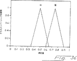
従って、規則3及び6は真であるが、出力Weighting_compに関しては異なる値を提供する(それぞれ、「中」及び「高」である)。これらの規則に関して可能な出力を図36に示す。
先ず、規則3において、Weighting_MSADの低値は論理ANDを用いてWeighting_seqの高値と結合され、2つの式の最小値が規則3の真理水準として用いられる。Weighting_MSADに関する「低」メンバーシップが0.5度であることは、Weighting_seqに関するクラス「高」メンバーシップが1.0度未満であることである。従って、規則3の真理水準は0.5である。
規則6の場合には、Weighting_MSADの「中」値は、論理ANDにより、Weighting_seqの「高」値と結合され、2つの式の最小値が規則6の真実水準として用いられる。Weighting_MSADに関する「中」メンバーシップが0.5度であることは、Weighting_seqに関するクラス「高」メンバーシップが1.0度未満であることである。従って、規則6の真理水準は0.5である。
図36におけるWeighting_comp関数メンバーシップに関する「中」及び「高」ラベルは、上記のファジー規則によって定義される真理水準において先端が切断される。これを図37に示す。
Weighting_compに関する数値出力は、図心ファジー化解除技法を用いて導出される。図37に示す全斜線領域の重心の推定が行われる。この場合、重心は0.625に在り、従って、出力Weighting_compにはこの値が割り当てられる。
Weighting_compが決定されると、重み付けされた最小二乗適合値を決定し、そして、現行運動が現行推定またはその前の運動推定にどの程度まで基づくべきかを決定するために上記の方法を使用できる。
勿論、以上の検討から、X、Y、かつ/または、Z方向において検出された運動は局部運動、即ち、当該トランスジューサ及びそのアレイの現行位置及び方位に関する運動であることは明白である。最初、走査開始に際して、局部的なX、Y、及び、Z方向は、当該トランスジューサの運動期間を通じて一定状態を維持する仮想大局軸系に対応するものと一般的に仮定される。扇風機様スイープに際して、当該トランスジューサが画像平面の方位軸のまわりに回転する場合には、局部的Z運動(トランスジューサの深さ方向)は、大局Yまたは仰角方向における有意成分を含むまで回転を継続するはずである。当該トランスジューサの検出された全ての運動に関して、大局軸系における当該トランスジューサの新規な位置及び方位が算定される。大局軸系に関する局部的なX、Y、及び、Z方向の位置付け(オリエンテーション)(即ち、当該トランスジューサの方位角、仰角、及び、レンジ、または、深さ)が更新される。従って、トランスジューサの局部的なZ方向における運動のその次の解析は、例えば、大局的なZ及びY方向における成分に分解される。
一例として、トランスジューサの深さ又はZ方向が、最初に大局Z方向と直線配列されるように下方を指した状態から、大局Z方向に関して45度の角度を作るまで回転した状態について考察することとする。10個の画素で構成されるトランスジューサの局部的なZ方向における運動は、この段階において、大局Y方向における10cos(45°)に大局Z方向における10cos(45°)を加算した成分に分解される。この例において、局部的Z方向は、依然として大局的X方向に関して垂直に位置決めされたままであり、従って、局部的Z運動は、大局的X方向には成分を持たない。
一般に、大局的軸方向に関する局部的軸方向の関係は余弦(コサイン)を用いて算定され、算定結果は、当該トランスジューサが当該ボリュームに亙ってスイープされるにつれて連続的に更新される。好んで、これらの方向余弦は3つの軸全てに関して連続的に維持される。
ここで用いられる場合には、用語「運動成分」は、平行移動成分、回転成分、及び、その組合わせを広く包括することを意図するものである。
データ重複技法
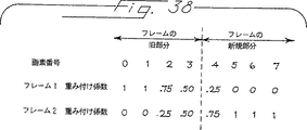
既に説明したように、拡張視界を得るために画像データの2つの領域が結合された場合、異なる画像データフレームからのデータの境界において、滑らかな補間方式を使用することが好ましい。図38に示すように、この種の滑らかな補間方式を提供するために、可変重み付け係数を使用することが出来る。図38において、直ぐ前のフレームの右縁は画素3で終了し、当該フレームの新規な画素4で始まる。前のフレーム1のために用いられる重み付け係数は、旧フレーム内の画素0及び1における1から当該フレームの新規部分内の画素5、6、及び、7における0まで滑らかに降下する。逆に、その次のフレーム2用の重み付け係数は、旧フレーム内の画素0及び1における0から、当該フレームの新規部分の画素5、6、及び、7に対する1まで徐々に上昇する。一般的に、上記の任意の実施例において、画像におけるノイズを軽減するために、蓄積された画像データに関して組み合わせ操作を用いることが出来る。同様に、組合わされたデータは、ノイズを軽減するために、追跡データと共に使用可能である。
運動成分の不正確な推定を検出するための技法
画像アレイ平面および画像アレイ上の画素に関する三次元画素位置の定義を作成するために、追跡アレイから放射されるビーム線(ライン)に沿った運動推定値を用いる様々な方法がある。
11つの方法は、最小二乗又は重み付けされた最小二乗法を用いて直線を適合させる方法であり、この場合、運動の品質は重み付け係数として用いられる。これらの線に基づき、それらが関連した三次元運動と共に、多数の点を識別することが出来る。例えば、当該領域の最上部左、最下部左、最下部右、及び、最上部右部分に4個の点を選定することが可能であり、画素位置を見付けるために2線補間法を使用することが出来る。線に沿った運動推定から、平面(Y=a+bX+Cz)に関する方程式が適合可能である。適合の品質は、最小二乗又は重み付けされた最小二乗技法によって測定可能である。次に、以前に識別済みの重要な4点を用いて、平面に関する方程式を見つける。即ち、例えば行列反転(マトリックスインバージョン)技法を用いてa、b、cを見付けるために、3点に関する3方程式Y=a+bX+cZを適合する。この過程は、重要な4点のうちの3点で構成される異なる1組に関して繰り返される。比率a1/a2(ここに、a1及びa2は3点で構成される異なる組から導出された「a」値である)、b1/b2、または、c1/c2がスレショルドを越えた(大き過ぎるか、或いは、小さ過ぎる)場合には、当該システムは、平面が傾斜していること、及び、再走査が適切であることをビデオ出力を介してユーザに警告するようにプログラムすることが可能である。
線及び平面のどちらか又は両方の場合において、二乗誤差の和は、低品質運動推定の測定手段として使用し、そして、運動推定を内部的に適応するか(即ち、更に大きいブロックサイズを使用するか、或いは、さらに多くの運動推定を実施する)或いは、例えば再走査を促すためのビデオ又は可聴警告としてユーザに供給するために使用することが出来る。同様に、連続する運動推定値の間で検出された運動エラー誤差を累積し、そして、プリセットされたスレショルドに対して累積的な運動誤差を比較することが可能である。累積運動誤差がこのスレショルドを横切る場合には、当該システムは、累積的な位置誤差が不満足であること、そして、再走査が好ましいことをユーザに警告するようにプログラムされることが好ましい。累積運動誤差(二乗誤差の和から導出可能であるが、必ずしも正確に二乗誤差の和に等しいとは限らない)は、随意選択可能に、ユーザに対してディスプレイ可能である。
代替3D表示技法
既に述べたように、多重2Dスライスは、ソリッド3Dボリューム集合に復元可能である。勿論、これが、出力ディスプレイ46を形成するために使用出来る唯一の方法ではない。例えば、更に簡単なディスプレイには、2D投射としてディスプレイされるが、3D形式であるディスプレイ用基準制約ボックスが含まれる。画像データの全ての平面の位置及び角度オリエンテーションは、既に述べた運動検出情報を使用して、以前と同様に算定される。ただし、この代替方法において、選定済み2Dスライスは、スクリーン上にディスプレイされた3D制約ボックス内に適応された状態で、ディスプレイされる。これは、Keller米国特許No5,353,354に記述されている過程を用いて実施可能である。二次元スクリーン上に三次元として規定される画像データを投射するための技法は公知であり、例えば、「コンピュータグラフィックス」(Foley等、Addison−Wesley、1995年)の章5及び6に記載済みである。勿論、3Dフレーム内での1つの単一2Dスライスのディスプレイは、既に述べた一般的な3D復元及び視覚化システムの部分集合である。
代替ビーム形成技法
上述の実施例は、ディスプレイ用データを収集するために画像データフレームを、そして、トランスジューサの相対運動を決定するためのデータを収集するために追跡フレームを使用する。画像データフレーム及び追跡フレームのためのアパーチャは物理的に分離されているので、画像データのこれらのフレームの収集は、実際には、2つの独立したビーム形成器タスクを形成する。ビームの多重同時送信、及び/又は、受信は、必要に応じて、追跡データの累積に必要な時間を節減するために使用できる。画像データフレーム及び追跡フレーム用超音波ビームを同時送信するために容易に適応可能な多重送信ビームシステムの一例は本発明の譲受人に既に譲渡済みの米国特許出願第08/673,410号に開示されている。同様に、多重受信ビームビーム形成器は、各送信ビームに関して個別の受信ビームを提供し、それによって、データ収集速度を上げるために使用することができる。本発明の譲受人に譲渡済みの米国特許出願第08/432,615号に開示されている多重受信ビームビーム形成器はこの目的用に適応可能である。O’Donnell米国特許4,886,069に開示されている多重受信ビームビーム形成器も参照のこと。
米国特許出願08/419,595、及び、08/418,640に開示されているコヒーレント画像形成技法であるWright等による「コヒーレント画像形成のための方法及びその装置」(本発明の譲受人に譲渡済み)は、本発明の選定済み実施例と共に有利に使用出来る。Wright特許出願のシステムは、近傍場(フィールド)における隣接走査線間の位相調を提供し、それによって、シフト不変スペックルパターンを提供する。この種のシフト不変スペックルパターンは、小斑点(スペックル)追跡に基づき、走査線間の位相調整欠如に起因してスペックルパターンがシフト変化する従来型システムを用いて達成可能な場合よりも優れた画像運動検出を提供するはずである。
代替オペレータ警告メッセージ
追跡アレイの一方が運動を検出し、他方が検出しない場合には、この状態は、運動の無いことを示す方の追跡アレイが組織に接触していないことの表示であると推測することが出来る。システムコントローラは、例えば可聴音またはディスプレイスクリーン上の視覚的メッセージのような警報メッセージを用いてシステムオペレータに警告することによって、この状態に応答するプログラムされたロジックを含むことが好ましい。
結論
既に述べたシステム及び方法は多数の重要な利点を提供する。これらは、磁気的位置決め(オリエンテーション)法と対照的に、電磁的環境および患者の運動には感応しない。本発明は、磁気的方法よりも低コストで実現可能であるものと推測され、しかも、更に低位の仕様のトランスジューサアレイを用いることが出来る。周波数に比例する映像解像度によって精度が決定されるので、既に述べた技法は、優れた精度の見当合わせ(レジストレーション)を提供する。
既に述べた改良されたトランスジューサは、用途に応じて、更に多量または更に大きいケーブルを必要とし、トランスジューサのフットプリントが僅かに広がる可能性がある。ただし、これらの潜在的な問題は、以上に述べた技法を用いて最小限に抑制することが可能なはずである。
勿論、以上の詳細な説明は、制限的意味を持つものでなく、現時点における本発明の好ましい形式を例証するものと見なされるべきである。次に示す請求の範囲は、全ての等価事象を含み、本発明を定義することを意図するものである。Cross-reference with related applications
This application was filed on February 29, 1996, and is a continuation-in-part of March 25, 1996, which is a continuation-in-part of provisional US Patent Application No. 60 / 012,578, assigned to the assignee of the present invention. This is a continuation-in-part of copending US patent application Ser. No. 08 / 821,581.
Background of the Invention
The present invention relates to an improved system, method, and transducer for obtaining two-dimensional image information and relative positional information about the image information to enable subsequent three-dimensional or extended field of view reconstruction.
Interest in 3D ultrasound images is increasing. One method is to use a two-dimensional transducer array to obtain 3D image information directly. The two-dimensional array can be scanned electronically at any required determined location, thereby obtaining the required information. This method involves significant problems associated with manufacturing difficulties, signal-to-noise difficulties, and processing difficulties.
Another method uses a one-dimensional transducer array with relative position information between image data frames so that these frames can later be assembled into a three-dimensional volume to form the required three-dimensional reconstruction. Collecting multiple two-dimensional image data frames. One method is to use a motorized array to collect the required set of image data frames by precisely controlling the motion of the transducer array. One example is US patent application Ser. No. 08 / 267,318 (Hossack). etc , Already assigned to the assignee of the present invention). (See also Pini US Pat. No. 5,159,931). A related method is described by McCann et al., “Multidimensional Ultrasound Imaging for Cardiology” (IEEE Bulletin, 76 9, pages 1083-1072 (September 1988), using a large rotary transducer. Another method is to use manual motion detection techniques based on the analysis of ultrasound images. Sapoznikov et al., “Left Ventricular Shape, Wall Thickness, and Function Based on Three-Dimensional Reconstructed Cardiac Records” (“Computer in Cardiology” IEEE Computer Society Newspaper, Cat CH 2476-0, pages 495-498 1987) and “3D reconstruction of echocardiogram based on orthogonal section” by Taruma et al. (“Pattern recognition”, 18 2, pages 115-124, 1965). Manual techniques are slow and cumbersome and have many disadvantages.
Schwartz US Pat. No. 5,474,073 describes a qualitative three-dimensional method using a hand-held transducer array and virtual scanning motion. Since qualitative methods have drawbacks, the present invention is directed to quantitative methods.
Keller US Pat. No. 5,353,354 discloses a transducer array with a magnetic sensor designed to measure the accelerometer or transducer's determined position, and thus the relative motion between the respective image planes. To do. Once the positional information of the image plane is provided, a standard method for assembling the image plane information into a three-dimensional volume and providing a suitable display such as cross-section, surface rendering, segmentation, etc. Is used. One drawback of the Keller method is that it relies on evaluating the position of the transducer array relative to a fixed surface external to the patient, not to the patient or other target. If the patient moves, the absolute positions of all target regions are moved and the accuracy of the three-dimensional reconstruction is reduced or completely ignored. Magnetic sensor systems have additional disadvantages such as potential vulnerability to local magnetic interference from, for example, metal objects and electromagnetic fields generated by electronic equipment such as cathode ray tubes. The accelerometer system relies on two stages of integration to convert acceleration information into displacement information, so it is often bulky and susceptible to cumulative errors.
The present invention is directed to novel systems and transducers that overcome the above problems over a wide range.
Summary of invention
A method is provided for registering image information obtained from a target in accordance with a first aspect of the present invention. In this method,
(A) obtaining a plurality of sets of image information using at least one ultrasonic transducer array, wherein the at least one array is moved between at least some of the image information, the plurality of sets being a plurality; Image data sets and multiple tracking sets,
(B) automatically determining a component of motion based on a comparison of at least one portion of the tracking set obtained in step (a);
(C) automatically using the motion components determined in step (b) to register selected some of the image data sets acquired in step (a).
In accordance with one aspect of the present invention, image data set collections are acquired using different transducer arrays. In accordance with another aspect of the invention, motion estimation is used to create an expanded view, in which case no separate array is required for the tracking set.
The present invention is further directed to an improved transducer suitable for use in the method described below. The transducer of the present invention includes a support element and first, second, and third transducer arrays coupled to move with the support element. The first transducer array is arranged along an azimuth axis and has a first and second ends spaced along the azimuth axis and a first central image plane. Has a transducer element. The second transducer array has a second transducer element disposed near the first end of the first transducer array and a second central image plane. The third transducer array has a third transducer element disposed near the second end of the first transducer array and a third central image plane. The first and second central image planes are not parallel, as are the first and third central image planes.
This arrangement for an ultrasonic transducer allows both tracking information and image information to be collected simultaneously. Tracking information is used to determine an estimate of the target motion between the transducer and / or each image data frame. This information can then be used in registering each image data frame to be suitable for three dimensions to form the required three-dimensional representation.
In connection with the preferred embodiment, further aspects and advantages of the present invention will be discussed below.
[Brief description of the drawings]
FIG. 1 is a block diagram of an ultrasound imaging system incorporating a presently preferred embodiment of the present invention.
FIG. 2 is a schematic perspective view of the transducer of FIG.
3 is a schematic side view of the transducer of FIG.
4 is a schematic plan view of the transducer of FIG.
FIG. 5 is a schematic diagram of a portion of the system of FIG.
FIG. 6 is a schematic perspective view showing the motion of the image area when the transducer of FIG. 2 is rotated about the azimuth axis.
7, 8, 9, and 10 are schematic diagrams showing images acquired using the transducer of FIG. 6 at the four rotational positions of the transducer.
FIG. 11 is a schematic perspective view showing the operation of the transducer of FIG.
12 is a schematic plan view of a tracking image region generated by the system of FIG.
FIG. 13 is a schematic diagram illustrating averaging of motion estimates in the system of FIG.
FIG. 14 is a schematic diagram showing how the overall motion of the imaged organ is recognized and ignored in the system of FIG.
FIG. 15 is a schematic diagram illustrating target motion between acoustic lines when the transducer of FIG. 2 is rotated about an azimuth axis.
FIG. 16 is another sketch of the raw acoustic wave line data of FIG.
17, 18 and 19 are three schematic perspective views showing how multiple image data frames are registered with each other in three dimensions to form a three-dimensional representation.
FIG. 20 is a sketch of a display generated by the system of FIG.
FIG. 21 is a schematic diagram of a modified model of the transducer of FIG.
FIG. 22 is a schematic diagram of an alternative ultrasound imaging system.
FIGS. 23 through 26 are plan views of a transducer using a cross array suitable for use in selected embodiments of the present invention.
FIGS. 27 and 27a through 27e are plan views of alternative transducers suitable for use in selected embodiments of the present invention.
Figures 28 and 29 are plan views of alternative transducers suitable for use in selected embodiments of the present invention.
FIG. 30 is a block diagram of an ultrasound imaging system incorporating a preferred embodiment of the present invention.
31 and 32 are flowcharts of regular processes performed by the video system of FIG.
FIG. 33 is a schematic diagram illustrating the operation of an alternative embodiment.
Figures 34 through 37 are graphs illustrating the operation of a fuzzy logic system included in an alternative form of the present invention.
FIG. 38 is a diagram illustrating a method of weighting two frames to form an extended field of view.
39 and 40 are schematic diagrams for one single block motion estimation system.
Detailed description of the presently preferred embodiment
Referring to the drawings, FIG. 1 is a block diagram of an
System overview
The
The
The beamformer system /
Further, the scan-converted image information from the
The frame of image data in the
Image information from tracking array
In
In one mode of operation, rotating the
FIGS. 2-4 show three views relating to the
The
To obtain an image plane as shown in FIG. 2, the transducer geometry shown in FIGS. 3 and 4 can be used. The
For simplicity, the tracking
By making the tracking array pitch an integer multiple of the image data array pitch, the same beamforming delay can be used, but it is necessary to disconnect the appropriate channels as shown in FIG. In FIG. 5, the inter-element pitch of the
A common signal conductor can be used between the beamformer /
FIGS. 6 through 11 are schematic diagrams illustrating a method of using the images generated by the tracking
In contrast, the image planes 60A, 60B, 60C and 62A, 62B, 62C for each tracking
7 to 10 show four sets of images. Each set includes
If the image plane of the
An important advantage of the
Beamformer system /
As the
In some applications, the
In order to reduce the interference between the
Crosstalk can be further mitigated by frequency coding and voltage level techniques. The tracking
The voltage level may not be the same between the two sets of
FIG. 22 shows an
If
Motion detection can be performed manually, for example by drawing a line on the display data of a particular recognizable feature in the
A better method is to use computer analysis of interframe motion using cross-correlation or similar methods on the image data obtained by the tracking
Described by Bohs and Trahey, “A Novel Method for Ultrasound Imaging Independent of Blood Flow and Tissue Motion Angle” (IEEE Proceedings, Biomed. Eng. 38, IEEE pages 280-286, March 1991) Any suitable correlation technique can be used, including computed cross-correlation and absolute difference summation. Cross-correlation is a well-known mathematical operation that uses a sum of multiplications sequentially obtained for various transformations of search data relating to transformations that best match two sets of data. The absolute difference sum method is a simpler correlation technique that is computationally simple, but has substantially the same effect. Data sets are converted by non-constant quantities. For each transformation, the respective data values in each set are subtracted and the sum of absolute differences is calculated. If a particular transformation yields a sum of absolute differences close to zero, it is likely that the data set has been adjusted by the associated transformation. The transformation required to achieve the adjustment is a representation of the motion between each two frames on the side of the image closest to the respective tracking array. As described below, motion in other portions of the image can be evaluated using motion detected in both tracking array and linear interpolation techniques along the orientation of the
The size of the data block used in both types of correlation is a problem with optimization. Larger blocks reduce the likelihood of incorrect matching, but require longer computation time. The maximum detectable interframe displacement is limited by the block size. In general, the search is performed up to plus and minus amounts corresponding to half the block size. As an example, a 16 × 16 pixel block can be used to detect a maximum conversion of + −8 pixels.
The tracking image data used for motion estimation can use any one of a number of forms including at least the following items.
1. Adjacent pixels in the output display (interpolated from actual sonic line data).
2. A pixel selected from a larger grid, eg every Nth pixel.
3. The average value of a group of pixels, for example the average of a group of four adjacent pixels.
4). Sample from prescan converted beamformer acoustic line data.
The beamformer output line of the sonic data may be in polar format or Cartesian format. Since the relationship between these data lines and the physical line of propagation is known, samples derived from these acoustic lines can be used for motion detection.
FIG. 15 is a schematic diagram showing target positions in frames N and N + 1 with respect to the sonic scan line data. The
The “+” symbol in FIGS. 15 and 16 is used for the target position for both N and N + 1 frames. When
When acoustic line data is used in a motion estimator, it can correspond to digitized RF, digitized IF, digitized baseband, or rectified and low-pass filtered envelope detected signals. As an example of the envelope-detected signal, B-mode data can be used. The sound wave line data signal is assumed to be a real digital sample or a complex (I, Q) data sample.
In the presently preferred embodiment, the method used in
For example, the
Accordingly, the motion of the image planes 60, 62 relative to the centerline can be used to determine the relative motion of the
Strictly speaking, only two motion detection operations are required per tracking array. However, the accuracy of the method can be further increased by performing multiple tracking operations over various parts of the image (not necessarily on the centerline). For example, as shown in FIG. 13, a smooth straight line drawn so as to fit can be used to obtain an average value of a large number of estimated values of the motion component to be detected. In FIG. 13, an arrow by a broken line represents an adapted motion component, and an arrow by a solid line represents an actually measured motion component. By obtaining an average value of a large number of measured values, an estimated value with higher reliability can be obtained. This average value can be used for both the amplitude and angle of the motion component vector.
Furthermore, motion estimates that are fundamentally different from neighborhood estimates can be discarded as inaccurate. As shown in FIG. 14, the image of one of the tracking arrays includes an
Furthermore, in the absolute difference sum calculation, the ratio of the minimum sum to the average sum (after removing the value of the minimum sum) can be used as an indicator of image motion detection quality. If the minimum sum is close to average, the calculation is susceptible to errors, i.e. erroneously detected motion. When an LSI 64720 integrated circuit is used, the sum output of error values is a low quality result indicator (a large sum of error values corresponds to a low quality result).
Poor tracking quality can also be detected by comparing motion estimates. The fact that adjacent or continuous estimates of motion are not similar to each other may indicate a low quality of motion estimation. Of course, two or more of the above methods may be used in combination.
The speckle pattern changes rapidly when exercise occurs. In particular, when the elevation slice position moves, the speckle pattern changes. The reason is that the speckled scatterer moves in and out of the image plane without remaining in the image plane and moving parallel to the image plane. Accordingly, in many cases, it is preferable to frequently determine motion estimates as the
As an example, 30 image data frames from the
When implemented based on a small sum of motion detection values, motion detection often works best, but it may be important to use motion detection between frames N and NM. Here, M is an integer greater than 1, such as 10, for example. In principle, this method can be used to correct cumulative errors. However, the probability that this type of large motion is correctly estimated is small. Therefore, the value of M is a problem related to optimization.
Since elevation slices affect the quality and stability of the speckles, it is preferable to track motion at the elevation focus of the lens. Instead, if the speckle dependence is too sensitive at elevation focus, it is preferable to avoid that part. In smoothing operations to maximize net accuracy by targeting more accurate data, it is preferable to apply varying weights to the detected motion. It is preferable to use an elevation-focused array (1.5D array) or to use an unfocused array in experiments to provide the best results.
The data used for motion detection can be in many forms. Envelope-detected scan-converted data is a selection that focuses on simple design and is currently the preferred format. Alternatives include data that has been envelope detected prior to scan conversion and RF or baseband beamformer output signals prior to envelope detection.
If for some reason the user has a specific intent that a particular region in the tracking data image should provide the best motion detection, the user can also select that region of interest. For example, the user can select not to use the moving blood volume as the region for motion detection.
A preferred display for collecting image data is shown in FIG. In FIG. 20, the image from the
If desired, the
For example, when applying
Appropriate visual prompts include arrows of varying length that are longer to prompt the sweeper to be faster and shorter to prompt the sweeper to be slower. Shine strongly to show the optimum sweeping plate.
Another method is to program the motion estimator to select the time interval of the associated frames to estimate the motion component. By appropriately selecting this spacing setting in an adaptable manner, the measured motion component can be kept within the optimum range of sweep speeds over a wide range. For example, if there are many unused tracking frames between each pair of correlated tracking frames and 8 pixels is the maximum detectable motion, the unused tracking frames between each pair of correlated tracking frames The number of can be increased or decreased in real time as needed to maintain the detected motion within the range of 4 to 6 pixels.
Low quality motion estimates can be weighted at a low level or eliminated altogether. One method for selecting a low quality motion estimate first fits a curve (both length and angle) to all motion estimates. Next, compare the individual motion estimates with the fitted curve, and then, for example, the motion value estimates that deviate from the curve above the threshold amount of 30%, for example, are considered low-quality motion value estimates and Deleted. Next, the curve fitting operation is repeated using only the remaining motion estimation values. If a portion of the motion estimate, for example 20%, is classified as a low crystalline estimate, the task is abandoned and the user is prompted to repeat the sweep.
In general, it often happens that only the determination of the motion component relating the relative position of successive images is required. If necessary, the rotation axis can be determined by drawing a line perpendicular to the determined motion vector, as shown in FIG. When this is done, the length of the motion vector displays the distance of the motion vector from the axis of rotation.
Strictly speaking, it is not necessary to have two
Since the tracking array is located on either side of the image data plane and the exact geometrical layout of the image data plane with respect to the tracking array is known, to calculate the exact pixel transformation for all points on the image Linear interpolation can be performed along the image data array azimuth axis.
In general, motion estimates are collected along a straight line or across a right angle grid. Due to constraints on the geometry of the array and the propagation of linear acoustic lines from the array, the theoretical operating state of the motion vector as a function of depth must satisfy certain constraints. In particular, the length of the motion vector must vary linearly with depth. These constraints can be used to reduce errors in the estimated motion. For example, a series of motion estimates can be determined as a function of depth and then converted into motion estimation vectors (length and angle). The line is then fitted using known methods to determine the line that best fits the actual data about the length component. The second straight line is then fitted to the actual data with respect to the angle or direction component. These fit lines (consisting of length and direction) can be linearly interpolated along the azimuth direction during 3D reconstruction at intermediate positions other than those used to derive other motion vectors during the period. is there.
It should be noted that if the patient and the
In order to further improve motion estimation, it may be desirable to use only images corresponding to selected portions of the ECG cycle or respiratory cycle. Both ECG gating and respiration gating are known in the three-dimensional reconstruction of images. See, for example, McCann et al., “Multidimensional Ultrasound Imaging for Cardiology” page 1065. With ECG gating, the window is selected over a certain maximum duration after the ECG pulse. With breath gating, it is often simple to require the patient to hold the patient's breath for a short period for the ultrasound scan. Instead, thorax motion can be recorded using a displacement sensor and data relating to a portion of the respiratory cycle can be selected.
Various other techniques can be used to optimize motion estimation. The accuracy can be improved by interpolating to make the pixels more delicate. Data noise can be removed using a low pass filter or a median filter, and the mapping of voltage levels to luminance can be optimized for motion estimation. In general, logarithmic compression is used in the
Three-dimensional
Many methods can be used to adjust the position of the image data frame to provide the required 3D reconstruction. An example is schematically shown in FIGS. In this example, the image data frame before restoration is schematically shown in FIG. As shown in FIG. 18, the image data frame for the center plane is inserted into a plane whose position is adjusted with respect to the center of the volume. As shown in FIG. 19, continuous image data frames are inserted from the center toward the outside at their corresponding XYZ positions. Once all the frames have been inserted, the midpoint is calculated using a three-dimensional linear interpolation technique that relies on the eight closest known data arranged as a cube around the point to be interpolated. This type of three-dimensional manipulation technique is known and is therefore not described in detail here.
One method is to use the scan transform interpolation technique adapted for 3D described by Leavitt in the October 1983 issue pages 30-34 of the burette Packard Journal. This technique, illustrated by Leavitt, works with data in a two-dimensional plane. Data in three dimensions is handled in two consecutive two-dimensional operations. As shown by Leavitt, the image plane data can be interpolated after scan conversion using a pixel interval that meets the requirements for three-dimensional scan conversion. Next, orthogonal two-dimensional scan conversion can be performed to fill the vertical volume at each azimuthal position. The Leavitt technique assumes that the rotation axis is correctly aligned with respect to successive two-dimensional images. If this assumption does not hold, other volumetric restoration methods can be used. Various suitable restoration methods are known and are used with systems based on conventional magnetic sensors.
If consecutive frames that are too close together are detected, some frame data can be discarded. If there are a very large number of frames, it is possible to keep only frames that are close to the required uniform spacing. For example, when the required interval for restoration is 2 degrees and data is acquired at 0, 1.2, 2.1, 2.8, and 3.9 degrees, frames 1, 3, and 5 Are assumed to be roughly correct frames arranged at approximately 0, 2, and 4 degrees. The error due to the approximation is not important and the restoration can be simplified.
Conversion detection technique
Furthermore, it should be noted that motion components in the image data frame can also be detected using the above technique. This motion component is parallel to the azimuth axis and can be added to the motion perpendicular to the azimuth axis detected using the tracking array. Since the image data from the
Furthermore, when the
As used herein, an expanded field of view means a system that stores image data from a transducer array as the transducer array is axially shifted along its azimuth axis. Next, the data from the array at various positions along the azimuth axis is registered for restoration to form an extended view image.
The extended field of view can be restored by data from either one of the tracking
Successive frames composed of image data from the
Once the image frame sweep is complete, the displacement information is used and most recently obtained to register several consecutive image data frames that are aligned with respect to each other in the tissue direction. Start from an image data frame. Next, the older image data is overlaid on the newer image data. In general, most of the older data matches the newer data almost exactly, but cannot be acquired at the newer image location and is a duplicate that represents the data acquired at the older image location There is a small area that does not. When entering the old data on the new data, only the non-overlapping areas are entered. According to this method, redundant image filling operation is eliminated. The procedure is then continued in order from the earliest with respect to the frame of image data until all frames in the sweep are reassembled for display.
There are situations in which attempts to fill beyond memory limits may be implemented. If this situation is detected, it is possible to scale the image data to make it smaller to fit the available screen memory. Scaling can be accomplished by remapping the pixels to a new storage device that uses geometric transformations and interpolation, as is known in the computer graphics art.
The following methods can be used alone or in various combinations to enhance motion detection.
1. Frequency selection. As an example, every Nth frame is used for motion detection. Different frequencies are used to excite the transducer elements of the
2. Bandwidth adjustment. As mentioned above, in this case, several selected image data frames can be optimized for motion detection by optimizing the bandwidth and / or alternatively the center frequency for motion detection. .
3. Elevation angle focusing. When a 1.5 dimensional array is used, elevation focusing can be adjusted during the sweep in order to optimize some frames for image data collection and others for motion detection. For example, to reduce the effects of elevation motion, it is preferable to slightly defocus the beams in these image data frames used for motion detection.
4). Azimuth focusing. Similarly, in order to stabilize motion detection without significantly degrading motion detection quality, it is preferable to defocus the sound beam slightly in the orientation with respect to the selected frame.
When using any of the above four methods, an image data frame optimized for motion detection need not be displayed on the screen. Instead, only image data frames optimized for imaging can be used.
Since there is redundant data (multiple data points for individual locations in the tissue) during the slow sweep period, the use of different frequencies, bandwidths, and focusing methods is mixed to collect redundant motion detection data It is preferable to do. After a large amount of redundant data has been collected, the data can be averaged to reach a motion estimate that further increases reliability and reduces the susceptibility to errors.
As an example, if the array moves 2 mm per second, the minimum motion required to be usefully resolvable is 0.5 mm, and the frame rate is 40 frames per second, There will be 10 frames between the times when useful motion detection can be obtained. Similarly, only one image data frame is required for each of these ten motion detection frames. Consider the first 20 frames, and frames 1 and 11 are image data collected using the center frequency and bandwidth determined by the user.
As already explained, all the above techniques with extended field of view are adaptable for use with motion detection in angular sweep.
In the case of complex motion related to motion in both planes of the tracking array and motion in the plane of the image data array, the actual motion is roughly calculated from the sum of the individually measured tracking array motion and the image data array motion. It is possible. If it is found that the first motion has been modified by the second motion to be applied after this kind of motion sum is obtained, then the motion detected in all arrays is satisfied correctly Recursive operations can be used until a three-
Alternative embodiment
A simpler apparatus that has already been considered for carrying out the two-plane imaging technique can be made as follows. In addition, the apparatus uses one linear array for image data collection and two smaller linear arrays of equal pitch that are mounted to move with the larger linear array. Two small linear tracking arrays are coupled to connectors similar to those used by the image data array, but the transducer elements are connected to the transducer connector where the transducer element for each tracking array is near the opposite end of the connector To be divided. For example, in the case of a 128 conductor connector and a 10 element tracking array, conductors 10-19 and 100-109 can be used for two tracking arrays. The image data array and the combined tracking array are both equipped with the same type of connector and are designed to work with the same beamformer. The two connectors are inserted into the left and right ports of a corresponding ultrasonic video machine such as Acuson Model XP, and are equipped with an image storage device such as a VCR. As the array rotates at low speed, the operator repeatedly presses the array selection switch at a high rate (left and right) and the resulting image is stored for offline analysis. At the end of the sweep, the VCR tape is played back on a frame-by-frame basis. A set of consecutive frames, each set consisting of an image data plane and a frame from each tracked image plane, is transferred to computer memory via standard video transfer techniques. The computer is programmed to analyze tracking image plane data for motion detection using methods that have already been considered. In practice, the tracking images appear as two images, one on each side, corresponding to two spatially separated tracking arrays. The two images are analyzed separately.
As a preferred modification to the simplified system described immediately above, the ultrasound imaging device performs an array switching operation and transfers a set of frames from each sequentially performed sweep to the computer memory or appropriate storage device. It is preferably programmed to transfer.
Alternative transducer
Many variations are possible for the preferred transducers already described. For example, the types of cross-arrays described in Hashimoto US Pat. No. 5,327,895, and Schaurov et al., “Ultrasound Symposium”, pages 635-638 (IEEE, 1988) are applicable for use with the present invention. It is. This type of cross array typically includes a PZT plate that is vertically cut. The cut is filled with a low hardness polymer such as a low hardness epoxy resin. Linear electrodes (forming the array elements) are mounted on the top and bottom surfaces, with the electrodes on the top surface oriented perpendicular to the electrodes on the bottom surface. When using an array in one direction, all the electrodes on the top surface are grounded and the electrodes on the bottom surface are excited by a phased excitation pulse. Thus, the electrode on the bottom surface is monitored for detected echo. When using an array in the other direction, the bottom surface electrode is grounded and the top surface electrode is manipulated in a coordinated manner.
Figures 23 through 26 show schematic diagrams of four crossed arrays that can be used to collect both image data and tracking information. In the
The
As shown in FIGS. 23-26, one or more tracking arrays can be integrated into an image data array using cross-array techniques. The cross array is operated in the usual way along the long azimuth axis to acquire two-dimensional image data. The cross array is manipulated to acquire data along the elevation direction to acquire vertical tracking data. In this way, the transducer footprint is minimized. If desired, tracking data can be obtained from an organization of the same volume as the volume being queried to obtain image data.
FIG. 27 provides a schematic diagram of another
FIGS. 27a-27e show five alternative transducers, each transducer having one single
The transducer of FIG. 27 c has two tracking
The transducer geometry that places the tracking array along the long side of the image data array can reduce the overall length of the transducer, which may provide advantages for some applications.
As shown in FIGS. 28 and 29, a
In any of the foregoing embodiments, some or all of the tracking array and the image data array can be formed as a non-planar linear array, such as a line array. If desired, a separate positioned linear array can be used for each acoustic line.
Alternative optimization techniques for data tracking
FIG. 30 is a block diagram of an alternative
The
The
The
Image frames from
Motion smoothing / summation block 40 'processes motion estimation from multiple motion operations. Each motion detection estimate is preferably combined with a quality factor that represents a confidence level combined with the motion estimate. For example, a suitable quality factor can be the value of the minimum sum of absolute differences associated with a particular motion estimate. Block 40 'synthesizes multiple motion estimates using the weighted sum. For example, consider a situation where three motion value estimates with the following values and associated quality factor Q are available.
Estimated value 1-5 pixels to the right Q = 0.9
Estimated value 2-3 pixels to the right Q = 0.8
Estimated value 3-2 pixels left Q = 0.2
In this example, a high Q value is associated with a high confidence level. Block 40 'may form a weighted sum of these three motion estimates as follows.
Other techniques that can be used to improve the quality of motion estimation include techniques that use multiple transmission zones to obtain the best quality image tracking data, and to obtain the best quality image tracking data. Included is a technique that uses frequency dependent focusing as shown in Hossack US Pat. No. 5,608,690, assigned to the assignee of the present invention.
As already pointed out, acquiring image data via the
In FIG. 31, the variable N is used to specify the number of image data frames collected between successive tracking frames. As shown in FIG. 31, N is initially set to a constant K1, and then the controller waits for a new motion estimate from the
Image transfer optimization technique
The
Alternative motion estimation techniques
In situations where the motion between successive tracking frames is small (less than one pixel per pixel), there is a risk that motion will be incorrectly estimated if each tracking frame is compared to the previous tracking frame. is there. For example, if the separation between adjacent tracking frames is 1/3 of a pixel, a comparison between each tracking frame and the previous tracking frame should detect no motion. To overcome this problem, the
As an example, consider a series of tracking
The selection of the reference image area does not necessarily correspond to one entire frame. If the frame motion is zero at the top of the frame and not zero at the bottom (in the case of a fan-like sweep), during the motion detection period at the top of the frame, on the other hand, the old frame part is used as a reference. Preferably, the bottom of the frame is updated once when motion is detected in the region.
Since the tracking
In addition, frame motion can be interpolated to further reduce processing time.
For example, if tracking frames (instead of 1, 2, 3, 4, and 5) 1, 3, and 5 are used for motion detection, to determine the motion for
Various alternative methods can be used in the
For example, as shown in FIG. 33, the tracking
A register is preferably used to store complex beam data sampled from radiation in one of two directions. If the same beam is formed again with a momentary delay, the resulting sampled beam data is cross-correlated with the data in the register. The relative delay time between the two signals is determined from the position of the cross correlation peak. The cross-correlation process operates on one or more portions of the available line data. By detecting motion via cross-correlation at a number of points along each line, the individual motion at the top and bottom of the image is determined, thus transforming and rotating is estimated. The transducer motion component (parallel to the beam axis) required to delay the measurement is based on the fact that the known sound speed and delay in the tissue are related to the two-way path length from the delay time determined by the cross-correlation peak. Is inferred. This process is repeated for the other line (preferably positioned perpendicular to the first line) to find the other motion vector component. These two vector components are then summed to find the actual transducer motion estimated at a given point along the array. Similarly, this process is repeated for the second tracking array on the second side of the array.
In one embodiment, the two lines (and thus the two beams) are positioned at an angle of ± 45 degrees. Therefore, stringent requirements regarding element spacing apply when trying to avoid grating lobes. In another embodiment, the two lines are positioned at an angle of ± 60 degrees to increase the accuracy of motion detection along the patient's skin. The spacing between the transducer elements is preferably less than half a wavelength. This requirement would recommend the use of lower frequencies for the tracking array rather than for the image data array. However, the cross-correlation technique makes it possible to track a delay corresponding to a very small length compared to the wavelength. As in the previous case, the comparison between one set of tracking data and the next set is performed on a subset with time intervals, not on all acquired tracking data sets.
For example, if the motion is fast, motion estimation can be performed between all consecutive pairs of data in the tracking data set, but if the motion is slow, it is permissible to increase the time between motion estimations. Is done.
Fast motion detection search technique
Various methods are available to increase the search speed for the estimated motion. These methods can be used with any of the previously described embodiments.
1. Either the system controller or user input may change the block size to be searched. Large block sizes require more computation, but for certain image types (eg, noise data), large blocks give higher quality results (ie, lower minimum SAD vs average SAD).
2. The system adaptively changes the search area based on previous motion estimates. If the last motion is 10 pixels to the right, it is possible to search over an area from 0 pixels to the right to 20 pixels to the right (ie, the center of the search area is determined by an instruction from the previous motion measurement). Placed in the center of the predicted movement).
3. If the detected motion shows little change (eg, 7, 8, 10, 9 pixels to the right as opposed to 5, 15, 8, 12 pixels in continuous motion measurement), the motion is 7 and 10 Since it is relatively reliable to be in between, the system may use a smaller search area. Conversely, if the continuous motion estimate varies over a wide range, the system further ensures that the search is successful (ie, the motion does not exceed the search area limit). There is a tendency to use large search areas. In the above example, if the pixel motion is 7, 8, 10, 9, the 15 × 15 search area is used, but if the pixel motion is 5, 15, 8, 12, the 30 × 30 search area is used. It is done.
4). Most movements are predicted in the lateral direction and not in the range direction (the transducer is moved across the surface of the skin), for example +/− 5 pixels in the range direction and +/− 20 pixels in the lateral direction As such, the search area can be asymmetric.
5. The search can be performed at multiple levels of spatial resolution. Initially, the search is performed only in the horizontal direction, as in the test for every third pixel position, for example. In this way, once a roughly lateral bias is detected, a fine search (all pixel positions) is performed in both the lateral and range directions.
6). Class motion detection can be used based on multiple signal level resolution levels. Initially, only the most significant 2 or 4 bits associated with the intensity level of each pixel are used to find the minimum SAD position. Once the required position is roughly found, a second level search is performed in the region using all bits, typically 8 bits. Two or more levels of hierarchy can be used.
Higher resolution tracking technique
By interpolating additional pixels between available pixels, the finest level of motion detection can be enhanced. In an alternative method published by Li and Gonzales in IEEE Proceedings on “Video Technology Circuits and Systems”, 6, 1, p. 118 (February 1996), a sub-pixel based on the value of the neighborhood SAD value relative to the minimum SAD Calculate motion estimates with respect to resolution.
Techniques for combining motion estimation
The final estimate of the transducer motion is preferably based on a composite value of multiple inputs. These inputs are preferably weighted so that the inputs that are assumed to have the highest quality (or certainty) are most heavily weighted. Inputs that are inconsistent with the majority of inputs are either excluded from the composite calculation or are weighted very small.
First, the ratio of the minimum absolute difference sum (“min_SAD”) to the average absolute difference sum (“mean_SAD”) is used as the quality factor. When this ratio is low, it indicates that the result is high quality, and when the result is close to 1.0, it indicates that the estimation is low in reliability. In practice, a good ratio is rarely less than 0.3. Assuming that the ratio is in the range of 0.3 to 1.0, this ratio can be converted to a weighting function in the range of 0.0 to 1.0.
Here 1.0 means an ideal (high certainty) result and 0.0 means an unusable result.
Weighting_MSAD = (1- (min_SAD / mean_SAD)) / 0.7
If the minimum observable SAD is <0.3, this equation can be modified as follows:
Weighting_MSAD = (1- (min_SAD / mean_SAD)) / (1-min_obsservable_SAD)
The second quality factor is based on the similarity of the current motion estimate to the previous estimate. This method is based on the observation that the actual relative motion between a set of tracking data and the following set of tracking data is similar during smooth scanning, which is commonly used in practice. If reverse motion is predicted by motion estimation, it is likely that it is a bad estimate. Causes of poor estimation include noise images, poor pixel contrast, or the presence of large amounts of blood. Note that the previous motion estimate used as a reference may be either a raw motion estimate from the MSAD operation, or a previous smoothed and weighted estimate. On the other hand, the smoothed previous motion estimation is preferably used as a reference against which the most recent raw estimation is compared.
In the current example, the degree of similarity between motion estimates is calculated as follows. This example relates to Y (elevation) direction motion, but is also applicable to Z (depth) direction motion. Weighting_seq is a weighting coefficient generated based on comparison of sequential estimation.
Weighting_seq = 1− [abs (Ycurr−Ylast) / (abs (Ycur) + abs (Ylast))]
Where Ycurr = final estimate of smoothed Y motion.
Regarding the initial motion calculation, since it is impossible to measure the similarity to the previous value estimation, an arbitrary value such as 0.5, for example, must be used if the weighting is related to the initial motion.
Next, a composite weighting factor (“Weighting_comp”) is formed.
From experience with actual tissue scanning, it is possible to select whether weighting is biased toward MSAD quality or sequential quality. Currently, a total weighting of 0.75 is associated with MSAD quality and 0.25 with sequential quality.
Weighing_comp = 0.75xWeighting_MSAD + 0.25xWeighting_seq
If these weightings are used, the calculation is performed for all points that are the targets of motion estimation. In one example, six motion estimations were performed in the range direction. In each case, a 48x48 pixel block was used.
For actual motion, the equation representing motion as a function of depth must follow a straight line, so that the obtained motion estimate can be fitted to the straight line. It is preferred to adapt the motion using a weighted least squares method. Here, the weighting is as described above for each range point for which motion is available for that point. This process is repeated for both Y and Z motion.
Finally, determining the fitted motion yields a straight line defined by intercept (c) and slope (m): Y_motion = mZ + c.
Similarly, the Z motion as a function of the Z observation point is calculated.
Z_motion = mZ + C (different m and c)
In general, Z_motion is expected to be a constant as a function of Z, but does not apply in the case of transducer rotation about the azimuth axis.
This fitness value is further smoothed based on the average of the parameter Weighting_comp. Thus, if there is a very low quality estimate, the current estimate is mainly based on the previous estimate (not the current estimate).
m_mod = fact * (mean (Weighting_comp)) * m + (1-fact * (mean (Weighting_comp)) * m_last
c_mod = fact * (mean (Weighting_comp)) * c + (1-fact * (mean (Weighting_comp)) * c_last
c Current estimate of intercept
c_last Intercept from previous frame pair motion estimation
c_mod Modified intercept
m Current estimate of gradient
m_last Gradient from previous frame pair motion estimation
m_mod corrected slope
Factor that determines how much importance is added to the fact weight (current fact = 1.0)
Alternatively, the final weighting_comp can be determined using fuzzy theory. The fuzzy logic control block uses Weighting_MSAD and Weighting_seq as inputs and combines them to form an output that is Weighing_comp. Input Weighting_MSAD and Weighting_seq are first assigned to a class (separate class for Weighting_MSAD and Weighting_seq). These classes are “low”, “medium”, and “high”. Membership (affiliation) is based on which of the three triangular regions shown in FIG. 34 corresponds to the input. The derivation of the line positions that define which class a particular measurement belongs to is based on experiments. Note that although the regions are illustrated as triangles, they can be shaped to follow any continuous function that is experimentally determined to give good results. The horizontal axis of the class function corresponds to the input value (Weighting_MSAD or Weighting_seq), and the vertical axis defines the frequency of membership of the class. In this case, the same class membership diagram is used for both Weighting_MSAD and Weighting_seq. Similar classes in the membership diagram are derived for the fuzzy output Weighting_comp as shown in FIG. In this case, the diagram has five regions: very low, low, medium, high and extremely high.
The following fuzzy rule is applied to determine Weighting_comp. In these rules, a logical AND is established between Weighting_MSAD and Weighting_seq.
The result of a 0.35 input is 0.5 degrees for “low” class membership and 0.5 degrees for “medium” class membership. The result of 0.9 input is 1.0 degree of “high” class membership.
Thus, rules 3 and 6 are true, but provide different values for the output Weighting_comp (which are “medium” and “high”, respectively). Possible outputs for these rules are shown in FIG.
First, in
In
The “medium” and “high” labels for the Weighting_comp function membership in FIG. 36 are truncated at the truth level defined by the fuzzy rules above. This is shown in FIG.
The numerical output for Weighting_comp is derived using a centroid de-fuzzification technique. The center of gravity of the entire shaded area shown in FIG. 37 is estimated. In this case, the center of gravity is at 0.625, and therefore this value is assigned to the output Weighting_comp.
Once the Weighting_comp is determined, the above method can be used to determine a weighted least squares fit value and to what extent the current motion should be based on the current estimate or previous motion estimate.
Of course, from the above discussion, it is apparent that the motion detected in the X, Y and / or Z directions is a local motion, ie motion relative to the current position and orientation of the transducer and its array. Initially, at the beginning of a scan, the local X, Y, and Z directions are generally assumed to correspond to a virtual global axis system that remains constant throughout the transducer motion period. During a fan-like sweep, if the transducer rotates around the azimuth axis of the image plane, the local Z motion (in the depth direction of the transducer) continues to rotate until it contains significant components in the global Y or elevation direction. It should be. For every motion detected by the transducer, the new position and orientation of the transducer in the global axis system is calculated. The local X, Y, and Z orientations (ie, azimuth, elevation, and range or depth of the transducer) for the global axis system are updated. Thus, the subsequent analysis of the transducer motion in the local Z direction is broken down into components in the global Z and Y directions, for example.
As an example, consider the situation where the transducer depth or Z direction is initially pointing downwards so that it is linearly aligned with the global Z direction, and then rotated to make a 45 degree angle with respect to the global Z direction; To do. The motion in the local Z direction of the transducer consisting of 10 pixels is decomposed at this stage into a component of 10 cos (45 °) in the global Y direction plus 10 cos (45 °) in the global Z direction. . In this example, the local Z direction is still positioned perpendicular to the global X direction, and therefore the local Z motion has no component in the global X direction.
In general, the relationship of the local axial direction with respect to the global axial direction is calculated using a cosine, and the calculation result is continuously updated as the transducer is swept across the volume. Preferably, these direction cosines are maintained continuously for all three axes.
As used herein, the term “motion component” is intended to broadly encompass translational components, rotational components, and combinations thereof.
Data duplication technique
As already explained, when two regions of image data are combined to obtain an extended field of view, it is preferable to use a smooth interpolation scheme at the boundary of data from different image data frames. As shown in FIG. 38, variable weighting factors can be used to provide this type of smooth interpolation scheme. In FIG. 38, the right edge of the immediately preceding frame ends with
Techniques for detecting inaccurate estimates of motion components.
There are various ways to use motion estimates along beam lines (lines) emitted from the tracking array to create a definition of the three-dimensional pixel position for the image array plane and pixels on the image array.
Eleven methods are methods that fit a straight line using least squares or a weighted least squares method, where motion quality is used as a weighting factor. Based on these lines, a number of points can be identified along with the three-dimensional motions with which they are associated. For example, it is possible to select four points at the top left, bottom left, bottom right, and top right portion of the region, and use a two-line interpolation method to find the pixel position. I can do it. From the motion estimation along the line, the equation for the plane (Y = a + bX + Cz) can be fitted. The quality of the fit can be measured by least squares or weighted least squares techniques. Next, find the equation for the plane using the four key points identified previously. That is, the three equations Y = a + bX + cZ for three points are fitted to find a, b, c, for example using matrix inversion techniques. This process is repeated for a different set of three of the four important points. The ratio a1 / a2 (where a1 and a2 are “a” values derived from different sets of 3 points), b1 / b2, or c1 / c2 exceeds the threshold (is it too large? (Or too small), the system can be programmed to alert the user via the video output that the plane is tilted and that the rescan is appropriate. .
In either or both the case of line and plane, the sum of squared errors is used as a measure of low quality motion estimation and whether motion estimation is internally adapted (ie, using a larger block size) Or it can be used to provide the user with a video or audible alert, for example to prompt a rescan. Similarly, it is possible to accumulate motion error errors detected between successive motion estimates and to compare cumulative motion errors against preset thresholds. If the cumulative motion error crosses this threshold, the system is preferably programmed to alert the user that the cumulative position error is unsatisfactory and that rescanning is preferred. Cumulative motion error (which can be derived from the sum of squared errors, but not necessarily exactly equal to the sum of squared errors) can be optionally displayed to the user.
Alternative 3D display techniques
As already mentioned, multiple 2D slices can be restored to a solid 3D volume set. Of course, this is not the only method that can be used to form the
Alternative beamforming techniques
The embodiments described above use image data frames to collect display data and tracking frames to collect data to determine the relative motion of the transducer. Since the apertures for the image data frame and the tracking frame are physically separated, the collection of these frames of image data actually forms two independent beamformer tasks. Multiple simultaneous transmissions and / or receptions of beams can be used to save the time required to accumulate tracking data, if desired. An example of a multiple transmit beam system that can be easily adapted to simultaneously transmit an ultrasound beam for an image data frame and a tracking frame is disclosed in US patent application Ser. No. 08 / 673,410 already assigned to the assignee of the present invention. Has been. Similarly, multiple receive beam beamformers can be used to provide a separate receive beam for each transmit beam, thereby increasing the data collection rate. The multiple receive beam beamformer disclosed in US patent application Ser. No. 08 / 432,615, assigned to the assignee of the present invention, is adaptable for this purpose. See also the multiple receive beam beamformer disclosed in O'Donnell US Pat. No. 4,886,069.
"Method and apparatus for coherent imaging" by Wright et al., A coherent imaging technique disclosed in US patent application Ser. Nos. 08 / 419,595 and 08 / 418,640 (assigned to the assignee of the present invention). Can be advantageously used with selected embodiments of the present invention. The system of the Wright patent application provides a phase tone between adjacent scan lines in the near field, thereby providing a shift invariant speckle pattern. This type of shift-invariant speckle pattern is based on speckle tracking, rather than achievable with conventional systems where the speckle pattern shifts due to lack of phase adjustment between scan lines. It should provide excellent image motion detection.
Alternative operator warning message
If one of the tracking arrays detects motion and the other does not, it can be assumed that this is an indication that the tracking array that indicates no motion is not in contact with the tissue. . The system controller preferably includes programmed logic that responds to this condition by alerting the system operator using an alarm message, such as an audible sound or a visual message on the display screen.
Conclusion
The systems and methods already described provide a number of important advantages. They are insensitive to the electromagnetic environment and patient motion, in contrast to magnetic positioning methods. The present invention is presumed to be realized at a lower cost than the magnetic method, and a transducer array having a lower specification can be used. Since the accuracy is determined by the video resolution proportional to frequency, the techniques already described provide excellent accuracy registration.
The improved transducer already described may require more or larger cables depending on the application, and the transducer footprint may be slightly expanded. However, these potential problems should be able to be minimized using the techniques described above.
Of course, the above detailed description is not to be taken in a limiting sense and should be taken as illustrative of the presently preferred form of the invention. The following claims are intended to define the present invention, including all equivalent events.
Claims (21)
支持エレメントと、
支持エレメントと共に動くように結合され、そして、方位軸に沿って配列された複数の第1のトランスジューサエレメントを有する第1のトランスジューサフェイズドアレイであって、この第1のトランスジューサフェイズドアレイは方位軸に沿って間隔を保つ第1及び第2の端部、及び、第1の中央画像平面を有する、前記第1のトランスジューサフェイズドアレイと、
支持エレメントと共に動くように結合され、そして、複数の第2のトランスジューサエレメントを有する第2のトランスジューサフェイズドアレイであって、この第2のトランスジューサフェイズドアレイは第1のトランスジューサフェイズドアレイの第1の端部の近くに配置され、そして、第2の中央画像平面を有する、前記第2のトランスジューサフェイズドアレイと、
支持エレメントと共に動くように結合され、そして、複数の第3のトランスジューサエレメントを有する第3のトランスジューサフェイズドアレイであって、この第3のトランスジューサフェイズドアレイは第1のトランスジューサフェイズドアレイの第2の端部の近くに配置され、そして、第3の中央画像平面を有する、前記第3のトランスジューサフェイズドアレイと、
前記第1と前記第2と前記第3のトランスジューサフェイズドアレイに結合された送信ビーム形成器と受信ビーム形成器と、を具備し、
前記第1と第2の中央画像平面は非平行であり、前記第1と第3の中央画像平面は非平行であることを特徴とする超音波トランスジューサ。In an ultrasonic transducer,
A support element;
A first transducer phased array having a plurality of first transducer elements coupled to move with a support element and arranged along an azimuth axis, wherein the first transducer phased array is along the azimuth axis The first transducer phased array having first and second ends spaced apart and a first central image plane;
A second transducer phased array coupled to move with the support element and having a plurality of second transducer elements, wherein the second transducer phased array is a first end of the first transducer phased array. Said second transducer phased array disposed near and having a second central image plane;
A third transducer phased array coupled to move with the support element and having a plurality of third transducer elements, wherein the third transducer phased array is a second end of the first transducer phased array. Said third transducer phased array, disposed near and having a third central image plane;
A transmit beamformer and a receive beamformer coupled to the first, second, and third transducer phased arrays;
The ultrasonic transducer according to claim 1, wherein the first and second central image planes are non-parallel, and the first and third central image planes are non-parallel.
Applications Claiming Priority (5)
| Application Number | Priority Date | Filing Date | Title |
|---|---|---|---|
| US1257896P | 1996-02-29 | 1996-02-29 | |
| US60/012,578 | 1996-02-29 | ||
| US62156196A | 1996-03-25 | 1996-03-25 | |
| US08/621,561 | 1996-03-25 | ||
| PCT/US1997/003241 WO1997032277A1 (en) | 1996-02-29 | 1997-02-27 | Multiple ultrasound image registration system, method and transducer |
Publications (3)
| Publication Number | Publication Date |
|---|---|
| JP2001521404A JP2001521404A (en) | 2001-11-06 |
| JP2001521404A5 JP2001521404A5 (en) | 2004-11-25 |
| JP4237256B2 true JP4237256B2 (en) | 2009-03-11 |
Family
ID=26683738
Family Applications (1)
| Application Number | Title | Priority Date | Filing Date |
|---|---|---|---|
| JP53118597A Expired - Fee Related JP4237256B2 (en) | 1996-02-29 | 1997-02-27 | Ultrasonic transducer |
Country Status (6)
| Country | Link |
|---|---|
| US (6) | US6014473A (en) |
| EP (1) | EP0883860B1 (en) |
| JP (1) | JP4237256B2 (en) |
| AU (1) | AU1983397A (en) |
| DE (1) | DE69736549T2 (en) |
| WO (1) | WO1997032277A1 (en) |
Cited By (1)
| Publication number | Priority date | Publication date | Assignee | Title |
|---|---|---|---|---|
| WO2011074271A1 (en) | 2009-12-18 | 2011-06-23 | パナソニック株式会社 | Ultrasonic diagnostic device, and region-to-be-detected image display method and measurement method using same |
Families Citing this family (486)
| Publication number | Priority date | Publication date | Assignee | Title |
|---|---|---|---|---|
| US7907793B1 (en) | 2001-05-04 | 2011-03-15 | Legend Films Inc. | Image sequence depth enhancement system and method |
| US8396328B2 (en) | 2001-05-04 | 2013-03-12 | Legend3D, Inc. | Minimal artifact image sequence depth enhancement system and method |
| AU1983397A (en) | 1996-02-29 | 1997-09-16 | Acuson Corporation | Multiple ultrasound image registration system, method and transducer |
| DE19648338C2 (en) * | 1996-11-22 | 2001-02-01 | Wolf Gmbh Richard | Device for tracking a target for a therapy device |
| US7789841B2 (en) * | 1997-02-06 | 2010-09-07 | Exogen, Inc. | Method and apparatus for connective tissue treatment |
| US7108663B2 (en) * | 1997-02-06 | 2006-09-19 | Exogen, Inc. | Method and apparatus for cartilage growth stimulation |
| JPH11164833A (en) * | 1997-09-30 | 1999-06-22 | Toshiba Corp | Medical image diagnostic apparatus |
| CA2331694C (en) * | 1998-05-06 | 2011-07-05 | Exogen, Inc. | Ultrasound bandages |
| US6511426B1 (en) | 1998-06-02 | 2003-01-28 | Acuson Corporation | Medical diagnostic ultrasound system and method for versatile processing |
| US6295377B1 (en) * | 1998-07-13 | 2001-09-25 | Compaq Computer Corporation | Combined spline and block based motion estimation for coding a sequence of video images |
| WO2000004831A1 (en) * | 1998-07-21 | 2000-02-03 | Acoustic Sciences Associates | Synthetic structural imaging and volume estimation of biological tissue organs |
| DE19838140C1 (en) * | 1998-08-21 | 2000-04-20 | Tomtec Imaging Syst Gmbh | Method and device for taking ultrasound images |
| US6117081A (en) * | 1998-10-01 | 2000-09-12 | Atl Ultrasound, Inc. | Method for correcting blurring of spatially compounded ultrasonic diagnostic images |
| US6135956A (en) * | 1998-10-01 | 2000-10-24 | Atl Ultrasound, Inc. | Ultrasonic diagnostic imaging system with spatial compounding of resampled image data |
| US6544177B1 (en) * | 1998-10-01 | 2003-04-08 | Atl Ultrasound, Inc. | Ultrasonic diagnostic imaging system and method with harmonic spatial compounding |
| US6159152A (en) * | 1998-10-26 | 2000-12-12 | Acuson Corporation | Medical diagnostic ultrasound system and method for multiple image registration |
| US7837624B1 (en) * | 1998-11-20 | 2010-11-23 | Siemens Medical Solutions Usa, Inc. | Medical diagnostic ultrasound imaging methods for extended field of view |
| JP2000126182A (en) * | 1998-10-27 | 2000-05-09 | Mitani Sangyo Co Ltd | Tumor diagnosing method |
| US6364835B1 (en) | 1998-11-20 | 2002-04-02 | Acuson Corporation | Medical diagnostic ultrasound imaging methods for extended field of view |
| US6554770B1 (en) * | 1998-11-20 | 2003-04-29 | Acuson Corporation | Medical diagnostic ultrasound imaging methods for extended field of view |
| US6358208B1 (en) * | 1998-11-21 | 2002-03-19 | Philipp Lang | Assessment of cardiovascular performance using ultrasound methods and devices that interrogate interstitial fluid |
| US6645147B1 (en) * | 1998-11-25 | 2003-11-11 | Acuson Corporation | Diagnostic medical ultrasound image and system for contrast agent imaging |
| US6102859A (en) * | 1998-12-01 | 2000-08-15 | General Electric Company | Method and apparatus for automatic time and/or lateral gain compensation in B-mode ultrasound imaging |
| US7756304B2 (en) | 1998-12-30 | 2010-07-13 | Siemens Medical Solutions Usa, Inc. | Medical diagnostic ultrasonic imaging method and system for displaying multi-phase, multi-frame images |
| US6193657B1 (en) * | 1998-12-31 | 2001-02-27 | Ge Medical Systems Global Technology Company, Llc | Image based probe position and orientation detection |
| US6193665B1 (en) * | 1998-12-31 | 2001-02-27 | General Electric Company | Doppler angle unfolding in ultrasound color flow and Doppler |
| DE19903332C2 (en) * | 1999-01-28 | 2001-06-07 | Tomtec Imaging Syst Gmbh | Method for motion compensation in ultrasound images of an object |
| US6442289B1 (en) | 1999-06-30 | 2002-08-27 | Koninklijke Philips Electronics N.V. | Extended field of view ultrasonic diagnostic imaging |
| US6238345B1 (en) * | 1999-06-30 | 2001-05-29 | Atl Ultrasound | Image memory for extended field of view ultrasonic diagnostic imaging |
| US6299579B1 (en) * | 1999-06-30 | 2001-10-09 | Atl Ultrasound | Extended field of view ultrasonic diagnostic imaging with image reacquisition |
| US6458082B1 (en) * | 1999-09-29 | 2002-10-01 | Acuson Corporation | System and method for the display of ultrasound data |
| US6418334B1 (en) * | 1999-10-19 | 2002-07-09 | General Electric Company | Method and apparatus for logging and dynamically configuring performance analysis of a medical diagnostic imaging system |
| AU2619301A (en) * | 1999-10-25 | 2001-06-06 | Therus Corporation | Use of focused ultrasound for vascular sealing |
| US6775400B1 (en) * | 1999-10-29 | 2004-08-10 | Acuson Corporation | Medical diagnostic ultrasonic imaging method and apparatus for suppressing electronic noise |
| US6626855B1 (en) * | 1999-11-26 | 2003-09-30 | Therus Corpoation | Controlled high efficiency lesion formation using high intensity ultrasound |
| US6618493B1 (en) | 1999-11-26 | 2003-09-09 | Ge Medical Systems Global Technology Company, Llc | Method and apparatus for visualization of motion in ultrasound flow imaging using packet data acquisition |
| US6277075B1 (en) * | 1999-11-26 | 2001-08-21 | Ge Medical Systems Global Technology Company, Llc | Method and apparatus for visualization of motion in ultrasound flow imaging using continuous data acquisition |
| US6499348B1 (en) * | 1999-12-03 | 2002-12-31 | Scimed Life Systems, Inc. | Dynamically configurable ultrasound transducer with integral bias regulation and command and control circuitry |
| US6361500B1 (en) * | 2000-02-07 | 2002-03-26 | Scimed Life Systems, Inc. | Three transducer catheter |
| EP1123687A3 (en) * | 2000-02-10 | 2004-02-04 | Aloka Co., Ltd. | Ultrasonic diagnostic apparatus |
| US6728394B1 (en) * | 2000-02-14 | 2004-04-27 | Siemens Medical Solutions Usa, Inc. | Dynamic measurement of object parameters |
| US6612992B1 (en) | 2000-03-02 | 2003-09-02 | Acuson Corp | Medical diagnostic ultrasound catheter and method for position determination |
| US6607488B1 (en) | 2000-03-02 | 2003-08-19 | Acuson Corporation | Medical diagnostic ultrasound system and method for scanning plane orientation |
| US6511427B1 (en) | 2000-03-10 | 2003-01-28 | Acuson Corporation | System and method for assessing body-tissue properties using a medical ultrasound transducer probe with a body-tissue parameter measurement mechanism |
| US6527717B1 (en) * | 2000-03-10 | 2003-03-04 | Acuson Corporation | Tissue motion analysis medical diagnostic ultrasound system and method |
| DE60114012D1 (en) | 2000-06-29 | 2005-11-17 | Object Reservoir Inc | METHOD AND DEVICE FOR MODELING GEOLOGICAL STRUCTURES WITH A FOUR-DIMENSIONAL UNSTRUCTURED GRILLE |
| US6482161B1 (en) | 2000-06-29 | 2002-11-19 | Acuson Corporation | Medical diagnostic ultrasound system and method for vessel structure analysis |
| US7369973B2 (en) | 2000-06-29 | 2008-05-06 | Object Reservoir, Inc. | Method and system for representing reservoir systems |
| US6503202B1 (en) | 2000-06-29 | 2003-01-07 | Acuson Corp. | Medical diagnostic ultrasound system and method for flow analysis |
| US6517488B1 (en) | 2000-06-29 | 2003-02-11 | Acuson Corporation | Medical diagnostic ultrasound system and method for identifying constrictions |
| US6569097B1 (en) * | 2000-07-21 | 2003-05-27 | Diagnostics Ultrasound Corporation | System for remote evaluation of ultrasound information obtained by a programmed application-specific data collection device |
| US6468216B1 (en) * | 2000-08-24 | 2002-10-22 | Kininklijke Philips Electronics N.V. | Ultrasonic diagnostic imaging of the coronary arteries |
| US6682482B1 (en) * | 2000-08-30 | 2004-01-27 | Acuson Corporation | Medical ultrasonic imaging pulse transmission method |
| US6582367B1 (en) | 2000-09-15 | 2003-06-24 | Koninklijke Philips Electronics N.V. | 2D ultrasonic transducer array for two dimensional and three dimensional imaging |
| FR2815724B1 (en) * | 2000-10-24 | 2004-04-30 | Thomson Csf | ECHOGRAPHY SYSTEM AND SOUND PROBE FOR SUCH A SYSTEM |
| JP4126228B2 (en) * | 2000-10-25 | 2008-07-30 | エクソジェン インコーポレイテッド | Transmitter mounting assembly |
| GB0028491D0 (en) * | 2000-11-22 | 2001-01-10 | Isis Innovation | Detection of features in images |
| US6540681B1 (en) | 2000-11-24 | 2003-04-01 | U-Systems, Inc. | Extended view ultrasound imaging system |
| US6765964B1 (en) | 2000-12-06 | 2004-07-20 | Realnetworks, Inc. | System and method for intracoding video data |
| WO2002052509A1 (en) * | 2000-12-22 | 2002-07-04 | Koninklijke Philips Electronics N.V. | Method of analyzing a data set comprising a volumetric representation of an object to be examined |
| US7914453B2 (en) * | 2000-12-28 | 2011-03-29 | Ardent Sound, Inc. | Visual imaging system for ultrasonic probe |
| JP3884384B2 (en) * | 2001-02-02 | 2007-02-21 | コーニンクレッカ フィリップス エレクトロニクス エヌ ヴィ | Reliability measure for alignment of cardiac MR blood flow measurements |
| JP2004528068A (en) * | 2001-02-02 | 2004-09-16 | コーニンクレッカ フィリップス エレクトロニクス エヌ ヴィ | Method and system for automatic alignment of anatomically corresponding positions for blood flow measurement |
| US7697744B2 (en) * | 2001-03-06 | 2010-04-13 | Kabushiki Kaisha Toshiba | X-ray diagnostic apparatus and image processor |
| US6872181B2 (en) * | 2001-04-25 | 2005-03-29 | Siemens Medical Solutions Usa, Inc. | Compound image display system and method |
| US8897596B1 (en) | 2001-05-04 | 2014-11-25 | Legend3D, Inc. | System and method for rapid image sequence depth enhancement with translucent elements |
| US9286941B2 (en) | 2001-05-04 | 2016-03-15 | Legend3D, Inc. | Image sequence enhancement and motion picture project management system |
| US9031383B2 (en) | 2001-05-04 | 2015-05-12 | Legend3D, Inc. | Motion picture project management system |
| US8401336B2 (en) | 2001-05-04 | 2013-03-19 | Legend3D, Inc. | System and method for rapid image sequence depth enhancement with augmented computer-generated elements |
| MXPA03010039A (en) | 2001-05-04 | 2004-12-06 | Legend Films Llc | Image sequence enhancement system and method. |
| ATE311610T1 (en) * | 2001-05-21 | 2005-12-15 | Shigeo Ohtsuki | DEVICE AND METHOD FOR GENERATING ECHO IMAGE |
| US6690386B2 (en) | 2001-05-31 | 2004-02-10 | Dynapel Systems, Inc. | Medical image display system |
| US6524254B2 (en) | 2001-06-20 | 2003-02-25 | Bae Systems Information And Electronic Systems Integration, Inc. | Orthogonally reconfigurable integrated matrix acoustical array |
| US7248723B2 (en) * | 2001-08-09 | 2007-07-24 | Koninklijke Philips Electronics N.V. | Method of correcting inhomogeneities/discontinuities in MR perfusion images |
| US6605042B2 (en) * | 2001-08-10 | 2003-08-12 | Ge Medical Systems Global Technology Company, Llc | Method and apparatus for rotation registration of extended field of view ultrasound images |
| KR100470207B1 (en) * | 2001-08-13 | 2005-02-04 | 엘지전자 주식회사 | Apparatus and Method for Driving of Metal Insulator Metal Field Emission Display |
| US6517486B1 (en) * | 2001-08-16 | 2003-02-11 | Computed Ultrasound Global, Inc. | Compounding method for reducing speckle noise |
| JP4958348B2 (en) * | 2001-09-06 | 2012-06-20 | 株式会社日立メディコ | Ultrasonic imaging device |
| US6450962B1 (en) * | 2001-09-18 | 2002-09-17 | Kretztechnik Ag | Ultrasonic diagnostic methods and apparatus for generating images from multiple 2D slices |
| US6503201B1 (en) * | 2001-10-03 | 2003-01-07 | Koninklijke Philips Electronics N.V. | Correction of extended field of view images for distortion due to scanhead motion |
| FI20012115A (en) * | 2001-11-01 | 2003-05-02 | Oplayo Oy | Image Interpolation |
| US6690458B2 (en) * | 2001-11-30 | 2004-02-10 | Bae Systems Information And Electronics Systems Integration Inc. | Methods and apparatuses for reconstructing angle information |
| US6572549B1 (en) | 2001-12-18 | 2003-06-03 | Koninklijke Philips Electronics Nv | High frame rate extended field of view ultrasound imaging system and method |
| US6656123B2 (en) * | 2001-12-19 | 2003-12-02 | Koninklijke Philips Electronics N.V. | Combined fundamental and harmonic ultrasonic imaging at low MI or deeper depths |
| US20080146943A1 (en) * | 2006-12-14 | 2008-06-19 | Ep Medsystems, Inc. | Integrated Beam Former And Isolation For An Ultrasound Probe |
| US7648462B2 (en) | 2002-01-16 | 2010-01-19 | St. Jude Medical, Atrial Fibrillation Division, Inc. | Safety systems and methods for ensuring safe use of intra-cardiac ultrasound catheters |
| US20050124898A1 (en) * | 2002-01-16 | 2005-06-09 | Ep Medsystems, Inc. | Method and apparatus for isolating a catheter interface |
| US7806828B2 (en) * | 2002-02-05 | 2010-10-05 | Inceptio Medical Technologies, Lc | Multiplanar ultrasonic vascular sensor assembly and apparatus for movably affixing a sensor assembly to a body |
| US6755789B2 (en) | 2002-02-05 | 2004-06-29 | Inceptio Medical Technologies, Llc | Ultrasonic vascular imaging system and method of blood vessel cannulation |
| US6890301B2 (en) | 2002-03-05 | 2005-05-10 | Koninklijke Philips Electronics Nv | Diagnostic ultrasonic imaging system having combined scanhead connections |
| CN100569186C (en) * | 2002-03-15 | 2009-12-16 | 比约恩·A·J·安杰尔森 | Ultrasonic imaging method and system, ultrasound transducer array and probe |
| US7182083B2 (en) * | 2002-04-03 | 2007-02-27 | Koninklijke Philips Electronics N.V. | CT integrated respiratory monitor |
| US6730033B2 (en) | 2002-05-16 | 2004-05-04 | Siemens Medical Systems, Inc. | Two dimensional array and methods for imaging in three dimensions |
| JP4018450B2 (en) * | 2002-05-27 | 2007-12-05 | キヤノン株式会社 | Document management system, document management apparatus, authentication method, computer readable program, and storage medium |
| US20090112089A1 (en) * | 2007-10-27 | 2009-04-30 | Bill Barnard | System and method for measuring bladder wall thickness and presenting a bladder virtual image |
| US8221321B2 (en) * | 2002-06-07 | 2012-07-17 | Verathon Inc. | Systems and methods for quantification and classification of fluids in human cavities in ultrasound images |
| US20060025689A1 (en) * | 2002-06-07 | 2006-02-02 | Vikram Chalana | System and method to measure cardiac ejection fraction |
| US20080262356A1 (en) * | 2002-06-07 | 2008-10-23 | Vikram Chalana | Systems and methods for ultrasound imaging using an inertial reference unit |
| US7819806B2 (en) * | 2002-06-07 | 2010-10-26 | Verathon Inc. | System and method to identify and measure organ wall boundaries |
| US7520857B2 (en) * | 2002-06-07 | 2009-04-21 | Verathon Inc. | 3D ultrasound-based instrument for non-invasive measurement of amniotic fluid volume |
| US20040127797A1 (en) * | 2002-06-07 | 2004-07-01 | Bill Barnard | System and method for measuring bladder wall thickness and presenting a bladder virtual image |
| US20100036252A1 (en) * | 2002-06-07 | 2010-02-11 | Vikram Chalana | Ultrasound system and method for measuring bladder wall thickness and mass |
| US20070276247A1 (en) * | 2002-06-07 | 2007-11-29 | Vikram Chalana | Systems and methods for ultrasound imaging using an inertial reference unit |
| US8221322B2 (en) * | 2002-06-07 | 2012-07-17 | Verathon Inc. | Systems and methods to improve clarity in ultrasound images |
| US20090062644A1 (en) * | 2002-06-07 | 2009-03-05 | Mcmorrow Gerald | System and method for ultrasound harmonic imaging |
| GB2391625A (en) | 2002-08-09 | 2004-02-11 | Diagnostic Ultrasound Europ B | Instantaneous ultrasonic echo measurement of bladder urine volume with a limited number of ultrasound beams |
| JP4515721B2 (en) * | 2002-06-21 | 2010-08-04 | コーニンクレッカ フィリップス エレクトロニクス エヌ ヴィ | Method, apparatus and software for analyzing perfusion images |
| US6843770B2 (en) * | 2002-06-26 | 2005-01-18 | Acuson Corporation | Compound tuning method and system |
| US6780152B2 (en) | 2002-06-26 | 2004-08-24 | Acuson Corporation | Method and apparatus for ultrasound imaging of the heart |
| US6875178B2 (en) | 2002-06-27 | 2005-04-05 | Siemens Medical Solutions Usa, Inc. | Receive circuit for ultrasound imaging |
| US6891311B2 (en) * | 2002-06-27 | 2005-05-10 | Siemens Medical Solutions Usa, Inc | Ultrasound transmit pulser with receive interconnection and method of use |
| US6806623B2 (en) * | 2002-06-27 | 2004-10-19 | Siemens Medical Solutions Usa, Inc. | Transmit and receive isolation for ultrasound scanning and methods of use |
| US6994674B2 (en) * | 2002-06-27 | 2006-02-07 | Siemens Medical Solutions Usa, Inc. | Multi-dimensional transducer arrays and method of manufacture |
| US20070083118A1 (en) * | 2002-07-22 | 2007-04-12 | Ep Medsystems, Inc. | Method and System For Estimating Cardiac Ejection Volume Using Ultrasound Spectral Doppler Image Data |
| US20070167809A1 (en) * | 2002-07-22 | 2007-07-19 | Ep Medsystems, Inc. | Method and System For Estimating Cardiac Ejection Volume And Placing Pacemaker Electrodes Using Speckle Tracking |
| US7314446B2 (en) * | 2002-07-22 | 2008-01-01 | Ep Medsystems, Inc. | Method and apparatus for time gating of medical images |
| US20050245822A1 (en) * | 2002-07-22 | 2005-11-03 | Ep Medsystems, Inc. | Method and apparatus for imaging distant anatomical structures in intra-cardiac ultrasound imaging |
| US7927275B2 (en) * | 2002-08-26 | 2011-04-19 | The Cleveland Clinic Foundation | System and method of aquiring blood-vessel data |
| DE10247150B4 (en) * | 2002-10-09 | 2007-08-02 | Siemens Ag | Method for processing magnetic resonance raw data |
| EP1550403A1 (en) * | 2002-10-09 | 2005-07-06 | Matsushita Electric Industrial Co., Ltd. | Ultrasonic diagnosing device |
| US7255678B2 (en) | 2002-10-10 | 2007-08-14 | Visualsonics Inc. | High frequency, high frame-rate ultrasound imaging system |
| US7474792B2 (en) * | 2002-12-02 | 2009-01-06 | Ricoh Company, Ltd. | Image processing apparatus for using distortion amount information |
| US8388540B2 (en) * | 2002-12-13 | 2013-03-05 | Boston Scientific Scimed, Inc. | Method and apparatus for orienting a medical image |
| AU2003286329A1 (en) * | 2003-01-13 | 2004-08-10 | Koninklijke Philips Electronics N.V. | A method of image registration and medical image data processing apparatus |
| GB0300921D0 (en) * | 2003-01-15 | 2003-02-12 | Mirada Solutions Ltd | Improvements in or relating to dynamic medical imaging |
| US7090643B2 (en) * | 2003-01-23 | 2006-08-15 | 3G Ultrasound, Inc. | Ultrasonic imaging device, system and method of use |
| DE10305603B4 (en) * | 2003-02-11 | 2009-12-03 | Siemens Ag | Device for generating a three-dimensional ultrasound image |
| US20040186381A1 (en) * | 2003-03-20 | 2004-09-23 | Siemens Medical Solutions Usa, Inc. | Volume flow rate with medical ultrasound imaging |
| US6858010B2 (en) * | 2003-05-06 | 2005-02-22 | Siemens Medical Solutions Usa, Inc. | Identifying clinical markers in spatial compounding ultrasound imaging |
| US7909766B2 (en) * | 2003-05-21 | 2011-03-22 | Scimed Life Systems, Inc. | Systems and methods for improving the imaging resolution of an imaging transducer |
| US7303530B2 (en) * | 2003-05-22 | 2007-12-04 | Siemens Medical Solutions Usa, Inc. | Transducer arrays with an integrated sensor and methods of use |
| US8064979B2 (en) * | 2003-06-09 | 2011-11-22 | General Electric Company | Tempero-spatial physiological signal detection method and apparatus |
| JP2005027752A (en) * | 2003-07-08 | 2005-02-03 | Toshiba Corp | Piezoelectric vibrator, manufacturing method of piezoelectric vibrator, ultrasonic probe, and ultrasonic diagnostic apparatus |
| US20050033123A1 (en) * | 2003-07-25 | 2005-02-10 | Siemens Medical Solutions Usa, Inc. | Region of interest methods and systems for ultrasound imaging |
| US7731660B2 (en) * | 2003-07-25 | 2010-06-08 | Siemens Medical Solutions Usa, Inc. | Phase selection for cardiac contrast assessment |
| US7033320B2 (en) * | 2003-08-05 | 2006-04-25 | Siemens Medical Solutions Usa, Inc. | Extended volume ultrasound data acquisition |
| US7108658B2 (en) * | 2003-08-29 | 2006-09-19 | General Electric Company | Method and apparatus for C-plane volume compound imaging |
| US20050049495A1 (en) * | 2003-09-03 | 2005-03-03 | Siemens Medical Solutions Usa, Inc. | Remote assistance for medical diagnostic ultrasound |
| US7349583B2 (en) * | 2003-09-05 | 2008-03-25 | The Regents Of The University Of California | Global motion estimation image coding and processing |
| JP4729491B2 (en) * | 2003-09-09 | 2011-07-20 | ゼネラル・エレクトリック・カンパニイ | Motion adaptive frame averaging for ultrasound Doppler color flow imaging |
| DE602004017028D1 (en) * | 2003-09-10 | 2008-11-20 | Koninkl Philips Electronics Nv | ULTRASONIC COMPOUNDING WITH OUTLETS OF MULTIPLE SIMULTANEOUS RAYS |
| US20050075572A1 (en) * | 2003-10-01 | 2005-04-07 | Mills David M. | Focusing micromachined ultrasonic transducer arrays and related methods of manufacture |
| US7066887B2 (en) * | 2003-10-21 | 2006-06-27 | Vermon | Bi-plane ultrasonic probe |
| US20050101867A1 (en) * | 2003-10-28 | 2005-05-12 | Johnson Jeremy A. | Apparatus and method for phased subarray imaging |
| US7972271B2 (en) * | 2003-10-28 | 2011-07-05 | The Board Of Trustees Of The Leland Stanford Junior University | Apparatus and method for phased subarray imaging |
| US20050096538A1 (en) | 2003-10-29 | 2005-05-05 | Siemens Medical Solutions Usa, Inc. | Image plane stabilization for medical imaging |
| US7658714B2 (en) * | 2003-10-31 | 2010-02-09 | Siemens Medical Solutions Usa, Inc. | Intelligent ultrasound examination storage system |
| US20050096543A1 (en) * | 2003-11-03 | 2005-05-05 | Jackson John I. | Motion tracking for medical imaging |
| US20050121734A1 (en) * | 2003-11-07 | 2005-06-09 | Georgia Tech Research Corporation | Combination catheter devices, methods, and systems |
| US7844317B2 (en) * | 2003-11-26 | 2010-11-30 | General Electric Company | Method and system for estimating three-dimensional respiratory motion |
| US8064983B2 (en) * | 2003-11-26 | 2011-11-22 | General Electric Company | Method and system for prospective gating using multiple inputs |
| US20050113673A1 (en) * | 2003-11-26 | 2005-05-26 | Avinash Gobal B. | Method and system to reduce motion-related image artifacts during breath holding |
| US7367953B2 (en) * | 2003-11-26 | 2008-05-06 | Ge Medical Systems Global Technology Company | Method and system for determining a period of interest using multiple inputs |
| US7105981B2 (en) * | 2003-12-10 | 2006-09-12 | Siemens Medical Solutions Usa, Inc. | Medical imaging transmit spectral control using aperture functions |
| US7833163B2 (en) * | 2003-12-10 | 2010-11-16 | Siemens Medical Solutions Usa, Inc. | Steering angle varied pattern for ultrasound imaging with a two-dimensional array |
| JP3867080B2 (en) * | 2003-12-11 | 2007-01-10 | ジーイー・メディカル・システムズ・グローバル・テクノロジー・カンパニー・エルエルシー | Ultrasonic diagnostic equipment |
| JP4373400B2 (en) * | 2003-12-16 | 2009-11-25 | 株式会社日立メディコ | Ultrasonic body motion detection device, and image presentation device and ultrasonic therapy device using the same |
| US7431698B2 (en) * | 2004-01-13 | 2008-10-07 | Ge Medical Systems Global Technology Company, Llc | Apparatus and method for controlling an ultrasound probe |
| US8126224B2 (en) * | 2004-02-03 | 2012-02-28 | Ge Medical Systems Global Technology Company, Llc | Method and apparatus for instrument tracking on a scrolling series of 2D fluoroscopic images |
| EP1713399A4 (en) * | 2004-02-06 | 2010-08-11 | Georgia Tech Res Inst | Cmut devices and fabrication methods |
| US7646133B2 (en) * | 2004-02-27 | 2010-01-12 | Georgia Tech Research Corporation | Asymmetric membrane cMUT devices and fabrication methods |
| EP1761998A4 (en) * | 2004-02-27 | 2011-05-11 | Georgia Tech Res Inst | Harmonic cmut devices and fabrication methods |
| US20050203410A1 (en) * | 2004-02-27 | 2005-09-15 | Ep Medsystems, Inc. | Methods and systems for ultrasound imaging of the heart from the pericardium |
| US8008835B2 (en) * | 2004-02-27 | 2011-08-30 | Georgia Tech Research Corporation | Multiple element electrode cMUT devices and fabrication methods |
| US7674228B2 (en) * | 2004-03-01 | 2010-03-09 | Sunnybrook And Women's College Health Sciences Centre | System and method for ECG-triggered retrospective color flow ultrasound imaging |
| US7261695B2 (en) * | 2004-03-09 | 2007-08-28 | General Electric Company | Trigger extraction from ultrasound doppler signals |
| US7983835B2 (en) | 2004-11-03 | 2011-07-19 | Lagassey Paul J | Modular intelligent transportation system |
| US7507205B2 (en) * | 2004-04-07 | 2009-03-24 | St. Jude Medical, Atrial Fibrillation Division, Inc. | Steerable ultrasound catheter |
| US7654958B2 (en) * | 2004-04-20 | 2010-02-02 | St. Jude Medical, Atrial Fibrillation Division, Inc. | Method and apparatus for ultrasound imaging with autofrequency selection |
| US20050273010A1 (en) * | 2004-06-02 | 2005-12-08 | Shi William T | Method and system for ultrasound contrast-imaging |
| US20050273009A1 (en) * | 2004-06-02 | 2005-12-08 | Harald Deischinger | Method and apparatus for co-display of inverse mode ultrasound images and histogram information |
| US20060058651A1 (en) * | 2004-08-13 | 2006-03-16 | Chiao Richard Y | Method and apparatus for extending an ultrasound image field of view |
| WO2006027899A1 (en) * | 2004-09-03 | 2006-03-16 | Hitachi Medical Corporation | Ultrasonic imaging apparatus |
| AU2005205820B2 (en) * | 2004-09-04 | 2011-04-14 | Smith & Nephew Plc | Ultrasound device and method of use |
| US8535228B2 (en) | 2004-10-06 | 2013-09-17 | Guided Therapy Systems, Llc | Method and system for noninvasive face lifts and deep tissue tightening |
| US8444562B2 (en) | 2004-10-06 | 2013-05-21 | Guided Therapy Systems, Llc | System and method for treating muscle, tendon, ligament and cartilage tissue |
| US10864385B2 (en) | 2004-09-24 | 2020-12-15 | Guided Therapy Systems, Llc | Rejuvenating skin by heating tissue for cosmetic treatment of the face and body |
| US7806823B2 (en) * | 2004-09-27 | 2010-10-05 | Aloka Co., Ltd. | Ultrasonic diagnostic apparatus |
| US7293400B2 (en) * | 2004-09-30 | 2007-11-13 | General Electric Company | System and method for sensor validation and fusion |
| US8133180B2 (en) | 2004-10-06 | 2012-03-13 | Guided Therapy Systems, L.L.C. | Method and system for treating cellulite |
| US9827449B2 (en) | 2004-10-06 | 2017-11-28 | Guided Therapy Systems, L.L.C. | Systems for treating skin laxity |
| US11883688B2 (en) | 2004-10-06 | 2024-01-30 | Guided Therapy Systems, Llc | Energy based fat reduction |
| US11235179B2 (en) | 2004-10-06 | 2022-02-01 | Guided Therapy Systems, Llc | Energy based skin gland treatment |
| US8690779B2 (en) | 2004-10-06 | 2014-04-08 | Guided Therapy Systems, Llc | Noninvasive aesthetic treatment for tightening tissue |
| US9694212B2 (en) | 2004-10-06 | 2017-07-04 | Guided Therapy Systems, Llc | Method and system for ultrasound treatment of skin |
| US8663112B2 (en) | 2004-10-06 | 2014-03-04 | Guided Therapy Systems, Llc | Methods and systems for fat reduction and/or cellulite treatment |
| US20060111744A1 (en) | 2004-10-13 | 2006-05-25 | Guided Therapy Systems, L.L.C. | Method and system for treatment of sweat glands |
| KR20130080477A (en) | 2004-10-06 | 2013-07-12 | 가이디드 테라피 시스템스, 엘.엘.씨. | System of ultrasound treatment |
| US11724133B2 (en) | 2004-10-07 | 2023-08-15 | Guided Therapy Systems, Llc | Ultrasound probe for treatment of skin |
| US11207548B2 (en) | 2004-10-07 | 2021-12-28 | Guided Therapy Systems, L.L.C. | Ultrasound probe for treating skin laxity |
| WO2006044997A2 (en) * | 2004-10-15 | 2006-04-27 | The Trustees Of Columbia University In The City Of New York | System and method for localized measurement and imaging of viscosity of tissues |
| WO2006044996A2 (en) * | 2004-10-15 | 2006-04-27 | The Trustees Of Columbia University In The City Of New York | System and method for automated boundary detection of body structures |
| US20090030324A1 (en) * | 2004-10-19 | 2009-01-29 | Makoto Kato | Ultrasonic diagnostic apparatus and method for controlling the same |
| US20060100527A1 (en) * | 2004-10-26 | 2006-05-11 | Giovanni Gregori | Speckle noise removal in optical coherence tomography |
| US20060098897A1 (en) * | 2004-11-10 | 2006-05-11 | Agfa-Gevaert | Method of superimposing images |
| US7713210B2 (en) | 2004-11-23 | 2010-05-11 | St. Jude Medical, Atrial Fibrillation Division, Inc. | Method and apparatus for localizing an ultrasound catheter |
| EP1835855B1 (en) | 2005-01-11 | 2017-04-05 | Volcano Corporation | Vascular image co-registration |
| US9814439B2 (en) * | 2005-01-19 | 2017-11-14 | Siemens Medical Solutions Usa, Inc. | Tissue motion comparison display |
| US20060184034A1 (en) * | 2005-01-27 | 2006-08-17 | Ronen Haim | Ultrasonic probe with an integrated display, tracking and pointing devices |
| EP1861015A1 (en) * | 2005-03-11 | 2007-12-05 | Koninklijke Philips Electronics N.V. | Microbubble generating technique for phase aberration correction |
| US8834371B2 (en) * | 2005-03-31 | 2014-09-16 | Kabushiki Kaisha Toshiba | Ultrasound diagnostic apparatus and ultrasound image processing program |
| US20060241454A1 (en) * | 2005-04-05 | 2006-10-26 | Siemens Medical Solutions Usa, Inc. | Transmit multibeam for compounding ultrasound data |
| US20060253028A1 (en) * | 2005-04-20 | 2006-11-09 | Scimed Life Systems, Inc. | Multiple transducer configurations for medical ultrasound imaging |
| JP4618676B2 (en) * | 2005-04-28 | 2011-01-26 | 株式会社リコー | Structured document code transfer method, image processing system, server device, program, and information recording medium |
| US7922674B2 (en) * | 2005-05-06 | 2011-04-12 | Artann Laboratories Inc | Method and device for real time mechanical imaging of prostate |
| EP1886164A2 (en) * | 2005-05-10 | 2008-02-13 | Koninklijke Philips Electronics N.V. | Optimization of user settings for an ultrasonic imaging system |
| US10687785B2 (en) | 2005-05-12 | 2020-06-23 | The Trustees Of Columbia Univeristy In The City Of New York | System and method for electromechanical activation of arrhythmias |
| US8858441B2 (en) * | 2005-05-12 | 2014-10-14 | The Trustees Of Columbia University In The City Of New York | System and method for electromechanical wave imaging of body structures |
| US8068647B2 (en) | 2005-06-14 | 2011-11-29 | General Electric Company | Method and apparatus for real-time motion correction for ultrasound spatial compound imaging |
| EP1903944B1 (en) | 2005-06-24 | 2017-04-19 | Volcano Corporation | Co-registration of graphical image data representing three-dimensional vascular features |
| US8303510B2 (en) | 2005-07-01 | 2012-11-06 | Scimed Life Systems, Inc. | Medical imaging device having a forward looking flow detector |
| US20070066897A1 (en) * | 2005-07-13 | 2007-03-22 | Sekins K M | Systems and methods for performing acoustic hemostasis of deep bleeding trauma in limbs |
| US20070016058A1 (en) * | 2005-07-15 | 2007-01-18 | Scott Kerwin | System and method for controlling ultrasound probe having multiple transducer arrays |
| US20070034011A1 (en) * | 2005-07-25 | 2007-02-15 | Pai-Chi Li | Method and apparatus for dynamic focusing in ultrasonic imaging |
| US8784336B2 (en) | 2005-08-24 | 2014-07-22 | C. R. Bard, Inc. | Stylet apparatuses and methods of manufacture |
| EP1937151A4 (en) * | 2005-09-19 | 2011-07-06 | Univ Columbia | Systems and methods for opening of the blood-brain barrier of a subject using ultrasound |
| CN101292265A (en) * | 2005-10-17 | 2008-10-22 | 皇家飞利浦电子股份有限公司 | Motion estimation and compensation of image sequences |
| US8167805B2 (en) * | 2005-10-20 | 2012-05-01 | Kona Medical, Inc. | Systems and methods for ultrasound applicator station keeping |
| US8303505B2 (en) * | 2005-12-02 | 2012-11-06 | Abbott Cardiovascular Systems Inc. | Methods and apparatuses for image guided medical procedures |
| US20090221916A1 (en) * | 2005-12-09 | 2009-09-03 | The Trustees Of Columbia University In The City Of New York | Systems and Methods for Elastography Imaging |
| US8070684B2 (en) * | 2005-12-14 | 2011-12-06 | St. Jude Medical, Atrial Fibrillation Division, Inc. | Method and system for evaluating valvular function |
| US20070167793A1 (en) * | 2005-12-14 | 2007-07-19 | Ep Medsystems, Inc. | Method and system for enhancing spectral doppler presentation |
| US8035637B2 (en) * | 2006-01-20 | 2011-10-11 | 3M Innovative Properties Company | Three-dimensional scan recovery |
| US7511286B2 (en) * | 2006-01-26 | 2009-03-31 | Siemens Medical Solutions Usa, Inc. | Image-based flat panel alignment |
| US8105239B2 (en) | 2006-02-06 | 2012-01-31 | Maui Imaging, Inc. | Method and apparatus to visualize the coronary arteries using ultrasound |
| US20070232949A1 (en) * | 2006-03-31 | 2007-10-04 | Ep Medsystems, Inc. | Method For Simultaneous Bi-Atrial Mapping Of Atrial Fibrillation |
| WO2007120890A2 (en) * | 2006-04-13 | 2007-10-25 | The Research Foundation Of State University Of New York | Phased array ultrasound with electronically controlled focal point for assessing bone quality via acoustic topology and wave transmit functions |
| US20070255137A1 (en) * | 2006-05-01 | 2007-11-01 | Siemens Medical Solutions Usa, Inc. | Extended volume ultrasound data display and measurement |
| US8425418B2 (en) * | 2006-05-18 | 2013-04-23 | Eigen, Llc | Method of ultrasonic imaging and biopsy of the prostate |
| US20080009733A1 (en) * | 2006-06-27 | 2008-01-10 | Ep Medsystems, Inc. | Method for Evaluating Regional Ventricular Function and Incoordinate Ventricular Contraction |
| US20070299479A1 (en) * | 2006-06-27 | 2007-12-27 | Ep Medsystems, Inc. | Method for Reversing Ventricular Dyssynchrony |
| WO2008010500A1 (en) * | 2006-07-18 | 2008-01-24 | Hitachi Medical Corporation | Untrasonic diagnosis device |
| US20080021319A1 (en) * | 2006-07-20 | 2008-01-24 | James Hamilton | Method of modifying data acquisition parameters of an ultrasound device |
| US20080021945A1 (en) * | 2006-07-20 | 2008-01-24 | James Hamilton | Method of processing spatial-temporal data processing |
| US20100138191A1 (en) * | 2006-07-20 | 2010-06-03 | James Hamilton | Method and system for acquiring and transforming ultrasound data |
| US8107694B2 (en) * | 2006-07-20 | 2012-01-31 | Ultrasound Medical Devices, Inc. | Method of tracking speckle displacement between two images |
| US20080021317A1 (en) * | 2006-07-24 | 2008-01-24 | Siemens Medical Solutions Usa, Inc. | Ultrasound medical imaging with robotic assistance for volume imaging |
| US8233712B2 (en) * | 2006-07-28 | 2012-07-31 | University Of New Brunswick | Methods of segmenting a digital image |
| US8150128B2 (en) * | 2006-08-30 | 2012-04-03 | The Trustees Of Columbia University In The City Of New York | Systems and method for composite elastography and wave imaging |
| JP4881112B2 (en) * | 2006-09-19 | 2012-02-22 | 株式会社東芝 | Ultrasonic diagnostic apparatus and image data generation method |
| US8064664B2 (en) * | 2006-10-18 | 2011-11-22 | Eigen, Inc. | Alignment method for registering medical images |
| US8388546B2 (en) | 2006-10-23 | 2013-03-05 | Bard Access Systems, Inc. | Method of locating the tip of a central venous catheter |
| US7794407B2 (en) | 2006-10-23 | 2010-09-14 | Bard Access Systems, Inc. | Method of locating the tip of a central venous catheter |
| WO2008051639A2 (en) | 2006-10-25 | 2008-05-02 | Maui Imaging, Inc. | Method and apparatus to produce ultrasonic images using multiple apertures |
| US7804989B2 (en) * | 2006-10-30 | 2010-09-28 | Eigen, Inc. | Object recognition system for medical imaging |
| US8206305B2 (en) * | 2006-11-28 | 2012-06-26 | Siemens Medical Solutions Usa, Inc. | Multi-twisted acoustic array for medical ultrasound |
| US20080146942A1 (en) * | 2006-12-13 | 2008-06-19 | Ep Medsystems, Inc. | Catheter Position Tracking Methods Using Fluoroscopy and Rotational Sensors |
| US20080146940A1 (en) * | 2006-12-14 | 2008-06-19 | Ep Medsystems, Inc. | External and Internal Ultrasound Imaging System |
| US8187190B2 (en) * | 2006-12-14 | 2012-05-29 | St. Jude Medical, Atrial Fibrillation Division, Inc. | Method and system for configuration of a pacemaker and for placement of pacemaker electrodes |
| US20080161692A1 (en) * | 2006-12-29 | 2008-07-03 | Podmore Jonathan L | Devices and methods for ablation |
| US20080161687A1 (en) * | 2006-12-29 | 2008-07-03 | Suri Jasjit S | Repeat biopsy system |
| US8175350B2 (en) * | 2007-01-15 | 2012-05-08 | Eigen, Inc. | Method for tissue culture extraction |
| US20080186378A1 (en) * | 2007-02-06 | 2008-08-07 | Feimo Shen | Method and apparatus for guiding towards targets during motion |
| JP4909115B2 (en) * | 2007-02-21 | 2012-04-04 | 富士フイルム株式会社 | Ultrasound probe |
| US7856130B2 (en) * | 2007-03-28 | 2010-12-21 | Eigen, Inc. | Object recognition system for medical imaging |
| US7832114B2 (en) * | 2007-04-04 | 2010-11-16 | Eigen, Llc | Tracker holder assembly |
| US10201324B2 (en) | 2007-05-04 | 2019-02-12 | Delphinus Medical Technologies, Inc. | Patient interface system |
| US8167803B2 (en) * | 2007-05-16 | 2012-05-01 | Verathon Inc. | System and method for bladder detection using harmonic imaging |
| US8241220B2 (en) * | 2007-05-21 | 2012-08-14 | Siemens Medical Solutions Usa, Inc. | Biplane ultrasound imaging and corresponding transducer |
| US7780601B2 (en) | 2007-06-05 | 2010-08-24 | Siemens Medical Solutions Usa, Inc. | Adaptive clinical marker preservation in spatial compound ultrasound imaging |
| US8317711B2 (en) * | 2007-06-16 | 2012-11-27 | St. Jude Medical, Atrial Fibrillation Division, Inc. | Oscillating phased-array ultrasound imaging catheter system |
| JP5099681B2 (en) * | 2007-06-29 | 2012-12-19 | ジーイー・メディカル・システムズ・グローバル・テクノロジー・カンパニー・エルエルシー | Ultrasonic probe, ultrasonic diagnostic apparatus, and method for estimating surface temperature of ultrasonic probe |
| US8057394B2 (en) | 2007-06-30 | 2011-11-15 | St. Jude Medical, Atrial Fibrillation Division, Inc. | Ultrasound image processing to render three-dimensional images from two-dimensional images |
| US9275471B2 (en) | 2007-07-20 | 2016-03-01 | Ultrasound Medical Devices, Inc. | Method for ultrasound motion tracking via synthetic speckle patterns |
| US20100185085A1 (en) * | 2009-01-19 | 2010-07-22 | James Hamilton | Dynamic ultrasound processing using object motion calculation |
| US20090048515A1 (en) * | 2007-08-14 | 2009-02-19 | Suri Jasjit S | Biopsy planning system |
| JP2009066074A (en) * | 2007-09-11 | 2009-04-02 | Olympus Medical Systems Corp | Ultrasonic diagnostic apparatus |
| US9788813B2 (en) | 2010-10-13 | 2017-10-17 | Maui Imaging, Inc. | Multiple aperture probe internal apparatus and cable assemblies |
| US9247926B2 (en) | 2010-04-14 | 2016-02-02 | Maui Imaging, Inc. | Concave ultrasound transducers and 3D arrays |
| US9282945B2 (en) | 2009-04-14 | 2016-03-15 | Maui Imaging, Inc. | Calibration of ultrasound probes |
| US8571277B2 (en) * | 2007-10-18 | 2013-10-29 | Eigen, Llc | Image interpolation for medical imaging |
| US7942829B2 (en) * | 2007-11-06 | 2011-05-17 | Eigen, Inc. | Biopsy planning and display apparatus |
| US20090227874A1 (en) * | 2007-11-09 | 2009-09-10 | Eigen, Inc. | Holder assembly for a medical imaging instrument |
| CN101868737B (en) * | 2007-11-16 | 2013-04-24 | 皇家飞利浦电子股份有限公司 | Interventional navigation using 3d contrast-enhanced ultrasound |
| CN101438967B (en) * | 2007-11-22 | 2012-09-05 | Ge医疗系统环球技术有限公司 | Ultrasonic imaging apparatus |
| US8849382B2 (en) | 2007-11-26 | 2014-09-30 | C. R. Bard, Inc. | Apparatus and display methods relating to intravascular placement of a catheter |
| US9649048B2 (en) | 2007-11-26 | 2017-05-16 | C. R. Bard, Inc. | Systems and methods for breaching a sterile field for intravascular placement of a catheter |
| US8781555B2 (en) | 2007-11-26 | 2014-07-15 | C. R. Bard, Inc. | System for placement of a catheter including a signal-generating stylet |
| US9636031B2 (en) | 2007-11-26 | 2017-05-02 | C.R. Bard, Inc. | Stylets for use with apparatus for intravascular placement of a catheter |
| US10449330B2 (en) | 2007-11-26 | 2019-10-22 | C. R. Bard, Inc. | Magnetic element-equipped needle assemblies |
| US10524691B2 (en) | 2007-11-26 | 2020-01-07 | C. R. Bard, Inc. | Needle assembly including an aligned magnetic element |
| US10751509B2 (en) | 2007-11-26 | 2020-08-25 | C. R. Bard, Inc. | Iconic representations for guidance of an indwelling medical device |
| ES2651898T3 (en) | 2007-11-26 | 2018-01-30 | C.R. Bard Inc. | Integrated system for intravascular catheter placement |
| US9521961B2 (en) | 2007-11-26 | 2016-12-20 | C. R. Bard, Inc. | Systems and methods for guiding a medical instrument |
| US7938778B2 (en) * | 2007-12-26 | 2011-05-10 | Aloka Co., Ltd. | Ultrasound diagnosis apparatus |
| US20090324041A1 (en) * | 2008-01-23 | 2009-12-31 | Eigen, Llc | Apparatus for real-time 3d biopsy |
| US20090204003A1 (en) * | 2008-02-07 | 2009-08-13 | Guracar Ismayil M | Tracking selection for medical diagnostic ultrasound imaging |
| US8478382B2 (en) | 2008-02-11 | 2013-07-02 | C. R. Bard, Inc. | Systems and methods for positioning a catheter |
| US8641620B2 (en) * | 2008-02-21 | 2014-02-04 | Imperium, Inc. | Hand-held ultrasound imaging device and techniques |
| US20100001996A1 (en) * | 2008-02-28 | 2010-01-07 | Eigen, Llc | Apparatus for guiding towards targets during motion using gpu processing |
| US20090292208A1 (en) * | 2008-03-03 | 2009-11-26 | Jeffrey Jr R Brooke | Automated detection of asymptomatic carotid stenosis |
| WO2011035312A1 (en) | 2009-09-21 | 2011-03-24 | The Trustees Of Culumbia University In The City Of New York | Systems and methods for opening of a tissue barrier |
| US20090264760A1 (en) * | 2008-04-21 | 2009-10-22 | Siemens Medical Solutions Usa, Inc. | Compounding in medical diagnostic ultrasound for infant or adaptive imaging |
| US8052607B2 (en) | 2008-04-22 | 2011-11-08 | St. Jude Medical, Atrial Fibrillation Division, Inc. | Ultrasound imaging catheter with pivoting head |
| RU2519811C2 (en) * | 2008-06-05 | 2014-06-20 | Конинклейке Филипс Электроникс, Н.В. | Generation of ultrasonic images with extended field of vision by means of directed scanning with efov |
| EP2288934A2 (en) * | 2008-06-05 | 2011-03-02 | Koninklijke Philips Electronics N.V. | Extended field of view ultrasonic imaging with a two dimensional array probe |
| CA3206234A1 (en) | 2008-06-06 | 2009-12-10 | Ulthera, Inc. | A system and method for cosmetic treatment and imaging |
| US8023359B2 (en) * | 2008-06-30 | 2011-09-20 | Texas Instruments Incorporated | System and method for converting scan data |
| US8225998B2 (en) * | 2008-07-11 | 2012-07-24 | Es&S Innovations Llc | Secure ballot box |
| DE102008034258B4 (en) * | 2008-07-17 | 2012-01-19 | Fraunhofer-Gesellschaft zur Förderung der angewandten Forschung e.V. | Sintered material and process for its production |
| WO2010014977A1 (en) | 2008-08-01 | 2010-02-04 | The Trustees Of Columbia University In The City Of New York | Systems and methods for matching and imaging tissue characteristics |
| EP2323559A4 (en) * | 2008-08-07 | 2016-09-21 | Verathon Inc | Device, system, and method to measure abdominal aortic aneurysm diameter |
| US8602993B2 (en) * | 2008-08-08 | 2013-12-10 | Maui Imaging, Inc. | Imaging with multiple aperture medical ultrasound and synchronization of add-on systems |
| US20110137166A1 (en) * | 2008-08-15 | 2011-06-09 | Koninklijke Philips Electronics N.V. | Transducer arrangement and method for acquiring sono-elastographical data and ultrasonic data of a material |
| ES2525525T3 (en) | 2008-08-22 | 2014-12-26 | C.R. Bard, Inc. | Catheter assembly that includes ECG and magnetic sensor assemblies |
| JP2010051729A (en) * | 2008-08-29 | 2010-03-11 | Toshiba Corp | Ultrasonic diagnostic device, ultrasonic image processing device and ultrasonic image processing program |
| WO2010030819A1 (en) | 2008-09-10 | 2010-03-18 | The Trustees Of Columbia University In The City Of New York | Systems and methods for opening a tissue |
| WO2010039555A1 (en) * | 2008-09-23 | 2010-04-08 | Ultrasound Medical Devices, Inc. | System and method for flexible rate processing of ultrasound data |
| WO2010039556A1 (en) * | 2008-09-23 | 2010-04-08 | Ultrasound Medical Devices, Inc. | System and method for processing a real-time ultrasound signal within a time window |
| EP2350999A4 (en) | 2008-09-25 | 2017-04-05 | CAE Healthcare Canada Inc. | Simulation of medical imaging |
| US8437833B2 (en) | 2008-10-07 | 2013-05-07 | Bard Access Systems, Inc. | Percutaneous magnetic gastrostomy |
| JP5271029B2 (en) * | 2008-10-16 | 2013-08-21 | 株式会社東芝 | Ultrasonic diagnostic equipment |
| WO2010083468A1 (en) * | 2009-01-19 | 2010-07-22 | Ultrasound Medical Devices, Inc. | System and method for acquiring and processing partial 3d ultrasound data |
| US7961134B2 (en) * | 2009-03-18 | 2011-06-14 | The United States Of America As Represented By The Secretary Of The Army | Metric and self-calibration for an automatic, surveillance-based change detection system operating on noisy imagery |
| US8469890B2 (en) * | 2009-03-24 | 2013-06-25 | General Electric Company | System and method for compensating for motion when displaying ultrasound motion tracking information |
| US9560350B2 (en) * | 2009-03-31 | 2017-01-31 | Texas Instruments Incorporated | Intra/inter mode decision for predictive frame encoding |
| KR20110137829A (en) * | 2009-04-14 | 2011-12-23 | 마우이 이미징, 인코포레이티드 | Universal multiple aperture medical ultrasound probe |
| WO2010120907A2 (en) * | 2009-04-14 | 2010-10-21 | Maui Imaging, Inc. | Multiple aperture ultrasound array alignment fixture |
| CN102396000B (en) * | 2009-04-17 | 2013-08-21 | 香港科技大学 | Method, device and system for facilitating motion estimation and compensation of feature-motion decorrelation |
| JP5141633B2 (en) * | 2009-04-24 | 2013-02-13 | ソニー株式会社 | Image processing method and image information encoding apparatus using the same |
| US20100286527A1 (en) * | 2009-05-08 | 2010-11-11 | Penrith Corporation | Ultrasound system with multi-head wireless probe |
| JP5459832B2 (en) * | 2009-06-02 | 2014-04-02 | 東芝メディカルシステムズ株式会社 | Ultrasonic diagnostic equipment |
| US9532724B2 (en) | 2009-06-12 | 2017-01-03 | Bard Access Systems, Inc. | Apparatus and method for catheter navigation using endovascular energy mapping |
| US9445734B2 (en) | 2009-06-12 | 2016-09-20 | Bard Access Systems, Inc. | Devices and methods for endovascular electrography |
| ES2745861T3 (en) | 2009-06-12 | 2020-03-03 | Bard Access Systems Inc | Apparatus, computer-aided data-processing algorithm, and computer storage medium for positioning an endovascular device in or near the heart |
| US20110002387A1 (en) * | 2009-07-03 | 2011-01-06 | Yi-Jen Chiu | Techniques for motion estimation |
| US8462852B2 (en) | 2009-10-20 | 2013-06-11 | Intel Corporation | Methods and apparatus for adaptively choosing a search range for motion estimation |
| US9654792B2 (en) | 2009-07-03 | 2017-05-16 | Intel Corporation | Methods and systems for motion vector derivation at a video decoder |
| US8917769B2 (en) | 2009-07-03 | 2014-12-23 | Intel Corporation | Methods and systems to estimate motion based on reconstructed reference frames at a video decoder |
| WO2011025893A1 (en) | 2009-08-28 | 2011-03-03 | The Trustees Of Columbia University In The City Of New York | Systems, methods, and devices for production of gas-filled microbubbles |
| WO2011028690A1 (en) | 2009-09-01 | 2011-03-10 | The Trustees Of Columbia University In The City Of New York | Microbubble devices, methods and systems |
| US8428340B2 (en) * | 2009-09-21 | 2013-04-23 | Microsoft Corporation | Screen space plane identification |
| US20110075896A1 (en) * | 2009-09-25 | 2011-03-31 | Kazuhiko Matsumoto | Computer readable medium, systems and methods for medical image analysis using motion information |
| US10639008B2 (en) | 2009-10-08 | 2020-05-05 | C. R. Bard, Inc. | Support and cover structures for an ultrasound probe head |
| WO2011044421A1 (en) * | 2009-10-08 | 2011-04-14 | C. R. Bard, Inc. | Spacers for use with an ultrasound probe |
| US9119951B2 (en) | 2009-10-12 | 2015-09-01 | Kona Medical, Inc. | Energetic modulation of nerves |
| US20110118600A1 (en) | 2009-11-16 | 2011-05-19 | Michael Gertner | External Autonomic Modulation |
| US8986211B2 (en) | 2009-10-12 | 2015-03-24 | Kona Medical, Inc. | Energetic modulation of nerves |
| US20110092880A1 (en) | 2009-10-12 | 2011-04-21 | Michael Gertner | Energetic modulation of nerves |
| US8295912B2 (en) | 2009-10-12 | 2012-10-23 | Kona Medical, Inc. | Method and system to inhibit a function of a nerve traveling with an artery |
| US9174065B2 (en) * | 2009-10-12 | 2015-11-03 | Kona Medical, Inc. | Energetic modulation of nerves |
| US20160059044A1 (en) | 2009-10-12 | 2016-03-03 | Kona Medical, Inc. | Energy delivery to intraparenchymal regions of the kidney to treat hypertension |
| US8986231B2 (en) | 2009-10-12 | 2015-03-24 | Kona Medical, Inc. | Energetic modulation of nerves |
| US8517962B2 (en) | 2009-10-12 | 2013-08-27 | Kona Medical, Inc. | Energetic modulation of nerves |
| US8469904B2 (en) | 2009-10-12 | 2013-06-25 | Kona Medical, Inc. | Energetic modulation of nerves |
| US10368843B2 (en) * | 2009-11-25 | 2019-08-06 | Koninklijke Philips N.V. | Ultrasonic shear wave imaging with focused scanline beamforming |
| US9445780B2 (en) | 2009-12-04 | 2016-09-20 | University Of Virginia Patent Foundation | Tracked ultrasound vessel imaging |
| US10010709B2 (en) | 2009-12-16 | 2018-07-03 | The Trustees Of Columbia University In The City Of New York | Composition for on-demand ultrasound-triggered drug delivery |
| CN102821679B (en) | 2010-02-02 | 2016-04-27 | C·R·巴德股份有限公司 | For the apparatus and method that catheter navigation and end are located |
| US8876716B2 (en) | 2010-02-12 | 2014-11-04 | Delphinus Medical Technologies, Inc. | Method of characterizing breast tissue using muliple ultrasound renderings |
| CN102843959B (en) | 2010-02-12 | 2014-11-12 | 戴尔菲纳斯医疗科技公司 | Method of characterizing the pathological response of tissue to a treatmant plan |
| WO2011103303A2 (en) * | 2010-02-18 | 2011-08-25 | Maui Imaging, Inc. | Point source transmission and speed-of-sound correction using mult-aperture ultrasound imaging |
| ES2778041T3 (en) | 2010-05-28 | 2020-08-07 | Bard Inc C R | Apparatus for use with needle insertion guidance system |
| EP2912999B1 (en) | 2010-05-28 | 2022-06-29 | C. R. Bard, Inc. | Apparatus for use with needle insertion guidance system |
| WO2011153268A2 (en) | 2010-06-01 | 2011-12-08 | The Trustees Of Columbia University In The City Of New York | Devices, methods, and systems for measuring elastic properties of biological tissues |
| JP5499938B2 (en) | 2010-06-25 | 2014-05-21 | セイコーエプソン株式会社 | Ultrasonic sensor, measuring device, probe, and measuring system |
| US8768101B1 (en) | 2010-06-30 | 2014-07-01 | The United States Of America As Represented By The Secretary Of The Air Force | Target image registration and fusion |
| WO2012019172A1 (en) | 2010-08-06 | 2012-02-09 | The Trustees Of Columbia University In The City Of New York | Medical imaging contrast devices, methods, and systems |
| WO2012024577A2 (en) | 2010-08-20 | 2012-02-23 | C.R. Bard, Inc. | Reconfirmation of ecg-assisted catheter tip placement |
| US8801693B2 (en) | 2010-10-29 | 2014-08-12 | C. R. Bard, Inc. | Bioimpedance-assisted placement of a medical device |
| US9224240B2 (en) * | 2010-11-23 | 2015-12-29 | Siemens Medical Solutions Usa, Inc. | Depth-based information layering in medical diagnostic ultrasound |
| TWI491244B (en) * | 2010-11-23 | 2015-07-01 | Mstar Semiconductor Inc | Method and apparatus for adjusting 3d depth of an object, and method and apparatus for detecting 3d depth of an object |
| CN102986224B (en) | 2010-12-21 | 2017-05-24 | 英特尔公司 | System and method for enhanced dmvd processing |
| US8730232B2 (en) | 2011-02-01 | 2014-05-20 | Legend3D, Inc. | Director-style based 2D to 3D movie conversion system and method |
| US9241147B2 (en) | 2013-05-01 | 2016-01-19 | Legend3D, Inc. | External depth map transformation method for conversion of two-dimensional images to stereoscopic images |
| US9288476B2 (en) | 2011-02-17 | 2016-03-15 | Legend3D, Inc. | System and method for real-time depth modification of stereo images of a virtual reality environment |
| US9407904B2 (en) | 2013-05-01 | 2016-08-02 | Legend3D, Inc. | Method for creating 3D virtual reality from 2D images |
| US9282321B2 (en) | 2011-02-17 | 2016-03-08 | Legend3D, Inc. | 3D model multi-reviewer system |
| US9113130B2 (en) | 2012-02-06 | 2015-08-18 | Legend3D, Inc. | Multi-stage production pipeline system |
| JP5867401B2 (en) * | 2011-04-05 | 2016-02-24 | コニカミノルタ株式会社 | Ultrasonic diagnostic apparatus and output method of ultrasonic diagnostic image |
| US9320491B2 (en) | 2011-04-18 | 2016-04-26 | The Trustees Of Columbia University In The City Of New York | Ultrasound devices methods and systems |
| WO2012162664A1 (en) | 2011-05-26 | 2012-11-29 | The Trustees Of Columbia University In The City Of New York | Systems and methods for opening of a tissue barrier in primates |
| US20130131510A1 (en) * | 2011-05-30 | 2013-05-23 | Tadamasa Toma | Ultrasound image generation apparatus and ultrasound image generation method |
| CN103747743B (en) * | 2011-07-01 | 2016-10-12 | 皇家飞利浦有限公司 | Ultrasound beamforming device is carried out initialization based on object gesture |
| AU2012278809B2 (en) | 2011-07-06 | 2016-09-29 | C.R. Bard, Inc. | Needle length determination and calibration for insertion guidance system |
| US20130018268A1 (en) * | 2011-07-12 | 2013-01-17 | Nivasonix, Llc | Scanning Speed Detection for Freehand High Frequency Ultrasound Transducers |
| JP5848539B2 (en) * | 2011-07-26 | 2016-01-27 | 日立アロカメディカル株式会社 | Ultrasonic data processor |
| DE102011080180B4 (en) * | 2011-08-01 | 2013-05-02 | Sirona Dental Systems Gmbh | Method for registering a plurality of three-dimensional recordings of a dental object |
| JP5976441B2 (en) * | 2011-08-03 | 2016-08-23 | 東芝メディカルシステムズ株式会社 | Ultrasonic probe and ultrasonic diagnostic apparatus |
| USD699359S1 (en) | 2011-08-09 | 2014-02-11 | C. R. Bard, Inc. | Ultrasound probe head |
| USD724745S1 (en) | 2011-08-09 | 2015-03-17 | C. R. Bard, Inc. | Cap for an ultrasound probe |
| TWI446897B (en) * | 2011-08-19 | 2014-08-01 | Ind Tech Res Inst | Ultrasound image registration apparatus and method thereof |
| US9153025B2 (en) | 2011-08-19 | 2015-10-06 | Adobe Systems Incorporated | Plane detection and tracking for structure from motion |
| GB201119005D0 (en) * | 2011-11-03 | 2011-12-14 | Univ Dundee | Ultrasound probe |
| WO2013055611A1 (en) * | 2011-10-10 | 2013-04-18 | Tractus Corporation | Method, apparatus and system for complete examination of tissue with hand-held imaging devices |
| US9211107B2 (en) | 2011-11-07 | 2015-12-15 | C. R. Bard, Inc. | Ruggedized ultrasound hydrogel insert |
| KR101883947B1 (en) * | 2011-11-14 | 2018-07-31 | 현대모비스 주식회사 | A receiver and method of parking assistant system |
| EP2599444B1 (en) * | 2011-12-01 | 2017-08-02 | Theraclion SA | Method and device for determining the elastic modulus of a biological tissue |
| EP2785253B1 (en) | 2011-12-01 | 2023-11-15 | Maui Imaging, Inc. | Motion detection using ping-based and multiple aperture doppler ultrasound |
| KR101456923B1 (en) * | 2011-12-28 | 2014-11-03 | 알피니언메디칼시스템 주식회사 | Method For Providing Ultrasonic Imaging by Using Aperture Compounding, Ultrasonic Diagnostic Apparatus Therefor |
| WO2013101988A1 (en) | 2011-12-29 | 2013-07-04 | Maui Imaging, Inc. | M-mode ultrasound imaging of arbitrary paths |
| KR20130080306A (en) * | 2012-01-04 | 2013-07-12 | 삼성전자주식회사 | Apparatus and method for generating elasticity image |
| US8891840B2 (en) | 2012-02-13 | 2014-11-18 | Siemens Medical Solutions Usa, Inc. | Dynamic steered spatial compounding in ultrasound imaging |
| KR102134763B1 (en) | 2012-02-21 | 2020-07-16 | 마우이 이미징, 인코포레이티드 | Determining material stiffness using multiple aperture ultrasound |
| US8655040B2 (en) * | 2012-03-01 | 2014-02-18 | Empire Technology Development Llc | Integrated image registration and motion estimation for medical imaging applications |
| EP2833791B1 (en) | 2012-03-26 | 2022-12-21 | Maui Imaging, Inc. | Methods for improving ultrasound image quality by applying weighting factors |
| US9081097B2 (en) | 2012-05-01 | 2015-07-14 | Siemens Medical Solutions Usa, Inc. | Component frame enhancement for spatial compounding in ultrasound imaging |
| CN104335066B (en) * | 2012-05-09 | 2018-04-27 | 皇家飞利浦有限公司 | Ultrasound transducer array with variable dough sheet geometry |
| WO2013173369A2 (en) * | 2012-05-14 | 2013-11-21 | Delphinus Medical Technologies, Inc. | System and method for performing an image-guided biopsy |
| EP2861153A4 (en) | 2012-06-15 | 2016-10-19 | Bard Inc C R | Apparatus and methods for detection of a removable cap on an ultrasound probe |
| IN2015DN00556A (en) | 2012-08-10 | 2015-06-26 | Maui Imaging Inc | |
| EP3893022A1 (en) | 2012-08-21 | 2021-10-13 | Maui Imaging, Inc. | Ultrasound imaging system memory architecture |
| US9763641B2 (en) | 2012-08-30 | 2017-09-19 | Delphinus Medical Technologies, Inc. | Method and system for imaging a volume of tissue with tissue boundary detection |
| US9510802B2 (en) | 2012-09-21 | 2016-12-06 | Guided Therapy Systems, Llc | Reflective ultrasound technology for dermatological treatments |
| WO2014059170A1 (en) | 2012-10-10 | 2014-04-17 | The Trustees Of Columbia University In The City Of New York | Systems and methods for mechanical mapping of cardiac rhythm |
| US9007365B2 (en) | 2012-11-27 | 2015-04-14 | Legend3D, Inc. | Line depth augmentation system and method for conversion of 2D images to 3D images |
| CN103845081B (en) * | 2012-11-28 | 2018-04-10 | 深圳迈瑞生物医疗电子股份有限公司 | Ultrasonic elastograph imaging system and method, real-time dynamic interframe processing method |
| US9547937B2 (en) | 2012-11-30 | 2017-01-17 | Legend3D, Inc. | Three-dimensional annotation system and method |
| JP2016506781A (en) * | 2013-01-17 | 2016-03-07 | トラクトゥス・コーポレーション | Method, apparatus and system for complete examination of tissue with a hand-held imaging device fitted with a camera |
| US9131922B2 (en) | 2013-01-29 | 2015-09-15 | Eigen, Inc. | Calibration for 3D reconstruction of medical images from a sequence of 2D images |
| US9958420B2 (en) * | 2013-02-06 | 2018-05-01 | Bwxt Technical Services Group, Inc. | Synthetic data collection method for full matrix capture using an ultrasound array |
| US9504445B2 (en) * | 2013-02-28 | 2016-11-29 | General Electric Company | Ultrasound imaging system and method for drift compensation |
| CN204017181U (en) | 2013-03-08 | 2014-12-17 | 奥赛拉公司 | Aesthstic imaging and processing system, multifocal processing system and perform the system of aesthetic procedure |
| US10123770B2 (en) | 2013-03-13 | 2018-11-13 | Delphinus Medical Technologies, Inc. | Patient support system |
| WO2014160291A1 (en) | 2013-03-13 | 2014-10-02 | Maui Imaging, Inc. | Alignment of ultrasound transducer arrays and multiple aperture probe assembly |
| US20140277035A1 (en) * | 2013-03-14 | 2014-09-18 | SonaCare Medical, LLC | System and method for r-mode imaging and treatment planning |
| US9007404B2 (en) | 2013-03-15 | 2015-04-14 | Legend3D, Inc. | Tilt-based look around effect image enhancement method |
| US20140293736A1 (en) * | 2013-03-31 | 2014-10-02 | National Taiwan University | Low complexity motion compensating beamforming system and method thereof |
| WO2014179277A1 (en) * | 2013-04-30 | 2014-11-06 | Tractus Corporation | Hand-held imaging devices with position and/or orientation sensors for complete examination of tissue |
| US9438878B2 (en) | 2013-05-01 | 2016-09-06 | Legend3D, Inc. | Method of converting 2D video to 3D video using 3D object models |
| WO2014194291A2 (en) * | 2013-05-31 | 2014-12-04 | eagleyemed, Inc. | Ultrasound image enhancement and super-resolution |
| US9247921B2 (en) | 2013-06-07 | 2016-02-02 | The Trustees Of Columbia University In The City Of New York | Systems and methods of high frame rate streaming for treatment monitoring |
| CN104507395B (en) * | 2013-06-26 | 2017-04-26 | 奥林巴斯株式会社 | Ultrasonic observation system and method for operating ultrasonic observation system |
| WO2014210430A1 (en) | 2013-06-27 | 2014-12-31 | Tractus Corporation | Systems and methods for tissue mapping |
| KR102256703B1 (en) * | 2013-07-02 | 2021-05-27 | 삼성전자주식회사 | Ultrasonic diagnostic apparatus and operating method for the same |
| CN105491957B (en) * | 2013-07-24 | 2019-03-12 | 皇家飞利浦有限公司 | Non-imaged two-dimensional array probe and system for classifying to carotid artery stenosis |
| US10034657B2 (en) * | 2013-07-26 | 2018-07-31 | Siemens Medical Solutions Usa, Inc. | Motion artifact suppression for three-dimensional parametric ultrasound imaging |
| US10322178B2 (en) | 2013-08-09 | 2019-06-18 | The Trustees Of Columbia University In The City Of New York | Systems and methods for targeted drug delivery |
| US10028723B2 (en) | 2013-09-03 | 2018-07-24 | The Trustees Of Columbia University In The City Of New York | Systems and methods for real-time, transcranial monitoring of blood-brain barrier opening |
| US9883848B2 (en) | 2013-09-13 | 2018-02-06 | Maui Imaging, Inc. | Ultrasound imaging using apparent point-source transmit transducer |
| KR102185362B1 (en) * | 2013-10-08 | 2020-12-02 | 삼성전자주식회사 | Ultrasonic probe and medical apparatus including the same |
| JP2014100590A (en) * | 2014-01-14 | 2014-06-05 | Seiko Epson Corp | Ultrasonic probe, ultrasonic sensor, measuring apparatus, and measuring system |
| CN105979868B (en) | 2014-02-06 | 2020-03-10 | C·R·巴德股份有限公司 | Systems and methods for guidance and placement of intravascular devices |
| WO2015160708A1 (en) | 2014-04-18 | 2015-10-22 | Ulthera, Inc. | Band transducer ultrasound therapy |
| US10194889B2 (en) * | 2014-04-23 | 2019-02-05 | Duke University | Methods, systems and computer program products for multi-resolution imaging and analysis |
| US10143443B2 (en) | 2014-05-05 | 2018-12-04 | Delphinus Medical Technologies, Inc. | Method for representing tissue stiffness |
| US20170258446A1 (en) * | 2014-05-12 | 2017-09-14 | Imagistx, Inc. | Medical-imaging system and method thereof |
| US10649083B2 (en) * | 2014-06-13 | 2020-05-12 | B-K Medical Aps | Three-dimensional (3D) and/or four-dimensional (4D) ultrasound imaging |
| US10743837B2 (en) | 2014-08-04 | 2020-08-18 | Delphinus Medical Technologies, Inc. | Ultrasound waveform tomography method and system |
| US10285667B2 (en) | 2014-08-05 | 2019-05-14 | Delphinus Medical Technologies, Inc. | Method for generating an enhanced image of a volume of tissue |
| WO2016028787A1 (en) | 2014-08-18 | 2016-02-25 | Maui Imaging, Inc. | Network-based ultrasound imaging system |
| KR20160032586A (en) * | 2014-09-16 | 2016-03-24 | 삼성전자주식회사 | Computer aided diagnosis apparatus and method based on size model of region of interest |
| KR20160041442A (en) * | 2014-10-07 | 2016-04-18 | 삼성전자주식회사 | Apparatus and method for supporting on medical diagnosis |
| US9844360B2 (en) * | 2014-10-27 | 2017-12-19 | Clear Guide Medical, Inc. | System and devices for image targeting |
| US10925579B2 (en) | 2014-11-05 | 2021-02-23 | Otsuka Medical Devices Co., Ltd. | Systems and methods for real-time tracking of a target tissue using imaging before and during therapy delivery |
| EP3018483B1 (en) * | 2014-11-07 | 2018-08-01 | photrack AG | Method and system for determining the velocity and level of a moving fluid surface |
| US10646201B2 (en) | 2014-11-18 | 2020-05-12 | C. R. Bard, Inc. | Ultrasound imaging system having automatic image presentation |
| EP3220828B1 (en) | 2014-11-18 | 2021-12-22 | C.R. Bard, Inc. | Ultrasound imaging system having automatic image presentation |
| KR20160066927A (en) * | 2014-12-03 | 2016-06-13 | 삼성전자주식회사 | Apparatus and method for supporting computer aided diagnosis |
| US10973584B2 (en) * | 2015-01-19 | 2021-04-13 | Bard Access Systems, Inc. | Device and method for vascular access |
| US10117642B2 (en) * | 2015-02-24 | 2018-11-06 | Fujifilm Sonosite, Inc. | Ultrasound transducer with sealed, active cooling |
| US10349890B2 (en) | 2015-06-26 | 2019-07-16 | C. R. Bard, Inc. | Connector interface for ECG-based catheter positioning system |
| HU231249B1 (en) | 2015-06-26 | 2022-05-28 | Dermus Kft. | Method for producing ultrasound-image and computer data carrier |
| US10849650B2 (en) | 2015-07-07 | 2020-12-01 | Eigen Health Services, Llc | Transperineal needle guidance |
| WO2017022073A1 (en) * | 2015-08-04 | 2017-02-09 | 本多電子株式会社 | Ultrasonic probe |
| US9609307B1 (en) | 2015-09-17 | 2017-03-28 | Legend3D, Inc. | Method of converting 2D video to 3D video using machine learning |
| US10716544B2 (en) | 2015-10-08 | 2020-07-21 | Zmk Medical Technologies Inc. | System for 3D multi-parametric ultrasound imaging |
| PL3405294T3 (en) | 2016-01-18 | 2023-05-08 | Ulthera, Inc. | Compact ultrasound device having annular ultrasound array peripherally electrically connected to flexible printed circuit board |
| CN113729764A (en) | 2016-01-27 | 2021-12-03 | 毛伊图像公司 | Ultrasound imaging with sparse array probe |
| US11000207B2 (en) | 2016-01-29 | 2021-05-11 | C. R. Bard, Inc. | Multiple coil system for tracking a medical device |
| JP6675599B2 (en) * | 2016-02-24 | 2020-04-01 | 国立大学法人 名古屋工業大学 | In-vivo ultrasonic three-dimensional image generating apparatus and living-artery blood vessel shape detecting apparatus using the same |
| WO2017167762A1 (en) * | 2016-03-30 | 2017-10-05 | Koninklijke Philips N.V. | Phased array intravascular devices, systems, and methods utilizing photoacoustic and ultrasound techniques |
| US10509097B2 (en) * | 2016-03-31 | 2019-12-17 | Hughes Network Systems, Llc | Correcting satellite pointing direction |
| US11744468B2 (en) * | 2016-04-27 | 2023-09-05 | The Johns Hopkins University | General B-mode surface imaging |
| US20190219693A1 (en) * | 2016-05-16 | 2019-07-18 | Bk Medical Holding Company, Inc. | 3-D US Volume From 2-D Images From Freehand Rotation and/or Translation of Ultrasound Probe |
| US11123045B2 (en) * | 2016-05-26 | 2021-09-21 | Canon Medical Systems Corporation | Ultrasonic diagnostic apparatus and medical image processing apparatus |
| CN107689072A (en) * | 2016-06-12 | 2018-02-13 | 中慧医学成像有限公司 | A kind of 3-D view imaging method and system |
| IL293809B2 (en) | 2016-08-16 | 2023-09-01 | Ulthera Inc | Systems and methods for cosmetic ultrasound treatment of skin |
| US11147539B2 (en) * | 2017-09-18 | 2021-10-19 | General Electric Company | Methods and systems for blood speckle imaging |
| WO2019121127A1 (en) * | 2017-12-19 | 2019-06-27 | Koninklijke Philips N.V. | Combining image based and inertial probe tracking |
| WO2019164836A1 (en) | 2018-02-20 | 2019-08-29 | Ulthera, Inc. | Systems and methods for combined cosmetic treatment of cellulite with ultrasound |
| AU2019251196A1 (en) * | 2018-04-09 | 2020-10-15 | Butterfly Network, Inc. | Methods and apparatus for configuring an ultrasound system with imaging parameter values |
| WO2020081373A1 (en) | 2018-10-16 | 2020-04-23 | Bard Access Systems, Inc. | Safety-equipped connection systems and methods thereof for establishing electrical connections |
| JP6739501B2 (en) * | 2018-11-19 | 2020-08-12 | ゼネラル・エレクトリック・カンパニイ | Ultrasonic probe and ultrasonic device |
| CN109752691B (en) * | 2018-12-13 | 2022-12-23 | 中国船舶重工集团公司第七一0研究所 | Distributed array joint positioning method |
| CA3135000A1 (en) | 2019-05-01 | 2020-11-05 | Bard Access Systems, Inc. | Puncturing devices, puncturing systems including the puncturing devices, and methods thereof |
| EP3748397A1 (en) * | 2019-06-03 | 2020-12-09 | Fraunhofer-Gesellschaft zur Förderung der angewandten Forschung e.V. | Method and arrangement for localized detection of sound emissions, in particular ultrasonic emissions |
| US11123046B1 (en) | 2020-05-05 | 2021-09-21 | Techsomed Medical Technologies Ltd. | Monitoring thermal ablation using registration of B-mode ultrasound images |
| CN111596544B (en) * | 2020-07-22 | 2020-10-27 | 四川大学 | Frequency tracking search method based on fuzzy PD |
| WO2022026587A1 (en) * | 2020-07-29 | 2022-02-03 | Liminal Sciences, Inc. | Methods and apparatus for pulsatility-mode sensing |
| JP7461246B2 (en) | 2020-08-08 | 2024-04-03 | 日本電波工業株式会社 | Ultrasonic probe and its manufacturing method |
| JP7461247B2 (en) | 2020-08-08 | 2024-04-03 | 日本電波工業株式会社 | ultrasonic probe |
| CN112014817B (en) * | 2020-08-24 | 2023-06-02 | 中国电子科技集团公司第三十八研究所 | Three-dimensional reconstruction method of spatial spin target |
| US20220117584A1 (en) * | 2020-10-20 | 2022-04-21 | GE Precision Healthcare LLC | System And Method Of Signal Processing For Ultrasound Arrays With Mechanically Adjustable Transducer Shapes |
| WO2022230379A1 (en) * | 2021-04-30 | 2022-11-03 | 富士フイルム株式会社 | Ultrasound diagnostic device and method for controlling ultrasound diagnostic device |
| CN115795230A (en) * | 2022-10-20 | 2023-03-14 | 广东工业大学 | Full-state frequency tracking method and system of piezoelectric transducer |
Family Cites Families (179)
| Publication number | Priority date | Publication date | Assignee | Title |
|---|---|---|---|---|
| US30397A (en) * | 1860-10-16 | Window-blind fastener | ||
| US3640271A (en) * | 1969-06-30 | 1972-02-08 | Ibm | Blood flow pressure measurement technique employing injected bubbled and ultrasonic frequency scanning |
| US3888238A (en) * | 1973-09-28 | 1975-06-10 | Univ Stanford | Ultrasonic blood vessel imaging system and method |
| US4219811A (en) * | 1975-02-07 | 1980-08-26 | Hughes Aircraft Company | Synthetic array autofocus system |
| USRE30397E (en) | 1976-04-27 | 1980-09-09 | Three-dimensional ultrasonic imaging of animal soft tissue | |
| US4140022B1 (en) * | 1977-12-20 | 1995-05-16 | Hewlett Packard Co | Acoustic imaging apparatus |
| US4241608A (en) * | 1978-01-24 | 1980-12-30 | Unirad Corporation | Ultrasonic scanner |
| US4244026A (en) * | 1978-11-06 | 1981-01-06 | General Electric Company | Velocity measuring correlation sonar |
| JPS5769847A (en) * | 1980-10-17 | 1982-04-28 | Olympus Optical Co | Ultrasonic diagnostic device |
| JPS57161672A (en) * | 1981-03-31 | 1982-10-05 | Fujitsu Ltd | Measuring method utilizing ultrasonic wave |
| US4339247A (en) | 1981-04-27 | 1982-07-13 | Battelle Development Corporation | Acoustic degasification of pressurized liquids |
| US4580219A (en) * | 1983-05-02 | 1986-04-01 | General Electric Company | Method for reducing image artifacts due to projection measurement inconsistencies |
| JP2531605B2 (en) * | 1984-02-24 | 1996-09-04 | 株式会社東芝 | Image registration device |
| NL8501908A (en) * | 1985-07-03 | 1987-02-02 | Tno | PROBE SENSOR. |
| US5000185A (en) * | 1986-02-28 | 1991-03-19 | Cardiovascular Imaging Systems, Inc. | Method for intravascular two-dimensional ultrasonography and recanalization |
| DE3637926C1 (en) * | 1986-11-05 | 1987-11-26 | Schering Ag | Ultrasonic manometry in a liquid using microbubbles |
| US5111823A (en) * | 1989-04-20 | 1992-05-12 | National Fertility Institute | Apparatus and method for generating echographic images |
| US4841977A (en) * | 1987-05-26 | 1989-06-27 | Inter Therapy, Inc. | Ultra-thin acoustic transducer and balloon catheter using same in imaging array subassembly |
| US4917097A (en) * | 1987-10-27 | 1990-04-17 | Endosonics Corporation | Apparatus and method for imaging small cavities |
| GB2212267B (en) * | 1987-11-11 | 1992-07-29 | Circulation Res Ltd | Methods and apparatus for the examination and treatment of internal organs |
| US5040537A (en) * | 1987-11-24 | 1991-08-20 | Hitachi, Ltd. | Method and apparatus for the measurement and medical treatment using an ultrasonic wave |
| DE3741201A1 (en) * | 1987-12-02 | 1989-06-15 | Schering Ag | ULTRASONIC PROCESS AND METHOD FOR IMPLEMENTING IT |
| US5064290A (en) * | 1987-12-12 | 1991-11-12 | Renishaw Plc | Opto-electronic scale-reading apparatus wherein phase-separated secondary orders of diffraction are generated |
| US5425366A (en) * | 1988-02-05 | 1995-06-20 | Schering Aktiengesellschaft | Ultrasonic contrast agents for color Doppler imaging |
| US5158071A (en) * | 1988-07-01 | 1992-10-27 | Hitachi, Ltd. | Ultrasonic apparatus for therapeutical use |
| DE3829999A1 (en) | 1988-09-01 | 1990-03-15 | Schering Ag | ULTRASONIC METHOD AND CIRCUITS THEREOF |
| US5410516A (en) * | 1988-09-01 | 1995-04-25 | Schering Aktiengesellschaft | Ultrasonic processes and circuits for performing them |
| US5014710A (en) * | 1988-09-13 | 1991-05-14 | Acuson Corporation | Steered linear color doppler imaging |
| US4947852A (en) * | 1988-10-05 | 1990-08-14 | Cardiometrics, Inc. | Apparatus and method for continuously measuring volumetric blood flow using multiple transducer and catheter for use therewith |
| US4937775A (en) * | 1988-11-21 | 1990-06-26 | General Electric Company | Apparatus for the cross-correlation of a pair of complex sampled signals |
| US5159931A (en) * | 1988-11-25 | 1992-11-03 | Riccardo Pini | Apparatus for obtaining a three-dimensional reconstruction of anatomic structures through the acquisition of echographic images |
| JP2898644B2 (en) * | 1988-12-26 | 1999-06-02 | 株式会社日立メディコ | Ultrasonic tomograph |
| FR2643252B1 (en) * | 1989-02-21 | 1991-06-07 | Technomed Int Sa | APPARATUS FOR THE SELECTIVE DESTRUCTION OF CELLS INCLUDING SOFT TISSUES AND BONES WITHIN THE BODY OF A LIVING BODY BY IMPLOSION OF GAS BUBBLES |
| JP2964147B2 (en) * | 1989-03-20 | 1999-10-18 | 株式会社日立メディコ | Ultrasound diagnostic equipment |
| US4972199A (en) * | 1989-03-30 | 1990-11-20 | Hughes Aircraft Company | Low cross-polarization radiator of circularly polarized radiation |
| JP2758199B2 (en) * | 1989-03-31 | 1998-05-28 | 株式会社東芝 | Ultrasonic probe |
| US5107844A (en) * | 1989-04-06 | 1992-04-28 | Olympus Optical Co., Ltd. | Ultrasonic observing apparatus |
| GB2233094B (en) * | 1989-05-26 | 1994-02-09 | Circulation Res Ltd | Methods and apparatus for the examination and treatment of internal organs |
| US5435311A (en) * | 1989-06-27 | 1995-07-25 | Hitachi, Ltd. | Ultrasound therapeutic system |
| JP3086693B2 (en) * | 1989-07-06 | 2000-09-11 | 株式会社東芝 | Ultrasound diagnostic equipment |
| JPH0368349A (en) * | 1989-08-07 | 1991-03-25 | Hitachi Medical Corp | Ultrasonic wave biplane contactor for insertion into body |
| JPH0341410U (en) * | 1989-08-30 | 1991-04-19 | ||
| US5315512A (en) * | 1989-09-01 | 1994-05-24 | Montefiore Medical Center | Apparatus and method for generating image representations of a body utilizing an ultrasonic imaging subsystem and a three-dimensional digitizer subsystem |
| US5107837A (en) * | 1989-11-17 | 1992-04-28 | Board Of Regents, University Of Texas | Method and apparatus for measurement and imaging of tissue compressibility or compliance |
| US5070879A (en) * | 1989-11-30 | 1991-12-10 | Acoustic Imaging Technologies Corp. | Ultrasound imaging method and apparatus |
| US5580575A (en) | 1989-12-22 | 1996-12-03 | Imarx Pharmaceutical Corp. | Therapeutic drug delivery systems |
| US5916210A (en) | 1990-01-26 | 1999-06-29 | Intraluminal Therapeutics, Inc. | Catheter for laser treatment of atherosclerotic plaque and other tissue abnormalities |
| US5161537A (en) * | 1990-03-26 | 1992-11-10 | Matsushita Electric Industrial Co., Ltd. | Ultrasonic diagnostic system |
| US5186176A (en) * | 1990-04-11 | 1993-02-16 | Kabushiki Kaisha Toshiba | Ultrasonic diagnosis apparatus |
| JPH04285546A (en) * | 1991-03-15 | 1992-10-09 | Toshiba Corp | Ultrasonic diagnostic device |
| JPH03297475A (en) * | 1990-04-16 | 1991-12-27 | Ken Ishihara | Controlling method for emission of medicine by means of resonance sound wave |
| GB9009529D0 (en) | 1990-04-27 | 1990-06-20 | Ici Plc | Biocide composition and use |
| US5215680A (en) * | 1990-07-10 | 1993-06-01 | Cavitation-Control Technology, Inc. | Method for the production of medical-grade lipid-coated microbubbles, paramagnetic labeling of such microbubbles and therapeutic uses of microbubbles |
| US5123415A (en) * | 1990-07-19 | 1992-06-23 | Advanced Technology Laboratories, Inc. | Ultrasonic imaging by radial scan of trapezoidal sector |
| US5103129A (en) * | 1990-07-26 | 1992-04-07 | Acoustic Imaging Technologies Corporation | Fixed origin biplane ultrasonic transducer |
| JP3108426B2 (en) * | 1990-07-26 | 2000-11-13 | 株式会社東芝 | Ultrasonic probe |
| JP3180958B2 (en) * | 1990-08-17 | 2001-07-03 | 株式会社東芝 | Ultrasound diagnostic equipment |
| US5231483A (en) * | 1990-09-05 | 1993-07-27 | Visionary Products, Inc. | Smart tracking system |
| JP3178829B2 (en) * | 1990-09-06 | 2001-06-25 | 株式会社東芝 | Ultrasonic probe |
| JP2553787Y2 (en) * | 1990-09-10 | 1997-11-12 | 株式会社島津製作所 | Ultrasound probe for body cavity |
| JPH04126137A (en) * | 1990-09-17 | 1992-04-27 | Aloka Co Ltd | Ultrasonic doppler diagnostic device |
| IL95743A (en) * | 1990-09-19 | 1993-02-21 | Univ Ramot | Method of measuring blood flow |
| US5197477A (en) * | 1990-10-12 | 1993-03-30 | Advanced Technology Laboratories, Inc. | Ultrasonic doppler flow measurement system with tissue motion discrimination |
| JPH0467410U (en) * | 1990-10-22 | 1992-06-15 | ||
| JPH0793927B2 (en) * | 1990-11-02 | 1995-10-11 | 富士通株式会社 | Ultrasonic color Doppler diagnostic device |
| GB9025431D0 (en) * | 1990-11-22 | 1991-01-09 | Advanced Tech Lab | Three dimensional ultrasonic imaging |
| JP2715762B2 (en) * | 1990-11-30 | 1998-02-18 | 富士写真光機株式会社 | Ultrasonic inspection equipment |
| JPH04256739A (en) * | 1991-02-07 | 1992-09-11 | Hitachi Ltd | Ultrasonic diagnostic device |
| US5156154A (en) * | 1991-03-08 | 1992-10-20 | Telectronics Pacing Systems, Inc. | Monitoring the hemodynamic state of a patient from measurements of myocardial contractility using doppler ultrasound techniques |
| JP2530424Y2 (en) * | 1991-03-15 | 1997-03-26 | アロカ 株式会社 | Transesophageal ultrasound probe |
| DE4209394C2 (en) * | 1991-03-26 | 1996-07-18 | Hitachi Ltd | Ultrasound imaging device |
| DE69208141T2 (en) * | 1991-04-15 | 1996-07-18 | Toshiba Kawasaki Kk | Device for destroying concretions |
| JP2592201Y2 (en) * | 1991-04-25 | 1999-03-17 | ジーイー横河メディカルシステム株式会社 | Ultrasound diagnostic equipment |
| US5127409A (en) * | 1991-04-25 | 1992-07-07 | Daigle Ronald E | Ultrasound Doppler position sensing |
| US5903319A (en) * | 1991-05-13 | 1999-05-11 | Interactive Pictures Corporation | Method for eliminating temporal and spacial distortion from interlaced video signals |
| US5233994A (en) * | 1991-05-13 | 1993-08-10 | Advanced Technology Laboratories, Inc. | Detection of tissue abnormality through blood perfusion differentiation |
| JPH04347147A (en) * | 1991-05-23 | 1992-12-02 | Fujitsu Ltd | Ultrasonic diagnostic apparatus |
| ATE199820T1 (en) * | 1991-06-12 | 2001-04-15 | Univ Florida Atlantic | DETECTION OF ATHEROSCLEROSIS IN HUMAN BEINGS |
| US5161535A (en) * | 1991-06-24 | 1992-11-10 | Hewlett-Packard Company | Medical ultrasound imaging system having a partitioned menu |
| US5327895A (en) * | 1991-07-10 | 1994-07-12 | Kabushiki Kaisha Toshiba | Ultrasonic probe and ultrasonic diagnosing system using ultrasonic probe |
| GB2258364A (en) * | 1991-07-30 | 1993-02-03 | Intravascular Res Ltd | Ultrasonic tranducer |
| US5608849A (en) | 1991-08-27 | 1997-03-04 | King, Jr.; Donald | Method of visual guidance for positioning images or data in three-dimensional space |
| US5377682A (en) * | 1991-09-05 | 1995-01-03 | Matsushita Electric Industrial Co., Ltd. | Ultrasonic probe for transmission and reception of ultrasonic wave and ultrasonic diagnostic apparatus including ultrasonic probe |
| US5199437A (en) * | 1991-09-09 | 1993-04-06 | Sensor Electronics, Inc. | Ultrasonic imager |
| US5409688A (en) * | 1991-09-17 | 1995-04-25 | Sonus Pharmaceuticals, Inc. | Gaseous ultrasound contrast media |
| US5713363A (en) | 1991-11-08 | 1998-02-03 | Mayo Foundation For Medical Education And Research | Ultrasound catheter and method for imaging and hemodynamic monitoring |
| US5704361A (en) | 1991-11-08 | 1998-01-06 | Mayo Foundation For Medical Education And Research | Volumetric image ultrasound transducer underfluid catheter system |
| US5325860A (en) * | 1991-11-08 | 1994-07-05 | Mayo Foundation For Medical Education And Research | Ultrasonic and interventional catheter and method |
| US5313948A (en) * | 1991-11-28 | 1994-05-24 | Aloka Co., Ltd. | Ultrasonic diagnostic apparatus |
| US5186177A (en) * | 1991-12-05 | 1993-02-16 | General Electric Company | Method and apparatus for applying synthetic aperture focusing techniques to a catheter based system for high frequency ultrasound imaging of small vessels |
| EP0546623B1 (en) * | 1991-12-11 | 1997-09-24 | Laboratoires D'electronique Philips S.A.S. | Ultrasonic echograph for measuring high velocities of blood flows |
| JPH0680964A (en) * | 1991-12-27 | 1994-03-22 | Sogo Yatsukou Kk | Active-oxygen scavenger |
| US5255683A (en) * | 1991-12-30 | 1993-10-26 | Sound Science Limited Partnership | Methods of and systems for examining tissue perfusion using ultrasonic contrast agents |
| US5287753A (en) * | 1992-05-02 | 1994-02-22 | Advanced Technology Laboratories, Inc. | Continuous display of peak and mean blood flow velocities |
| JPH05317309A (en) * | 1992-05-21 | 1993-12-03 | Hitachi Medical Corp | Ultrasonic probe for drill-piercing |
| US5305104A (en) * | 1992-07-27 | 1994-04-19 | The Trustees Of Columbia University In The City Of New York | Digitally assisted motion compensated deinterlacing for enhanced definition television |
| US5320099A (en) * | 1992-08-07 | 1994-06-14 | Trustees Of The University Of Penna. | MR angiography using steady-state transport-induced adiabatic fast passage |
| JP3429761B2 (en) * | 1992-09-16 | 2003-07-22 | 株式会社 日立製作所 | Ultrasonic irradiation apparatus and processing apparatus using the same |
| US5622174A (en) * | 1992-10-02 | 1997-04-22 | Kabushiki Kaisha Toshiba | Ultrasonic diagnosis apparatus and image displaying system |
| US5285788A (en) * | 1992-10-16 | 1994-02-15 | Acuson Corporation | Ultrasonic tissue imaging method and apparatus with doppler velocity and acceleration processing |
| JP2572906Y2 (en) * | 1992-11-02 | 1998-05-25 | ジーイー横河メディカルシステム株式会社 | Ultrasound diagnostic equipment |
| US5368037A (en) * | 1993-02-01 | 1994-11-29 | Endosonics Corporation | Ultrasound catheter |
| US5410205A (en) * | 1993-02-11 | 1995-04-25 | Hewlett-Packard Company | Ultrasonic transducer having two or more resonance frequencies |
| US5381067A (en) * | 1993-03-10 | 1995-01-10 | Hewlett-Packard Company | Electrical impedance normalization for an ultrasonic transducer array |
| JP3354619B2 (en) * | 1993-03-12 | 2002-12-09 | オリンパス光学工業株式会社 | Ultrasound diagnostic equipment |
| US5396285A (en) * | 1993-05-07 | 1995-03-07 | Acuson Corporation | Ultrasound imaging method and apparatus with dynamic non-linear filtering |
| US5433202A (en) * | 1993-06-07 | 1995-07-18 | Westinghouse Electric Corporation | High resolution and high contrast ultrasound mammography system with heart monitor and boundary array scanner providing electronic scanning |
| US5417213A (en) * | 1993-06-07 | 1995-05-23 | Prince; Martin R. | Magnetic resonance arteriography with dynamic intravenous contrast agents |
| US5469849A (en) * | 1993-06-14 | 1995-11-28 | Kabushiki Kaisha Toshiba | Ultrasound diagnosis apparatus |
| US5434827A (en) * | 1993-06-15 | 1995-07-18 | Hewlett-Packard Company | Matching layer for front acoustic impedance matching of clinical ultrasonic tranducers |
| US5456255A (en) * | 1993-07-12 | 1995-10-10 | Kabushiki Kaisha Toshiba | Ultrasonic diagnosis apparatus |
| US5379642A (en) * | 1993-07-19 | 1995-01-10 | Diasonics Ultrasound, Inc. | Method and apparatus for performing imaging |
| US5497776A (en) * | 1993-08-05 | 1996-03-12 | Olympus Optical Co., Ltd. | Ultrasonic image diagnosing apparatus for displaying three-dimensional image |
| US5398691A (en) * | 1993-09-03 | 1995-03-21 | University Of Washington | Method and apparatus for three-dimensional translumenal ultrasonic imaging |
| US5558091A (en) | 1993-10-06 | 1996-09-24 | Biosense, Inc. | Magnetic determination of position and orientation |
| US5386830A (en) * | 1993-10-25 | 1995-02-07 | Advanced Technology Laboratories, Inc. | Ultrasonic pulsed doppler flow measurement system with two dimensional autocorrelation processing |
| US5433207A (en) * | 1993-11-15 | 1995-07-18 | Pretlow, Iii; Robert A. | Method and apparatus to characterize ultrasonically reflective contrast agents |
| US5402793A (en) * | 1993-11-19 | 1995-04-04 | Advanced Technology Laboratories, Inc. | Ultrasonic transesophageal probe for the imaging and diagnosis of multiple scan planes |
| US5471988A (en) * | 1993-12-24 | 1995-12-05 | Olympus Optical Co., Ltd. | Ultrasonic diagnosis and therapy system in which focusing point of therapeutic ultrasonic wave is locked at predetermined position within observation ultrasonic scanning range |
| JP3202124B2 (en) * | 1994-02-15 | 2001-08-27 | 松下電器産業株式会社 | Ultrasound diagnostic equipment |
| US5349262A (en) * | 1994-02-22 | 1994-09-20 | Hewlett-Packard Company | Phased array ultrasound imaging system with dynamic elevation focusing |
| JP3378082B2 (en) * | 1994-04-12 | 2003-02-17 | 富士通株式会社 | Ultrasound diagnostic probe |
| JPH0824257A (en) * | 1994-07-15 | 1996-01-30 | Toshiba Corp | Ultrasonic diagnostic apparatus |
| JPH0838473A (en) * | 1994-07-29 | 1996-02-13 | Hitachi Medical Corp | Ultrasonic diagnostic device |
| US5570691A (en) * | 1994-08-05 | 1996-11-05 | Acuson Corporation | Method and apparatus for real-time, concurrent adaptive focusing in an ultrasound beamformer imaging system |
| US5549111A (en) * | 1994-08-05 | 1996-08-27 | Acuson Corporation | Method and apparatus for adjustable frequency scanning in ultrasound imaging |
| US5469851A (en) * | 1994-08-09 | 1995-11-28 | Hewlett-Packard Company | Time multiplexed digital ultrasound beamformer |
| US5517537A (en) * | 1994-08-18 | 1996-05-14 | General Electric Company | Integrated acoustic leak detection beamforming system |
| GB2293240B (en) | 1994-09-15 | 1998-05-20 | Intravascular Res Ltd | Ultrasonic visualisation method and apparatus |
| US5606975A (en) | 1994-09-19 | 1997-03-04 | The Board Of Trustees Of The Leland Stanford Junior University | Forward viewing ultrasonic imaging catheter |
| US5526816A (en) * | 1994-09-22 | 1996-06-18 | Bracco Research S.A. | Ultrasonic spectral contrast imaging |
| US5540909A (en) | 1994-09-28 | 1996-07-30 | Alliance Pharmaceutical Corp. | Harmonic ultrasound imaging with microbubbles |
| US5443071A (en) * | 1994-10-11 | 1995-08-22 | Siemens Medical Systems, Inc. | Quantitative color flow |
| US5487388A (en) * | 1994-11-01 | 1996-01-30 | Interspec. Inc. | Three dimensional ultrasonic scanning devices and techniques |
| US5474073A (en) * | 1994-11-22 | 1995-12-12 | Advanced Technology Laboratories, Inc. | Ultrasonic diagnostic scanning for three dimensional display |
| US5471990A (en) * | 1994-11-23 | 1995-12-05 | Advanced Technology Laboratories, Inc. | Ultrasonic doppler power measurement and display system |
| US5482046A (en) * | 1994-11-23 | 1996-01-09 | General Electric Company | Acoustic power control technique |
| US5568813A (en) * | 1994-11-23 | 1996-10-29 | General Electric Company | Method for combining ultrasound vector data from multiple firings to improve image quality |
| US5531224A (en) * | 1994-11-23 | 1996-07-02 | General Electric Company | Framem interpolator for increasing apparent acoustic frame rate in ultrasound imaging |
| US5456257A (en) * | 1994-11-23 | 1995-10-10 | Advanced Technology Laboratories, Inc. | Ultrasonic detection of contrast agents |
| US5724976A (en) | 1994-12-28 | 1998-03-10 | Kabushiki Kaisha Toshiba | Ultrasound imaging preferable to ultrasound contrast echography |
| US5612713A (en) * | 1995-01-06 | 1997-03-18 | Texas Instruments Incorporated | Digital micro-mirror device with block data loading |
| FR2729266A1 (en) * | 1995-01-10 | 1996-07-12 | France Telecom | METHOD FOR INTERPOLATING IMAGES |
| US5492125A (en) * | 1995-02-10 | 1996-02-20 | University Of Washington | Ultrasound signal processing apparatus |
| US5538004A (en) * | 1995-02-28 | 1996-07-23 | Hewlett-Packard Company | Method and apparatus for tissue-centered scan conversion in an ultrasound imaging system |
| US5608690A (en) | 1995-03-02 | 1997-03-04 | Acuson Corporation | Transmit beamformer with frequency dependent focus |
| US5678554A (en) | 1996-07-02 | 1997-10-21 | Acuson Corporation | Ultrasound transducer for multiple focusing and method for manufacture thereof |
| US5479926A (en) * | 1995-03-10 | 1996-01-02 | Acuson Corporation | Imaging system display processor |
| US5579768A (en) | 1995-03-21 | 1996-12-03 | Acuson Corporation | Automatic gain compensation in an ultrasound imaging system |
| US5515853A (en) * | 1995-03-28 | 1996-05-14 | Sonometrics Corporation | Three-dimensional digital ultrasound tracking system |
| US5797849A (en) | 1995-03-28 | 1998-08-25 | Sonometrics Corporation | Method for carrying out a medical procedure using a three-dimensional tracking and imaging system |
| US5575286A (en) | 1995-03-31 | 1996-11-19 | Siemens Medical Systems, Inc. | Method and apparatus for generating large compound ultrasound image |
| US5655535A (en) | 1996-03-29 | 1997-08-12 | Siemens Medical Systems, Inc. | 3-Dimensional compound ultrasound field of view |
| US5899861A (en) | 1995-03-31 | 1999-05-04 | Siemens Medical Systems, Inc. | 3-dimensional volume by aggregating ultrasound fields of view |
| US5920660A (en) * | 1995-04-05 | 1999-07-06 | Hitachi Medical Corporation | Tomogram interpolation method for executing interpolation calculation by using pixel values on projection line |
| US5617862A (en) | 1995-05-02 | 1997-04-08 | Acuson Corporation | Method and apparatus for beamformer system with variable aperture |
| US5579770A (en) | 1995-05-02 | 1996-12-03 | Acuson Corporation | Multiple transmit zone splicing |
| US5560364A (en) | 1995-05-12 | 1996-10-01 | The Board Of Regents Of The University Of Nebraska | Suspended ultra-sound induced microbubble cavitation imaging |
| US5601086A (en) | 1995-05-12 | 1997-02-11 | The United States Of America As Represented By The Administrator Of The National Aeronautics And Space Administration | Beat frequency ultrasonic microsphere contrast agent detection system |
| JP3865800B2 (en) | 1995-05-15 | 2007-01-10 | 株式会社東芝 | Ultrasonic diagnostic equipment |
| US5558092A (en) | 1995-06-06 | 1996-09-24 | Imarx Pharmaceutical Corp. | Methods and apparatus for performing diagnostic and therapeutic ultrasound simultaneously |
| WO1997000482A1 (en) | 1995-06-15 | 1997-01-03 | The Regents Of The University Of Michigan | Method and apparatus for composition and display of three-dimensional image from two-dimensional ultrasound |
| US5575290A (en) | 1995-06-30 | 1996-11-19 | Siemens Medical Systems, Inc. | Coarse-fine ultrasound transducer array for medical imaging |
| US5503153A (en) * | 1995-06-30 | 1996-04-02 | Siemens Medical Systems, Inc. | Noise suppression method utilizing motion compensation for ultrasound images |
| US5566674A (en) | 1995-06-30 | 1996-10-22 | Siemens Medical Systems, Inc. | Method and apparatus for reducing ultrasound image shadowing and speckle |
| US5582173A (en) | 1995-09-18 | 1996-12-10 | Siemens Medical Systems, Inc. | System and method for 3-D medical imaging using 2-D scan data |
| US5601085A (en) | 1995-10-02 | 1997-02-11 | Nycomed Imaging As | Ultrasound imaging |
| US5588435A (en) | 1995-11-22 | 1996-12-31 | Siemens Medical Systems, Inc. | System and method for automatic measurement of body structures |
| JP3691895B2 (en) | 1996-01-19 | 2005-09-07 | 株式会社日立メディコ | Ultrasonic diagnostic equipment |
| US5577505A (en) | 1996-02-06 | 1996-11-26 | Hewlett-Packard Company | Means for increasing sensitivity in non-linear ultrasound imaging systems |
| AU1983397A (en) | 1996-02-29 | 1997-09-16 | Acuson Corporation | Multiple ultrasound image registration system, method and transducer |
| US5699805A (en) | 1996-06-20 | 1997-12-23 | Mayo Foundation For Medical Education And Research | Longitudinal multiplane ultrasound transducer underfluid catheter system |
| US5632277A (en) | 1996-06-28 | 1997-05-27 | Siemens Medical Systems, Inc. | Ultrasound imaging system employing phase inversion subtraction to enhance the image |
| US5735281A (en) | 1996-08-09 | 1998-04-07 | Hewlett-Packard Company | Method of enhancing and prolonging the effect of ultrasound contrast agents |
| US5724978A (en) | 1996-09-20 | 1998-03-10 | Cardiovascular Imaging Systems, Inc. | Enhanced accuracy of three-dimensional intraluminal ultrasound (ILUS) image reconstruction |
| US5956418A (en) | 1996-12-10 | 1999-09-21 | Medsim Ltd. | Method of mosaicing ultrasonic volumes for visual simulation |
| FR2759892A1 (en) * | 1996-12-31 | 1998-08-28 | Philips Electronics Nv | ULTRASONIC ECHOGRAPHY SYSTEM FOR ARTERY EXAMINATION |
| US5876345A (en) * | 1997-02-27 | 1999-03-02 | Acuson Corporation | Ultrasonic catheter, system and method for two dimensional imaging or three-dimensional reconstruction |
| US5876342A (en) | 1997-06-30 | 1999-03-02 | Siemens Medical Systems, Inc. | System and method for 3-D ultrasound imaging and motion estimation |
-
1997
- 1997-02-27 AU AU19833/97A patent/AU1983397A/en not_active Abandoned
- 1997-02-27 EP EP97907971A patent/EP0883860B1/en not_active Expired - Lifetime
- 1997-02-27 JP JP53118597A patent/JP4237256B2/en not_active Expired - Fee Related
- 1997-02-27 DE DE69736549T patent/DE69736549T2/en not_active Expired - Lifetime
- 1997-02-27 WO PCT/US1997/003241 patent/WO1997032277A1/en active IP Right Grant
- 1997-08-22 US US08/916,585 patent/US6014473A/en not_active Expired - Lifetime
-
1999
- 1999-06-28 US US09/340,542 patent/US6201900B1/en not_active Expired - Lifetime
- 1999-07-01 US US09/346,090 patent/US6102865A/en not_active Expired - Lifetime
- 1999-07-20 US US09/357,200 patent/US6132376A/en not_active Expired - Lifetime
-
2000
- 2000-02-11 US US09/502,607 patent/US6222948B1/en not_active Expired - Lifetime
- 2000-09-26 US US09/669,818 patent/US6360027B1/en not_active Expired - Fee Related
Cited By (1)
| Publication number | Priority date | Publication date | Assignee | Title |
|---|---|---|---|---|
| WO2011074271A1 (en) | 2009-12-18 | 2011-06-23 | パナソニック株式会社 | Ultrasonic diagnostic device, and region-to-be-detected image display method and measurement method using same |
Also Published As
| Publication number | Publication date |
|---|---|
| JP2001521404A (en) | 2001-11-06 |
| US6102865A (en) | 2000-08-15 |
| DE69736549T2 (en) | 2007-08-23 |
| EP0883860A4 (en) | 2002-03-06 |
| AU1983397A (en) | 1997-09-16 |
| US6222948B1 (en) | 2001-04-24 |
| US6360027B1 (en) | 2002-03-19 |
| EP0883860A1 (en) | 1998-12-16 |
| EP0883860B1 (en) | 2006-08-23 |
| US6201900B1 (en) | 2001-03-13 |
| DE69736549D1 (en) | 2006-10-05 |
| US6132376A (en) | 2000-10-17 |
| US6014473A (en) | 2000-01-11 |
| WO1997032277A1 (en) | 1997-09-04 |
Similar Documents
| Publication | Publication Date | Title |
|---|---|---|
| JP4237256B2 (en) | Ultrasonic transducer | |
| US6106470A (en) | Method and appartus for calculating distance between ultrasound images using sum of absolute differences | |
| US5899861A (en) | 3-dimensional volume by aggregating ultrasound fields of view | |
| US6966878B2 (en) | Method and apparatus for obtaining a volumetric scan of a periodically moving object | |
| US5655535A (en) | 3-Dimensional compound ultrasound field of view | |
| US5566674A (en) | Method and apparatus for reducing ultrasound image shadowing and speckle | |
| US6980844B2 (en) | Method and apparatus for correcting a volumetric scan of an object moving at an uneven period | |
| US6530885B1 (en) | Spatially compounded three dimensional ultrasonic images | |
| EP1046058B1 (en) | Method for correcting blurring of spatially compounded ultrasonic diagnostic images | |
| US5582173A (en) | System and method for 3-D medical imaging using 2-D scan data | |
| US6283917B1 (en) | Ultrasonic diagnostic imaging system with blurring corrected spatial compounding | |
| US6760486B1 (en) | Flash artifact suppression in two-dimensional ultrasound imaging | |
| US8721547B2 (en) | Ultrasound system and method of forming ultrasound image | |
| US20130343627A1 (en) | Suppression of reverberations and/or clutter in ultrasonic imaging systems | |
| US20120157851A1 (en) | Clutter suppression in ultrasonic imaging systems | |
| US7454048B2 (en) | Methods and systems for motion correction in an ultrasound volumetric data set | |
| US6423004B1 (en) | Real-time ultrasound spatial compounding using multiple angles of view | |
| WO1999045839A1 (en) | Improvements in ultrasound techniques | |
| CN115869010A (en) | System and method for beamforming sound speed selection | |
| AU759136B2 (en) | Improvements in ultrasound techniques |
Legal Events
| Date | Code | Title | Description |
|---|---|---|---|
| A521 | Request for written amendment filed |
Free format text: JAPANESE INTERMEDIATE CODE: A523 Effective date: 20040218 |
|
| A621 | Written request for application examination |
Free format text: JAPANESE INTERMEDIATE CODE: A621 Effective date: 20040218 |
|
| A131 | Notification of reasons for refusal |
Free format text: JAPANESE INTERMEDIATE CODE: A131 Effective date: 20070220 |
|
| A521 | Request for written amendment filed |
Free format text: JAPANESE INTERMEDIATE CODE: A523 Effective date: 20070420 |
|
| A131 | Notification of reasons for refusal |
Free format text: JAPANESE INTERMEDIATE CODE: A131 Effective date: 20080318 |
|
| A521 | Request for written amendment filed |
Free format text: JAPANESE INTERMEDIATE CODE: A523 Effective date: 20080617 |
|
| A524 | Written submission of copy of amendment under article 19 pct |
Free format text: JAPANESE INTERMEDIATE CODE: A524 Effective date: 20080617 |
|
| A711 | Notification of change in applicant |
Free format text: JAPANESE INTERMEDIATE CODE: A712 Effective date: 20080617 |
|
| A131 | Notification of reasons for refusal |
Free format text: JAPANESE INTERMEDIATE CODE: A131 Effective date: 20080729 |
|
| A521 | Request for written amendment filed |
Free format text: JAPANESE INTERMEDIATE CODE: A523 Effective date: 20081002 |
|
| TRDD | Decision of grant or rejection written | ||
| A01 | Written decision to grant a patent or to grant a registration (utility model) |
Free format text: JAPANESE INTERMEDIATE CODE: A01 Effective date: 20081118 |
|
| A01 | Written decision to grant a patent or to grant a registration (utility model) |
Free format text: JAPANESE INTERMEDIATE CODE: A01 |
|
| A61 | First payment of annual fees (during grant procedure) |
Free format text: JAPANESE INTERMEDIATE CODE: A61 Effective date: 20081218 |
|
| R150 | Certificate of patent or registration of utility model |
Free format text: JAPANESE INTERMEDIATE CODE: R150 |
|
| FPAY | Renewal fee payment (event date is renewal date of database) |
Free format text: PAYMENT UNTIL: 20111226 Year of fee payment: 3 |
|
| FPAY | Renewal fee payment (event date is renewal date of database) |
Free format text: PAYMENT UNTIL: 20111226 Year of fee payment: 3 |
|
| FPAY | Renewal fee payment (event date is renewal date of database) |
Free format text: PAYMENT UNTIL: 20121226 Year of fee payment: 4 |
|
| FPAY | Renewal fee payment (event date is renewal date of database) |
Free format text: PAYMENT UNTIL: 20121226 Year of fee payment: 4 |
|
| FPAY | Renewal fee payment (event date is renewal date of database) |
Free format text: PAYMENT UNTIL: 20131226 Year of fee payment: 5 |
|
| LAPS | Cancellation because of no payment of annual fees |