JP4881112B2 - Ultrasonic diagnostic apparatus and image data generation method - Google Patents
Ultrasonic diagnostic apparatus and image data generation method Download PDFInfo
- Publication number
- JP4881112B2 JP4881112B2 JP2006252570A JP2006252570A JP4881112B2 JP 4881112 B2 JP4881112 B2 JP 4881112B2 JP 2006252570 A JP2006252570 A JP 2006252570A JP 2006252570 A JP2006252570 A JP 2006252570A JP 4881112 B2 JP4881112 B2 JP 4881112B2
- Authority
- JP
- Japan
- Prior art keywords
- data
- ultrasonic
- reception
- transmission
- dimensional
- Prior art date
- Legal status (The legal status is an assumption and is not a legal conclusion. Google has not performed a legal analysis and makes no representation as to the accuracy of the status listed.)
- Active
Links
Images


Classifications
-
- G—PHYSICS
- G01—MEASURING; TESTING
- G01S—RADIO DIRECTION-FINDING; RADIO NAVIGATION; DETERMINING DISTANCE OR VELOCITY BY USE OF RADIO WAVES; LOCATING OR PRESENCE-DETECTING BY USE OF THE REFLECTION OR RERADIATION OF RADIO WAVES; ANALOGOUS ARRANGEMENTS USING OTHER WAVES
- G01S7/00—Details of systems according to groups G01S13/00, G01S15/00, G01S17/00
- G01S7/52—Details of systems according to groups G01S13/00, G01S15/00, G01S17/00 of systems according to group G01S15/00
- G01S7/52017—Details of systems according to groups G01S13/00, G01S15/00, G01S17/00 of systems according to group G01S15/00 particularly adapted to short-range imaging
- G01S7/52023—Details of receivers
- G01S7/52034—Data rate converters
-
- G—PHYSICS
- G01—MEASURING; TESTING
- G01S—RADIO DIRECTION-FINDING; RADIO NAVIGATION; DETERMINING DISTANCE OR VELOCITY BY USE OF RADIO WAVES; LOCATING OR PRESENCE-DETECTING BY USE OF THE REFLECTION OR RERADIATION OF RADIO WAVES; ANALOGOUS ARRANGEMENTS USING OTHER WAVES
- G01S15/00—Systems using the reflection or reradiation of acoustic waves, e.g. sonar systems
- G01S15/88—Sonar systems specially adapted for specific applications
- G01S15/89—Sonar systems specially adapted for specific applications for mapping or imaging
- G01S15/8906—Short-range imaging systems; Acoustic microscope systems using pulse-echo techniques
- G01S15/8993—Three dimensional imaging systems
-
- G—PHYSICS
- G01—MEASURING; TESTING
- G01S—RADIO DIRECTION-FINDING; RADIO NAVIGATION; DETERMINING DISTANCE OR VELOCITY BY USE OF RADIO WAVES; LOCATING OR PRESENCE-DETECTING BY USE OF THE REFLECTION OR RERADIATION OF RADIO WAVES; ANALOGOUS ARRANGEMENTS USING OTHER WAVES
- G01S7/00—Details of systems according to groups G01S13/00, G01S15/00, G01S17/00
- G01S7/52—Details of systems according to groups G01S13/00, G01S15/00, G01S17/00 of systems according to group G01S15/00
- G01S7/52017—Details of systems according to groups G01S13/00, G01S15/00, G01S17/00 of systems according to group G01S15/00 particularly adapted to short-range imaging
- G01S7/52077—Details of systems according to groups G01S13/00, G01S15/00, G01S17/00 of systems according to group G01S15/00 particularly adapted to short-range imaging with means for elimination of unwanted signals, e.g. noise or interference
-
- G—PHYSICS
- G01—MEASURING; TESTING
- G01S—RADIO DIRECTION-FINDING; RADIO NAVIGATION; DETERMINING DISTANCE OR VELOCITY BY USE OF RADIO WAVES; LOCATING OR PRESENCE-DETECTING BY USE OF THE REFLECTION OR RERADIATION OF RADIO WAVES; ANALOGOUS ARRANGEMENTS USING OTHER WAVES
- G01S7/00—Details of systems according to groups G01S13/00, G01S15/00, G01S17/00
- G01S7/52—Details of systems according to groups G01S13/00, G01S15/00, G01S17/00 of systems according to group G01S15/00
- G01S7/52017—Details of systems according to groups G01S13/00, G01S15/00, G01S17/00 of systems according to group G01S15/00 particularly adapted to short-range imaging
- G01S7/52085—Details related to the ultrasound signal acquisition, e.g. scan sequences
- G01S7/52095—Details related to the ultrasound signal acquisition, e.g. scan sequences using multiline receive beamforming
-
- G—PHYSICS
- G01—MEASURING; TESTING
- G01S—RADIO DIRECTION-FINDING; RADIO NAVIGATION; DETERMINING DISTANCE OR VELOCITY BY USE OF RADIO WAVES; LOCATING OR PRESENCE-DETECTING BY USE OF THE REFLECTION OR RERADIATION OF RADIO WAVES; ANALOGOUS ARRANGEMENTS USING OTHER WAVES
- G01S15/00—Systems using the reflection or reradiation of acoustic waves, e.g. sonar systems
- G01S15/88—Sonar systems specially adapted for specific applications
- G01S15/89—Sonar systems specially adapted for specific applications for mapping or imaging
- G01S15/8906—Short-range imaging systems; Acoustic microscope systems using pulse-echo techniques
- G01S15/8934—Short-range imaging systems; Acoustic microscope systems using pulse-echo techniques using a dynamic transducer configuration
- G01S15/8938—Short-range imaging systems; Acoustic microscope systems using pulse-echo techniques using a dynamic transducer configuration using transducers mounted for mechanical movement in two dimensions
- G01S15/894—Short-range imaging systems; Acoustic microscope systems using pulse-echo techniques using a dynamic transducer configuration using transducers mounted for mechanical movement in two dimensions by rotation about a single axis
Description
本発明は、超音波診断装置及び画像データ生成方法に係り、特に、並列同時受信により得られたボリュームデータに基づいて2次元画像データや3次元画像データを生成する超音波診断装置及び画像データ生成方法に関する。 The present invention relates to an ultrasonic diagnostic apparatus and an image data generation method, and more particularly to an ultrasonic diagnostic apparatus and image data generation for generating 2D image data and 3D image data based on volume data obtained by parallel simultaneous reception. Regarding the method.
超音波診断装置は、超音波プローブに内蔵された振動素子から発生する超音波を被検体内に放射し、被検体組織の音響インピーダンスの差異によって生ずる反射波を前記振動素子によって受信してモニタ上に表示するものである。この診断方法は、超音波プローブを体表に接触させるだけの簡単な操作でリアルタイムの2次元画像データが容易に得られるため、臓器の機能診断や形態診断に広く用いられている。 The ultrasonic diagnostic apparatus radiates an ultrasonic wave generated from a vibration element incorporated in an ultrasonic probe into a subject, receives a reflected wave caused by a difference in acoustic impedance of the subject tissue, and receives the reflected wave on the monitor. Is displayed. This diagnosis method is widely used for organ function diagnosis and morphological diagnosis because real-time two-dimensional image data can be easily obtained by a simple operation by simply bringing an ultrasonic probe into contact with the body surface.
被検体の組織あるいは血球からの反射波により生体情報を得る超音波診断法は、超音波パルス反射法と超音波ドプラ法の2つの大きな技術開発により急速な進歩を遂げ、上記技術を用いて得られるBモード画像とカラードプラ画像は、今日の超音波診断において不可欠なものとなっている。 Ultrasound diagnostic methods for obtaining biological information from reflected waves from the tissue or blood cells of a subject have made rapid progress with the development of two major technologies, the ultrasonic pulse reflection method and the ultrasonic Doppler method, and are obtained using the above technology. The B-mode image and the color Doppler image that are obtained are indispensable in today's ultrasound diagnosis.
最も普及している走査方式の超音波診断装置では、一般に複数個の振動素子を一次元に配列し、これらの振動素子の夫々に対する駆動を高速制御することによって2次元画像データのリアルタイム表示を行なっている。又、近年では、振動素子が1次元配列された超音波プローブを機械的に移動させる方法あるいは振動素子が2次元配列された超音波プローブを用いて当該被検体に対してボリュームデータを収集し、このボリュームデータに対して所定の処理を行なうことによりボリュームレンダリング画像データのような3次元画像データやMPR(Multi Planar Reconstruction)画像データあるいは最大値投影(MIP:Maximum Intensity Projection)画像データのような2次元画像データの生成が行なわれている。 In the most popular scanning type ultrasonic diagnostic apparatus, a plurality of vibration elements are generally arranged in a one-dimensional manner, and two-dimensional image data is displayed in real time by controlling the driving of each of these vibration elements at high speed. ing. Further, in recent years, volume data is collected for the subject using a method of mechanically moving an ultrasonic probe in which vibration elements are arranged one-dimensionally or using an ultrasonic probe in which vibration elements are arranged two-dimensionally, By performing predetermined processing on the volume data, 3D image data such as volume rendering image data, MPR (Multi Planar Reconstruction) image data, or 2 such as Maximum Intensity Projection (MIP) image data. Dimensional image data is generated.
ところで上述のカラードプラ法は、超音波パルスによって生体内の所定断面を走査し、血液(血球)などの移動する反射体に対して超音波が照射された場合に、上記反射体の速度(血流速度)に対応して生ずる周波数偏移を捉えて画像化を行なうものである。このカラードプラ法は、当初、血流速度の速い心腔内血流情報の画像化に用いられていたが、今日では、腹部臓器の組織血流など極めて遅い血流の画像化に対しても適用が可能となってきている。 By the way, the above-mentioned color Doppler method scans a predetermined cross-section in a living body with an ultrasonic pulse, and when the ultrasonic wave is irradiated to a moving reflector such as blood (blood cell), the speed of the reflector (blood The imaging is performed by capturing the frequency shift that occurs in response to the flow velocity. This color Doppler method was originally used for imaging intracardiac blood flow information with a high blood flow velocity, but today it is also used for imaging extremely slow blood flow such as tissue blood flow in abdominal organs. Application has become possible.
カラードプラ法における診断能を高めるためには、優れた計測精度(即ち、測定可能な流速の下限値を示す低流速検出能及び測定可能な流速の上限値を示す高流速検出能)や時間分解能、更には、空間分解能が要求される。 In order to improve the diagnostic ability in color Doppler method, excellent measurement accuracy (ie low flow rate detection ability showing the lower limit of measurable flow velocity and high flow rate detection ability showing the upper limit of measurable flow velocity) and time resolution Furthermore, spatial resolution is required.
しかしながら、時間分解能、低流速検出能、高流速検出能、空間分解能等は相反する関係にあり、これらを同時に満足させることは従来困難であった。このため、循環器領域における血流計測の場合には時間分解能と高流速検出能を、又、腹部や末梢臓器における血流計測の場合には時間分解能と低流速検出能が重要視されてきた。 However, temporal resolution, low flow rate detection capability, high flow rate detection capability, spatial resolution, etc. are in conflicting relationships, and it has been difficult to satisfy these simultaneously. For this reason, time resolution and high flow rate detection capability have been emphasized in the case of blood flow measurement in the circulatory region, and time resolution and low flow rate detection capability have been emphasized in the case of blood flow measurement in the abdomen and peripheral organs. .
更に、上述のボリュームデータの収集では、カラードプラ法のみならずBモード法においても単位時間内の超音波送受信回数は最大視野深度(画像化が可能な最大距離)によって決定されるため、所定のボリュームデータ収集領域において高い時間分解能と高い空間分解能の両方を同時に満たすことは困難であった。 Furthermore, in the volume data collection described above, the number of ultrasonic transmission / reception times per unit time is determined by the maximum depth of field (maximum distance that can be imaged) not only in the color Doppler method but also in the B mode method. It was difficult to simultaneously satisfy both high temporal resolution and high spatial resolution in the volume data collection area.
このような問題点を解決するために、被検体の所定方向に対して送信超音波を放射し、この送信超音波による反射波(受信超音波)を前記所定方向に隣接した複数方向から略同時に受信して単位時間当たりのデータ量を増大させる所謂並列同時受信法が提案されている(例えば、非特許文献1参照。)。
上述の並列同時受信法を適用することにより時間分解能、計測能(高流速検出能や低流速検出能)及び空間分解能に優れた2次元画像データやボリュームデータの生成が可能となり、特に、ボリュームデータの生成に際し並列同時受信法は極めて有効な手段となり得る。 By applying the parallel simultaneous reception method described above, it is possible to generate two-dimensional image data and volume data with excellent temporal resolution, measurement capability (high flow velocity detection capability and low flow velocity detection capability) and spatial resolution, especially volume data. The parallel simultaneous reception method can be a very effective means for generating the.
しかしながら、この並列同時受信においては、通常、送信ビームの中心軸と受信ビームの中心軸が異なるため、送受信感度が劣化すると共に送受信ビームに歪みが発生し、又、並列同時受信方向が3方向以上の場合には均一な送受信感度を得ることができない。更に、先行する並列同時受信によって得られる受信信号群と後続する並列同時受信によって得られる受信信号群との間に時相差が発生する。即ち、並列同時受信によって得られたボリュームデータや画像データにおいては、上述の受信信号群の幅に対応して周期的に発生する感度差、ビーム歪み及び時相差により、許容できないアーチファクトが発生するという問題点を有していた。 However, in this parallel simultaneous reception, since the central axis of the transmission beam and the central axis of the reception beam are usually different, the transmission / reception sensitivity is deteriorated and the transmission / reception beam is distorted, and the parallel simultaneous reception direction is three or more directions. In this case, uniform transmission / reception sensitivity cannot be obtained. Furthermore, a time phase difference is generated between the received signal group obtained by the preceding parallel simultaneous reception and the received signal group obtained by the subsequent parallel simultaneous reception. That is, in volume data and image data obtained by parallel simultaneous reception, unacceptable artifacts occur due to the sensitivity difference, beam distortion, and time difference periodically generated corresponding to the width of the received signal group described above. Had problems.
図16は、従来法の第1の問題点であるビーム曲がりについて、又、図17は、上述の方法の第2の問題点である受信感度の不均一について示している。 FIG. 16 shows beam bending, which is the first problem of the conventional method, and FIG. 17 shows reception sensitivity non-uniformity, which is the second problem of the above-described method.
図16(a)は、振動素子が1次元配列された超音波プローブを用い、所定方向(送信ビームの中心軸方向)に対して超音波送波を行なった場合の送信ビーム(実線)とこの送信ビームと重複して形成される複数の受信ビーム(破線)による並列同時受信を示している。尚、この図では説明を簡単にするために送信ビームBtの端部に対応した受信ビームBr−1及びBr−3と送信ビームBtの中央部に位置した受信ビームBr−2のみを示している。 FIG. 16A shows a transmission beam (solid line) when an ultrasonic probe in which a vibrating element is one-dimensionally arranged is used and ultrasonic transmission is performed in a predetermined direction (the central axis direction of the transmission beam). The parallel simultaneous reception by the several receiving beam (broken line) formed overlapping with the transmitting beam is shown. For the sake of simplicity, this figure shows only the reception beams Br-1 and Br-3 corresponding to the end of the transmission beam Bt and the reception beam Br-2 positioned at the center of the transmission beam Bt. .
従来の並列同時受信法における送信超音波は、非並列同時受信の場合と同様にして、被検体の所定位置(深さ)に収束されており、この領域に超音波エネルギーが集中する。一方、受信超音波は、受信タイミングに対応して収束点を順次深部方向に移動させる所謂ダイナミック収束法が適用され、深部方向に連続して収束された受信ビームを形成することが可能となる。 The transmission ultrasonic waves in the conventional parallel simultaneous reception method are converged to a predetermined position (depth) of the subject as in the case of non-parallel simultaneous reception, and the ultrasonic energy is concentrated in this region. On the other hand, the reception ultrasonic wave is applied with a so-called dynamic convergence method in which the convergence point is sequentially moved in the depth direction corresponding to the reception timing, and a reception beam continuously converged in the depth direction can be formed.
ところで、このような場合に超音波受信感度は送信ビームにおける音場(送信音場)と受信ビームにおける音場(受信音場)の積(即ち、送受信ビームにおける送受信音場)によって決定される。そして、図16(a)に示した送信ビームBtと、この送信ビームBtの端部に位置する受信ビーム(例えば、受信ビームBr−1)によって形成される送受信ビームでは、収束領域における送信音場が送受信音場に特に大きな影響を及ぼす。その結果、図16(b)に示すように送信ビームの中心方向にビーム曲りが発生し、このようなビーム曲がりを有した送受信ビームBtr−1あるいは図示しない送受信ビームBtr−3によって生成される超音波画像データにおいて画像歪が生ずる。 In such a case, the ultrasonic reception sensitivity is determined by the product of the sound field (transmission sound field) in the transmission beam and the sound field (reception sound field) in the reception beam (that is, the transmission / reception sound field in the transmission / reception beam). Then, in the transmission / reception beam formed by the transmission beam Bt shown in FIG. 16A and the reception beam (for example, reception beam Br-1) positioned at the end of the transmission beam Bt, the transmission sound field in the convergence region is obtained. Has a particularly large effect on the transmitted and received sound field. As a result, as shown in FIG. 16B, beam bending occurs in the direction of the center of the transmission beam, and a super beam generated by a transmission / reception beam Btr-1 having such a beam bending or a transmission / reception beam Btr-3 (not shown). Image distortion occurs in the sonic image data.
次に、図17(a)は、上記並列同時受信における送信音場、受信音場及び送受信音場を模式的に示したものであり、送信ビームの端部における送信音場の音圧は中央部より小さい。このため、並列同時受信方向が3方向以上設定された場合には送受信音場の大きさ(即ち、受信感度)は走査方向で不均一となり、この不均一な送受信音場によって生成される超音波画像データ上では濃淡の縞模様が発生して画質が劣化する。又、送信ビームの端部における受信感度の著しい低下は、Bモード画像データの画質を劣化させるのみならずカラードプラ画像データの生成における流速値や分散値等の正確な推定を困難にする。 Next, FIG. 17A schematically shows the transmission sound field, the reception sound field, and the transmission / reception sound field in the parallel simultaneous reception, and the sound pressure of the transmission sound field at the end of the transmission beam is the center. Smaller than part. For this reason, when the parallel simultaneous reception directions are set to three or more directions, the magnitude of the transmitted / received sound field (that is, the reception sensitivity) becomes nonuniform in the scanning direction, and the ultrasonic wave generated by the nonuniform transmitted / received sound field. On the image data, a light and dark stripe pattern is generated and the image quality is deteriorated. In addition, the significant decrease in the reception sensitivity at the end of the transmission beam not only deteriorates the image quality of the B-mode image data, but also makes it difficult to accurately estimate the flow velocity value, dispersion value, etc. in the generation of color Doppler image data.
一方、上述の感度不均一の改善を目的として図17(b)のように送信音場を走査方向(方位方向)に広げた場合には、画像データの生成に関与しない領域に無駄な送信超音波のエネルギーが放射され、受信感度を低下させるのみならず、サイドローブや多重反射による虚像(アーチファクト)の発生頻度が増大するという問題点を有していた。 On the other hand, when the transmission sound field is expanded in the scanning direction (azimuth direction) as shown in FIG. 17B for the purpose of improving the sensitivity non-uniformity described above, useless transmission over a region not involved in the generation of image data. The energy of the sound wave is radiated, and not only the reception sensitivity is lowered, but also the frequency of occurrence of virtual images (artifacts) due to side lobes and multiple reflections is increased.
本発明は、上述の問題点に鑑みてなされたものであり、その目的は、並列同時受信における送受信ビームのビーム曲りや受信感度の不均一、更には、時相差による影響を低減させることによって、リアルタイム性と画質に優れたボリュームデータの収集が可能な超音波診断装置及び画像データ生成方法を提供することにある。 The present invention has been made in view of the above-mentioned problems, and its purpose is to reduce the influence of beam bending and reception sensitivity of a transmission / reception beam in parallel simultaneous reception, and further, the influence of time difference. An object of the present invention is to provide an ultrasonic diagnostic apparatus and an image data generation method capable of collecting volume data with excellent real-time characteristics and image quality.
上記課題を解決するために、実施形態の超音波診断装置は、超音波の送受信を行う振動
素子を有した超音波プローブを用い、所定断面に沿った走査方向における並列同時受信に
よって得られる2次元的な超音波データを前記走査方向と交差するスライス方向の複数断
面にて収集し、このとき得られた3次元的な超音波データに基づいて画像データを生成す
る超音波診断装置において、前記走査方向及び前記スライス方向に対する超音波の送信方
向及び受信方向を制御する送受信方向制御手段と、前記送信方向及び受信方向を制御した
超音波の送受信に基づいて得られた前記3次元的な超音波データに基づいてデータを合成
処理し超音波データを生成するデータ合成手段と、前記超音波データに基づいて画像デー
タを生成する画像データ生成手段とを備え、前記送受信方向制御手段は、前記並列同時受
信における送信方向及び受信方向群の走査方向に対する位置を、前記スライス方向ごとに
所定間隔シフトして、前記走査方向に対する超音波走査を行う。
In order to solve the above problems, the ultrasonic diagnostic apparatus according to the embodiment is a vibration that transmits and receives ultrasonic waves.
For simultaneous simultaneous reception in the scanning direction along a predetermined section using an ultrasonic probe with elements
Multiple slices in the slice direction intersecting the scanning direction with the two-dimensional ultrasonic data obtained
Image data is generated based on the three-dimensional ultrasonic data obtained at this time.
Transmission method of ultrasonic waves in the scanning direction and the slice direction
Transmission / reception direction control means for controlling the direction and the reception direction, and the transmission direction and the reception direction are controlled.
Data is synthesized based on the three-dimensional ultrasonic data obtained based on transmission / reception of ultrasonic waves.
Data synthesizing means for processing and generating ultrasonic data; and image data based on the ultrasonic data.
Image data generating means for generating data, and the transmission / reception direction control means comprises the parallel simultaneous reception.
The position of the transmission direction and the reception direction group in the signal with respect to the scanning direction is determined for each slice direction.
The ultrasonic scanning in the scanning direction is performed with a predetermined interval shift.
又、実施形態の超音波診断装置は、超音波の送受信を行なう振動素子を有した超音波プThe ultrasonic diagnostic apparatus according to the embodiment also includes an ultrasonic probe having a vibration element that transmits and receives ultrasonic waves.
ローブを用い、所定断面に沿った走査方向における並列同時受信によって得られる2次元Two-dimensional obtained by parallel simultaneous reception in the scanning direction along a predetermined section using lobes
的な受信信号を前記走査方向と交差するスライス方向の複数断面にて収集し、このとき得Typical received signals are collected in multiple slices in the slice direction crossing the scanning direction.
られた3次元的な受信信号に基づいて画像データを生成する超音波診断装置において、前In an ultrasonic diagnostic apparatus for generating image data based on a received three-dimensional received signal,
記走査方向及び前記スライス方向に対する超音波の送信方向及び受信方向を制御する送受Transmission / reception for controlling the transmission direction and reception direction of ultrasonic waves relative to the scanning direction and the slice direction
信方向制御手段と、前記送信方向及び受信方向を制御した超音波の送受信に基づいて得らObtained on the basis of the transmission direction control means and transmission / reception of the ultrasonic wave in which the transmission direction and the reception direction are controlled.
れた前記3次元的な受信信号を合成処理するデータ合成手段と、合成された受信信号に基Data synthesizing means for synthesizing the three-dimensional received signal, and based on the synthesized received signal.
づいて画像データを生成する画像データ生成手段とを備え、前記送受信方向制御手段は、Image data generating means for generating image data based on the transmission / reception direction control means,
前記並列同時受信における送信方向及び受信方向群の走査方向に対する位置を、前記スラThe positions of the transmission direction and the reception direction group in the parallel simultaneous reception with respect to the scanning direction are determined as the slurry.
イス方向毎に所定間隔シフトして、前記走査方向に対する超音波走査を行なう。The ultrasonic scanning with respect to the scanning direction is performed with a predetermined interval shift for each chair direction.
一方、実施形態に係る画像データ生成方法は、超音波の送受信を行なう振動素子を有しOn the other hand, the image data generation method according to the embodiment includes a vibration element that transmits and receives ultrasonic waves.
た超音波プローブを用い、所定断面に沿った走査方向における並列同時受信によって得らObtained by parallel simultaneous reception in the scanning direction along the predetermined cross section.
れる2次元的な超音波データを前記走査方向と交差するスライス方向の複数断面にて収集Collected two-dimensional ultrasound data in multiple slices in the slice direction intersecting the scanning direction
し、このとき得られた3次元的な超音波データに基づいて画像データを生成する画像デーImage data for generating image data based on the three-dimensional ultrasonic data obtained at this time.
タ生成方法であって、送受信方向制御手段が、前記並列同時受信における送信方向及び受The transmission / reception direction control means includes a transmission direction and reception direction in the parallel simultaneous reception.
信方向群の走査方向に対する位置を、前記スライス方向ごとに所定間隔シフトして、前記The position of the transmission direction group in the scanning direction is shifted by a predetermined interval for each slice direction,
走査方向に対する超音波走査を行なうと共に、前記断面のスライス方向への移動を行なっPerforms ultrasonic scanning in the scanning direction and moves the cross section in the slice direction
て3次元的な超音波データを収集するステップと、データ合成手段が、前記走査方向及びCollecting the three-dimensional ultrasonic data, and the data synthesizing means includes the scanning direction and
スライス方向に対して前記3次元的な超音波データの合成処理を行なうステップと、前記Performing a process of synthesizing the three-dimensional ultrasound data with respect to a slice direction;
データ合成手段が、合成された超音波データの位置情報を前記複数の超音波データの位置Data synthesizing means converts the position information of the synthesized ultrasonic data to the positions of the plurality of ultrasonic data.
情報に基づいて算出するステップと、ボリュームデータ生成手段が、前記合成された超音A step of calculating based on the information, and a volume data generating means,
波データをその位置情報に対応させて保存しボリュームデータを生成するステップと、画Storing wave data in correspondence with the position information and generating volume data;
像データ生成手段が、前記ボリュームデータを用いて2次元あるいは3次元の画像データImage data generating means uses the volume data to generate two-dimensional or three-dimensional image data
を生成するステップとを有する。Generating.
又、実施形態に係る画像データ生成方法は、超音波の送受信を行なう振動素子を有したIn addition, the image data generation method according to the embodiment includes a vibration element that transmits and receives ultrasonic waves.
超音波プローブを用い、所定断面に沿った走査方向における並列同時受信によって得られObtained by parallel simultaneous reception in the scanning direction along a predetermined cross section using an ultrasonic probe
る2次元的な受信信号を前記走査方向と交差するスライス方向の複数断面にて収集し、こTwo-dimensional received signals are collected in a plurality of cross sections in the slice direction intersecting the scanning direction.
のとき得られた3次元的な受信信号に基づいて画像データを生成する画像データ生成方法Image data generation method for generating image data based on a three-dimensional received signal obtained at the time
であって、送受信方向制御手段が、前記並列同時受信における送信方向及び受信方向群のThe transmission / reception direction control means includes a transmission direction and a reception direction group in the parallel simultaneous reception.
走査方向に対する位置を、前記スライス方向毎に所定間隔シフトして、前記走査方向に対The position in the scanning direction is shifted by a predetermined interval for each slice direction, and the position in the scanning direction is
する超音波走査を行うと共に、前記断面のスライス方向への移動を行って3次元的な受信And performing three-dimensional reception by moving the cross section in the slice direction.
信号を収集するステップと、データ合成手段が、前記走査方向及びスライス方向に対してA signal collecting step, and a data synthesis means for the scanning direction and the slice direction.
前記3次元的な受信信号の合成処理を行うステップと、前記データ合成手段が、合成されThe step of combining the three-dimensional received signal and the data combining means are combined.
た受信信号の位置情報を前記複数の受信信号の位置情報に基づいて算出するステップと、Calculating position information of received signals based on position information of the plurality of received signals;
超音波データ生成手段が、前記合成された受信信号を処理して超音波データを生成するスAn ultrasonic data generation means processes the synthesized reception signal to generate ultrasonic data.
テップと、ボリュームデータ生成手段が、前記超音波データを前記合成された受信信号のAnd the volume data generating means converts the ultrasonic data into the synthesized received signal.
位置情報に対応させて保存しボリュームデータを生成するステップと、画像データ生成手Storing the volume data in correspondence with the position information and generating the volume data;
段が、前記ボリュームデータを用いて2次元あるいは3次元の画像データを生成するステA stage generates two-dimensional or three-dimensional image data using the volume data.
ップとを有する。And have.
本発明によれば、並列同時受信によって収集された被検体のボリュームデータにおいて、送受信ビームのビーム曲りや感度の不均一、更には時相差に起因するアーチファクトを低減することができる。従がって、ボリュームデータに基づいた2次元画像データあるいは3次元画像データの生成において、リアルタイム性と画質に優れた画像データの生成が可能となり、診断能が向上する。 According to the present invention, in subject volume data collected by parallel simultaneous reception, it is possible to reduce artifacts due to beam bending and sensitivity non-uniformity of transmission / reception beams, and even time differences. Therefore, in the generation of two-dimensional image data or three-dimensional image data based on volume data, it is possible to generate image data with excellent real-time characteristics and image quality, and diagnostic performance is improved.
以下、図面を参照して本発明の実施例を説明する。 Embodiments of the present invention will be described below with reference to the drawings.
以下に述べる本発明の第1の実施例では、超音波プローブにおいて1次元配列された複数の振動素子に対する駆動信号あるいはこれらの振動素子から得られた受信信号の遅延時間を制御して走査方向に対する並列同時受信を行なうとともに、前記超音波プローブを走査方向に対して交差するスライス方向に揺動することにより走査方向に対する2次元の超音波データをスライス方向に複数枚生成し、被検体に対して3次元的な超音波データを収集する。 In the first embodiment of the present invention to be described below, the delay time of the drive signals for a plurality of vibration elements arranged one-dimensionally in an ultrasonic probe or the reception signals obtained from these vibration elements is controlled, and the scanning direction is changed. A plurality of two-dimensional ultrasonic data in the scanning direction are generated in the slice direction by performing parallel simultaneous reception and swinging the ultrasonic probe in the slice direction intersecting the scanning direction. Collect three-dimensional ultrasound data.
次いで、上述の3次元的な超音波データの各々において、走査方向及びスライス方向に対して予め設定された所定間隔及び所定サイズの領域において隣接あるいは近接する複数の超音波データを合成してボリュームデータを生成し、更に、このボリュームデータを用いて所望の3次元画像データあるいは2次元画像データの生成を行なう。 Next, in each of the above-described three-dimensional ultrasonic data, a plurality of ultrasonic data adjacent to or adjacent to each other in an area having a predetermined interval and a predetermined size with respect to the scanning direction and the slice direction are combined to generate volume data. Further, desired three-dimensional image data or two-dimensional image data is generated using the volume data.
尚、以下に述べる本実施例では、複数の振動素子が1次元配列されたセクタ走査用の超音波プローブを更に機械的に揺動させることによってボリュームデータを収集する場合について述べるが、リニア走査方式あるいはコンベックス走査方式の超音波プローブを揺動させてもよく、又、上述の各走査方式における超音波プローブを並行移動させてもよい。更に、振動素子が2次元配列された、所謂、2次元アレイ超音波プローブを用いてボリュームデータの収集を行なってもよい。 In the present embodiment described below, a case where volume data is collected by further mechanically oscillating a sector scanning ultrasonic probe in which a plurality of vibration elements are one-dimensionally arranged will be described. Alternatively, the convex scanning type ultrasonic probe may be swung, or the ultrasonic probe in each of the above-described scanning methods may be moved in parallel. Furthermore, volume data may be collected using a so-called two-dimensional array ultrasonic probe in which vibration elements are two-dimensionally arranged.
(装置の構成)
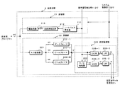
以下では、本発明の第1の実施例における超音波診断装置の構成と各ユニットの動作につき図1乃至図9を用いて説明する。尚、図1は、本実施例における超音波診断装置の全体構成を示すブロック図であり、図2及び図4は、この超音波診断装置を構成する送受信部及び超音波データ生成部のブロック図である。
(Device configuration)
In the following, the configuration of the ultrasonic diagnostic apparatus and the operation of each unit in the first embodiment of the present invention will be described with reference to FIGS. FIG. 1 is a block diagram showing the overall configuration of the ultrasonic diagnostic apparatus according to the present embodiment. FIGS. 2 and 4 are block diagrams of a transmission / reception unit and an ultrasonic data generation unit constituting the ultrasonic diagnostic apparatus. It is.
図1に示す超音波診断装置100は、1次元配列された振動素子を備え被検体に対して超音波の送受信を行なうセクタ走査用の超音波プローブ1と、前記振動素子に対して駆動信号を供給すると共に、これらの振動素子から得られた受信信号を整相加算して並列同時受信を行なう送受信部2と、送受信部2にて得られた受信信号を信号処理してBモードデータやカラードプラデータ等の超音波データを生成する超音波データ生成部3と、超音波プローブ1を、後述する超音波の走査方向に交差する方向(以下では、スライス方向と呼ぶ。)に揺動させるプローブ移動機構部4と、揺動された超音波プローブ1の位置情報(位置や方向)を検出するプローブ位置検出部5を備えている。
An ultrasonic
又、超音波診断装置100は、被検体の3次元領域における上述の走査方向及びスライス方向に対し超音波の送信方向及び受信方向を制御する送受信方向制御部6と、3次元領域における超音波データの走査方向及びスライス方向に対し所定の間隔と大きさで設定された複数の領域の各々おける複数の超音波データを合成するデータ合成部7と、前記複数の領域の各々において得られた合成後の超音波データを保存してボリュームデータを生成するボリュームデータ生成部8を備えている。
In addition, the ultrasonic
更に、超音波診断装置100は、ボリュームデータ生成部8が生成したボリュームデータを用いて2次元画像データあるいは3次元画像データを生成する画像データ生成部9と、得られた画像データを表示する表示部10と、送受信部2に対して送信超音波の中心周波数と略等しい周波数の連続波あるいは矩形波を発生する基準信号発生部11と、操作者によって被検体情報の入力、装置の初期設定、更には各種コマンド信号の入力等が行なわれる入力部12と、超音波診断装置100の各ユニットを統括的に制御するシステム制御部13を備えている。
Further, the ultrasonic
超音波プローブ1は、被検体の表面に対してその前面を接近させ超音波の送受信を行なうものであり、例えば、図示しないMo個の振動素子を有するその先端部は、カップリング溶液によって充満されたプローブケース内に収納されている。この振動素子は電気音響変換素子であり、送信時には電気的な駆動信号を送信超音波に変換し、又、受信時には超音波反射波(受信超音波)を電気信号(受信信号)に変換する機能を有している。
The
図2に示した送受信部2は、超音波プローブ1におけるMo個の振動素子に対して駆動信号を供給する送信部21と、これらの振動素子から得られた受信信号を整相加算して並列同時受信を行なう受信部22を備えている。
The transmission /
そして、送信部21は、レートパルス発生器211と、送信遅延回路212と、駆動回路213を備え、レートパルス発生器211は、基準信号発生部11から供給される連続波を分周することによって送信超音波の繰り返し周期(レート周期)を決定するレートパルスを発生する。送信遅延回路212は、送信に使用される振動素子と同数(Moチャンネル)の独立な遅延回路から構成され、送受信方向制御部6から供給される走査制御信号に基づいて所定の深さに送信超音波を収束するための遅延時間と所定の方向に送信超音波を放射するための遅延時間を前記レートパルスに与える。又、駆動回路213はMoチャンネルの独立な駆動回路を有し、超音波プローブ1に内蔵されたMo個の超音波振動子を駆動するための駆動パルスを、遅延時間が設定された上述のレートパルスに基づいて生成する。
The
一方、受信部22は、Moチャンネルから構成されるA/D変換器221と、Mチャンネルから構成されるビームフォーマ222−1乃至222−M及び直交検波部223を備えている。そして、超音波プローブ1から供給されたMoチャンネルの受信信号は、A/D変換器221にてデジタル信号に変換された後、ビームフォーマ222−1乃至222−Mに供給される。
On the other hand, the receiving
ビームフォーマ222−1乃至222−Mの各々は、図示しない受信遅延回路と加算回路を有している。そして、送受信方向制御部6から供給される走査制御信号に基づき、A/D変換器221においてデジタル信号に変換されたMoチャンネルの受信信号に対し所定の深さからの超音波反射波を収束するための収束用遅延時間と複数方向(M方向)からの受信超音波に対して強い受信指向性をもたせるための偏向用遅延時間を与えた後加算合成(整相加算)する。この場合、受信タイミングに伴って収束領域が深部に順次移動する所謂ダイナミックフォーカスを行なうことにより深さによらずに略均一なビーム幅を有した受信ビームが形成される。
Each of the beam formers 222-1 to 222-M has a reception delay circuit and an addition circuit (not shown). Then, based on the scanning control signal supplied from the transmission / reception
直交検波部223は、π/2移相器224と、Mチャンネルから構成されるミキサ225−1及び225−2、LPF(低域通過フィルタ)226−1及び226−2を備え、Mチャンネルのビームフォーマ222−1乃至222−Mから供給される整相加算後の受信信号に対し直交位相検波を行なって複素形式の受信信号(以下では、複素受信信号と呼ぶ。)を生成する。
The quadrature detection unit 223 includes a π / 2
次に、送信部21の送信遅延回路212とビームフォーマ222−1乃至222−Mにおける遅延時間の制御によって設定される並列同時受信時の超音波送受信方向につき図3を用いて説明する。但し、図3では、並列同時受信方向を4方向とした場合のセクタ走査における超音波の送信方向と受信方向について示しているが、これに限定されない。この場合、被検体に対する超音波の送信方向とこの送信方向に対応する並列同時受信方向を矢印で示した走査方向に対して順次シフトすることによりx−z平面における2次元データが収集される。但し、x方向は超音波プローブ1における振動素子の配列方向に対応し、z方向は前記振動素子の配列方向に垂直な方向を示している。
Next, the ultrasonic transmission / reception directions at the time of parallel simultaneous reception set by delay time control in the
送信部21の駆動回路213から上述の遅延時間を有する駆動信号が供給された超音波プローブ1の振動素子は、方向θ4やθ12、更にはθ20、θ28、θ36(何れも図示せず)・・・に対し送信用超音波を所定のレート周期で順次放射する。そして、方向θ4の送信超音波に対応した方向θ1、θ3、θ5及びθ7からの受信超音波を並列同時受信し、方向θ12の送信超音波に対応した方向θ9、θ11、θ13及びθ15からの受信超音波を並列同時受信する。同様にして方向θ20以降の送信超音波に対応した4方向からの受信超音波に対しても並列同時受信が行なわれる。
The vibration element of the
そして、θ1、θ3、θ5、θ7、・・・の各方向から得られた受信信号に基づいて後述の超音波データq1、q3、q5、・・・が生成され、更に、これらの超音波データに基づいてボリュームデータや画像データの生成が行なわれる。即ち、上述の方法によれば、方向θ1、θ3、θ5、θ7・・・から得られた受信信号に基づいて超音波データを生成する際、1回の送信超音波に対し4方向から受信超音波を同時に得ることができるため超音波データの生成に要する時間が非並列同時受信時に対し1/4に短縮され、従がって、後述するボリュームデータの生成におけるリアルタイム性が4倍に改善される。 Then, ultrasonic data q1, q3, q5,... Described later is generated based on the received signals obtained from the respective directions of θ1, θ3, θ5, θ7,. Volume data and image data are generated based on the above. That is, according to the method described above, when generating ultrasonic data based on the received signals obtained from the directions θ1, θ3, θ5, θ7,. Since sound waves can be obtained at the same time, the time required to generate ultrasonic data is reduced to ¼ of the time of non-parallel simultaneous reception. Accordingly, the real-time property in volume data generation described later is improved by a factor of four. The
次に、図4に示した超音波データ生成部3は、受信部22におけるMチャンネルの直交検波部223から出力された複素受信信号を信号処理してBモードデータを生成するMチャンネルのBモードデータ生成部31と、前記複素受信信号を信号処理してカラードプラデータを生成するMチャンネルのカラードプラデータ生成部32を備えている。
Next, the ultrasonic
Bモードデータ生成部31は、絶対値回路311と対数変換器312を備えている。絶対値回路311は、送受信部2の受信部22における直交検波部223から出力されたMチャンネルの複素受信信号に対する絶対値演算(例えば、LPF226−1から出力されるI成分の2乗とLPF226−2から出力されるQ成分の2乗との和の平方根)によって受信信号の包絡線を算出し、対数変換器312は、算出された包絡線に対する対数変換処理により小さな信号振幅を相対的に強調しMチャンネルのBモードデータを生成する。
The B-mode
一方、カラードプラデータ生成部32は、ドプラ信号記憶部321、MTIフィルタ322及び自己相関演算器323を備え、直交検波部223から出力された複素受信信号は、ドプラ信号記憶部321に一旦保存される。次いで、高域通過用のデジタルフィルタであるMTIフィルタ322は、ドプラ信号記憶部321に保存された複素受信信号を読み出し、この複素受信信号に対して臓器内の固定反射体あるいは臓器の呼吸性移動や拍動性移動などに起因するドプラ成分(クラッタ成分)の除去を行なう。又、自己相関演算器323は、MTIフィルタ322によって抽出された血流情報のドプラ成分に対して自己相関値を算出し、更に、この自己相関値に基づいて血流の平均速度、分散値及びパワー値を算出してMチャンネルのカラードプラデータを生成する。
On the other hand, the color Doppler
次に、図1に示したプローブ移動機構部4の具体例につき図5を用いて説明する。プローブ移動機構部4は、カップリング液46が充満されたプローブケース41の先端部に設けられている超音波プローブ1を、上述の走査方向(図3参照)に対して交差する方向(スライス方向)に揺動させる機能を有している。このプローブ移動機構部4は、超音波プローブ1が一方の先端部に固定されているアーム42と、このアーム42の他の端部が固定されている回転盤43と、ベルト44と、ベルト44を介して回転盤43と連結されたモータ45を備えている。そして、送受信方向制御部6から供給されるプローブ移動制御信号に従がってモータ45は図の矢印方向に回動し、この回動運動はベルト44を介して回転盤43及びアーム42に伝達される。そして、アーム42の先端部に固定された超音波プローブ1は、スライス方向に対して揺動する。
Next, a specific example of the probe moving
次に、上述のプローブ移動機構4が超音波プローブ1を揺動することによって収集される複数枚の2次元データにつき図6を用いて説明する。
Next, a plurality of two-dimensional data collected when the
図6(a)は、1次元配列された振動素子に供給される駆動信号の遅延時間と前記振動素子から得られる受信信号の遅延時間を制御することによって生成される2次元データs1を示している。この場合、2次元データs1を構成する放射状のq(1、1)q(1、3)、q(1、5)、・・・は、図3に示した方向θ1、θ3、θ5・・・からの受信信号に基づいて超音波データ生成部3が生成した超音波データであり、超音波データq1、q3、q5及びq7は方向θ4に対する送信超音波に対応して、又、超音波データq9、q11、q13及びq15は方向θ12に対する送信超音波に対応して得られた並列同時受信信号に基づく超音波データを示している。そして、スライス方向の所定角度に設定された超音波プローブ1の振動素子配列方向(x方向)と、このx方向に垂直なz方向によって決定されるx−z平面において超音波データq(1、1)q(1、3)、q(1、5)、・・・による2次元データs1が生成される。
FIG. 6A shows the two-dimensional data s1 generated by controlling the delay time of the drive signal supplied to the vibration elements arranged one-dimensionally and the delay time of the reception signal obtained from the vibration elements. Yes. In this case, the radial q (1,1) q (1,3), q (1,5),... Constituting the two-dimensional data s1 are the directions θ1, θ3, θ5,. The ultrasonic data generated by the ultrasonic
一方、図6(b)は、上述のプローブ移動機構部4により、超音波プローブ1をスライス方向に揺動した場合に得られる複数の2次元データを示したものであり、超音波プローブ1の揺動により、2次元データs1に交差するスライス方向において2次元データs2、s3,s4,・・・・が所定間隔で得られる。
On the other hand, FIG. 6B shows a plurality of two-dimensional data obtained when the
このように、超音波の送信とこの送信に対応した並列同時受信を走査方向において複数回繰り返すことによって所定断面における2次元データを生成し、更に、スライス方向に対する超音波プローブ1の揺動により被検体の3次元領域における連続した複数枚の2次元データが収集される。
In this way, two-dimensional data in a predetermined section is generated by repeating the transmission of ultrasonic waves and parallel simultaneous reception corresponding to the transmissions a plurality of times in the scanning direction, and further, the
図1に戻って、プローブ位置検出部5は、図示しないエンコーダを備え、プローブ移動機構部4によって揺動された超音波プローブ1の位置情報(位置や角度に関する情報)を検出する。例えば、プローブ移動機構部4に設けられたモータ45の回転軸に上述のエンコーダを装着し、このエンコーダが検出した前記回転軸の回動角度に基づいて超音波プローブ1の位置情報を検出する方法が好適であるが特に限定されない。そして、検出した位置情報は、システム制御部13を介してデータ合成部7に供給される。
Returning to FIG. 1, the probe
一方、送受信方向制御部6は、送信部21における送信遅延回路212の遅延時間及び受信部22におけるビームフォーマ222−1乃至222−Mの遅延時間を制御し、2次元データ形成面(x−z面)における超音波の送信方向と並列同時受信方向を設定する。更に、送受信方向制御部6は、プローブ移動機構部4を制御し、超音波プローブ1をスライス方向に対し所定速度あるいは所定間隔で移動する。
On the other hand, the transmission / reception
図7は、送受信方向制御部6の制御による超音波データの生成方法を模式的に示したものであり、横軸は走査方向を、又、縦軸はスライス方向に対応している。そして、第1の画像断面において生成される2次元データs1は、方向θ4に対する送信と方向θ1、θ3、θ5及びθ7に対する並列同時受信によって得られた超音波データq(1、1)、q(1、3)、q(1、5)及びq(1、7)、方向θ12に対する送信と方向θ9、θ11、θ13及びθ15に対する並列同時受信によって得られた超音波データq(1、9)、q(1、11)、q(1、13)及びq(1、15)・・・によって構成されている。
FIG. 7 schematically shows a method of generating ultrasonic data under the control of the transmission / reception
又、超音波プローブ1をスライス方向に揺動することにより前記第1の画像断面に隣接した第2の画像断面において生成される2次元データs2は、方向θ8に対する送信と方向θ5、θ7、θ9及びθ11に対する並列同時受信によって得られた超音波データq(2、5)、q(2、7)、q(2、9)及びq(2、11)、方向θ16に対する送信と方向θ13、θ15、θ17及びθ19に対する並列同時受信によって得られた超音波データq(2、13)、q(2、15)、q(2、17)及びq(2、19)・・・によって構成されている。
Further, the two-dimensional data s2 generated in the second image section adjacent to the first image section by swinging the
更に、第2の画像断面に隣接した第3の画像断面において生成される2次元データs3は、第1の画像断面における2次元データs1と同様にして方向θ4に対する送信と方向θ1、θ3、θ5及びθ7に対する並列同時受信によって得られた超音波データq(3、1)、q(3、3)、q(3、5)及びq(3、7)、方向θ12に対する送信と方向θ9、θ11、θ13及びθ15に対する並列同時受信によって得られた超音波データq(3、9)、q(3、11)、q(3、13)及びq(3、15)・・・によって構成されている。 Further, the two-dimensional data s3 generated in the third image slice adjacent to the second image slice is transmitted in the direction θ4 and the directions θ1, θ3, θ5 in the same manner as the two-dimensional data s1 in the first image slice. And θ7, and ultrasonic data q (3,1), q (3,3), q (3,5) and q (3,7) obtained by parallel simultaneous reception with respect to θ7 and transmission with respect to direction θ12 and directions θ9 and θ11. , Θ13, θ15, and ultrasonic data q (3, 9), q (3, 11), q (3, 13), q (3, 15),. .
即ち、画像断面の位置に対応させて送信方向とこの送信方向に対応した並列同時受信方向は走査方向に対して所定間隔シフトする。例えば、本実施例における奇数番目の画像断面では、方向θ4に対する送信と方向θ1、θ3、θ5及びθ7に対する並列同時受信によってスライス方向に対する超音波データの収集が開始される。これに対し偶数番目の画像断面では、方向θ8に対する送信と方向θ5、θ7、θ9及びθ11に対する並列同時受信によって超音波データの収集が開始される。 That is, the transmission direction and the parallel simultaneous reception direction corresponding to the transmission direction are shifted by a predetermined interval with respect to the scanning direction in correspondence with the position of the image cross section. For example, in the odd-numbered image section in the present embodiment, collection of ultrasonic data in the slice direction is started by transmission in the direction θ4 and parallel simultaneous reception in the directions θ1, θ3, θ5, and θ7. On the other hand, in the even-numbered image cross section, collection of ultrasonic data is started by transmission in the direction θ8 and parallel simultaneous reception in the directions θ5, θ7, θ9, and θ11.
再び図1に戻って、データ合成部7は、データ記憶部71と演算部72を備え、データ記憶部71は、超音波データ生成部3によって生成された全ての2次元データあるいは近接した複数枚の2次元データを構成する超音波データを保存する。このとき、各々の2次元データを構成する超音波データには、プローブ位置検出部5から供給される2次元データの位置情報や送受信方向制御部6から供給される受信方向の情報が付帯情報として付加される。
Returning to FIG. 1 again, the
一方、演算部72は、データ記憶部71において保存された3次元的な超音波データの中から所定範囲において近接した複数の超音波データとその付帯情報を読み出す。そして、これらの超音波データを走査方向及びスライス方向に対して合成処理すると共に、合成した超音波データの位置を前記複数の超音波データの位置情報に基づいて算出する。そして、合成処理後の超音波データとその位置情報をボリュームデータ生成部8へ供給する。
On the other hand, the
ボリュームデータ生成部8は、記憶回路を備え、データ合成部7の演算部72から供給された合成処理後の超音波データを、その付帯情報である位置情報に対応させて前記記憶回路に保存しボリュームデータを生成する。
The volume
次に、超音波データ生成部3において生成された超音波データに対してデータ合成部7が行なう合成処理につき図8及び図9を用いて説明する。図8は、データ合成部7のデータ記憶部71に保存された2次元データs1乃至s3の特性を模式的に示すものであり、2次元データs1を構成する超音波データq(1、1)q(1,3)q(1,5)、・・・、2次元データs2を構成する超音波データq(2、5)q(2,7)q(2,9)、・・・、2次元データs3を構成する超音波データq(3、1)q(3,3)q(3,5)、・・・の夫々は、既に図16及び図17において述べたように並列同時受信に起因する感度不均一、ビーム曲がり及び時相差を有している。図8において、受信感度A2は送信方向に近接した内側の受信方向における受信感度を、又、受信感度A1は外側の受信方向における受信感度を示しており、通常、A1<A2である。
Next, the synthesizing process performed by the
一方、ビーム曲がりB+及びB−は送信ビームの中心軸に近接した内側の送受信ビームにおけるビーム曲がりを、又、ビーム曲がりB2+及びB2−は外側の送受信ビームにおけるビーム曲がりを示している。但し、ここでは、B+とB−あるいはB2+とB2−は異符号でその絶対値は略等しい場合を示し、|B+|<|B2+|及び|B−|<|B2−|の関係にある。 On the other hand, the beam bends B + and B− indicate the beam bend in the inner transmission / reception beam close to the center axis of the transmission beam, and the beam bends B2 + and B2- indicate the beam bend in the outer transmission / reception beam. However, here, B + and B- or B2 + and B2- have different signs and their absolute values are substantially equal, and have a relationship of | B + | <| B2 + | and | B- | <| B2- |.
一方、図9は、データ合成部7の演算部72による合成処理を説明するための図であり、データ合成部7のデータ記憶部71には、超音波データq(1,1)、q(1,3)、q(1,5)、・・・によって構成される2次元データs1、超音波データq(2,5)、q(2,7)、q(2,9)・・・によって構成される2次元データs2、超音波データq(3,1)、q(3,3)、q(3,5)、・・・によって構成される2次元データs3・・・が夫々保存されている。そして、演算部72は、データ記憶部71に保存された上述の超音波データの中から、例えば、2次元データs1及びs2の走査方向及びスライス方向において隣接した超音波データq(1、5)、q(1、7)、q(2、5)及びq(2、7)を読み出し、これらの超音波データを合成処理することにより超音波データQ(1、5)を生成する。更に、演算部72は、上述の超音波データq(1、5)、q(1、7)、q(2、5)及びq(2、7)に付帯された夫々の位置情報に基づいてこれらの超音波データの中心位置を算出し、その位置情報を超音波データQ(1、5)に付加してボリュームデータ生成部8の記憶回路に保存する。
On the other hand, FIG. 9 is a diagram for explaining the synthesis process by the
同様にして、演算部72は、超音波データq(1、7)、q(1、9)、q(2、7)及びq(2、9)の合成処理による超音波データQ(1、7)、超音波データq(1、9)、q(1、11)、q(2、9)及びq(2、11)の合成処理による超音波データQ(1、9)、・・・・を順次生成し、更に、2次元データs2及びs3の走査方向及びスライス方向において隣接した超音波データq(2、5)、q(2、7)、q(3、5)及びq(3、7)の合成処理による超音波データQ(2、5)、超音波データq(2、7)、q(2、9)、q(3、7)及びq(3、9)の合成処理による超音波データQ(2、7)、超音波データq(2、9)、q(2、11)、q(3、9)及びq(3、11)の合成処理による超音波データQ(2、9)、・・・・を順次生成する。
Similarly, the
更に、上述の合成処理を隣接する2次元データs3とs4、s4とs5、・・・に対しても繰り返して行ない、合成処理後の超音波データに対しその位置情報を付加してボリュームデータ生成部8の記憶回路に保存する。即ち、ボリュームデータ生成部8の記憶回路には、データ合成部7の合成処理によって得られた超音波データQ(1、5)、Q(1、7)、Q(1、9)・・・Q(2、5)、Q(2、7)、Q(2、9)・・・Q(3、5)、Q(3、7)、Q(3、9)・・・がその位置情報に対応した位置に保存されてボリュームデータが生成される。
Further, the above synthesis process is repeated for the adjacent two-dimensional data s3 and s4, s4 and s5,..., And volume data is generated by adding the position information to the synthesized ultrasound data. Stored in the storage circuit of the
次に、図1の画像データ生成部9は、例えば、図示しない不透明度・色調設定部とレンダリング処理部を備えている。前記不透明度・色調設定部は、ボリュームデータ生成部8の記憶回路に保存されているボリュームデータを読み出し、これらのボリュームデータのボクセル値に基づいて不透明度や色調を設定する。一方、前記レンダリング処理部は、不透明度・色調設定部が設定した不透明度や色調の情報に基づき上述のボリュームデータをレンダリング処理してボリュームレンダリング画像データを生成する。
Next, the image
次に、表示部10は、図示しない表示用データ生成回路、変換回路及びモニタを備え、前記表示用データ生成回路は、画像データ生成部9において生成された3次元画像データあるいは2次元画像データに対し所定の表示形態に対応した走査変換処理を行なって表示用データを生成する。次いで、前記変換回路はこの表示用データに対してD/A変換とテレビフォーマット変換を行ない前記モニタに表示する。
Next, the
一方、入力部12は、操作パネル上に表示パネルやキーボード、トラックボール、マウス、選択ボタン、入力ボタン等の入力デバイスを備え、被検体情報の入力、ボリュームデータの収集条件や表示条件の設定、更には、種々のコマンド信号の入力等を行なう。
On the other hand, the
又、システム制御部13は、図示しないCPUと記憶回路を備え、操作者によって入力部12から入力あるいは設定される上述の各種情報は前記記憶回路に保存される。そして、前記CPUは、これらの情報に基づいて、送受信方向制御部6をはじめとする上述の各ユニットを統括的に制御する。
The
次に、上述のデータ合成部7によって行なわれる超音波データの合成処理の有用性につき図8及び図9を再度用いて説明する。例えば、データ合成部7のデータ記憶部71に保存された2次元データs1の超音波データq(1、5)及びq(1,7)と2次元データs2の超音波データq(2、5)及びq(2,7)を加算合成して超音波データQ(1、5)を生成する場合、超音波データQ(1、5)の感度A(1、5)及びビーム曲りB(1,5)は式(1)により定性的に示すことができる。

一方、2次元データs1の超音波データq(1、7)及びq(1,9)と2次元データs2の超音波データq(2、7)及びq(2,9)を加算合成して超音波データQ(1、7)を生成する場合においても、超音波データQ(1、7)の感度A(1、7)及びビーム曲りB(1,7)は式(1)と同等にして示される。即ち、合成処理後の超音波データでは、従来の並列同時受信において発生した感度不均一とビーム曲りの影響を排除することができ、又、時相差によって発生する塊状のパターンも上述の合成処理によって大幅に低減することが可能となる。 On the other hand, the ultrasonic data q (1,7) and q (1,9) of the two-dimensional data s1 and the ultrasonic data q (2,7) and q (2,9) of the two-dimensional data s2 are added and synthesized. Even when the ultrasonic data Q (1, 7) is generated, the sensitivity A (1, 7) and the beam bending B (1, 7) of the ultrasonic data Q (1, 7) are set to be equal to the expression (1). Shown. That is, in the ultrasonic data after the synthesis process, it is possible to eliminate the influence of sensitivity non-uniformity and beam bending that occurred in the conventional parallel simultaneous reception, and the block pattern generated due to the time difference is also obtained by the above synthesis process. It can be greatly reduced.
例えば、上述の超音波データq(1、5)、q(1、7)、q(2、5)及びq(2、7)を加算合成して生成される超音波データQ(1、5)の時相は、図8に示した時相P11と時相P21の関数となり、超音波データq(1、7)、q(1,9)、q(2、7)及びq(2、9)を加算合成して生成される超音波データQ(1、7)の時相は時相P11、時相P12及び時相P21の関数となる。同様にして超音波データQ(1、9)の時相は、時相P12と時相P21の関数となり、超音波データQ(1、11)の時相は、時相P12、時相P21及び時相P22の関数となる。 For example, the ultrasonic data Q (1, 5) generated by adding and synthesizing the above-described ultrasonic data q (1, 5), q (1, 7), q (2, 5) and q (2, 7). ) Is a function of the time phase P11 and the time phase P21 shown in FIG. 8, and the ultrasonic data q (1, 7), q (1, 9), q (2, 7) and q (2, The time phase of the ultrasonic data Q (1, 7) generated by adding and combining 9) is a function of the time phase P11, the time phase P12, and the time phase P21. Similarly, the time phase of the ultrasonic data Q (1, 9) is a function of the time phase P12 and the time phase P21, and the time phase of the ultrasonic data Q (1, 11) is the time phase P12, the time phase P21, and the time phase P21. It is a function of the time phase P22.
(画像データの生成手順)
次に、本実施例における画像データの生成手順につき図10のフローチャートに沿って説明する。尚、以下では、被検体の3次元領域において収集したBモードデータに基づいてボリュームデータを生成し、更に、このボリュームデータを用いてボリュームレンダリング画像データを生成する場合について述べるが、前記3次元領域において収集したカラードプラデータに基づいてボリュームデータを生成してもよい。又、Bモードデータやカラードプラ画像データに基づくボリュームデータを用いてサーフェイスレンダリング画像データやMIP画像データ、更には、MPR画像データ等の画像データを生成しても構わない。
(Image data generation procedure)
Next, the image data generation procedure in this embodiment will be described with reference to the flowchart of FIG. In the following, a case will be described in which volume data is generated based on B-mode data collected in a three-dimensional region of a subject, and volume rendering image data is generated using this volume data. Volume data may be generated based on the color Doppler data collected in step (1). In addition, surface rendering image data, MIP image data, and image data such as MPR image data may be generated using volume data based on B-mode data or color Doppler image data.
被検体に対する画像データの生成に先立ち、超音波診断装置100の操作者は、入力部12において被検体情報を入力すると共にボリュームデータや画像データの生成条件を設定する(図10のステップS1)。
Prior to the generation of the image data for the subject, the operator of the ultrasonic
次いで、操作者は、当該被検体の体表面に超音波プローブ1が設けられたプローブケース41の先端部を配置し、画像データの生成開始コマンドを入力する(図10のステップS2)。そして、このコマンド信号がシステム制御部13に供給されることにより、当該被検体に対する画像データの生成が開始される。
Next, the operator places the distal end portion of the probe case 41 provided with the
画像データの生成に際し、図2に示した送信部21のレートパルス発生器211は、システム制御部13から供給された制御信号に従い、当該被検体の体内に放射される送信超音波の繰り返し周期(レート周期)を決定するレートパルスを生成して送信遅延回路212に供給する。送信遅延回路212は、送受信方向制御部6から供給された制御信号に基づいて送信超音波を集束するための遅延時間と方向θ4に超音波を送信するための遅延時間を前記レートパルスに与え、このレートパルスをMoチャンネルの駆動回路213に供給する。次いで、駆動回路213は、送信遅延回路212から供給されたレートパルスに基づいて駆動信号を生成し、超音波プローブ1におけるMo個の振動素子に供給して当該被検体の方向θ4に対して超音波を送信する。
When generating the image data, the
放射された送信超音波の一部は、音響インピーダンスの異なる組織等の境界において反射し、更に、血管内で移動している血球等によってその周波数がドプラ偏移を受けた超音波反射波は超音波プローブ1の前記振動素子により受信信号に変換される。次いで、この受信信号は、受信部22のA/D変換器221においてデジタル信号に変換された後、M(M=4)チャンネルのビームフォーマ222−1乃至222−Mにおいて所定の深さからの受信超音波を収束するための遅延時間と方向θ1、θ3、θ5及びθ7からの受信超音波に対し強い受信指向性を設定するための遅延時間が与えられて整相加算される。
A part of the transmitted ultrasonic wave is reflected at the boundary between tissues with different acoustic impedances. Furthermore, the ultrasonic reflected wave whose frequency is subjected to Doppler shift by blood cells moving in the blood vessel is super It is converted into a received signal by the vibration element of the
次に、Mチャンネルから構成される直交検波部223の各々は、ビームフォーマ222−1乃至222−Mにおいて得られた方向θ1、θ3、θ5及びθ7に対応する受信信号を直交位相検波しI成分及びQ成分を有する複素受信信号に変換する。 Next, each of the quadrature detection units 223 composed of M channels performs quadrature phase detection on the received signals corresponding to the directions θ1, θ3, θ5, and θ7 obtained in the beam formers 222-1 to 222-M, and provides an I component. And a complex received signal having a Q component.
そして、超音波データ生成部3のBモードデータ生成部31は、複素受信信号のI成分及びQ成分に対して絶対値演算と対数変換を行なって超音波データとしてのBモードデータq(1、1)、q(1、3)、q(1、5)及びq(1、7)、を生成し、データ生成部7のデータ記憶部71に保存する。このとき、プローブ位置検出部5から供給される超音波プローブ1のスライス方向に対する最初の位置情報(即ち、最初の画像断面の位置情報)及び超音波の受信方向(θ1、θ3、θ5及びθ7)の情報も前記Bモードデータの付帯情報としてデータ記憶部71に保存される。
Then, the B-mode
最初の画像断面のθ1、θ3、θ5及びθ7に対するBモードデータの生成と保存が終了したならば、送受信方向制御部6は、同様にして送信部21における送信遅延回路212及び受信部22のビームフォーマ222−1乃至222−4の遅延時間を制御することにより、方向θ12、θ20、θ28、・・・の各々に対して送信超音波が所定のレート間隔で送信され、これらの送信方向の各々に対応する並列同時受信によって得られた受信信号に基づきBモードデータq(1、9)、q(1、11)、q(1、13)・・・・が生成される。そして、これらのBモードデータは、その付帯情報と共にデータ合成部7のデータ記憶部71に2次元データs1として保存される。
When the generation and storage of the B-mode data for θ1, θ3, θ5, and θ7 of the first image section is completed, the transmission / reception
第1の画像断面における2次元データs1の生成と保存が終了したならば、送受信方向制御部6は、システム制御部13からの指示信号に基づきプローブ移動機構部4に対してプローブ移動制御信号を供給し、このプローブ移動制御信号を受信したプローブ移動機構部4は、超音波プローブ1を所定角度回動させて第2の画像断面の位置に設定する。
When the generation and storage of the two-dimensional data s1 in the first image section is completed, the transmission / reception
次いで、システム制御部13は、送信部21の送信遅延回路212及び受信部22のビームフォーマ222−1乃至222−4の遅延時間を制御し、方向θ8、θ16、θ24、・・・の各々に対して超音波を所定のレート間隔で送信する。そして、送信方向の各々において4方向から並列同時受信した受信信号に基づいてBモードデータq(2、5)、q(2、7)、q(2、9)・・・・が生成され、得られたBモードデータは、その付帯情報と共にデータ記憶部71に2次元データs2として保存される。
Next, the
以下同様の手順によって、第3の画像断面におけるBモードデータq(3、1)、q(3、3)、q(3、5)・・・・、第4の画像断面におけるBモードデータq(4、5)、q(4、7)、q(4、9)・・・・の生成が順次行なわれ、2次元データs3、s4、s5、・・・としてデータ記憶部71に保存される(図10のステップS3)。
In the same manner, B mode data q (3, 1), q (3, 3), q (3, 5),... (4, 5), q (4, 7), q (4, 9),... Are sequentially generated and stored in the
次に、データ合成部7の演算部72は、データ記憶部71において保存されたBモードデータの中から所定範囲において近接した複数のBモードデータとその付帯情報を読み出し、これらのBモードデータを走査方向及びスライス方向に対して合成処理する(図10のステップS4)。更に、演算部72は、合成されたBモードデータの位置を前記複数のBモードデータの位置情報に基づいて算出し(図10のステップS5)、この位置情報を合成処理後のBモードデータに付加してボリュームデータ生成部8へ供給する。そして、このようなBモードデータの合成処理と合成されたBモードデータ位置の算出をデータ記憶部71に保存されたBモードデータの全てあるいは一部に対して繰り返し行ない、得られた合成後のBモードデータは、その位置情報と共にボリュームデータ生成部8へ供給される。
Next, the
そして、ボリュームデータ生成部8は、データ合成部7の演算部72から供給された合成処理後のBモードデータを、その付帯情報である位置情報に基づいて自己の記憶回路に配列保存しボリュームデータを生成する(図10のステップS6)。
Then, the volume
一方、画像データ生成部9の不透明度・色調設定部は、ボリュームデータ生成部8の記憶回路に保存されているボリュームデータを読み出し、これらのボリュームデータのボクセル値に基づいて不透明度や色調を設定する。次いで、画像データ生成部9のレンダリング処理部は、不透明度・色調設定部が設定した不透明度や色調の情報に基づいて上述のボリュームデータをレンダリング処理し、3次元画像データとしてのボリュームレンダリング画像データを生成して表示部10へ供給する(図10のステップS7)。
On the other hand, the opacity / tone setting unit of the image
そして、表示部10は、画像データ生成部9において生成されたボリュームレンダリング画像データに対し所定の表示形態に対応した走査変換処理を行なって表示用データを生成し、更に、D/A変換とテレビフォーマット変換を行なった後モニタに表示する(図10のステップS8)。
The
(変形例)
次に、超音波データに対してデータ合成部7が行なう合成処理の変形例につき図11乃至図13を用いて説明する。図11に示した第1の変形例における第1の画像断面の2次元データs1は、方向θ4に対する送信と方向θ1、θ3、θ5及びθ7に対する並列同時受信によって得られた超音波データq(1、1)、q(1、3)、q(1、5)及びq(1、7)、方向θ12に対する送信と方向θ9、θ11、θ13及びθ15に対する並列同時受信によって得られた超音波データq(1、9)、q(1、11)、q(1、13)及びq(1、15)・・・から構成されている。
(Modification)
Next, modified examples of the synthesis process performed by the
又、第2の画像断面において生成される2次元データs2は、方向θ6に対する送信と方向θ3、θ5、θ7及びθ9に対する並列同時受信によって得られた超音波データq(2、3)、q(2、5)、q(2、7)及びq(2、9)、方向θ14に対する送信と方向θ11、θ13、θ15及びθ17に対する並列同時受信によって得られた超音波データq(2、11)、q(2、13)、q(2、15)及びq(2、17)・・・から構成されている。 Also, the two-dimensional data s2 generated in the second image section is ultrasonic data q (2, 3), q () obtained by transmission in the direction θ6 and parallel simultaneous reception in the directions θ3, θ5, θ7, and θ9. 2, 5), q (2, 7) and q (2, 9), ultrasonic data q (2, 11) obtained by transmission with respect to direction θ14 and parallel simultaneous reception with respect to directions θ11, θ13, θ15 and θ17, q (2, 13), q (2, 15), q (2, 17)...
更に、第3の画像断面において生成される2次元データs3は、方向θ8に対する送信と方向θ5、θ7、θ9及びθ11に対する並列同時受信によって得られた超音波データq(3、5)、q(3、7)、q(3、9)及びq(3、11)、・・・、又、第4の画像断面において生成される2次元データs4は方向θ10に対する送信と方向θ7、θ9、θ11及びθ13に対する並列同時受信によって得られた超音波データq(4、7)、q(4、9)、q(4、11)及びq(4、13)・・・によって構成されている。そして、第5の画像断面以降に対しては第1の画像断面乃至第4の画像断面と同様の手順によって2次元データs5、s6、s7、・・・が生成される。 Further, the two-dimensional data s3 generated in the third image section is ultrasonic data q (3, 5), q () obtained by transmission in the direction θ8 and parallel simultaneous reception in the directions θ5, θ7, θ9, and θ11. 3, 7), q (3, 9) and q (3, 11),..., And the two-dimensional data s4 generated in the fourth image section is transmitted in the direction θ10 and the directions θ7, θ9, θ11. And ultrasonic data q (4, 7), q (4, 9), q (4, 11), q (4, 13)... Obtained by parallel simultaneous reception with respect to θ13. Then, two-dimensional data s5, s6, s7,... Are generated for the fifth and subsequent image slices by the same procedure as that for the first to fourth image slices.
次いで、データ合成部7の演算部72は、例えば、データ記憶部71に保存された超音波データの中から2次元データs1乃至s4の方向θ7に対応する超音波データq(1,7)、q(2,7)、q(3,7)及びq(4,7)を読み出し、これらの超音波データを合成処理することにより超音波データQ(2、7)を生成する。更に、演算部72は、上述の超音波データq(1,7)、q(2,7)、q(3,7)及びq(4,7)に付帯された位置情報に基づいてこれらの超音波データの中心位置を算出し、この位置情報を超音波データQ(2,7)に付加してボリュームデータ生成部8の記憶回路に保存する。
Next, the
同様にして、演算部72は、超音波データq(1、9)、q(2、9)、q(3、9)及びq(4、9)の合成処理による超音波データQ(2、9)、超音波データq(1、11)、q(2、11)、q(3、11)及びq(4、11)の合成処理による超音波データQ(2、11)、・・・・を順次生成し、更に、超音波データq(2、7)、q(3、7)、q(4、7)及びq(5、7)の合成処理による超音波データQ(3,7)、超音波データq(2、9)、q(3、9)、q(4、9)及びq(5、9)の合成処理による超音波データQ(3、9)、超音波データq(2、11)、q(3、11)、q(4、11)及びq(5、11)の合成処理による超音波データQ(3、11)、・・・・を順次生成する。
Similarly, the
一方、図12に示した第2の変形例における第1の画像断面の2次元データs1は、方向θ4に対する送信と方向θ1、θ3、θ5及びθ7に対する並列同時受信によって得られた超音波データq(1、1)、q(1、3)、q(1、5)及びq(1、7)、方向θ12に対する送信と方向θ9、θ11、θ13及びθ15に対する並列同時受信によって得られた超音波データq(1、9)、q(1、11)、q(1、13)及びq(1、15)・・・から構成され、第2の画像断面の2次元データs2も2次元データs1と同じ送信方向と並列同時受信方向によって得られた超音波データq(2、1)、q(2、3)、q(2、5)、(2、7)、(2、9)、・・・から構成されている。 On the other hand, the two-dimensional data s1 of the first image section in the second modification shown in FIG. 12 is the ultrasonic data q obtained by transmission in the direction θ4 and parallel reception in the directions θ1, θ3, θ5, and θ7. (1, 1), q (1, 3), q (1, 5) and q (1, 7), ultrasonic waves obtained by transmission in the direction θ12 and parallel simultaneous reception in the directions θ9, θ11, θ13 and θ15 Is composed of data q (1,9), q (1,11), q (1,13), q (1,15)..., And the two-dimensional data s2 of the second image section is also two-dimensional data s1. Ultrasonic data q (2,1), q (2,3), q (2,5), (2,7), (2,9) obtained by the same transmission direction and parallel simultaneous reception direction・ ・ Consists of.
一方、第3の画像断面において生成される2次元データs3は、方向θ8に対する送信と方向θ5、θ7、θ9及びθ11に対する並列同時受信によって得られた超音波データq(3、5)、q(3、7)、q(3、9)及びq(3、11)、方向θ16に対する送信と方向θ13、θ15、θ17及びθ19に対する並列同時受信によって得られた超音波データq(3、13)、q(3、15)、q(3、17)、q(3、19)・・・から構成され、第4の画像断面の2次元データs4も2次元データs3と同じ送信方向と並列同時受信方向によって得られた超音波データq(4、5)、q(4、7)、q(4、9)、q(4、11)、q(4、13)、・・・から構成されている。そして、第5の画像断面以降に対しては第1の画像断面乃至第4の画像断面と同様の手順によって2次元データs5、s6、s7、・・・が生成される。 On the other hand, the two-dimensional data s3 generated in the third image section is ultrasonic data q (3, 5), q () obtained by transmission in the direction θ8 and parallel simultaneous reception in the directions θ5, θ7, θ9, and θ11. 3, 7), q (3, 9) and q (3, 11), ultrasonic data q (3, 13) obtained by transmission with respect to direction θ16 and parallel simultaneous reception with respect to directions θ13, θ15, θ17 and θ19, q (3,15), q (3,17), q (3,19)..., and the two-dimensional data s4 of the fourth image section is also received in parallel and simultaneously in the same transmission direction as the two-dimensional data s3. It is composed of ultrasonic data q (4, 5), q (4, 7), q (4, 9), q (4, 11), q (4, 13),. Yes. Then, two-dimensional data s5, s6, s7,... Are generated for the fifth and subsequent image slices by the same procedure as that for the first to fourth image slices.
次いで、データ合成部7の演算部72は、例えば、データ記憶部71に保存された超音波データの中から2次元データs1乃至s4の方向θ5に対応する超音波データq(1,5)、q(2,5)、q(3,5)及びq(4,5)と、2次元データs1乃至s4の方向θ7に対応する超音波データq(1,7)、q(2,7)、q(3,7)及びq(4,7)を読み出し、これらの超音波データを合成処理することにより超音波データQ(2、5)を生成する。更に、演算部72は、上述の超音波データの各々に付帯された位置情報に基づいてこれらの超音波データの中心位置を算出し、その位置情報を超音波データQ(2,5)に付加してボリュームデータ生成部8の記憶回路に保存する。
Next, the
同様にして、演算部72は、超音波データq(1、7)、q(2、7)、q(3、7)及びq(4、7)と超音波データq(1、9)、q(2、9)、q(3、9)及びq(4、9)の合成処理による超音波データQ(2、7)、・・・超音波データq(2、5)、q(3、5)、q(4、5)及びq(5,5)と超音波データq(2、7)、q(3、7)、q(4、7)及びq(5,7)の合成処理による超音波データQ(3、5)、・・・・を順次生成し、更に、超音波データq(2、7)、q(3、7)、q(4、7)及びq(5、7)の合成処理による超音波データQ(3,7)、・・・・を順次生成する。
Similarly, the
上述の第1の変形例及び第2の変形例に示した超音波データの収集と合成処理によって得られた合成処理後の超音波データにおける感度A、ビーム曲りB及び時相Cも式(1)と同様にして示され、従来の並列同時受信において発生した感度不均一、ビーム曲り及び時相差の影響を排除することができる。 Sensitivity A, beam bending B, and time phase C in the ultrasonic data after the synthesis processing obtained by the collection and synthesis processing of the ultrasonic data shown in the first and second modifications are also expressed by the following equation (1). ), Which can eliminate the effects of non-uniform sensitivity, beam bending, and time difference that have occurred in conventional parallel simultaneous reception.
一方、図13は本実施例の第3の変形例を示したものであり、2次元データs1及びs2を構成する超音波データを合成処理することにより感度不均一とビーム曲りの影響が排除された2次元の超音波データを生成することが可能となる。即ち、本変形例における第1の画像断面の2次元データs1は、図9に示した上述の実施例と同様にして方向θ4に対する送信と方向θ1、θ3、θ5及びθ7に対する並列同時受信によって得られた超音波データq(1、1)、q(1、3)、q(1、5)及びq(1、7)、方向θ12に対する送信と方向θ9、θ11、θ13及びθ15に対する並列同時受信によって得られた超音波データq(1、9)、q(1、11)、q(1、13)及びq(1、15)・・・から構成されている。 On the other hand, FIG. 13 shows a third modification of the present embodiment. By combining the ultrasonic data constituting the two-dimensional data s1 and s2, the effects of non-uniform sensitivity and beam bending are eliminated. It is possible to generate two-dimensional ultrasonic data. That is, the two-dimensional data s1 of the first image section in the present modification is obtained by transmission in the direction θ4 and parallel simultaneous reception in the directions θ1, θ3, θ5, and θ7 as in the above-described embodiment shown in FIG. Transmission of ultrasonic data q (1,1), q (1,3), q (1,5) and q (1,7), direction θ12 and parallel simultaneous reception for directions θ9, θ11, θ13 and θ15 Are composed of ultrasonic data q (1, 9), q (1, 11), q (1, 13), q (1, 15).
又、第2の画像断面において生成される2次元データs2は、方向θ8に対する送信と方向θ5、θ7、θ9及びθ11に対する並列同時受信によって得られた超音波データq(2、5)、q(2、7)、q(2、9)及びq(2、11)、方向θ16に対する送信と方向θ13、θ15、θ17及びθ19に対する並列同時受信によって得られた超音波データq(2、13)、q(2、15)、q(2、17)及びq(2、19)・・・から構成されている。 Also, the two-dimensional data s2 generated in the second image section is ultrasonic data q (2, 5), q () obtained by transmission in the direction θ8 and parallel simultaneous reception in the directions θ5, θ7, θ9, and θ11. 2, 7), q (2, 9) and q (2, 11), ultrasonic data q (2, 13) obtained by transmission with respect to direction θ16 and parallel simultaneous reception with respect to directions θ13, θ15, θ17 and θ19, q (2,15), q (2,17), q (2,19)...
そして、データ合成部7の演算部72は、データ記憶部71に保存された上述の超音波データの中から、2次元データs1及びs2において走査方向及びスライス方向に隣接した超音波データq(1、5)、q(1、7)、q(2、5)及びq(2、7)を読み出し、これらの超音波データを合成処理することにより超音波データQ(1、5)を生成する。同様にして、演算部72は、上述の超音波データq(1、7)、q(1、9)、q(2、7)及びq(2、9)の合成処理による超音波データQ(1,7)、超音波データq(1、9)、q(1、11)、q(2、9)及びq(2、11)の合成処理による超音波データQ(1,9)・・・を順次生成する。この方法においても感度不均一、ビーム曲り及び時相差の影響が排除された2次元の超音波データを得ることが可能となる。
Then, the
以上述べた本発明の第1の実施例によれば、並列同時受信によって収集された被検体のボリュームデータにおいて、送受信ビームのビーム曲りや感度の不均一、更には時相差に起因するアーチファクトを低減することができる。従がって、ボリュームデータに基づいた2次元画像データあるいは3次元画像データの生成において、リアルタイム性と画質に優れた画像データの生成が可能となる。このため、診断精度が大幅に向上する。 According to the first embodiment of the present invention described above, in the volume data of the subject collected by parallel simultaneous reception, the beam bending of the transmitted / received beam, the non-uniformity of sensitivity, and the artifacts due to the time difference are reduced. can do. Accordingly, in the generation of two-dimensional image data or three-dimensional image data based on the volume data, it is possible to generate image data with excellent real-time properties and image quality. For this reason, the diagnostic accuracy is greatly improved.
特に、上述の実施例では、Bモードデータやカラードプラデータのように位相情報を有しない超音波データに対して合成処理を行なっているため、データ合成部のデータ記憶部における記憶容量を小さくすることができるのみならず合成処理に要する時間を短縮することができ、リアルタイム性が更に向上する。 In particular, in the above-described embodiment, since the synthesizing process is performed on ultrasonic data having no phase information such as B-mode data and color Doppler data, the storage capacity of the data storage unit of the data synthesis unit is reduced. In addition to being able to reduce the time required for the synthesis process, the real-time property is further improved.
次に、本発明の第2の実施例について説明する。この第2の実施例では、超音波プローブにおいて1次元配列された複数の振動素子に対する駆動信号あるいはこれらの振動素子から得られた受信信号の遅延時間を制御して走査方向に対する並列同時受信を行なうとともに、前記超音波プローブを走査方向に対して交差するスライス方向に揺動することにより走査方向に対する2次元の受信信号をスライス方向の複数箇所で生成し、被検体に対して3次元的な受信信号を収集する。 Next, a second embodiment of the present invention will be described. In the second embodiment, the parallel simultaneous reception in the scanning direction is performed by controlling the delay time of the drive signals for the plurality of vibration elements arranged one-dimensionally in the ultrasonic probe or the reception signals obtained from these vibration elements. At the same time, by swinging the ultrasonic probe in the slice direction intersecting the scanning direction, two-dimensional reception signals for the scanning direction are generated at a plurality of locations in the slice direction, and three-dimensional reception is performed for the subject. Collect signals.
次いで、前記3次元的な受信信号の各々において、走査方向及びスライス方向に対して設定された所定間隔及び所定サイズの領域に含まれる近接した複数の受信信号を合成処理し、合成後の受信信号を信号処理して得られた超音波データを保存してボリュームデータを生成する。そして、得られたボリュームデータを用いて所望の3次元画像データあるいは2次元画像データの生成と表示を行なう。 Next, in each of the three-dimensional reception signals, a plurality of adjacent reception signals included in a region having a predetermined interval and a predetermined size set in the scanning direction and the slice direction are combined, and the combined reception signal The volume data is generated by storing ultrasonic data obtained by signal processing. Then, desired 3D image data or 2D image data is generated and displayed using the obtained volume data.
(装置の構成)
本実施例における超音波診断装置と上述の第1の実施例における超音波診断装置とは特に超音波データ生成部とデータ合成部において差異がある。本実施例における超音波診断装置の構成と動作につき図14に示したブロック図を用いて説明する。尚、本実施例の超音波診断装置の全体構成を示す図14において、上述の第1の実施例のユニットと同一の動作及び機能を有するユニットは同一の符号を付加し、詳細な説明は省略する。
(Device configuration)
The ultrasonic diagnostic apparatus in the present embodiment and the ultrasonic diagnostic apparatus in the first embodiment described above are particularly different in the ultrasonic data generation unit and the data synthesis unit. The configuration and operation of the ultrasonic diagnostic apparatus in this embodiment will be described with reference to the block diagram shown in FIG. In FIG. 14, which shows the overall configuration of the ultrasonic diagnostic apparatus according to the present embodiment, units having the same operations and functions as the units of the first embodiment described above are given the same reference numerals, and detailed description thereof is omitted. To do.
図14に示す超音波診断装置200は、1次元配列された振動素子を備え被検体に対して超音波の送受信を行なうセクタ走査用の超音波プローブ1と、前記振動素子に対して駆動信号を供給すると共に、これらの振動素子から得られた受信信号を整相加算して並列同時受信を行なう送受信部2と、超音波プローブ1を、スライス方向に揺動させるプローブ移動機構部4と、揺動された超音波プローブ1の位置情報(位置や方向)を検出するプローブ位置検出部5と、被検体の3次元領域における受信信号を得るために走査方向及びスライス方向に対する超音波の送信方向及び受信方向を制御する送受信方向制御部6を備えている。
An ultrasonic
又、超音波診断装置200は、3次元領域における受信信号の走査方向及びスライス方向に対し所定の間隔と大きさで設定された複数の領域の各々における複数の受信信号を合成するデータ合成部7aと、合成された受信信号を信号処理してBモードデータ及びカラードプラデータ等の超音波データを生成する超音波データ生成部3aと、前記複数の領域の各々において得られた超音波データを順次保存してボリュームデータを生成するボリュームデータ生成部8と、このボリュームデータを用いて2次元画像データあるいは3次元画像データを生成する画像データ生成部9を備えている。
The ultrasonic
更に、超音波診断装置200は、上述の画像データ生成部9において生成された画像データを表示する表示部10と、送受信部2に対して送信超音波の中心周波数と略等しい周波数の連続波あるいは矩形波を発生する基準信号発生部11と、操作者によって被検体情報の入力、装置の初期設定、更には各種コマンド信号の入力等が行なわれる入力部12と、超音波診断装置200の各ユニットを統括的に制御するシステム制御部13を備えている。
Furthermore, the ultrasonic
そして、データ合成部7aは、データ記憶部71aと演算部72aを備え、データ記憶部71aは、当該被検体に対して設定された複数の画像断面に対して送受信部2の受信部22が生成した3次元的な複素受信信号を順次保存する。このとき、各々の複素信号には、プローブ位置検出部5が検出した画像断面の位置情報や送受信方向制御部6から供給される受信方向の情報が付帯情報として付加される。
The data synthesis unit 7a includes a data storage unit 71a and a
一方、データ合成部7aの演算部72aは、データ記憶部71aにおいて保存された3次元的な複素受信信号の中から走査方向及びスライス方向の所定範囲において近接した複数の複素受信信号とその付帯情報を読み出す。そして、これらの複素受信信号を走査方向及びスライス方向に対して合成処理すると共に、合成された複素受信信号の位置を前記複数の複素受信信号の位置情報に基づいて算出する。そして、合成処理後の複素受信信号とその位置情報を超音波データ生成部3aへ供給する。
On the other hand, the
次に、超音波データ生成部3aは、データ合成部7aの演算部72aから供給された合成後の複素受信信号を信号処理してBモードデータを生成するMチャンネルのBモードデータ生成部31aと、前記複素受信信号を信号処理してカラードプラデータを生成するMチャンネルのカラードプラデータ生成部32aを備えている。
Next, the ultrasonic data generation unit 3a includes an M-channel B-mode data generation unit 31a that generates a B-mode data by performing signal processing on the combined complex reception signal supplied from the
そして、Bモードデータ生成部31aは、図4と同様にして、前記合成後の複素受信信号に対し絶対値演算を行なってその包絡線を検出する絶対値回路311と、得られた包絡線を対数変換してMチャンネルのBモードデータを生成する対数変換器312を備えている。一方、カラードプラデータ生成部32aは、前記合成後の複素受信信号を一旦保存するドプラ信号記憶部321と、この複素受信信号に対してクラッタ成分の排除を行なうMTIフィルタ322と、MTIフィルタ322から出力された血流情報のドプラ成分に対して自己相関値を算出し、更に、この自己相関値に基づいて血流の平均速度、分散値及びパワー値を算出してMチャンネルのカラードプラデータを生成する自己相関演算器323を備えている。
Then, the B-mode data generation unit 31a performs an absolute value calculation on the combined complex received signal and detects the envelope by the same manner as in FIG. 4, and the obtained envelope is obtained. There is provided a
(画像データの生成手順)
次に、本実施例における画像データの生成手順につき図15のフローチャートに沿って説明する。当該被検体に対する画像データの生成に先立ち、超音波診断装置200の操作者は、入力部12において被検体情報を入力すると共にボリュームデータや画像データの生成条件を設定し(図15のステップS11)、当該被検体の体表近傍に超音波プローブ1を配置して画像データの生成開始コマンドを入力する(図15のステップS12)。
(Image data generation procedure)
Next, the image data generation procedure in this embodiment will be described with reference to the flowchart of FIG. Prior to the generation of the image data for the subject, the operator of the ultrasonic
画像データの生成に際し、システム制御部13は、上述の第1の実施例と同様の手順により送受信部2の送信部21における送信遅延回路212及び受信部22におけるビームフォーマ222−1乃至222−Mの遅延時間を制御し、第1の画像断面の走査方向に対し並列同時受信法を適用した超音波の送受信を順次行なう。そして、受信部22の直交位相検波部223から出力された前記第1の画像断面における2次元的な複素受信信号はデータ合成部7aのデータ記憶部71aに保存される。このとき、プローブ位置検出部5から供給される超音波プローブ1のスライス方向に対する位置情報(即ち、第1の画像断面の位置情報)及び超音波の受信方向の情報も複素受信信号の付帯情報としてデータ記憶部71aに保存される。
When generating the image data, the
一方、送受信方向制御部6はプローブ移動機構部4を制御し、プローブ移動機構部4は超音波プローブ1を所定角度回動させて第2の画像断面、第3の画像断面・・・に設定する。そして、第1の画像断面の場合と同様にして各々の画像断面においても2次元的な複素受信信号の収集が行なわれ、得られた3次元的な複素受信信号はその付帯情報と共にデータ記憶部71aに保存される(図15のステップS13)。
On the other hand, the transmission / reception
次に、データ合成部7aの演算部72aは、データ記憶部71aにおいて保存された3次元的な複素受信信号の中から所定範囲において近接した複数の複素受信信号とその付帯情報(位置情報)を読み出し、これらの複素受信信号を走査方向及びスライス方向に対して合成処理する(図15のステップS14)。更に、演算部72aは、合成された複素受信信号の位置を前記複数の複素受信信号の位置情報に基づいて算出し(図15のステップS15)、この位置情報を合成処理後の複素受信信号に付加して超音波データ生成部3aへ供給する。そして、このような複素受信信号の合成処理と合成された複素受信信号の位置算出をデータ記憶部71aに保存された複素受信信号の全てあるいは一部に対して繰り返し行ない、得られた合成後の複素受信信号をその位置情報と共に超音波データ生成部3aへ供給する。
Next, the
そして、超音波データ生成部3aは、I成分及びQ成分を有する複素受信信号を信号処理して超音波データを生成し(図15のステップS16)、前記複素受信信号の位置情報を付加してボリュームデータ生成部8へ供給する。
Then, the ultrasonic data generation unit 3a performs signal processing on the complex reception signal having the I component and the Q component to generate ultrasonic data (step S16 in FIG. 15), and adds the position information of the complex reception signal. This is supplied to the volume
次いで、ボリュームデータ生成部8は、超音波データ生成部3aから供給された超音波データを、その付帯情報である位置情報に基づいて自己の記憶回路に配列保存しボリュームデータを生成する(図15のステップS17)。
Next, the volume
一方、画像データ生成部9は、ボリュームデータ生成部8の記憶回路に保存されているボリュームデータを読み出し、このボリュームデータに対して所定の画像処理を行なって3次元画像データ等の画像データを生成する(図15のステップS18)。
On the other hand, the image
そして、表示部10は、画像データ生成部9において生成された画像データに対し所定の表示形態に対応した走査変換処理を行なって表示用データを生成し、更に、D/A変換とテレビフォーマット変換を行なった後モニタに表示する(図15のステップS19)。
The
尚、第1の実施例における第1の変形例乃至第3の変形例で示した超音波データの合成方法は第2の実施例における受信信号の合成に対してもそのまま適用することができる。 The method for synthesizing ultrasonic data shown in the first to third modifications in the first embodiment can be applied as it is to the synthesis of received signals in the second embodiment.
以上述べた本発明の第2の実施例によれば、並列同時受信によって収集された被検体のボリュームデータにおいて、送受信ビームのビーム曲りや感度の不均一、更には時相差に起因するアーチファクトを低減することができる。従がって、ボリュームデータに基づいた2次元画像データあるいは3次元画像データの生成において、リアルタイム性と画質に優れた画像データの生成が可能となる。このため、診断精度が大幅に向上する。 According to the second embodiment of the present invention described above, in the volume data of the subject collected by parallel simultaneous reception, the beam bending of the transmitted / received beam, nonuniform sensitivity, and artifacts due to the time difference are reduced. can do. Accordingly, in the generation of two-dimensional image data or three-dimensional image data based on the volume data, it is possible to generate image data with excellent real-time properties and image quality. For this reason, the diagnostic accuracy is greatly improved.
又、上述の実施例では、位相情報を有した受信信号に対して合成処理を行なっているため、特に、ビーム曲りに対しては厳密な補正を行なうことができるため、更に良好な画質を有した画像データを得ることができる。 Further, in the above-described embodiment, since the synthesizing process is performed on the reception signal having the phase information, it is possible to perform a strict correction especially for the beam bending, so that the image quality is further improved. Image data can be obtained.
以上、本発明の実施例について述べてきたが、本発明は上述の実施例に限定されるものではなく、変形して実施することが可能である。例えば、上述の実施例では、複数の振動素子が1次元配列されたセクタ走査用の超音波プローブ1を更に機械的に揺動させることによってボリュームデータを収集する場合について述べたが、リニア走査方式あるいはコンベックス走査方式の超音波プローブを揺動させてもよく、又、上述の各走査方式における超音波プローブを並行移動させてもよい。更に、振動素子が2次元配列された、所謂、2次元アレイ超音波プローブを用いてボリュームデータの収集を行なってもよい。
As mentioned above, although the Example of this invention has been described, this invention is not limited to the above-mentioned Example, It can change and implement. For example, in the above-described embodiment, the case where the volume data is collected by further mechanically swinging the
例えば、図12に示した第2の変形例において2次元アレイ超音波プローブを用いM=8の並列同時受信を行なう場合、送信ビームの中心位置を2次元データs1のスライス断面と2次元データs2のスライス断面との間に設定し、更に、走査方向をθ4に設定した状態で、2次元データs1のスライス断面におけるθ1、θ3、θ5、θ7及び2次元データs2のスライス断面におけるθ1、θ3、θ5、θ7からの受信信号を同時に受信することにより、感度不均一、ビーム曲り及び時相差の影響は排除され、リアルタイム性は2倍に向上する。このため、診断能は更に向上する。 For example, in the second modified example shown in FIG. 12, when performing parallel parallel reception of M = 8 using a two-dimensional array ultrasonic probe, the center position of the transmission beam is set to the slice section of the two-dimensional data s1 and the two-dimensional data s2. Are set between the slice cross sections of the two-dimensional data s1 and θ1, θ3, θ5, θ7 in the slice cross-section of the two-dimensional data s1 and θ1, θ3, By simultaneously receiving the received signals from θ5 and θ7, the effects of non-uniform sensitivity, beam bending, and time phase difference are eliminated, and the real-time property is improved twice. For this reason, the diagnostic ability is further improved.
又、被検体の3次元領域において収集したBモードデータに基づいてボリュームデータを生成し、更に、このボリュームデータを用いてボリュームレンダリング画像データを生成する場合について述べたが、前記3次元領域において収集したカラードプラデータに基づいてボリュームデータを生成してもよい。又、Bモードデータやカラードプラ画像データに基づくボリュームデータを用いてサーフェイスレンダリング画像データやMIP画像データ、更には、MPR画像データ等の画像データを生成しても構わない。 In addition, the volume data is generated based on the B-mode data collected in the three-dimensional area of the subject, and the volume rendering image data is generated using the volume data. However, the volume data is collected in the three-dimensional area. Volume data may be generated based on the color Doppler data. In addition, surface rendering image data, MIP image data, and image data such as MPR image data may be generated using volume data based on B-mode data or color Doppler image data.
一方、上述のスライス方向は、通常、走査方向に対して垂直な方向に設定されるが、これに限定されるものではなく、任意の方向に設定してもよい。又、位相情報を有する受信信号は、上述の実施例のようにI成分及びQ成分を有する複素型の受信信号であってもよいが、振動波形を有する受信信号であってもよい。 On the other hand, the slice direction described above is normally set in a direction perpendicular to the scanning direction, but is not limited to this, and may be set in any direction. The reception signal having phase information may be a complex reception signal having an I component and a Q component as in the above-described embodiment, or may be a reception signal having a vibration waveform.
更に、並列同時受信における受信方向数、あるいは、受信信号や超音波データが合成される領域の設定は上述の実施例あるいはその変形例に示したものに限定されるものではない。 Furthermore, the number of reception directions in parallel simultaneous reception, or the setting of a region where received signals and ultrasonic data are combined is not limited to that shown in the above-described embodiments or modifications thereof.
1…超音波プローブ
2…送受信部
21…送信部
22…受信部
3、3a…超音波データ生成部
31、31a…Bモードデータ生成部
32、32a…カラードプラデータ生成部
4…プローブ移動機構部
5…プローブ位置検出部
6…送受信方向制御部
7、7a…データ合成部
71、71a…データ記憶部
72、72a…演算部
8…ボリュームデータ生成部
9…画像データ生成部
10…表示部
11…基準信号発生部
12…入力部
13…システム制御部
100、200…超音波診断装置
DESCRIPTION OF
Claims (15)
方向における並列同時受信によって得られる2次元的な超音波データを前記走査方向と交
差するスライス方向の複数断面にて収集し、このとき得られた3次元的な超音波データに
基づいて画像データを生成する超音波診断装置において、
前記走査方向及び前記スライス方向に対する超音波の送信方向及び受信方向を制御する
送受信方向制御手段と、
前記送信方向及び受信方向を制御した超音波の送受信に基づいて得られた前記3次元的
な超音波データに基づいてデータを合成処理し超音波データを生成するデータ合成手段と
、
前記超音波データに基づいて画像データを生成する画像データ生成手段とを備え、
前記送受信方向制御手段は、前記並列同時受信における送信方向及び受信方向群の走査
方向に対する位置を、前記スライス方向の位置が異なる断面ごとに所定間隔シフトして、
前記走査方向に対する超音波走査を行う
ことを特徴とする超音波診断装置。 Using an ultrasonic probe having a vibrating element for transmitting and receiving ultrasonic waves, a plurality of 2-dimensional ultrasound data obtained by the parallel simultaneous reception in the scanning direction along the Jo Tokoro cross-section of a slice direction crossing the scanning direction In an ultrasonic diagnostic apparatus that collects in a cross section and generates image data based on the three- dimensional ultrasonic data obtained at this time,
A transmission / reception direction control means for controlling a transmission direction and a reception direction of ultrasonic waves relative to the scanning direction and the slice direction;
The three-dimensional data obtained based on transmission / reception of ultrasonic waves in which the transmission direction and the reception direction are controlled.
Data synthesizing means for synthesizing the data based on the ultrasonic data and generating ultrasonic data ;
Image data generating means for generating image data based on the ultrasonic data,
The transmission / reception direction control means scans the transmission direction and reception direction group in the parallel simultaneous reception.
The position with respect to the direction is shifted by a predetermined interval for each cross section having a different position in the slice direction,
An ultrasonic diagnostic apparatus that performs ultrasonic scanning in the scanning direction.
パターンを少なくとも第1のパターンと第2のパターンの2種類有し、前記スライス方向のThere are at least two types of patterns, a first pattern and a second pattern, in the slice direction
断面ごとに前記配置パターンを切り替えることにより前記シフトを行うThe shift is performed by switching the arrangement pattern for each cross section.
ことを特徴とする請求項1に記載の超音波診断装置。The ultrasonic diagnostic apparatus according to claim 1.
方向に対する位置のシフトを、前記スライス方向の断面位置の移動に連動して行うThe position is shifted relative to the direction in conjunction with the movement of the cross-sectional position in the slice direction.
ことを特徴とする請求項1または2に記載の超音波診断装置。The ultrasonic diagnostic apparatus according to claim 1 or 2.
成するボリュームデータ生成手段を備え、前記画像データ生成手段は、前記ボリュームデ
ータに対し所定の処理を行なって2次元画像データあるいは3次元画像データを生成する
ことを特徴とする請求項1乃至3のいずれか1項に記載の超音波診断装置。 Volume data generation means for generating volume data by storing the synthesized ultrasonic data corresponding to the position information and generating volume data, the image data generation means performing a predetermined process on the volume data to generate a two-dimensional image the ultrasonic diagnostic apparatus according to any one of claims 1 to 3, characterized in that to generate the data or 3-dimensional image data.
における前記複数の超音波データの位置情報に基づいて算出することを特徴とする請求項
4記載の超音波診断装置。 The data synthesizing unit calculates position information of the synthesized ultrasound data based on position information of the plurality of ultrasound data in each of the plurality of regions.
4. The ultrasonic diagnostic apparatus according to 4 .
査方向における並列同時受信によって得られる2次元的な受信信号を前記走査方向と交差
するスライス方向の複数断面にて収集し、このとき得られた3次元的な受信信号に基づい
て画像データを生成する超音波診断装置において、
前記走査方向及び前記スライス方向に対する超音波の送信方向及び受信方向を制御する送
受信方向制御手段と、
前記送信方向及び受信方向を制御した超音波の送受信に基づいて得られた前記3次元的な
受信信号を合成処理するデータ合成手段と、
合成された受信信号に基づいて画像データを生成する画像データ生成手段とを備え、
前記送受信方向制御手段は、前記並列同時受信における送信方向及び受信方向群の走査方
向に対する位置を、前記スライス方向の位置が異なる断面ごとに所定間隔シフトして、前
記走査方向に対する超音波走査を行なうことを特徴とする超音波診断装置。 Using an ultrasonic probe having a vibrating element for transmitting and receiving ultrasonic waves, a plurality sectional slice direction crossing the scanning direction of two-dimensional reception signal obtained by the parallel simultaneous reception in the scanning direction along the Jo Tokoro cross In the ultrasonic diagnostic apparatus that generates image data based on the three- dimensional received signal obtained at this time,
A transmission / reception direction control means for controlling a transmission direction and a reception direction of ultrasonic waves relative to the scanning direction and the slice direction;
The three-dimensional obtained based on transmission / reception of ultrasonic waves in which the transmission direction and the reception direction are controlled.
Data synthesizing means for synthesizing the received signal ;
Image data generating means for generating image data based on the synthesized received signal,
The transmission / reception direction control means is configured to scan the transmission direction and the reception direction group in the parallel simultaneous reception.
An ultrasonic diagnostic apparatus that performs ultrasonic scanning in the scanning direction by shifting a position with respect to a direction by a predetermined interval for each cross section having a different position in the slice direction .
と、前記超音波データを前記合成された受信信号の位置情報に対応させて保存することに
よりボリュームデータを生成するボリュームデータ生成手段を備え、前記画像データ生成
手段は、前記ボリュームデータに対し所定の処理を行なって2次元画像データあるいは3
次元画像データを生成することを特徴とする請求項6記載の超音波診断装置。 Ultrasonic data generation means for generating ultrasonic data by performing signal processing on the combined received signal, and generating volume data by storing the ultrasonic data in correspondence with position information of the combined received signal Volume data generation means for performing two-dimensional image data or 3D by performing predetermined processing on the volume data.
7. The ultrasonic diagnostic apparatus according to claim 6, wherein the two- dimensional image data is generated.
ける前記複数の受信信号の位置情報に基づいて算出し、前記ボリュームデータ生成手段は
、前記超音波データを前記合成された受信信号の位置情報に対応させて保存し前記ボリュ
ームデータを生成することを特徴とする請求項7記載の超音波診断装置。 The data synthesizing unit calculates position information of the synthesized received signal based on position information of the plurality of received signals in each of the plurality of regions, and the volume data generating unit is configured to synthesize the ultrasonic data. 8. The ultrasonic diagnostic apparatus according to claim 7, wherein the volume data is generated by storing the received data in correspondence with position information of the received signal.
いは移動させることにより前記スライス方向に対する超音波の送信方向及び受信方向を制
御することを特徴とする請求項1又は請求項6に記載した超音波診断装置。 The transmission / reception direction control means controls the transmission direction and reception direction of ultrasonic waves relative to the slice direction by swinging or moving the ultrasonic probe relative to the slice direction. Item 7. The ultrasonic diagnostic apparatus according to Item 6 .
受信信号を加算処理することを特徴とする請求項1又は請求項6に記載した超音波診断装
置。 Said data synthesizing means, the ultrasonic diagnostic apparatus according to claim 1 or claim 6, characterized in that addition processing the plurality of ultrasound data or the received signal at each of said plurality of regions.
行ない、前記データ合成手段は、前記スライス方向に隣接した2つの超音波データあるい
は受信信号と前記走査方向において前記2つの超音波データあるいは受信信号の各々と隣
接した2つの超音波データあるいは受信信号を合成処理することを特徴とする請求項1又
は請求項6に記載した超音波診断装置。 The transmission / reception direction control means performs control for four-way parallel simultaneous reception with respect to the scanning direction, and the data synthesis means includes two ultrasonic data or reception signals adjacent to the slice direction and the two in the scanning direction. The ultrasonic diagnostic apparatus according to claim 1 or 6 , wherein two ultrasonic data or reception signals adjacent to each of the two ultrasonic data or reception signals are combined.
行ない、前記データ合成手段は、前記スライス方向に近接した4つの超音波データあるい
は受信信号を合成処理することを特徴とする請求項1又は請求項6に記載した超音波診断
装置。 The transmission / reception direction control unit performs control for four-way parallel simultaneous reception with respect to the scanning direction, and the data synthesis unit synthesizes four ultrasonic data or reception signals close to the slice direction. The ultrasonic diagnostic apparatus according to claim 1 or 6 .
行ない、前記データ合成手段は、前記スライス方向に近接した4つの超音波データあるい
は受信信号と前記走査方向において前記4つの超音波データあるいは受信信号の各々と隣
接した4つの超音波データあるいは受信信号を合成処理することを特徴とする請求項1又
は請求項6に記載した超音波診断装置。 The transmission / reception direction control means performs control for four-way parallel simultaneous reception with respect to the scanning direction, and the data synthesizing means performs four ultrasonic data or reception signals close to the slice direction and the four in the scanning direction. The ultrasonic diagnostic apparatus according to claim 1 or 6 , wherein four ultrasonic data or reception signals adjacent to each of the ultrasonic data or reception signals are combined.
査方向における並列同時受信によって得られる2次元的な超音波データを前記走査方向と
交差するスライス方向の複数断面にて収集し、このとき得られた3次元的な超音波データ
に基づいて画像データを生成する画像データ生成方法であって、
送受信方向制御手段が、前記並列同時受信における送信方向及び受信方向群の走査方向
に対する位置を、前記スライス方向の位置が異なる断面ごとに所定間隔シフトして、前記
走査方向に対する超音波走査を行なうと共に、前記断面のスライス方向への移動を行なっ
て3次元的な超音波データを収集するステップと、
データ合成手段が、前記走査方向及びスライス方向に対して前記3次元的な超音波データ
の合成処理を行なうステップと、
前記データ合成手段が、合成された超音波データの位置情報を前記複数の超音波データの
位置情報に基づいて算出するステップと、
ボリュームデータ生成手段が、前記合成された超音波データをその位置情報に対応させて
保存しボリュームデータを生成するステップと、
画像データ生成手段が、前記ボリュームデータを用いて2次元あるいは3次元の画像デー
タを生成するステップとを
有することを特徴とする画像データ生成方法。 Using an ultrasonic probe having a vibrating element for transmitting and receiving ultrasonic waves, a plurality of 2-dimensional ultrasound data obtained by the parallel simultaneous reception in the scanning direction along the Jo Tokoro cross-section of a slice direction crossing the scanning direction An image data generation method for generating image data based on three- dimensional ultrasonic data acquired at a cross section and obtained at this time,
The transmission / reception direction control means includes a transmission direction and a scanning direction of the reception direction group in the parallel simultaneous reception.
The position is shifted by a predetermined interval for each cross section having a different position in the slice direction,
Performs ultrasonic scanning in the scanning direction and moves the cross section in the slice direction
And collecting the 3-dimensional ultrasound data Te,
Data synthesizing means for the three-dimensional ultrasonic data with respect to the scanning direction and the slice direction.
Performing the synthesis process of
The data synthesis means calculating position information of the synthesized ultrasonic data based on the position information of the plurality of ultrasonic data;
A volume data generating means storing the synthesized ultrasonic data in correspondence with the position information and generating volume data;
An image data generation means comprising: a step of generating two-dimensional or three-dimensional image data using the volume data.
査方向における並列同時受信によって得られる2次元的な受信信号を前記走査方向と交差
するスライス方向の複数断面にて収集し、このとき得られた3次元的な受信信号に基づい
て画像データを生成する画像データ生成方法であって、
送受信方向制御手段が、前記並列同時受信における送信方向及び受信方向群の走査方向に
対する位置を、前記スライス方向の位置が異なる断面ごとに所定間隔シフトして、前記走
査方向に対する超音波走査を行うと共に、前記断面のスライス方向への移動を行って3次
元的な受信信号を収集するステップと、
データ合成手段が、前記走査方向及びスライス方向に対して前記3次元的な受信信号の合
成処理を行うステップと、
前記データ合成手段が、合成された受信信号の位置情報を前記複数の受信信号の位置情報
に基づいて算出するステップと、
超音波データ生成手段が、前記合成された受信信号を処理して超音波データを生成するス
テップと、
ボリュームデータ生成手段が、前記超音波データを前記合成された受信信号の位置情報に
対応させて保存しボリュームデータを生成するステップと、
画像データ生成手段が、前記ボリュームデータを用いて2次元あるいは3次元の画像デー
タを生成するステップとを
有することを特徴とする画像データ生成方法。 Using an ultrasonic probe having a vibrating element for transmitting and receiving ultrasonic waves, a plurality sectional slice direction crossing the scanning direction of two-dimensional reception signal obtained by the parallel simultaneous reception in the scanning direction along the Jo Tokoro cross And generating image data based on the three- dimensional received signal obtained at this time,
A transmission / reception direction control means is provided in the transmission direction and the scanning direction of the reception direction group in the parallel simultaneous reception.
The position is shifted by a predetermined interval for each cross section having a different position in the slice direction, and the scan is performed.
Performing ultrasonic scanning with respect to the inspection direction and performing movement in the slice direction of the cross section to collect a three-dimensional received signal;
A step of performing data synthesizing processing of the three-dimensional received signal in the scanning direction and the slice direction ;
The data combining means calculating position information of the combined received signal based on the position information of the plurality of received signals;
An ultrasonic data generating means that processes the combined received signal to generate ultrasonic data;
A volume data generating means storing the ultrasonic data in correspondence with the position information of the synthesized received signal and generating volume data;
An image data generation means comprising: a step of generating two-dimensional or three-dimensional image data using the volume data.
Priority Applications (2)
| Application Number | Priority Date | Filing Date | Title |
|---|---|---|---|
| JP2006252570A JP4881112B2 (en) | 2006-09-19 | 2006-09-19 | Ultrasonic diagnostic apparatus and image data generation method |
| US11/857,917 US9316725B2 (en) | 2006-09-19 | 2007-09-19 | Ultrasound diagnostic apparatus and method for acquiring ultrasound data |
Applications Claiming Priority (1)
| Application Number | Priority Date | Filing Date | Title |
|---|---|---|---|
| JP2006252570A JP4881112B2 (en) | 2006-09-19 | 2006-09-19 | Ultrasonic diagnostic apparatus and image data generation method |
Publications (2)
| Publication Number | Publication Date |
|---|---|
| JP2008073085A JP2008073085A (en) | 2008-04-03 |
| JP4881112B2 true JP4881112B2 (en) | 2012-02-22 |
Family
ID=39345781
Family Applications (1)
| Application Number | Title | Priority Date | Filing Date |
|---|---|---|---|
| JP2006252570A Active JP4881112B2 (en) | 2006-09-19 | 2006-09-19 | Ultrasonic diagnostic apparatus and image data generation method |
Country Status (2)
| Country | Link |
|---|---|
| US (1) | US9316725B2 (en) |
| JP (1) | JP4881112B2 (en) |
Families Citing this family (9)
| Publication number | Priority date | Publication date | Assignee | Title |
|---|---|---|---|---|
| WO2005058167A2 (en) * | 2003-12-02 | 2005-06-30 | Hitachi Medical Corp | Ultrasonographic device |
| JP2008229096A (en) * | 2007-03-22 | 2008-10-02 | Toshiba Corp | Ultrasonic diagnostic apparatus |
| JP5627171B2 (en) * | 2008-06-26 | 2014-11-19 | 株式会社東芝 | Ultrasonic diagnostic equipment |
| US8279705B2 (en) | 2010-10-20 | 2012-10-02 | Kabushiki Kaisha Toshiba | Ultrasonic diagnostic apparatus and ultrasonic transmission/reception method |
| WO2012053345A1 (en) * | 2010-10-20 | 2012-04-26 | 株式会社 東芝 | Ultrasound diagnostic apparatus and ultrasonic wave sending and receiving method |
| US9354204B2 (en) * | 2011-10-14 | 2016-05-31 | General Electric Company | Ultrasonic tomography systems for nondestructive testing |
| US10456110B2 (en) * | 2014-07-17 | 2019-10-29 | Hitachi, Ltd. | Ultrasound imaging apparatus |
| CN107802287B (en) * | 2017-11-16 | 2020-05-19 | 深圳纯和医药有限公司 | Method for improving imaging stability of 4D mechanical probe of ultrasonic diagnostic apparatus |
| US11540812B2 (en) * | 2018-12-21 | 2023-01-03 | General Electric Company | Method and system for increasing effective line density of volume compound ultrasound images |
Family Cites Families (99)
| Publication number | Priority date | Publication date | Assignee | Title |
|---|---|---|---|---|
| US5027658A (en) * | 1986-05-02 | 1991-07-02 | Anderson Forrest L | Three dimensional imaging method and device using ellipsoidal backprojection with arbitrarily shaped pulses |
| JP3090718B2 (en) * | 1990-07-11 | 2000-09-25 | 株式会社東芝 | Ultrasound diagnostic equipment |
| JPH05237116A (en) * | 1991-06-12 | 1993-09-17 | Yokogawa Medical Syst Ltd | Ultrasonic diagnostic device |
| US5235982A (en) * | 1991-09-30 | 1993-08-17 | General Electric Company | Dynamic transmit focusing of a steered ultrasonic beam |
| US5318033A (en) * | 1992-04-17 | 1994-06-07 | Hewlett-Packard Company | Method and apparatus for increasing the frame rate and resolution of a phased array imaging system |
| JP3329485B2 (en) * | 1992-06-15 | 2002-09-30 | 株式会社東芝 | Ultrasound diagnostic equipment |
| US6005916A (en) * | 1992-10-14 | 1999-12-21 | Techniscan, Inc. | Apparatus and method for imaging with wavefields using inverse scattering techniques |
| US5441052A (en) * | 1992-12-28 | 1995-08-15 | Kabushiki Kaisha Toshiba | Color doppler-type ultrasonic diagnostic apparatus |
| JPH06209941A (en) * | 1993-01-18 | 1994-08-02 | Toshiba Corp | Ultrasonic diagnosing device |
| US5433202A (en) * | 1993-06-07 | 1995-07-18 | Westinghouse Electric Corporation | High resolution and high contrast ultrasound mammography system with heart monitor and boundary array scanner providing electronic scanning |
| JPH078492A (en) | 1993-06-28 | 1995-01-13 | Toshiba Corp | Ultrasonic diagnostic device |
| JPH07265314A (en) * | 1994-03-31 | 1995-10-17 | Hitachi Medical Corp | Ultrasonic tomographic apparatus |
| US5560362A (en) * | 1994-06-13 | 1996-10-01 | Acuson Corporation | Active thermal control of ultrasound transducers |
| US5555534A (en) * | 1994-08-05 | 1996-09-10 | Acuson Corporation | Method and apparatus for doppler receive beamformer system |
| US5460180A (en) * | 1994-09-30 | 1995-10-24 | Siemens Medical Systems, Inc. | Connection arrangement and method of operation of a 2D array for phase aberration correction |
| US5517995A (en) * | 1994-09-30 | 1996-05-21 | Siemens Medical Systems, Inc. | 2D array for phase aberration correction |
| US5546807A (en) * | 1994-12-02 | 1996-08-20 | Oxaal; John T. | High speed volumetric ultrasound imaging system |
| US5678554A (en) * | 1996-07-02 | 1997-10-21 | Acuson Corporation | Ultrasound transducer for multiple focusing and method for manufacture thereof |
| US5899861A (en) * | 1995-03-31 | 1999-05-04 | Siemens Medical Systems, Inc. | 3-dimensional volume by aggregating ultrasound fields of view |
| JPH09526A (en) * | 1995-06-22 | 1997-01-07 | Toshiba Corp | Ultrasonic diagnostic device |
| US6248073B1 (en) * | 1995-06-29 | 2001-06-19 | Teratech Corporation | Ultrasound scan conversion with spatial dithering |
| US5904652A (en) * | 1995-06-29 | 1999-05-18 | Teratech Corporation | Ultrasound scan conversion with spatial dithering |
| US5573001A (en) * | 1995-09-08 | 1996-11-12 | Acuson Corporation | Ultrasonic receive beamformer with phased sub-arrays |
| DE69736549T2 (en) * | 1996-02-29 | 2007-08-23 | Acuson Corp., Mountain View | SYSTEM, METHOD AND CONVERTER FOR ORIENTING MULTIPLE ULTRASOUND IMAGES |
| US5720291A (en) * | 1996-03-22 | 1998-02-24 | Advanced Technology Laboratories, Inc. | Three dimensional medical ultrasonic diagnostic image of tissue texture and vasculature |
| US5680863A (en) * | 1996-05-30 | 1997-10-28 | Acuson Corporation | Flexible ultrasonic transducers and related systems |
| US5673699A (en) * | 1996-05-31 | 1997-10-07 | Duke University | Method and apparatus for abberation correction in the presence of a distributed aberrator |
| JPH10118063A (en) * | 1996-10-24 | 1998-05-12 | Aloka Co Ltd | Ultrasonograph |
| US6086539A (en) * | 1996-12-04 | 2000-07-11 | Acuson Corporation | Methods and apparatus for ultrasound image quantification |
| US6030344A (en) * | 1996-12-04 | 2000-02-29 | Acuson Corporation | Methods and apparatus for ultrasound image quantification |
| US6292433B1 (en) * | 1997-02-03 | 2001-09-18 | Teratech Corporation | Multi-dimensional beamforming device |
| US6721235B2 (en) * | 1997-02-03 | 2004-04-13 | Teratech Corporation | Steerable beamforming system |
| US6126603A (en) * | 1997-05-07 | 2000-10-03 | General Electric Company | Method and apparatus for segmenting color flow mode data using velocity information in three-dimensional ultrasound imaging |
| US5865750A (en) * | 1997-05-07 | 1999-02-02 | General Electric Company | Method and apparatus for enhancing segmentation in three-dimensional ultrasound imaging |
| US5897501A (en) * | 1997-05-07 | 1999-04-27 | General Electric Company | Imaging system with multiplexer for controlling a multi-row ultrasonic transducer array |
| US5779641A (en) * | 1997-05-07 | 1998-07-14 | General Electric Company | Method and apparatus for three-dimensional ultrasound imaging by projecting filtered pixel data |
| US6102864A (en) * | 1997-05-07 | 2000-08-15 | General Electric Company | Three-dimensional ultrasound imaging of velocity and power data using average or median pixel projections |
| US5899863A (en) * | 1997-05-07 | 1999-05-04 | General Electric Company | Method and apparatus for segmenting B-mode intensity data using doppler shift data in three-dimensional ultrasound imaging |
| US5954653A (en) * | 1997-05-07 | 1999-09-21 | General Electric Company | Method and apparatus for automatically enhancing contrast in projected ultrasound image |
| US5882309A (en) * | 1997-05-07 | 1999-03-16 | General Electric Company | Multi-row ultrasonic transducer array with uniform elevator beamwidth |
| US5840032A (en) * | 1997-05-07 | 1998-11-24 | General Electric Company | Method and apparatus for three-dimensional ultrasound imaging using transducer array having uniform elevation beamwidth |
| US5904653A (en) * | 1997-05-07 | 1999-05-18 | General Electric Company | Method and apparatus for three-dimensional ultrasound imaging combining intensity data with color flow velocity or power data |
| US6269262B1 (en) * | 1997-06-20 | 2001-07-31 | Hitachi, Ltd. | Biomagnetic field measuring apparatus |
| JP3806229B2 (en) * | 1997-06-27 | 2006-08-09 | アロカ株式会社 | Ultrasonic diagnostic equipment |
| US5876342A (en) * | 1997-06-30 | 1999-03-02 | Siemens Medical Systems, Inc. | System and method for 3-D ultrasound imaging and motion estimation |
| US6867720B1 (en) * | 1997-10-06 | 2005-03-15 | The Regents Of The University Of Michigan | Beamformed ultrasonic imager with delta-sigma feedback control |
| US5964708A (en) * | 1997-10-06 | 1999-10-12 | The Regents Of The University Of Michigan | Beamformed ultrasonic imager with delta-sigma feedback control |
| US6102858A (en) * | 1998-04-23 | 2000-08-15 | General Electric Company | Method and apparatus for three-dimensional ultrasound imaging using contrast agents and harmonic echoes |
| US5934288A (en) * | 1998-04-23 | 1999-08-10 | General Electric Company | Method and apparatus for displaying 3D ultrasound data using three modes of operation |
| US6048312A (en) * | 1998-04-23 | 2000-04-11 | Ishrak; Syed Omar | Method and apparatus for three-dimensional ultrasound imaging of biopsy needle |
| US6511426B1 (en) * | 1998-06-02 | 2003-01-28 | Acuson Corporation | Medical diagnostic ultrasound system and method for versatile processing |
| US6036646A (en) * | 1998-07-10 | 2000-03-14 | Guided Therapy Systems, Inc. | Method and apparatus for three dimensional ultrasound imaging |
| US6048313A (en) * | 1998-09-17 | 2000-04-11 | Stonger; Kelly A. | Method and apparatus for fractal-based enhancement of ultrasound imaging |
| US5951479A (en) * | 1998-09-29 | 1999-09-14 | General Electric Company | Method and apparatus for synthetic transmit aperture imaging |
| JP3847976B2 (en) * | 1998-10-14 | 2006-11-22 | 株式会社東芝 | Ultrasonic diagnostic equipment |
| US6059729A (en) * | 1998-10-19 | 2000-05-09 | Stonger; Kelly A. | Method and apparatus for edge enhancement in ultrasound imaging |
| US6183419B1 (en) * | 1999-02-01 | 2001-02-06 | General Electric Company | Multiplexed array transducers with improved far-field performance |
| US6413219B1 (en) * | 1999-03-31 | 2002-07-02 | General Electric Company | Three-dimensional ultrasound data display using multiple cut planes |
| US6102861A (en) * | 1999-04-23 | 2000-08-15 | General Electric Company | Method and apparatus for three-dimensional ultrasound imaging using surface-enhanced volume rendering |
| US7534209B2 (en) * | 2000-05-26 | 2009-05-19 | Physiosonics, Inc. | Device and method for mapping and tracking blood flow and determining parameters of blood flow |
| US6682483B1 (en) * | 1999-05-28 | 2004-01-27 | Vuesonix Sensors, Inc. | Device and method for mapping and tracking blood flow and determining parameters of blood flow |
| US7399279B2 (en) * | 1999-05-28 | 2008-07-15 | Physiosonics, Inc | Transmitter patterns for multi beam reception |
| US6306092B1 (en) * | 1999-09-13 | 2001-10-23 | General Electric Company | Method and apparatus for calibrating rotational offsets in ultrasound transducer scans |
| US6436039B1 (en) * | 1999-09-14 | 2002-08-20 | Ecton, Inc. | Medicial diagnostic ultrasound system and method |
| US6524244B1 (en) * | 1999-09-14 | 2003-02-25 | Ecton Inc. | Medical diagnostic ultrasound system and method |
| US6468213B1 (en) * | 1999-09-14 | 2002-10-22 | Ecton, Inc. | Medical diagnostic ultrasound system and method |
| US6488625B1 (en) * | 1999-09-14 | 2002-12-03 | Ecton, Inc. | Medical diagnostic ultrasound system and method |
| US6497664B1 (en) * | 1999-09-14 | 2002-12-24 | Ecton, Inc. | Medical diagnostic ultrasound system and method |
| US6312381B1 (en) * | 1999-09-14 | 2001-11-06 | Acuson Corporation | Medical diagnostic ultrasound system and method |
| US6325759B1 (en) * | 1999-09-23 | 2001-12-04 | Ultrasonix Medical Corporation | Ultrasound imaging system |
| US6277075B1 (en) * | 1999-11-26 | 2001-08-21 | Ge Medical Systems Global Technology Company, Llc | Method and apparatus for visualization of motion in ultrasound flow imaging using continuous data acquisition |
| US6457365B1 (en) * | 2000-02-09 | 2002-10-01 | Endosonics Corporation | Method and apparatus for ultrasonic imaging |
| US6530885B1 (en) * | 2000-03-17 | 2003-03-11 | Atl Ultrasound, Inc. | Spatially compounded three dimensional ultrasonic images |
| US6423004B1 (en) * | 2000-05-30 | 2002-07-23 | Ge Medical Systems Global Technology Company, Llc | Real-time ultrasound spatial compounding using multiple angles of view |
| US6464638B1 (en) * | 2000-10-05 | 2002-10-15 | Koninklijke Philips Electronics N.V. | Ultrasound imaging system and method for spatial compounding |
| JP3961209B2 (en) * | 2000-10-10 | 2007-08-22 | ジーイー・メディカル・システムズ・グローバル・テクノロジー・カンパニー・エルエルシー | Ultrasound imaging device |
| US6537219B2 (en) * | 2001-04-04 | 2003-03-25 | Koninklijke Philips Electronics N.V. | Static focus ultrasound apparatus and method |
| US6685644B2 (en) * | 2001-04-24 | 2004-02-03 | Kabushiki Kaisha Toshiba | Ultrasound diagnostic apparatus |
| US7044913B2 (en) * | 2001-06-15 | 2006-05-16 | Kabushiki Kaisha Toshiba | Ultrasonic diagnosis apparatus |
| US6468218B1 (en) * | 2001-08-31 | 2002-10-22 | Siemens Medical Systems, Inc. | 3-D ultrasound imaging system and method |
| US7141020B2 (en) * | 2002-02-20 | 2006-11-28 | Koninklijke Philips Electronics N.V. | Portable 3D ultrasound system |
| WO2003075769A1 (en) * | 2002-03-08 | 2003-09-18 | University Of Virginia Patent Foundation | An intuitive ultrasonic imaging system and related method thereof |
| US7314447B2 (en) * | 2002-06-27 | 2008-01-01 | Siemens Medical Solutions Usa, Inc. | System and method for actively cooling transducer assembly electronics |
| JP3987388B2 (en) * | 2002-07-05 | 2007-10-10 | 松下電器産業株式会社 | Ultrasonic diagnostic equipment |
| US20040220465A1 (en) * | 2002-12-31 | 2004-11-04 | Cafarella John H. | Multi-sensor breast tumor detection |
| US6749569B1 (en) * | 2003-01-07 | 2004-06-15 | Esaote S.P.A. | Method and apparatus for ultrasound imaging |
| US20040158154A1 (en) * | 2003-02-06 | 2004-08-12 | Siemens Medical Solutions Usa, Inc. | Portable three dimensional diagnostic ultrasound imaging methods and systems |
| US8038616B2 (en) * | 2003-05-30 | 2011-10-18 | Surf Technology As | Acoustic imaging by nonlinear low frequency manipulation of high frequency scattering and propagation properties |
| US20050277835A1 (en) * | 2003-05-30 | 2005-12-15 | Angelsen Bjorn A | Ultrasound imaging by nonlinear low frequency manipulation of high frequency scattering and propagation properties |
| WO2004110279A1 (en) * | 2003-06-12 | 2004-12-23 | Bracco Research Sa | Blood flow estimates through replenishment curve fitting in ultrasound contrast imaging |
| US6966878B2 (en) * | 2003-08-28 | 2005-11-22 | Ge Medical Systems Global Technology Company, Llc | Method and apparatus for obtaining a volumetric scan of a periodically moving object |
| US6980844B2 (en) * | 2003-08-28 | 2005-12-27 | Ge Medical Systems Global Technology Company | Method and apparatus for correcting a volumetric scan of an object moving at an uneven period |
| JP4181007B2 (en) * | 2003-10-14 | 2008-11-12 | アロカ株式会社 | Ultrasonic diagnostic equipment |
| US7496456B2 (en) * | 2004-04-26 | 2009-02-24 | Kabushiki Kaisha Toshiba | 3D ultrasonographic device |
| US7470232B2 (en) * | 2004-05-04 | 2008-12-30 | General Electric Company | Method and apparatus for non-invasive ultrasonic fetal heart rate monitoring |
| JP2006204621A (en) * | 2005-01-28 | 2006-08-10 | Toshiba Corp | Ultrasonograph and control program of ultrasonograph |
| JP4772338B2 (en) * | 2005-02-21 | 2011-09-14 | 株式会社東芝 | Ultrasonic diagnostic equipment |
| US7874988B2 (en) * | 2005-08-09 | 2011-01-25 | Kabushiki Kaisha Toshiba | Ultrasonic diagnostic apparatus and ultrasonic transmission method |
| JP2008253549A (en) * | 2007-04-05 | 2008-10-23 | Toshiba Corp | Ultrasonic diagnostic equipment |
-
2006
- 2006-09-19 JP JP2006252570A patent/JP4881112B2/en active Active
-
2007
- 2007-09-19 US US11/857,917 patent/US9316725B2/en active Active
Also Published As
| Publication number | Publication date |
|---|---|
| US20080154133A1 (en) | 2008-06-26 |
| JP2008073085A (en) | 2008-04-03 |
| US9316725B2 (en) | 2016-04-19 |
Similar Documents
| Publication | Publication Date | Title |
|---|---|---|
| US11944500B2 (en) | Determining material stiffness using multiple aperture ultrasound | |
| JP4881112B2 (en) | Ultrasonic diagnostic apparatus and image data generation method | |
| US7874988B2 (en) | Ultrasonic diagnostic apparatus and ultrasonic transmission method | |
| JP4958348B2 (en) | Ultrasonic imaging device | |
| JP4969985B2 (en) | Ultrasonic diagnostic apparatus and control program for ultrasonic diagnostic apparatus | |
| JP2008514264A (en) | Method and apparatus for performing ultrasonic diagnostic imaging of breast with high accuracy | |
| JPH06125908A (en) | Ultrasonic diagnostic device | |
| JP2000107182A (en) | Ultrasonograph | |
| JP2008307087A (en) | Ultrasonogaph | |
| JP2008253549A (en) | Ultrasonic diagnostic equipment | |
| JP2007038016A (en) | 3-dimensional ultrasonograph | |
| JP2009061086A (en) | Ultrasonic diagnostic system, image processing method, and program | |
| JP2011115457A (en) | Ultrasonograph and program for controlling for displaying brightness change curve | |
| KR20150118493A (en) | ultrasonic apparatus and control method for the same | |
| JP2005342194A (en) | Ultrasonic diagnostic apparatus | |
| JP2006223736A (en) | Ultrasonic diagnostic apparatus | |
| JP5627171B2 (en) | Ultrasonic diagnostic equipment | |
| JP2007135994A (en) | Ultrasonic diagnosis apparatus and method for generating ultrasonic image data | |
| JP4772338B2 (en) | Ultrasonic diagnostic equipment | |
| JP2005143733A (en) | Ultrasonic diagnosis apparatus, three-dimensional image data displaying apparatus and three-dimensional image data displaying method | |
| JP5016782B2 (en) | Ultrasonic diagnostic equipment | |
| JP4895365B2 (en) | Ultrasonic diagnostic apparatus and ultrasonic transmission method | |
| JP4987503B2 (en) | Ultrasonic diagnostic apparatus, image data display apparatus, and image data display control program | |
| KR20150118732A (en) | ultrasonic apparatus and control method for the same | |
| JP6188393B2 (en) | Ultrasonic diagnostic apparatus and control program |
Legal Events
| Date | Code | Title | Description |
|---|---|---|---|
| A621 | Written request for application examination |
Free format text: JAPANESE INTERMEDIATE CODE: A621 Effective date: 20090911 |
|
| A977 | Report on retrieval |
Free format text: JAPANESE INTERMEDIATE CODE: A971007 Effective date: 20110822 |
|
| A131 | Notification of reasons for refusal |
Free format text: JAPANESE INTERMEDIATE CODE: A131 Effective date: 20110830 |
|
| A521 | Written amendment |
Free format text: JAPANESE INTERMEDIATE CODE: A523 Effective date: 20111014 |
|
| TRDD | Decision of grant or rejection written | ||
| A01 | Written decision to grant a patent or to grant a registration (utility model) |
Free format text: JAPANESE INTERMEDIATE CODE: A01 Effective date: 20111108 |
|
| A01 | Written decision to grant a patent or to grant a registration (utility model) |
Free format text: JAPANESE INTERMEDIATE CODE: A01 |
|
| A61 | First payment of annual fees (during grant procedure) |
Free format text: JAPANESE INTERMEDIATE CODE: A61 Effective date: 20111202 |
|
| R150 | Certificate of patent or registration of utility model |
Ref document number: 4881112 Country of ref document: JP Free format text: JAPANESE INTERMEDIATE CODE: R150 Free format text: JAPANESE INTERMEDIATE CODE: R150 |
|
| FPAY | Renewal fee payment (event date is renewal date of database) |
Free format text: PAYMENT UNTIL: 20141209 Year of fee payment: 3 |
|
| S111 | Request for change of ownership or part of ownership |
Free format text: JAPANESE INTERMEDIATE CODE: R313115 Free format text: JAPANESE INTERMEDIATE CODE: R313117 |
|
| R350 | Written notification of registration of transfer |
Free format text: JAPANESE INTERMEDIATE CODE: R350 |
|
| S533 | Written request for registration of change of name |
Free format text: JAPANESE INTERMEDIATE CODE: R313533 |
|
| R350 | Written notification of registration of transfer |
Free format text: JAPANESE INTERMEDIATE CODE: R350 |