JP4729491B2 - Motion adaptive frame averaging for ultrasound Doppler color flow imaging - Google Patents
Motion adaptive frame averaging for ultrasound Doppler color flow imaging Download PDFInfo
- Publication number
- JP4729491B2 JP4729491B2 JP2006525549A JP2006525549A JP4729491B2 JP 4729491 B2 JP4729491 B2 JP 4729491B2 JP 2006525549 A JP2006525549 A JP 2006525549A JP 2006525549 A JP2006525549 A JP 2006525549A JP 4729491 B2 JP4729491 B2 JP 4729491B2
- Authority
- JP
- Japan
- Prior art keywords
- motion
- coefficient
- frame
- mode
- averaging
- Prior art date
- Legal status (The legal status is an assumption and is not a legal conclusion. Google has not performed a legal analysis and makes no representation as to the accuracy of the status listed.)
- Active
Links
Images


Classifications
-
- G—PHYSICS
- G01—MEASURING; TESTING
- G01S—RADIO DIRECTION-FINDING; RADIO NAVIGATION; DETERMINING DISTANCE OR VELOCITY BY USE OF RADIO WAVES; LOCATING OR PRESENCE-DETECTING BY USE OF THE REFLECTION OR RERADIATION OF RADIO WAVES; ANALOGOUS ARRANGEMENTS USING OTHER WAVES
- G01S15/00—Systems using the reflection or reradiation of acoustic waves, e.g. sonar systems
- G01S15/88—Sonar systems specially adapted for specific applications
- G01S15/89—Sonar systems specially adapted for specific applications for mapping or imaging
- G01S15/8906—Short-range imaging systems; Acoustic microscope systems using pulse-echo techniques
- G01S15/8995—Combining images from different aspect angles, e.g. spatial compounding
-
- G—PHYSICS
- G01—MEASURING; TESTING
- G01S—RADIO DIRECTION-FINDING; RADIO NAVIGATION; DETERMINING DISTANCE OR VELOCITY BY USE OF RADIO WAVES; LOCATING OR PRESENCE-DETECTING BY USE OF THE REFLECTION OR RERADIATION OF RADIO WAVES; ANALOGOUS ARRANGEMENTS USING OTHER WAVES
- G01S15/00—Systems using the reflection or reradiation of acoustic waves, e.g. sonar systems
- G01S15/88—Sonar systems specially adapted for specific applications
- G01S15/89—Sonar systems specially adapted for specific applications for mapping or imaging
- G01S15/8906—Short-range imaging systems; Acoustic microscope systems using pulse-echo techniques
- G01S15/8979—Combined Doppler and pulse-echo imaging systems
-
- G—PHYSICS
- G01—MEASURING; TESTING
- G01S—RADIO DIRECTION-FINDING; RADIO NAVIGATION; DETERMINING DISTANCE OR VELOCITY BY USE OF RADIO WAVES; LOCATING OR PRESENCE-DETECTING BY USE OF THE REFLECTION OR RERADIATION OF RADIO WAVES; ANALOGOUS ARRANGEMENTS USING OTHER WAVES
- G01S7/00—Details of systems according to groups G01S13/00, G01S15/00, G01S17/00
- G01S7/52—Details of systems according to groups G01S13/00, G01S15/00, G01S17/00 of systems according to group G01S15/00
- G01S7/52017—Details of systems according to groups G01S13/00, G01S15/00, G01S17/00 of systems according to group G01S15/00 particularly adapted to short-range imaging
- G01S7/5205—Means for monitoring or calibrating
Description
本発明は一般的に云えば超音波に関するものである。具体的には、本発明は、超音波機器におけるカラーフロー・イメージングのための運動適応型フレーム平均化(motion adaptive frame averaging) に関するものである。 The present invention generally relates to ultrasound. Specifically, the present invention relates to motion adaptive frame averaging for color flow imaging in ultrasound equipment.
幾つかの既知の診断用超音波イメージング・モードには、(内部の物理的構造をイメージング(画像化)するために使用される)Bモード及びMモード、ドップラー、並びに(主に、例えば、血管内の流れ特性をイメージングするために使用される)カラーフローが含まれる。超音波カラーフロー・モードは典型的には、例えば、本質的にドップラー・モードで使用されるのと同じ技術を利用して、トランスデューサへ向かう及び/又はトランスデューサから遠ざかる向きの血液の流れの速度を検出するために使用される。ドップラー・モードのイメージングでは単一の選択されたサンプル・ボリュームについて速度対時間を表示するのに対して、超音波カラーフロー・モードのイメージングでは数百の隣接するサンプル・ボリュームを同時に表示し、それらの全てはBモード画像に重ねて配置されて、各サンプル・ボリュームの速度を表すようにカラー符号化される。 Some known diagnostic ultrasound imaging modes include B-mode and M-mode (used to image internal physical structures), Doppler, and (mainly, for example, blood vessels Color flow (used to image the flow characteristics within). Ultrasound color flow mode typically uses the same technique used in, for example, essentially Doppler mode to provide blood flow velocity toward and / or away from the transducer. Used to detect. Doppler mode imaging displays velocity versus time for a single selected sample volume, whereas ultrasound color flow mode imaging displays hundreds of adjacent sample volumes at the same time. Are superimposed on the B-mode image and color coded to represent the speed of each sample volume.
例えば、心臓及び血管内の血流を測定するためにドップラー効果を使用することは知られている。反射波の振幅を用いて動いている組織の黒白画像を生成することができるのに対して、後方散乱波の周波数偏移を使用して組織又は血液内の後方散乱体の速度を測定することができる。後方散乱周波数の変化又は偏移は血液がトランスデューサへ向かって流れているときに増大し、血液がトランスデューサから遠ざかる向きに流れているときに減少する。 For example, it is known to use the Doppler effect to measure blood flow in the heart and blood vessels. Measuring the velocity of backscatterers in tissue or blood using the frequency shift of backscattered waves, while the reflected wave amplitude can be used to generate a black and white image of moving tissue Can do. The change or shift in the backscatter frequency increases when blood is flowing toward the transducer and decreases when blood is flowing away from the transducer.
カラーフロー超音波イメージングは血流及び基本的な解剖学的構造の両方の鮮やかな表示を提供することができる。カラーフロー画像は、グレースケールのBモード画像の上に、動いている物質(例えば、組織又は血液)の流速についてのカラー画像を重畳することによって生成することができる。カラー画素は動いている物質の流速を表す。信号対ノイズ比(「SNR」とも呼ばれる)及び持続性を改善するためにカラー画素表示にフレーム平均化を適用することができる。フレーム平均化は、新しく取得したカラー・フレームと一連の以前に取得したカラー・フレームとを使用して、最終ユーザに表示すべき現在のカラー・フレームを決定する。一連の相次ぐカラー・フレームを適時に使用して表示用カラー・フレームを生成するために、様々な無限インパルス応答(「IIR」とも呼ばれる)及び有限インパルス応答(「FIR」とも呼ばれる)フィルタ技術を適用することができる。算術平均演算が簡単で一般に使用されるFIRフィルタ技術であり、これは取得された一連のフレームから表示用フレームを計算するために使用することができる。
カラーフロー超音波イメージングにおけるフレーム平均化に関連した1つの制約は、それが運動に起因してかなりの量の遅延及びスミアリング(smearing)を生じさせることであり、該運動はプローブ又は組織の動きによって引き起こされることがある。カラー画素のこのような遅延及びスミアリングは、それがしばしばBモード表示からのグレースケールの静止した背景に重なり合うので、ユーザに対して非常に目立つものになる。最終ユーザはしばしば、このような遅延及びスミアリング・エイリアスを避けるためにフレーム平均化のレベルを低減することを選択する。しかしながら、フレーム平均化のレベルを低減する際、最終ユーザは、フレーム平均化によって得られる一層高いSNR及び持続性に関連したいずれの利点も失うことがある。 One limitation associated with frame averaging in color flow ultrasound imaging is that it causes a significant amount of delay and smearing due to motion, which motion of the probe or tissue. May be caused by. Such delay and smearing of the color pixel becomes very noticeable to the user because it often overlaps the grayscale static background from the B-mode display. The end user often chooses to reduce the level of frame averaging to avoid such delays and smearing aliases. However, in reducing the level of frame averaging, the end user may lose any benefits associated with the higher SNR and persistence gained by frame averaging.
フレーム平均に対する運動の悪影響が他のイメージング・モダリティ(例えば、X線蛍光透視法)において知られていることを理解されたい。しかしながら、本発明の1つ以上の実施形態では、(例えば、超音波機械又は機器を使用する)カラーフロー・イメージングにおいて運動を検出するためにBモード・データを使用する。より詳しく述べると、本発明の1つ以上の実施形態では、運動を定量化するために少なくともBモード超音波データを使用して運動係数(motion factor) を決定し、次いで運動係数を使用してフレーム平均化を調節する。運動係数はBモード・グレースケール画像の変化を決定又は測定すると考えられる。このような変化は、以前に述べられているように、プローブ又は組織の動きの良好な推定値である。少なくとも1つの実施形態では、更新の繰返し速度がBモード・フレーム速度、例えば、約10Hz〜約20Hzと同じであるので、フレーム平均化の調節は動的に且つ実時間で実行することができる。 It should be understood that the adverse effects of motion on the frame average are known in other imaging modalities (eg, x-ray fluoroscopy). However, in one or more embodiments of the present invention, B-mode data is used to detect motion in color flow imaging (eg, using an ultrasound machine or instrument). More particularly, in one or more embodiments of the present invention, at least B-mode ultrasound data is used to determine motion factor to quantify motion, and then the motion factor is used. Adjust frame averaging. The coefficient of motion is believed to determine or measure the change in the B-mode grayscale image. Such changes are a good estimate of probe or tissue movement, as previously described. In at least one embodiment, the frame averaging adjustment can be performed dynamically and in real time since the update repetition rate is the same as the B-mode frame rate, eg, about 10 Hz to about 20 Hz.
本発明の一実施形態は、少なくとも1つのカラーフロー画像を生成する機器においてフレーム平均化を実行するための方法を含む。この実施形態では、少なくともBモード・データを使用して運動係数を計算し、次いで少なくとも運動係数を使用して運動量を決定する。本方法の少なくとも1つの実施形態では、少なくとも1つの現在のBモード・フレームを少なくとも1つの以前のBモード・フレームと比較することによって、Bモード画像フレームから運動係数を計算することを含む。少なくとも1つの実施形態では、現在のBモード・フレームが(例えば、方程式を使用して)2つ以上の以前のBモード・フレームと比較される。本方法は更に、少なくとも運動係数を使用してフレーム平均化を調節することを含む。少なくとも1つの実施形態では、このようなフレーム平均化を実行するためのアルゴリズム又は方程式を使用することができる。本発明の様々な実施形態は、カラー表示のためにフレーム平均レベルを調節するために運動係数を使用することを含む。1つ以上の実施形態では、運動係数が所定の閾値よりも大きいか又は小さいかを判定することを含む。より詳しく述べると、実施形態では、運動係数が第1の所定の閾値(例えば、低閾値)よりも小さいかどうか判定することを含む。運動係数が第1の所定の閾値よりも小さい場合、フレーム平均化のレベルを増大させることができる。運動係数が第1の所定の閾値よりも小さくない場合、実施形態では、運動係数が第2の所定の閾値(例えば、高閾値)よりも大きいかどうか判定することを含む。運動係数が第2の所定の閾値よりも大きい場合、フレーム平均化のレベルを減少させて、少なくともプローブ又は組織の運動によって惹起される遅延及びカラー・エイリアスを避けることができる。更に、運動係数が第2の所定の閾値以下である場合、フレーム平均化のレベルは変更又は改変しなくてよい(すなわち、フレーム平均化は同じレベルに維持される)と考えられる。 One embodiment of the invention includes a method for performing frame averaging in a device that generates at least one color flow image. In this embodiment, at least the B-mode data is used to calculate the motion coefficient, and then at least the motion coefficient is used to determine the momentum. At least one embodiment of the method includes calculating a coefficient of motion from the B-mode image frame by comparing at least one current B-mode frame with at least one previous B-mode frame. In at least one embodiment, the current B-mode frame is compared (eg, using equations) to two or more previous B-mode frames. The method further includes adjusting the frame averaging using at least the motion coefficient. In at least one embodiment, an algorithm or equation for performing such frame averaging may be used. Various embodiments of the present invention include using a coefficient of motion to adjust the frame average level for color display. One or more embodiments include determining whether the coefficient of motion is greater than or less than a predetermined threshold. More specifically, embodiments include determining whether the coefficient of motion is less than a first predetermined threshold (eg, a low threshold). If the coefficient of motion is less than the first predetermined threshold, the level of frame averaging can be increased. If the coefficient of motion is not less than a first predetermined threshold, embodiments include determining whether the coefficient of motion is greater than a second predetermined threshold (eg, a high threshold). If the coefficient of motion is greater than a second predetermined threshold, the level of frame averaging can be reduced to avoid at least delay and color aliasing caused by probe or tissue motion. Further, if the motion coefficient is less than or equal to the second predetermined threshold, it is considered that the level of frame averaging may not be changed or modified (ie, frame averaging is maintained at the same level).
また、運動係数が少なくとも1つの所定の閾値よりも特定の所定量以上大きい場合(すなわち、運動係数が第2の所定の閾値よりも特定量以上大きい場合)、フレーム平均化を停止させるようにする実施形態も考えられる。フレーム平均化の停止は、強い運動が存在するときに遅延及びスミアリングを除くことができる。 In addition, when the motion coefficient is larger than a predetermined threshold by at least a specific predetermined amount (that is, when the motion coefficient is larger than the second predetermined threshold by a predetermined amount), the frame averaging is stopped. Embodiments are also conceivable. Stopping frame averaging can eliminate delays and smearing when strong motion is present.
本発明の別の実施形態は、カラーフロー・イメージングを実行する超音波機器においてフレーム平均化を実行するための方法を含む。この実施形態では、少なくとも1つの現在のBモード・フレームを少なくとも1つの以前のBモード・フレームと比較することによって運動係数を計算し、次いで少なくとも運動係数を使用して運動量を決定する。本方法は更に、運動係数が第1の所定の閾値よりも小さい場合、フレーム平均化のレベルを増大させ、また運動係数が第1の所定の閾値よりも大きい場合、フレーム平均化のレベルを減少させることを含む。 Another embodiment of the invention includes a method for performing frame averaging in an ultrasound instrument performing color flow imaging. In this embodiment, the motion coefficient is calculated by comparing at least one current B-mode frame with at least one previous B-mode frame, and then at least the motion coefficient is used to determine the momentum. The method further increases the level of frame averaging if the coefficient of motion is less than the first predetermined threshold and decreases the level of frame averaging if the coefficient of motion is greater than the first predetermined threshold. Including.
本発明の更に別の実施形態は、動いている組織に応答してカラーフロー・イメージングを生成するための超音波機械を含む。この実施形態では、フロントエンドと、少なくとも1つのプロセッサとを含む。フロントエンドは、動いている組織の中へ超音波を送り込んで、動いている組織から後方散乱された超音波に応答して受信信号を発生する。受信信号に応答する少なくとも1つのプロセッサが、少なくとも1つの現在のBモード・フレームを少なくとも1つの以前のBモード・フレームと比較することによって運動係数を計算し、次いで少なくとも運動係数を使用して運動量を決定し、更に、運動係数が所定の閾値よりも小さい場合はフレーム平均化のレベルを増大させ、また運動係数が所定の閾値よりも大きい場合はフレーム平均化のレベルを減少させる。動いている組織に応答してカラーフロー・イメージングを生成するための超音波機械が、組織の中へ超音波を送り込んで、前記組織から後方散乱された超音波に応答して受信信号を発生するように構成されているフロントエンドを含むようにした本発明の実施形態が考えられる。更に、超音波システムは、方程式を使用して運動係数を計算するように構成されている少なくとも1つのプロセッサを含むことができる。 Yet another embodiment of the invention includes an ultrasound machine for generating color flow imaging in response to moving tissue. This embodiment includes a front end and at least one processor. The front end sends ultrasonic waves into the moving tissue and generates a received signal in response to the ultrasonic waves backscattered from the moving tissue. At least one processor responsive to the received signal calculates a coefficient of motion by comparing at least one current B-mode frame with at least one previous B-mode frame, and then uses at least the coefficient of motion to determine the momentum In addition, the level of frame averaging is increased if the motion coefficient is smaller than a predetermined threshold, and the level of frame averaging is decreased if the motion coefficient is larger than the predetermined threshold. An ultrasound machine for generating color flow imaging in response to moving tissue sends ultrasound into the tissue and generates a received signal in response to ultrasound backscattered from the tissue Embodiments of the present invention that include a front end configured as described above are contemplated. Further, the ultrasound system can include at least one processor configured to calculate the coefficient of motion using the equations.
上記の説明、並びに本発明の特定の実施形態についての以下の詳しい説明は、添付の図面と共に読むとき一層良く理解されよう。本発明を例示する目的で、特定の実施形態を図面に示している。しかしながら、本発明は添付の図面に示された配置構成や手段に制限されない。 The foregoing description, as well as the following detailed description of specific embodiments of the present invention, will be better understood when read in conjunction with the appended drawings. For the purpose of illustrating the invention, certain embodiments are shown in the drawings. However, the present invention is not limited to the arrangements and means shown in the attached drawings.
本発明の少なくとも1つの実施形態では、運動によって惹起されたカラー画素の遅延及びスミアリング・エイリアスを克服するために、超音波カラーフロー画像の運動適応型フレーム平均化を使用することができる。フレーム平均に対する運動の悪影響が他のイメージング・モダリティ(例えば、X線蛍光透視法)において知られていることを理解されたい。しかしながら、本発明の1つ以上の実施形態では、(例えば、超音波機械又は機器を使用する)カラーフロー・イメージングにおいて運動を検出するためにBモード・データを使用する。より詳しく述べると、本発明の1つ以上の実施形態では、運動を定量化するために少なくともBモード超音波データを使用して運動係数を決定し、次いで運動係数を使用してフレーム平均化を調節する。少なくとも1つの実施形態では、更新の繰返し速度がBモード・フレーム速度、例えば、約10Hz〜約20Hzと同じであるので、フレーム平均化の調節は動的に且つ実時間で実行することができる。 In at least one embodiment of the present invention, motion adaptive frame averaging of ultrasound color flow images can be used to overcome motion pixel-induced color pixel delays and smearing aliases. It should be understood that the adverse effects of motion on the frame average are known in other imaging modalities (eg, x-ray fluoroscopy). However, in one or more embodiments of the present invention, B-mode data is used to detect motion in color flow imaging (eg, using an ultrasound machine or instrument). More specifically, in one or more embodiments of the present invention, at least B-mode ultrasound data is used to quantify motion, and then the motion coefficient is used to perform frame averaging using the motion coefficient. Adjust. In at least one embodiment, the frame averaging adjustment can be performed dynamically and in real time since the update repetition rate is the same as the B-mode frame rate, eg, about 10 Hz to about 20 Hz.
例示の目的のためにだけ、以下の詳しい説明では、超音波機械、装置又は機器の特定の実施形態について述べる。しかしながら、本発明の1つ以上の実施形態が他の機器又はイメージング・システムに使用することができることは勿論である。 For illustrative purposes only, the following detailed description describes specific embodiments of an ultrasonic machine, apparatus, or device. However, it will be appreciated that one or more embodiments of the present invention may be used with other instruments or imaging systems.
図1は、本発明の実施形態に従って超音波機械5の一実施形態を例示する。(例えば、プローブを含む)トランスデューサ10が、電気アナログ信号を超音波エネルギに変換することによって被検体の中へ超音波を送り込み、次いで超音波エネルギを電気アナログ信号に変換することによって被検体から後方散乱された超音波を受信する。フロントエンド20が、一実施形態では、受信器、送信器及びビームフォーマを含む。フロントエンド20は、必要な送信波形、ビーム・パターン、受信器フィルタ処理手法、及び様々なイメージング・モードのために使用される復調方式を生成するために使用することができる。フロントエンド20はこのような機能を実行し、ディジタル・データをアナログ・データに変換し、またその逆の変換も行う。フロントエンド20は、アナログ・インターフェース15を使用してトランスデューサ10に接続されると共に、母線(例えば、ディジタル母線)70を介して非ドップラー・プロセッサ30、ドップラー・プロセッサ40及び制御プロセッサ50に接続される。母線70は幾つかの小母線を含み、各々の小母線がそれ自身の独自の構成を持っていて、超音波機械5の様々な部分に対するディジタル・データ・インターフェースを提供するようにすることができる。
FIG. 1 illustrates one embodiment of an ultrasonic machine 5 according to an embodiment of the present invention. Transducer 10 (including, for example, a probe) feeds ultrasonic waves into the subject by converting electrical analog signals into ultrasonic energy, and then back from the subject by converting ultrasonic energy into electrical analog signals. Receive scattered ultrasound. The
非ドップラー・プロセッサ30は、一実施形態では、Bモード、Mモード及び高調波イメージングのようなイメージング・モードのために使用される振幅検出機能及びデータ圧縮機能を持つように構成される。ドップラー・プロセッサ40は、一実施形態では、組織速度イメージング(TVI)、歪み速度イメージング(SRI)、並びにカラーMモード及びBモードのようなイメージング・モードのために使用されるクラッター・フィルタ処理機能及び運動パラメータ推定機能を持つように構成される。一実施形態では、2つのプロセッサ30及び40は、フロントエンド20からディジタル信号データを受け取り、該ディジタル信号データを処理してパラメータ値を推定し、これらの推定パラメータ値をディジタル母線70を介してプロセッサ50及び表示装置75へ送る。推定パラメータ値は、送信信号の基本周波数、高調波周波数又は低調波周波数を中心とした周波数帯域内の受信信号を使用して生成することができる。
Non-Doppler processor 30 is configured in one embodiment to have amplitude detection and data compression functions used for imaging modes such as B-mode, M-mode and harmonic imaging. The
表示装置75は、一実施形態では、操作変換機能、カラー・マッピング機能及び組織/流れ調停機能を持つように構成され、これらは表示プロセッサ80によって実行される。表示プロセッサ80は、プロセッサ30、40及び50からのディジタル・パラメータ値を受け取り、表示のためにディジタル・データを処理しマッピングし及び書式設定し、ディジタル表示データをアナログ表示信号に変換し、これらのアナログ表示信号をモニタ90へ伝送する。モニタ90は表示プロセッサ80からアナログ表示信号を受け取って、その結果の画像を表示する。
The
ユーザ・インターフェース60は、オペレータが制御プロセッサ50を介して超音波機械5へユーザ命令を入力できるようにする。ユーザ・インターフェース60は、キーボード、マウス、スイッチ、ノブ、トラックボール、フットペダル、音声命令を入力するためのマイクロフォン、及び画面上メニューなどを含むことができる。
The user interface 60 allows an operator to input user commands to the ultrasound machine 5 via the
タイミング事象源65が、被検体の心臓波形を表す心臓タイミング事象信号66を発生する。心臓タイミング事象信号66は制御プロセッサ50を介して超音波機械5に入力される。
A
一実施形態では、制御プロセッサ50は超音波機械5の主要な中央プロセッサを含み、ディジタル母線70を介して超音波機械5の様々な他の部分へ接続される。制御プロセッサ50は様々なイメージング及び診断モードのための様々なデータ・アルゴリズム及び機能を実行する。ディジタル・データ及び命令は制御プロセッサ50と超音波機械5の様々な他の部分との間で伝送することができる。代替例として、制御プロセッサ50によって実行される機能は、複数のプロセッサによって実行してもよく、又はプロセッサ30、40又は80に組み入れてもよく、或いはこれらの任意の組合せにしてもよい。別の代替例として、プロセッサ30、40、50及び80の機能は単一のPCバックエンドに組み入れてもよい。
In one embodiment,
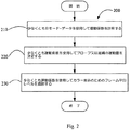
図2は、本発明の特定の実施形態に従ってカラーフロー・イメージングを実行するように構成されている(図1に示されたものと同様な)超音波機械又は機器において適応型フレーム平均化を実行するための方法200を示す高レベルの流れ図である。この方法200の少なくとも1つの実施形態では、段階210において、少なくともBモード・データ(例えば、1つのBモード画像フレーム)を使用して運動係数を計算することを含む。段階220において、少なくとも運動係数を使用して(プローブ又は組織の)運動量を決定することを含む。段階230において、少なくとも運動係数を使用してカラー表示のフレーム平均化レベルを調節することを含む。
FIG. 2 performs adaptive frame averaging in an ultrasound machine or instrument (similar to that shown in FIG. 1) configured to perform color flow imaging in accordance with certain embodiments of the invention. 3 is a high level flow diagram illustrating a
本発明の少なくとも1つの実施形態では、運動によって生じたカラーの遅延及びスミアリング・エイリアスを克服するために、カラーフロー画像のための運動適応型フレーム平均化を使用することができる。図3は、本発明の特定の実施形態に従ってカラーフロー・イメージングを実行するように構成されている(図1に示されたものと同様な)超音波機械又は機器においてこのような運動適応型フレーム平均化を実行するための方法300を示す流れ図である。一実施形態では、このようなフレーム平均化を実行するためのアルゴリズム又は方程式を使用することができる。
In at least one embodiment of the present invention, motion adaptive frame averaging for color flow images can be used to overcome color delays and smearing aliases caused by motion. FIG. 3 illustrates such a motion adaptive frame in an ultrasound machine or device (similar to that shown in FIG. 1) configured to perform color flow imaging in accordance with a particular embodiment of the present invention. FIG. 6 is a flow diagram illustrating a
方法300の少なくとも1つの実施形態では、段階310において、少なくとも1つの現在のBモード・フレームを少なくとも1つの以前のBモード・フレームと比較することによって、Bモード画像フレームから運動係数を計算することを含む。少なくとも1つの実施形態では、現在のBモード・フレームが(例えば、方程式を使用して)2つ以上の以前のBモード・フレームと比較される。
In at least one embodiment of the
段階320において、少なくとも運動係数を使用してプローブ及び/又は組織の運動量を決定することを含む。少なくとも1つの実施形態では、運動係数は現在のフレームと1つ以上の以前のフレームとの間のBモード・グレースケール画像の変化を決定又は測定すると考えられる。このような変化は、プローブ又は組織の動きの良好な推定値である。特に、運動係数はカラーフローの関心のある領域(これは「ROI」とも称される)から計算することができる。 Step 320 includes determining the amount of motion of the probe and / or tissue using at least the coefficient of motion. In at least one embodiment, the coefficient of motion is believed to determine or measure a change in B-mode grayscale image between the current frame and one or more previous frames. Such a change is a good estimate of probe or tissue movement. In particular, the coefficient of motion can be calculated from the region of interest of the color flow (also referred to as “ROI”).
少なくとも1つの実施形態では、この運動係数はカラー表示のためにフレーム平均レベルを調節するために使用することができる。段階330において、調節が必要であるかどうか判定することを含む。例示した実施形態では、このような調節の判定は少なくとも1つの閾値に関してなされる。より詳しく述べると、少なくとも1つの実施形態では、このような調節は、運動係数が少なくとも1つの所定の閾値よりも大きいか又は小さいかを判定することによって、行うことができる。段階340において、少なくとも部分的に、このような判定に基づいてフレーム平均化を調節することを含む。少なくとも1つの実施形態では、このような調節は、フレーム平均化のレベルを増大させるか又は減少させること、或いはフレーム平均化のレベルを調節しないことを含むことができる。更に、少なくとも1つの実施形態では、運動係数が特定のレベルである場合(すなわち、運動係数が第1の所定の閾値とは異なる第2の所定の閾値以上である場合)、フレーム平均化を停止させるように、少なくとも1つの所定の閾値を設定することも考えられる。フレーム平均化の停止は、強い運動が存在するときに遅延及びスミアリングを除く。
In at least one embodiment, this coefficient of motion can be used to adjust the frame average level for color display. Step 330 includes determining whether an adjustment is necessary. In the illustrated embodiment, such adjustment determination is made with respect to at least one threshold. More specifically, in at least one embodiment, such adjustment can be made by determining whether the coefficient of motion is greater than or less than at least one predetermined threshold.
本発明の少なくとも1つの実施形態では、少なくとも運動によって生じたカラーの遅延及びスミアリング・エイリアスを克服するために、カラーフロー画像のための運動適応型フレーム平均化を使用することができる。図4は、本発明の特定の実施形態に従ってカラーフロー・イメージングを実行するように構成されている(図1に示されたものと同様な)超音波機械又は機器においてこのような運動適応型フレーム平均化を実行するための方法400を示す流れ図である。少なくとも1つの実施形態では、このようなフレーム平均化を実行するためのアルゴリズム又は方程式を使用することができる。
In at least one embodiment of the present invention, motion adaptive frame averaging for color flow images can be used to overcome at least color delay and smearing aliases caused by motion. FIG. 4 illustrates such a motion adaptive frame in an ultrasound machine or device (similar to that shown in FIG. 1) configured to perform color flow imaging in accordance with a particular embodiment of the present invention. 4 is a flow diagram illustrating a
方法400の少なくとも1つの実施形態では、段階410において、少なくとも1つの現在のBモード・フレームを少なくとも1つの以前のBモード・フレームと比較することによって、Bモード画像フレームから運動係数を計算することを含む。少なくとも1つの実施形態では、現在のBモード・フレームが(例えば、方程式を使用して)2つ以上の以前のBモード・フレームと比較される。
In at least one embodiment of the
段階420において、少なくとも運動係数を使用してプローブ及び/又は組織の運動量を決定することを含む。少なくとも1つの実施形態では、前に述べたように、運動係数は現在のフレームと1つ以上の以前のフレームとの間のBモード・グレースケール画像の変化を決定又は測定すると考えられる。このような変化は、前に述べたように、プローブや組織の動きの良好な推定値である。特に、運動係数はカラーフローのROIから計算することができる。 Step 420 includes determining the amount of motion of the probe and / or tissue using at least the coefficient of motion. In at least one embodiment, as previously stated, the coefficient of motion is believed to determine or measure the change in the B-mode grayscale image between the current frame and one or more previous frames. Such changes are good estimates of probe and tissue motion, as previously described. In particular, the coefficient of motion can be calculated from the color flow ROI.
運動係数はカラー表示のためにフレーム平均レベルを調節するために使用することができる。段階430において、運動係数が所定の閾値よりも大きいか又は小さいかを判定することを含む。より詳しく述べると、少なくとも1つの実施形態では、段階430において、運動係数が第1の所定の閾値(例えば、低閾値)よりも小さいかどうか判定することを含む。運動係数が第1の所定の閾値よりも小さい場合(すなわち、運動係数が小さい場合)、段階440において、フレーム平均化のレベルを増大させることを含む。
The coefficient of motion can be used to adjust the frame average level for color display. Step 430 includes determining whether the coefficient of motion is greater than or less than a predetermined threshold. More particularly, in at least one embodiment, in
運動係数が第1の所定の閾値よりも小さくない場合、段階450において、運動係数が第2の所定の閾値(例えば、高閾値)よりも大きいかどうか判定することを含む。運動係数が第2の所定の閾値よりも大きい場合(すなわち、運動係数が大きい場合)、段階460において、少なくともプローブ又は組織の運動によって惹起される遅延及びカラー・エイリアスを避けるために、フレーム平均化のレベルを減少させることを含む。少なくとも1つの実施形態では、運動係数が第2の閾値よりも大きくない場合、方法400では、フレーム平均化のレベルを変更又は改変しない(すなわち、フレーム平均化が同じレベルに維持される)ことを含む。
If the coefficient of motion is not less than a first predetermined threshold,
更に、少なくとも1つの実施形態では、運動係数が第2の所定の閾値よりも特定量だけ大きい場合(すなわち、運動係数が第2の所定の閾値よりも特定量以上大きい場合)、フレーム平均化を停止させるように、少なくとも1つ(両方でない場合)の所定の閾値を設定することが考えられる。フレーム平均化の停止は、強い運動が存在するときに遅延及びスミアリングを除くことができる。 Further, in at least one embodiment, if the motion coefficient is greater than the second predetermined threshold by a certain amount (ie, if the motion coefficient is greater than the second predetermined threshold by a certain amount), frame averaging is performed. It is conceivable to set at least one (if not both) predetermined thresholds to stop. Stopping frame averaging can eliminate delays and smearing when strong motion is present.
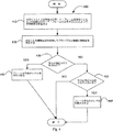
本発明の少なくとも1つの実施形態では、少なくとも運動によって生じるカラーの遅延及びスミアリング・エイリアスを克服するために、カラーフロー画像のための運動適応型フレーム平均化を使用することができる。図5は、例えば、本発明の特定の実施形態に従ってカラーフロー・イメージングを実行するように構成されている(図1に示されたものと同様な)超音波機械又は機器においてこのような運動適応型フレーム平均化を実行するための方法500を示す詳しい流れ図である。少なくとも1つの実施形態では、このようなフレーム平均化を実行するためのアルゴリズム又は方程式を使用することができる。
In at least one embodiment of the present invention, motion adaptive frame averaging for color flow images can be used to overcome at least color delay and smearing aliases caused by motion. FIG. 5 illustrates, for example, such motion adaptation in an ultrasound machine or instrument (similar to that shown in FIG. 1) configured to perform color flow imaging in accordance with a particular embodiment of the present invention. 5 is a detailed flowchart illustrating a
方法500の少なくとも1つの実施形態では、段階510において、少なくとも1つの現在のBモード・フレームを少なくとも1つの以前のBモード・フレームと比較することによって、Bモード画像フレームから運動係数を計算することを含む。少なくとも1つの実施形態では、現在のBモード・フレームが(例えば、方程式を使用して)2つ以上の以前のBモード・フレームと比較される。
In at least one embodiment of
段階520において、少なくとも運動係数を使用してプローブ及び/又は組織の運動量を決定することを含む。少なくとも1つの実施形態では、前に述べたように、運動係数は現在のフレームと1つ以上の以前のフレームとの間のBモード・グレースケール画像の変化を決定又は測定すると考えられる。特に、運動係数はカラーフローのROIから計算することができる。 Step 520 includes determining the amount of motion of the probe and / or tissue using at least the coefficient of motion. In at least one embodiment, as previously stated, the coefficient of motion is believed to determine or measure the change in the B-mode grayscale image between the current frame and one or more previous frames. In particular, the coefficient of motion can be calculated from the color flow ROI.
運動係数はカラー表示のためにフレーム平均レベルを調節するために使用することができる。段階530において、運動係数が所定の閾値よりも大きいか又は小さいかを判定することを含む。より詳しく述べると、少なくとも1つの実施形態では、段階530において、運動係数が第1の所定の閾値(例えば、高閾値)よりも大きいかどうか判定することを含む。運動係数が第1の閾値よりも大きい場合(すなわち、運動係数が大きい場合)、段階540において、フレーム平均化のレベルを減少させることを含む。
The coefficient of motion can be used to adjust the frame average level for color display. Step 530 includes determining whether the coefficient of motion is greater than or less than a predetermined threshold. More specifically, in at least one embodiment, at
運動係数が第1の所定の閾値よりも大きくない場合、段階550において、運動係数が第2の所定の閾値(例えば、低閾値)よりも小さいかどうか判定することを含む。運動係数が第2の所定の閾値よりも小さい場合(すなわち、運動係数が小さい場合)、段階560において、少なくともプローブ又は組織の運動によって惹起される遅延及びカラー・エイリアスを避けるために、フレーム平均化のレベルを増大させることを含む。少なくとも1つの実施形態では、運動係数が第2の閾値よりも大きくない場合、方法500では、フレーム平均化のレベルを変更又は改変しない(すなわち、フレーム平均化が同じレベルに維持される)ことを含む。
If the motion coefficient is not greater than the first predetermined threshold,
更に、少なくとも1つの実施形態では、運動係数が第1の所定の閾値よりも特定量だけ大きい場合(すなわち、運動係数が第1の所定の閾値よりも特定量以上大きい場合)、フレーム平均化を停止させるように、少なくとも1つ(両方でない場合)の所定の閾値を設定できることが考えられる。フレーム平均化の停止は、強い運動が存在するときに遅延及びスミアリングを除く。 Further, in at least one embodiment, if the motion coefficient is greater than the first predetermined threshold by a certain amount (ie, if the motion coefficient is greater than the first predetermined threshold by a certain amount), frame averaging is performed. It is conceivable that at least one (if not both) predetermined threshold can be set to stop. Stopping frame averaging eliminates delay and smearing when strong motion is present.
本発明の少なくとも1つの実施形態では、フレーム平均化の調節は、少なくとも部分的に、以下に規定するのと同様なフレーム平均化方程式に依存する。例えば、フレーム平均化が単純な算術平均演算として具現される場合、フレーム平均化のレベルの増大は或る数の以前のフレームとの算術平均を計算することによって具現することができる。少なくとも1つの実施形態では、FIR又はIIRのフレーム平均化レベルは、関連するフレームの数を調節する又は変更することであってよい。更に、FIR又はIIRのフレーム平均化レベルはまた、フィルタ係数を単独で、又はフレームの数を調節又は変更することと組み合わせて、変更又は調節することによって、調節又は修正することができると考えられる。 In at least one embodiment of the invention, the adjustment of frame averaging relies at least in part on a frame averaging equation similar to that defined below. For example, if frame averaging is implemented as a simple arithmetic average operation, an increase in the level of frame averaging can be implemented by calculating an arithmetic average with a certain number of previous frames. In at least one embodiment, the FIR or IIR frame averaging level may be to adjust or change the number of associated frames. In addition, the FIR or IIR frame averaging level could also be adjusted or modified by changing or adjusting the filter coefficients alone or in combination with adjusting or changing the number of frames. .
少なくとも1つの実施形態では、方程式は運動に敏感で、運動に応答し、Bモード・フレーム速度が通常約10〜約20Hzであるので約1/10〜約1/20秒の応答時間を持つと考えられる。運動係数はスキャナのシステム・メモリに記憶することができる。一実施形態では、運動係数は別個の単独のメモリに、或いはシステム又は機器5の構成部品(例えば、プロセッサ50)の中に又はその上に記憶することができる。 In at least one embodiment, the equation is motion sensitive and responsive to motion, and has a response time of about 1/10 to about 1/20 second because the B-mode frame rate is typically about 10 to about 20 Hz. Conceivable. The coefficient of motion can be stored in the system memory of the scanner. In one embodiment, the coefficient of motion may be stored in a separate single memory, or in or on a component of system or device 5 (eg, processor 50).
一実施形態では、記憶された運動はBモード表示サブシステムを使用して更新されると共に、カラー表示サブシステムによって読み出される。Bモード及びカラー表示サブシステムは、前に述べたものと同様な超音波システム又は機器5の部分であるハードウエア部品、或いはシステム5上で(例えば、プロセッサ50上で)実行するソフトウエアであってよいと考えられる。 In one embodiment, the stored motion is updated using the B-mode display subsystem and is read by the color display subsystem. The B-mode and color display subsystem is a hardware component that is part of an ultrasound system or device 5 similar to that previously described, or software that runs on the system 5 (eg, on the processor 50). It is considered good.
少なくとも1つの実施形態では、Bモード表示が一般的に組織又はプローブの動きによってのみ変化することを理解されたい。従って、運動係数を計算するためにBモード・データを使用することは、プローブ及び/又は組織の真の運動の良好な推定値を与える。しかしながら、運動係数を計算するために他の方法を使用してもよい。本発明の一実施形態では、カラー・フレーム・データを使用して運動係数を計算することを含む。 It should be understood that in at least one embodiment, the B-mode display generally changes only with tissue or probe movement. Thus, using B-mode data to calculate the coefficient of motion provides a good estimate of the true motion of the probe and / or tissue. However, other methods may be used to calculate the coefficient of motion. One embodiment of the invention includes calculating the coefficient of motion using color frame data.
本発明の少なくとも1つの実施形態では、運動係数は少なくとも1つのBモード・フレーム、より具体的には少なくとも2つのBモード・フレームを使用して計算することができる。本発明の少なくとも1つの実施形態では、絶対差(「SAD」とも称される)の和を計算するために次の方程式が使用される。 In at least one embodiment of the present invention, the coefficient of motion can be calculated using at least one B-mode frame, more specifically at least two B-mode frames. In at least one embodiment of the invention, the following equation is used to calculate the sum of absolute differences (also referred to as “SAD”):
M=(Σ|Xi−Xi−1|)/(Σ|Xi|)
ここで、Xi ,Xi−1 は現在のBモード・フレーム及び以前のBモード・フレームのグレースケール画素値である。
M = (Σ | X i −X i−1 |) / (Σ | X i |)
Here, X i and X i−1 are gray scale pixel values of the current B-mode frame and the previous B-mode frame.
この方程式は運動係数を計算するために使用することができ、運動係数はプローブ又は組織の運動によって惹起されるカラー遅延及びスミアリングを低減及び/又は除去するために使用することができる。この方程式を使用して計算された運動係数は、一実施形態ではこの運動係数がBモード・データの各々のフレームについて計算されるので、速い応答速度を持ち、且つ運動に対し敏感である。ここで、Bモード・フレーム速度は約10〜約20Hzである。従って、突発的な運動に対する応答時間は約1/20〜約1/10秒である。何ら運動が検出されないとき、方程式は自動的にフレーム平均のためのレベルを増大させ、従って、SNR及びカラー持続性を更に増大させる。 This equation can be used to calculate the coefficient of motion, which can be used to reduce and / or eliminate color delay and smearing caused by probe or tissue motion. The coefficient of motion calculated using this equation has a fast response speed and is sensitive to motion because in one embodiment this coefficient of motion is calculated for each frame of B-mode data. Here, the B-mode frame rate is about 10 to about 20 Hz. Accordingly, the response time for sudden movement is about 1/20 to about 1/10 seconds. When no motion is detected, the equation automatically increases the level for frame averaging, thus further increasing SNR and color persistence.
運動係数を決定するために方程式を使用することはまた、運動係数についてのこのような計算が実時間で実施するのに簡単且つ容易であるので、効率がよいことを理解されたい。この方程式は、運動によるBモード画像のぼやけを低減するために使用することができ、従って、運動係数は、一実施形態では、各Bモード・フレームについて一度だけ計算して、カラー及びBモード・フレーム平均の両方について用いることができる。 It should be understood that using an equation to determine the coefficient of motion is also efficient because such calculations for the coefficient of motion are simple and easy to perform in real time. This equation can be used to reduce blurring of B-mode images due to motion, so the motion coefficient is calculated only once for each B-mode frame in one embodiment, and color and B-mode It can be used for both frame averaging.
本発明を様々な特定の実施形態について説明したが、当業者には、本発明の範囲から逸脱することなく様々な変更を為し且つ等価物と置換することができることが理解されよう。更に、特定の状況及び物質を本発明の範囲から逸脱することなく本発明の教示に適合させるように多くの修正を行うことができる。従って、本発明は開示した特定の実施形態に限定されるのではなく、特許請求の範囲内に入る全ての実施形態を含むものである。 While the invention has been described in terms of various specific embodiments, those skilled in the art will recognize that various modifications and equivalents can be made without departing from the scope of the invention. In addition, many modifications may be made to adapt a particular situation and material to the teachings of the invention without departing from the scope of the invention. Accordingly, the invention is not limited to the specific embodiments disclosed, but includes all embodiments that fall within the scope of the claims.
5 超音波機械
15 アナログ・インターフェース
66 心臓タイミング事象信号
70 母線
200、300、400、500 フレーム平均化を実行するための方法
5
Claims (10)
少なくともBモード・データを使用して運動係数を計算する段階と、
少なくとも前記運動係数を使用して運動量を決定する段階であって、前記運動係数が前記運動量の推定値を表す、前記段階と、
前記運動係数を第1及び第2の閾値と比較することにより少なくとも前記運動係数を使用してフレーム平均化を調節する段階と、
を有し、
前記運動係数が前記第1の閾値よりも小さい場合には前記フレーム平均化に含まれるフレームの数を増加させ、
前記運動係数が前記第2の閾値よりも大きい場合には前記フレーム平均化に含まれるフレームの数を減少させ、
前記運動係数が前記第2の閾値よりも特定量以上大きい場合には前記フレーム平均化を停止させ、
前記第2の閾値が前記第1の閾値よりも大きい、方法。A method for performing frame averaging of color flow frames in a device that generates at least one color flow image, comprising:
Calculating a coefficient of motion using at least B-mode data;
Determining a momentum using at least the motion coefficient , wherein the motion coefficient represents an estimate of the momentum ;
Adjusting frame averaging using at least the motion coefficient by comparing the motion coefficient with first and second thresholds ;
Have,
Increasing the number of frames included in the frame averaging if the coefficient of motion is less than the first threshold;
If the motion coefficient is greater than the second threshold, reduce the number of frames included in the frame averaging;
If the motion coefficient is greater than the second threshold by a specific amount or more, stop the frame averaging,
The method wherein the second threshold is greater than the first threshold .
少なくとも1つの現在のBモード・フレームを少なくとも1つの以前のBモード・フレームとを比較することによって運動係数を計算する段階と、
少なくとも前記運動係数を使用して運動量を決定する段階であって、前記運動係数が前記運動量の推定値を表す、前記段階と、
前記運動係数が第1の所定の閾値よりも小さい場合、フレーム平均化に含まれるフレームの数を増大させる段階と、
前記運動係数が前記第1の所定の閾値よりも大きい場合、フレーム平均化に含まれるフレームの数を減少させる段階と、
前記運動係数が前記第2の閾値よりも特定量以上大きい場合には前記フレーム平均化を停止させる段階と、を有し、
前記第2の所定の閾値が前記第1の所定の閾値よりも大きい、方法。A method for performing frame averaging of a color flow frame in an ultrasound instrument performing color flow imaging, comprising:
Calculating a coefficient of motion by comparing at least one current B-mode frame with at least one previous B-mode frame;
Determining a momentum using at least the motion coefficient , wherein the motion coefficient represents an estimate of the momentum ;
If the coefficient of motion is less than a first predetermined threshold, increasing the number of frames included in the frame averaging;
Reducing the number of frames included in frame averaging if the motion coefficient is greater than the first predetermined threshold;
Stopping the frame averaging when the coefficient of motion is greater than the second threshold by a specific amount ,
The method wherein the second predetermined threshold is greater than the first predetermined threshold .
動いている組織の中へ超音波を送り込んで、前記動いている組織から後方散乱された超音波に応答して受信信号を発生するように配置構成されているフロントエンドと、
受信信号に応答して、少なくとも1つの現在のBモード・フレームを少なくとも1つの以前のBモード・フレームと比較することによって運動係数を計算し、前記運動係数が所定の閾値よりも小さい場合はフレーム平均化に含まれるフレームの数を増大させ、また前記運動係数が前記所定の閾値よりも大きい場合は前記フレーム平均化に含まれるフレームの数を減少させ、前記運動係数が前記第2の所定の閾値よりも特定量以上大きい場合には前記フレーム平均化を停止させる少なくとも1つのプロセッサと、
を有しており、
前記第2の所定の閾値が前記第1の所定の閾値よりも大きく、
前記運動係数が前記運動量の推定値を表している超音波装置。An ultrasound device that performs frame averaging of color flow frames in response to moving tissue and generates color flow imaging,
A front end configured to send ultrasonic waves into moving tissue and generate a received signal in response to ultrasonic waves backscattered from the moving tissue;
In response to the received signal, calculate a motion coefficient by comparing at least one current B-mode frame with at least one previous B-mode frame, and a frame if the motion coefficient is less than a predetermined threshold Increasing the number of frames included in the averaging, and decreasing the number of frames included in the frame averaging if the motion coefficient is greater than the predetermined threshold ; at least one processor that is stopped the frame averaging is larger than a specific amount than the threshold value,
A has,
The second predetermined threshold is greater than the first predetermined threshold;
An ultrasonic apparatus in which the motion coefficient represents an estimated value of the momentum .
Applications Claiming Priority (3)
| Application Number | Priority Date | Filing Date | Title |
|---|---|---|---|
| US50137503P | 2003-09-09 | 2003-09-09 | |
| US60/501,375 | 2003-09-09 | ||
| PCT/US2004/029609 WO2005023098A2 (en) | 2003-09-09 | 2004-09-09 | Motion adaptive frame averaging for ultrasound doppler color flow imaging |
Publications (3)
| Publication Number | Publication Date |
|---|---|
| JP2007504862A JP2007504862A (en) | 2007-03-08 |
| JP2007504862A5 JP2007504862A5 (en) | 2007-10-25 |
| JP4729491B2 true JP4729491B2 (en) | 2011-07-20 |
Family
ID=34273037
Family Applications (1)
| Application Number | Title | Priority Date | Filing Date |
|---|---|---|---|
| JP2006525549A Active JP4729491B2 (en) | 2003-09-09 | 2004-09-09 | Motion adaptive frame averaging for ultrasound Doppler color flow imaging |
Country Status (3)
| Country | Link |
|---|---|
| US (1) | US7153268B2 (en) |
| JP (1) | JP4729491B2 (en) |
| WO (1) | WO2005023098A2 (en) |
Families Citing this family (20)
| Publication number | Priority date | Publication date | Assignee | Title |
|---|---|---|---|---|
| US7101336B2 (en) * | 2003-11-25 | 2006-09-05 | General Electric Company | Methods and systems for motion adaptive spatial compounding |
| DE102005006287A1 (en) * | 2005-02-11 | 2006-08-17 | Bayerische Motoren Werke Ag | Method and device for monitoring the environment of a vehicle |
| US7474727B2 (en) * | 2005-10-14 | 2009-01-06 | Siemens Aktiengesellschaft | Dynamic computed tomography method and apparatus with temporal interpolation of data in perfusion studies |
| US20090105580A1 (en) * | 2005-11-29 | 2009-04-23 | Eirik Nestaas | Choosing variables in tissue velocity imaging |
| US7471767B2 (en) * | 2006-05-03 | 2008-12-30 | Siemens Medical Solutions Usa, Inc. | Systems and methods for determining image acquisition parameters |
| WO2008101684A1 (en) | 2007-02-21 | 2008-08-28 | Universität Duisburg Essen | Method and device for the ultrasonography of blood flow |
| WO2009026534A1 (en) | 2007-08-23 | 2009-02-26 | Verasonics, Inc. | Adaptive ultrasound image reconstruction based on sensing of local media motion |
| JP5219609B2 (en) * | 2008-05-01 | 2013-06-26 | キヤノン株式会社 | Frame rate conversion apparatus, method and program |
| JP5219608B2 (en) * | 2008-05-01 | 2013-06-26 | キヤノン株式会社 | Frame rate conversion apparatus, method and program |
| US20100305438A1 (en) * | 2009-05-29 | 2010-12-02 | Kenneth Wayne Rigby | System and method for scaling strain image data |
| JP5652395B2 (en) * | 2009-09-28 | 2015-01-14 | コニカミノルタ株式会社 | Ultrasonic diagnostic equipment |
| US8696579B2 (en) | 2010-06-04 | 2014-04-15 | Siemens Medical Solutions Usa, Inc. | Cardiac flow quantification with volumetric imaging data |
| JP2013188236A (en) * | 2010-07-05 | 2013-09-26 | Konica Minolta Medical & Graphic Inc | Ultrasonic diagnostic apparatus and program |
| KR101232021B1 (en) * | 2010-11-29 | 2013-02-08 | 삼성메디슨 주식회사 | Ultrasound system and method for processing frame average based on motion estimation |
| KR101313221B1 (en) | 2010-11-29 | 2013-10-14 | 삼성메디슨 주식회사 | Ultrasound system and method for processing adaptive frame average |
| US20120203093A1 (en) * | 2011-02-08 | 2012-08-09 | Mir Imran | Apparatus, system and methods for photoacoustic detection of deep vein thrombosis |
| US9420997B2 (en) | 2012-06-14 | 2016-08-23 | Siemens Medical Solutions Usa, Inc. | Motion artifact suppression in ultrasound diagnostic imaging |
| JP6406019B2 (en) * | 2015-01-09 | 2018-10-17 | コニカミノルタ株式会社 | Ultrasonic signal processing apparatus and ultrasonic diagnostic apparatus |
| DE102016219391A1 (en) * | 2016-10-06 | 2018-04-12 | Robert Bosch Gmbh | Method for noise optimization of a camera, in particular a hand-held thermal imaging camera |
| JP7343342B2 (en) | 2019-09-25 | 2023-09-12 | キヤノンメディカルシステムズ株式会社 | Ultrasonic diagnostic equipment and image processing equipment |
Citations (4)
| Publication number | Priority date | Publication date | Assignee | Title |
|---|---|---|---|---|
| JPH05168626A (en) * | 1991-12-26 | 1993-07-02 | Aloka Co Ltd | Ultrasonic diagnostic system |
| JPH09220228A (en) * | 1996-02-19 | 1997-08-26 | Ge Yokogawa Medical Syst Ltd | Blood flow information image display method and ultrasonic diagnostic system |
| JPH11313822A (en) * | 1998-03-20 | 1999-11-16 | General Electric Co <Ge> | Three-dimensional imaging system, and method and device for following movement of scanning plane |
| JP2001521404A (en) * | 1996-02-29 | 2001-11-06 | アキューソン コーポレイション | Multiple ultrasound image registration system, method and transducer |
Family Cites Families (5)
| Publication number | Priority date | Publication date | Assignee | Title |
|---|---|---|---|---|
| US5622174A (en) * | 1992-10-02 | 1997-04-22 | Kabushiki Kaisha Toshiba | Ultrasonic diagnosis apparatus and image displaying system |
| JP3732613B2 (en) * | 1997-04-15 | 2006-01-05 | フクダ電子株式会社 | Ultrasonic diagnostic equipment |
| US6511426B1 (en) * | 1998-06-02 | 2003-01-28 | Acuson Corporation | Medical diagnostic ultrasound system and method for versatile processing |
| US6364835B1 (en) * | 1998-11-20 | 2002-04-02 | Acuson Corporation | Medical diagnostic ultrasound imaging methods for extended field of view |
| US6484049B1 (en) | 2000-04-28 | 2002-11-19 | Ge Medical Systems Global Technology Company, Llc | Fluoroscopic tracking and visualization system |
-
2004
- 2004-09-09 JP JP2006525549A patent/JP4729491B2/en active Active
- 2004-09-09 WO PCT/US2004/029609 patent/WO2005023098A2/en active Application Filing
- 2004-09-09 US US10/937,529 patent/US7153268B2/en active Active
Patent Citations (4)
| Publication number | Priority date | Publication date | Assignee | Title |
|---|---|---|---|---|
| JPH05168626A (en) * | 1991-12-26 | 1993-07-02 | Aloka Co Ltd | Ultrasonic diagnostic system |
| JPH09220228A (en) * | 1996-02-19 | 1997-08-26 | Ge Yokogawa Medical Syst Ltd | Blood flow information image display method and ultrasonic diagnostic system |
| JP2001521404A (en) * | 1996-02-29 | 2001-11-06 | アキューソン コーポレイション | Multiple ultrasound image registration system, method and transducer |
| JPH11313822A (en) * | 1998-03-20 | 1999-11-16 | General Electric Co <Ge> | Three-dimensional imaging system, and method and device for following movement of scanning plane |
Also Published As
| Publication number | Publication date |
|---|---|
| US20050075569A1 (en) | 2005-04-07 |
| JP2007504862A (en) | 2007-03-08 |
| WO2005023098A3 (en) | 2006-04-13 |
| WO2005023098A2 (en) | 2005-03-17 |
| US7153268B2 (en) | 2006-12-26 |
Similar Documents
| Publication | Publication Date | Title |
|---|---|---|
| JP4729491B2 (en) | Motion adaptive frame averaging for ultrasound Doppler color flow imaging | |
| JP4722283B2 (en) | Method and apparatus for motion visualization in ultrasonic flow imaging using continuous data acquisition | |
| US8523776B2 (en) | Ultrasonic doppler imaging apparatus and method with blood velocity waveform processing | |
| JP5054361B2 (en) | Automatic adjustment of spectral Doppler gain in ultrasound systems | |
| US11000263B2 (en) | Ultrasound diagnostic apparatus, image processing device, and image processing method | |
| JP4627366B2 (en) | Method and apparatus for motion visualization in ultrasonic flow imaging using packet data acquisition | |
| JP5652395B2 (en) | Ultrasonic diagnostic equipment | |
| US11123044B2 (en) | Signal processing device, ultrasonic diagnostic apparatus, and method | |
| US20150359507A1 (en) | Ultrasound diagnosis apparatus and ultrasound image processing method | |
| JP2001299764A (en) | Ultrasonographic instrument | |
| JP3410821B2 (en) | Ultrasound diagnostic equipment | |
| WO2020083679A1 (en) | Adaptive ultrasound flow imaging | |
| US20090105593A1 (en) | Frame averaging circuit for use in an ultrasound imaging system | |
| EP3136974B1 (en) | Elastography visualization | |
| JP4808373B2 (en) | Method and apparatus for applications related to B-mode image banding suppression | |
| WO2006088094A1 (en) | Ultrasonic doppler rheometer | |
| JP4481386B2 (en) | Ultrasonic diagnostic equipment | |
| JP5455567B2 (en) | Ultrasonic diagnostic equipment | |
| JP4067914B2 (en) | Ultrasonic diagnostic equipment | |
| JP7343342B2 (en) | Ultrasonic diagnostic equipment and image processing equipment | |
| JPH08322841A (en) | Ultrasonic doppler rheometer | |
| JP6536357B2 (en) | Ultrasound imaging system | |
| JP2002034984A (en) | Flow information data average processing method, and ultrasonograph | |
| JP2024034087A (en) | Ultrasound diagnostic device and blood flow image data generation method | |
| JP2003180693A (en) | Ultrasonic diagnosis device |
Legal Events
| Date | Code | Title | Description |
|---|---|---|---|
| A521 | Written amendment |
Free format text: JAPANESE INTERMEDIATE CODE: A523 Effective date: 20070904 |
|
| A621 | Written request for application examination |
Free format text: JAPANESE INTERMEDIATE CODE: A621 Effective date: 20070904 |
|
| A131 | Notification of reasons for refusal |
Free format text: JAPANESE INTERMEDIATE CODE: A131 Effective date: 20101005 |
|
| A601 | Written request for extension of time |
Free format text: JAPANESE INTERMEDIATE CODE: A601 Effective date: 20101228 |
|
| RD02 | Notification of acceptance of power of attorney |
Free format text: JAPANESE INTERMEDIATE CODE: A7422 Effective date: 20101228 |
|
| RD04 | Notification of resignation of power of attorney |
Free format text: JAPANESE INTERMEDIATE CODE: A7424 Effective date: 20101228 |
|
| A602 | Written permission of extension of time |
Free format text: JAPANESE INTERMEDIATE CODE: A602 Effective date: 20110111 |
|
| A521 | Written amendment |
Free format text: JAPANESE INTERMEDIATE CODE: A523 Effective date: 20110302 |
|
| A01 | Written decision to grant a patent or to grant a registration (utility model) |
Free format text: JAPANESE INTERMEDIATE CODE: A01 Effective date: 20110329 |
|
| A61 | First payment of annual fees (during grant procedure) |
Free format text: JAPANESE INTERMEDIATE CODE: A61 Effective date: 20110418 |
|
| R150 | Certificate of patent or registration of utility model |
Free format text: JAPANESE INTERMEDIATE CODE: R150 |
|
| FPAY | Renewal fee payment (event date is renewal date of database) |
Free format text: PAYMENT UNTIL: 20140422 Year of fee payment: 3 |
|
| R250 | Receipt of annual fees |
Free format text: JAPANESE INTERMEDIATE CODE: R250 |
|
| R250 | Receipt of annual fees |
Free format text: JAPANESE INTERMEDIATE CODE: R250 |
|
| R250 | Receipt of annual fees |
Free format text: JAPANESE INTERMEDIATE CODE: R250 |
|
| R250 | Receipt of annual fees |
Free format text: JAPANESE INTERMEDIATE CODE: R250 |
|
| R250 | Receipt of annual fees |
Free format text: JAPANESE INTERMEDIATE CODE: R250 |
|
| R250 | Receipt of annual fees |
Free format text: JAPANESE INTERMEDIATE CODE: R250 |