JP4235456B2 - Encoder operation - Google Patents
Encoder operation Download PDFInfo
- Publication number
- JP4235456B2 JP4235456B2 JP2002591922A JP2002591922A JP4235456B2 JP 4235456 B2 JP4235456 B2 JP 4235456B2 JP 2002591922 A JP2002591922 A JP 2002591922A JP 2002591922 A JP2002591922 A JP 2002591922A JP 4235456 B2 JP4235456 B2 JP 4235456B2
- Authority
- JP
- Japan
- Prior art keywords
- signal
- clock
- data
- evaluation unit
- encoder
- Prior art date
- Legal status (The legal status is an assumption and is not a legal conclusion. Google has not performed a legal analysis and makes no representation as to the accuracy of the status listed.)
- Expired - Fee Related
Links
Images

Classifications
-
- H—ELECTRICITY
- H04—ELECTRIC COMMUNICATION TECHNIQUE
- H04L—TRANSMISSION OF DIGITAL INFORMATION, e.g. TELEGRAPHIC COMMUNICATION
- H04L7/00—Arrangements for synchronising receiver with transmitter
- H04L7/0008—Synchronisation information channels, e.g. clock distribution lines
-
- G—PHYSICS
- G01—MEASURING; TESTING
- G01D—MEASURING NOT SPECIALLY ADAPTED FOR A SPECIFIC VARIABLE; ARRANGEMENTS FOR MEASURING TWO OR MORE VARIABLES NOT COVERED IN A SINGLE OTHER SUBCLASS; TARIFF METERING APPARATUS; MEASURING OR TESTING NOT OTHERWISE PROVIDED FOR
- G01D5/00—Mechanical means for transferring the output of a sensing member; Means for converting the output of a sensing member to another variable where the form or nature of the sensing member does not constrain the means for converting; Transducers not specially adapted for a specific variable
- G01D5/12—Mechanical means for transferring the output of a sensing member; Means for converting the output of a sensing member to another variable where the form or nature of the sensing member does not constrain the means for converting; Transducers not specially adapted for a specific variable using electric or magnetic means
- G01D5/244—Mechanical means for transferring the output of a sensing member; Means for converting the output of a sensing member to another variable where the form or nature of the sensing member does not constrain the means for converting; Transducers not specially adapted for a specific variable using electric or magnetic means influencing characteristics of pulses or pulse trains; generating pulses or pulse trains
- G01D5/24457—Failure detection
Abstract
Description
本発明は、エンコーダの作動方法に関する。 The present invention relates to a method for operating an encoder.
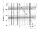
位置データをエンコーダから直列接続された評価ユニット又は順次電子機器にシリアル伝送する方法が、ヨーロッパ特許発明第660 209 号明細書から公知である。この場合、データ線上の双方向のデータ伝送は、1つのクロック信号によってパラレルクロック伝送線上の特定の伝送クロック周波数に同期される。位置データ及び場合によってはその他のデータがこのようにして増大すると共に、伝送速度又は伝送すべきデータ量に関する要求も高まる。伝送速度に加えてエンコーダと評価ユニットとの間の伝送区間がさらに拡張した場合、データ線上の伝送されるデータの信号経過時間が最終的にかなり長くなる。こうして発生する遅延時間は、いろいろなデータを正しく再処理するために考慮しなくてはならない。いろいろなデータを正しく再処理することを保証するため、データ線上で伝送されるデータビットを、評価ユニット側でクロック信号のクロックエッジに対して一義的に常に割り当てなくてはならないことが、これに対する理由である。したがって新たな措置を講じないと、最大許容伝送距離又はケーブル長さ及び最大許容伝送速度又は伝送クロック周波数が明らかに制限される。最大許容伝送クロック周波数fC とケーブル長さLK との間の関係が、図3中に具体的に示されている。例えばケーブル長さが100mの場合、最大許容伝送クロック周波数はfC =500kHz にすぎないことがこのグラフから分かる。 A method for serial transmission of position data from an encoder to serially connected evaluation units or sequentially to electronic devices is known from EP 660 209. In this case, bidirectional data transmission on the data line is synchronized to a specific transmission clock frequency on the parallel clock transmission line by one clock signal. As the position data and possibly other data increase in this way, the requirements on the transmission rate or the amount of data to be transmitted also increase. If the transmission section between the encoder and the evaluation unit is further expanded in addition to the transmission speed, the signal elapsed time of the data transmitted on the data line will eventually become considerably long. The delay time thus generated must be taken into account in order to correctly reprocess various data. In order to guarantee correct reprocessing of various data, the data bit transmitted on the data line must always be uniquely assigned to the clock edge of the clock signal on the evaluation unit side. That is why. Thus, unless new measures are taken, the maximum allowable transmission distance or cable length and the maximum allowable transmission speed or transmission clock frequency are clearly limited. The relationship between the maximum allowable transmission clock frequency f C and the cable length L K is specifically shown in FIG. For example, it can be seen from this graph that when the cable length is 100 m, the maximum allowable transmission clock frequency is only f C = 500 kHz.
本発明の課題は、長い伝送距離にわたっても高い伝送速度によってシリアル方式のデータをエンコーダと直列接続された評価ユニットとの間で伝送することを可能にするエンコーダの作動方法を提供することにある。 An object of the present invention is to provide a method of operating an encoder that enables serial data to be transmitted between an encoder and an evaluation unit connected in series at a high transmission speed over a long transmission distance.
この課題は、請求項1の特徴を備えた方法によって解決される。
This problem is solved by a method with the features of
この発明の方法の好適な実施形は、請求項1の従属請求項中に説明されている手段から得られる。
Preferred embodiments of the method according to the invention are obtained from the means described in the dependent claims of
この発明の方法を実施するために適したエンコーダは、請求項14に記載されている。 An encoder suitable for carrying out the method of the invention is described in claim 14 .
本発明によれば、エンコーダ,伝送区間及び評価ユニットから成るその都度の構成に固有の信号所要時間が、実際の測定動作の前に算出される。引き続き、こうして算出された信号所要時間は、位置データ及び場合によってはさらなるデータの再処理時に適切に使用される。すなわち、本発明にしたがって算出された信号所要時間を適用することによって、データ線上で伝送される二進データ語とクロック線上のクロック信号のクロックエッジとの間の正確な同期が実行できる。より長い伝送区間にわたっても高い伝送速度でデータをエンコーダと評価ユニットとの間で確実に伝送可能であることが、最終的にこの方法で保証され得る。例えば、データが、100 mにわたって4MHz以上の伝送クロック周波数で伝送され得る。これは、従来の技術に比べて8倍程度の伝送クロック周波数である。 According to the present invention, the signal required time specific to each configuration comprising an encoder, a transmission section and an evaluation unit is calculated before the actual measurement operation. Subsequently, the signal duration calculated in this way is appropriately used when reprocessing the position data and possibly further data. That is, by applying the signal required time calculated according to the present invention, accurate synchronization between the binary data word transmitted on the data line and the clock edge of the clock signal on the clock line can be performed. It can finally be ensured in this way that data can be reliably transmitted between the encoder and the evaluation unit at a high transmission rate over a longer transmission interval. For example, data may be transmitted at a transmission clock frequency of 4 MHz or higher over 100 m. This is a transmission clock frequency about eight times that of the prior art.
特に、信号所要時間が何回も算出される。その結果、信号所要時間が確実に算定される。そのため、不正確な値が、データ伝送区間上の場合によっては起こり得る一時的なノイズによって算出されない。 In particular, the signal required time is calculated many times. As a result, the required signal time is reliably calculated. Therefore, an inaccurate value is not calculated due to temporary noise that may occur in some cases on the data transmission interval.
本発明の方法は基本的にはエンコーダ,データ伝送区間及び評価ユニットから成る構成の変更ごとに並びに/又はエンコーダ及び/若しくは評価ユニットの給電の中断ごとに新たに実施されることが特に有益であることが実証されている。特にこの場合、信号所要時間の新たな算出が自動的に実行される。 It is particularly advantageous that the method according to the invention is carried out anew every time a configuration change consisting essentially of an encoder, a data transmission section and an evaluation unit and / or every interruption of the power supply of the encoder and / or evaluation unit. It has been proven. Particularly in this case, a new calculation of the required signal time is automatically executed.
以下に、本発明のその他の利点及び詳細を添付した図面に基づく実施の形態から説明する。 In the following, other advantages and details of the present invention will be described from an embodiment based on the attached drawings.
図1中には、概略的なブロック図が示されている。このブロック図は、エンコーダ10と直列接続された評価ユニット20とから構成されたシステムの基本的な構成を具体的に示す。このエンコーダ10とこの評価ユニット20とは、異なる信号線30.1,30.2,31.1,31.2を通じて伝送区間に沿って互いに接続されている。具体的な用途では、エンコーダ10が、例えば電動機ハウジング40内に配置されていて、電動機の横側で電動機の回転子の相対位置及び/又は絶対位置に関する位置データを記録する。この目的に対して、例えば回転割出し板上に配置された測定目盛を光電式に走査してもよい。この場合、位相のずれた走査信号が、インクリメンタル信号の形態で生成される。これらのインクリメンタル信号は、エンコーダ10側で絶対位置データに再処理され、適切に評価してデータ線31.1,31.2を通じて評価ユニット20に2進データ語としてシリアル式に伝送される。評価ユニット20又は順次電子機器の場合、この評価ユニット20又はこの順次電子機器は、例えば電動機の制御を伝送されるデータに基づいて請け負う通常の電動機の制御部又は電動機の調整部である。
A schematic block diagram is shown in FIG. This block diagram specifically shows a basic configuration of a system including an
このような用途とは別に、例えば加工すべき加工品に対する工具の精確な位置を測定し、対応する位置データを再処理のために工作機械の数値制御部として構成された評価ユニットに伝送するため、エンコーダを工作機械内で使用してもよい。例えば測長器,シャフトエンコーダ又は測角器が、エンコーダとして使用され得る。 Apart from such applications, for example, to measure the exact position of the tool with respect to the work piece to be machined, and to transmit the corresponding position data to an evaluation unit configured as a numerical controller of the machine tool for reprocessing. The encoder may be used in a machine tool. For example, a length measuring device, a shaft encoder or a goniometer can be used as the encoder.
さらに本発明は、位置データを物理的に生成する上述した方法に明らかに限定されない。別の走査原理に基づくエンコーダを稼働させることも可能である。 Furthermore, the present invention is clearly not limited to the above-described method of physically generating position data. It is also possible to operate an encoder based on another scanning principle.
エンコーダ10と直列接続された評価ユニットとの間のデータ伝送の方法は、ヨーロッパ特許発明第 660 209号明細書から公知の双方向同期シリアルデータ伝送にほぼ一致する;この双方向同期シリアルデータ伝送は、さらにいわゆる EnDat-Interfaceとしても関連して公知である。
The method of data transmission between the
データを実際に伝送するため、データ線31.1,31.2及びクロック線30.1,30.2が、データ伝送に必要なトランシーバー構成要素に接続している。これらのトランシーバー構成要素は、図1中ではそれぞれ符号RS485で付記されている。この図示した例では、データ線31.1,31.2及びクロック線30.1,30.2が2つずつ設けられている。クロック信号及びデータが、安全上の理由から反転した形態でこれらのデータ線31.1,31.2及びクロック線30.1,30.2上で伝送される。しかしながら基本的には、1本のデータ線と1本のクロック線だけで済む;それ故に以下では、クロック線だけか又はデータ線だけについて説明する。 In order to actually transmit data, data lines 31.1 and 31.2 and clock lines 30.1 and 30.2 are connected to the transceiver components necessary for data transmission. These transceiver components are labeled as RS485 in FIG. In the illustrated example, two data lines 31.1 and 31.2 and two clock lines 30.1 and 30.2 are provided. Clock signals and data are transmitted on these data lines 31.1, 31.2 and clock lines 30.1, 30.2 in an inverted form for safety reasons. However, basically only one data line and one clock line are required; therefore, only the clock line or only the data line will be described below.
二進データ語が、データ線31.1,31.2を通じてエンコーダと評価ユニットとの間で双方向にシリアル伝送される一方で、クロック線30.1,30.2上では、高周波クロック信号が評価ユニット20からエンコーダ10の方向に所定の伝送クロック周波数fC で伝送される。全てのデータ伝送が、この伝送クロック周波数fC によって公知の方法で最終的に同期される。
Binary data words are serially transmitted bi-directionally between the encoder and the evaluation unit via data lines 31.1, 31.2, while high-frequency clock signals are transmitted on clock lines 30.1, 30.2. The signal is transmitted from the
既に上述したように、伝送区間又はケーブル長が長く、同時に高い伝送速度が要求される場合、重要な意味をもつ信号所要時間が、データ線31.1,31.2上で取り交わされたデータに対して生じるので、クロック線及びデータ線30.1,30.2,31.1,31.2上で伝送されるデータに対する所定の信号所要時間tD が、実際の測定動作前に本発明にしたがって算出される。以下で説明する例では、信号所要時間tD は、信号が評価ユニット20からエンコーダ10に伝送され、再び返送されるために必要とする時間に一致する。この信号所要時間tD は、エンコーダ10,伝送区間及び評価ユニット20から成る特定の構成に対してその都度固有である。その都度の構成に対する値tD が確実に既知である場合、この値tD が、評価ユニット20側でエンコーダ10から受信されたデータの再処理時に考慮され得る。
As already mentioned above, when the transmission section or cable length is long and a high transmission speed is required at the same time, the signal required time having an important meaning is exchanged on the data lines 31.1 and 31.2. Therefore, a predetermined signal required time t D for the data transmitted on the clock line and the data lines 30.1, 30.2, 31.1, 31.2 is obtained before the actual measurement operation. Is calculated according to In the example described below, the signal duration t D, the signal is transmitted from the
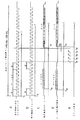
以下に、信号所要時間tD を算出する本発明の方法を図2a−2bに基づいて1つの例に対して説明する。これらの図中に示された実際の測定動作前の期間は、ここでは本発明の方法の一部だけを示す。 In the following, the method of the present invention for calculating the required signal time t D will be described for one example based on FIGS. 2a-2b. The period before the actual measurement operation shown in these figures shows only part of the method of the invention here.
これらの両図2a,2b中では、クロック線30.1,30.2上のクロック信号の経時変化が示されている。図2aは、時点t0 以降の評価ユニットからエンコーダ又は測定機器に伝送されるクロック信号の経時変化を示す。その一方で図2bは、エンコーダでの時点t10以降のクロック信号の経時変化を示す。図2a,2bから分かるように、エンコーダと評価ユニットとの間の伝送区間上のクロック信号の最終的な所要時間によって引き起こされる特定の時間のずれが、両時点t0 とt10との間に存在する。 In both FIGS. 2a and 2b, the change over time of the clock signal on the clock lines 30.1 and 30.2 is shown. Figure 2a shows the time course of the clock signal transmitted from the evaluation unit time t 0 after the encoder or measuring instruments. While Figure 2b shows the time course of time t 10 after the clock signal at the encoder. As can be seen from FIGS. 2a and 2b, a specific time lag caused by the final required time of the clock signal on the transmission interval between the encoder and the evaluation unit is between the instants t 0 and t 10. Exists.
エンコーダと評価ユニットとの間のデータ伝送を同期するクロック信号に関しては、対応する伝送クロック周波数fC が本発明を実施するために特にfC ≒100 - 200 kHz の大きさ内で選択される点に注意する必要がある。すなわち、本発明の方法を実施するために必要な伝送クロック周波数fC は、実際の測定動作中の例えばfC =4MHzに達し得る伝送クロック周波数fC よりも明らかに低く選択される。 For clock signals that synchronize the data transmission between the encoder and the evaluation unit, the corresponding transmission clock frequency f C is selected in particular within the magnitude of f C ≈100-200 kHz for implementing the invention. It is necessary to pay attention to. In other words, the transmission clock frequency f C required to implement the method of the present invention is selected to be clearly lower than the transmission clock frequency f C that can reach, for example, f C = 4 MHz during the actual measurement operation.
基本的には、予測される信号所要時間tD が伝送クロック周波数fC で伝送されるクロック線上のクロック信号のクロック周期tよりも小さいように、本発明の方法を実施する伝送クロック周波数fC が選択されることが好ましいと実証されている:
tD <1/fC =t (方程式1)
以下で説明する例では、信号所要時間tD が実際に正しく実施されることがこの条件を維持しつつ保証され得る。
Basically, the transmission clock frequency f C at which the method of the present invention is implemented is such that the predicted signal required time t D is smaller than the clock period t of the clock signal on the clock line transmitted at the transmission clock frequency f C. Has been demonstrated to be preferred:
t D <1 / f C = t (Equation 1)
In the example described below, it can be ensured while maintaining this condition that the signal duration t D is actually implemented correctly.
両図2c,2dは、データ線上の信号の経時変化を具体的に示す;この場合、図2cは、エンコーダでの信号の推移を示す。その一方で図2d中には、評価ユニット又は順次電子機器での信号の推移が示されている。ここでもまた、伝送区間上の信号所要時間によって引き起こされる時間のずれが、エンコーダでのデータ信号と評価ユニットでのデータ信号との間に存在する。すなわち、6ビットのモード命令の形態をした1つの二進データ語が、例えば時点t20に対して評価ユニットからエンコーダに伝送される。しかしこの二進データ語は、時点t30に初めてこのエンコーダに遅れて到着する。 Both FIGS. 2c and 2d specifically show the change over time of the signal on the data line; in this case, FIG. 2c shows the transition of the signal at the encoder. On the other hand, in FIG. 2d, the transition of the signal in the evaluation unit or sequentially in the electronic device is shown. Again, there is a time lag caused by the signal duration on the transmission interval between the data signal at the encoder and the data signal at the evaluation unit. That is, one binary data word in the form of a 6-bit mode command is transmitted from the evaluation unit to the encoder, for example at time t 20 . However, this binary data word, for the first time arrived late to the encoder at the time t 30.
次いで、データ、例えば対応する二進データ語の形態の位置データの伝送が、伝送されたモード命令を通じて評価ユニットによって要求される。シリアル伝送に対応するこれらのデータの評価後に、エンコーダは、時点t40に対して二進データ語の形態のデータの伝送を開始する。信号時間の所要時間が伝送区間にわたって発生するために、対応するデータ語は、時点t50に初めて評価ユニットに到着する。 The transmission of data, for example position data in the form of corresponding binary data words, is then requested by the evaluation unit through the transmitted mode command. Sheet after the evaluation of these data corresponding to the real transmission, the encoder begins transmission of data of binary data words in the form with respect to time t 40. The corresponding data word arrives at the evaluation unit for the first time at time t 50 because the required time of the signal time occurs over the transmission interval.
時点t50とクロック線上のクロック信号の最後の立ち上がりクロックエッジとの間の時間が、伝送区間によって引き起こされる算定すべき信号経過時間tD,i として規定される。この例では、クロック線上の評価ユニット側に対応する立ち上がりクロックエッジが、開始ビットを認識する前の最後の時点t35に対して存在する。 The time between time t 50 and the last rising clock edge of the clock signal on the clock line is defined as the signal elapsed time t D, i to be calculated caused by the transmission interval. In this example, the rising clock edge corresponding to the evaluation unit side of the clock line is present for the last time t 35 before recognizing the start bit.
図2e中に具体的に示されているように、信号経過時間tD,i を算出するため、カウンタが、最初に時点t31に対して評価ユニット側で開始する;このカウンタは、図1のブロック図中では符号21で概略的に示されている。このカウンタは、プリセットされているカウンタ周波数fZ で昇順に計数する。この場合、選択されるカウンタ周波数fZ は、測定動作中に使用されるクロック線上のクロック信号の伝送クロック周波数fC よりも明らかに高く選択される。特にこの場合、カウンタ周波数fZ は、測定動作中に使用される伝送クロック周波数fC よりも少なくとも8倍大きく選択される。すなわち、
fZ ≧8*fC (方程式2)
例えば伝送クロック周波数f C =4MHzが測定動作中に設定されている場合、カウンタ周波数fZ =32MHzが選択される。
As specifically shown in Figure 2e, in order to calculate the signal transit time t D, i, the counter starts the evaluation unit side first relative time t 31; this counter is 1 In the block diagram of FIG. This counter counts in ascending order by the counter frequency f Z of preset values. In this case, the selected counter frequency f Z is selected to be clearly higher than the transmission clock frequency f C of the clock signal on the clock line used during the measurement operation. Particularly in this case, the counter frequency f Z is selected at least 8 times greater than the transmission clock frequency f C used during the measurement operation. That is,
f Z ≧ 8 * f C (Equation 2)
For example, when the transmission clock frequency f C = 4 MHz is set during the measurement operation, the counter frequency f Z = 32 MHz is selected.
信号所要時間tD の十分に正確でかつノイズに強い算出を保証するため、選択されたカウンタ周波数fZ を最大で±10%程度変えてもよい。したがってfZ =32MHzの上の例では、最大で±3.2 MHzの周波数変化がさらに許容しうる。 The selected counter frequency f Z may be changed by about ± 10% at maximum in order to ensure that the signal required time t D is sufficiently accurate and noise-resistant. Therefore, in the above example with f Z = 32 MHz, a frequency change of ± 3.2 MHz at maximum can be further tolerated.
時点t31に対してクロック線上のクロック信号の1つの立ち上がり切替えエッジによって最初に開始するカウンタが、クロック信号の新たな立ち上がり切替えエッジによって新たに開始するか又は実際のカウンタ状態Zの伝送されるデータ語の到着する開始ビットの立ち上がりエッジによって検出されるか若しくは記憶されるまで、このカウンタはその都度昇順に計数する。したがってこの例では、カウンタが、図2eにしたがって時点t31〜t35に対してクロック信号の立ち上がり切替えエッジによって新たに開始する;時点t50に対してエンコーダZによって伝送される実際のカウンタ状態Zのデータ語の到着する開始ビットの上昇するサイクルエッジによって検出され記憶される。 The counter that starts first with one rising switching edge of the clock signal on the clock line for the time t 31 starts again with a new rising switching edge of the clock signal, or the actual counter state Z transmitted data This counter counts in ascending order each time it is detected or stored by the rising edge of the starting bit where the word arrives. Thus, in this example, the counter starts anew with a rising switching edge of the clock signal for times t 31 to t 35 according to FIG. 2e; the actual counter state Z transmitted by the encoder Z for time t 50 Is detected and stored by the rising cycle edge of the arriving start bit of the data word.
引き続き、信号所要時間tD,i が、評価ユニット側で既知のカウンタ周波数fZ と検出したカウンタ状態とから算定され得る、すなわち、tD,i =Z*1/fZ 。 Subsequently, the required signal time t D, i can be calculated from the known counter frequency f Z on the evaluation unit side and the detected counter state, ie t D, i = Z * 1 / f Z.
このようにして、信号所要時間tD,i (i=2)が、引き続き少なくとももう1回算定され、これらの個々の信号所要時間tD,1 ,tD,2 から平均の信号所要時間tD を算出する。本発明の方法のこの例では、信号所要時間tD,1 が、この説明した方法で全部で3回算定される(i=1,2,3)。引き続き、平均の信号所要時間tD が、算術的な平均値として個々の信号所要時間tD,i から算出される、すなわち、
tD =(tD,1 +tD,2 +tD,3 )/3 方程式(3)
信号所要時間tD,i のこの何回もの算出は、これらの信号所要時間tD,i の算出時の場合によっては発生する誤差が排除され得ること、及び算出したこれらの個々の値tD,i の持続する検査が可能であることを保証する。明らかに、3つよりも多いこれらの個々の値tD,i も、算定され得、平均の信号所要時間tD も、算術的な平均値を求めることによってこれらの個々の値tD,i から導き出され得る。
In this way, the signal required time t D, i (i = 2) is subsequently calculated at least once more , and the average signal required time t from these individual signal required times t D, 1 , t D, 2. D is calculated. In this example of the method according to the invention, the signal duration t D, 1 is calculated a total of three times with the described method (i = 1, 2, 3). Subsequently, the average signal duration t D is calculated from the individual signal durations t D, i as an arithmetic mean value, ie
t D = (t D, 1 + t D, 2 + t D, 3 ) / 3 Equation (3)
Signal duration t D, also calculated the number of times of i, these signals required time t D, it is the case of the calculation of the i error occurring can be eliminated, and calculated for these individual values t D , to guarantee that i can be tested continuously. Obviously, more than three of these individual values t D, i can also be calculated, and the average signal duration t D is also determined by determining the arithmetic mean value of these individual values t D, i. Can be derived from
個々の信号所要時間tD,i から平均値を求めた後に、これらの個々の信号所要時間tD,i がどの程度ΔtD,i 平均の信号所要時間tD からずれているかをさらに検査することが有益であることが実証されている。すなわち、個々に算出した信号所要時間tD,i の平均値tD からの最大に可能なずれΔtD,i が、測定動作中の伝送クロック周波数fC のクロック期間Tの最大で1/8でもよいことが例えば提唱され得る、すなわち、
ΔtD,i <(1/8)*(1/fC ) 方程式(4)
許容できないより大きなずれの場合、エラーメッセージが評価ユニット側から出力され、そして信号所要時間tD,i の算定が繰り返される。
Individual signal duration t D, after the average value was determined from i, further checks whether these individual signal duration t D, i is displaced from the degree Delta] t D, i average signal duration of t D Has proven to be beneficial. That is, the maximum possible deviation Δt D, i from the average value t D of the individually calculated signal required time t D, i is 1/8 at the maximum of the clock period T of the transmission clock frequency f C during the measurement operation. It may be advocated, for example, that is,
Δt D, i <(1/8) * (1 / f C ) Equation (4)
In the case of an unacceptably larger deviation, an error message is output from the evaluation unit side and the calculation of the signal duration t D, i is repeated.
こうして信号所要時間tD が算定された後に、これらの値が、エンコーダによって受信されたデータの処理時に評価ユニット側で後で考慮され得る。 After the signal duration t D has thus been calculated, these values can be taken into account later on the evaluation unit side when processing the data received by the encoder.
最後に、エンコーダと直列接続された評価ユニットとの間のシリアルデータ伝送のもう1つの構成を説明する。特に伝送区間が長く、そこから生じる信号所要時間が長い場合、この構成は、信号所要時間tD が本発明の方法にしたがって前もって算定してあるときに有益であることが実証されている。 Finally, another configuration of serial data transmission between the encoder and the evaluation unit connected in series will be described. This configuration has proven to be beneficial when the signal duration t D has been previously calculated according to the method of the present invention, particularly when the transmission interval is long and the signal duration resulting therefrom is long.
すなわちこの場合、エンコーダからのデータの要求ごとの測定動作中に、エンコーダが評価ユニットの方向にデータをもはや送信しないことが第1に提唱される。このようにして、さもなければ起こり得るデータ線上での衝突を回避しなければならない。この目的のため、まず最初に論理LOWレベルの遅延信号が、データ要求時に評価ユニットからエンコーダに伝送クロック線上で伝送される。この遅延信号は、プリセットされた特定の期間tSTを有する。その都度の伝送周波数fC を呈する実際のクロック信号が、この期間tST後になって初めて従来の方法で伝送され、このデータ伝送が進行する。したがって、伝送されるこのクロック信号の最初の周期が、論理LOWレベルと期間tSTを呈する遅延信号の伝送並びに引き続く伝送クロック期間t/2を呈する論理HIGHレベルから構成される。遅延信号の期間tSTは、例えばtST=1.5 μs に選択される。 That is, in this case, during the measuring operation for each request for data from the encoder, it is first proposed that the encoder no longer sends data in the direction of the evaluation unit. In this way, collisions on data lines that could otherwise occur must be avoided. For this purpose, first, a logic LOW level delay signal is transmitted from the evaluation unit to the encoder on the transmission clock line when data is requested. This delayed signal has a preset specific period tST . Actual clock signal exhibiting a transmission frequency f C in each case is transmitted in a first conventional method is later this period t ST, the data transmission progresses. Thus, the first period of the clock signal to be transmitted, and a logic HIGH level exhibiting a transmission clock period t / 2 following the transmission sequence of delay signals exhibiting logic LOW level and duration t ST. The delay signal period t ST is selected, for example, as t ST = 1.5 μs.
この説明した例に加えて、本発明の方法のその他の実施の形態が明らかに存在する。 In addition to this described example, there are clearly other embodiments of the method of the present invention.
10 エンコーダ
20 評価ユニット
21 カウンタ
30.1 信号線
30.2 信号線
31.1 信号線
31.2 信号線
40 電動機ハウジング
10
Claims (14)
−データのシリアル伝送が、エンコーダ(10)から評価ユニット(20)方向に要求され、
−プリセットされているカウンタ周波数(fZ )で昇順に計数するカウンタ(21)が、所定の開始時点(t31−t35)に対して評価ユニット(20)側で始動し、
−エンコーダ(10)によって要求された後に伝送されるデータ語が評価ユニット(20)側で検出された直後に、実際のカウンタ状態(Z)が時点(t50)に対して検出され、−信号所要時間(tD,j )が、この検出されたカウンタ状態(Z)から算出されることによって、測定動作前にエンコーダ(10)と評価ユニット(20)との間の信号所要時間(tD )が算出され、
−この場合、プリセットされているカウンタ周波数(f Z )は、測定動作中に使用されるクロック線(30.1,30.2)上のクロック信号の伝送クロック周波数(f C )よりも明らかに高く選択され、データ線(31.1,31.2)上のデータの伝送が、このクロック信号によってクロックされ、及び
−信号所要時間(t D,i )を算出する間のクロック線(30.1,30.2)上のクロック信号の選択された伝送クロック周波数(f C )は、測定動作中のクロック線(30.1,30.2)上のクロック信号の伝送クロック周波数(f C )よりも明らかに低く選択されることを特徴とする方法。 In a method for calculating a signal required time (tD) between an encoder (10) and an evaluation unit (20) connected in series to the encoder (10) for reprocessing position data,
A serial transmission of data is requested from the encoder (10) in the direction of the evaluation unit (20);
A counter (21) counting in ascending order with a preset counter frequency (fZ) is started on the evaluation unit (20) side for a predetermined start time (t31-t35);
Immediately after the data word to be transmitted after being requested by the encoder (10) is detected on the evaluation unit (20) side, the actual counter state (Z) is detected with respect to the instant (t50) and the signal required By calculating the time (tD, j) from the detected counter state (Z), the signal required time (tD) between the encoder (10) and the evaluation unit (20) is calculated before the measurement operation. And
-In this case, the preset counter frequency (f Z ) is clearly more than the transmission clock frequency (f C ) of the clock signal on the clock lines (30.1, 30.2) used during the measurement operation. Highly selected, the transmission of data on the data lines (31.1, 31.2) is clocked by this clock signal, and
The selected transmission clock frequency (f C ) of the clock signal on the clock line (30.1, 30.2) during the calculation of the signal required time (t D, i ) is equal to the clock line ( 30.1, 30.2), which is selected to be clearly lower than the transmission clock frequency (f C ) of the clock signal on .
Applications Claiming Priority (2)
| Application Number | Priority Date | Filing Date | Title |
|---|---|---|---|
| DE10125533A DE10125533B4 (en) | 2001-05-23 | 2001-05-23 | Method for operating a position-measuring device and position-measuring device and evaluation unit for carrying out the method |
| PCT/EP2002/004993 WO2002095513A2 (en) | 2001-05-23 | 2002-05-07 | Method for operating a position measuring device |
Publications (3)
| Publication Number | Publication Date |
|---|---|
| JP2004527056A JP2004527056A (en) | 2004-09-02 |
| JP2004527056A5 JP2004527056A5 (en) | 2005-12-22 |
| JP4235456B2 true JP4235456B2 (en) | 2009-03-11 |
Family
ID=7686123
Family Applications (1)
| Application Number | Title | Priority Date | Filing Date |
|---|---|---|---|
| JP2002591922A Expired - Fee Related JP4235456B2 (en) | 2001-05-23 | 2002-05-07 | Encoder operation |
Country Status (8)
| Country | Link |
|---|---|
| US (1) | US7043398B2 (en) |
| EP (1) | EP1395885B1 (en) |
| JP (1) | JP4235456B2 (en) |
| CN (1) | CN100444068C (en) |
| AT (1) | ATE318421T1 (en) |
| DE (2) | DE10125533B4 (en) |
| ES (1) | ES2258634T3 (en) |
| WO (1) | WO2002095513A2 (en) |
Families Citing this family (10)
| Publication number | Priority date | Publication date | Assignee | Title |
|---|---|---|---|---|
| JP2000015040A (en) * | 1998-07-01 | 2000-01-18 | Nihon Yamamura Glass Co Ltd | Gas separation membrane |
| DE10224627A1 (en) * | 2002-06-04 | 2003-12-24 | Heidenhain Gmbh Dr Johannes | Method for serial data transmission between a position measuring device and a processing unit |
| JP5845434B2 (en) * | 2010-03-11 | 2016-01-20 | パナソニックIpマネジメント株式会社 | Motor drive device |
| JP2013108838A (en) * | 2011-11-21 | 2013-06-06 | Nidec Sankyo Corp | Encoder equipped apparatus and encoder device |
| EP2725325B1 (en) * | 2012-10-26 | 2019-12-11 | Robert Bosch Gmbh | Position measurement system |
| JP6182924B2 (en) * | 2013-03-25 | 2017-08-23 | オムロン株式会社 | Synchronous serial interface circuit and motion control function module |
| DE102013224375A1 (en) * | 2013-11-28 | 2015-05-28 | Dr. Johannes Heidenhain Gmbh | Multi-turn encoders |
| DE102014225867A1 (en) | 2014-12-15 | 2016-06-16 | Dr. Johannes Heidenhain Gmbh | Device and method for checking a working clock signal of a position-measuring device |
| DE102018209136A1 (en) * | 2018-06-08 | 2019-12-12 | Dr. Johannes Heidenhain Gmbh | Position measuring device and method for operating a position measuring device |
| EP3771136A1 (en) * | 2019-07-23 | 2021-01-27 | Siemens Aktiengesellschaft | Installed module and method for operating an installed module |
Family Cites Families (23)
| Publication number | Priority date | Publication date | Assignee | Title |
|---|---|---|---|---|
| US204355A (en) * | 1878-05-28 | Improvement in machines for chopping meat | ||
| DE3612609A1 (en) * | 1986-04-15 | 1987-10-22 | Heidenhain Gmbh Dr Johannes | DEVICE FOR SERIAL TRANSFER OF DIGITAL MEASURED VALUES AT LEAST ONE MEASURED VALUE CONVERTER |
| CN87210258U (en) * | 1987-07-22 | 1988-07-13 | 李明远 | Display and alarm device for speed |
| CN2035076U (en) * | 1988-04-26 | 1989-03-29 | 黄石机械自动化研究所 | Cable length intelligent measure instrument |
| EP0408969B1 (en) * | 1989-07-14 | 1995-10-18 | Siemens Aktiengesellschaft | Arrangement for propagation time compensation and for jitter cleaning of a received data signal |
| DE4324197C2 (en) * | 1992-08-04 | 1998-07-09 | Asm Automation Sensorik Messte | Arrangement for analog / digital conversion and for serial transmission of the measured values of at least one sensor element |
| US5347227A (en) * | 1992-12-10 | 1994-09-13 | At&T Bell Laboratories | Clock phase adjustment between duplicated clock circuits |
| US5724392A (en) * | 1993-10-04 | 1998-03-03 | Siemens Business Communication Systems, Inc. | Automatic path delay compensation system |
| DE4342377B4 (en) | 1993-12-13 | 2010-08-12 | Dr. Johannes Heidenhain Gmbh | Arrangement and method for serial data transmission of a position measuring device |
| FI101833B (en) * | 1994-07-13 | 1998-08-31 | Nokia Telecommunications Oy | Method and apparatus for automatically compensating for cable delay in a clock signal distribution system |
| JP3509943B2 (en) * | 1994-07-20 | 2004-03-22 | 株式会社アドバンテスト | Transmission path propagation delay time measurement circuit |
| DE19508834C2 (en) * | 1995-03-11 | 1996-12-19 | Heidenhain Gmbh Dr Johannes | Position measuring system |
| JP3294737B2 (en) * | 1994-10-13 | 2002-06-24 | ドクトル・ヨハネス・ハイデンハイン・ゲゼルシヤフト・ミツト・ベシユレンクテル・ハフツング | Position measuring device |
| JPH10222464A (en) * | 1997-01-31 | 1998-08-21 | Mitsubishi Electric Corp | Synchronous serial data transfer device |
| DE19711216C1 (en) * | 1997-03-18 | 1998-05-07 | Heidenhain Gmbh Dr Johannes | Transmitting data between position measuring device and analysis unit, e.g. in machine tool |
| US6265951B1 (en) * | 1997-11-15 | 2001-07-24 | Cybex Computer Products Corporation | Method and apparatus for equalizing channel characteristics in a computer extension system |
| US6282593B1 (en) * | 1998-05-08 | 2001-08-28 | Tony Goodfellow | Extension of electronic buses and their bus protocols using signal-propagation timing compensation |
| DE19917354B4 (en) * | 1999-04-16 | 2005-12-22 | Siemens Ag | Synchronization method for a main unit and at least one subsidiary unit with internal timers to be synchronized with each other, communication system corresponding thereto, and main unit and slave unit of such a communication system |
| DE19933491A1 (en) | 1999-07-09 | 2001-02-01 | Walter Mehner | Method for serial transmission of digital measurement data |
| ATE371167T1 (en) * | 2000-02-17 | 2007-09-15 | Heidenhain Gmbh Dr Johannes | POSITION MEASURING DEVICE AND METHOD FOR OPERATING THE SAME |
| US6771076B1 (en) * | 2000-06-30 | 2004-08-03 | Andrew L. Smith | Method and apparatus for measurement of length of cable having fixed impedance |
| US6646454B2 (en) * | 2002-01-07 | 2003-11-11 | Test-Um, Inc. | Electronic apparatus and method for measuring length of a communication cable |
| US6608574B1 (en) * | 2002-03-29 | 2003-08-19 | Siemens Energy & Automation, Inc. | Device, system, and method for compensating for isolation and cable delays in an SSI encoder interface circuit |
-
2001
- 2001-05-23 DE DE10125533A patent/DE10125533B4/en not_active Expired - Fee Related
-
2002
- 2002-05-07 WO PCT/EP2002/004993 patent/WO2002095513A2/en active IP Right Grant
- 2002-05-07 ES ES02735341T patent/ES2258634T3/en not_active Expired - Lifetime
- 2002-05-07 JP JP2002591922A patent/JP4235456B2/en not_active Expired - Fee Related
- 2002-05-07 DE DE50205875T patent/DE50205875D1/en not_active Expired - Lifetime
- 2002-05-07 US US10/478,909 patent/US7043398B2/en not_active Expired - Lifetime
- 2002-05-07 CN CNB02810322XA patent/CN100444068C/en not_active Expired - Fee Related
- 2002-05-07 AT AT02735341T patent/ATE318421T1/en not_active IP Right Cessation
- 2002-05-07 EP EP02735341A patent/EP1395885B1/en not_active Expired - Lifetime
Also Published As
| Publication number | Publication date |
|---|---|
| WO2002095513A3 (en) | 2003-12-04 |
| EP1395885A2 (en) | 2004-03-10 |
| EP1395885B1 (en) | 2006-02-22 |
| CN1511276A (en) | 2004-07-07 |
| ES2258634T3 (en) | 2006-09-01 |
| CN100444068C (en) | 2008-12-17 |
| WO2002095513A2 (en) | 2002-11-28 |
| US7043398B2 (en) | 2006-05-09 |
| JP2004527056A (en) | 2004-09-02 |
| DE50205875D1 (en) | 2006-04-27 |
| ATE318421T1 (en) | 2006-03-15 |
| DE10125533B4 (en) | 2005-06-02 |
| DE10125533A1 (en) | 2002-11-28 |
| US20040193624A1 (en) | 2004-09-30 |
Similar Documents
| Publication | Publication Date | Title |
|---|---|---|
| EP0846993B1 (en) | Synchronizing method for communication | |
| JP4235456B2 (en) | Encoder operation | |
| US7925462B2 (en) | Position-measuring device and method for transmitting information concerning movement | |
| CN110879298B (en) | Speed acquisition method based on communication type encoder | |
| JP2012208935A (en) | Check method for position corresponding value and monitoring unit for checking position corresponding value | |
| CN105702016B (en) | Device and method for checking an operating clock signal of a position measuring device | |
| US4573139A (en) | System for position sensing transducers | |
| JP4139226B2 (en) | Method for operating a position measuring device and a position measuring device suitable for this method | |
| JP2008148504A (en) | Motor control unit, motor control system and arithmetic processing method for controlling motor control unit | |
| JP2007163500A (en) | System and method for establishing decoder processing velocity, adjusting orthogonal encoder | |
| US6704685B2 (en) | Method and device for determining the signal running time between a position measuring system and a processing unit | |
| CN107820672B (en) | Motor control system, driver, inverter, control method, computer software, and storage medium | |
| JP2004527056A5 (en) | ||
| JP4351162B2 (en) | Method for operating a position measuring device and a position measuring device suitable for this | |
| CN108856307A (en) | A kind of mechanical equipment position detecting device and detection method | |
| US6466890B1 (en) | Device for detecting rotational position deviation | |
| KR200465177Y1 (en) | Motor controller | |
| JP2010513998A (en) | Pulse sending device for sending trigger pulse accurately in position | |
| KR101722862B1 (en) | Appratus for controlling motor | |
| JP4352500B2 (en) | COMMUNICATION METHOD AND COMMUNICATION SYSTEM FOR COMMUNICATION SYSTEM | |
| KR100400593B1 (en) | Position decision controller of motor | |
| JPH1034401A (en) | Main spindle synchronization control method and device therefor | |
| KR19990001541A (en) | Speed detection method and device | |
| JP2004015802A (en) | Method and apparatus for transmitting serial data between position measuring instrument and processing unit | |
| JPH0839298A (en) | Slide stop time measuring instrument of press machine |
Legal Events
| Date | Code | Title | Description |
|---|---|---|---|
| A521 | Request for written amendment filed |
Free format text: JAPANESE INTERMEDIATE CODE: A523 Effective date: 20050121 |
|
| A621 | Written request for application examination |
Free format text: JAPANESE INTERMEDIATE CODE: A621 Effective date: 20050121 |
|
| A131 | Notification of reasons for refusal |
Free format text: JAPANESE INTERMEDIATE CODE: A131 Effective date: 20080122 |
|
| A521 | Request for written amendment filed |
Free format text: JAPANESE INTERMEDIATE CODE: A523 Effective date: 20080327 |
|
| TRDD | Decision of grant or rejection written | ||
| A01 | Written decision to grant a patent or to grant a registration (utility model) |
Free format text: JAPANESE INTERMEDIATE CODE: A01 Effective date: 20081209 |
|
| A01 | Written decision to grant a patent or to grant a registration (utility model) |
Free format text: JAPANESE INTERMEDIATE CODE: A01 |
|
| A61 | First payment of annual fees (during grant procedure) |
Free format text: JAPANESE INTERMEDIATE CODE: A61 Effective date: 20081215 |
|
| FPAY | Renewal fee payment (event date is renewal date of database) |
Free format text: PAYMENT UNTIL: 20111219 Year of fee payment: 3 |
|
| R150 | Certificate of patent or registration of utility model |
Free format text: JAPANESE INTERMEDIATE CODE: R150 Ref document number: 4235456 Country of ref document: JP Free format text: JAPANESE INTERMEDIATE CODE: R150 |
|
| FPAY | Renewal fee payment (event date is renewal date of database) |
Free format text: PAYMENT UNTIL: 20111219 Year of fee payment: 3 |
|
| FPAY | Renewal fee payment (event date is renewal date of database) |
Free format text: PAYMENT UNTIL: 20121219 Year of fee payment: 4 |
|
| R250 | Receipt of annual fees |
Free format text: JAPANESE INTERMEDIATE CODE: R250 |
|
| FPAY | Renewal fee payment (event date is renewal date of database) |
Free format text: PAYMENT UNTIL: 20121219 Year of fee payment: 4 |
|
| FPAY | Renewal fee payment (event date is renewal date of database) |
Free format text: PAYMENT UNTIL: 20131219 Year of fee payment: 5 |
|
| R250 | Receipt of annual fees |
Free format text: JAPANESE INTERMEDIATE CODE: R250 |
|
| R250 | Receipt of annual fees |
Free format text: JAPANESE INTERMEDIATE CODE: R250 |
|
| R250 | Receipt of annual fees |
Free format text: JAPANESE INTERMEDIATE CODE: R250 |
|
| R250 | Receipt of annual fees |
Free format text: JAPANESE INTERMEDIATE CODE: R250 |
|
| R250 | Receipt of annual fees |
Free format text: JAPANESE INTERMEDIATE CODE: R250 |
|
| R250 | Receipt of annual fees |
Free format text: JAPANESE INTERMEDIATE CODE: R250 |
|
| R250 | Receipt of annual fees |
Free format text: JAPANESE INTERMEDIATE CODE: R250 |
|
| R250 | Receipt of annual fees |
Free format text: JAPANESE INTERMEDIATE CODE: R250 |
|
| R250 | Receipt of annual fees |
Free format text: JAPANESE INTERMEDIATE CODE: R250 |
|
| LAPS | Cancellation because of no payment of annual fees |