JP2004015802A - Method and apparatus for transmitting serial data between position measuring instrument and processing unit - Google Patents
Method and apparatus for transmitting serial data between position measuring instrument and processing unit Download PDFInfo
- Publication number
- JP2004015802A JP2004015802A JP2003100396A JP2003100396A JP2004015802A JP 2004015802 A JP2004015802 A JP 2004015802A JP 2003100396 A JP2003100396 A JP 2003100396A JP 2003100396 A JP2003100396 A JP 2003100396A JP 2004015802 A JP2004015802 A JP 2004015802A
- Authority
- JP
- Japan
- Prior art keywords
- data
- request command
- pos
- processing unit
- measuring device
- Prior art date
- Legal status (The legal status is an assumption and is not a legal conclusion. Google has not performed a legal analysis and makes no representation as to the accuracy of the status listed.)
- Granted
Links
Images


Classifications
-
- G—PHYSICS
- G05—CONTROLLING; REGULATING
- G05B—CONTROL OR REGULATING SYSTEMS IN GENERAL; FUNCTIONAL ELEMENTS OF SUCH SYSTEMS; MONITORING OR TESTING ARRANGEMENTS FOR SUCH SYSTEMS OR ELEMENTS
- G05B19/00—Programme-control systems
- G05B19/02—Programme-control systems electric
- G05B19/18—Numerical control [NC], i.e. automatically operating machines, in particular machine tools, e.g. in a manufacturing environment, so as to execute positioning, movement or co-ordinated operations by means of programme data in numerical form
- G05B19/408—Numerical control [NC], i.e. automatically operating machines, in particular machine tools, e.g. in a manufacturing environment, so as to execute positioning, movement or co-ordinated operations by means of programme data in numerical form characterised by data handling or data format, e.g. reading, buffering or conversion of data
-
- G—PHYSICS
- G05—CONTROLLING; REGULATING
- G05B—CONTROL OR REGULATING SYSTEMS IN GENERAL; FUNCTIONAL ELEMENTS OF SUCH SYSTEMS; MONITORING OR TESTING ARRANGEMENTS FOR SUCH SYSTEMS OR ELEMENTS
- G05B2219/00—Program-control systems
- G05B2219/30—Nc systems
- G05B2219/31—From computer integrated manufacturing till monitoring
- G05B2219/31137—Sercos serial real time communications system between servo and cpu
-
- G—PHYSICS
- G05—CONTROLLING; REGULATING
- G05B—CONTROL OR REGULATING SYSTEMS IN GENERAL; FUNCTIONAL ELEMENTS OF SUCH SYSTEMS; MONITORING OR TESTING ARRANGEMENTS FOR SUCH SYSTEMS OR ELEMENTS
- G05B2219/00—Program-control systems
- G05B2219/30—Nc systems
- G05B2219/31—From computer integrated manufacturing till monitoring
- G05B2219/31145—Ethernet
-
- G—PHYSICS
- G05—CONTROLLING; REGULATING
- G05B—CONTROL OR REGULATING SYSTEMS IN GENERAL; FUNCTIONAL ELEMENTS OF SUCH SYSTEMS; MONITORING OR TESTING ARRANGEMENTS FOR SUCH SYSTEMS OR ELEMENTS
- G05B2219/00—Program-control systems
- G05B2219/30—Nc systems
- G05B2219/33—Director till display
- G05B2219/33187—Serial transmission rs232c, rs422, rs485 communication link
-
- G—PHYSICS
- G05—CONTROLLING; REGULATING
- G05B—CONTROL OR REGULATING SYSTEMS IN GENERAL; FUNCTIONAL ELEMENTS OF SUCH SYSTEMS; MONITORING OR TESTING ARRANGEMENTS FOR SUCH SYSTEMS OR ELEMENTS
- G05B2219/00—Program-control systems
- G05B2219/30—Nc systems
- G05B2219/33—Director till display
- G05B2219/33251—Schedule periodic and aperiodic traffic, real time, time critical
-
- G—PHYSICS
- G05—CONTROLLING; REGULATING
- G05B—CONTROL OR REGULATING SYSTEMS IN GENERAL; FUNCTIONAL ELEMENTS OF SUCH SYSTEMS; MONITORING OR TESTING ARRANGEMENTS FOR SUCH SYSTEMS OR ELEMENTS
- G05B2219/00—Program-control systems
- G05B2219/30—Nc systems
- G05B2219/34—Director, elements to supervisory
- G05B2219/34406—Effect of computer, communication delay in real time control
-
- G—PHYSICS
- G05—CONTROLLING; REGULATING
- G05B—CONTROL OR REGULATING SYSTEMS IN GENERAL; FUNCTIONAL ELEMENTS OF SUCH SYSTEMS; MONITORING OR TESTING ARRANGEMENTS FOR SUCH SYSTEMS OR ELEMENTS
- G05B2219/00—Program-control systems
- G05B2219/30—Nc systems
- G05B2219/41—Servomotor, servo controller till figures
- G05B2219/41173—Delay of compensation output signal as function of sampling and computation time
-
- G—PHYSICS
- G05—CONTROLLING; REGULATING
- G05B—CONTROL OR REGULATING SYSTEMS IN GENERAL; FUNCTIONAL ELEMENTS OF SUCH SYSTEMS; MONITORING OR TESTING ARRANGEMENTS FOR SUCH SYSTEMS OR ELEMENTS
- G05B2219/00—Program-control systems
- G05B2219/30—Nc systems
- G05B2219/41—Servomotor, servo controller till figures
- G05B2219/41431—Delay position command as function of calculation time for feedforward, or order of system
-
- Y—GENERAL TAGGING OF NEW TECHNOLOGICAL DEVELOPMENTS; GENERAL TAGGING OF CROSS-SECTIONAL TECHNOLOGIES SPANNING OVER SEVERAL SECTIONS OF THE IPC; TECHNICAL SUBJECTS COVERED BY FORMER USPC CROSS-REFERENCE ART COLLECTIONS [XRACs] AND DIGESTS
- Y02—TECHNOLOGIES OR APPLICATIONS FOR MITIGATION OR ADAPTATION AGAINST CLIMATE CHANGE
- Y02P—CLIMATE CHANGE MITIGATION TECHNOLOGIES IN THE PRODUCTION OR PROCESSING OF GOODS
- Y02P90/00—Enabling technologies with a potential contribution to greenhouse gas [GHG] emissions mitigation
- Y02P90/02—Total factory control, e.g. smart factories, flexible manufacturing systems [FMS] or integrated manufacturing systems [IMS]
Landscapes
- Engineering & Computer Science (AREA)
- Human Computer Interaction (AREA)
- Manufacturing & Machinery (AREA)
- Physics & Mathematics (AREA)
- General Physics & Mathematics (AREA)
- Automation & Control Theory (AREA)
- Small-Scale Networks (AREA)
- Communication Control (AREA)
- Arrangements For Transmission Of Measured Signals (AREA)
- Information Transfer Systems (AREA)
Abstract
Description
【0001】
【発明の属する技術分野】
この発明は、位置測定装置と処理ユニットとの間におけるシリアルデータ伝送方法に関する。
【0002】
【従来の技術】
出願人のドイツ特許公開第10030358号明細書により、位置測定装置と処理ユニットとの間におけるシリアルデータ伝送方法ならびに装置が周知であり、それは、例えば、位置測定装置で生成された位置データにもとづく、駆動ユニットの高度に動的な制御を可能とするものである。この印刷物には、基本的にそれに対応するように設計されたデジタルインタフェースの相応のプロトコル構造が開示されており、それによって処理ユニットと位置測定装置との間における高速で、割込み能力を持つポイントツーポイント接続が可能となるものである。このインタフェースの具体的な物理構成に関して、そこで提案されているシリアルデータ伝送用のプロトコル構造は、幾つかの周知のインタフェース概念をベースとして実現することが可能であるとだけ記載されている。しかし、この印刷物には、その固有のインタフェース物理媒体の具体的な構成に関する詳細は記載されていない。
【0003】
同じことが、出願人のドイツ特許出願第10030357号明細書にも言え、そこにはさらに前述のドイツ特許公開第10030358号明細書のプロトコル構造を利用する場合に発生する問題の解決法が提案されており、それは、即ち位置要求コマンドまたは入力パルスに関する、場合によっては起こりうる時間的な曖昧性を取り除くものであり、インタフェースの割込み能力から生まれるものである。このような不確実性は、特にインタフェースのリアルタイム能力に対しては不都合であり、そのリアルタイム能力は、位置測定装置側における位置データの各入力が出来るだけ一定の遅延時間後に行われることに関する高い要求条件を求めるものである。
【0004】
ドイツ特許公開第10030358号明細書において周知のシリアルデータ伝送のための方式を、所謂イーサネット(登録商標)物理層と共に使用した場合、そのインタフェースの増強されたリアルタイム能力のために、別の問題が起こる。既に述べたとおり、高度に動的な制御においては、まず第一に、処理ユニット側で対応する位置要求コマンドが発生した場合に、その時点に関係なく、位置測定装置側において出来るだけ確定的な位置データの検出または入力が行われることが保証されなければならない。位置データの検出または入力時点に関する、場合によっては起こりうる時間的な曖昧性は、その結果として生じる制御品質において不利に作用する。インタフェースのイーサネット(登録商標)物理層と基本的な割込み能力を使用する場合、さらに別の措置なしにはリアルタイム能力が保証されない。
【0005】
【発明が解決しようとする課題】
そのことから、この発明の課題は、位置測定装置と処理ユニットとの間における割込み能力のあるシリアルデータ伝送方法を示すことであり、その際特にイーサネット(登録商標)物理層を使用する場合に、常に所定の時間で、かつ出来る限り小さな時間的な曖昧性でもって、位置測定装置での位置データの検出が行われることが保証されるものである。
【0006】
【課題を解決するための手段】
この課題は、請求項1の特徴を持った方法により解決される。
【0007】
この発明にもとづく方法の有利な実施構成は、請求項1の従属請求項に挙げられた措置から生じるものである。
【0008】
この発明にもとづき、処理ユニットから位置測定装置にデータが伝送されていないアイドル状態の時にちょうど位置要求コマンドが発生した場合、アイドル状態の終了後に第一遅延情報と共に位置要求コマンドを位置測定装置に伝送するものと規定される。位置測定装置側において、第一遅延情報は、処理ユニット側における位置要求コマンドの発生と位置測定装置側における位置要求コマンドの実行との間に常に一定の遅延時間が生じるように分析評価される。
【0009】
特に、所定の予め決まったデータ伝送方式でイーサネット(登録商標)物理媒体を使用する場合において、この発明にもとづく措置は、位置測定装置側での一定の遅延時間後における位置データの検出または入力を保証するものである、すなわち、このようなインタフェース概念のリアルタイム能力に対する要求を満たすことができるものである。この場合、一定の遅延時間後における位置データの検出は、処理ユニット側での非同期の位置要求コマンドが発生する可能性のある、どのような起こりうるケースにおいても保証される。そのため、この発明による方法は、割込み能力を持ち、そのことにより位置要求コマンドが発生する予め規定された固定クロックタイミングに依存しない。基本的には、非同期に発生する各位置要求コマンドに対して、位置測定装置側での一定の遅延時間後における位置データの検出を保証することができる。そのため、この発明による措置は、特に有利には、既に上述したドイツ特許公開第10030358号明細書により周知の方法と組み合わせて使用することができる。
【0010】
さらに、この発明にもとづく措置は、このようなデータ伝送の枠組みにおける位置測定装置と処理ユニットとの間の信号伝搬時間の決定を行うのに特に有利に利用することができる。
【0011】
【発明の実施の形態】
この発明の他の利点ならびに詳細は、添付図面にもとづく以下の実施例の記述から明らかとなる。
【0012】
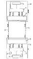
図1では、位置測定装置(ENCODER)10、信号伝送区間および処理ユニット(NC)20から成るシステムをおおまかに模式化したブロック接続図が描かれている。位置測定装置10と処理ユニット20との間のシリアルデータ伝送は、それぞれ一つまたは複数の導線から構成することができる二つのデータチャネル31,32を介して全二重動作で行われる。位置測定装置10において、位置データ、場合によっては別のデータが、詳しくは説明しない位置データ生成ユニット11またはその他の所で生成され、第一データチャネル31を介して処理ユニット10への連続的なデータストリームの形でシリアルデータ伝送するために、プロトコルモジュール12と通信モジュール13によって処理される。プロトコルモジュール12と通信モジュール13とは、相応のインタフェースと一連の導線を介して相互に接続され、それに関しては以下の記述の流れの中で詳しく取り上げる。通信モジュール13としては、有利には所謂ファーストイーサネット(登録商標)物理レイヤモジュール(イーサネット(登録商標)PHY)が使用され、それによって既存のイーサネット(登録商標)物理媒体の構成にもとづくシリアルデータ伝送は、周知の方法により処理されるものである。
【0013】
処理ユニット20側では、基本的に同じインタフェース・アーキテクチャが用いられる、すなわち伝送されたデータは、別の通信モジュール23とプロトコルモジュール22を介して位置データ処理ユニット21に供給され、そこでデータは適切に再処理される。これと同様にして、同じモジュールと第二データチャネル32を介して、処理ユニット20から位置測定装置10への方向のデータ伝送が可能である。この場合、そのデータは、例えば位置測定装置に伝送されるコマンドデータ、パラメータ指定データなどである。
【0014】
さらに、処理ユニット20側には、以下において状態自動機械24と称するユニット24がプロトコルモジュール22に配置されており、それはその時に伝送されたデータにもとづく所定の情報を供給するものであることに言及したい。この発明における、これの正確な機能は、以下の記述の流れの中でさらに詳細に説明する。
【0015】
ここでは、図1がアーキテクチャ全体の大まかな模式図だけを描いており、この発明の説明のために必要な構成要素だけが示されていることを指摘しておく。各構成要素を互いに接続する幾つかの導線については、図2〜4の以下の記述の流れの中でさらに詳しく取り上げる。当然のことながら、位置測定装置10と処理ユニット20は、機能に関連する別の構成要素を持つが、それらは見易さの理由から図1には描かれていない。
【0016】
具体的に使用する場合には、位置測定装置10は、例えば工作機械に配置され、機械の可動部分、例えば工作部分の位置決定に用いられ、数値工作機械制御部が処理ユニット20として機能する。この代わりに、位置測定装置10が電気駆動機の軸エンコーダであることも可能で、それに対応する駆動制御部などが処理ユニット20として機能する。
【0017】
図1と2にもとづき、以下に位置測定装置10と処理ユニット20との間の所定のシリアルデータ伝送における標準伝送モードを説明するが、その際この例では第二データチャネル32上における処理ユニット20から位置測定装置10への方向のデータ伝送だけを説明する。別の方向へのデータ伝送も、基本的に同様にして進行する。
【0018】
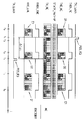
図2の上部では、処理ユニット(NC)側における一連の信号がデータ伝送の時間的な推移として描かれており、下部の二つの流れ図は、位置測定装置(ENCODER)側の状況を表している。
【0019】
基本的に、各プロトコルモジュール22と通信モジュール23との間のデータ伝送は、データパケットDで行われ、その際連続するデータパケットD間には所定の時間間隔ΔtPが保持されなければならない。データパケットDは、導線TXD_NC上をプロトコルモジュール22から通信モジュール23あるいはイーサネット(登録商標)PHYに伝送される。データパケットDが伝送可能となるためには、導線TXEN_NC上の信号がHIGHの論理レベルにならなければならず、一方その間にある伝送休止時間において、導線TXEN_NC上の論理レベルがLOWである。通信モジュール23からは、第二データチャネル32あるいは導線TX_NC上の各データの伝送が、位置測定装置10の方向に連続したデータストリームとして行われる。この場合、連続したデータストリームは、一つには様々なユーザデータを持つデータパケットDから成り、それらはユーザデータシンボル「RK6」、「DATA」、「DATA3」、・・・、「DATAn」等の形で伝送される。さらには、連続したデータストリームは、空のデータまたは空データシンボル「IDLE」を有し、これらは、図2に描かれている導線TX_NC上の状況から明らかなように、ユーザデータを持つデータパケットDの間に挿入されるものである。その下には、データパケットDの伝送が行われる時間または伝送フェーズが、使用フェーズΔTNとして表示されている。それらの間にある、データが伝送されていない時間または伝送フェーズは、アイドルフェーズΔTLとして表示されている。
【0020】
導線TX_NC上に伝送されるデータの形式に関しては、従来のイーサネット(商標登録)物理媒体の使用にもとづく所定の構造上の条件がある。そのため、伝送されるデータパケットDは、それぞれ所定の数のユーザデータシンボルから成り、その際各データパケットDは、二つの定義されたデータシンボル「シンボルJ」、「シンボルK」で始まり、データシンボル「シンボルT」、「シンボルR」で終わる。同様に、アイドルフェーズΔTLに伝送される最少数の空データシンボル「IDLE」が予め規定されているが、当然のことながら、実際に必要であれば、より長いアイドルフェーズΔTLとなることもあるので、その場合再びユーザデータを持つデータパケットDが伝送されるまでは、そこには相応のより多くの空データシンボル「IDLE」が伝送される。前述したリアルタイム要求に応えるため、ならびに出来るだけ高速なデータ交換を確保するため、この発明の枠組みにおいては、アイドルフェーズΔTLの空データシンボル「IDLE」の数NIDLEは、出来る限り小さくし、ここに挙げた例では空データシンボル「IDLE」の最少数NIDLE,minに関しては、NIDLE,min=7とされている、すなわち常にNIDLE,min≧7である。
【0021】
図2の下部では、処理ユニット20からのデータパケットDの伝送時における、位置測定装置10の通信モジュール13とプロトコルモジュール12との間の導線RXEN_ENCとRXD_ENC上の信号が描かれている。この場合、伝送中でデータパケットDが受信されている限り、通信モジュール13とプロトコルモジュール12との間の導線RXEN_ENC上において、それぞれに対応する信号は、使用フェーズΔTNでは論理レベルHIGHに、アイドルフェーズΔTLでは論理レベルLOWにされる。
【0022】
図2では、幾つかの導線上の前述した信号以外にも、状態自動機械24(STATE_MACHINE)で入手可能な進行するデータ伝送の状況に関する情報が描かれている。この状態自動機械24は、図示した実施例では、前述したとおり処理ユニット20側のプロトコルモジュール22に配置されている。この発明におけるこの機能については、以下の記述の流れの中で詳細に説明する。
【0023】
既に冒頭で述べたように、ここに挙げたインタフェースのリアルタイム能力に関しては、処理ユニット20側で発生する各位置要求コマンドに対して、位置測定装置10側での位置要求コマンドの実行、すなわちその時点の位置の入力が、一定の遅延時間後に行われるということが重要である。ここに挙げたインタフェースプロトコルの場合において、このような位置要求コマンドは、基本的に非同期に、すなわち各可能な時点に発生することができるので、データ伝送に際して、図2をもとに説明したように、位置要求コマンドが発生しうる幾つかのケースが考えられる。この場合、二つのケースがあり、それは対応する位置要求コマンドが、連続するデータ伝送の、
a)使用フェーズΔTN、または
b)アイドルフェーズΔTL
に発生するものである。この二つのケースにおいて、位置要求コマンドの一定の遅延時間後における実行、すなわち位置測定装置10のその時点の位置の入力が起こることを保証するためには、以下に図3と4をもとに説明する、この発明にもとづく措置が必要である。最後に、図5にもとづき、より長いアイドルフェーズの後に位置要求コマンドが発生する、ケースb)に対応する特別なケースについて記述する。
【0024】
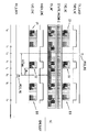
まず、処理ユニットから位置測定装置に向けての連続するデータ伝送の使用フェーズの間に位置要求コマンドPOS_RQが発生するケースについて、図3をもとに詳細に説明する。この場合、使用フェーズは、時点t0においてデータパケットD1の伝送で始まる。図3では、図2のように、また中間部に導線上におけるデータ伝送時の状況が図示されている。さらに、処理ユニット側での時点t1で発生した位置要求コマンドPOS_RQが図示されており、それは導線TX_Latch上をプロトコルモジュール22に伝えられ、それによって可能な限り即座に位置測定装置10にその時点の位置データの入力と伝送を要求するものである。位置要求コマンドPOS_RQにより、時点t1で導線TXD_NC上における通信モジュール23へのデータパケットD1の連続した伝送が中止されるか、あるいは導線TX_NC上における位置測定装置へのデータパケットD1の伝送が中断される。使用フェーズの間におけるデータパケットD1の伝送を規定どおりに終了するには、さらに導線TX_NC上において既に上述した二つのデータシンボル「シンボルT」、「シンボルR」の伝送が行われる。この場合、データシンボル「シンボルT」、「シンボルR」の伝送は、導線TXEN_NC上における信号がHIGHからLOWになったら直ぐに、通信モジュール23により自動的に行われ、この信号がLOWの値である限りは、空データシンボル「IDLE」の伝送が行われる。そのため、二つのデータシンボル「シンボルT」、「シンボルR」の伝送後の時点t2において、導線TX_NC上では、少なくともこれに対応するアイドルフェーズの全部でNIDLE,min=7個の空データシンボル「IDLE」の所要の伝送が始まる。アイドルフェーズの終了後の時点t3で、データパケットD2の伝送が開始し、境界を定めるデータシンボル「シンボルJ」、「シンボルK」と「シンボルT」、「シンボルR」との間にはユーザデータシンボル「RK0」と「DATA=0」が位置測定装置に伝送される。この場合、第一ユーザデータシンボル「RK0」が、処理可能となった対応する位置要求コマンドPOS_RQであり、第二ユーザデータシンボル「DATA=0」が、以下でまた説明する第二遅延情報である。
【0025】
図3の信号流れ図の下部に描かれている位置測定装置側の状況から分かるように、データパケットD2の伝送後の時点t4で、位置測定装置側の導線RX_Latch上には、対応する位置要求コマンドPOS_RQがあり、このコマンドを実行することができる、すなわちその時点における位置の入力を行うことができる。
【0026】
空データシンボル「IDLE」の伝送によるアイドルフェーズの更新後の時点t5で、その前の時点t1で位置要求コマンドPOS_RQの発生によって中断されたデータパケットD1全体が、最終的に再度位置測定装置に伝送される。時点t6でデータパケットD1の伝送が終了する。
【0027】
図3には、位置測定装置での位置要求コマンドPOS_RQの実行において、最終的に位置測定装置から処理ユニットへの生成された位置データが伝送される様子は描かれていない。
【0028】
ここに挙げたインタフェースのリアルタイム能力については、特に処理ユニット側で位置要求コマンドPOS_RQが発生する時点t1と位置測定装置側で位置要求コマンドPOS_RQの実行が可能となる時点t4との間の時間が、まさに重要である。これらの時点間にある遅延時間ΔTDELは、位置測定装置側の一定の遅延時間後における位置の検出を保証するためには、一つには出来るだけ小さく、さらには非同期に発生する位置要求コマンドPOS_RQの各ケースにおいて出来るだけ同じであることが求められる。位置要求コマンドPOS_RQが処理ユニット側の即座に中断可能な使用フェーズの間に発生する、ここに記述したケースでは、遅延時間ΔTDELを最小化するための他の措置は必要ではない。データパケットD1の伝送中止後に続いて、アイドルフェーズでの最小限(NIDLE,min=7)必要な空データシンボル「IDLE」の伝送だけが行われ、続いて位置要求コマンドに関するユーザデータシンボル「RK0」を持つデータパケットD2を伝送することができる。そのため、時点t1とt4間にある時間間隔は、位置要求コマンドPOS_RQが使用フェーズに発生する場合における、実現可能な最小の遅延時間ΔTDELを示すものである。この場合、場合によって必要な修正措置は、必要ではない。そのため、データパケットD2で伝送される第二遅延情報または対応するユーザデータシンボルは、「DATA=0」の値に設定される。
【0029】
それに対して、処理ユニットから位置測定装置への連続するデータ伝送のアイドルフェーズの間に位置要求コマンドPOS_RQが発生するケースにおいては、別の状況とそこでの必要な措置が生じる。このケースについては、以下で図4をもとに詳しく説明する。また、図2と3と同様に、幾つかの導線上における信号の伝送が描かれている。
【0030】
処理ユニット側において、時点t0とt1間における幾つかのユーザデータまたはユーザデータシンボル「RK6」、「DATA」等を持つデータパケットD1の伝送後に続くアイドルフェーズの進行中の時点t2で、まさに位置要求コマンドPOS_RQが発生する。この場合、ここに挙げた例の位置要求コマンドPOS_RQは、4つのアイドルシンボル「IDLE」等の伝送が既に実行された後のアイドルフェーズで発生する。この情報、すなわち位置要求コマンドがアイドルフェーズのどの時点で発生したかという情報は、既に述べた状態自動機械24において利用可能である。以下では、この情報を第一遅延情報と呼ぶ。別の言葉で表現すると、状態自動機械24の情報から、アイドルフェーズの間における位置要求コマンドPOS_RQの時間的な位置を導き出すことができる。
【0031】
図2には、それ以後の図でも同様に、データ伝送の進行中の状態自動機械において利用可能な情報は、流れ図で「STATE_MACHINE」と表示された部分に描かれている。
【0032】
イーサネット(登録商標)物理媒体を基礎として選択したデータ伝送方法を前提として、アイドルフェーズは、直ぐには終了することはできない。それどころか、最小限NIDLE,min=7個のアイドルシンボル「IDLE」の伝送とそれによる最低限可能なアイドルフェーズの規定通りの終了が必要である。結局は、時点t3において初めて、位置測定装置へのデータパケットD2と処理可能となった対応する位置要求コマンドの伝送を開始することができる。データパケットD2の開始に対して、また必要なデータシンボル「シンボルJ」、「シンボルK」が伝送され、それには位置要求コマンドを示すユーザデータシンボル「シンボルRK0」が続く。ユーザデータシンボル「RK0」のデータフレームに続いて、ユーザデータシンボル「DATA=4」を持つデータフレームの伝送が行われる。このユーザデータシンボルは、第一遅延情報を示し、具体的な例ではアイドルフェーズ時の位置要求コマンドPOS_RQの時間的な位置がどのようであったかを示すものである。時点t4での位置要求コマンドPOS_RQと第一遅延情報に関する対応する情報を持つデータパケットD2の伝送終了後における時点t5で、最終的に位置測定装置側の位置要求コマンドPOS_RQの実行、すなわちその時点の位置の入力が行われる。
【0033】
図4から明らかなように、位置測定装置側では、伝送されたユーザデータシンボル「DATA=4」を持つ、データパケットD2で伝送された第一遅延情報は、時点t4でのデータパケットD2の伝送終了後から所定の遅延時間間隔DELが経過してからようやく位置要求コマンドPOS_RQの実行が開始するように分析評価される。この場合、遅延時間間隔DELは、伝送された第一遅延情報または対応するユーザデータシンボル「DATA=4」、すなわち時点t1でアイドルフェーズが開始した後から時点t2で位置要求コマンドPOS_RQが発生するまでの時間に相当する。そのため、この遅延時間間隔DELは、この例ではDEL=t2−t1から得られる。
【0034】
このことから、このケースにおいても、このようにコマンドの実行を遅延させることによって、時点t2での位置要求コマンドPOS_RQの発生と時点t5での位置要求コマンドPOS_RQの実行との間には、図3の上述したケースにおける遅延時間ΔTDELと同じ遅延時間ΔTDELが生じる。これによって、位置要求コマンドPOS_RQが発生する時点に関わらずに、位置要求コマンドPOS_RQの一定の遅延時間後における実行が保証される。
【0035】
続くアイドルフェーズの終了後の時点t6で、次のデータパケットD3の伝送が始まり、時点t7で終了する、以下同様である。
【0036】
二つの説明したケースから明らかなように、位置要求コマンドPOS_RQの伝送が発生する位置に応じた第一または第二遅延情報の伝送によって、位置要求コマンドPOS_RQの発生と位置測定装置の実行との間に、常に確定的な、すなわち有利には一定の時間間隔または遅延時間ΔTDELが生じることが保証される。この場合、遅延情報は、位置要求コマンドPOS_RQが発生する時点に関係なく、一定の遅延時間ΔTDELが保証されるように選択される。
【0037】
ここに挙げたケースでは、遅延時間ΔTDELは、予め規定した数NIDLEの空データシンボル「IDLE」に対する各データシンボルの伝送時間と、データパケットDの始めのデータシンボルである「シンボルJ」、「シンボルK」と終わりのデータシンボルである「シンボルT」、「シンボルR」の送信に対する伝送時間と、位置要求コマンドPOS_RQおよび第一または第二遅延情報あるいは対応するユーザデータシンボルに対する伝送時間とからなるものである。
【0038】
図3のケースで説明したように、この例のケースでは最小遅延時間ΔTDELとなり、それは全部で13個のデータシンボルの伝送時間に相当する。この13個のデータシンボルは、最小値であるNIDLE,min=7個の所定の空データシンボル「IDLE」に対する7個のデータシンボル、データパケットの開始と終了のための4つのデータシンボルである「シンボルJ」、「シンボルR」等と二つのユーザデータシンボルである「RK0」と「DATA=0」または「DATA=4」からなる。そして、図4にあるような、アイドルフェーズの間に位置要求コマンドPOS_RQが発生するケースにおいても、この最小遅延時間ΔTDELに適切に調整される。
【0039】
次に、図5にもとづき、処理ユニット側において、より長いアイドルフェーズの後にようやく位置要求コマンドPOS_RQが発生する、これまでに説明したケースの特別なケースについてさらに記述する。これまでに述べたケースと同様に、また信号の推移が図5に描かれている。
【0040】
ここに挙げたケースでは、、第一データパケットD1の伝送後の時点t1とt2との間に、より長いアイドルフェーズが続く。そのため、このアイドルフェーズは、NIDLE,min=7個の空データシンボル「IDLE]を伝送する予め規定した最小時間よりも明らかに長く続く。導線TX_NC上における全部で17個の空データシンボル「IDLE」の伝送後に初めて、ようやく時点t2で処理ユニット側の導線TX_Latch上において位置要求コマンドPOS_RQが発生する。この時点では既に、アイドルフェーズは、予め規定した最小時間より明らかに長く続いているので、このアイドルフェーズを直ちに中止し、直ぐにデータパケットD2の伝送を開始することができる。このデータパケットD2は、またデータシンボルである「シンボルJ」、「シンボルK」で始まり、処理可能となった対応する位置要求コマンドを持つユーザデータシンボル「RK0」の伝送がそれに続く。さらに、このデータパケットD2の最後には、ユーザデータシンボル「DATA=9」の形式の位置測定装置への第一遅延情報の伝送が行われる。位置測定装置側では、第一遅延情報「DATA=9」は、またデータパケットD2の伝送終了後の時点t3から所定の遅延時間DEL後に初めて、すなわち時点t4で位置要求コマンドPOS_RQの実行が行われるように分析評価される。この第一遅延情報「DATA=9」または遅延時間間隔DELは、時点t2と時点t4間の遅延時間間隔ΔTDELが前の二つのケースと同じになるように、新たに選択されたものである。このことによって、このケースでも、位置要求コマンドPOS_RQの一定の遅延時間後における実行またはその時点の位置データの入力が、確実に行われる。
【0041】
この発明の記述の流れの中では、これまで位置測定装置から処理ユニットへ伝送される信号とその逆の信号は、当然に様々なデータチャネル上で所定の伝搬時間を有する、すなわちデータ伝送の流れにおいて伝搬時間で規定される信号遅延が生じるということが、まだ説明されていない。このような信号遅延は、それに対応するケーブルが長いければ長いほど、より大きくなる。冒頭に述べた、高速デジタルインタフェースにおけるリアルタイム要求に応えるためには、所定の伝送区間において必要となる信号遅延または信号伝搬時間を測定し、これを適切に補償する措置を持つ形の信号処理を考慮するのが有利である。しかし、このような信号伝搬時間の補償のための必要条件は、まず所定の伝送区間に対して、その時間を測定することである。これは、例えば運用開始前における適切な伝搬時間の測定により実施できる。このような伝搬時間の測定に関して、特に有利な方法として、位置要求コマンドの出来るだけ一定の遅延時間後における実行に関連して前に述べた措置を利用することもできる。
【0042】
そこで、高精度な伝搬時間の測定のためには、例えば、前述したように、処理ユニットから位置測定装置に伝送され、そしてそこから再び処理ユニットに折り返し伝送される位置要求コマンドPOS_RQを使用することができる。時点tSでの位置要求コマンドPOS_RQの発信から時点tRでの位置要求コマンドPOS_RQの受信までの経過時間Δt=tR−tSは、この伝送区間の信号伝搬時間tLを求めるために使用することができる。
【0043】
これについては、例えば処理ユニット側のカウンターによって、対応する時間Δtを測定することができる。さらに、位置測定装置と処理ユニットにおける、ここに挙げた方法のコマンド実行のための信号処理時間tcalが分かれば、そのようにして信号伝搬時間tLを求めることができる。前述の措置にもとづき、伝搬時間の測定のために使用される位置要求コマンドPOS_RQの一定の遅延時間後における伝送が保証されるので、高い精度を持つこの発明によって、このようなインタフェース・アーキテクチャにおける信号伝搬時間tLを求めることができる。
【0044】
この発明にもとづき、対応する伝搬時間の測定を行うためには、図1で描いた例に付け加えて、さらに位置測定装置側だけに状態自動機械を備える必要があり、それはそこのプロトコルモジュールに配置され、基本的に処理ユニット側の状態自動機械と同じ機能を持つものである。
【0045】
当然のことながら、この発明の枠組みにおける、ここで説明した実施例以外の実施変化形態が、さらに存在するものである。
【図面の簡単な説明】
【図1】位置測定装置、信号伝送区間および処理ユニットから成るシステムの模式化したブロック接続図
【図2】この発明にもとづき構成されたインタフェースの標準伝送モードを説明するための幾つかの信号流れ図
【図3】データパケットが位置測定装置に伝送されている使用フェーズの間に位置要求コマンドが発生したケースを説明するための幾つかの信号流れ図
【図4】ユーザパケットが位置測定装置に伝送されていないアイドルフェーズの間に位置要求コマンドが発生したケースを説明するための幾つかの信号流れ図
【図5】ユーザパケットが位置測定装置に伝送されていない、より長いアイドルフェーズの間に位置要求コマンドが発生したケースを説明するための幾つかの信号流れ図
【符号の説明】
10 位置測定装置(ENCODER)
11 位置データ生成ユニット
12 プロトコルモジュール
13 通信モジュール
20 処理ユニット(NC)
21 位置データ処理ユニット
22 プロトコルモジュール
23 通信モジュール
24 状態自動機械
31,32 データチャネル
D,D1,D2,D3 データパケット
t 時間
ΔTLアイドルフェーズ
ΔTN使用フェーズ
ΔtP所定の時間間隔
ΔTDEL一定の遅延時間(間隔)
DEL 遅延時間間隔
POS_REQ 位置要求コマンド[0001]
TECHNICAL FIELD OF THE INVENTION
The present invention relates to a method for transmitting serial data between a position measuring device and a processing unit.
[0002]
[Prior art]
From DE 100 30 358 of the applicant, a method and a device for transmitting serial data between a position-measuring device and a processing unit are known, for example, based on position data generated by the position-measuring device. This enables highly dynamic control of the drive unit. This printout discloses a corresponding protocol structure of a digital interface which is basically designed for it, whereby a fast, interrupt-capable point-to-point between the processing unit and the position measuring device is disclosed. Point connection is possible. With regard to the specific physical configuration of this interface, it is only stated that the proposed protocol structure for serial data transmission can be implemented on the basis of some well-known interface concepts. However, the printed matter does not include details regarding the specific configuration of the specific interface physical medium.
[0003]
The same applies to the applicant's German Patent Application No. 10030357, which further proposes a solution to the problem which arises when using the protocol structure of the aforementioned German Patent Application No. 10030358. It removes possible temporal ambiguity, ie, regarding position request commands or input pulses, and arises from the interrupt capability of the interface. Such uncertainties are particularly disadvantageous for the real-time capability of the interface, which is a high requirement for each input of position data on the position-measuring device to take place after a delay time as constant as possible. A condition is obtained.
[0004]
Another problem arises when the scheme for serial data transmission known from DE 100 30 358 is used with the so-called Ethernet physical layer, due to the enhanced real-time capability of the interface. . As already mentioned, in highly dynamic control, first, when a corresponding position request command is generated on the processing unit side, regardless of the time, the position measurement device side is as deterministic as possible. It must be ensured that the detection or input of the position data takes place. The possible temporal ambiguity of the position data detection or input time has a disadvantageous effect on the resulting control quality. When using the Ethernet physical layer and basic interrupt capabilities of the interface, real-time capabilities cannot be guaranteed without further measures.
[0005]
[Problems to be solved by the invention]
It is therefore an object of the present invention to show a serial data transmission method with interrupt capability between a position measuring device and a processing unit, especially when using an Ethernet physical layer. It is ensured that the detection of the position data by the position measuring device is always performed at a predetermined time and with as little temporal ambiguity as possible.
[0006]
[Means for Solving the Problems]
This problem is solved by a method having the features of
[0007]
Advantageous implementations of the method according to the invention result from the measures specified in the dependent claims of
[0008]
According to the present invention, when a position request command is generated in an idle state where no data is transmitted from the processing unit to the position measuring device, the position request command is transmitted to the position measuring device together with the first delay information after the idle state ends. Is stipulated. On the position measurement device side, the first delay information is analyzed and evaluated so that a constant delay time always occurs between the generation of the position request command on the processing unit side and the execution of the position request command on the position measurement device side.
[0009]
In particular, when the Ethernet (registered trademark) physical medium is used in a predetermined data transmission method, a measure according to the present invention is to detect or input position data after a certain delay time on the position measurement device side. It guarantees that it can meet the real-time capability requirements of such an interface concept. In this case, detection of the position data after a certain delay time is guaranteed in any possible case where an asynchronous position request command on the processing unit side may occur. As such, the method according to the present invention has interrupt capability and does not rely on a predefined fixed clock timing at which the position request command occurs. Basically, for each position request command generated asynchronously, detection of position data after a fixed delay time on the position measurement device side can be guaranteed. The measures according to the invention can therefore be used particularly advantageously in combination with the method already known from DE 100 30 358, already mentioned above.
[0010]
Furthermore, the measures according to the invention can be used with particular advantage in making the determination of the signal propagation time between the position measuring device and the processing unit in the context of such a data transmission.
[0011]
BEST MODE FOR CARRYING OUT THE INVENTION
Other advantages and details of the invention will become apparent from the following description of embodiments, which is based on the accompanying drawings.
[0012]
FIG. 1 shows a schematic block diagram of a system comprising a position measuring device (ENCODER) 10, a signal transmission section and a processing unit (NC) 20. The serial data transmission between the
[0013]
On the
[0014]
Furthermore, on the
[0015]
It should be pointed out here that FIG. 1 only depicts a rough schematic diagram of the overall architecture and shows only those components necessary for the description of the invention. Some conductors connecting the components to one another will be discussed in more detail in the following flow of the description of FIGS. It will be appreciated that the
[0016]
In specific use, the
[0017]
With reference to FIGS. 1 and 2, the standard transmission mode for a given serial data transmission between the
[0018]
In the upper part of FIG. 2, a series of signals on the processing unit (NC) side is depicted as a time course of data transmission, and the two lower flowcharts show the situation on the position measuring device (ENCODER) side. .
[0019]
Basically, the data transmission between each
[0020]
There are certain architectural requirements for the format of the data transmitted on conductor TX_NC, based on the use of conventional Ethernet physical media. Therefore, the transmitted data packets D each consist of a predetermined number of user data symbols, where each data packet D starts with two defined data symbols "symbol J", "symbol K" and Ends with "Symbol T" and "Symbol R". Similarly, the idle phase ΔTLThe minimum number of idle data symbols "IDLE" to be transmitted is predefined, but it should be understood that if actually necessary, the longer idle phase .DELTA.TLTherefore, until the data packet D with the user data is transmitted again, a correspondingly larger number of empty data symbols "IDLE" are transmitted there. In order to meet the above-mentioned real-time requirements and to ensure the fastest possible data exchange, the framework of the present invention employs an idle phase ΔTLN of empty data symbols "IDLE" of NIDLEIs as small as possible, and in the example given here, the minimum number N of empty data symbols "IDLE" isIDLE, minWith respect to NIDLE, min= 7, ie, always NIDLE, min≧ 7.
[0021]
In the lower part of FIG. 2, the signals on the conductors RXEN_ENC and RXD_ENC between the
[0022]
In FIG. 2, in addition to the aforementioned signals on several conductors, information on the status of the ongoing data transmission available in the state machine 24 (STATE_MACHINE) is depicted. In the illustrated embodiment, the state
[0023]
As already mentioned at the outset, for the real-time capabilities of the interfaces mentioned here, for each position request command generated on the
a) Usage phase ΔTNOr
b) Idle phase ΔTL
It occurs in. In these two cases, in order to guarantee that the execution of the position request command after a certain delay time, ie the input of the position of the
[0024]
First, a case where the position request command POS_RQ occurs during the use phase of the continuous data transmission from the processing unit to the position measuring device will be described in detail with reference to FIG. In this case, the usage phase is at time t0Starts with the transmission of the data packet D1. In FIG. 3, the situation at the time of data transmission on the conductor is shown in the middle part as in FIG. Further, the time t on the processing unit side1Is shown on the line TX_Latch to the
[0025]
As can be seen from the situation on the side of the position measuring device depicted at the bottom of the signal flow diagram of FIG.4A corresponding position request command POS_RQ is provided on the conductor RX_Latch on the position measuring device side, and this command can be executed, that is, the position at that time can be input.
[0026]
Time point t after update of idle phase due to transmission of empty data symbol "IDLE"5At the previous time t1, The entire data packet D1 interrupted by the generation of the position request command POS_RQ is finally transmitted to the position measurement device again. Time t6Then, the transmission of the data packet D1 ends.
[0027]
FIG. 3 does not show how the generated position data is finally transmitted from the position measurement device to the processing unit in the execution of the position request command POS_RQ in the position measurement device.
[0028]
Regarding the real-time capability of the interface mentioned here, especially at the time t when the position request command POS_RQ is generated on the processing unit side.1And the time t at which the position requesting command POS_RQ can be executed on the position measuring device side4The time between is really important. The delay time ΔT between these pointsDELIs as small as possible in order to guarantee the detection of the position after a certain delay time on the position measuring device side, and is the same as much as possible in each case of the position request command POS_RQ generated asynchronously. Is required. In the case described here, the position request command POS_RQ occurs during an immediately interruptable use phase on the processing unit side, the delay time ΔTDELNo other measures are required to minimize Subsequent to the stop of transmission of the data packet D1, the minimum (NIDLE, min= 7) Only the necessary empty data symbol "IDLE" is transmitted, and subsequently, the data packet D2 having the user data symbol "RK0" related to the position request command can be transmitted. Therefore, at time t1And t4The time interval between them is the minimum achievable delay time ΔT when the position request command POS_RQ occurs in the use phase.DELIt is shown. In this case, any necessary corrective actions are not necessary. Therefore, the second delay information transmitted in the data packet D2 or the corresponding user data symbol is set to the value of “DATA = 0”.
[0029]
On the other hand, in the case where the position request command POS_RQ occurs during the idle phase of successive data transmissions from the processing unit to the position measuring device, another situation and the necessary measures there arise. This case will be described in detail below with reference to FIG. Also, as in FIGS. 2 and 3, the transmission of signals on several conductors is depicted.
[0030]
On the processing unit side, time t0And t1During the idle phase in progress following the transmission of a data packet D1 with some user data or user data symbols "RK6", "DATA" etc.2The position request command POS_RQ is generated. In this case, the position request command POS_RQ in the above example occurs in an idle phase after transmission of four idle symbols “IDLE” and the like has already been executed. This information, i.e., when the position request command occurred during the idle phase, is available in the
[0031]
In FIG. 2, as in the subsequent figures, the information available in the state machine during the progress of the data transmission is depicted in the flow diagram in the portion labeled "STATE_MACHINE".
[0032]
Given the data transmission method chosen on the basis of the Ethernet physical medium, the idle phase cannot end immediately. On the contrary, at least NIDLE, min= Transmission of 7 idle symbols "IDLE" and the required termination of the minimum possible idle phase accordingly. Eventually, time t3For the first time, the transmission of the data packet D2 and the corresponding position request command that has become processable to the position measuring device can be started. At the start of data packet D2, the required data symbols "symbol J" and "symbol K" are also transmitted, followed by a user data symbol "symbol RK0" indicating a position request command. Subsequent to the data frame of the user data symbol “RK0”, transmission of a data frame having the user data symbol “DATA = 4” is performed. This user data symbol indicates the first delay information, and in a specific example, indicates what the time position of the position request command POS_RQ was during the idle phase. Time t4At the time t after the transmission of the data packet D2 having the position request command POS_RQ and the corresponding information on the first delay information at the end of transmission5Finally, execution of the position request command POS_RQ on the position measuring device side, that is, input of the position at that time is performed.
[0033]
As is clear from FIG. 4, on the position measuring device side, the first delay information transmitted in the data packet D2 having the transmitted user data symbol "DATA = 4" is the time t.4Is analyzed and evaluated so that the execution of the position request command POS_RQ is started only after a predetermined delay time interval DEL has elapsed from the end of the transmission of the data packet D2. In this case, the delay time interval DEL is equal to the transmitted first delay information or the corresponding user data symbol “DATA = 4”, ie, the time t1From the start of the idle phase at time t2Corresponds to the time until the position request command POS_RQ is generated. Therefore, this delay time interval DEL is DEL = t in this example.2-T1Obtained from
[0034]
Therefore, in this case, by delaying the execution of the command, the time t2Of position request command POS_RQ at time t5Between the execution of the position request command POS_RQ and the delay time ΔT in the above-described case of FIG.DELSame delay time ΔT asDELOccurs. This guarantees execution of the position request command POS_RQ after a certain delay time, regardless of when the position request command POS_RQ occurs.
[0035]
Time point t after the end of the following idle phase6Then, transmission of the next data packet D3 starts, and the time t7And so on.
[0036]
As is evident from the two described cases, the transmission of the first or second delay information according to the position at which the transmission of the position request command POS_RQ occurs allows the transmission of the position request command POS_RQ and the execution of the position measuring device. In addition, an always deterministic, ie preferably constant, time interval or delay time ΔTDELIs guaranteed to occur. In this case, the delay information has a fixed delay time ΔT irrespective of when the position request command POS_RQ occurs.DELIs selected to be guaranteed.
[0037]
In this case, the delay time ΔTDELIs a predetermined number NIDLE, The transmission time of each data symbol for the empty data symbol “IDLE”, the data symbol “Symbol J” and “Symbol K” which are the first data symbols, and the symbol symbols “T” and “Symbol R” which are the last data symbols. And the transmission time for the position request command POS_RQ and the first or second delay information or the corresponding user data symbol.
[0038]
As described in the case of FIG. 3, in the case of this example, the minimum delay time ΔTDELWhich corresponds to a transmission time of 13 data symbols in total. These 13 data symbols have a minimum value of NIDLE, min= 7 data symbols for 7 predetermined empty data symbols "IDLE", 4 data symbols for start and end of a data packet, "symbol J", "symbol R", and two user data symbols "RK0" and "DATA = 0" or "DATA = 4". In the case where the position request command POS_RQ is generated during the idle phase as shown in FIG. 4, the minimum delay time ΔTDELAdjusted appropriately.
[0039]
Next, based on FIG. 5, a special case of the above-described case in which the position request command POS_RQ occurs only after a longer idle phase on the processing unit side will be further described. As in the cases described so far, the transition of the signal is also depicted in FIG.
[0040]
In the case mentioned here, the point in time t after the transmission of the first data packet D11And t2A longer idle phase follows. Therefore, this idle phase is NIDLE, min= Last longer than the predefined minimum time for transmitting seven empty data symbols "IDLE" Only after the transmission of a total of 17 empty data symbols "IDLE" on the line TX_NC has the time t2Generates a position request command POS_RQ on the conductor TX_Latch on the processing unit side. At this point, since the idle phase has already been clearly longer than the predetermined minimum time, the idle phase can be immediately stopped and the transmission of the data packet D2 can be started immediately. This data packet D2 also begins with the data symbols "symbol J" and "symbol K" followed by the transmission of a user data symbol "RK0" with the corresponding position request command that has become processable. Further, at the end of the data packet D2, transmission of the first delay information to the position measuring device in the form of the user data symbol "DATA = 9" is performed. On the position measuring device side, the first delay information “DATA = 9” is also transmitted at the time t after the end of the transmission of the data packet D2.3After a predetermined delay time DEL from4Is analyzed and evaluated so that the position request command POS_RQ is executed. The first delay information “DATA = 9” or the delay time interval DEL is calculated at time t2And time t4Delay time interval ΔT betweenDELIs newly selected so that is the same as the previous two cases. As a result, even in this case, the execution of the position request command POS_RQ after a certain delay time or the input of the position data at that time are reliably performed.
[0041]
In the context of the description of the invention, the signals transmitted so far from the position measuring device to the processing unit and vice versa naturally have a predetermined propagation time on the various data channels, i.e. the data transmission flow It has not yet been described that a signal delay occurs which is defined by the propagation time. Such signal delays will be greater the longer the corresponding cable. In order to respond to the real-time requirements of the high-speed digital interface described at the beginning, consider signal processing that measures the signal delay or signal propagation time required in a given transmission section and has measures to appropriately compensate for this. Advantageously. However, a necessary condition for such a signal propagation time compensation is to first measure the time for a predetermined transmission section. This can be performed, for example, by measuring an appropriate propagation time before starting operation. With respect to such a measurement of the propagation time, the measures described above in connection with the execution of the position request command after a possibly fixed delay can also be used as a particularly advantageous method.
[0042]
Therefore, in order to measure the propagation time with high accuracy, for example, as described above, it is necessary to use the position request command POS_RQ transmitted from the processing unit to the position measuring device and transmitted back to the processing unit again therefrom. Can be. Time tSFrom the transmission of the position request command POS_RQ at time tRElapsed time t until reception of position request command POS_RQ atR-TSIs the signal propagation time t of this transmission sectionLCan be used to seek.
[0043]
For this, the corresponding time Δt can be measured, for example, by a counter on the processing unit side. Furthermore, the signal processing time t in the position measuring device and the processing unit for the execution of the commands of the method described here.calIs known, then the signal propagation time tLCan be requested. Based on the measures described above, the transmission of the position request command POS_RQ used for the measurement of the propagation time after a certain delay time is guaranteed, so that the invention with high accuracy allows the signal in such an interface architecture to be Propagation time tLCan be requested.
[0044]
According to the present invention, in order to measure the corresponding propagation time, in addition to the example depicted in FIG. 1, it is necessary to further provide a state machine only on the position measuring device side, which is arranged in the protocol module there. It has basically the same function as the state automatic machine on the processing unit side.
[0045]
It will be appreciated that there are further implementation variations in the framework of the present invention than those described herein.
[Brief description of the drawings]
FIG. 1 is a schematic block diagram of a system including a position measuring device, a signal transmission section and a processing unit.
FIG. 2 shows several signal flow diagrams for explaining the standard transmission mode of an interface constructed according to the invention;
FIG. 3 is some signal flow diagrams for explaining the case where a position request command occurs during a use phase in which a data packet is being transmitted to a position measuring device.
FIG. 4 is some signal flow diagrams for explaining a case where a location request command is generated during an idle phase in which a user packet is not transmitted to the location measuring device;
FIG. 5 is some signal flow diagrams to illustrate the case where a location request command has occurred during a longer idle phase where no user packet has been transmitted to the location device;
[Explanation of symbols]
10mm position measuring device (ENCODER)
11 Position data generation unit
12 protocol module
13 Communication module
20mm processing unit (NC)
21 Position data processing unit
22 Protocol module
23 Communication module
24 state automatic machine
31, 32 data channel
D, D1, D2, D3 Data packet
t time
ΔTLIdle phase
ΔTNUsage phase
ΔtPPredetermined time interval
ΔTDELFixed delay time (interval)
DEL delay time interval
POS_REQ @ position request command
Claims (11)
Applications Claiming Priority (1)
| Application Number | Priority Date | Filing Date | Title |
|---|---|---|---|
| DE10224627A DE10224627A1 (en) | 2002-06-04 | 2002-06-04 | Method for serial data transmission between a position measuring device and a processing unit |
Publications (2)
| Publication Number | Publication Date |
|---|---|
| JP2004015802A true JP2004015802A (en) | 2004-01-15 |
| JP4280531B2 JP4280531B2 (en) | 2009-06-17 |
Family
ID=29432608
Family Applications (1)
| Application Number | Title | Priority Date | Filing Date |
|---|---|---|---|
| JP2003100396A Expired - Fee Related JP4280531B2 (en) | 2002-06-04 | 2003-04-03 | Serial data transmission method and device between position measuring device and processing unit |
Country Status (6)
| Country | Link |
|---|---|
| US (1) | US7349442B2 (en) |
| EP (1) | EP1369754B1 (en) |
| JP (1) | JP4280531B2 (en) |
| CN (1) | CN1276317C (en) |
| AT (1) | ATE401595T1 (en) |
| DE (2) | DE10224627A1 (en) |
Families Citing this family (2)
| Publication number | Priority date | Publication date | Assignee | Title |
|---|---|---|---|---|
| DE102007033009A1 (en) * | 2007-07-12 | 2009-01-15 | Dr. Johannes Heidenhain Gmbh | Method and device for transmitting signals from a position-measuring device to an evaluation unit |
| DE102008027902A1 (en) | 2008-06-11 | 2009-12-17 | Dr. Johannes Heidenhain Gmbh | Device and method for serial data transmission between a position measuring device and a control unit |
Family Cites Families (8)
| Publication number | Priority date | Publication date | Assignee | Title |
|---|---|---|---|---|
| JPH05118302A (en) * | 1991-09-25 | 1993-05-14 | Toshiba Corp | Controller for servomotor |
| US5625353A (en) * | 1992-12-29 | 1997-04-29 | Kabushiki Kaisha Sankyo Seiki Seisakusho | Device for transmitting signals from position detector and method of such signal transmission |
| US5463296A (en) * | 1993-06-30 | 1995-10-31 | Allen-Bradley Company, Inc. | Motion controller with remote linking |
| JP3859369B2 (en) * | 1998-09-18 | 2006-12-20 | 株式会社東芝 | Message relay apparatus and method |
| US20020045956A1 (en) * | 2000-02-18 | 2002-04-18 | Kapitan Brian A. | Network distributed motion control system |
| DE10030358A1 (en) * | 2000-06-21 | 2002-01-03 | Heidenhain Gmbh Dr Johannes | Method and device for serial data transmission between a position measuring system and a processing unit |
| DE10030357A1 (en) * | 2000-06-21 | 2002-01-17 | Heidenhain Gmbh Dr Johannes | Method and device for serial data transmission between a position measuring system and a processing unit |
| DE10125533B4 (en) * | 2001-05-23 | 2005-06-02 | Dr. Johannes Heidenhain Gmbh | Method for operating a position-measuring device and position-measuring device and evaluation unit for carrying out the method |
-
2002
- 2002-06-04 DE DE10224627A patent/DE10224627A1/en not_active Withdrawn
-
2003
- 2003-04-03 JP JP2003100396A patent/JP4280531B2/en not_active Expired - Fee Related
- 2003-04-11 EP EP03008405A patent/EP1369754B1/en not_active Expired - Lifetime
- 2003-04-11 DE DE50310142T patent/DE50310142D1/en not_active Expired - Lifetime
- 2003-04-11 AT AT03008405T patent/ATE401595T1/en not_active IP Right Cessation
- 2003-06-04 CN CNB03136389XA patent/CN1276317C/en not_active Expired - Fee Related
- 2003-06-04 US US10/454,792 patent/US7349442B2/en not_active Expired - Fee Related
Also Published As
| Publication number | Publication date |
|---|---|
| EP1369754A3 (en) | 2007-01-24 |
| ATE401595T1 (en) | 2008-08-15 |
| CN1493945A (en) | 2004-05-05 |
| US20040022274A1 (en) | 2004-02-05 |
| DE50310142D1 (en) | 2008-08-28 |
| JP4280531B2 (en) | 2009-06-17 |
| EP1369754A2 (en) | 2003-12-10 |
| US7349442B2 (en) | 2008-03-25 |
| EP1369754B1 (en) | 2008-07-16 |
| DE10224627A1 (en) | 2003-12-24 |
| CN1276317C (en) | 2006-09-20 |
Similar Documents
| Publication | Publication Date | Title |
|---|---|---|
| JP4847955B2 (en) | Communication controller with automatic time stamp | |
| CN104115432B (en) | Method and apparatus for communicating time information between time-aware devices | |
| JP5009795B2 (en) | Communication controller for coordinating the transmission of regular and irregular messages | |
| JP4898187B2 (en) | Modular numerical controller with low jitter synchronization | |
| KR20180082359A (en) | Synchronization mechanism for high speed sensor interface | |
| JP2012142007A (en) | Method and device for performing serial data transmission between position measurement system and processing unit | |
| CN104144094A (en) | Method for operating slave node of digital bus system | |
| JPH0946361A (en) | Serial data transmitter and its controlling method | |
| JP4280531B2 (en) | Serial data transmission method and device between position measuring device and processing unit | |
| JP2011040895A (en) | Information processing apparatus, control method thereof and program | |
| JP6348163B2 (en) | Control device and control system | |
| JP2007050812A (en) | Load control system, communication control unit and load control method | |
| JP2002082905A (en) | Method and device for transmitting serial data between position measuring system and processing unit | |
| JP4752359B2 (en) | Frame rate generation circuit and frame rate generator | |
| JP2016111712A (en) | Method and device for reading serial data stream | |
| US6704685B2 (en) | Method and device for determining the signal running time between a position measuring system and a processing unit | |
| JPH10301630A (en) | Detection position data transmission and output device | |
| JP4351162B2 (en) | Method for operating a position measuring device and a position measuring device suitable for this | |
| JPH11177591A (en) | Transmission medium connection device and controller, operating cycle generation device and recording medium | |
| WO2021117149A1 (en) | Design device for digital communication system, and design method for same | |
| US6570666B1 (en) | Printer detecting data precisely in response to change in data transmission speed | |
| JP2011086120A (en) | Control device | |
| JP4642683B2 (en) | Automatic synchronous AC servo system for high-speed serial communication and its operating method | |
| JP2006313527A (en) | Transmission control system and transmission control method | |
| JP2002319953A (en) | Packet transmitter |
Legal Events
| Date | Code | Title | Description |
|---|---|---|---|
| A621 | Written request for application examination |
Free format text: JAPANESE INTERMEDIATE CODE: A621 Effective date: 20060306 |
|
| A977 | Report on retrieval |
Free format text: JAPANESE INTERMEDIATE CODE: A971007 Effective date: 20081002 |
|
| A131 | Notification of reasons for refusal |
Free format text: JAPANESE INTERMEDIATE CODE: A131 Effective date: 20081028 |
|
| A521 | Request for written amendment filed |
Free format text: JAPANESE INTERMEDIATE CODE: A523 Effective date: 20081204 |
|
| A131 | Notification of reasons for refusal |
Free format text: JAPANESE INTERMEDIATE CODE: A131 Effective date: 20090120 |
|
| A521 | Request for written amendment filed |
Free format text: JAPANESE INTERMEDIATE CODE: A523 Effective date: 20090204 |
|
| TRDD | Decision of grant or rejection written | ||
| A01 | Written decision to grant a patent or to grant a registration (utility model) |
Free format text: JAPANESE INTERMEDIATE CODE: A01 Effective date: 20090310 |
|
| A01 | Written decision to grant a patent or to grant a registration (utility model) |
Free format text: JAPANESE INTERMEDIATE CODE: A01 |
|
| A61 | First payment of annual fees (during grant procedure) |
Free format text: JAPANESE INTERMEDIATE CODE: A61 Effective date: 20090316 |
|
| FPAY | Renewal fee payment (event date is renewal date of database) |
Free format text: PAYMENT UNTIL: 20120319 Year of fee payment: 3 |
|
| R150 | Certificate of patent or registration of utility model |
Free format text: JAPANESE INTERMEDIATE CODE: R150 |
|
| FPAY | Renewal fee payment (event date is renewal date of database) |
Free format text: PAYMENT UNTIL: 20120319 Year of fee payment: 3 |
|
| FPAY | Renewal fee payment (event date is renewal date of database) |
Free format text: PAYMENT UNTIL: 20130319 Year of fee payment: 4 |
|
| FPAY | Renewal fee payment (event date is renewal date of database) |
Free format text: PAYMENT UNTIL: 20130319 Year of fee payment: 4 |
|
| FPAY | Renewal fee payment (event date is renewal date of database) |
Free format text: PAYMENT UNTIL: 20140319 Year of fee payment: 5 |
|
| R250 | Receipt of annual fees |
Free format text: JAPANESE INTERMEDIATE CODE: R250 |
|
| R250 | Receipt of annual fees |
Free format text: JAPANESE INTERMEDIATE CODE: R250 |
|
| LAPS | Cancellation because of no payment of annual fees |