EP3771136A1 - Installed module and method for operating an installed module - Google Patents
Installed module and method for operating an installed module Download PDFInfo
- Publication number
- EP3771136A1 EP3771136A1 EP19187714.1A EP19187714A EP3771136A1 EP 3771136 A1 EP3771136 A1 EP 3771136A1 EP 19187714 A EP19187714 A EP 19187714A EP 3771136 A1 EP3771136 A1 EP 3771136A1
- Authority
- EP
- European Patent Office
- Prior art keywords
- signal
- connection
- clock
- time
- input module
- Prior art date
- Legal status (The legal status is an assumption and is not a legal conclusion. Google has not performed a legal analysis and makes no representation as to the accuracy of the status listed.)
- Withdrawn
Links
Images

Classifications
-
- H—ELECTRICITY
- H04—ELECTRIC COMMUNICATION TECHNIQUE
- H04L—TRANSMISSION OF DIGITAL INFORMATION, e.g. TELEGRAPHIC COMMUNICATION
- H04L7/00—Arrangements for synchronising receiver with transmitter
- H04L7/0004—Initialisation of the receiver
-
- G—PHYSICS
- G01—MEASURING; TESTING
- G01D—MEASURING NOT SPECIALLY ADAPTED FOR A SPECIFIC VARIABLE; ARRANGEMENTS FOR MEASURING TWO OR MORE VARIABLES NOT COVERED IN A SINGLE OTHER SUBCLASS; TARIFF METERING APPARATUS; MEASURING OR TESTING NOT OTHERWISE PROVIDED FOR
- G01D18/00—Testing or calibrating apparatus or arrangements provided for in groups G01D1/00 - G01D15/00
-
- G—PHYSICS
- G01—MEASURING; TESTING
- G01D—MEASURING NOT SPECIALLY ADAPTED FOR A SPECIFIC VARIABLE; ARRANGEMENTS FOR MEASURING TWO OR MORE VARIABLES NOT COVERED IN A SINGLE OTHER SUBCLASS; TARIFF METERING APPARATUS; MEASURING OR TESTING NOT OTHERWISE PROVIDED FOR
- G01D21/00—Measuring or testing not otherwise provided for
-
- H—ELECTRICITY
- H04—ELECTRIC COMMUNICATION TECHNIQUE
- H04L—TRANSMISSION OF DIGITAL INFORMATION, e.g. TELEGRAPHIC COMMUNICATION
- H04L7/00—Arrangements for synchronising receiver with transmitter
- H04L7/0008—Synchronisation information channels, e.g. clock distribution lines
-
- H—ELECTRICITY
- H04—ELECTRIC COMMUNICATION TECHNIQUE
- H04L—TRANSMISSION OF DIGITAL INFORMATION, e.g. TELEGRAPHIC COMMUNICATION
- H04L7/00—Arrangements for synchronising receiver with transmitter
- H04L7/0016—Arrangements for synchronising receiver with transmitter correction of synchronization errors
- H04L7/0033—Correction by delay
- H04L7/0037—Delay of clock signal
-
- H—ELECTRICITY
- H04—ELECTRIC COMMUNICATION TECHNIQUE
- H04L—TRANSMISSION OF DIGITAL INFORMATION, e.g. TELEGRAPHIC COMMUNICATION
- H04L25/00—Baseband systems
- H04L25/02—Details ; arrangements for supplying electrical power along data transmission lines
- H04L25/0264—Arrangements for coupling to transmission lines
Definitions
- the invention relates to a method for operating an input module with a synchronous serial interface, a clock signal being output via a first connection and a serial measured value being received via a second connection.
- the invention also relates to an input module with a synchronous serial interface comprising a first connection, a second connection, a sending means, a receiving means, the sending means being configured to output a clock signal via the first connection, and the receiving means being configured via which second connection to receive a serial measurement value.
- a synchronous serial interface is an interface for, for example, absolute value encoders (for example position measuring systems). It makes it possible to obtain absolute information about a position, for example, through serial data transmission.
- Data transmission is based on RS422 hardware (transmitter / receiver), a point-to-point connection is established.
- a shift register in a sensor / transmitter is permanently loaded with a current measured value. If a data value is to be read, an input module outputs a clock on a clock line, for example. With a first falling edge of the clock signal, a monoflop in the sensor / transmitter is switched over, for example, which switches the shift register from parallel loading of a measured value to a serial output. A data bit is now output with each subsequent rising edge of the clock signal. When the least significant bit has been received, the clock is stopped. The monoflop, which was always retriggered by the clock pulses, falls after the Switching time back to the basic state and allows the measured values to be transferred to the shift register again.
- synchronous serial interfaces explained above are used, for example, in automation assemblies for position detection.
- SSI synchronous serial interfaces
- a maximum cable length of 320 meters has been approved for the SIMATIC SM338 absolute value acquisition module for the ET200 system, with which a safe data transmission is still guaranteed for a cycle of 125 kHz.
- the maximum possible cable lengths are reduced, for example to 8 meters at 2 MHz, 10 meters at 1.5 MHz, 20 meters at 1 MHz, 60 meters at 500 KHz, 160 meters at 250 KHz and correspondingly 320 meters at 125 KHz.
- the object is achieved in that the input module is operated in a determination mode and in a measurement mode, with a signal propagation time of a line connected to the connections being determined in the determination mode and the determined signal propagation time being taken into account during the measurement in the measurement mode as follows becomes: When a first clock edge of the clock signal is sent out, a time counter is started and when the value of the time counter has reached the value of the signal propagation time, the measured value is read in at the second connection.
- the time delay between an output signal of a clock edge and the received signal of a data edge is known in the input module, then this can measured or parameterized delay when reading in the SSI data are taken into account, namely with an output rising clock edge a delay time or a timer is restarted and after the delay time has elapsed, the SSI data signal can be read in, which is a significant increase the permissible cable length with constant clock frequency possible.
- the maximum bit time is also referred to as the SSI clock.
- a bit time is the time that elapses before a first data signal is received from an output clock.
- a user of an industrial system can enter the cable length between the input module and an encoder in the input module and the input module automatically calculates the appropriate delay time and can also adapt automatically when the cable lengths change.
- the input module automatically switches to the determination mode after being switched on and carries out a signal propagation time measurement.
- a mode switching means is present which is designed to activate a determination means in a determination mode and to activate a reading means in a measurement mode, the determination means being designed to provide a signal transit time to determine the line connected to the connections and the read-in means is designed to read in the measured value when a time counter has reached the value of the signal transit time, the time counter being started after a first clock edge of the clock signal has been sent out.
- the determination means together with the switching means and the receiving means, is designed as follows: To determine the signal delay, the module sends a clock signal with an SSI clock with a lower frequency than will be used later in the measurement mode and when the first rising clock edge that is sent arrives at the second connection, the signal delay is determined.
- a second alternative embodiment provides for the determination means to be configured together with the sending means and the receiving means as follows: to determine the signal propagation time, a transmitter connected to the connections is set to a known test value and if this known test value is due to the clock edge arriving at the transmitter from Transmitter is sent and the test value is read by the receiving means, the signal propagation time can be determined.
- a third alternative embodiment provides that a calculation means is present which is designed so that a user parameterizes a line length of a line leading to the encoder and the signal propagation time is automatically calculated from the length in the assembly.
- an input module 1 is connected to a line L and a transmitter 30 is in turn connected to the line L.
- the input module 1 works on the principle of a synchronous serial interface (SSI).
- the input module 1 has a transmitter and a receiver, and the transmitter 30 also has a transmitter and a receiver.
- CL clock signal
- the transmitter 30 From the input module 1 a clock signal CL ( FIG 2 ) sent to the transmitter 30, which is thereby caused to serial with its transmitter To send a measured value (data) back to the receiver of input module 1 cycle by cycle.
- the receiver in the transmitter 30 is adapted to the line L with a first terminating resistor R1 and the receiver in the input module 1 is adapted to the line L with a second terminating resistor R2.
- the input module 1 with its synchronous serial interface SSI has a first connection 11, a second connection 12, a sending means 43 and a receiving means 44, the sending means 43 being designed to output a clock signal CL via the first connection 11 and that Receiving means 44 is designed to receive a serial measured value data via the second connection.
- a mode switching means 40 enables the output clock CL and the reading in of the measured value data to be decoupled from one another.
- the mode switching means 40 is designed to activate a determination means 41 in a determination mode EM and to activate a read-in means 42 in a measurement mode MM.
- the determination means 41 is designed to determine a signal transit time t d of the line L connected to the connections 12 and the read-in means 42 is configured to read in the measured value data when a time counter Z1 has reached the value of the signal transit time t d .
- the time counter Z1 is started with the transmission of a first clock edge 20 of the clock signal CL.
- the sending means 43 is connected to the time counter Z1 via a trigger line 45.
- the time counter Z1 is in turn connected to the read-in means 42 by an enable line 46 in order to inform the read-in means 42 when the time counter Z1 expires that it can now read in valid data.
- the time counter Z1 is connected to the determination means 41 and fetches the determined signal transit time t d from a memory of the determination means 41 to compare the current value of the time counter Z1 with the signal transit time t d .
- the line length l of the line L is stored in a memory 48 for the line length l and a calculation means 47 automatically calculates the signal propagation time t d .
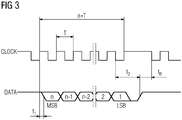
- a clock signal with a period T and a data word length n is sent to an encoder 30, which responds with a data signal and accordingly first sends the first bit (LSB) and then the following bits up to the last bit n (MSB) .
- T1 is the output delay time in encoder 20.
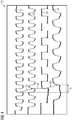
- a first signal course 51 is the signal course at the first connection (clock signal)
- a second signal course 52 is the signal course at the encoder input (clock)
- a third signal course 53 is the signal course at the encoder output (data)
- a fourth signal course 54 is the signal course at the second connection 12 of the input module 1 (data).
- a first delay time 61 can be seen between the first signal curve 51 and the second signal curve 52, which is caused by a simple line delay.
- a second delay time 62 can be seen between the second signal profile 52 and the third signal profile 53, which corresponds to the response time of the transmitter 30, but which is relatively short compared to the line transit time.
- a third delay time 63 is shown between the third signal profile 53 and the fourth signal profile 54, which now also contains the second line delay time.
- a signal propagation time t d results accordingly, starting from the rising edge of the first signal curve 51 and the incoming rising edge of the fourth signal curve 54.
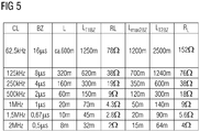
- FIG 5 is an example of the relationship between a clock frequency CL, the bit times BZ, the line length l, a theoretical maximum line length l with a maximum of 1 bit time Lt1BZ, a line resistance LR, a maximum line length l with a maximum of 2 bit times Lmax2BZ, a theoretical maximum line length with a maximum of 2 bit times LT2BZ and again the line resistance shown. It can clearly be seen in the second line with 125 kHz how a previously achieved length of 120 m with 2 bit times has increased to approx. 600 m.
Abstract
Die Erfindung betrifft ein Verfahren zum Betrieb einer Eingabebaugruppe (1) mit einer Synchron-Seriellen-Schnittstelle (SSI), wobei über einen ersten Anschluss (11) ein Taktsignal (CL) ausgegeben wird und über einen zweiten Anschluss (12) ein serieller Messwert (data) empfangen wird, wobei die Eingabebaugruppe (1) in einem Ermittlungsmodus (EM) und in einem Messmodus (MM) betrieben wird, wobei- in dem Ermittlungsmodus (EM) eine Signallaufzeit (t<sub>d</sub>) einer an die Anschlüsse (11,12) angeschlossenen Leitung (L) ermittelt wird und- in dem Messmodus (MM) die ermittelte Signallaufzeit (t<sub>d</sub>) bei der Messung folgendermaßen berücksichtigt wird, mit dem Aussenden einer ersten Taktflanke (20) des Taktsignals (CL) wird ein Zeitzähler (Z1) gestartet und wenn der Wert des Zeitzählers (Z1) den Wert der Signallaufzeit (t<sub>d</sub>) erreicht hat, wird der Messwert (data) am zweiten Anschluss (12) eingelesen.The invention relates to a method for operating an input module (1) with a synchronous serial interface (SSI), a clock signal (CL) being output via a first connection (11) and a serial measured value (12) being output via a second connection (12). data) is received, the input module (1) being operated in a determination mode (EM) and in a measurement mode (MM), with a signal transit time (t <sub> d </sub>) in the determination mode (EM) the connections (11,12) connected line (L) is determined and - in the measurement mode (MM) the determined signal propagation time (t <sub> d </sub>) is taken into account during the measurement as follows, with the transmission of a first clock edge ( 20) of the clock signal (CL), a time counter (Z1) is started and when the value of the time counter (Z1) has reached the value of the signal propagation time (t <sub> d </sub>), the measured value (data) is sent to the second connection (12) read.
Description
Die Erfindung betrifft ein Verfahren zum Betrieb einer Eingabebaugruppe mit einer Synchron-Seriellen-Schnittstelle, wobei über einen ersten Anschluss ein Taktsignal ausgegeben wird und über einen zweiten Anschluss ein serieller Messwert empfangen wird.The invention relates to a method for operating an input module with a synchronous serial interface, a clock signal being output via a first connection and a serial measured value being received via a second connection.
Ebenso betrifft die Erfindung eine Eingabebaugruppe mit einer Synchron-Seriellen-Schnittstelle umfassend einen ersten Anschluss, einen zweiten Anschluss, ein Sendemittel, ein Empfangsmittel, wobei das Sendemittel ausgestaltet ist, über den ersten Anschluss ein Taktsignal auszugeben, und das Empfangsmittel ausgestaltet ist, über den zweiten Anschluss einen seriellen Messwert zu empfangen.The invention also relates to an input module with a synchronous serial interface comprising a first connection, a second connection, a sending means, a receiving means, the sending means being configured to output a clock signal via the first connection, and the receiving means being configured via which second connection to receive a serial measurement value.
Eine Synchron-Serielle-Schnittstelle (SSI) ist eine Schnittstelle für z.B. Absolutwertgeber (beispielsweise Weg-Messsysteme). Sie ermöglicht es, durch eine serielle Datenübertragung eine Absolutinformation über beispielsweise eine Position zu erhalten. Eine Datenübertragung basiert auf einer RS422-Hardware (Sender/Empfänger), es wird eine Punkt-zu-Punkt-Verbindung aufgebaut. In einem Sensor/Geber wird ein Schieberegister permanent mit einem aktuellen Messwert geladen. Wenn ein Datenwert gelesen werden soll, gibt beispielsweise eine Eingabebaugruppe einen Takt auf eine Taktleitung aus. Mit einer ersten fallenden Flanke des Taktsignals, wird beispielsweise ein Monoflop im Sensor/Geber umgeschaltet, welches das Schieberegister vom parallelen Laden eines Messwertes in eine serielle Ausgabe umschaltet. Bei jeder folgenden steigenden Taktflanke des Taktsignals wird jetzt ein Datenbit ausgegeben. Wenn das niederwertigste Bit empfangen wurde, wird der Takt gestoppt. Das Monoflop, das von den Taktpulsen immer nachgetriggert wurde, fällt nach Ablauf der Schaltzeit wieder in den Grundzustand und erlaubt wieder die Übernahme der Messwerte in das Schieberegister.A synchronous serial interface (SSI) is an interface for, for example, absolute value encoders (for example position measuring systems). It makes it possible to obtain absolute information about a position, for example, through serial data transmission. Data transmission is based on RS422 hardware (transmitter / receiver), a point-to-point connection is established. A shift register in a sensor / transmitter is permanently loaded with a current measured value. If a data value is to be read, an input module outputs a clock on a clock line, for example. With a first falling edge of the clock signal, a monoflop in the sensor / transmitter is switched over, for example, which switches the shift register from parallel loading of a measured value to a serial output. A data bit is now output with each subsequent rising edge of the clock signal. When the least significant bit has been received, the clock is stopped. The monoflop, which was always retriggered by the clock pulses, falls after the Switching time back to the basic state and allows the measured values to be transferred to the shift register again.
Derartige zuvor erklärte Synchron-Serielle-Schnittstelle (SSI) werden beispielsweise in Automatisierungsbaugruppen zur Positionserfassung eingesetzt. Nach heutigem Kenntnisstand ist beispielsweise bei der Absolutwert-Erfassungsbaugruppe SIMATIC SM338 für das ET200 System eine maximale Kabellänge zwischen Baugruppe und Geber von 320 Metern freigegeben, bei welcher für einen Takt von 125 kHz noch eine sichere Datenübertragung gewährleistet ist. Bei höheren SSI-Taktraten reduzieren sich die maximal möglichen Kabellängen, beispielsweise auf 8 Meter bei 2 MHz, 10 Meter bei 1,5 MHz, 20 Meter bei 1 MHz, 60 Meter bei 500 KHz, 160 Meter bei 250 KHz und entsprechend 320 Meter bei 125 KHz.Such synchronous serial interfaces (SSI) explained above are used, for example, in automation assemblies for position detection. As far as we know today, a maximum cable length of 320 meters has been approved for the SIMATIC SM338 absolute value acquisition module for the ET200 system, with which a safe data transmission is still guaranteed for a cycle of 125 kHz. At higher SSI clock rates, the maximum possible cable lengths are reduced, for example to 8 meters at 2 MHz, 10 meters at 1.5 MHz, 20 meters at 1 MHz, 60 meters at 500 KHz, 160 meters at 250 KHz and correspondingly 320 meters at 125 KHz.
Es ist Aufgabe der vorliegenden Erfindung ein Verfahren und eine Baugruppe mit einer SST-Schnittstelle bereitzustellen, bei welchem es beispielsweise möglich ist, die Kabellänge zu erhöhen und eine sichere Datenübertragung dennoch zu gewährleisten.It is the object of the present invention to provide a method and a module with an SST interface in which it is possible, for example, to increase the cable length and still ensure reliable data transmission.
Für das eingangs genannte Verfahren wird die Aufgabe dadurch gelöst, dass die Eingabebaugruppe in einem Ermittlungsmodus und in einem Messmodus betrieben wird, wobei in dem Ermittlungsmodus eine Signallaufzeit einer an die Anschlüsse angeschlossene Leitung ermittelt wird und in dem Messmodus die ermittelte Signallaufzeit bei der Messung folgendermaßen berücksichtigt wird:
Mit dem Aussenden einer erste Taktflanke des Taktsignals wird ein Zeitzähler gestartet und wenn der Wert des Zeitzählers den Wert der Signallaufzeit erreicht hat, wird der Messwert am zweiten Anschluss eingelesen.For the method mentioned at the beginning, the object is achieved in that the input module is operated in a determination mode and in a measurement mode, with a signal propagation time of a line connected to the connections being determined in the determination mode and the determined signal propagation time being taken into account during the measurement in the measurement mode as follows becomes:
When a first clock edge of the clock signal is sent out, a time counter is started and when the value of the time counter has reached the value of the signal propagation time, the measured value is read in at the second connection.
Wenn in der Eingabebaugruppe die zeitliche Verzögerung zwischen einem ausgegebenen Signal einer Taktflanke und dem empfangenen Signal einer Datenflanke bekannt ist, so kann diese gemessene oder parametrierte Verzögerung beim Einlesen der SSI-Daten berücksichtigt werden, nämlich mit einer ausgegebenen steigenden Taktflanke wird eine Delay-Zeit bzw. ein Zeitzähler neu gestartet und nach Ablauf der Delay-Zeit kann das SSI-Datensignal eingelesen werden, dadurch ist eine deutliche Vergrößerung der zulässigen Leitungslänge bei gleichbleibender Taktfrequenz möglich. Das bedeutet, durch eine Entkopplung der eingelesenen Daten vom ausgegebenen Takt kann man die heute mögliche maximale Leitungsverzögerung von einem SSI-Takt auf zwei SSI-Takte (oder auch mehr) vergrößern. Als SSI-Takt bezeichnet man auch die maximale Bit-Zeit. Eine Bit-Zeit ist die Zeit, die vergeht, bis von einem ausgegebenen Takt ein erstes Datensignal, empfangen.If the time delay between an output signal of a clock edge and the received signal of a data edge is known in the input module, then this can measured or parameterized delay when reading in the SSI data are taken into account, namely with an output rising clock edge a delay time or a timer is restarted and after the delay time has elapsed, the SSI data signal can be read in, which is a significant increase the permissible cable length with constant clock frequency possible. This means that by decoupling the read-in data from the output clock, the maximum line delay possible today can be increased from one SSI clock to two SSI clocks (or more). The maximum bit time is also referred to as the SSI clock. A bit time is the time that elapses before a first data signal is received from an output clock.
Eine Ermittlung der Signallaufzeit kann auf unterschiedliche Art erfolgen, als vorteilhaft hat sich folgendes herausgestellt:
- a) Zur Ermittlung der Signallaufzeit sendet die Baugruppe ein Taktsignal mit einem SSI-Takt mit einer kleineren Frequenz als später im Messmodus verwendet wird und wenn die erste gesendete steigende Taktflanke wieder am zweiten Anschluss ankommt, wird die Signallaufzeit ermittelt oder
- b) Ein an die Anschlüsse angeschlossener Geber wird auf einem bekannten Test-Wert eingestellt und wenn dieser bekannte Test-Wert wieder am zweiten Anschluss ankommt, wird die Signallaufzeit ermittelt oder
- c) Ein Anwender parametriert die Baugruppe mit der angeschlossenen Leitungslänge der Leitung und ein Berechnungsmittel errechnet die Signallaufzeit.
- a) To determine the signal delay, the module sends a clock signal with an SSI clock with a lower frequency than will be used later in the measurement mode and when the first rising clock edge that is sent arrives again at the second connection, the signal delay is determined or
- b) A transmitter connected to the connections is set to a known test value and when this known test value arrives again at the second connection, the signal propagation time is determined or
- c) A user parameterizes the module with the connected line length of the line and a calculation device calculates the signal propagation time.
So kann beispielsweise ein Anwender einer industriellen Anlage die Leitungslänge zwischen der Eingabebaugruppe und einem Geber in die Eingabebaugruppe eingeben und die Eingabebaugruppe errechnet automatisch die passende Verzögerungszeit und kann sich darüber hinaus auch noch bei Veränderung der Leitungslängen automatisch anpassen.For example, a user of an industrial system can enter the cable length between the input module and an encoder in the input module and the input module automatically calculates the appropriate delay time and can also adapt automatically when the cable lengths change.
Auch wird es als vorteilhaft angesehen, wenn die Eingabebaugruppe nach dem Einschalten automatisch in den Ermittlungsmodus schaltet und eine Signallaufzeit-Messung durchführt.It is also considered advantageous if the input module automatically switches to the determination mode after being switched on and carries out a signal propagation time measurement.
Bei der eingangs genannten Eingabebaugruppe wird die eingangs genannte Aufgabe dadurch gelöst, dass ein Modus-Schaltmittel vorhanden ist, welches ausgestaltet ist, in einem Ermittlungsmodus ein Ermittlungsmittel zu aktivieren und in einem Messmodus ein Einlesemittel zu aktivieren, wobei das Ermittlungsmittel ausgestaltet ist, eine Signallaufzeit einer an die Anschlüsse angeschlossene Leitung zu ermitteln und das Einlese-Mittel ausgestaltet ist, den Messwert einzulesen wenn ein Zeitzähler den Wert der Signallaufzeit erreicht hat, wobei der Zeitzähler nach dem Aussenden einer ersten Taktflanke des Taktsignals gestartet wird.In the case of the input module mentioned at the beginning, the object mentioned at the beginning is achieved in that a mode switching means is present which is designed to activate a determination means in a determination mode and to activate a reading means in a measurement mode, the determination means being designed to provide a signal transit time to determine the line connected to the connections and the read-in means is designed to read in the measured value when a time counter has reached the value of the signal transit time, the time counter being started after a first clock edge of the clock signal has been sent out.
Durch die Entkopplung der eingelesenen Daten von dem ausgegebenen Takt kann die Signallaufzeit aufgrund einer maximalen Leitungslänge länger als bisher sein. In einer ersten Alternative ist das Ermittlungsmittel zusammen mit dem Schaltmittel und dem Empfangsmittel folgendermaßen ausgestaltet:
Zur Ermittlung der Signallaufzeit sendet die Baugruppe ein Taktsignal mit einem SSI-Takt mit einer kleineren Frequenz als später im Messmodus verwendet wird und wenn die erste gesendete steigende Taktflanke wieder am zweiten Anschluss ankommt wird die Signallaufzeit ermittelt.By decoupling the read-in data from the clock output, the signal propagation time can be longer than before due to the maximum cable length. In a first alternative, the determination means, together with the switching means and the receiving means, is designed as follows:
To determine the signal delay, the module sends a clock signal with an SSI clock with a lower frequency than will be used later in the measurement mode and when the first rising clock edge that is sent arrives at the second connection, the signal delay is determined.
Eine zweite alternative Ausgestaltung sieht vor, das Ermittlungsmittel zusammen mit dem Sendemittel und dem Empfangsmittel folgendermaßen auszugestalten, zur Ermittlung der Signallaufzeit wird ein an die Anschlüsse angeschlossener Geber auf einen bekannten Test-Wert eingestellt und wenn dieser bekannte Test-Wert aufgrund der am Geber ankommenden Taktflanke vom Geber gesendet wird und der Test-Wert vom Empfangsmittel gelesen wird, kann die Signallaufzeit ermittelt werden.A second alternative embodiment provides for the determination means to be configured together with the sending means and the receiving means as follows: to determine the signal propagation time, a transmitter connected to the connections is set to a known test value and if this known test value is due to the clock edge arriving at the transmitter from Transmitter is sent and the test value is read by the receiving means, the signal propagation time can be determined.
Eine dritte alternative Ausgestaltung sieht vor, dass ein Berechnungsmittel vorhanden ist, welches ausgestaltet ist, dass ein Anwender eine Leitungslänge einer zum Geber führenden Leitung parametriert und die Signallaufzeit aus der Länge in der Baugruppe automatisch errechnet wird.A third alternative embodiment provides that a calculation means is present which is designed so that a user parameterizes a line length of a line leading to the encoder and the signal propagation time is automatically calculated from the length in the assembly.
Die Zeichnung zeigt ein Ausführungsbeispiel der Erfindung. Dabei zeigt die
- FIG 1
- eine prinzipielle Anordnung von Eingabebaugruppe und Geber,
- FIG 2
- ein detailliert dargestelltes Blockschaltbild der Eingabebaugruppe,
- FIG 3
- eine Prinzipdarstellung der Datenübertragung zwischen Eingabebaugruppe und Geber,
- FIG 4
- Signalverläufe an der Eingabebaugruppe und dem Geber und
- FIG 5
- eine Tabelle, welche den Zusammenhang zwischen den benutzten SSI-Taktfrequenzen und den aktuell unterstützten Leitungslängen und der erfindungsgemäß vergrößerten Leitungslänge darstellt.
- FIG 1
- a basic arrangement of the input module and encoder,
- FIG 2
- a detailed block diagram of the input module,
- FIG 3
- a schematic diagram of the data transmission between input module and encoder,
- FIG 4
- Signal curves on the input module and the encoder and
- FIG 5
- a table which shows the relationship between the SSI clock frequencies used and the line lengths currently supported and the line length increased according to the invention.
Gemäß
Mit der
Ein Modus-Schaltmittel 40 ermöglicht es, den ausgegebenen Takt CL und das Einlesen des Messwertes data voneinander zu entkoppeln. Dazu ist das Modus-Schaltmittel 40 ausgestaltet, in einem Ermittlungsmodus EM ein Ermittlungsmittel 41 zu aktivieren und in einem Messmodus MM ein Einlese-Mittel 42 zu aktivieren. Das Ermittlungsmittel 41 ist ausgestaltet, eine Signallaufzeit td der an die Anschlüsse 12 angeschlossenen Leitung L zu ermitteln und das Einlese-Mittel 42 ist ausgestaltet, den Messwert data einzulesen, wenn ein Zeitzähler Z1 den Wert der Signallaufzeit td erreicht hat. Der Zeitzähler Z1 wird dazu mit dem Aussenden einer ersten Taktflanke 20 des Taktsignals CL gestartet. Für das Starten ist das Sendemittel 43 über eine Triggerleitung 45 mit dem Zeitzähler Z1 verbunden. Der Zeitzähler Z1 ist wiederum mit einer Enableleitung 46 mit dem Einlesemittel 42 verbunden, um bei Ablauf des Zeitzähler Z1 dem Einlesemittel 42 mitzuteilen, dass es jetzt gültige Daten einlesen kann.A mode switching means 40 enables the output clock CL and the reading in of the measured value data to be decoupled from one another. For this purpose, the mode switching means 40 is designed to activate a determination means 41 in a determination mode EM and to activate a read-in means 42 in a measurement mode MM. The determination means 41 is designed to determine a signal transit time t d of the line L connected to the
Der Zeitzähler Z1 ist mit dem Ermittlungsmittel 41 verbunden und holt sich aus einen Speicher des Ermittlungsmittels 41 die ermittelte Signallaufzeit td zum Vergleich des aktuellen Wertes des Zeitzählers Z1 mit der Signallaufzeit td.The time counter Z1 is connected to the determination means 41 and fetches the determined signal transit time t d from a memory of the determination means 41 to compare the current value of the time counter Z1 with the signal transit time t d .
Auch ist es möglich anstatt eines automatischen Ermittelns über das Ermittlungsmittel 41 die Baugruppe zu parametrieren, dazu wird in einem Speicher 48 für die Leitungslänge l die Leitungslänge l der Leitung L hinterlegt und ein Berechnungsmittel 47 errechnet automatisch die Signallaufzeit td.It is also possible to parameterize the module instead of an automatic determination via the determination means 41, for this purpose the line length l of the line L is stored in a
Gemäß
Mit der
Zwischen dem ersten Signalverlauf 51 und dem zweiten Signalverlauf 52 ist eine erste Verzögerungszeit 61 zu erkennen, welche durch eine einfache Leitungslaufzeit hervorgerufen wird. Zwischen dem zweiten Signalverlauf 52 und dem dritten Signalverlauf 53 ist eine zweite Verzögerungszeit 62 zu erkennen, welche der Reaktionszeit des Gebers 30 entspricht, diese aber im Vergleich zur Leitungslaufzeit relativ gering ausfällt. Zwischen dem dritten Signalverlauf 53 und dem vierten Signalverlauf 54 ist eine dritte Verzögerungszeit 63 dargestellt, welche nun auch die zweite Leitungslaufzeit enthält. Dementsprechend ergibt sich eine Signallaufzeit td, ausgehend von der steigenden Flanke des ersten Signalverlaufs 51 und der ankommenden steigenden Flanke des vierten Signalverlaufs 54.A
Mit der
Claims (7)
dadurch gekennzeichnet, dass die Eingabebaugruppe (1) in einem Ermittlungsmodus (EM) und in einem Messmodus (MM) betrieben wird, wobei
characterized in that the input module (1) is operated in a determination mode (EM) and in a measurement mode (MM), wherein
einen ersten Anschluss (11),
einen zweiten Anschluss (12),
ein Sendemittel (43),
ein Empfangsmittel (44),
wobei das Sendemittel (43) ausgestaltet ist über den ersten Anschluss (11) ein Taktsignal (CL) auszugeben, und
das Empfangsmittel (44) ausgestaltet ist über den zweiten Anschluss (12) einen seriellen Messwert (data) zu empfangen,
gekennzeichnet durch ein
Modus-Schaltmittel (40), welches ausgestaltet ist in einem Ermittlungsmodus (EM) ein Ermittlungsmittel (41) zu aktivieren und in einem Messmodus (MM) ein Einlese-Mittel (42) zu aktivieren, wobei das
a first connection (11),
a second connection (12),
a sending means (43),
a receiving means (44),
wherein the transmission means (43) is configured to output a clock signal (CL) via the first connection (11), and
the receiving means (44) is designed to receive a serial measured value (data) via the second connection (12),
marked by a
Mode switching means (40) which is designed to activate a determination means (41) in a determination mode (EM) and to activate a read-in means (42) in a measurement mode (MM), the
Priority Applications (1)
| Application Number | Priority Date | Filing Date | Title |
|---|---|---|---|
| EP19187714.1A EP3771136A1 (en) | 2019-07-23 | 2019-07-23 | Installed module and method for operating an installed module |
Applications Claiming Priority (1)
| Application Number | Priority Date | Filing Date | Title |
|---|---|---|---|
| EP19187714.1A EP3771136A1 (en) | 2019-07-23 | 2019-07-23 | Installed module and method for operating an installed module |
Publications (1)
| Publication Number | Publication Date |
|---|---|
| EP3771136A1 true EP3771136A1 (en) | 2021-01-27 |
Family
ID=67438485
Family Applications (1)
| Application Number | Title | Priority Date | Filing Date |
|---|---|---|---|
| EP19187714.1A Withdrawn EP3771136A1 (en) | 2019-07-23 | 2019-07-23 | Installed module and method for operating an installed module |
Country Status (1)
| Country | Link |
|---|---|
| EP (1) | EP3771136A1 (en) |
Citations (2)
| Publication number | Priority date | Publication date | Assignee | Title |
|---|---|---|---|---|
| WO2002095513A2 (en) * | 2001-05-23 | 2002-11-28 | Dr. Johannes Heidenhain Gmbh | Method for operating a position measuring device |
| WO2003085466A2 (en) * | 2002-03-29 | 2003-10-16 | Siemens Energy & Automation, Inc. | Device, system and method for compensating for isolation and cable delays in an ssi encoder interface circuit |
-
2019
- 2019-07-23 EP EP19187714.1A patent/EP3771136A1/en not_active Withdrawn
Patent Citations (2)
| Publication number | Priority date | Publication date | Assignee | Title |
|---|---|---|---|---|
| WO2002095513A2 (en) * | 2001-05-23 | 2002-11-28 | Dr. Johannes Heidenhain Gmbh | Method for operating a position measuring device |
| WO2003085466A2 (en) * | 2002-03-29 | 2003-10-16 | Siemens Energy & Automation, Inc. | Device, system and method for compensating for isolation and cable delays in an ssi encoder interface circuit |
Non-Patent Citations (1)
| Title |
|---|
| HEIDENHAIN GMBH: "EnDat 2.2 - Bidirectional Interface for Position Encoders", INTERNET CITATION, 30 November 2008 (2008-11-30), pages 1 - 20, XP002659570, Retrieved from the Internet <URL:http://www.heidenhain.in/fileadmin/pdb/media/img/383_942-25_EnDat_2-2_en.pdf> [retrieved on 20110920] * |
Similar Documents
| Publication | Publication Date | Title |
|---|---|---|
| EP2289201B1 (en) | Device and method for the serial data transmission between a position measuring device and a control unit | |
| EP2718677B1 (en) | High precision synchronized measured value acquisition | |
| WO2015096933A1 (en) | Measurement transducer having a monitoring function | |
| WO2012079992A1 (en) | Method for monitoring the operation of a field device | |
| EP2021736B1 (en) | Measuring transducer | |
| DE10014671B4 (en) | Apparatus and method for detecting data communication properties | |
| DE102008054887A1 (en) | Device and method for automated recognition of an interface | |
| WO2013020529A1 (en) | Measured value transmitting device | |
| DE102005055429B4 (en) | Method and device for diagnosing a bus system with a number of bus subscribers | |
| DE19726539C2 (en) | Method and circuit arrangement for localizing a short circuit or cable break in a bus system | |
| CN101202440B (en) | Protection circuit of relay right action and method for preventing error action of relay | |
| DE102014212288A1 (en) | Device and method for generating a trigger signal in a position measuring device and position measuring device for this purpose | |
| EP3771136A1 (en) | Installed module and method for operating an installed module | |
| EP2079176B1 (en) | Communication device and method of data transfer | |
| EP0354214B1 (en) | Process for determining the electrical duration of signal paths | |
| DE2842603C3 (en) | Interface between a maintenance processor and a plurality of individually tested functional units of a data processing system | |
| EP4029185B1 (en) | Device and method for synchronous-serial data transmission | |
| DE102009026641A1 (en) | Method for operating a data transmission system, data transmission system and computer program product | |
| EP2157438A1 (en) | Method for operating an end device in a communication system and corresponding end device | |
| EP4018600B1 (en) | Method for recognising the position of a bus subscriber | |
| DE4005087C1 (en) | Connector unit for domestic power installation - has adaptor for specific function allowing data transmission via bus and data lines | |
| DE10156043B4 (en) | Position-determining device | |
| EP1153339B1 (en) | Method and device for function selection of a control unit | |
| DE10048467B4 (en) | Jitter generation for measuring the remaining jitter tolerance during operation on a transmission link with a high data rate | |
| AT521939B1 (en) | Method and measuring device for determining a latency period |
Legal Events
| Date | Code | Title | Description |
|---|---|---|---|
| PUAI | Public reference made under article 153(3) epc to a published international application that has entered the european phase |
Free format text: ORIGINAL CODE: 0009012 |
|
| STAA | Information on the status of an ep patent application or granted ep patent |
Free format text: STATUS: THE APPLICATION HAS BEEN PUBLISHED |
|
| AK | Designated contracting states |
Kind code of ref document: A1 Designated state(s): AL AT BE BG CH CY CZ DE DK EE ES FI FR GB GR HR HU IE IS IT LI LT LU LV MC MK MT NL NO PL PT RO RS SE SI SK SM TR |
|
| AX | Request for extension of the european patent |
Extension state: BA ME |
|
| STAA | Information on the status of an ep patent application or granted ep patent |
Free format text: STATUS: THE APPLICATION IS DEEMED TO BE WITHDRAWN |
|
| 18D | Application deemed to be withdrawn |
Effective date: 20210728 |