JP4227323B2 - Slot machine - Google Patents
Slot machine Download PDFInfo
- Publication number
- JP4227323B2 JP4227323B2 JP2001321617A JP2001321617A JP4227323B2 JP 4227323 B2 JP4227323 B2 JP 4227323B2 JP 2001321617 A JP2001321617 A JP 2001321617A JP 2001321617 A JP2001321617 A JP 2001321617A JP 4227323 B2 JP4227323 B2 JP 4227323B2
- Authority
- JP
- Japan
- Prior art keywords
- phase
- excitation
- reel
- stop
- control
- Prior art date
- Legal status (The legal status is an assumption and is not a legal conclusion. Google has not performed a legal analysis and makes no representation as to the accuracy of the status listed.)
- Expired - Lifetime
Links
Images


Landscapes
- Slot Machines And Peripheral Devices (AREA)
Description
【0001】
【発明の属する技術分野】
本発明は、スロットマシンに関し、詳しくは複数の識別情報が配列されたリールが設けられた可変表示装置を有するスロットマシンに関する。
【0002】
【従来の技術】
この種の一般的なスロットマシンでは、ステッピングモータによりリールが駆動される。特に、スロットマシンでは、目標の識別情報でリールを正確に停止させなければならないため、リールを停止させる条件が成立した場合、たとえば、ステッピングモータの隣り合う2つの励磁相を同時に励磁して、リールを急停止させる必要がある。
【0003】
ところが、このように2つの励磁相を同時に励磁してリールに急制動をかけた場合、ステッピングモータの過渡応答の影響によって、リールが停止する際の振動を十分に抑えることができず、停止時にリールが “ブルブル”と振動して見苦しいという問題があった。
【0004】
そのため、従来より、停止制御方式としては、ステッピングモータの全相を同時に励磁してリールを停止させる全相励磁方式が採用されていた。この全相励磁方式は、詳しくは、以下の方法によってステッピングモータの駆動を停止させるものである。
【0005】
たとえば、励磁相としてφ1相からφ4相の4相を有するステッピングモータにおいて、φ1相を正規に流れる電流と、当該φ1相と対向するφ3相を正規に流れる同一レベルの電流とは、コア周辺を流れる電流として逆方向に流れる。したがって、異なる磁界の発生によりトルクを発生しない。しかしながら、ステッピングモータの回転中は誘導電圧によって逆起電力が生じ、たとえば、φ1相、φ3相に流れる電流の差分のトルクが発生する。このため、対向するφ1相、φ3相を励磁すると、リールの回転にブレーキがかかることになる。この現象は、対向するφ2相、φ4相を励磁した場合も同様に発生する。このため、全相を励磁した場合、その全相励磁を開始してからステッピングモータが減速しつつ所定ステップ数だけ駆動した(滑った)後、ディテントトルクの安定点にステッピングモータが振動することなく完全停止する。
【0006】
【発明が解決しようとする課題】
全相励磁方式では、全相励磁を開始した時点からステッピングモータが“滑る”ステップ数を考慮して、停止制御を行なう必要がある。しかしながら、全相励磁方式でリールを停止させると、リールの速度、リールイナーシャ、モータ摩擦、モータディテントトルクなど、メカニカルな要素により停止位置にばらつきが出てしまう。また、予定停止位置よりも進んだ位置で停止した場合、次回、リールを回転させる際に最初に励磁された励磁相(スタート相)へステッピングモータのロータが一旦、引込まれるという現象が発生し、見た目に不自然な動作が発生するおそれがあった。
【0007】
本発明は係る実情に鑑み考え出されたものであり、その目的は、リールの停止制御の精度を向上し、かつ、リールの停止時の振動を抑えることが可能なスロットマシンを提供することである。
【0008】
【課題を解決するための手段の具体例およびその効果】
(1) 複数種類の識別情報が設けられたリールを有する可変表示装置(たとえば、リール4)を備えたスロットマシンであって、
前記リールを回転駆動するステッピングモータ(たとえば、リールモータ402)と、
該ステッピングモータを制御する制御手段(たとえば、遊技制御基板100)とを含み、
該制御手段は、前記ステッピングモータの複数の励磁相の励磁パターンを所定期間毎に切換えて前記リールを回転させた後、回転中のリールを停止させる条件が成立したときに(たとえば、ストップ信号の入力を受けて選択された停止図柄が、停止位置に停止できる位置に到来した)、
前記複数の励磁相(たとえば、φ1〜φ4)のうち、前記ステッピングモータのロータの目標停止角度位置に対応する停止励磁相よりも前記ロータの回転方向に対して2つ手前および1つ手前に夫々位置する第1励磁相および第2励磁相を併せて励磁する2相励磁制御(たとえば、φ1、φ2の励磁)を前記所定期間よりも長い期間実行して前記ロータの回転に急制動をかけた後(たとえば、SM3)、
前記停止励磁相、当該停止励磁相と隣合う前記第2励磁相および第4励磁相を併せて励磁する3相励磁制御(たとえば、φ2、φ3、φ4の励磁)を実行することにより(たとえば、SM5)、前記ロータを前記停止励磁相で停止させることを特徴とする。
【0009】
上記の構成によれば、前記2相励磁制御によってロータの回転が急速に制動されつつオーバーシュートする。このため、オーバーシュート先にロータの目標停止角度位置を設定しておれば、前記2相励磁制御によって、ロータが回転速度を急速に減じながら前記目標停止角度位置へと誘導されるようになる。その後、さらに、前記3相励磁制御によって、前記第2励磁相および前記第4励磁相によるブレーキを得ながら、勢いを弱められたロータが前記停止励磁相のホールディングトルク安定点において停止する。このため、目標停止角度位置を前記停止励磁相のホールディングトルク安定点に設定しておれば、前記第2励磁制御および前記第3励磁制御によって、正確かつ振動を生じさせることなく、ロータを目標停止角度位置で停止させることができる。その結果、リールの停止制御の精度を向上し、かつ、リールの停止時の振動を抑えることが可能となる。
【0010】
(2) 前記制御手段は、1−2相励磁方式で前記ステッピングモータを制御して前記リールを回転駆動させる(図5参照)ことを特徴とする。
【0011】
上記の構成によれば、ステップ角を細かくすることができ、細やかな制御を行なうことが可能になる。また、そのため、安定かつスムースにリールを停止させることができる。
【0012】
(3) 前記制御手段は、回転中のリールを停止させる条件が成立したときに(たとえば、ストップ信号の入力を受けて選択された停止図柄が、停止位置に停止できる位置に到来した)、1−2相励磁方式において1相励磁から2相励磁に切換わるタイミングに合せて、前記リールを停止させるための前記2相励磁制御を開始する(たとえば、SM2、SM3)ことを特徴とする。
【0013】
上記の構成によれば、1−2相励磁方式において1相励磁から2相励磁に切換わるタイミングを利用してスムースかつ容易に前記2相励磁制御に移行できる。
【0014】
(4) 前記制御手段は、前記ロータの停止状態を安定させるための予め定めた時間が経過したか否かを判定する判定手段(たとえば、T2)を含み、
前記制御手段は、前記判定手段により前記時間が経過した判定されるまで、前記3相励磁制御を継続する(たとえば、SM5、SM6)ことを特徴とする。
【0015】
上記の構成によれば、リールを確実に停止した状態にすることができる。
(5) 前記制御手段は、前記3相励磁制御を実行した後、前記停止励磁相の励磁状態を維持しつつ前記第2励磁相および前記第4励磁相を消磁する(たとえば、SM7)ことを特徴とする。
【0016】
上記の構成によれば、前記3相励磁制御を実行した後、前記停止励磁相の励磁状態を維持しつつ前記第2励磁相および前記第4励磁相を消磁するため、前記第2励磁相および前記第4励磁相が不必要に励磁されることがなく、モータ発熱を抑えることができる。また、前記停止励磁相については、その励磁状態が維持されるため、前記停止励磁相のホールディングトルク安定点で停止させたロータが、ディテントトルク安定点へと移動してしまうことがない。
【0017】
(6) 前記ステッピングモータの総ステップ数は、前記リールに配列された識別情報の総数の整数倍(たとえば、図4において、168ステップ:21図柄×8ステップ)であることを特徴とする。
【0018】
上記の構成によれば、前記ステッピングモータの総ステップ数は、前記リールに配列された識別情報の総数の整数倍であるため、リールにおける各識別情報に対して、前記ステッピングモータのステップ数を均等に割当てることができる。このため、たとえば、総ステップ数を1リールの識別情報総数で除した余り分のステップをプログラム上、リールの最終識別情報と先頭識別情報との間に割当てて制御する必要がなく、制御プログラムが複雑化しない。
【0019】
【発明の実施の形態】
以下に本発明の実施の形態を図面に基づいて詳細に説明する。
【0020】
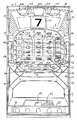
図1は、スロットマシン1の全体正面図である。スロットマシン1は、本体に対して前面扉2が開放可能に取り付けられている。前面扉2は、施錠装置53の鍵穴に挿入した所定のキーを時計回り方向に回動操作することにより開放させることが可能になる。
【0021】
前面扉2下部の左右には、略三角形状の右下部遊技効果ランプ部37、左下部遊技効果ランプ部38が設けられている。また、前面扉2上部の左右にはスピーカカバー58が設けられ、スロットマシン1の下方には下部スピーカ部59が設けられている。
【0022】
スピーカカバー58、右下部遊技効果ランプ部37、および左下部遊技効果ランプ部38によって囲まれる領域部分には、上部前面飾り枠8が設けられており、上部前面飾り枠8の下方には、下部前面飾り枠9が設けられている。
【0023】
上部前面飾り枠8は、遊技効果ランプ部30a〜30eおよび入賞図柄説明表示パネル5が設けられた上段部分と、遊技パネル6や各種表示部が設けられた略楕円型の中段部分と、遊技パネル6の下部から前面側に突出して形成され、メダル投入部51や各種操作ボタン43〜46、41L,41C,41R、スタートレバー42等が設けられた下段部分とからなる。下部前面飾り枠9には、スロットマシンの機種名称等が描かれたタイトルパネル7が設けられている。
【0024】
入賞図柄説明表示パネル5の略中央部分には演出用の液晶表示器50が設けられている。下部前面飾り枠9の下方には、遊技媒体の一例となるメダルが払出されるメダル払出穴54と前述した下部スピーカ部59とが形成されている。メダル払出穴54の下方には、灰皿56が形成されたメダル受け皿55が取付けられている。
【0025】
上部前面飾り枠8の遊技パネル6の周囲には、右斜め上部遊技効果ランプ部33と、左斜め上部遊技効果ランプ部34と、右中部遊技効果ランプ部31a,31bと、左中部遊技効果ランプ部32a,32bとが設けられている。また、スタートレバー42の左斜め下には左斜め下部遊技効果ランプ部36が設けられ、メダル詰まり解除ボタン46の右斜め下には右斜め下部遊技効果ランプ部35が設けられている。
【0026】
遊技パネル6には、スロットマシン1の本体側に設けられた左リール4L,中リール4C,右リール4Rを透視可能な透視窓40と、透視窓40の上方に位置する小役告知表示部24,25,26と、透視窓40の左側に位置する1枚賭け表示部21、2枚賭け表示部22a,22b、および3枚賭け表示部23a,23bと、透視窓40の右側に位置するゲームオーバー表示部14、リプレイ表示部15、ウエイト表示部16、スタート表示部17、および投入指示表示部(インサートメダル表示部ともいう。)18と、透視窓40の下側に位置するクレジット表示部11、ゲーム回数表示部12、およびペイアウト表示部13とが設けられている。
【0027】
クレジット表示部11、ゲーム回数表示部12、およびペイアウト表示部13は、LED(Light Emitting Diode)が内蔵された7セグメント表示器により構成されている。
【0028】
1枚賭け表示部21、2枚賭け表示部22a,22b、および3枚賭け表示部23a,23bは、遊技者がゲームに賭けた賭数を表示する。各賭け表示部は、図示のように透視窓40に描かれた5つの入賞ラインのいずれかと対応しており、賭数に応じた有効な入賞ラインを識別可能に報知する有効ライン表示部と兼用されている。
【0029】
小役告知表示部24,25,26には、各々異なる種類の入賞図柄が1つずつ描かれている。具体的には、小役告知表示部24には「白7」図柄が、小役告知表示部25には「模様付7」図柄が、小役告知表示部26には「BAR」図柄が描かれている。これらの小役告知表示部24〜26は、所定の小役入賞を発生させることがスロットマシンの制御部により許容されていること、すなわち、所定の小役入賞が内部当選していることを、その小役入賞に対応する入賞図柄を点灯させることによって告知するための表示部である。
【0030】
ゲームオーバー表示部14は、ビッグボーナスが終了することにより打止状態となった場合、および何らかのエラーが発生して遊技を進行させることができない状態となった場合に点灯する。リプレイ表示部15は、リプレイ入賞が発生した場合に点灯する。スタート表示部17は、賭数が設定されることによりスタート操作をすることが可能な状態となった場合に点灯し、有効なスタート操作が検出されることにより消灯する。投入指示表示部18は、メダルを受付可能な状態である場合に点滅し、最大の賭数が設定され、かつ、クレジット数が上限数に至った場合、ゲームが開始された場合等に消灯する。
【0031】
ウエイト表示部16は、ウエイトタイム中にスタート操作が検出された場合に点灯し、ウエイトタイムが経過した後に消灯する。ウエイトタイムは、ゲームがあまりに早く進行し過ぎてしまうことを規制するためにスロットマシンに設定された、ゲーム進行規制期間である。
【0032】
クレジット表示部11は、クレジット数を表示する。クレジットとは、遊技者所有の有価価値としてスロットマシン1側で記憶されているメダル数である。このクレジットは、スロットマシン1へのメダルの投入、および払出しのある入賞の発生によって加算更新され、賭数を設定したり、精算操作に基づいてメダルを払出したりすることによって減算更新される。スロットマシン1は、最大、メダル50枚分の価値をクレジットとして記憶可能である。クレジット数が上限数(=50)に達した場合には、投入指示表示部18が消灯する。そして、記憶の上限を超えるクレジットの加算更新の要求が発生した場合には、その上限を超えるメダルがメダル払出穴54から払出される。
【0033】
ゲーム回数表示部12は、ビッグボーナス中のボーナス入賞状況や、レギュラーボーナス中の入賞回数等を表示する。ペイアウト表示部13は、1ゲーム中に発生した入賞に基づいて遊技者に付与されるクレジット数を1ゲーム毎に表示する。
【0034】
遊技パネル6の下部から前面側に突出して形成された部分の上面には、メダル投入口52が形成されたメダル投入部51と、精算ボタン45と、1枚BETボタン43と、MAXBETボタン44とが設けられている。
【0035】
1枚BETボタン43は、1クレジットを賭ける際に押圧するボタンである。MAXBETボタン44は、1ゲームにおいて許容される賭数の最大数(たとえばメダル3枚分)をクレジットに記憶されている範囲内でゲームに賭ける際に押圧するボタンである。精算ボタン45は、スロットマシン1に記憶されているクレジットに基づいて、メダル払出穴54からメダルの払出しを受ける際に押圧するボタンである。
【0036】
遊技パネル6の下部から前面側に突出して形成された部分の側面には、スタートレバー42と、左ストップボタン41L,中ストップボタン41C,右ストップボタン41Rと、メダル詰まり解除ボタン46とが設けられている。
【0037】
スタートレバー42は、ゲームを開始する際に操作するレバーである。賭数を設定した後、このスタートレバー42を操作することにより各リール4L,4C,4Rが一斉に回転し始める。なお、各リール4L,4C,4Rの間のリール手前側には、各リール間の隙間を塞ぐためのリール間塞ぎ部材57が設けられている。
【0038】
各ストップボタン41L,41C,41Rは、ゲームが開始した後、回転しているリールを停止させる際に操作するボタンである。メダル詰まり解除ボタン46は、メダル投入口52に投入したメダルがスロットマシン1の内部で詰まった場合、メダル詰まりを解消させる際に操作するボタンである。
【0039】
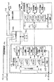
図2は、スロットマシンの制御基板を説明するためのブロック図である。
スロットマシン1に設けられた各種基板のうち、遊技制御基板100によって遊技の進行が制御され、演出制御基板101によって遊技の進行に応じた演出制御がなされる。遊技制御基板100は、リール中継基板103aおよび演出制御基板101と接続されている。さらに、遊技制御基板100は、リール中継基板103aを介して、外部出力基板104と接続されている。
【0040】
遊技制御基板100の制御部111から演出制御基板101へは、バッファ回路122を介して、演出制御用の各種のコマンドが出力される。演出制御基板101には、マイクロコンピュータからなる制御部131と、各スピーカ(図示省略)から音を出力させるためのスピーカ駆動回路136と、液晶表示器50を表示制御するための表示駆動回路137と、各種ランプを点灯あるいは点滅させるためのランプ駆動回路138と、バックアップ電源139と、バッファ回路141とが搭載されている。バッファ回路141は、遊技制御基板100の外部から内部へ信号が入力されることを阻止する不可逆性出力手段として機能する。
【0041】
制御部131は、CPU132と、制御プログラムを格納するROM134と、必要なデータの書込みおよび読出しができるRAM133と、I/Oポート135とを含む。
【0042】
遊技制御基板100に設けられた制御部111は、制御動作を所定の手順で実行することのできるCPU(Central Processing Unit)112と、CPU112の制御プログラムを格納するROM(Read Only Memory)114と、必要なデータの書込みおよび読出しができるRAM(Random Access Memory)113と、CPU112と外部回路との信号の整合性をとるためのI/Oポート115とを含む。
【0043】
また、遊技制御基板100には、電源投入時にCPU112にリセットパルスを与える初期リセット回路118と、CPU112にクロック信号を与えるクロック発生回路119と、クロック発生回路119からのクロック信号を分周して割込パルスを定期的にCPU112に与えるパルス分周回路(割込パルス発生回路)121と、一定範囲の乱数を高速で連続的に発生している乱数発生回路123と、乱数発生回路123から乱数をサンプリングするサンプリング回路124と、バッファ回路122と、各種スイッチからの信号が入力されるスイッチ回路116と、停電時にRAM113の記憶を保持させるためのバックアップ電源125と、モータ回路117とが設けられている。モータ回路117は、リール中継基板103aを介して、各リール4L,4C,4R別に設けられたリールモータ402と接続されている。
【0044】
制御部111は、スタートレバー42が操作されたことを示すスタート信号が入力された場合に、モータ回路117を介して、リールモータ402を駆動し、各リール4L,4C,4Rを一斉に回転開始させる。
【0045】
スタート信号は、スタートレバー42の操作を検出するスタートスイッチ420により、スイッチ回路116を介して制御部111に入力されるとともに、サンプリング回路124に入力される。
【0046】
サンプリング回路124は、スタートスイッチ420の検出信号が入力されたタイミングで、乱数発生回路123から1個の乱数をサンプリングし、その乱数をCPU112に引き渡す。CPU112は、そのサンプリングされた乱数と、ROM114内に格納されている入賞役別の入賞判定テーブルとを参照して、入賞の発生を許容するか否かを入賞役別に決定し、その決定結果をRAM114に記憶させる。これにより、スタート操作のタイミングで、入賞役の当選の有無が決定される。入賞の発生が許容されていることを、“内部当選している”という。いずれかの入賞役が内部当選した場合、その入賞役に対応する当選フラグがスロットマシン1の内部で設定される。
【0047】
制御部111は、ストップボタン41L,41C,41Rが操作されたことを示すストップ信号が入力されるか、若しくは、リールの回転開始から規定時間が経過した場合に、回転中のリールを停止させる停止制御を開始する。ストップ信号は、ストップボタン41L,41C,41Rの操作を検出するためにストップボタン別に設けられたストップスイッチ411L,411C,411Rにより、スイッチ回路116を介して制御部111に入力される。
【0048】
制御部111は、ストップ信号を検出した時点から予め定められた引込み可能範囲(たとえば、リール配列において5図柄以内)内にある図柄のいずれかを停止させる。たとえば、当選フラグが設定されたゲームでは、その当選フラグに対応する入賞役の当り図柄が引込み可能範囲にあれば、その当り図柄を停止させる。一方、当選フラグが設定されていないゲームでは、引込み可能範囲内の図柄のうち、入賞が発生しない図柄を停止図柄として選択して、その選択した図柄を停止させる。
【0049】
図3に、リールモータ402のブロック図を示す。リールモータ402は、たとえば、ハイブリッド(Hybrid)形ステッピングモータであり、ステ−タ402bと、これに対向するロータ402aとで構成されている。なお、ロータ402aは、図示を省略する多数の歯車状突極を有し、これに回転軸と同方向に磁化された永久磁石が組み込まれている。このリールモータ402は、モータ回路117からパルス信号を受け、ステータ402bの各相(たとえば、φ1〜φ4)が所定の順序に従って励磁されることにより、ロータ402aを回転させる。
【0050】
図4は、各リール4L,4C,4Rの展開図である。図において、「左」は左リール4Lの外周に描かれた図柄を示した図であり、「中」は中リール4Cの外周に描かれた図柄を示した図であり、「右」は右リール4Rの外周に描かれた図柄を示した図である。図示のように、各リール4L,4C,4Rには、図柄が21ずつ配列されている。また、各図柄に対してリールモータ408のステップ数が8ステップずつ均等に割当てられている。このため、リールモータ408の総ステップ数(1回転時に必要なパルス数)は168である。
【0051】
従来、リールモータの総ステップ数は、リールに配列された図柄数の整数倍に設定されていなかった。このため、従来、たとえば、総ステップ数を図柄総数で除した余り分のステップをプログラム上、リールの最終図柄と先頭図柄との間(図柄番号0の図柄と図柄番号20の図柄との間)に割当てて制御していた。その結果、制御プログラムが複雑化するという問題があった。
【0052】
本実際の形態では、リールモータのステップ数が図柄の配列数の整数倍のステップ数(168ステップ:21図柄×8ステップ)となっているために、制御プログラムが複雑化するという従来の問題が生じない。
【0053】
図5は、リールモータ402の制御方法を説明するためのタイミングチャートである。図において、φ1、φ2、φ3、φ4は、リールモータ402の各励磁相を示し、「ON」は励磁状態を、「OFF」は消磁状態を、各々示す。また、グラフAは、リールモータ402のロータの回転ステップ数の変位を示す。
【0054】
本発明のリールモータの停止制御の特徴は、次の通りである。すなわち、ストップ信号の入力を受けて選択された停止図柄が、停止位置に停止できる位置に到来することによって、回転中のリールを停止させる条件が成立した場合に、全励磁相のうち、隣合った2つの励磁相(たとえば、φ1とφ2)のみを同時に励磁して急制動をかけ、当該2つの励磁相の各々のホールディングトルクによってロータが停止する平衡点からロータをオーバーシュートさせつつ勢いを急速に弱めさせる。本願発明のポイントは、そのオーバーシュート先に、ロータの目標停止角度位置(リールの停止位置)を予定している点である。すなわち、オーバーシュート後、ロータが目標停止角度の状態となる直前で、励磁パターンを切替えて、目標停止角度の位置に対応する励磁相(たとえば、φ3:停止相またはホールド相という。)を励磁し、当該励磁相のホールディングトルクによってロータを停止させることで、ロータを目標停止角度の状態で正確に停止させる。さらに、停止相を励磁する際、その停止相を挟んで相反する2つの相(たとえば、φ2とφ4:ブレーキ相またはキャンセル相という。)を併せて励磁する。ロータが目標停止角度位置の直前にまで回転したときには、ロータの勢いは減衰されているが、停止相のみならず、2つのブレーキ相をも同時に励磁することによって、ブレーキ力を強めて、ロータを目標停止角度で正確に、かつ、振動を伴うことなく停止させるのである。これにより、ロータと一体的に回転するリールは、目標停止位置に正確に、かつ、振動を伴うことなく停止する。
【0055】
以下に、リールモータ402の制御方法について、図5を参照して、詳細に説明する。
【0056】
本発明では、回転中のリールを停止させる条件が成立するまでの間、1−2相励磁方式でリールモータ402を駆動してリールを回転させる。1−2相励磁方式でリールモータが制御される期間では、φ1〜φ4を励磁するパルス信号が図示のタイミングでON/OFFして、図5の丸枠数字1および2で示されるように、ロータの回転方向に沿って、…(φ2,φ3)、(φ3)、(φ3,φ4)、(φ4)、(φ4,φ1)、(φ1)…の順で、1相、2相、1相、2相と交互に励磁相が励磁される。この1−2相励磁方式では、たとえば、(φ1,φ2)、(φ2,φ3)、(φ3,φ4)、(φ4,φ1)…の順で常時2相を励磁する方式、あるいは、φ1、φ2、φ3、φ4、φ1…の順で常時1相のみを励磁する方式に比較して、ステップ角を細かくすることができ、細やかな制御を行なうことが可能になる。また、1−2相励磁方式は、他の励磁方式と比較して振動が少なく、より安定でスムーズな停止制御に移行することができる。
【0057】
回転中のリールを停止させる条件が成立した場合(たとえば、ストップ信号の入力を受けて選択された停止図柄が、停止位置に停止できる位置に到来した場合)には、2相が励磁された状態からリールの停止制御に移行する。たとえば、リールを停止させる条件が、図5の最右列の丸枠数字1で示される期間に成立した場合には、2つの相が励磁される状態に移行する時点taまで待って、停止制御に移行する。
【0058】
リールの停止制御は、図5の「T1」、「T2」に示されるように、2段階で行なわれる。「T1」で行なわれる制御を「2相励磁制御」と呼び、「T2」で行なわれる制御を「3相励磁制御」と呼ぶ。
【0059】
2相励磁制御は、1−2相励磁方式でリールモータが制御されている状態において、1相のみを励磁した状態から2相を励磁する状態に切換わった段階(図5のta)から開始され、その2相を励磁する状態を所定のホールド時間T1だけ保持する制御である。たとえば、図5の場合、(φ1、φ2)のON状態がホールド時間T1だけ保持されている。(φ1、φ2)の2相のみが所定時間励磁されるので、高速回転していたリールモータのロータは,グラフAに示されるように、急制動がかけられる。
【0060】
ホールド時間T1は、「脱調を引起こすことになるオーバーシュート量」に応じて定める。このオーバーシュート量は、モータのホールディングトルクの大きさやリールイナーシャ、バネ常数等によって異なる。このため、過渡動作を確認して「脱調を引起こすことになるオーバーシュート量」を実際に測定(たとえば、レーザー測長)する必要がある。
【0061】
この実施の形態では、そのオーバーシュート量がステッピングモータの4ステップ分であるものとして説明する。この場合、ホールド時間T1は、リールモータが3ステップ分駆動するのに必要な時間として設定する。そして、ロータの目標停止角度位置を、そのホールド時間に合わせて、「2相励磁制御」が開始された段階から3ステップ先に設定する。
【0062】
このため、ホールド時間T1が経過した時点tbでは、ロータが目標停止角度の直前の位置にあり、かつ、その回転速度が制動された状態にある。そこで、tbの時点で励磁パターンを切替えて「3相励磁制御」を開始する。すなわち、φ1を消磁し、停止角度位置に対応する停止相(φ3)と、当該停止相を挟んで相反する位置にある2つのブレーキ相(φ2、φ4)とを期間T2の間、励磁する。これにより、グラフAの実線に示すように、ブレーキ相φ2、φ4によるブレーキを得ながら停止相φ3のホールディングトルク安定点でロータが停止する。その結果、ロータと一体的に結合されているリールは、目標位置に正確かつ振動することなく停止する。
【0063】
なお、グラフAの破線は、ta以後も2相励磁制御が継続された場合のロータの過渡応答の動作を示している。図示のように、2相励磁制御が継続された場合、やがて、ロータは平衡点に収束するが、それまでの間でリールが“ブルブル”と見苦しく振動することを避けられない。
【0064】
3相励磁制御がT2の間実行された後、ブレーキ相φ2、φ4を消磁し、停止相φ3の励磁状態を維持したまま、モータ電圧をLにする。ロータの停止後も停止相φ3の励磁状態を維持するのは、ホールディングトルクとディテントトルクとの位相差や摩擦の影響によるずれによってロータが停止相φ3のホールディングトルク安定点から外れることを防止するためである。これにより、リールが一旦停止した後に微動すること、および、次回、リールモータを起動する場合の起動位置がずれてしまうことを防止できる。
【0065】
次に、以上のリールモータの制動手順をフローチャートに基づいて説明する。図6は、リールを停止させる際に実行されるモータ停止制御処理の概要を説明するためのフローチャートである。モータ停止制御処理は遊技制御基板100に搭載された制御部111によって実行される。なお、このフローチャートでは、停止相がφ3、ブレーキ相がφ1、φ2である場合を例にしている。
【0066】
最初にリールの停止制御を開始する時期であるか否かが判断され、たとえば、ストップ信号の入力を受けて選択された停止図柄が、停止位置に停止できる位置に到来した場合に、YESと判断される(SM1)。
【0067】
この場合、励磁相φ1〜φ4のうち、1相のみが励磁されている期間であるか否かが判断され(SM2)、2相が励磁されている期間である場合には、1相励磁に切換わるまで処理待ちとなる。そして、1相励磁期間であると判断された場合、「2相励磁制御」を開始するべく、たとえば、φ1、φ2のみを励磁する(SM3)。そして、ホールド時間T1が経過するまで「2相励磁制御」が継続される。これにより、ロータが急速に制動される。
【0068】
ホールド時間T1が経過した場合(SM4でYES)、「3相励磁制御」を開始するべく、たとえば、φ1を消磁し、停止相(φ3)、および2つのブレーキ相(φ2、φ3)を励磁する処理が実行される(SM5)。そして、時間T2が経過するまで「3相励磁制御」が継続される。これにより、ロータが停止相のホールディングトルク安定点で停止する。
【0069】
ホールド時間T2が経過した場合(SM6でYES)、ブレーキ相としての機能を果たした2つの励磁相(φ2、φ3)が消磁され、停止相(φ3)のみが励磁状態とされる(SM7)。これにより、ロータが停止相のホールディングトルク安定点で停止した状態が保持される。また、ブレーキ相の不必要な励磁が継続することがないため、モータ発熱を抑えることができる。
【0070】
以上説明した本発明によれば、リールが1つの励磁相(停止相)の安定点で正確かつ振動を伴うことなく停止し、待機中の保持により再起動時もスムーズな動きになる。また、電気的な制御となるために、リール停止位置が安定する。
【0071】
次に、以上の発明の実施の形態の変形例や特徴点について以下に列挙する。
(1) 上記実施の形態では、(φ1,φ2)の2つの励磁相が励磁されている段階からリールの停止制御が開始され、φ3が停止相となる場合について、例を挙げて説明した。しかしながら、(φ1,φ2)の2つの励磁相が励磁されている段階から常にリールの停止制御が開始されるわけではない。
【0072】
たとえば、図5を参照して、リールを停止させる条件が左から1つ目の丸枠数字1のタイミングで成立した場合には、(φ3,φ4)の2つの励磁相が励磁される段階からリールの停止制御が開始される。この場合、(φ3,φ4)の励磁状態がホールド時間T1継続された後、停止相となるφ1、およびブレーキ相となるφ2、φ4が励磁されることになる。
【0073】
すなわち、「3相励磁制御」直前に実行される「2相励磁制御」の励磁パターンは、上記ステッピングモータの場合、以下の4パターンである。
【0074】
(i) φ1、φ2
(ii) φ3、φ2
(iii) φ3、φ4
(iv) φ1、φ4
そして、上記4パターンに対応して、「3相励磁制御」の励磁パターンが定められており、(i)では、「停止相:φ3、ブレーキ相:φ2およびφ4」(ii)では、「停止相:φ4、ブレーキ相:φ1およびφ3」、(iii)では、「停止相:φ1、ブレーキ相:φ2およびφ4」、(iv)では、「停止相:φ2、ブレーキ相:φ1およびφ3」となる。
【0075】
(2) 図5のT2期間では、ブレーキ相(たとえば、φ2、φ4)を励磁することなく、停止相(たとえば、φ3)のみを励磁して、「3相励磁制御」の場合とほぼ同様に、ロータを停止させることも可能である。この場合、図5に示されるように、時刻tbの時点でのロータのオーバーシュート量が極力最大値に近い(回転速度が0に近い)ことが望ましい。
【0076】
(3) 2相励磁のタイミングでホールド後のリール最終停止位置を2ステップ(1−2相励磁)先にして、同様の制御により停止させることも可能である。但し、この場合には、3ステップ先での制御と比較した場合、ダンピングが残るため、その分を収束させる時間が余分に必要となるため、T2の時間が長くなる場合がある。
【0077】
(4) 図5を参照して、モータ電圧は、図中T2の期間中にHからLに切替え、T2の期間に突入してから若干の変動をしているリールの変動周期を長くして、見た目に滑らかにリールが停止するようにしてもよい。
【0078】
(5) リールの回転を開始させてからリールの停止条件が成立するまでの間、1−2相励磁方式によってリールを回転させたが、これに代えて、たとえば、(φ1,φ2)、(φ2,φ3)、(φ3,φ4)、(φ4,φ1)…の順で常時2相を励磁する2相励磁方式、または、φ1、φ2、φ3、φ4、φ1…の順で常時1相のみを励磁する1相励磁方式を採用してもよい。
【0079】
(6) リールを停止させる条件が成立した場合には、図5に示されるように、2つの相が励磁される状態に移行する時点taまで待って、停止制御に移行するが、これに代えて、リールを停止させる条件が成立した場合、2つの相が励磁される状態に移行するのを待つことなく、停止制御を開始するようにしてもよい。
【0080】
(7) スロットマシン1により、1ゲームに賭ける賭数が設定されることによりゲームを開始させることが可能となり、可変表示装置(たとえば、リール4)で識別情報(たとえば、図柄)の変動が開始された後に表示結果が導出表示されることにより1ゲームの終了条件が成立し、該可変表示装置の表示結果に応じて入賞が発生し得るスロットマシンが構成されている。遊技制御基板100により、ゲーム状態を制御する遊技制御手段が構成されている。演出制御基板101により、スロットマシンの演出内容を制御する演出制御手段が構成されている。
【0081】
(8) 複数の識別情報が配列されたリールが設けられた可変表示装置を有するスロットマシンであって、前記リールの回転を制御する制御手段(たとえば、遊技制御基板100)と、該制御手段の制御に従い前記リールを回転駆動するステッピングモータ(たとえば、リールモータ402)とを含み、前記制御手段は、前記ステッピングモータの複数の励磁相のうち、所定の停止相(たとえば、φ3)と、当該停止相と隣合いかつ各々が対向する位置にある2つの制動相(たとえば、φ2、φ4)とを励磁して、前記ステッピングモータのロータを前記停止相の位置で停止させることを特徴とする。前記制御手段は、前記リールを停止させる場合、前記停止相および前記2つの制動相を励磁する前に、前記ステッピングモータのロータの回転方向において前記停止相(たとえば、φ3)よりも先に位置する制動相(たとえば、φ2)と、当該制動相よりも先に位置する励磁相(たとえば、φ1)とを所定時間(たとえば、T1)励磁することを特徴とする。
【0082】
(9) 上記実施の形態では、ステッピングモータとして、ハイブリッド型のステッピングモータを例に挙げて説明した。しかしながら、これに代えて、PM(Permanent Magnet)形のステッピングモータ、あるいは、可変リラクタンス形(Variable Reluctance Type)のステッピングモータを採用してもよい。
【0083】
(10) 今回開示された各実施の形態はすべての点で例示であって制限的なものではないと考えられるべきである。本発明の範囲は上記した説明ではなくて特許請求の範囲によって示され、特許請求の範囲と均等の意味および範囲内でのすべての変更が含まれることが意図される。
【図面の簡単な説明】
【図1】 スロットマシンの全体正面図である。
【図2】 遊技制御基板および演出制御基板の構成を説明するためのブロック図である。
【図3】 リールモータを構成するステッピングモータのブロック図である。
【図4】 リールの展開図である。
【図5】 リールモータの制御方法を説明するためのタイミングチャートである。
【図6】 モータ停止制御処理の概要を説明するためのフローチャートである。
【符号の説明】
1 スロットマシン、4 リールユニット、4L,4C,4R リール、41L,41C,41R ストップボタン、42 スタートレバー、100 遊技制御基板、111 遊技制御基板側の制御部、402 リールモータ(ステッピングモータ)、402a ロータ、402b ステータ。[0001]
BACKGROUND OF THE INVENTION
The present invention relates to a slot machine, and more particularly to a slot machine having a variable display device provided with a reel in which a plurality of identification information is arranged.
[0002]
[Prior art]
In this type of general slot machine, the reel is driven by a stepping motor. In particular, in a slot machine, the reel must be accurately stopped with the target identification information. Therefore, when the condition for stopping the reel is satisfied, for example, two adjacent excitation phases of the stepping motor are excited simultaneously to Need to be stopped suddenly.
[0003]
However, when two reeling phases are excited at the same time and the reel is suddenly braked, the vibration when the reel stops cannot be sufficiently suppressed due to the transient response of the stepping motor. There was a problem that the reel vibrated “bull bull” and was unsightly.
[0004]
Therefore, conventionally, as the stop control method, an all-phase excitation method in which the reels are stopped by exciting all phases of the stepping motor simultaneously has been adopted. In detail, this all-phase excitation method stops the driving of the stepping motor by the following method.
[0005]
For example, in a stepping motor having four phases from φ1 phase to φ4 phase as excitation phases, the current that normally flows in the φ1 phase and the current of the same level that normally flows in the φ3 phase opposite to the φ1 phase It flows in the opposite direction as a flowing current. Therefore, no torque is generated due to the generation of different magnetic fields. However, a counter electromotive force is generated by the induced voltage during the rotation of the stepping motor, and for example, a torque of a difference between currents flowing in the φ1 phase and the φ3 phase is generated. For this reason, when the opposing φ1 phase and φ3 phase are excited, the reel is braked. This phenomenon occurs similarly when the opposing φ2 phase and φ4 phase are excited. For this reason, when all phases are excited, the stepping motor does not vibrate to the stable point of detent torque after the stepping motor is driven (slid) by a predetermined number of steps while decelerating after starting all phase excitation. Stop completely.
[0006]
[Problems to be solved by the invention]
In the all-phase excitation method, it is necessary to perform stop control in consideration of the number of steps that the stepping motor “slides” from the start of all-phase excitation. However, if the reel is stopped by the all-phase excitation method, the stop position varies due to mechanical factors such as reel speed, reel inertia, motor friction, and motor detent torque. In addition, when stopping at a position that is ahead of the planned stop position, the phenomenon that the rotor of the stepping motor is once pulled into the excitation phase (start phase) that was first excited when the reel is rotated next time will occur. There is a risk that unnatural movement may occur.
[0007]
The present invention has been devised in view of such circumstances, and an object of the present invention is to provide a slot machine capable of improving the accuracy of reel stop control and suppressing vibration at the time of reel stop. is there.
[0008]
[Specific Examples of Means for Solving the Problems and Their Effects]
(1) A slot machine including a variable display device (for example, reel 4) having a reel provided with a plurality of types of identification information,
A stepping motor (for example, a reel motor 402) that rotationally drives the reel;
Control means for controlling the stepping motor (for example, game control board 100),
The control means includesAfter rotating the reel by switching the excitation pattern of the plurality of excitation phases of the stepping motor every predetermined period,The condition to stop the spinning reel is satisfiedsometimes(For example, the stop symbol selected in response to the input of the stop signal has arrived at a position where it can stop at the stop position),
AboveAmong a plurality of excitation phases (for example, φ1 to φ4),The stepping motor is located two and one before the stop excitation phase corresponding to the target stop angle position of the rotor in the rotation direction of the rotor.Two-phase excitation control (for example, excitation of φ1 and φ2) that excites both the first excitation phase and the second excitation phase.A period longer than the predetermined periodExecutionAnd suddenly braked the rotation of the rotor.Later (eg SM3),
Adjacent to the stop excitation phase and the stop excitation phaseThe second excitation phaseandExecutes three-phase excitation control (for example, excitation of φ2, φ3, φ4) that excites the fourth excitation phase togetherBy(Eg SM5), the rotorIn the stop excitation phaseIt is characterized by being stopped.
[0009]
According to the above configuration, the rotation of the rotor overshoots while rapidly braking by the two-phase excitation control. For this reason, if the target stop angle position of the rotor is set at the overshoot destination, the rotor is guided to the target stop angle position while rapidly reducing the rotational speed by the two-phase excitation control. After that, the rotor whose momentum has been weakened while obtaining the brake by the second excitation phase and the fourth excitation phase by the three-phase excitation control is obtained.Stop excitation phaseStops at the holding torque stable point. Therefore, the target stop angle position isStop excitation phaseIf the holding torque stability point is set, the rotor can be stopped at the target stop angle position accurately and without causing vibration by the second excitation control and the third excitation control. As a result, it is possible to improve the accuracy of the reel stop control and suppress the vibration when the reel is stopped.
[0010]
(2) The control means controls the stepping motor by a 1-2 phase excitation method to rotate the reel (see FIG. 5).
[0011]
According to said structure, a step angle can be made fine and it becomes possible to perform fine control. Therefore, the reel can be stopped stably and smoothly.
[0012]
(3) The control means satisfies a condition for stopping the rotating reel.sometimes(For example, the stop symbol selected in response to the input of the stop signal has arrived at a position where it can stop at the stop position) In accordance with the timing of switching from 1-phase excitation to 2-phase excitation in the 1-2 phase excitation method, The two-phase excitation control for stopping the reel is started (for example, SM2, SM3).
[0013]
According to said structure, it can transfer to the said 2 phase excitation control smoothly and easily using the timing which switches from 1 phase excitation to 2 phase excitation in 1-2 phase excitation system.
[0014]
(4) The control means,in frontThe rotor is stoppedTheStableDetermining means for determining whether or not a predetermined time has elapsed(For example, T2)Including
The control means, until it is determined that the time has elapsed by the determination means,The three-phase excitation control is continued (for example, SM5, SM6).
[0015]
According to said structure, a reel can be made into the state stopped reliably.
(5) The control means executes the three-phase excitation control, and thenStop excitation phaseThe second excitation phase and the fourth excitation phase are demagnetized (for example, SM7) while maintaining the excitation state.
[0016]
According to the above configuration, after executing the three-phase excitation control,Stop excitation phaseSince the second excitation phase and the fourth excitation phase are demagnetized while maintaining the excitation state, the second excitation phase and the fourth excitation phase are not unnecessarily excited, and motor heat generation is suppressed. Can do. Also, the aboveStop excitation phaseSince the excitation state is maintained,Stop excitation phaseThus, the rotor stopped at the holding torque stable point will not move to the detent torque stable point.
[0017]
(6) The total number of steps of the stepping motor is an integral multiple of the total number of identification information arranged on the reel (for example, 168 steps in FIG. 4: 21 symbols × 8 steps).
[0018]
According to the above configuration, since the total number of steps of the stepping motor is an integral multiple of the total number of identification information arranged on the reel, the number of steps of the stepping motor is equalized for each identification information on the reel. Can be assigned. For this reason, for example, it is not necessary to assign and control the remaining steps obtained by dividing the total number of steps by the total number of identification information of one reel between the final identification information of the reel and the head identification information, and the control program Does not become complicated.
[0019]
DETAILED DESCRIPTION OF THE INVENTION
Hereinafter, embodiments of the present invention will be described in detail with reference to the drawings.
[0020]
FIG. 1 is an overall front view of the
[0021]
On the left and right of the lower part of the
[0022]
An upper front
[0023]
The upper front
[0024]
A
[0025]
Around the game panel 6 of the upper front
[0026]
The gaming panel 6 includes a see-through
[0027]
The
[0028]
The one-
[0029]
In the small role
[0030]
The game over
[0031]
The
[0032]
The
[0033]
The number-of-
[0034]
On the upper surface of the part that protrudes from the lower part of the game panel 6 to the front side, a
[0035]
The one-
[0036]
A start lever 42, a left stop button 41 </ b> L, a middle stop button 41 </ b> C, a right stop button 41 </ b> R, and a medal clogging release button 46 are provided on the side surface of the portion formed to protrude from the lower part of the game panel 6 to the front side. ing.
[0037]
The start lever 42 is a lever operated when starting the game. After setting the number of bets, the reels 4L, 4C, 4R start to rotate simultaneously by operating the start lever 42. An
[0038]
Each stop button 41L, 41C, 41R is a button that is operated when stopping the rotating reel after the game is started. The medal clogging release button 46 is a button that is operated when the medal inserted into the
[0039]
FIG. 2 is a block diagram for explaining a control board of the slot machine.
Of the various boards provided in the
[0040]
Various commands for effect control are output from the control unit 111 of the game control board 100 to the effect control board 101 via the buffer circuit 122. The effect control board 101 includes a control unit 131 composed of a microcomputer, a speaker drive circuit 136 for outputting sound from each speaker (not shown), and a display drive circuit 137 for controlling display of the
[0041]
The control unit 131 includes a CPU 132, a
[0042]
A control unit 111 provided on the game control board 100 includes a CPU (Central Processing Unit) 112 that can execute a control operation in a predetermined procedure, a ROM (Read Only Memory) 114 that stores a control program for the CPU 112, A RAM (Random Access Memory) 113 capable of writing and reading necessary data, and an I /
[0043]
The game control board 100 also includes an
[0044]
When a start signal indicating that the start lever 42 has been operated is input, the control unit 111 drives the reel motor 402 via the
[0045]
The start signal is input to the control unit 111 and the
[0046]
The
[0047]
The control unit 111 stops the reel that is rotating when a stop signal indicating that the stop buttons 41L, 41C, and 41R are operated is input or when a specified time has elapsed from the start of rotation of the reel. Start control. The stop signal is input to the control unit 111 via the
[0048]
Control unit 111 stops any of the symbols within a predetermined retractable range (for example, within 5 symbols in the reel arrangement) from the time when the stop signal is detected. For example, in a game in which a winning flag is set, if the winning symbol corresponding to the winning flag is within the drawable range, the winning symbol is stopped. On the other hand, in a game in which the winning flag is not set, a symbol that does not generate a prize is selected as a stop symbol among symbols within the drawable range, and the selected symbol is stopped.
[0049]
FIG. 3 shows a block diagram of the reel motor 402. The reel motor 402 is, for example, a hybrid stepping motor, and includes a stator 402b and a rotor 402a facing the stator 402b. The rotor 402a has a number of gear-shaped salient poles (not shown), and permanent magnets magnetized in the same direction as the rotation shaft are incorporated therein. The reel motor 402 receives the pulse signal from the
[0050]
FIG. 4 is a development view of the reels 4L, 4C, 4R. In the figure, “Left” is a diagram showing the symbols drawn on the outer periphery of the left reel 4L, “Middle” is a diagram showing the symbols drawn on the outer periphery of the middle reel 4C, and “Right” is the right It is the figure which showed the design drawn on the outer periphery of the reel 4R. As shown in the figure, 21 symbols are arranged on each reel 4L, 4C, 4R. Further, the number of steps of the reel motor 408 is equally assigned to each symbol by 8 steps. For this reason, the total number of steps of the reel motor 408 (the number of pulses necessary for one rotation) is 168.
[0051]
Conventionally, the total number of steps of the reel motor has not been set to an integer multiple of the number of symbols arranged on the reel. For this reason, conventionally, for example, the remaining steps obtained by dividing the total number of steps by the total number of symbols are on the program between the final symbol of the reel and the first symbol (between the symbol of
[0052]
In this actual embodiment, since the number of steps of the reel motor is an integer multiple of the number of symbols arranged (168 steps: 21 symbols × 8 steps), there is a conventional problem that the control program becomes complicated. Does not occur.
[0053]
FIG. 5 is a timing chart for explaining a control method of the reel motor 402. In the figure, φ1, φ2, φ3, and φ4 indicate the respective excitation phases of the reel motor 402, “ON” indicates an excited state, and “OFF” indicates a demagnetized state. Graph A shows the displacement of the number of rotation steps of the rotor of the reel motor 402.
[0054]
The feature of the stop control of the reel motor of the present invention is as follows. In other words, when the stop symbol selected by receiving the stop signal arrives at a position where it can stop at the stop position, and the condition for stopping the rotating reel is satisfied, the adjacent excitations among all the excitation phases Only two excitation phases (for example, φ1 and φ2) are excited at the same time and sudden braking is applied. To weaken. The point of the present invention is that the target stop angle position (reel stop position) of the rotor is scheduled at the overshoot destination. That is, immediately after the overshoot, immediately before the rotor enters the target stop angle state, the excitation pattern is switched to excite the excitation phase (for example, φ3: referred to as stop phase or hold phase) corresponding to the position of the target stop angle. By stopping the rotor by the holding torque of the excitation phase, the rotor is accurately stopped at the target stop angle. Furthermore, when exciting the stop phase, two opposite phases (for example, φ2 and φ4: referred to as a brake phase or a cancel phase) are excited together. When the rotor rotates just before the target stop angle position, the momentum of the rotor is attenuated, but not only the stop phase but also the two brake phases are excited simultaneously to increase the braking force and It is stopped accurately and without vibration at the target stop angle. Thus, the reel that rotates integrally with the rotor stops at the target stop position accurately and without vibration.
[0055]
Hereinafter, a method for controlling the reel motor 402 will be described in detail with reference to FIG.
[0056]
In the present invention, the reel motor 402 is driven by the 1-2 phase excitation method to rotate the reel until the condition for stopping the rotating reel is satisfied. In the period in which the reel motor is controlled by the 1-2 phase excitation method, the pulse signals for exciting φ1 to φ4 are turned ON / OFF at the timing shown in the figure, and as indicated by the circled
[0057]
When the condition for stopping the rotating reel is satisfied (for example, when the stop symbol selected by receiving the input of the stop signal comes to a position where the reel can stop at the stop position), the two phases are excited. Shifts to reel stop control. For example, when the condition for stopping the reel is satisfied in the period indicated by the circled numeral 1 in the rightmost column in FIG. 5, the control is performed until the time ta at which the two phases are excited. Migrate to
[0058]
The reel stop control is performed in two stages as shown by “T1” and “T2” in FIG. The control performed at “T1” is called “two-phase excitation control”, and the control performed at “T2” is called “three-phase excitation control”.
[0059]
The two-phase excitation control starts from the stage (ta in FIG. 5) when the reel motor is controlled by the 1-2 phase excitation method and the state is switched from the state in which only one phase is excited to the state in which two phases are excited. In this control, the state in which the two phases are excited is held for a predetermined hold time T1. For example, in the case of FIG. 5, the ON state of (φ1, φ2) is held for the hold time T1. Since only the two phases (φ1, φ2) are excited for a predetermined time, the rotor of the reel motor that has been rotating at high speed is suddenly braked as shown in graph A.
[0060]
The hold time T1 is determined according to “the amount of overshoot that will cause a step-out”. The amount of overshoot differs depending on the magnitude of the motor holding torque, the reel inertia, the spring constant, and the like. For this reason, it is necessary to actually measure (for example, laser length measurement) the “overshoot amount that will cause the step-out” after confirming the transient operation.
[0061]
In this embodiment, description will be made assuming that the amount of overshoot is four steps of the stepping motor. In this case, the hold time T1 is set as a time required for the reel motor to drive for 3 steps. Then, the target stop angle position of the rotor is set three steps ahead from the stage where the “two-phase excitation control” is started in accordance with the hold time.
[0062]
For this reason, at the time tb when the hold time T1 has elapsed, the rotor is in a position immediately before the target stop angle and the rotational speed is braked. Therefore, at the time tb, the excitation pattern is switched to start “three-phase excitation control”. That is, φ1 is demagnetized, and a stop phase (φ3) corresponding to the stop angle position and two brake phases (φ2, φ4) at opposite positions across the stop phase are excited during the period T2. As a result, as shown by the solid line in the graph A, the rotor stops at the holding torque stable point of the stop phase φ3 while obtaining the brake by the brake phases φ2 and φ4. As a result, the reel that is integrally coupled with the rotor stops at the target position accurately and without vibration.
[0063]
The broken line in graph A indicates the transient response operation of the rotor when the two-phase excitation control is continued after ta. As shown in the figure, when the two-phase excitation control is continued, the rotor eventually converges to the equilibrium point, but it is inevitable that the reel vibrates unpleasantly until then.
[0064]
After the three-phase excitation control is executed during T2, the brake phases φ2 and φ4 are demagnetized, and the motor voltage is set to L while maintaining the excitation state of the stop phase φ3. The reason why the excitation state of the stop phase φ3 is maintained even after the rotor is stopped is to prevent the rotor from deviating from the holding torque stable point of the stop phase φ3 due to a phase difference between the holding torque and the detent torque or a shift due to the influence of friction. It is. As a result, it is possible to prevent the reel from finely moving after being temporarily stopped, and from deviating the starting position when starting the reel motor next time.
[0065]
Next, the above-described braking procedure for the reel motor will be described with reference to a flowchart. FIG. 6 is a flowchart for explaining an outline of a motor stop control process executed when the reel is stopped. The motor stop control process is executed by the control unit 111 mounted on the game control board 100. In this flowchart, the stop phase is φ3 and the brake phases are φ1 and φ2.
[0066]
First, it is determined whether it is time to start the reel stop control. For example, when the stop symbol selected in response to the input of the stop signal arrives at a position where the stop can be stopped, the determination is YES. (SM1).
[0067]
In this case, it is determined whether or not only one phase of the excitation phases φ1 to φ4 is excited (SM2), and if it is a period in which two phases are excited, one phase excitation is performed. Processing is waited until switching. If it is determined that it is the one-phase excitation period, for example, only φ1 and φ2 are excited to start “two-phase excitation control” (SM3). Then, “two-phase excitation control” is continued until the hold time T1 elapses. As a result, the rotor is braked rapidly.
[0068]
When the hold time T1 has elapsed (YES in SM4), for example, φ1 is demagnetized, and the stop phase (φ3) and the two brake phases (φ2, φ3) are excited to start “three-phase excitation control”. Processing is executed (SM5). Then, “three-phase excitation control” is continued until time T2 has elapsed. As a result, the rotor stops at the holding torque stable point of the stop phase.
[0069]
When the hold time T2 has elapsed (YES in SM6), the two excitation phases (φ2, φ3) that functioned as the brake phase are demagnetized, and only the stop phase (φ3) is in the excited state (SM7). As a result, the state where the rotor is stopped at the holding torque stable point of the stop phase is maintained. Further, since unnecessary excitation of the brake phase does not continue, motor heat generation can be suppressed.
[0070]
According to the present invention described above, the reel stops accurately and without vibration at the stable point of one excitation phase (stop phase), and smooth movement can be achieved even during restart by holding during standby. Further, since the electrical control is performed, the reel stop position is stabilized.
[0071]
Next, modifications and feature points of the embodiment of the above invention will be listed below.
(1) In the above embodiment, the case where the reel stop control is started from the stage where the two excitation phases (φ1, φ2) are excited and φ3 becomes the stop phase has been described with an example. However, the reel stop control is not always started from the stage where the two excitation phases (φ1, φ2) are excited.
[0072]
For example, referring to FIG. 5, when the condition for stopping the reel is satisfied at the timing of the first circled numeral 1 from the left, the two excitation phases (φ3, φ4) are excited. The reel stop control is started. In this case, after the excitation state of (φ3, φ4) is continued for the hold time T1, φ1 serving as the stop phase and φ2 and φ4 serving as the brake phase are excited.
[0073]
That is, the excitation patterns of “2-phase excitation control” executed immediately before “3-phase excitation control” are the following four patterns in the case of the stepping motor.
[0074]
(I) φ1, φ2
(Ii) φ3, φ2
(Iii) φ3, φ4
(Iv) φ1, φ4
The excitation pattern of “3-phase excitation control” is determined corresponding to the above four patterns. In (i), “Stop phase: φ3, Brake phase: φ2 and φ4” (ii), “Stop” Phase: φ4, Brake phase: φ1 and φ3 ”, (iii)“ Stop phase: φ1, Brake phase: φ2 and φ4 ”, (iv)“ Stop phase: φ2, Brake phase: φ1 and φ3 ” Become.
[0075]
(2) In the period T2 in FIG. 5, only the stop phase (for example, φ3) is excited without exciting the brake phase (for example, φ2, φ4), and almost the same as in the case of “three-phase excitation control”. It is also possible to stop the rotor. In this case, as shown in FIG. 5, it is desirable that the amount of rotor overshoot at the time tb is as close to the maximum value as possible (rotational speed is close to 0).
[0076]
(3) The reel final stop position after holding at the timing of the two-phase excitation can be stopped by the same control with two steps (1-2 phase excitation) ahead. However, in this case, as compared with the control in three steps ahead, since damping remains, an extra time for converging that amount is required, and therefore the time T2 may be lengthened.
[0077]
(4) Referring to FIG. 5, the motor voltage is switched from H to L during the period T2 in the figure, and the fluctuation cycle of the reel that has slightly fluctuated after entering the period T2 is lengthened. The reel may be smoothly stopped visually.
[0078]
(5) The reel is rotated by the 1-2 phase excitation method from the start of the reel rotation until the reel stop condition is satisfied. Instead of this, for example, (φ1, φ2), ( Two-phase excitation method that always excites two phases in the order of φ2, φ3), (φ3, φ4), (φ4, φ1), or only one phase in the order of φ1, φ2, φ3, φ4, φ1,. A one-phase excitation method for exciting the above may be adopted.
[0079]
(6) When the condition for stopping the reels is satisfied, as shown in FIG. 5, the process waits until time ta at which the two phases are excited, and the process proceeds to the stop control. Thus, when the condition for stopping the reel is satisfied, the stop control may be started without waiting for the transition to the state where the two phases are excited.
[0080]
(7) The
[0081]
(8) A slot machine having a variable display device provided with a reel on which a plurality of identification information are arranged, the control means for controlling the rotation of the reel (for example, the game control board 100), A stepping motor (for example, a reel motor 402) that rotationally drives the reel according to control, and the control means includes a predetermined stop phase (for example, φ3) among the plurality of excitation phases of the stepping motor and the stop The rotor of the stepping motor is stopped at the position of the stop phase by exciting two braking phases (for example, φ2, φ4) adjacent to each other and facing each other. When the reel is stopped, the control means is positioned before the stop phase (for example, φ3) in the rotation direction of the rotor of the stepping motor before exciting the stop phase and the two braking phases. A braking phase (for example, φ2) and an excitation phase (for example, φ1) positioned before the braking phase are excited for a predetermined time (for example, T1).
[0082]
(9) In the above embodiment, the hybrid stepping motor has been described as an example of the stepping motor. However, instead of this, a PM (Permanent Magnet) type stepping motor or a variable reluctance type stepping motor may be employed.
[0083]
(10) Each embodiment disclosed this time should be considered as illustrative in all points and not restrictive. The scope of the present invention is defined by the terms of the claims, rather than the description above, and is intended to include any modifications within the scope and meaning equivalent to the terms of the claims.
[Brief description of the drawings]
FIG. 1 is an overall front view of a slot machine.
FIG. 2 is a block diagram for explaining a configuration of a game control board and an effect control board.
FIG. 3 is a block diagram of a stepping motor constituting a reel motor.
FIG. 4 is a development view of a reel.
FIG. 5 is a timing chart for explaining a reel motor control method;
FIG. 6 is a flowchart for explaining an outline of a motor stop control process;
[Explanation of symbols]
1 slot machine, 4 reel unit, 4L, 4C, 4R reel, 41L, 41C, 41R stop button, 42 start lever, 100 game control board, 111 game control board side control unit, 402 reel motor (stepping motor), 402a Rotor, 402b Stator.
Claims (6)
前記リールを回転駆動するステッピングモータと、
該ステッピングモータを制御する制御手段とを含み、
該制御手段は、前記ステッピングモータの複数の励磁相の励磁パターンを所定期間毎に切換えて前記リールを回転させた後、回転中のリールを停止させる条件が成立したときに、
前記複数の励磁相のうち、前記ステッピングモータのロータの目標停止角度位置に対応する停止励磁相よりも前記ロータの回転方向に対して2つ手前および1つ手前に夫々位置する第1励磁相および第2励磁相を併せて励磁する2相励磁制御を前記所定期間よりも長い期間実行して前記ロータの回転に急制動をかけた後、
前記停止励磁相、当該停止励磁相と隣合う前記第2励磁相および第4励磁相を併せて励磁する3相励磁制御を実行することにより、前記ロータを前記停止励磁相で停止させることを特徴とする、スロットマシン。A slot machine including a variable display device having a reel provided with a plurality of types of identification information,
A stepping motor for rotationally driving the reel;
Control means for controlling the stepping motor,
The control means, after switching the excitation pattern of the plurality of excitation phases of the stepping motor every predetermined period to rotate the reel, when a condition for stopping the rotating reel is satisfied ,
Among the plurality of excitation phases, first excitation phase respectively located on two front and one near the rotation direction of the rotor than the stop excitation phase corresponding to the target stop angle position of the rotor of the stepping motor and After performing two-phase excitation control for exciting the second excitation phase for a period longer than the predetermined period and applying rapid braking to the rotation of the rotor ,
Wherein said stop excitation phase, by executing the three-phase excitation control exciting together the stop excitation phase and adjacent the second excitation phase and the fourth excitation phase, stopping the rotor in the stop excitation phase And a slot machine.
前記制御手段は、前記判定手段により前記時間が経過した判定されるまで、前記3相励磁制御を継続することを特徴とする、請求項1〜請求項3のいずれかに記載のスロットマシン。The control means, the stopped state of the prior SL rotor includes a predetermined determination means for determining whether time has elapsed to stabilize,
The slot machine according to claim 1 , wherein the control unit continues the three-phase excitation control until the determination unit determines that the time has elapsed .
Priority Applications (1)
| Application Number | Priority Date | Filing Date | Title |
|---|---|---|---|
| JP2001321617A JP4227323B2 (en) | 2001-10-19 | 2001-10-19 | Slot machine |
Applications Claiming Priority (1)
| Application Number | Priority Date | Filing Date | Title |
|---|---|---|---|
| JP2001321617A JP4227323B2 (en) | 2001-10-19 | 2001-10-19 | Slot machine |
Publications (2)
| Publication Number | Publication Date |
|---|---|
| JP2003117076A JP2003117076A (en) | 2003-04-22 |
| JP4227323B2 true JP4227323B2 (en) | 2009-02-18 |
Family
ID=19138805
Family Applications (1)
| Application Number | Title | Priority Date | Filing Date |
|---|---|---|---|
| JP2001321617A Expired - Lifetime JP4227323B2 (en) | 2001-10-19 | 2001-10-19 | Slot machine |
Country Status (1)
| Country | Link |
|---|---|
| JP (1) | JP4227323B2 (en) |
Families Citing this family (12)
| Publication number | Priority date | Publication date | Assignee | Title |
|---|---|---|---|---|
| JP4553174B2 (en) * | 2003-04-24 | 2010-09-29 | 株式会社三共 | Slot machine |
| US6998805B2 (en) | 2003-05-09 | 2006-02-14 | Aruze Corp. | Motor stop control device |
| JP4807932B2 (en) * | 2003-11-14 | 2011-11-02 | 株式会社三共 | Game machine |
| JP2005261795A (en) * | 2004-03-22 | 2005-09-29 | Shiriusu:Kk | Stop control method for stepping motor for driving reel of game machine |
| JP4704808B2 (en) * | 2005-06-02 | 2011-06-22 | 株式会社大都技研 | Amusement stand |
| JP2011189056A (en) * | 2010-03-16 | 2011-09-29 | Tamagawa Seiki Co Ltd | Control method of step motor for pachislot game machine |
| JP2012030000A (en) * | 2010-08-03 | 2012-02-16 | Sammy Corp | Reel drive device for game machine, and the game machine |
| JP5577517B2 (en) * | 2010-09-03 | 2014-08-27 | 株式会社オリンピア | Game machine |
| JP5747284B2 (en) * | 2011-07-17 | 2015-07-15 | 株式会社オリンピア | Game machine |
| JP5697265B2 (en) * | 2012-08-03 | 2015-04-08 | サミー株式会社 | Slot machine |
| JP6037132B2 (en) * | 2013-10-28 | 2016-11-30 | 株式会社三洋物産 | Game machine |
| JP6421352B2 (en) * | 2014-08-08 | 2018-11-14 | 株式会社三共 | Game machine |
-
2001
- 2001-10-19 JP JP2001321617A patent/JP4227323B2/en not_active Expired - Lifetime
Also Published As
| Publication number | Publication date |
|---|---|
| JP2003117076A (en) | 2003-04-22 |
Similar Documents
| Publication | Publication Date | Title |
|---|---|---|
| JP5747284B2 (en) | Game machine | |
| JP4535013B2 (en) | Game machine | |
| JP4227323B2 (en) | Slot machine | |
| JP5362415B2 (en) | Game machine | |
| US7612517B2 (en) | Stepping motor controller and gaming machine | |
| JP6076853B2 (en) | Game machine | |
| JP2011010960A (en) | Game machine | |
| JP5658949B2 (en) | Game machine | |
| JP5577517B2 (en) | Game machine | |
| JP4840499B2 (en) | Game machine | |
| JP4840500B2 (en) | Game machine | |
| JP5659421B2 (en) | Game machine | |
| JP6432625B2 (en) | Game machine | |
| JP6497459B2 (en) | Game machine | |
| JP4840479B2 (en) | Game machine | |
| JP6497458B2 (en) | Game machine | |
| JP6406343B2 (en) | Game machine | |
| JP7037385B2 (en) | Slot machine | |
| JP2015164583A (en) | Game machine | |
| JP7037387B2 (en) | Slot machine | |
| JP6512342B2 (en) | Gaming machine | |
| JP5794281B2 (en) | Game machine | |
| JP4535012B2 (en) | Game machine | |
| JP5794280B2 (en) | Game machine | |
| JP4415948B2 (en) | Game machine |
Legal Events
| Date | Code | Title | Description |
|---|---|---|---|
| A621 | Written request for application examination |
Free format text: JAPANESE INTERMEDIATE CODE: A621 Effective date: 20041015 |
|
| A977 | Report on retrieval |
Free format text: JAPANESE INTERMEDIATE CODE: A971007 Effective date: 20080228 |
|
| A131 | Notification of reasons for refusal |
Free format text: JAPANESE INTERMEDIATE CODE: A131 Effective date: 20080304 |
|
| A521 | Written amendment |
Free format text: JAPANESE INTERMEDIATE CODE: A523 Effective date: 20080430 |
|
| TRDD | Decision of grant or rejection written | ||
| A01 | Written decision to grant a patent or to grant a registration (utility model) |
Free format text: JAPANESE INTERMEDIATE CODE: A01 Effective date: 20081111 |
|
| A01 | Written decision to grant a patent or to grant a registration (utility model) |
Free format text: JAPANESE INTERMEDIATE CODE: A01 |
|
| A61 | First payment of annual fees (during grant procedure) |
Free format text: JAPANESE INTERMEDIATE CODE: A61 Effective date: 20081128 |
|
| FPAY | Renewal fee payment (event date is renewal date of database) |
Free format text: PAYMENT UNTIL: 20111205 Year of fee payment: 3 |
|
| R150 | Certificate of patent or registration of utility model |
Ref document number: 4227323 Country of ref document: JP Free format text: JAPANESE INTERMEDIATE CODE: R150 Free format text: JAPANESE INTERMEDIATE CODE: R150 |
|
| FPAY | Renewal fee payment (event date is renewal date of database) |
Free format text: PAYMENT UNTIL: 20111205 Year of fee payment: 3 |
|
| FPAY | Renewal fee payment (event date is renewal date of database) |
Free format text: PAYMENT UNTIL: 20111205 Year of fee payment: 3 |
|
| FPAY | Renewal fee payment (event date is renewal date of database) |
Free format text: PAYMENT UNTIL: 20121205 Year of fee payment: 4 |
|
| R250 | Receipt of annual fees |
Free format text: JAPANESE INTERMEDIATE CODE: R250 |
|
| FPAY | Renewal fee payment (event date is renewal date of database) |
Free format text: PAYMENT UNTIL: 20121205 Year of fee payment: 4 |
|
| FPAY | Renewal fee payment (event date is renewal date of database) |
Free format text: PAYMENT UNTIL: 20131205 Year of fee payment: 5 |
|
| R250 | Receipt of annual fees |
Free format text: JAPANESE INTERMEDIATE CODE: R250 |
|
| R250 | Receipt of annual fees |
Free format text: JAPANESE INTERMEDIATE CODE: R250 |
|
| R250 | Receipt of annual fees |
Free format text: JAPANESE INTERMEDIATE CODE: R250 |
|
| R250 | Receipt of annual fees |
Free format text: JAPANESE INTERMEDIATE CODE: R250 |
|
| R250 | Receipt of annual fees |
Free format text: JAPANESE INTERMEDIATE CODE: R250 |
|
| R250 | Receipt of annual fees |
Free format text: JAPANESE INTERMEDIATE CODE: R250 |
|
| R250 | Receipt of annual fees |
Free format text: JAPANESE INTERMEDIATE CODE: R250 |
|
| R250 | Receipt of annual fees |
Free format text: JAPANESE INTERMEDIATE CODE: R250 |
|
| R250 | Receipt of annual fees |
Free format text: JAPANESE INTERMEDIATE CODE: R250 |