JP4210003B2 - Flat lapping machine - Google Patents
Flat lapping machine Download PDFInfo
- Publication number
- JP4210003B2 JP4210003B2 JP19116399A JP19116399A JP4210003B2 JP 4210003 B2 JP4210003 B2 JP 4210003B2 JP 19116399 A JP19116399 A JP 19116399A JP 19116399 A JP19116399 A JP 19116399A JP 4210003 B2 JP4210003 B2 JP 4210003B2
- Authority
- JP
- Japan
- Prior art keywords
- conditioner
- polisher
- pair
- work
- workpiece
- Prior art date
- Legal status (The legal status is an assumption and is not a legal conclusion. Google has not performed a legal analysis and makes no representation as to the accuracy of the status listed.)
- Expired - Fee Related
Links
Images


Description
【0001】
【発明の属する技術分野】
本発明は、磁気ヘッド基板、半導体シリコンウエハ、LEDガラス基板、セラミック基板等のワ−クの片面をラップするのに用いる平面ラップ装置に関する。本発明の平面ラップ装置は、表面の平滑度(厚みのバラツキの幅)が1〜3μmのワ−クを与えることができる。
【0002】
【従来の技術】
従来の平面ラップ装置では、ポリシャの面形状がワ−クの研磨(ラップ)の進行とともに変化し、所望の面形状の加工ワ−クを得るためにはポリシャの特定位置にワ−クを置く必要があったが、ラップ加工時に常時ポリシャをコンディショナ−で整形することによりポリシャの面形状の変化を抑え、ワ−クの面仕上げを向上させる平面ラップ装置は知られている。
例えば、特開平11−151658号公報は、図7、図8に示すポリシャ101'を有する回転テ−ブル101と、ワ−クを保持部材105の枠105'に保持する加工ステ−ション104と、加工ステ−ションのワ−クを回転させるロ−ラ103と、該回転テ−ブル上で加工ステ−ションを保持・移動させるための加工ステ−ション位置決め機構102と、固定クランプ107およびハンドル108と、ポリシャ上を回転・往復移動可能なコンディショナ−109を具備する光学的ワ−クのラップ装置が開示されている。
【0003】
該ラップ装置を用いてワ−クを研磨するには、ワ−クを保持部材105の枠105'に保持した加工ステ−ション104を加工ステ−ション位置決め機構102のハンドル108でクランプ107により固定し、2箇所の回転ロ−ラ103,103により加工ステ−ション104が支えられる。研磨剤は加工ステ−ション104の保持部材105に設けられたスリット106よりテ−ブル101上に供給される。
テ−ブル101の回転により加工ステ−ション104が従属的に回転し、保持部材105に保持されたワ−クが回転しているポリシャ101'と研磨剤によりラップ加工される。
【0004】
一方、花崗岩や鋳鉄のような硬い材料よりなる円盤状コンディショナ−109はテ−ブル101の回転に伴ってコンディショナ−位置決め部材110に固定された回転ロ−ラ110'に支えられて軸109'を中心に従属的に回転し、ポリシャの形状を整える。
【0005】
【発明が解決しようとする課題】
上記平面ラップ装置は、ワ−クのラップ加工と同時にコンディショナ−により常時ポリシャの形状修正を行っているので加工されたワ−クの平滑度が5〜8μmと従来のラップ装置で加工されたものよりも良好であるが、例えばAlTiC基板を用いたGMRヘッド、MRヘッドのような平滑度が1から3μmが要求される用途には充分とは言えない。
本発明は、ラップ加工されたワ−クの平滑度が1から3μmのものを与える平面ラップ装置の提供を目的とする。
【0006】
【課題を解決するための手段】
本発明は、
A)金属鋳造製ポリシャ(4)を有する水平方向に回転可能なテ−ブル(3)、
B)該テ−ブルのポリシャ(4)上に設けられたポリシャ面のコンディショニングを行なう環状コンディショナ−(10)、
C)該コンディショナ−(10)の外周の約2/3を囲む一対の爪(11a,11a)と、該爪の先端部に設けられた従属駆動ロ−ラ(11b,11b)およびこれら爪の固定枠(11c)よりなる位置決め機構(11)、
D)前記固定枠(11c)内に設けられた回転ロ−ラ−(12a)を駆動するモ−タ−(12b)および前記従属駆動ロ−ラ(11b,11b)よりなる前記コンディショナ−の回転駆動機構(12)、
E)前記コンディショナ−(10)ならびにコンディショナ−の位置決め機構(11)およびコンディショナ−の回転駆動機構(12)の配列に対して対称の位置に設けられた一対のワ−クの加工ステ−ション位置決め機構(13,13)、
F)中央に凹部(141)を、その凹部の両端に対称に設けた1組の凹部(142,142)ならびに2組の凹部(143,143)を有し、かつ底部(144)を有するワ−ク治具(14a)、錘(14b)、一対の連結ボルト(14c,14c)用孔を有する錘受板(14d)、前記一対の連結ボルト(14c,14c)を上下方向にスライド可能に保持するボ−ルブッシュ(14e,14e)、該ボ−ルブッシュの下部に設けられた前記一対の連結ボルト(14c,14c)用の孔を有する連結板(14f)、該連結板の中央部に設けられた窪みより垂下された高さ調整ボルト(14g)、前記ワ−ク治具(14a)の中央凹部(141)に収容されたボ−ル(14h)、支軸(13c)へのガイド止めピン(14i)、該ガイド止めピンより起立させた位置合ヘッド(14j)よりなる前記治具(14a)に取り付けられたワ−ク(w)に荷重をかけ、かつ、ポリシャ面上でワ−クを保持する一対の加工ステ−ション(14,14)、
G)前記ワ−クの加工ステ−ション位置決め機構(13)をポリシャ(4)上で往復移動させる駆動機構(15)、および、
H)前記環状コンディショナ−(10)の環内ポリシャ(4)上に研磨剤を供給する機構(16)と前記ワ−クの加工ステ−ション位置決め機構(13)の支軸(13a)を経てワ−ク治具(14a)に設けたスリットからポリシャ(4)上に研磨剤を供給する機構(16’)
を具備する平面ラップ装置(1)を提供するものである。
【0007】
コンディショナ−(10)の回転駆動をポリシャ(4)のテ−ブル(3)の回転に従属させるのではなく、直接、コンディショナ−の回転駆動機構(12)で強制的に回転させることによりポリシャの修復が向上し、よって、ワ−クの表面平滑度のバラツキが小さくなる。 また、ポリシャ(4)面に当接するワ−ク(w)には錘(14b)の荷重が強制的に負荷され、高い研磨圧がワ−クにかかるので、およびワ−クはラップ時にポリシャ面上を揺動するので、研磨加工して得られるワ−クの表面平滑度は1から3μmと優れたものとなる。
【0008】
本発明の平面ラップ装置はまた、コンディショナ−(10)が環状であり、研磨剤を供給する一方の供給機構(16‘)は研磨剤をコンディショナ−の環内に供給するように設置されているので、テ−ブル(A)の回転により研磨剤に遠心力がかかってもコンディショナ−のリングが壁となって研磨剤がポリシャ外へ飛び出すことが防止され、研磨剤を有効に利用できる。
【0009】
【発明の実施の形態】
以下、図面を用いて本発明を更に詳細に説明する。
図1は、本発明の平面ラップ装置の平面図、図2は平面ラップ装置の側面図、図3は平面ラップ装置の正面図、図4はワ−クを保持する加工ステ−ションの要部を示す正面図、図5はワ−クを保持する治具の平面図、図6は加工ステ−ション位置決め機構の要部を示す断面図である。
【0010】
図1、図2および図3において、1は平面ラップ装置、wはワ−ク、2は基台、3は回転テ−ブル、4は中央に空洞を有するポリシャ、5はスピンドル軸、6はテ−ブル回転駆動源のモ−タ−、7はプ−リ−、8はベルト、9はプ−リ−である。
テ−ブル3上に設けられたアルミニウム、錫、銅、真鍮などの金属鋳造製ポリシャ3は基台2面上にスピンドル軸5を介して軸承される。モ−タ−5の回転駆動は、プ−リ−7、ベルト8、プ−リ−9を介してスピンドル軸5に伝達され、スピンドル軸の回転によりテ−ブル3およびポリシャ4が水平方向に回転する。
【0011】
10はコンディショナ−、11はコンディショナ−の位置決め機構、12はコンディショナ−の回転駆動機構である。コンディショナ−10は、アルミニウム、セラミック、銅などの硬い材料を素材とする。コンディショナ−10の形状は、ポリシャのコンディショニング、ワ−ク研磨に利用される研磨剤の有効利用率を高めるにはリング(環)状である。コンディショナ−の直径は、ポリシャ面の幅(ポリシャ外半径から中央の空洞の径を差し引いた長さ)の1から2割増の長さであり、高さは20〜50mmである。
コンディショナ−の位置決め機構11は、コンディショナ−10の外周の約2/3を囲む一対の爪11a,11aと、該爪の先端部に設けられた従属駆動ロ−ラ11b,11bおよびこれら爪の固定枠11cよりなる。コンディショナ−の回転駆動機構12は、前記枠11c内に設けられた回転ロ−ラ−12aを駆動するモ−タ−12bおよび前記従属駆動ロ−ラ11b,11bよりなる。モ−タ−12bの駆動を受けて回転ロ−ラ−12aが回転し、コンディショナ−10を回転させる。コンディショナ−10の外周に接している従属駆動ロ−ラ11b,11bは連れ回りする。ポリシャ4とコンディショナ−10の回転方向は同一方向、逆方向いずれでもよいが同一方向の方がエネルギ−効率の面から好ましい。
【0012】
コンディショナ−10ならびにコンディショナ−の位置決め機構11および回転駆動機構12の配列に対して対称の位置に一対のワ−クの加工ステ−ション位置決め機構13,13および加工ステ−ション14,14が設けられる。
加工ステ−ション位置決め機構13は、フレ−ム13a、ハンドル13b、加工ステ−ション支軸13c、該支軸13cの前後方向(図1の矢印B方向)位置調整スライド板13d、フレ−ム支軸13e、加工ステ−ション支軸13cと加工ステ−ション14を同時に図1の矢印A方向に示す方向に往復移動(揺動)させる駆動機構15、加工ステ−ション支軸13cより垂下された軸13fに固定された洋弓状の爪13g、および該爪に具備された一対の従属回転ロ−ル13h,13hよりなる。
【0013】
ハンドル13bの回動方向および回動角度の程度により加工ステ−ション支軸13cがスライド板13d内を移動し、加工ステ−ション14の前後方向距離(図1のB矢印)が変えられる。
ポリシャ4上に加工ステ−ション14を矢印A方向に往復移動させる駆動機構15は、モ−タ−15a、該モ−タ−の回転軸に軸承されたプ−リ−15b、加工ステ−ション位置決め機構13のフレ−ム支軸13eの下部(基台2より下面)に設けられたプ−リ−15c,15c、案内ロ−ラ15d,15d、これら15b,15d,15c,15c,15dに張り巡ぐされたベルト15e、プ−リ−15cの支軸15gの上方に具備された回転プレ−ト15fの軸15f'に固定されたロ−ラカム15h、該ロ−ラカム15hを挟持する枠体15iよりなる。
モ−タ−15aの回転駆動は、ベルト15eによりプ−リ−15cに伝達され、軸15gの回転力が回転プレ−ト15fを回転させ、ロ−ラカム15hが軸15gを中心軸として回動して枠体15iを移動させるので、加工ステ−ションの軸13cは図1に示す矢印A方向に往復移動する。
【0014】
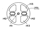
加工ステ−ション14は、図4および図5に示す中央に凹部141を、その凹部の両端に対称に設けた1組の凹部142,142ならびに2組の凹部143,143を有し、かつ底部144を有するワ−ク治具14a、錘14b、一対の連結ボルト14c,14c用孔を有する錘受板14d、前記一対の連結ボルト14c,14cを上下方向にスライド可能に保持するボ−ルブッシュ14e,14e、該ボ−ルブッシュの下部に設けられた前記、一対の連結ボルト14c,14c用の孔を有する連結板14f、該連結板14fの中央部に設けられた窪みより垂下された高さ調整ボルト14g、前記ワ−ク治具14aの中央凹部141に収容されたボ−ル14h、支軸13cへのガイド止めピン14i、該ガイド止めピン14iより起立させた位置合ヘッド14jよりなる。前記連結板14fの孔を貫通した連結ボルト14c,14cの下部先端はワ−ク治具14aの上面の凹部142,142内に挿入される。
錘14bの荷重は、錘受板14dにより一対の連結ボルト14c,14cに分散され、ワ−ク治具14aに負荷される。連結ボルト14c,14cはボ−ルブッシュ14e,14eをスライド可能に取り付けられており、このボ−ルブッシュの下部に設けられた連結板14fに前記一対の連結ボルト14c,14cはネジ止めされる。該連結板14fの中央部に設けられた窪みより垂下された高さ調整ボルト14gがワ−ク治具14aの上面の凹部141に置かれたボ−ル14hに当接する高さに連結ボルト14c,14cを連結板14fにネジ止めすることにより加工ステ−ションの高さ位置決めが行なわれる。
【0015】
また、ワ−ク治具14aの底部144にはワ−クwが接着される。ワ−クがMRヘッドの棒(幅1.2mm、高さ2mm、長さ50〜70mm)のように長尺状の小さいものであるときは複数のワ−クがク治具14aの底部に接着される。接着にはワックス、ポリエチレンなどのホットメルト接着剤、粘着テ−プ、紫外線硬化型粘着剤などが使用される。
【0016】
ワ−クへの荷重は、ワ−クの用途、ワ−クの加工度により異なるが10g/cm2〜10kg/cm2である。上記寸法の磁気ヘッド棒2本を治具に張り付けてのラップの際の錘の重さは、0.1〜2kgが好ましい。
【0017】
ワ−クのラップ加工時には、ポリシャ4上に研磨剤が供給される。研磨剤の種類は、ワ−クの用途により異なるが、ダイヤモンドスラリ−、アルミナスラリ−、酸化セリウムスラリ−、ベ−マイトスラリ−などが用いられる。AlTiCのような硬いワ−クの際はダイヤモンドスラリ−が最適である。
【0018】
ポリシャ4上への研磨剤の供給機構16,16’は、特開平11−151658号公報の図2(本願明細書では図7)に示すように加工ステ−ションの支軸を経てワ−ク治具に設けたスリットからポリシャ上に供給する供給機構16とともに、コンディショナ−10の環状内に供給する供給機構16’を併用する。
本明細書の図1と図3では、双方併用の例を示している。一方の研磨剤の供給機構16は、研磨剤供給ポンプ16aと研磨剤タンク16bを有し、タンク内の研磨剤はポンプにより加工ステ−ション14の支軸13cを経てワ−ク治具に設けたスリットからポリシャ4上に供給される。他方の研磨剤の供給機構16'はコンディショナ−10の環状内に供給するように研磨剤供給機構を軸承させている。
【0019】
ワ−クの用途により異なるが、テ−ブル3の回転数は1から30rpm、コンディショナ−の回転数は1から60rpmで、加工ステ−ションの矢印A方向の往復移動幅は1〜60mm、移動オシレ−ション速度は1〜25rpmである。
【0020】
【実施例】
実施例1〜3
図1に示す平面ラップ装置を用い、ワ−クとして長尺状のAlTiC製磁気ヘッド棒材をラップ加工した。錘をそれぞれ1kg、テ−ブルの回転数を3rpm、コンディショナ−の回転数を10rpm、加工ステ−ションの矢印A方向の往復移動幅を6mm、移動オシレ−ション速度を1.5rpmとし、ダイヤモンドスラリ−をワ−ク治具のスリットと、コンディショナ−の環状内に供給してラップ加工したとき(実施例1)は、得られたワ−クの表面平滑度は1.2μmであった。
また、ダイヤモンドスラリ−をワ−ク治具のスリットからのみ供給してラップ加工した際(実施例2)の、得られたワ−クの表面平滑度は1.8μmであり、ダイヤモンドスラリ−をコンディショナ−の環状内のみに供給してラップ加工した際(実施例3)の、得られたワ−クの表面平滑度は2.2μmであった。
【0021】
【発明の効果】
本発明の平面ラップ装置により加工されたワ−クは、表面平滑性に優れるものである。また、加工ステ−ションをポリシャ上に2基備えているので生産性が高い。
【図面の簡単な説明】
【図1】 本発明の平面ラップ装置の平面図である。
【図2】 平面ラップ装置の側面図である。
【図3】 平面ラップ装置の正面図である。
【図4】 加工ステ−ションの要部を示す正面図である。
【図5】 ワ−ク治具の平面図である。
【図6】 加工ステ−ション位置決め機構の要部を示す断面図である。
【図7】 公知のラップ装置である。
【図8】 公知のラップ装置の加工ステ−ションとテ−ブルとの関係を示す部分断面図である。
【符号の説明】
1 ラップ装置
w ワ−ク
2 基台
3 ポリシャ
4 テ−ブル
10 コンディショナ−
13 加工ステ−ション位置決め機構
14 加工ステ−ション
14a ワ−ク治具
14b 錘
16 研磨剤供給機構[0001]
BACKGROUND OF THE INVENTION
The present invention relates to a flat lapping apparatus used for lapping one side of a work such as a magnetic head substrate, a semiconductor silicon wafer, an LED glass substrate, or a ceramic substrate. The flat lapping apparatus of the present invention can provide a work having a surface smoothness (width of variation in thickness) of 1 to 3 μm.
[0002]
[Prior art]
In the conventional flat lapping apparatus, the surface shape of the polisher changes with the progress of the workpiece polishing (lapping), and the workpiece is placed at a specific position of the polisher in order to obtain a workpiece having a desired surface shape. There is a need for a flat lapping apparatus that suppresses a change in the surface shape of the polisher by constantly shaping the polisher with a conditioner during lapping, thereby improving the surface finish of the workpiece.
For example, Japanese Patent Application Laid-Open No. 11-151658 discloses a rotating table 101 having a
[0003]
In order to polish the workpiece using the lapping apparatus, the
As the table 101 rotates, the
[0004]
On the other hand, a disc-
[0005]
[Problems to be solved by the invention]
Since the planar lapping apparatus is constantly modifying the shape of the polisher with the conditioner at the same time as the lapping of the workpiece, the smoothness of the worked workpiece is processed with a conventional lapping apparatus of 5 to 8 μm. Although it is better than the above, it is not sufficient for applications requiring smoothness of 1 to 3 μm, such as GMR heads and MR heads using AlTiC substrates.
An object of the present invention is to provide a flat lapping apparatus that gives a lapped workpiece having a smoothness of 1 to 3 μm.
[0006]
[Means for Solving the Problems]
The present invention
A) rotatable tape in a horizontal direction having a metal cast polisher (4) - table (3),
B) An annular conditioner ( 10 ) for conditioning a polisher surface provided on the polisher (4) of the table,
C) A pair of claws (11a, 11a) surrounding about 2/3 of the outer periphery of the conditioner (10), a slave drive roller (11b, 11b) provided at the tip of the claws, and these claws A positioning mechanism ( 11 ) comprising a fixed frame (11 c) ,
D) The conditioner comprising a motor (12b) for driving a rotary roller (12a) provided in the fixed frame (11c) and the slave drive rollers (11b, 11b) . Rotation drive mechanism ( 12 ),
E) A machining step for a pair of workpieces provided at symmetrical positions with respect to the arrangement of the conditioner (10) and the positioning mechanism (11) of the conditioner and the rotary drive mechanism (12) of the conditioner. -Positioning mechanism ( 13 , 13 ),
F) A concave portion (141) in the center, a pair of concave portions (142, 142) and two sets of concave portions (143, 143) provided symmetrically at both ends of the concave portion, and a bottom portion (144). -A jig (14a), a weight (14b), a weight receiving plate (14d) having holes for a pair of connecting bolts (14c, 14c), and the pair of connecting bolts (14c, 14c) are slidable in the vertical direction. A holding ball bush (14e, 14e), a connecting plate (14f) having a hole for the pair of connecting bolts (14c, 14c) provided in the lower portion of the ball bush, provided in the center of the connecting plate; A height adjusting bolt (14g) suspended from the formed depression, a ball (14h) housed in the central recess (141) of the work jig (14a), and a guide stop to the support shaft (13c) Pin (14i), guide stop N'yori standing is allowed position if the head Wa attached to the jig consisting of (14j) (14a) - applying a load to the click (w), and Wa on polisher surface - a pair of working stearyl holding a click -( 14 , 14 ),
G) the word - click processing stearyl - Deployment driving mechanism for reciprocating the positioning mechanism (13) on the polisher (4) (15), and,
H) A mechanism (16) for supplying an abrasive onto the in-ring polisher (4) of the annular conditioner (10) and a support shaft (13a) of the work station positioning mechanism (13) of the workpiece. A mechanism (16 ′) for supplying the abrasive onto the polisher (4) from the slit provided in the work jig (14a)
A flat lapping apparatus (1) is provided.
[0007]
Conditioners - (10) Te of polisher (4) the rotation of - instead of being dependent on the rotation of the table (3), directly conditioner - by forcibly rotated by the rotary drive mechanism (12) Polisher repair is improved, thus reducing variations in surface smoothness of the workpiece. In addition, the work ( w) in contact with the surface of the polisher (4) is forcibly loaded with the weight (14b) , and a high polishing pressure is applied to the work. Since the surface is swung, the surface smoothness of the workpiece obtained by polishing is as excellent as 1 to 3 μm.
[0008]
Flat lapping machine of the present invention also includes conditioner - (10) is annular and one of the supply mechanism for supplying a polishing agent (16 ') of the abrasive conditioner - it is installed so as to supply into the ring and than that, Te - conditioner even centrifugal force depends on the abrasive by the rotation of the table (a) - abrasive ring becomes a wall is prevented from jumping out to the outside of a polisher, effectively abrasive Available.
[0009]
DETAILED DESCRIPTION OF THE INVENTION
Hereinafter, the present invention will be described in more detail with reference to the drawings.
1 is a plan view of a flat lapping apparatus of the present invention, FIG. 2 is a side view of the flat lapping apparatus, FIG. 3 is a front view of the flat lapping apparatus, and FIG. 4 is a main portion of a processing station for holding a workpiece. FIG. 5 is a plan view of a jig for holding a work, and FIG. 6 is a cross-sectional view showing a main part of the machining station positioning mechanism.
[0010]
1, 2 and 3, 1 is a flat lapping device, w is a work, 2 is a base, 3 is a rotating table, 4 is a polisher having a cavity in the center, 5 is a spindle shaft, and 6 is a spindle shaft. A table rotation drive motor, 7 is a pulley, 8 is a belt, and 9 is a pulley.
A
[0011]
10 is a conditioner, 11 is a positioning mechanism for the conditioner, and 12 is a rotational drive mechanism for the conditioner. The
The conditioner positioning mechanism 11 includes a pair of claws 11a and 11a that surround about 2/3 of the outer periphery of the
[0012]
A pair of workpiece machining station positioning mechanisms 13 and 13 and
The machining station positioning mechanism 13 includes a
[0013]
The machining
A drive mechanism 15 for reciprocating the
The rotational drive of the
[0014]
The
The load of the
[0015]
Also, the workpiece w is bonded to the
[0016]
The load on the workpiece is 10 g / cm 2 to 10 kg / cm 2, although it varies depending on the usage of the workpiece and the work degree of the workpiece. The weight of the weight at the time of lapping with two magnetic head rods of the above dimensions attached to a jig is preferably 0.1 to 2 kg.
[0017]
An abrasive is supplied onto the
[0018]
As shown in FIG. 2 (FIG. 7 in this specification) of Japanese Patent Application Laid-Open No. 11-151658, the
FIG. 1 and FIG. 3 of this specification show examples of using both. One
[0019]
Although depending on the use of the work, the rotational speed of the table 3 is 1 to 30 rpm, the rotational speed of the conditioner is 1 to 60 rpm, and the reciprocating movement width in the direction of arrow A of the machining station is 1 to 60 mm. The movement oscillation speed is 1-25 rpm.
[0020]
【Example】
Examples 1-3
Using a flat lapping apparatus shown in FIG. 1, a long AlTiC magnetic head bar material was lapped as a workpiece. Each of the weights is 1 kg, the rotation speed of the table is 3 rpm, the rotation speed of the conditioner is 10 rpm, the reciprocation width of the machining station in the direction of arrow A is 6 mm, the movement oscillation speed is 1.5 rpm, diamond When the slurry was supplied into the slit of the work jig and the ring of the conditioner and lapped (Example 1), the surface smoothness of the obtained work was 1.2 μm. .
When the diamond slurry was supplied only from the slit of the workpiece jig and lapped (Example 2), the surface smoothness of the obtained workpiece was 1.8 μm, and the diamond slurry was When the lapping was carried out by supplying only into the conditioner ring (Example 3), the surface smoothness of the obtained workpiece was 2.2 μm.
[0021]
【The invention's effect】
The work machined by the flat lapping apparatus of the present invention is excellent in surface smoothness. Further, since two processing stations are provided on the polisher, the productivity is high.
[Brief description of the drawings]
FIG. 1 is a plan view of a flat lapping apparatus according to the present invention.
FIG. 2 is a side view of the flat lapping apparatus.
FIG. 3 is a front view of the flat lapping apparatus.
FIG. 4 is a front view showing a main part of a processing station.
FIG. 5 is a plan view of a work jig.
FIG. 6 is a cross-sectional view showing a main part of a machining station positioning mechanism.
FIG. 7 is a known lapping device.
FIG. 8 is a partial cross-sectional view showing a relationship between a processing station and a table of a known lapping apparatus.
[Explanation of symbols]
1 Wrap
13 Work
Claims (1)
Priority Applications (1)
| Application Number | Priority Date | Filing Date | Title |
|---|---|---|---|
| JP19116399A JP4210003B2 (en) | 1999-07-06 | 1999-07-06 | Flat lapping machine |
Applications Claiming Priority (1)
| Application Number | Priority Date | Filing Date | Title |
|---|---|---|---|
| JP19116399A JP4210003B2 (en) | 1999-07-06 | 1999-07-06 | Flat lapping machine |
Publications (2)
| Publication Number | Publication Date |
|---|---|
| JP2001018160A JP2001018160A (en) | 2001-01-23 |
| JP4210003B2 true JP4210003B2 (en) | 2009-01-14 |
Family
ID=16269959
Family Applications (1)
| Application Number | Title | Priority Date | Filing Date |
|---|---|---|---|
| JP19116399A Expired - Fee Related JP4210003B2 (en) | 1999-07-06 | 1999-07-06 | Flat lapping machine |
Country Status (1)
| Country | Link |
|---|---|
| JP (1) | JP4210003B2 (en) |
Families Citing this family (3)
| Publication number | Priority date | Publication date | Assignee | Title |
|---|---|---|---|---|
| JP5877520B2 (en) * | 2011-08-10 | 2016-03-08 | 株式会社岡本工作機械製作所 | Planarization processing apparatus and planarization processing method for sapphire substrate |
| CN109397088B (en) * | 2018-12-18 | 2024-01-09 | 东莞市金太阳精密技术有限责任公司 | Polishing machine capable of quickly replacing grinding head or grinding head clamp |
| CN111962003B (en) * | 2020-08-07 | 2022-06-07 | 合力(天津)能源科技股份有限公司 | Tungsten carbide spraying equipment with grinding and surface defect repairing functions |
-
1999
- 1999-07-06 JP JP19116399A patent/JP4210003B2/en not_active Expired - Fee Related
Also Published As
| Publication number | Publication date |
|---|---|
| JP2001018160A (en) | 2001-01-23 |
Similar Documents
| Publication | Publication Date | Title |
|---|---|---|
| JP3120116B2 (en) | Polishing apparatus and method | |
| KR100435251B1 (en) | Apparatus for finishing glass product | |
| US6478660B2 (en) | Apparatus of and method for polishing the outer circumferential portions of a circular plate-shaped work | |
| EP1184134A3 (en) | Machining center with dressing tool | |
| JP4210003B2 (en) | Flat lapping machine | |
| JP3990205B2 (en) | Polishing equipment | |
| CN109414800A (en) | The dressing method of the dressing mechanism of blade, the cutting apparatus for having the mechanism and the blade using the mechanism | |
| CN114505780A (en) | High-precision leveling type plane polishing machine | |
| JPS61146471A (en) | Dressing device | |
| JPH1029142A (en) | Mirror chamfering and machining method for disk semiconductor wafer chamfered section | |
| CN112959185A (en) | Special abrasive belt polishing equipment for spherical part with through hole | |
| JP2001054857A (en) | Manufacture of long workpiece having curvature surface and plane lapping device used for it | |
| JP2004122251A (en) | Grinding wheel dressing method and device for grinder | |
| JP4205263B2 (en) | Automatic lapping apparatus and substrate polishing method using the same | |
| JP4245987B2 (en) | Grinding equipment | |
| KR101273938B1 (en) | Polishing method using pad tool with a lower position | |
| KR200378324Y1 (en) | A driver roller for grinder | |
| KR102381559B1 (en) | Grinding system | |
| CN218984300U (en) | Coating film passivation treatment tool based on milling cutter machining | |
| CN211073031U (en) | Groove wall grinding device of grooved workpiece for machining | |
| JPS63150108A (en) | Grooving device | |
| JPH04146072A (en) | Mirror-surface polishing apparatus and method for stainless coil | |
| JP2018001355A (en) | Method for grinding rectangular work-piece | |
| JP2003117820A (en) | Truing device for grinding wheel | |
| JP2002066931A (en) | Grinding wheel and method and device for mirror finished surface grinding |
Legal Events
| Date | Code | Title | Description |
|---|---|---|---|
| A621 | Written request for application examination |
Free format text: JAPANESE INTERMEDIATE CODE: A621 Effective date: 20060621 |
|
| A977 | Report on retrieval |
Free format text: JAPANESE INTERMEDIATE CODE: A971007 Effective date: 20080423 |
|
| A131 | Notification of reasons for refusal |
Free format text: JAPANESE INTERMEDIATE CODE: A131 Effective date: 20080527 |
|
| A521 | Written amendment |
Free format text: JAPANESE INTERMEDIATE CODE: A523 Effective date: 20080602 |
|
| TRDD | Decision of grant or rejection written | ||
| A01 | Written decision to grant a patent or to grant a registration (utility model) |
Free format text: JAPANESE INTERMEDIATE CODE: A01 Effective date: 20081021 |
|
| A01 | Written decision to grant a patent or to grant a registration (utility model) |
Free format text: JAPANESE INTERMEDIATE CODE: A01 |
|
| A61 | First payment of annual fees (during grant procedure) |
Free format text: JAPANESE INTERMEDIATE CODE: A61 Effective date: 20081024 |
|
| R150 | Certificate of patent or registration of utility model |
Free format text: JAPANESE INTERMEDIATE CODE: R150 |
|
| FPAY | Renewal fee payment (event date is renewal date of database) |
Free format text: PAYMENT UNTIL: 20111031 Year of fee payment: 3 |
|
| FPAY | Renewal fee payment (event date is renewal date of database) |
Free format text: PAYMENT UNTIL: 20121031 Year of fee payment: 4 |
|
| FPAY | Renewal fee payment (event date is renewal date of database) |
Free format text: PAYMENT UNTIL: 20121031 Year of fee payment: 4 |
|
| FPAY | Renewal fee payment (event date is renewal date of database) |
Free format text: PAYMENT UNTIL: 20131031 Year of fee payment: 5 |
|
| R250 | Receipt of annual fees |
Free format text: JAPANESE INTERMEDIATE CODE: R250 |
|
| R250 | Receipt of annual fees |
Free format text: JAPANESE INTERMEDIATE CODE: R250 |
|
| R250 | Receipt of annual fees |
Free format text: JAPANESE INTERMEDIATE CODE: R250 |
|
| LAPS | Cancellation because of no payment of annual fees |