JP4187411B2 - Device for use in closing a septal defect - Google Patents
Device for use in closing a septal defect Download PDFInfo
- Publication number
- JP4187411B2 JP4187411B2 JP2000529190A JP2000529190A JP4187411B2 JP 4187411 B2 JP4187411 B2 JP 4187411B2 JP 2000529190 A JP2000529190 A JP 2000529190A JP 2000529190 A JP2000529190 A JP 2000529190A JP 4187411 B2 JP4187411 B2 JP 4187411B2
- Authority
- JP
- Japan
- Prior art keywords
- fingers
- connector
- finger
- axis
- inner portion
- Prior art date
- Legal status (The legal status is an assumption and is not a legal conclusion. Google has not performed a legal analysis and makes no representation as to the accuracy of the status listed.)
- Expired - Lifetime
Links
Images


Classifications
-
- A—HUMAN NECESSITIES
- A61—MEDICAL OR VETERINARY SCIENCE; HYGIENE
- A61B—DIAGNOSIS; SURGERY; IDENTIFICATION
- A61B17/00—Surgical instruments, devices or methods, e.g. tourniquets
- A61B17/34—Trocars; Puncturing needles
- A61B17/3468—Trocars; Puncturing needles for implanting or removing devices, e.g. prostheses, implants, seeds, wires
-
- A—HUMAN NECESSITIES
- A61—MEDICAL OR VETERINARY SCIENCE; HYGIENE
- A61B—DIAGNOSIS; SURGERY; IDENTIFICATION
- A61B17/00—Surgical instruments, devices or methods, e.g. tourniquets
- A61B17/0057—Implements for plugging an opening in the wall of a hollow or tubular organ, e.g. for sealing a vessel puncture or closing a cardiac septal defect
-
- A—HUMAN NECESSITIES
- A61—MEDICAL OR VETERINARY SCIENCE; HYGIENE
- A61B—DIAGNOSIS; SURGERY; IDENTIFICATION
- A61B17/00—Surgical instruments, devices or methods, e.g. tourniquets
- A61B17/11—Surgical instruments, devices or methods, e.g. tourniquets for performing anastomosis; Buttons for anastomosis
-
- A—HUMAN NECESSITIES
- A61—MEDICAL OR VETERINARY SCIENCE; HYGIENE
- A61F—FILTERS IMPLANTABLE INTO BLOOD VESSELS; PROSTHESES; DEVICES PROVIDING PATENCY TO, OR PREVENTING COLLAPSING OF, TUBULAR STRUCTURES OF THE BODY, e.g. STENTS; ORTHOPAEDIC, NURSING OR CONTRACEPTIVE DEVICES; FOMENTATION; TREATMENT OR PROTECTION OF EYES OR EARS; BANDAGES, DRESSINGS OR ABSORBENT PADS; FIRST-AID KITS
- A61F2/00—Filters implantable into blood vessels; Prostheses, i.e. artificial substitutes or replacements for parts of the body; Appliances for connecting them with the body; Devices providing patency to, or preventing collapsing of, tubular structures of the body, e.g. stents
- A61F2/02—Prostheses implantable into the body
- A61F2/04—Hollow or tubular parts of organs, e.g. bladders, tracheae, bronchi or bile ducts
- A61F2/06—Blood vessels
- A61F2/064—Blood vessels with special features to facilitate anastomotic coupling
-
- A—HUMAN NECESSITIES
- A61—MEDICAL OR VETERINARY SCIENCE; HYGIENE
- A61B—DIAGNOSIS; SURGERY; IDENTIFICATION
- A61B17/00—Surgical instruments, devices or methods, e.g. tourniquets
- A61B17/064—Surgical staples, i.e. penetrating the tissue
-
- A—HUMAN NECESSITIES
- A61—MEDICAL OR VETERINARY SCIENCE; HYGIENE
- A61B—DIAGNOSIS; SURGERY; IDENTIFICATION
- A61B17/00—Surgical instruments, devices or methods, e.g. tourniquets
- A61B17/064—Surgical staples, i.e. penetrating the tissue
- A61B17/0643—Surgical staples, i.e. penetrating the tissue with separate closing member, e.g. for interlocking with staple
-
- A—HUMAN NECESSITIES
- A61—MEDICAL OR VETERINARY SCIENCE; HYGIENE
- A61B—DIAGNOSIS; SURGERY; IDENTIFICATION
- A61B17/00—Surgical instruments, devices or methods, e.g. tourniquets
- A61B17/08—Wound clamps or clips, i.e. not or only partly penetrating the tissue ; Devices for bringing together the edges of a wound
-
- A—HUMAN NECESSITIES
- A61—MEDICAL OR VETERINARY SCIENCE; HYGIENE
- A61B—DIAGNOSIS; SURGERY; IDENTIFICATION
- A61B17/00—Surgical instruments, devices or methods, e.g. tourniquets
- A61B17/34—Trocars; Puncturing needles
- A61B17/3415—Trocars; Puncturing needles for introducing tubes or catheters, e.g. gastrostomy tubes, drain catheters
-
- A—HUMAN NECESSITIES
- A61—MEDICAL OR VETERINARY SCIENCE; HYGIENE
- A61B—DIAGNOSIS; SURGERY; IDENTIFICATION
- A61B17/00—Surgical instruments, devices or methods, e.g. tourniquets
- A61B17/0057—Implements for plugging an opening in the wall of a hollow or tubular organ, e.g. for sealing a vessel puncture or closing a cardiac septal defect
- A61B2017/00575—Implements for plugging an opening in the wall of a hollow or tubular organ, e.g. for sealing a vessel puncture or closing a cardiac septal defect for closure at remote site, e.g. closing atrial septum defects
-
- A—HUMAN NECESSITIES
- A61—MEDICAL OR VETERINARY SCIENCE; HYGIENE
- A61B—DIAGNOSIS; SURGERY; IDENTIFICATION
- A61B17/00—Surgical instruments, devices or methods, e.g. tourniquets
- A61B17/0057—Implements for plugging an opening in the wall of a hollow or tubular organ, e.g. for sealing a vessel puncture or closing a cardiac septal defect
- A61B2017/00646—Type of implements
- A61B2017/00659—Type of implements located only on one side of the opening
-
- A—HUMAN NECESSITIES
- A61—MEDICAL OR VETERINARY SCIENCE; HYGIENE
- A61B—DIAGNOSIS; SURGERY; IDENTIFICATION
- A61B17/00—Surgical instruments, devices or methods, e.g. tourniquets
- A61B17/064—Surgical staples, i.e. penetrating the tissue
- A61B2017/0641—Surgical staples, i.e. penetrating the tissue having at least three legs as part of one single body
Landscapes
- Health & Medical Sciences (AREA)
- Life Sciences & Earth Sciences (AREA)
- Surgery (AREA)
- General Health & Medical Sciences (AREA)
- Animal Behavior & Ethology (AREA)
- Veterinary Medicine (AREA)
- Engineering & Computer Science (AREA)
- Biomedical Technology (AREA)
- Heart & Thoracic Surgery (AREA)
- Public Health (AREA)
- Molecular Biology (AREA)
- Nuclear Medicine, Radiotherapy & Molecular Imaging (AREA)
- Medical Informatics (AREA)
- Cardiology (AREA)
- Gastroenterology & Hepatology (AREA)
- Pathology (AREA)
- Transplantation (AREA)
- Vascular Medicine (AREA)
- Pulmonology (AREA)
- Oral & Maxillofacial Surgery (AREA)
- Prostheses (AREA)
- Infusion, Injection, And Reservoir Apparatuses (AREA)
- Surgical Instruments (AREA)
- Materials For Medical Uses (AREA)
- Pharmaceuticals Containing Other Organic And Inorganic Compounds (AREA)
- Electrotherapy Devices (AREA)
Abstract
Description
【0001】
(発明の背景)
本発明は、管状医療用移植片と患者の管状の身体導管との間で接続を作るのに使用できる構造体に関する。本発明の構造体は、あるいは、(例えば、心房または心室の中隔欠損を閉じるための)医療用プラグとして使用するために構成され得る。本発明はまた、上記構造体を製造し使用する方法に関する。
【0002】
管状移植片は、しばしば、医療処置で必要とされる。例えば、冠状バイパス処置は、大動脈の側壁で形成された開口部と、冠状動脈の側壁(これは、その動脈にある閉塞部または妨害物から下流にある)で形成された開口部との間にて、管状移植片を設置することを包含し得る。この移植片の各末端は、大動脈または冠状動脈のいずれかの側壁に接続されなければならない。このような接続部の各々は、血液が漏れないように、この移植片導管に付随した末端の回りで、環状に伸長して、液密でなければならない。このような接続部を作製する1つの通例の方法は、縫合による。しかしながら、縫合によりこのような接続部を作ることは、非常に困難であり、時間がかかり、また、その結果の出来映えは、医師の技術に依存する。また、浸襲性の少ない処置に対する関心が高まっているが、この処置では、移植片接続部を作製しなければならない部位への医師のアクセスに対して制約が課せられる傾向にあり、それにより、このような接続を作製するのに縫合を使用することが困難または不可能でさえある(例えば、1996年11月7日に出願されたGoldsteenらの米国特許出願第08/745,618号;1997年4月23日に出願されたSullivanらの米国特許出願第08/844,992号;および1997年6月5日に出願されたSullivanらの米国特許出願第08/869,808号;これらの全ての内容は、本明細書中で完全に参考として援用されている)。縫合の必要性を少なくするかまたはなくすために、種々の型の機械的コネクタが開発されているが、使用の容易性および速度、製造の容易性、得られる接続の強度および耐久性などに関して、このような機械的コネクタに対して、絶えず、改良が求められている。
【0003】
プラグもまた、種々の医療処置で必要とされている。例えば、新生児の心臓にある心房または心室の中隔欠損を塞ぐことが必要であり得る。再度、最小の浸襲性の処置を用いて、容易かつ迅速に設置できるプラグに対して、絶えず、改良が求められる。
【0004】
前述のことを考慮して、本発明の目的は、改良し簡単にした移植片コネクタを提供することにある。
【0005】
本発明の別の目的は、改良し簡単にした医療用プラグを提供することにある。
【0006】
本発明のさらに別の目的は、医療用移植片コネクタまたはプラグのいずれかとして使用できる構造体を製造するための改良し簡単にした方法を提供することにある。
【0007】
本発明のさらに別の目的は、医療用移植片コネクタまたはプラグを設置するための改良し簡単にした方法を提供することにある。
【0008】
(発明の要旨)
本発明のこれらの目的および他の目的は、好ましくは、弾性の高い材料(例えば、ニッケルおよびチタン合金(ニチノール)金属)のチューブから出発して形成されたコネクタまたはプラグ構造体を提供することにより、本発明の原理に従って達成される。そのチューブの各末端部は、このチューブの回りで円周方向に間隔を空けて多数の位置で実質的に軸方向に切断されて、複数のフィンガーが作製されるが、これらは、このチューブの残りの内側部の各末端から、実質的に軸方向に伸長している。この内側部の各末端にあるフィンガーは、次いで、この内側部から実質的に放射状に伸長するように、反らされ、そしてこれらのフィンガーは、その反らした状態で、(例えば、熱処理により)セットされる。この構造体を移植片コネクタとして使用するためには、この内側部は、移植片導管の末端部に実質的に同軸状に装着される。この構造体をプラグとして使用するためには、このチューブの内側部は、適切なプラギング(plugging)材料または構造体で満たされる。
【0009】
この移植片コネクタまたはプラグを患者内に設置するためには、これらのフィンガーは、この内側部の各軸末端部にて、その初期状態(この状態では、これらのフィンガーは、この内側部の末端から実質的に軸方向に伸長する)へと、弾力的に変形され得る。この構造体は、次いで、送達チューブ(これは、これらのフィンガーを、その実質的に軸方向で伸長する状態で、維持し得る)に挿入され得る。この送達チューブは、次いで、この移植片導管の末端を装着すべき患者の管状人体導管の側壁にある開口部を通って、または塞ぐべき患者の組織構造にある開口部を通って、挿入され得る。この送達導管は、次いで、このコネクタまたはプラグ構造体の回りから、取り外され得る。これにより、これらのフィンガーは、この内側部の各末端から解除され、この接続を作製すべき組織構造、またはプラグを適用すべき組織構造の各個の反対側で、跳ね返る。
【0010】
ある場合には、フィンガーは、出発チューブの一端でだけ形成され得る。次いで、互いとおよび移植片導管と同心円状のこのような2個のチューブを用いて、コネクタが提供される。このようなアセンブリでは、これらの2個のチューブ上のフィンガーは、一般に、このアセンブリの反対の軸末端から伸長している。このような2個のチューブは、プラグを作製するために、同じように使用され得るが、この場合では、この移植片導管は、省略され、そしてこの構造体の内部は、プラギング材料または構造体で満たされる。
【0011】
フィンガーをコネクタまたはプラグの長手軸に実質的に平行に解除可能に保持するために、送達チューブの使用に代えてまたはそれに加えて、別の構造体が、これらのフィンガーの回りに取り外し可能に配置され得る。このような別の構造体の例には、材料のカラーまたはストランド(例えば、ワイヤまたは縫合材料)が挙げられる。
【0012】
本発明のさらなる特徴、その性質および種々の利点は、添付の図面および好ましい実施態様の以下の詳細な説明から、さらに明らかとなる。
【0013】
(好ましい実施態様の詳細な説明)
本発明のコネクタまたはプラグ構造体の例証的な出発部品は、図1および2で示すように、中空チューブ10である。チューブ10は、完成したコネクタまたはプラグ構造体の意図した用途に適切な任意の長さ、直径および壁厚を有し得る。心臓バイパス移植片コネクタとして使用するためには、例えば、チューブ10は、約4.0ミリメートルの直径、約0.003インチの壁厚、および約7.0ミリメートルの長さを有し得る。しかしながら、これらの特定の寸法は、代表的なものにすぎず、もし望ましいなら、任意の他の寸法が代わりに使用できることが分かる。チューブ10の材料は、好ましくは、非常に弾性である。特に好ましい材料には、ニッケルチタン合金(ニチノール)金属(これは、それ自体、通常であり得る)があるが、ステンレス鋼または熱可塑性物質のような他の材料は、もし望ましいなら、その代わりに使用できる。
【0014】
本発明に従ってチューブ10を処理する第一工程は、図3で示すように、各軸末端部の回りに同心円状に間隔を空けて多くの位置12にて、それを実質的に軸方向に切断することである。切片12は、出発チューブ10を、未切断医療用チューブ部分16の各末端から実質的に軸方向に伸長している複数のフィンガー14へと縮小する。切片12は、任意の適切な技術(例えば、放電加工(「EDM」)、レーザー切断、またはエッチング)により、作製され得る。内側部16の長さは、この構造体の意図した用途に基づいて、選択され得る。例えば、内側部16の長さは、この内側部が伸長する患者の身体組織の厚さに対応するように、選択され得る。内側部16の例証的な長さは、約0.2ミリメートル〜約4.0ミリメートルの範囲である。フィンガー14の長さはまた、この構造体の意図した用途に基づいて、選択され得る。フィンガー14の例証的な長さは、約1.0ミリメートル〜約10.0ミリメートルの範囲である。
【0015】
次の工程は、フィンガー14を、仕上げし設置したコネクタまたはプラグ構造体にそれらを配置するのが望ましい大体の位置へと反らせることである。例えば、図4および5は、各フィンガーを装着する内側部16の末端から実質的に放射状外側に反れるフィンガー14を示す。図4および5は、各フィンガー14間の角度Aおよび内側部16の隣接して軸方向に伸長している表面をおよそ90°として示しているものの、広範囲の角度A(例えば、約45°〜約120°の範囲)が使用できることが分かる。実際、種々のフィンガー14の反り角度は、もし望ましいなら、異なり得る。さらに、フィンガー14は、もし望ましいなら、真っ直ぐよりもむしろ曲げられ(例えば、内側部16から放射状外側に伸長している平面から見て、凹状に曲げられ)、限定的な角度Aによる外向きの反りの代わりに、これらのフィンガーの事実上外向きの湾曲が使用できる。例えば、一端または両端でのフィンガー14の自由末端は、他端でのこれらのフィンガーの自由末端に向かって曲がることができ、またはそれと重なり合うことさえできる。図6およびいくらかそれに引き続いた図は、フィンガー14のこのような湾曲の例を示している。図17は、重なり合っているフィンガー14の一例を示している。しかしながら、一般に、フィンガー14は、内側部16から放射状の外向き伸長部の部品を少なくとも1つ有するように、反らされる。便宜上および簡単にするために、本明細書中では、従って、時には、フィンガー14は、内側部16から放射状外側に伸長すると言われるが、この語は、(1)このような放射状の外向き伸長部の部品だけを有するフィンガー、および(2)実質的に直線状または曲線状のいずれかであるフィンガーを包含することが分かる。
【0016】
フィンガー14を引き続いて展開中に解除したとき、それらが、その製造のこの工程で反らした位置まで戻るために、このコネクタまたはプラグをこれらの試みの中で、設置する組織に弾性的に凭れるように、これらのフィンガー14をその所望の最終位置を超えて反らすのが望まれ得ることも分かる。例えば、もし、図4が、患者内で使用するフィンガー14の所望の最終位置(すなわち角度A=90°)を示すなら、この製造プロセスのこの工程では、フィンガー14が内側部16を取り囲む組織と係合する保証を高めるために、フィンガー14を図4で示す以上に反らせる(例えば、角度A=60°)ことが望まれ得る。それにもかかわらず、便宜上および簡単にするために、本明細書中では、時には、この製造工程にて、フィンガー14は、大体、その意図した(少なくとも)最終位置に反らされると言われ、この語は、フィンガーを、実際に意図した最終位置を超えて反らせる工程を包含することが分かる。
【0017】
フィンガー14を、(例えば、図4および5で示すように)、大体、その最終的に意図した位置に反らした場合、フィンガー14は、その位置でセットされる。例えば、フィンガー14をその反らした位置でセットするには、この構造体に熱処理が加えられ得る。
【0018】
図6〜8は、移植片導管30の末端に対してコネクタ20を提供するために、図4および5で示した型の構造体を使用することを示している。(移植片コネクタよりもむしろプラグとしての図4および5で示した型の構造体の可能な代替的使用は、このコネクタ実施態様の説明が実質的に完結した後、論述する)。移植片導管30は、天然導管(例えば、患者の管状身体組織の再配置部分)、人工導管(例えば、上記出願第08/745,618号で示した型のもの)、または天然導管および人工導管の複合体であり得る。
【0019】
図6で示した例証的な実施態様では、移植片導管30の軸方向末端部は、内側部16に実質的に同軸状に挿入され、そこに装着されている。部品20および30の材料に依存して、それらは、任意の適切な手段(例えば、縫合、接着剤、溶接など)により、共に固定され得る。
【0020】
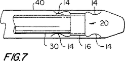
移植片30およびコネクタ20を使用する際の次の工程は、図7で示すように、そのアセンブリを送達チューブ40に挿入することにある。チューブ40は、好ましくは、内側部16または移植片導管30よりも、直径が僅かに大きい。構造体20をチューブ40に嵌め込むためには、フィンガー14は、図7で示すように、内側部16の末端からの軸方向伸長部として、それらの初期位置に方へと弾力的に反らされる。言い換えれば、フィンガー14は、内側部16の中心長手軸と平行位置に向かって、内向きに弾性的に反らされている。もし、コネクタ20がニチノールから製造されるなら、この工程では、送達チューブ40での部品20および30の組み立てを容易にするために、このコネクタの一時的な過冷却が使用され得る(移植片導管30が過冷却コネクタ20に近づくことに耐えられると仮定して)。フィンガー14を真っ直ぐにできるように、また、部品20および30をチューブ40に挿入するために形状を保持するように、過冷却ニチノールにより、それを可塑性に変える。コネクタ20を再度暖めたとき、それは、放射状に外向きに反らした後、これらのフィンガーをセットする工程中に示した形状を「記憶する」。
【0021】
図7で示したアセンブリを使用する際に次の工程は、移植片導管30をコネクタ20により接続すべき患者の管状身体導管(図8では50)の側壁にある開口部を通って、送達チューブ40を挿入することである。例えば、送達チューブ40のテーパーを付けた遠位末端部(図7では、右側で示した)は、チューブ40が、管状身体導管側壁52にある開口部に入るのを助けるのに使用され得る。要素20、30および40は、好ましくは、内側部16が側壁52のほぼ中央に置かれるように、側壁52に対して位置づけられる。これは、内側部16の他の末端にあるフィンガー14を導管50の外側にしつつ、内側部16の軸末端にあるフィンガー14を導管50の内側に配置する。
【0022】
次の工程は、図8で図示されており、そして部品20および30を側壁52に対して固定して保持しつつ、側壁52にある開口部から送達チューブ40を引き出すことを包含する。送達チューブ40をそのように引き出すにつれて、導管50の内側上にあるフィンガー14は、徐々に解除されて、側壁52を通る開口部の回りで、その壁の内側に弾性的に跳ね返る。その後、送達チューブ40が引き続いて後退するにつれて、導管50の外側上にあるフィンガー14もまた解除されて、側壁52を通る開口部の回りで、その壁の外側に弾性的に跳ね返る。それゆえ、コネクタ20の最終状態は、図8で示したとおりである(だがもちろん、送達チューブ40は、最終的に、患者から完全に引き出される)。導管50の内側上にあるフィンガー14は、このコネクタおよび移植片導管が側壁52にある開口部から引き出されるのを防止する。導管50の外側にあるフィンガー14は、このコネクタおよび移植片導管が導管50へと好ましくない程に遠くに突出するのを防止する。
【0023】
図7および8は、導管50の外側からこの導管の側壁52にある開口部へとコネクタ20を挿入することを示しているものの、コネクタ20は、その代わりに、導管50の管腔に内側から挿入できる。その場合、コネクタ20は、典型的には、送達チューブ40の内側部に位置しており、移植片導管30は、チューブ40の内部に沿った遠位方向で、このコネクタから伸長している。チューブ40は、次いで、壁52にある開口部の位置に達するまで、管内的に、導管50に挿入される。チューブ40は、次いで、内側部16が壁52上の中央になるまで、壁52にある開口部を通過する。部品20および30は、次いで、チューブ40が導管50の管腔を経由して近位に引き戻されるにつれて、導管50に対して固定して保持され、それにより、フィンガー14が、側壁52にある開口部の回りで、その側壁の内面および外面に跳ね返って、それと係合することができるように、移植片導管30を導管50の外側に露出し、同様に、コネクタ20を露出する。別個の軸方向に伸長しているプッシャーまたはホルダー構造体は、チューブ40を近位に引き戻している間、上記のように、部品20および30を固定して保持するのを助けるために、チューブ40の内側にある必要があり得る。
【0024】
図9は、図4および5で示した型の構造体をプラグ60として使用するのに適合する代替的実施態様を示す。この代替物では、内側部16は、実質的に、シリコーンまたは熱可塑性物質のようなプラグ材料または構造体70で満たされるかまたは閉塞される。プラグ60は、次いで、図7で部品20と共にチューブ40を使用するのと実質的に同じ様式で、図10で示したように、送達チューブ40に挿入される。
【0025】
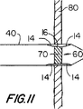
アセンブリ40/60を使用する際の次の工程は、図11で示すように、塞ぐべき組織構造体80にある開口部を通って、チューブ40を挿入することにある。先に記述したコネクタ実施態様のように、アセンブリ40/60は、好ましくは、内側部16の一方の軸末端から伸長しているフィンガー14が構造体80の一側面にあるように、また、内側部16の他の軸末端から伸長しているフィンガー14が構造体80の他の側面にあるように、組織構造体80に対して配置される。
【0026】
次の工程は、プラグ60を構造体80に対して実質的に固定して保持しつつ、組織構造体80にある開口部からチューブ40を引き出すことである。プラグ60をこのようにして固定するためには、ホルダーチューブ(図示せず)は、このホルダーチューブの遠位末端がプラグ構造体70に凭れるまで、チューブ40に挿入され得る。次いで、このホルダーチューブは、チューブ40を引き出している間、組織構造体80に対して、固定して保持できる。チューブ40を引き出しつつ、構造体80の右手側にあるフィンガー14は、図11および12で見えるように、徐々に解除されて、構造体80のその側面に対して、弾力的に跳ね返る。さらに、チューブ40を引き出すことにより、構造体80の左手側にあるフィンガーは、構造体80のその側面に対して、弾性的に跳ね返ることができる。完成したプラグの設置は、図12で示したとおりである。
【0027】
コネクタ20の場合のように、プラグ60は、組織構造体80のいずれかの側面からこの組織構造体にある開口部へと挿入されることができ、そしてチューブ40は、同様に、いずれかの方向で引き出すことができる。例えば、もし、組織構造体80が導管またはチャンバの壁であるなら、プラグ60は、その導管またはチャンバの内側または外側のいずれかから設置でき、そしてチューブ40は、その導管またはチャンバの内側または外側のいずれかを経由して、引き出すことができる。
【0028】
上記コネクタまたはプラグ構造体の製造は、要素14および16が全て1個の出発構造体(すなわち、チューブ10)にに由来しているという事実により、非常に容易にされる。要素14および16は、従って、全ての時点で不可欠であり、別の成分の比較的に小さいフィンガー14の組み立てを試みる必要はない。本発明のコネクタまたはプラグ構造体の使用は、非常に容易である。何故なら、患者の適切な組織に対して、このコネクタまたはプラグを正しく配置すること、次いでこのコネクタまたはプラグの回りから送達チューブ40を引き出すことだけが必要であるからである。フィンガー14は、このコネクタまたはプラグを完成し固定するのに必要な位置へと、自動的に跳ね返る。
【0029】
もし望ましいなら、内側部16は、本発明に従ってコネクタまたはプラグを製造する過程において、任意の適切な時点で、穿孔できる。例えば、図13は、内側部16にある多くの穿孔16bを示しており、それにより、この内側部は、効率よく、内側部を部材16aの開放メッシュに減少する。内側部16のこのような穿孔は、その可撓性(例えば、軸方向および放射状の方向での)を高め得、従って、患者の体内でのその長期間の適合性を高め得る。可撓性コネクタまたはプラグの放射状の方向追従性(すなわち、このような構造体が、円周において弾力的に高くまたは低くなる性能)は、長期間の身体系路の管腔開放度に関して、有益であると考えられている。内側部16の可撓性および放射状の方向追従性を高めることもまた、このコネクタまたはプラグの送達および/または設置を容易にし得る。例えば、内側部16の可撓性により、コネクタまたはプラグは、比較的に小さいサイズまで、弾力的に円周方向に圧縮できるようになり、このコネクタまたはプラグの設置部位への送達(例えば、患者の身体導管の管腔を通る送達)を容易にし得る。このコネクタたまたはプラグを、その円周方向に圧縮したサイズで、患者の身体の所望部位に送達した後、このコネクタまたはプラグは、その初期のより大きいサイズまで自動的に戻ることができるように、この送達装置から開放される。天然組織移植片用のコネクタの場合には、内側部16の穿孔により、この移植片の組織およびこの移植片が接続されている導管の組織は、この穿孔を通って、共に成長できるようになり得る。
【0030】
内側部16の穿孔により、また、コネクタまたはプラグの一部は、このコネクタまたはプラグを設置した後、長期間ベースで、その周囲組織に対して、弾力的で放射状に外向きの力を加えることが可能になり得る。これは、この周囲組織のより堅固な係合、このコネクタまたはプラグの回りでの液体の漏れ可能性の低下などのような目的のために、有用であり得る。例えば、もし、この周囲組織の弾性的な跳ね返りが、長時間にわたって減少するなら、またはもし、この組織が、疾患または年齢のために、比較的に非弾性的であるなら、この組織とこのコネクタまたはプラグとの間の密封は、低下し得る。このような場合には、このコネクタまたはプラグを弾力的に外向きに拡大することが、この組織の欠陥を補償するために、役立ち得る。穿孔した内側部16を備えたコネクタまたはプラグは、この周囲組織の弾性的な跳ね返りが減少したならまたはそうしたとき、さもなければ部分16とこの組織との間で発生する傾向にあり得る任意の開口部を満たすように、弾力的に拡大できる。
【0031】
描写したコネクタおよびプラグの実施態様は、円形であるのに対して、他の形状(例えば、楕円形、多角形など)が、同等に、可能である。同様に、内側部16の末端は、このコネクタまたはプラグ構造体の長手軸に垂直である必要はない。特に、コネクタの場合には、内側部16の一端または両端がこのコネクタの長手軸に対して斜めになるように(すなわち、この長手軸が、内側部16の斜め末端により規定された平面に垂直ではないように)するのが所望され得る。隣接フィンガー14の自由末端は、次いで、同様に、斜めにされ得る。このコネクタの一部をこのように斜めにすることにより、移植片の末端を、その側壁に対して90°以外の角度で、患者の身体導管の側壁に接続することが容易となり得る。本発明に従った改良、代替物および増強のこれらのおよび他の例証的な例は、図14〜28を参照して、今ここで、さらに詳細に述べる。
【0032】
図14は、フィンガー14の自由末端が、これらのフィンガーによる組織の係合および/または貫通を容易にするために、14aで示すように、鋭く先を尖らせ得ることを示している。これは、例えば、図3で示す切片12を作製する前に、出発チューブ10に付随した軸末端を鋭い環状縁部へと鋭くすることにより、行うことができる。
【0033】
図15は、コネクタ20を導管50にさらに堅固に固定するために、導管壁52を貫通して通る導管50の内側に一般に存在するフィンガー14の自由末端を示す。さらに、図15は、上記フィンガー14の自由末端が、棘14b(これは、時には、釣針上の棘のようである)を備え得、これは、これらのフィンガーが導管壁52の組織を貫通した後、これらのフィンガーの退出に強く抵抗する。図15は、さらに、仕上げた接続部にある導管50の内側のフィンガー14が、導管50の外側のフィンガー14とは異なり得ることを示している。例えば、導管50の内側上のフィンガー14は、より長く、組織貫通用に曲がって鋭く先を尖らせられ、そして14bに棘があり得るのに対して、導管50の外側のフィンガー14は、より短く、真っ直ぐにされ、鈍く、棘がなく、従って、組織貫通に適合されるようではない。内部および外部フィンガー14の間のこのような相違は、それらの必要な異なる性能特性を反映し得る。導管30および50の内側の流体圧力は、導管30を導管50から強制的に離そうとし得、それにより、比較的に強力な内部フィンガー14が必要となる。同時に、導管30が導管50へとさらに遠くに伸長する傾向は殆どあり得ず、その結果、外部フィンガー14は、比較的に弱くできる。内部および外部フィンガー14間で起こり得る他の相違には、数、間隔、幅などの相違が挙げられる。
【0034】
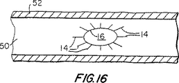
図16は、先に述べた点、すなわち、本発明に従ったコネクタまたはプラグが円形以外の断面形状を有し得ることを図示している。図16で示した特定の例では、このコネクタまたはプラグは、楕円形の断面を有し、この楕円の主軸は、実質的に、導管50の長手軸と一直線に並べられる。さらに、図16は、内側部16のいずれかまたは両方の軸末端における異なるフィンガー14が異なる長さを有し得ることを示している。図16で示した特定の例では、導管50の長手軸とさらにほぼ一直線になっているフィンガー14が、導管50の長手軸とさらにほぼ垂直のフィンガーよりも長い。異なる長さのフィンガー14を作製するために、出発チューブ10の一方または両方の軸末端は、切片12を作製する前に、適切な形状であり得るか、またはこれらのフィンガーの自由末端は、切片12を作製した後に、切り取ることができる。
【0035】
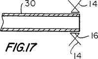
図17は、先に言及した別の可能性、すなわち、内側部16の軸方向に対向した末端から伸長しているフィンガー14が、それらの自由末端が重なり合うように、反らされセットされ得ることを図示している。このようにして作製したコネクタまたはプラグが患者に設置される場合、このフィンガー14を構成することにより、フィンガー14とその間の組織との間の接触面積、およびこれらのフィンガー間の組織の圧縮を高めるのを助ける。
【0036】
フィンガー14の曲げ堅さ(特に、内側部16の放射状の方向での)が、各フィンガーの長さに沿って、所定様式で変わるように、それらを製造するのが所望され得る。この特徴は、例えば、これらのフィンガーを送達チューブ40へと挿入するために反らしたとき、例えば、それらがほぼ円筒形状を呈するように、使用できる。それゆえ、図18は、送達チューブに挿入する前でのこの潜在的な特徴を利用したコネクタまたはプラグを示し、そして図19は、送達チューブ40に挿入した後の図18の構造を示している。図7または10(一方)と図19(他方)との比較により、図19では、フィンガー14は、内側部16の各軸末端にて、ほぼ円筒形のアレイを形成することが明らかとなる。何故なら、図18および19のフィンガーの曲げ堅さは、この結果を生じるように、変更されているからである。
【0037】
図20および21は、図18および19に関連して上で述べたように、その長さに沿ってフィンガー14の曲げ堅さを変更するための例証的な技術を示している。図20では、出発チューブ10’の壁厚は、このチューブの長さに沿って変えられて、その長さに沿って対応して厚さを変えたフィンガー14が得られる。図21では、フィンガー14は、その幅がその長さに沿って変わるように、切断される。もし所望なら、両技術(図20および21)は、組み合わせることができる。一般的に言えば、フィンガー14の相対位置は、任意の適切な様式で変更されて、フィンガー14は、任意の所望の弾性的な挙動を示すようにできる。
【0038】
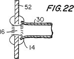
図22は、本発明に従って、天然または人工移植片導管30をコネクタに装着するための別の技術を図示している。図22で示すように、内側部16の一端にあるフィンガー14は、(例えば、穿刺することにより)移植片導管30の環状末端部を通るようにされる。このコネクタおよび移植片を、患者の身体組織壁52にある開口部を通って患者に設置した場合、これらのフィンガー14は、壁52の一面と接触するように曲がって戻るのに対して、内側部16の他端にあるフィンガー14は、壁52の他面と接触するように、曲がって戻る。
【0039】
図23は、既に簡単に述べた他の点、すなわち、本発明のコネクタの一端が、このコネクタの長手軸に対して90°以外の角度を有し得ることを図示している。図23で示した例では、このコネクタの左端は、このコネクタの長手軸に対して垂直ではない。この種のコネクタは、他の導管の長手軸に対して垂直ではない角度で、他の導管の側壁に移植片導管を接続するのに、特に適切であり得る。
【0040】
図24は、患者にてコネクタまたはプラグを展開する前に、フィンガー14を所望形状で解除可能に保持するのに使用され得る技術を例示する。この実施態様では、このコネクタまたはプラグの一端近くの各フィンガー14の自由末端部は、それを通る穴14cを有する。ワイヤ90または他の適切な材料ストランドは、これらの穴に通され、そしてこれらのフィンガーを所望状態で保持するループ(この場合、内側部16の実質的に円筒形の伸長部)に形成される。ループ90が未完成で穴14cから引き出される場合、付随したフィンガー14は、(例えば、図8または図12で示すように)、放射状に跳ね返るように、開放される。フィンガー14のこの種の解除可能な保持は、それらを完全に展開するのが望ましくなるまで、付随したフィンガーの制御を容易にするために、送達チューブ(例えば、図7または10では、チューブ40)の内側での保持に代えてまたはそれに加えて、使用され得る。例えば、フィンガー14のこのような解除可能な拘束および制御は、コネクタまたはプラグの腔内送達および展開を容易にするのに、有用であり得る。
【0041】
図25は、フィンガー14をコネクタ上に解除可能に拘束するための構造体100の他の例を示す。この場合、構造体100は、このコネクタを通って軸方向に伸長している細長チューブまたはロッドである。構造体100の一端でのある程度拡大したヘッド102は、内側部16の一端でフィンガー14の自由末端を解除可能に受容するための陥凹部104を包含する。言い換えれば、陥凹部104は、カラー106を規定しており、これは、隣接するフィンガー14の自由末端の回りに環状に伸長している。フィンガー14が、このように、陥凹部104またはカラー106で受容されるとき、それらは、外向きに放射状に跳ね返るのが防止される。しかしながら、フィンガー14が、(例えば、構造体100を、図25で示す他の要素に対して、左にシフトすることにより)、陥凹部104またはカラー106から解除される場合、これらのフィンガーは、自由に、弾力的に放射状に外向きに跳ね返る。構造体100は、次いで、(例えば、図25で見えるように、右に引き戻すことにより)、取り外され得る。ヘッド102は、さらに、フィンガー14を陥凹部104またはカラー106から解除する前に、この構造体が患者の身体組織壁を通るのを助けるための切歯および/または拡張器として作用するように、図25で示すように、鋭くされ得る。構造体100は、患者に予め設置されたガイドワイヤに沿って患者に通すように、適合され得る。例えば、構造体100は、中心に軸方向に伸長している穴または管腔を有し得、そこを通って、このようなガイドワイヤが通過し得る。中心の、軸方向に伸長しているガイド構造体は、同様に、図7で示したものと似た実施態様と共に、使用され得る。
【0042】
図26は、隣接フィンガー14間に弾性が高い材料のウエブ110(例えば、シリコーン)を含めるために、本発明に従ったコネクタの可能な改変を示している。このようなウエブ110は、内側部16のいずれかまたは両方の末端で、フィンガー14上に設けることができる。ウエブ110の可能な利点には、高い密封およびより速い凝固が挙げられる。もし望ましいなら、ウエブ110には、凝固向上材料または凝固促進材料または薬剤を添加できる。
【0043】
上で常に具体的に述べている訳ではないものの、図14〜26で示した特徴の多くは、移植片コネクタだけでなく、プラグにも適用できることが分かる。
【0044】
図27および28は、2個の最初は別個の部分10xおよび10yからコネクタを組み立てた代替実施態様を示す。部分10xおよび10yの各々は、好ましくは、図1および2で示したチューブと類似したチューブから形成される。部分10yを形成するのに使用されるチューブの直径は、部分10xを形成するのに使用されるチューブの直径より、ある程度大きい。フィンガー14xおよび14yは、各チューブの1軸末端部で形成される。穴120xおよび120yは、各チューブの他の軸末端部で形成される。内側部16xおよび16yは、各チューブにて、フィンガー14とそのチューブの穴120との間で残る。各チューブ上のフィンガー14は、他の実施態様に対して、上で記述したように処理される(すなわち、これらのフィンガーは、放射状に反らされて、その状態でセットされる)。
【0045】
構造体10xおよび10yは、次いで、図28で示すように、移植片導管30の末端上で組み立てられる。特に、構造体10yの穿孔した内側部は、移植片導管30の外側の回りで、実質的に同心円状に配置されるのに対して、一方、構造体10xは、この移植片導管の内側で、実質的に同心円状に配置される。構造体10xおよび10yは、それらのフィンガー14が移植片導管30の長手軸に沿って対向するように、配向される。構造体10x、10yおよび30は、(例えば、放射状に隣接した穴120xおよび120yならびに導管30の介在壁材料を通る縫合130によって)、共に固定される。縫合の代わりにまたはそれに加えて、構造体10x、10yおよび30は、これらの部品を共に保持するのを助けるために、共にプレス嵌めされ得、および/または接着剤が使用され得る。フィンガー14は、導管30の長手軸に実質的に平行でかつ穴120の領域から離れて(もし、それが、導管30上での構造体10xおよび10yの組み立てを容易にするなら)、弾力的に反らされ得る。構造体10x、10yおよび30のアセンブリは、他のコネクタ実施態様のいずれかについて上で記述したのと同じ様式で、患者の移植部位にて、送達され設置され得る。
【0046】
図27および28で示した型のコネクタは、たとえ、ある部品10xが導管30の内側にあったとしても、その部品が、30xで示されるように、導管に放射状に引っ込められ得、それにより、導管30およびこのコネクタを通る、流体流れ用の実質的に滑らかな通路が残るという利点を有し得る。このような滑らかな通路は、この流体流れの閉塞または攪乱(例えば、乱流を引き起こすことによる)を回避するような目的のために、望ましい。30xにおける陥凹部は、部品10xおよび10yの管状部分間にある組織をクランプ留めすることにより、作製され得る。
【0047】
ある用途では、移植片コネクタにて、10xまたは10yのような構造体1個だけを使用することが可能であり得る。例えば、図28から構造体10yをなくすことは可能であり得る。さらに、構造体10yを図28からなくす場合、図28で示したアセンブリは、さらに、構造体10xを移植片導管30の末端の内側よりもむしろ外側に配置することらにより、改変され得る。他のコネクタ実施態様について上述した改変および/または強化のいずれかはまた、図27および28で示した型のコネクタに適用され得る。
【0048】
図27および28で示した型の構造体はまた、本発明に従ったプラグを作製するのに、使用可能である。例えば、10xのような構造体は、一般に、図28で示した10yのような構造体と共に(しかし、移植片導管30なしで)、組み立てられ得る。このアセンブリの内部は、一般に、図9の70で示すように、プラギング材料または構造体により閉塞されて、完成したプラグを作製する。このようなプラグは、他のプラグ実施態様のいずれかについて上で記述したように、設置される。
【0049】
前述のことは、本発明の原理の例示にすぎず、本発明の範囲および精神から逸脱することなく、当業者により、さらに他の改変を行い得ることが理解される。例えば、本明細書中で言及した種々の材料および寸法は、例にすぎず、他の材料および寸法が、所望であれば、使用され得る。本発明の範囲内の改変の他の例として、図1および2のチューブのようなチューブを用いた開始の代替物として、チューブ10に適切な任意の材料のウエブと共に開始し得る。このウエブの2個の対向した辺縁部は、次いで、非常に多くの実質的に平行な位置で、(ある程度、図3の切片12のように)切断されて、未切断中間ウエブ部が残る。中間ウエブ部は、次いで、例えば、得られたシームを結合してまたは結合せずに、それを心棒の回りで形成することにより、中間チューブ部に(図3での16のように)形成される。この構造体は、次いで、実質的に、図3で示すようであり、さらに処理されて、引き続く図のいずれかに関連して上で記述したようなコネクタまたはプラグを作製するのに、使用され得る。図27および28で示した型の実施態様には、チューブ出発構造体よりもむしろ類似のウエブが使用され得る。
【図面の簡単な説明】
【図1】 図1は、本発明の構造体用の出発部品の例証的な実施態様の側面立面図である。
【図2】 図2は、図1の部品の末端立面図である。
【図3】 図3は、本発明に従ったいくつかの処理後の図1部品の側面立面図である。
【図4】 図4は、本発明に従ったさらなる処理後の図3部品の断面図である。
【図5】 図5は、図4部品の末端立面図である。
【図6】 図6は、図4部品を移植片導管用のコネクタとして使用できるように、この移植片導管を付け加えた、図4部品の側面立面略図である。
【図7】 図7は、患者に図6アセンブリを設置する際に使用するための例証的な装置での図6アセンブリの部分切り欠き側面立面略図である。
【図8】 図8は、図6アセンブリを患者に設置するための図7装置の使用を図示している。
【図9】 図9は、図4部品をプラグとして使用できるように、付け加えられたプラグ材料または構造体を備える、図4部品の断面略図である。
【図10】 図10は、図7と類似の図であるが、図9のプラグ実施態様用の図である。
【図11】 図11は、図8とある程度似た図であるが、図9および10のプラグ実施態様用の図である。
【図12】 図12は、図11とある程度似た別の図であるが、これは、図9で示した型の完全に設置したプラグを示す。
【図13】 図13は、図3と類似した別の図であり、これは、本発明に従った図3型構造体の例証的な改変を示す。
【図14】 図14は、図4の一部と類似した別の図であり、これは、本発明に従った図4型構造体の例証的な改変を示す。
【図15】 図15は、図8とある程度似た断面図であり、これは、本発明に従った例証的な改変を示す。
【図16】 図16は、本発明に従った他の例証的な改変をさらに示す断面略図である。
【図17】 図17は、図6で示したアセンブリに類似したアセンブリを示す断面略図であるが、これは、本発明に従った例証的な改変を伴う。
【図18】 図18は、図4とある程度似た断面略図であり、これは、本発明に従った例証的な改変を説明する際に有用である。
【図19】 図19は、図18の改変構造体用の図7または図10にある程度似た図である。
【図20】 図20は、図18および19で図示した型の実施態様用の例証的な前駆体構造体を示す断面略図である。
【図21】 図21は、図18および19で図示した型の実施態様用の別の例証的な前駆体構造体を示す立面略図である。
【図22】 図22は、図15に類似した断面略図であり、これは、本発明に従った他の例証的な改変を示す。
【図23】 図23は、図3と類似した立面略図であり、これは、本発明に従ったさらに例証的な改変を示す。
【図24】 図24は、図3と類似した別の立面略図であり、これは、本発明に従ったなおさらに例証的な改変を示す。
【図25】 図25は、図7で示した型の装置の例証的な代替物を示す断面略図である。
【図26】 図26は、本発明に従った構造体の別の可能な改変を図示している立面略図である。
【図27】 図27は、図3にある程度似た立面略図であり、これは、本発明の別の例証的な実施態様を示す。
【図28】 図28は、図27で示した型の装置の使用を図示している断面略図である。[0001]
(Background of the Invention)
The present invention relates to a structure that can be used to make a connection between a tubular medical implant and a patient's tubular body conduit. The structure of the present invention may alternatively be configured for use as a medical plug (eg, for closing an atrial or ventricular septal defect). The invention also relates to a method of making and using the structure.
[0002]
Tubular grafts are often required in medical procedures. For example, a coronary bypass procedure is between an opening formed in the side wall of the aorta and an opening formed in the side wall of the coronary artery, which is downstream from the obstruction or obstruction in that artery. Placing a tubular graft. Each end of the graft must be connected to the side wall of either the aorta or coronary artery. Each such connection must be fluid-tight by extending annularly around the end associated with the graft conduit so that blood does not leak. One common method of making such a connection is by suturing. However, making such a connection by suturing is very difficult and time consuming, and the resulting performance depends on the skill of the physician. There is also an increasing interest in less invasive procedures, which tend to impose restrictions on physician access to sites where graft connections must be made, It is difficult or even impossible to use sutures to make such a connection (eg, Goldstein et al. US patent application Ser. No. 08 / 745,618 filed Nov. 7, 1996; 1997 Sullivan et al., US patent application Ser. No. 08 / 844,992, filed on Apr. 23, 1997; and Sullivan et al., US patent application Ser. No. 08 / 869,808, filed Jun. 5, 1997; The entire contents are hereby fully incorporated by reference). Various types of mechanical connectors have been developed to reduce or eliminate the need for stitching, with regard to ease and speed of use, ease of manufacture, strength and durability of the resulting connection, etc. There is a constant need for improvements to such mechanical connectors.
[0003]
Plugs are also required for various medical procedures. For example, it may be necessary to plug an atrial or ventricular septal defect in the neonatal heart. Again, there is a continuing need for improvements to plugs that can be installed easily and quickly using minimally invasive procedures.
[0004]
In view of the foregoing, it is an object of the present invention to provide an improved and simplified graft connector.
[0005]
Another object of the present invention is to provide an improved and simplified medical plug.
[0006]
It is yet another object of the present invention to provide an improved and simplified method for manufacturing a structure that can be used as either a medical graft connector or a plug.
[0007]
Yet another object of the present invention is to provide an improved and simplified method for installing a medical graft connector or plug.
[0008]
(Summary of the Invention)
These and other objects of the present invention are preferably by providing a connector or plug structure formed starting from a tube of a highly elastic material (eg, nickel and titanium alloy (Nitinol) metal). This is accomplished in accordance with the principles of the present invention. Each end of the tube is circumferentially spaced around the tube and is cut substantially axially at a number of locations to create a plurality of fingers, which are Extending substantially axially from each end of the remaining inner portion. The fingers at each end of the inner portion are then warped to extend substantially radially from the inner portion, and the fingers are set in the warped state (eg, by heat treatment). Is done. In order to use this structure as a graft connector, the inner portion is mounted substantially coaxially at the distal end of the graft conduit. In order to use the structure as a plug, the inner part of the tube is filled with a suitable plugging material or structure.
[0009]
In order to place the graft connector or plug in the patient, the fingers are in their initial state at each axial end of the inner part (in this state, the fingers are at the inner end of the inner part). To substantially axially). This structure can then be inserted into a delivery tube, which can maintain these fingers in their substantially axially extending state. The delivery tube can then be inserted through an opening in the side wall of the patient's tubular human conduit to which the end of the graft conduit is to be attached or through an opening in the patient's tissue structure to be occluded. . The delivery conduit can then be removed from around the connector or plug structure. This releases the fingers from each end of the inner part and rebounds on the opposite side of each tissue structure in which the connection is to be made or to which the plug is to be applied.
[0010]
In some cases, the fingers can be formed only at one end of the starting tube. A connector is then provided using two such tubes concentric with each other and with the graft conduit. In such an assembly, the fingers on these two tubes generally extend from opposite axial ends of the assembly. Two such tubes can be used in the same way to make a plug, but in this case the graft conduit is omitted and the interior of the structure is plugging material or structure Filled with.
[0011]
In place of or in addition to the use of a delivery tube, another structure is removably disposed around these fingers to releasably retain the fingers substantially parallel to the longitudinal axis of the connector or plug. Can be done. Examples of such other structures include a collar or strand of material (eg, wire or suture material).
[0012]
Further features of the invention, its nature and various advantages will be more apparent from the accompanying drawings and the following detailed description of the preferred embodiments.
[0013]
Detailed Description of Preferred Embodiments
An exemplary starting part of the connector or plug structure of the present invention is a
[0014]
The first step of treating the
[0015]
The next step is to warp the
[0016]
When the
[0017]
If the
[0018]
6-8 illustrate the use of a structure of the type shown in FIGS. 4 and 5 to provide the
[0019]
In the illustrative embodiment shown in FIG. 6, the axial end of the
[0020]
The next step in using the
[0021]
In using the assembly shown in FIG. 7, the next step is to deliver the delivery tube through an opening in the side wall of the patient's tubular body conduit (50 in FIG. 8) to which the
[0022]
The next step is illustrated in FIG. 8 and involves withdrawing the
[0023]
Although FIGS. 7 and 8 illustrate insertion of the
[0024]
FIG. 9 shows an alternative embodiment that is adapted to use a structure of the type shown in FIGS. In this alternative, the
[0025]
The next step in using the
[0026]
The next step is to pull the
[0027]
As with the
[0028]
The manufacture of the connector or plug structure is greatly facilitated by the fact that the
[0029]
If desired, the
[0030]
Due to the perforation of the
[0031]
While the depicted connector and plug embodiments are circular, other shapes (eg, oval, polygonal, etc.) are equally possible. Similarly, the end of the
[0032]
FIG. 14 shows that the free ends of
[0033]
FIG. 15 shows the free ends of the
[0034]
FIG. 16 illustrates the point mentioned above, that is, a connector or plug according to the present invention may have a cross-sectional shape other than circular. In the particular example shown in FIG. 16, the connector or plug has an elliptical cross section, and the major axis of the ellipse is substantially aligned with the longitudinal axis of the
[0035]
FIG. 17 shows another possibility mentioned above, namely that the
[0036]
It may be desirable to manufacture the
[0037]
20 and 21 illustrate an exemplary technique for changing the bending stiffness of the
[0038]
FIG. 22 illustrates another technique for attaching a natural or
[0039]
FIG. 23 illustrates another point already briefly described, namely that one end of the connector of the present invention may have an angle other than 90 ° with respect to the longitudinal axis of the connector. In the example shown in FIG. 23, the left end of the connector is not perpendicular to the longitudinal axis of the connector. This type of connector may be particularly suitable for connecting a graft conduit to the side wall of another conduit at an angle that is not perpendicular to the longitudinal axis of the other conduit.
[0040]
FIG. 24 illustrates a technique that can be used to releasably hold the
[0041]
FIG. 25 shows another example of a
[0042]
FIG. 26 illustrates a possible modification of the connector according to the present invention to include a highly elastic web 110 (eg, silicone) between
[0043]
Although not specifically described above, it will be appreciated that many of the features shown in FIGS. 14-26 can be applied to plugs as well as graft connectors.
[0044]
Figures 27 and 28 show an alternative embodiment in which the connector is assembled from two initially
[0045]
[0046]
A connector of the type shown in FIGS. 27 and 28, even if a
[0047]
In certain applications, it may be possible to use only one structure, such as 10x or 10y, in the graft connector. For example, it may be possible to eliminate
[0048]
A structure of the type shown in FIGS. 27 and 28 can also be used to make a plug according to the present invention. For example, a structure such as 10x can generally be assembled with a structure such as 10y shown in FIG. 28 (but without graft conduit 30). The interior of this assembly is generally occluded by plugging material or structure, as shown at 70 in FIG. 9, to create a finished plug. Such plugs are installed as described above for any of the other plug embodiments.
[0049]
It will be understood that the foregoing is only illustrative of the principles of the invention and that other modifications can be made by those skilled in the art without departing from the scope and spirit of the invention. For example, the various materials and dimensions mentioned herein are only examples, and other materials and dimensions can be used if desired. As another example of a modification within the scope of the present invention, as an alternative to starting with a tube such as the tube of FIGS. 1 and 2, one can start with a web of any material suitable for
[Brief description of the drawings]
FIG. 1 is a side elevational view of an exemplary embodiment of a starting part for a structure of the present invention.
2 is an end elevation view of the component of FIG.
FIG. 3 is a side elevational view of the FIG. 1 part after several treatments in accordance with the present invention.
FIG. 4 is a cross-sectional view of the FIG. 3 component after further processing in accordance with the present invention.
FIG. 5 is an end elevation view of the FIG. 4 component.
FIG. 6 is a side elevation schematic view of the FIG. 4 part with the graft conduit added so that the FIG. 4 part can be used as a connector for the graft conduit.
FIG. 7 is a partially cutaway side elevational schematic view of the FIG. 6 assembly with an illustrative apparatus for use in installing the FIG. 6 assembly on a patient.
FIG. 8 illustrates the use of the FIG. 7 device to install the FIG. 6 assembly on a patient.
9 is a schematic cross-sectional view of the FIG. 4 component with added plug material or structure so that the FIG. 4 component can be used as a plug.
FIG. 10 is a view similar to FIG. 7 but for the plug embodiment of FIG. 9;
11 is a view similar to FIG. 8 to some extent, but for the plug embodiment of FIGS. 9 and 10. FIG.
FIG. 12 is another view somewhat similar to FIG. 11 but showing a fully installed plug of the type shown in FIG.
FIG. 13 is another view similar to FIG. 3, which illustrates an exemplary modification of the FIG. 3 structure according to the present invention.
FIG. 14 is another view similar to a portion of FIG. 4, which illustrates an exemplary modification of the FIG. 4 type structure in accordance with the present invention.
FIG. 15 is a cross-sectional view somewhat similar to FIG. 8, which illustrates an exemplary modification in accordance with the present invention.
FIG. 16 is a schematic cross-sectional view further illustrating another exemplary modification in accordance with the present invention.
FIG. 17 is a schematic cross-sectional view showing an assembly similar to the assembly shown in FIG. 6, but with an exemplary modification in accordance with the present invention.
FIG. 18 is a cross-sectional schematic that is somewhat similar to FIG. 4, which is useful in describing an exemplary modification in accordance with the present invention.
FIG. 19 is a view somewhat similar to FIG. 7 or FIG. 10 for the modified structure of FIG.
FIG. 20 is a schematic cross-sectional view illustrating an exemplary precursor structure for an embodiment of the type illustrated in FIGS. 18 and 19. FIG.
FIG. 21 is a schematic elevational view showing another exemplary precursor structure for an embodiment of the type illustrated in FIGS. 18 and 19. FIG.
FIG. 22 is a schematic cross-sectional view similar to FIG. 15, which shows another illustrative modification in accordance with the present invention.
FIG. 23 is an elevational schematic similar to FIG. 3, which shows a further exemplary modification in accordance with the present invention.
FIG. 24 is another elevation schematic similar to FIG. 3, which shows a still further illustrative modification in accordance with the present invention.
FIG. 25 is a schematic cross-sectional view showing an illustrative alternative to an apparatus of the type shown in FIG.
FIG. 26 is an elevational diagram illustrating another possible modification of the structure according to the present invention.
FIG. 27 is an elevational schematic diagram somewhat similar to FIG. 3, which illustrates another exemplary embodiment of the present invention.
FIG. 28 is a schematic cross-sectional view illustrating the use of an apparatus of the type shown in FIG.
Claims (25)
長手軸を有する内側部分;
該内側部分に設けられる第1および第2のフィンガーの組であって、該フィンガーは、配備時に前記内側部分の軸から離れる方向に実質的に放射状に外側に反った状態まで延び得る、第1および第2のフィンガーの組、
を備え、該第1および第2の組は、該軸上で互いから離れて軸の距離だけ間隔を開けられており、そしてここでフィンガーのただ1つの組が、該フィンガーの隣接する組の間の材料のウェブにより覆われている、デバイス。A device for use in closing a septal defect, the device comprising:
An inner portion having a longitudinal axis;
A pair of first and second fingers provided on the inner portion, wherein the fingers can extend substantially radially outwardly away from the axis of the inner portion during deployment; And a second pair of fingers,
The first and second sets are spaced apart from each other on the axis by an axial distance, wherein only one set of fingers is adjacent to the adjacent set of fingers A device covered by a web of material between.
内側部分に同軸状に配置される第1および第2のフィンガーの組であって、配備時に該内側部分の軸から離れる方向に実質的に放射状に外側に反った状態まで延びるように構成されている、第1および第2のフィンガーの組、
を備え、そしてここでフィンガーのただ1つの組が、該フィンガーの隣接する組の間の材料のウェブにより覆われており、そしてここで縫合糸が第1の組のフィンガーを第2の組のフィンガーと一緒に固定する、デバイス。A device for use in closing a septal defect, the device comprising:
A pair of first and second fingers coaxially disposed on the inner portion, wherein the first and second fingers are configured to extend substantially radially outwardly in a direction away from the axis of the inner portion during deployment; A pair of first and second fingers,
And wherein only one set of fingers is covered by a web of material between adjacent sets of fingers, and wherein the suture connects the first set of fingers to the second set of fingers. Device that is fixed together with fingers.
Applications Claiming Priority (3)
| Application Number | Priority Date | Filing Date | Title |
|---|---|---|---|
| US1672198A | 1998-01-30 | 1998-01-30 | |
| US09/016,721 | 1998-01-30 | ||
| PCT/US1998/026845 WO1999038454A2 (en) | 1998-01-30 | 1998-12-18 | Medical graft connector or plug structures, and methods of making and installing same |
Related Child Applications (1)
| Application Number | Title | Priority Date | Filing Date |
|---|---|---|---|
| JP2008178318A Division JP4767292B2 (en) | 1998-01-30 | 2008-07-08 | Device for use in closing a septal defect |
Publications (3)
| Publication Number | Publication Date |
|---|---|
| JP2002501778A JP2002501778A (en) | 2002-01-22 |
| JP2002501778A5 JP2002501778A5 (en) | 2006-02-02 |
| JP4187411B2 true JP4187411B2 (en) | 2008-11-26 |
Family
ID=21778607
Family Applications (2)
| Application Number | Title | Priority Date | Filing Date |
|---|---|---|---|
| JP2000529190A Expired - Lifetime JP4187411B2 (en) | 1998-01-30 | 1998-12-18 | Device for use in closing a septal defect |
| JP2008178318A Expired - Lifetime JP4767292B2 (en) | 1998-01-30 | 2008-07-08 | Device for use in closing a septal defect |
Family Applications After (1)
| Application Number | Title | Priority Date | Filing Date |
|---|---|---|---|
| JP2008178318A Expired - Lifetime JP4767292B2 (en) | 1998-01-30 | 2008-07-08 | Device for use in closing a septal defect |
Country Status (7)
| Country | Link |
|---|---|
| US (3) | US6391036B1 (en) |
| EP (2) | EP1051128B1 (en) |
| JP (2) | JP4187411B2 (en) |
| AT (1) | ATE320229T1 (en) |
| AU (1) | AU1923999A (en) |
| DE (1) | DE69833882T2 (en) |
| WO (1) | WO1999038454A2 (en) |
Families Citing this family (321)
| Publication number | Priority date | Publication date | Assignee | Title |
|---|---|---|---|---|
| US20010029383A1 (en) * | 1996-07-24 | 2001-10-11 | Solem Jan Otto | Connecting apparatus and method |
| US5976178A (en) * | 1996-11-07 | 1999-11-02 | Vascular Science Inc. | Medical grafting methods |
| US6036702A (en) * | 1997-04-23 | 2000-03-14 | Vascular Science Inc. | Medical grafting connectors and fasteners |
| FR2768324B1 (en) | 1997-09-12 | 1999-12-10 | Jacques Seguin | SURGICAL INSTRUMENT FOR PERCUTANEOUSLY FIXING TWO AREAS OF SOFT TISSUE, NORMALLY MUTUALLY REMOTE, TO ONE ANOTHER |
| NL1007349C2 (en) * | 1997-10-24 | 1999-04-27 | Suyker Wilhelmus Joseph Leonardus | System for the mechanical production of anastomoses between hollow structures; as well as device and applicator for use therewith. |
| US6176864B1 (en) * | 1998-03-09 | 2001-01-23 | Corvascular, Inc. | Anastomosis device and method |
| US20040049221A1 (en) * | 1998-05-29 | 2004-03-11 | By-Pass, Inc. | Method and apparatus for forming apertures in blood vessels |
| US20050101983A1 (en) * | 1998-05-29 | 2005-05-12 | By-Pass,Inc. | Method and apparatus for forming apertures in blood vessels |
| US20040087985A1 (en) * | 1999-03-19 | 2004-05-06 | Amir Loshakove | Graft and connector delivery |
| US20050283188A1 (en) * | 1998-05-29 | 2005-12-22 | By-Pass, Inc. | Vascular closure device |
| US6726704B1 (en) | 1998-05-29 | 2004-04-27 | By-Pass, Inc. | Advanced closure device |
| US20040073247A1 (en) * | 1998-05-29 | 2004-04-15 | By-Pass, Inc. | Method and apparatus for forming apertures in blood vessels |
| US7396359B1 (en) | 1998-05-29 | 2008-07-08 | Bypass, Inc. | Vascular port device |
| US6613059B2 (en) | 1999-03-01 | 2003-09-02 | Coalescent Surgical, Inc. | Tissue connector apparatus and methods |
| US6641593B1 (en) | 1998-06-03 | 2003-11-04 | Coalescent Surgical, Inc. | Tissue connector apparatus and methods |
| US6945980B2 (en) | 1998-06-03 | 2005-09-20 | Medtronic, Inc. | Multiple loop tissue connector apparatus and methods |
| JP2002518082A (en) | 1998-06-10 | 2002-06-25 | コンバージ メディカル, インコーポレイテッド | Sutureless anastomosis system |
| US6461320B1 (en) * | 1998-08-12 | 2002-10-08 | Cardica, Inc. | Method and system for attaching a graft to a blood vessel |
| US6152937A (en) * | 1998-11-06 | 2000-11-28 | St. Jude Medical Cardiovascular Group, Inc. | Medical graft connector and methods of making and installing same |
| US8118822B2 (en) | 1999-03-01 | 2012-02-21 | Medtronic, Inc. | Bridge clip tissue connector apparatus and methods |
| AU3729400A (en) * | 1999-03-09 | 2000-09-28 | St. Jude Medical Cardiovascular Group, Inc. | Medical grafting methods and apparatus |
| US6695859B1 (en) | 1999-04-05 | 2004-02-24 | Coalescent Surgical, Inc. | Apparatus and methods for anastomosis |
| US6752813B2 (en) | 1999-04-09 | 2004-06-22 | Evalve, Inc. | Methods and devices for capturing and fixing leaflets in valve repair |
| US10327743B2 (en) | 1999-04-09 | 2019-06-25 | Evalve, Inc. | Device and methods for endoscopic annuloplasty |
| US7811296B2 (en) | 1999-04-09 | 2010-10-12 | Evalve, Inc. | Fixation devices for variation in engagement of tissue |
| US8216256B2 (en) * | 1999-04-09 | 2012-07-10 | Evalve, Inc. | Detachment mechanism for implantable fixation devices |
| US7226467B2 (en) | 1999-04-09 | 2007-06-05 | Evalve, Inc. | Fixation device delivery catheter, systems and methods of use |
| US20040044350A1 (en) * | 1999-04-09 | 2004-03-04 | Evalve, Inc. | Steerable access sheath and methods of use |
| DE60045096D1 (en) | 1999-04-09 | 2010-11-25 | Evalve Inc | METHOD AND DEVICE FOR HEART LAPSE REPERATION |
| WO2000064380A1 (en) | 1999-04-23 | 2000-11-02 | St. Jude Medical Cardiovascular Group, Inc. | Artificial heart valve attachment apparatus |
| EP1665990A3 (en) * | 1999-05-13 | 2006-06-21 | St.Jude Medical ATG, Inc. | Septal defect closure device |
| ATE314010T1 (en) * | 1999-05-13 | 2006-01-15 | St Jude Medical Atg Inc | CLOSING DEVICE OF A SEPTUM DAMAGE |
| US6673088B1 (en) | 1999-05-18 | 2004-01-06 | Cardica, Inc. | Tissue punch |
| US6428550B1 (en) * | 1999-05-18 | 2002-08-06 | Cardica, Inc. | Sutureless closure and deployment system for connecting blood vessels |
| AU5143000A (en) * | 1999-05-18 | 2000-12-05 | Vascular Innovations, Inc. | Implantable medical device such as an anastomosis device |
| US6790229B1 (en) | 1999-05-25 | 2004-09-14 | Eric Berreklouw | Fixing device, in particular for fixing to vascular wall tissue |
| AU5317500A (en) * | 1999-06-04 | 2000-12-28 | St. Jude Medical Cardiovascular Group, Inc. | Medical grafting apparatus and methods |
| US6991643B2 (en) | 2000-12-20 | 2006-01-31 | Usgi Medical Inc. | Multi-barbed device for retaining tissue in apposition and methods of use |
| US20030070676A1 (en) * | 1999-08-05 | 2003-04-17 | Cooper Joel D. | Conduits having distal cage structure for maintaining collateral channels in tissue and related methods |
| US6702828B2 (en) * | 1999-09-01 | 2004-03-09 | Converge Medical, Inc. | Anastomosis system |
| US8529583B1 (en) | 1999-09-03 | 2013-09-10 | Medtronic, Inc. | Surgical clip removal apparatus |
| US7662161B2 (en) | 1999-09-13 | 2010-02-16 | Rex Medical, L.P | Vascular hole closure device |
| CA2381818C (en) * | 1999-09-13 | 2009-08-04 | Rex Medical, L.P. | Vascular closure |
| US6926730B1 (en) | 2000-10-10 | 2005-08-09 | Medtronic, Inc. | Minimally invasive valve repair procedure and apparatus |
| US6458153B1 (en) * | 1999-12-31 | 2002-10-01 | Abps Venture One, Ltd. | Endoluminal cardiac and venous valve prostheses and methods of manufacture and delivery thereof |
| US6602263B1 (en) | 1999-11-30 | 2003-08-05 | St. Jude Medical Atg, Inc. | Medical grafting methods and apparatus |
| DE10000137A1 (en) * | 2000-01-04 | 2001-07-12 | Pfm Prod Fuer Die Med Ag | Implantate for closing defect apertures in human or animal bodies, bearing structure of which can be reversed from secondary to primary form by elastic force |
| US8758400B2 (en) | 2000-01-05 | 2014-06-24 | Integrated Vascular Systems, Inc. | Closure system and methods of use |
| US6391048B1 (en) | 2000-01-05 | 2002-05-21 | Integrated Vascular Systems, Inc. | Integrated vascular device with puncture site closure component and sealant and methods of use |
| US7842068B2 (en) | 2000-12-07 | 2010-11-30 | Integrated Vascular Systems, Inc. | Apparatus and methods for providing tactile feedback while delivering a closure device |
| US6461364B1 (en) | 2000-01-05 | 2002-10-08 | Integrated Vascular Systems, Inc. | Vascular sheath with bioabsorbable puncture site closure apparatus and methods of use |
| US9579091B2 (en) | 2000-01-05 | 2017-02-28 | Integrated Vascular Systems, Inc. | Closure system and methods of use |
| NL1014364C2 (en) * | 2000-02-11 | 2001-08-14 | Surgical Innovations Vof | Endoluminal grafting method for treating body conduit e.g. artery, aorta, involves introducing side graft into side branch through primary graft, afterwhich side graft is fixed to primary graft |
| NL1014559C2 (en) * | 2000-02-11 | 2001-08-14 | Surgical Innovations Vof | Umbrella stent. |
| AU2001244497A1 (en) * | 2000-03-20 | 2001-10-03 | By-Pass, Inc. | Transvascular bypass method and system |
| CA2403119A1 (en) * | 2000-03-20 | 2001-09-27 | By-Pass, Inc. | Graft delivery system |
| US6551332B1 (en) | 2000-03-31 | 2003-04-22 | Coalescent Surgical, Inc. | Multiple bias surgical fastener |
| US6616686B2 (en) | 2000-09-08 | 2003-09-09 | James Coleman | Surgical staples and methods for stapling |
| US6626918B1 (en) * | 2000-10-06 | 2003-09-30 | Medical Technology Group | Apparatus and methods for positioning a vascular sheath |
| US6918917B1 (en) * | 2000-10-10 | 2005-07-19 | Medtronic, Inc. | Minimally invasive annuloplasty procedure and apparatus |
| US6776785B1 (en) * | 2000-10-12 | 2004-08-17 | Cardica, Inc. | Implantable superelastic anastomosis device |
| US6966917B1 (en) * | 2000-11-09 | 2005-11-22 | Innovation Interventional Technologies B.V. | Deformable connector for mechanically connecting hollow structures |
| US6554764B1 (en) | 2000-11-13 | 2003-04-29 | Cardica, Inc. | Graft vessel preparation device and methods for using the same |
| US8690910B2 (en) | 2000-12-07 | 2014-04-08 | Integrated Vascular Systems, Inc. | Closure device and methods for making and using them |
| US6623510B2 (en) | 2000-12-07 | 2003-09-23 | Integrated Vascular Systems, Inc. | Closure device and methods for making and using them |
| US7211101B2 (en) | 2000-12-07 | 2007-05-01 | Abbott Vascular Devices | Methods for manufacturing a clip and clip |
| US7905900B2 (en) | 2003-01-30 | 2011-03-15 | Integrated Vascular Systems, Inc. | Clip applier and methods of use |
| US6695867B2 (en) | 2002-02-21 | 2004-02-24 | Integrated Vascular Systems, Inc. | Plunger apparatus and methods for delivering a closure device |
| FR2822370B1 (en) * | 2001-03-23 | 2004-03-05 | Perouse Lab | TUBULAR ENDOPROSTHESIS COMPRISING A DEFORMABLE RING AND REQUIRED OF INTERVENTION FOR ITS IMPLANTATION |
| US20050148925A1 (en) | 2001-04-20 | 2005-07-07 | Dan Rottenberg | Device and method for controlling in-vivo pressure |
| US20110144661A1 (en) * | 2001-04-24 | 2011-06-16 | Houser Russell A | Tissue closure devices, device and systems for delivery, kits and methods therefor |
| US8961541B2 (en) | 2007-12-03 | 2015-02-24 | Cardio Vascular Technologies Inc. | Vascular closure devices, systems, and methods of use |
| US8992567B1 (en) | 2001-04-24 | 2015-03-31 | Cardiovascular Technologies Inc. | Compressible, deformable, or deflectable tissue closure devices and method of manufacture |
| US20080109030A1 (en) | 2001-04-24 | 2008-05-08 | Houser Russell A | Arteriotomy closure devices and techniques |
| US20020173803A1 (en) * | 2001-05-01 | 2002-11-21 | Stephen Ainsworth | Self-closing surgical clip for tissue |
| WO2002091952A2 (en) * | 2001-05-14 | 2002-11-21 | St. Jude Medical Atg, Inc. | Medical grafting methods and apparatus |
| US7338514B2 (en) | 2001-06-01 | 2008-03-04 | St. Jude Medical, Cardiology Division, Inc. | Closure devices, related delivery methods and tools, and related methods of use |
| IES20010547A2 (en) | 2001-06-07 | 2002-12-11 | Christy Cummins | Surgical Staple |
| US7993365B2 (en) * | 2001-06-08 | 2011-08-09 | Morris Innovative, Inc. | Method and apparatus for sealing access |
| US20060004408A1 (en) * | 2001-06-08 | 2006-01-05 | Morris Edward J | Method and apparatus for sealing access |
| US20070038244A1 (en) * | 2001-06-08 | 2007-02-15 | Morris Edward J | Method and apparatus for sealing access |
| NL1018302C1 (en) * | 2001-06-15 | 2002-07-17 | Eric Berreklouw | Applicator for a prosthesis, assembly comprising such an applicator and tensioning system for loading such an applicator. |
| KR100891045B1 (en) * | 2001-06-20 | 2009-03-31 | 파크 메디칼 엘엘씨 | Anastomotic device |
| US7115136B2 (en) * | 2001-06-20 | 2006-10-03 | Park Medical Llc | Anastomotic device |
| CN101810521B (en) | 2001-08-27 | 2015-05-13 | 辛尼科有限责任公司 | Satiation devices and methods |
| US6845776B2 (en) | 2001-08-27 | 2005-01-25 | Richard S. Stack | Satiation devices and methods |
| US6675809B2 (en) * | 2001-08-27 | 2004-01-13 | Richard S. Stack | Satiation devices and methods |
| US7097665B2 (en) | 2003-01-16 | 2006-08-29 | Synecor, Llc | Positioning tools and methods for implanting medical devices |
| US6985235B2 (en) * | 2001-08-30 | 2006-01-10 | Micron Optics, Inc. | Cascaded fiber fabry-perot filters |
| US7708712B2 (en) | 2001-09-04 | 2010-05-04 | Broncus Technologies, Inc. | Methods and devices for maintaining patency of surgically created channels in a body organ |
| US20070129755A1 (en) * | 2005-12-05 | 2007-06-07 | Ovalis, Inc. | Clip-based systems and methods for treating septal defects |
| US7182771B1 (en) * | 2001-12-20 | 2007-02-27 | Russell A. Houser | Vascular couplers, techniques, methods, and accessories |
| US20030144578A1 (en) * | 2002-01-25 | 2003-07-31 | Koster J. Kenneth | Anastomosis anchoring device and method |
| US7048754B2 (en) | 2002-03-01 | 2006-05-23 | Evalve, Inc. | Suture fasteners and methods of use |
| US7146984B2 (en) | 2002-04-08 | 2006-12-12 | Synecor, Llc | Method and apparatus for modifying the exit orifice of a satiation pouch |
| CA2482935A1 (en) * | 2002-04-19 | 2003-10-30 | Broncus Technologies, Inc. | Devices for maintaining surgically created openings |
| US7976564B2 (en) | 2002-05-06 | 2011-07-12 | St. Jude Medical, Cardiology Division, Inc. | PFO closure devices and related methods of use |
| CA2488688A1 (en) | 2002-06-04 | 2003-12-11 | Christy Cummins | Blood vessel closure clip and delivery device |
| US6666873B1 (en) | 2002-08-08 | 2003-12-23 | Jack L. Cassell | Surgical coupler for joining tubular and hollow organs |
| AU2002950736A0 (en) * | 2002-08-13 | 2002-09-12 | Mark Alexander John Newman | Occlusion device and method of performing an anastomosis |
| US8066724B2 (en) | 2002-09-12 | 2011-11-29 | Medtronic, Inc. | Anastomosis apparatus and methods |
| US20060025788A1 (en) * | 2002-09-25 | 2006-02-02 | By-Pass, Inc. | Anastomotic leg arrangement |
| US8105345B2 (en) | 2002-10-04 | 2012-01-31 | Medtronic, Inc. | Anastomosis apparatus and methods |
| US8905937B2 (en) | 2009-02-26 | 2014-12-09 | Integrated Vascular Systems, Inc. | Methods and apparatus for locating a surface of a body lumen |
| US8758398B2 (en) | 2006-09-08 | 2014-06-24 | Integrated Vascular Systems, Inc. | Apparatus and method for delivering a closure element |
| US8398656B2 (en) | 2003-01-30 | 2013-03-19 | Integrated Vascular Systems, Inc. | Clip applier and methods of use |
| US8202293B2 (en) | 2003-01-30 | 2012-06-19 | Integrated Vascular Systems, Inc. | Clip applier and methods of use |
| US8821534B2 (en) | 2010-12-06 | 2014-09-02 | Integrated Vascular Systems, Inc. | Clip applier having improved hemostasis and methods of use |
| US20050049675A1 (en) * | 2003-03-28 | 2005-03-03 | Board Of Regents, The University Of Texas System | Medical devices and related methods |
| FR2853521B1 (en) * | 2003-04-10 | 2005-12-02 | Claude Mialhe | DEVICE FOR EXPANDING A VESSEL AND INTRODUCING VASCULAR IMPLANT |
| US8372112B2 (en) | 2003-04-11 | 2013-02-12 | St. Jude Medical, Cardiology Division, Inc. | Closure devices, related delivery methods, and related methods of use |
| US20040267306A1 (en) | 2003-04-11 | 2004-12-30 | Velocimed, L.L.C. | Closure devices, related delivery methods, and related methods of use |
| US10631871B2 (en) | 2003-05-19 | 2020-04-28 | Evalve, Inc. | Fixation devices, systems and methods for engaging tissue |
| US8308682B2 (en) | 2003-07-18 | 2012-11-13 | Broncus Medical Inc. | Devices for maintaining patency of surgically created channels in tissue |
| US7182769B2 (en) | 2003-07-25 | 2007-02-27 | Medtronic, Inc. | Sealing clip, delivery systems, and methods |
| DE10335648A1 (en) * | 2003-07-30 | 2005-03-03 | Eberhard-Karls-Universität Tübingen | Closing plug for an opening in a wall of a vessel or hollow organ |
| US20050043749A1 (en) | 2003-08-22 | 2005-02-24 | Coalescent Surgical, Inc. | Eversion apparatus and methods |
| US8394114B2 (en) | 2003-09-26 | 2013-03-12 | Medtronic, Inc. | Surgical connection apparatus and methods |
| CA2482697C (en) * | 2003-09-30 | 2012-11-20 | Ethicon Endo-Surgery, Inc. | Applier for a surgical device |
| US7608086B2 (en) * | 2003-09-30 | 2009-10-27 | Ethicon Endo-Surgery, Inc. | Anastomosis wire ring device |
| US8206456B2 (en) | 2003-10-10 | 2012-06-26 | Barosense, Inc. | Restrictive and/or obstructive implant system for inducing weight loss |
| US20050247320A1 (en) | 2003-10-10 | 2005-11-10 | Stack Richard S | Devices and methods for retaining a gastro-esophageal implant |
| US7879047B2 (en) | 2003-12-10 | 2011-02-01 | Medtronic, Inc. | Surgical connection apparatus and methods |
| US20050149073A1 (en) * | 2003-12-17 | 2005-07-07 | Arani Djavad T. | Mechanisms and methods used in the anastomosis of biological conduits |
| AR043363A1 (en) * | 2004-02-13 | 2005-07-27 | Rafael Carmelo Antonio Perrone | PROTESIS FOR AERO-DIGESTIVE FISTULAS |
| US20050267524A1 (en) * | 2004-04-09 | 2005-12-01 | Nmt Medical, Inc. | Split ends closure device |
| US8425539B2 (en) | 2004-04-12 | 2013-04-23 | Xlumena, Inc. | Luminal structure anchoring devices and methods |
| US20050228413A1 (en) * | 2004-04-12 | 2005-10-13 | Binmoeller Kenneth F | Automated transluminal tissue targeting and anchoring devices and methods |
| US7717843B2 (en) | 2004-04-26 | 2010-05-18 | Barosense, Inc. | Restrictive and/or obstructive implant for inducing weight loss |
| EP3398522B1 (en) * | 2004-05-14 | 2019-12-25 | Evalve, Inc. | Locking mechanisms for fixation devices |
| IES20040368A2 (en) | 2004-05-25 | 2005-11-30 | James E Coleman | Surgical stapler |
| US8409167B2 (en) | 2004-07-19 | 2013-04-02 | Broncus Medical Inc | Devices for delivering substances through an extra-anatomic opening created in an airway |
| US20060047337A1 (en) * | 2004-08-27 | 2006-03-02 | Brenneman Rodney A | Device and method for establishing an artificial arterio-venous fistula |
| US9706997B2 (en) | 2004-08-27 | 2017-07-18 | Rox Medical, Inc. | Device and method for establishing an artificial arterio-venous fistula |
| US11207457B2 (en) * | 2004-08-27 | 2021-12-28 | Edwards Lifesciences Corporation | Device and method for establishing an artificial arterio-venous fistula |
| US7828814B2 (en) | 2004-08-27 | 2010-11-09 | Rox Medical, Inc. | Device and method for establishing an artificial arterio-venous fistula |
| US8052592B2 (en) | 2005-09-27 | 2011-11-08 | Evalve, Inc. | Methods and devices for tissue grasping and assessment |
| US9486216B2 (en) * | 2004-09-27 | 2016-11-08 | David W. Wright | Fastener apparatus for tissue and methods of deployment and manufacture |
| AU2005289474B2 (en) | 2004-09-27 | 2010-12-09 | Evalve, Inc. | Methods and devices for tissue grasping and assessment |
| ITMI20042131A1 (en) * | 2004-11-05 | 2005-02-05 | Ethicon Endo Surgery Inc | DEVICE AND METHOD FOR OBESITY THERAPY |
| US8328837B2 (en) | 2004-12-08 | 2012-12-11 | Xlumena, Inc. | Method and apparatus for performing needle guided interventions |
| US8226592B2 (en) * | 2004-12-15 | 2012-07-24 | Rox Medical, Inc. | Method of treating COPD with artificial arterio-venous fistula and flow mediating systems |
| US8470028B2 (en) | 2005-02-07 | 2013-06-25 | Evalve, Inc. | Methods, systems and devices for cardiac valve repair |
| WO2006086434A1 (en) | 2005-02-07 | 2006-08-17 | Evalve, Inc. | Methods, systems and devices for cardiac valve repair |
| US7763037B2 (en) * | 2005-03-18 | 2010-07-27 | Castlewood Surgical, Inc. | System and method for attaching a vein, an artery, or a tube in a vascular environment |
| JP5225072B2 (en) | 2005-04-22 | 2013-07-03 | レックス メディカル リミテッド パートナーシップ | Left atrial appendage obturator |
| US8777967B2 (en) * | 2005-06-09 | 2014-07-15 | Xlumena, Inc. | Methods and devices for anchoring to tissue |
| US8784437B2 (en) * | 2005-06-09 | 2014-07-22 | Xlumena, Inc. | Methods and devices for endosonography-guided fundoplexy |
| US8926633B2 (en) | 2005-06-24 | 2015-01-06 | Abbott Laboratories | Apparatus and method for delivering a closure element |
| US8313497B2 (en) | 2005-07-01 | 2012-11-20 | Abbott Laboratories | Clip applier and methods of use |
| US20070010833A1 (en) * | 2005-07-07 | 2007-01-11 | Don Tanaka | Method for interconnecting hollow bodies |
| US9055942B2 (en) | 2005-10-03 | 2015-06-16 | Boston Scienctific Scimed, Inc. | Endoscopic plication devices and methods |
| CN103381101B (en) * | 2005-10-19 | 2017-12-01 | 帕尔萨脉管公司 | For the method and system of clamping and repairing lumen and tissue defects in vascular |
| US9681948B2 (en) | 2006-01-23 | 2017-06-20 | V-Wave Ltd. | Heart anchor device |
| DE102006009996A1 (en) * | 2006-03-03 | 2007-09-06 | Albrecht Dr. Elsässer | stent |
| US8808310B2 (en) | 2006-04-20 | 2014-08-19 | Integrated Vascular Systems, Inc. | Resettable clip applier and reset tools |
| US8556930B2 (en) * | 2006-06-28 | 2013-10-15 | Abbott Laboratories | Vessel closure device |
| US9314361B2 (en) | 2006-09-15 | 2016-04-19 | Boston Scientific Scimed, Inc. | System and method for anchoring stomach implant |
| JP2010504154A (en) * | 2006-09-21 | 2010-02-12 | シネコー・エルエルシー | Gastric wall closure device |
| US10413284B2 (en) | 2006-11-07 | 2019-09-17 | Corvia Medical, Inc. | Atrial pressure regulation with control, sensing, monitoring and therapy delivery |
| US20110257723A1 (en) | 2006-11-07 | 2011-10-20 | Dc Devices, Inc. | Devices and methods for coronary sinus pressure relief |
| EP3329860A1 (en) | 2006-11-07 | 2018-06-06 | David Stephen Celermajer | Devices for the treatment of heart failure |
| US8617205B2 (en) | 2007-02-01 | 2013-12-31 | Cook Medical Technologies Llc | Closure device |
| WO2008094691A2 (en) * | 2007-02-01 | 2008-08-07 | Cook Incorporated | Closure device and method for occluding a bodily passageway |
| WO2008094706A2 (en) * | 2007-02-01 | 2008-08-07 | Cook Incorporated | Closure device and method of closing a bodily opening |
| WO2009011751A1 (en) | 2007-07-13 | 2009-01-22 | Rex Medical, Lp | Vascular hole closure device |
| US20090024106A1 (en) * | 2007-07-17 | 2009-01-22 | Morris Edward J | Method and apparatus for maintaining access |
| US8728101B2 (en) * | 2007-08-21 | 2014-05-20 | Castlewood Surgical, Inc. | System and method for providing an obturator for enhanced directional capabilities in a vascular environment |
| US8486094B2 (en) | 2007-08-21 | 2013-07-16 | Castlewood Surgical, Inc. | System and method for providing an obturator for enhanced directional capabilities in a vascular environment |
| WO2009048949A1 (en) * | 2007-10-09 | 2009-04-16 | Wilson-Cook Medical, Inc. | Anastomosis plug for bariatric surgery |
| WO2009075869A1 (en) * | 2007-12-11 | 2009-06-18 | John Lonsbury | Coupon dispensing methods and systems |
| US8893947B2 (en) | 2007-12-17 | 2014-11-25 | Abbott Laboratories | Clip applier and methods of use |
| US20090157101A1 (en) * | 2007-12-17 | 2009-06-18 | Abbott Laboratories | Tissue closure system and methods of use |
| US7841502B2 (en) | 2007-12-18 | 2010-11-30 | Abbott Laboratories | Modular clip applier |
| US20110029013A1 (en) | 2008-02-15 | 2011-02-03 | Mcguckin James F | Vascular Hole Closure Device |
| US8920463B2 (en) | 2008-02-15 | 2014-12-30 | Rex Medical, L.P. | Vascular hole closure device |
| US8491629B2 (en) | 2008-02-15 | 2013-07-23 | Rex Medical | Vascular hole closure delivery device |
| US9226738B2 (en) | 2008-02-15 | 2016-01-05 | Rex Medical, L.P. | Vascular hole closure delivery device |
| US8920462B2 (en) | 2008-02-15 | 2014-12-30 | Rex Medical, L.P. | Vascular hole closure device |
| US8070772B2 (en) | 2008-02-15 | 2011-12-06 | Rex Medical, L.P. | Vascular hole closure device |
| US8177836B2 (en) | 2008-03-10 | 2012-05-15 | Medtronic, Inc. | Apparatus and methods for minimally invasive valve repair |
| US8020741B2 (en) | 2008-03-18 | 2011-09-20 | Barosense, Inc. | Endoscopic stapling devices and methods |
| US20090264985A1 (en) * | 2008-04-17 | 2009-10-22 | Medtronic Vascular, Inc. | Branch Vessel Suture Stent System and Method |
| US8454632B2 (en) * | 2008-05-12 | 2013-06-04 | Xlumena, Inc. | Tissue anchor for securing tissue layers |
| US20090281379A1 (en) * | 2008-05-12 | 2009-11-12 | Xlumena, Inc. | System and method for transluminal access |
| US9282965B2 (en) | 2008-05-16 | 2016-03-15 | Abbott Laboratories | Apparatus and methods for engaging tissue |
| US8118832B1 (en) | 2008-06-16 | 2012-02-21 | Morris Innovative, Inc. | Method and apparatus for sealing access |
| US20100016885A1 (en) * | 2008-07-21 | 2010-01-21 | Eidenschink Tracee E J | Device to close openings in body tissue |
| US8192461B2 (en) * | 2008-09-11 | 2012-06-05 | Cook Medical Technologies Llc | Methods for facilitating closure of a bodily opening using one or more tacking devices |
| WO2010039862A1 (en) * | 2008-09-30 | 2010-04-08 | Rox Medical, Inc. | Methods for screening and treating patients with compromised cardiopulmonary function |
| US9241696B2 (en) | 2008-10-30 | 2016-01-26 | Abbott Vascular Inc. | Closure device |
| US8197498B2 (en) * | 2008-11-06 | 2012-06-12 | Trinitas Ventures Ltd. | Gastric bypass devices and procedures |
| US7934631B2 (en) | 2008-11-10 | 2011-05-03 | Barosense, Inc. | Multi-fire stapling systems and methods for delivering arrays of staples |
| US8905961B2 (en) * | 2008-12-19 | 2014-12-09 | St. Jude Medical, Inc. | Systems, apparatuses, and methods for cardiovascular conduits and connectors |
| US8858594B2 (en) | 2008-12-22 | 2014-10-14 | Abbott Laboratories | Curved closure device |
| US20100179589A1 (en) | 2009-01-09 | 2010-07-15 | Abbott Vascular Inc. | Rapidly eroding anchor |
| US20110218568A1 (en) * | 2009-01-09 | 2011-09-08 | Voss Laveille K | Vessel closure devices, systems, and methods |
| US9414820B2 (en) | 2009-01-09 | 2016-08-16 | Abbott Vascular Inc. | Closure devices, systems, and methods |
| US9173644B2 (en) * | 2009-01-09 | 2015-11-03 | Abbott Vascular Inc. | Closure devices, systems, and methods |
| US9089311B2 (en) | 2009-01-09 | 2015-07-28 | Abbott Vascular Inc. | Vessel closure devices and methods |
| US9486191B2 (en) | 2009-01-09 | 2016-11-08 | Abbott Vascular, Inc. | Closure devices |
| US20100185234A1 (en) | 2009-01-16 | 2010-07-22 | Abbott Vascular Inc. | Closure devices, systems, and methods |
| US8052741B2 (en) * | 2009-03-23 | 2011-11-08 | Medtronic Vascular, Inc. | Branch vessel prosthesis with a roll-up sealing assembly |
| US8518060B2 (en) | 2009-04-09 | 2013-08-27 | Medtronic, Inc. | Medical clip with radial tines, system and method of using same |
| WO2010118312A2 (en) * | 2009-04-09 | 2010-10-14 | Cardiovascular Systems, Inc. | Tissue closure devices, device and systems for delivery, kits and methods therefor |
| EP3138517B1 (en) * | 2009-04-20 | 2019-06-12 | Rox Medical, Inc. | Device for establishing an artificial arterio-venous fistula |
| US20110137394A1 (en) * | 2009-05-29 | 2011-06-09 | Xlumena, Inc. | Methods and systems for penetrating adjacent tissue layers |
| US20100268029A1 (en) * | 2009-04-21 | 2010-10-21 | Xlumena, Inc. | Methods and apparatus for advancing a device from one body lumen to another |
| US9364259B2 (en) | 2009-04-21 | 2016-06-14 | Xlumena, Inc. | System and method for delivering expanding trocar through a sheath |
| US8668704B2 (en) | 2009-04-24 | 2014-03-11 | Medtronic, Inc. | Medical clip with tines, system and method of using same |
| US9034034B2 (en) | 2010-12-22 | 2015-05-19 | V-Wave Ltd. | Devices for reducing left atrial pressure, and methods of making and using same |
| EP2427143B1 (en) | 2009-05-04 | 2017-08-02 | V-Wave Ltd. | Device for regulating pressure in a heart chamber |
| US20210161637A1 (en) | 2009-05-04 | 2021-06-03 | V-Wave Ltd. | Shunt for redistributing atrial blood volume |
| WO2010138277A1 (en) | 2009-05-29 | 2010-12-02 | Xlumena, Inc. | Apparatus and method for deploying stent across adjacent tissue layers |
| DE202009014247U1 (en) * | 2009-06-09 | 2010-03-04 | Bentley Surgical Gmbh | Medical implant for closing vascular openings |
| US20110054492A1 (en) | 2009-08-26 | 2011-03-03 | Abbott Laboratories | Medical device for repairing a fistula |
| EP3042615A1 (en) | 2009-09-15 | 2016-07-13 | Evalve, Inc. | Methods, systems and devices for cardiac valve repair |
| DE102009048433A1 (en) * | 2009-10-07 | 2011-04-28 | Technische Universität München | Anastomosierungsvorrichtung |
| US8740970B2 (en) | 2009-12-02 | 2014-06-03 | Castlewood Surgical, Inc. | System and method for attaching a vessel in a vascular environment |
| US8870950B2 (en) | 2009-12-08 | 2014-10-28 | Mitral Tech Ltd. | Rotation-based anchoring of an implant |
| WO2011079222A2 (en) | 2009-12-23 | 2011-06-30 | Boston Scientific Scimed, Inc. | Less traumatic method of delivery of mesh-based devices into human body |
| EP2528537A4 (en) * | 2010-01-27 | 2016-09-07 | Vascular Therapies Inc | Device and method for preventing stenosis at an anastomosis site |
| AU2010344182A1 (en) | 2010-01-29 | 2012-08-16 | Dc Devices, Inc. | Devices and systems for treating heart failure |
| US20110224785A1 (en) | 2010-03-10 | 2011-09-15 | Hacohen Gil | Prosthetic mitral valve with tissue anchors |
| WO2011146853A2 (en) | 2010-05-21 | 2011-11-24 | Barosense, Inc. | Tissue-acquisition and fastening devices and methods |
| US11653910B2 (en) | 2010-07-21 | 2023-05-23 | Cardiovalve Ltd. | Helical anchor implantation |
| US9132009B2 (en) | 2010-07-21 | 2015-09-15 | Mitraltech Ltd. | Guide wires with commissural anchors to advance a prosthetic valve |
| US8992604B2 (en) | 2010-07-21 | 2015-03-31 | Mitraltech Ltd. | Techniques for percutaneous mitral valve replacement and sealing |
| US9763657B2 (en) | 2010-07-21 | 2017-09-19 | Mitraltech Ltd. | Techniques for percutaneous mitral valve replacement and sealing |
| US8758399B2 (en) | 2010-08-02 | 2014-06-24 | Abbott Cardiovascular Systems, Inc. | Expandable bioabsorbable plug apparatus and method |
| US8603116B2 (en) | 2010-08-04 | 2013-12-10 | Abbott Cardiovascular Systems, Inc. | Closure device with long tines |
| WO2012051489A2 (en) | 2010-10-15 | 2012-04-19 | Cook Medical Technologies Llc | Occlusion device for blocking fluid flow through bodily passages |
| US9271733B2 (en) * | 2010-11-11 | 2016-03-01 | Willson T. Asfora | Sutureless vascular anastomosis connection |
| US9345484B2 (en) | 2010-11-11 | 2016-05-24 | Asfora Ip, Llc | Deployment tool for sutureless vascular anastomosis connection |
| US8489649B2 (en) | 2010-12-13 | 2013-07-16 | Oracle International Corporation | Extensible RDF databases |
| EP3275390B1 (en) | 2011-02-10 | 2019-06-19 | Corvia Medical, Inc. | Apparatus to create and maintain an intra-atrial pressure relief opening |
| US8617184B2 (en) | 2011-02-15 | 2013-12-31 | Abbott Cardiovascular Systems, Inc. | Vessel closure system |
| RU2550435C1 (en) | 2011-03-08 | 2015-05-10 | В. Л. Гор Энд Ассошиейтс, Инк. | Medical device applicable with stoma |
| US9149276B2 (en) | 2011-03-21 | 2015-10-06 | Abbott Cardiovascular Systems, Inc. | Clip and deployment apparatus for tissue closure |
| US9055937B2 (en) * | 2011-04-01 | 2015-06-16 | Edwards Lifesciences Corporation | Apical puncture access and closure system |
| US8709034B2 (en) | 2011-05-13 | 2014-04-29 | Broncus Medical Inc. | Methods and devices for diagnosing, monitoring, or treating medical conditions through an opening through an airway wall |
| WO2012158530A1 (en) | 2011-05-13 | 2012-11-22 | Broncus Technologies, Inc. | Methods and devices for ablation of tissue |
| US8556932B2 (en) | 2011-05-19 | 2013-10-15 | Abbott Cardiovascular Systems, Inc. | Collapsible plug for tissue closure |
| US11135054B2 (en) | 2011-07-28 | 2021-10-05 | V-Wave Ltd. | Interatrial shunts having biodegradable material, and methods of making and using same |
| US8852272B2 (en) * | 2011-08-05 | 2014-10-07 | Mitraltech Ltd. | Techniques for percutaneous mitral valve replacement and sealing |
| WO2013021374A2 (en) | 2011-08-05 | 2013-02-14 | Mitraltech Ltd. | Techniques for percutaneous mitral valve replacement and sealing |
| US20140324164A1 (en) | 2011-08-05 | 2014-10-30 | Mitraltech Ltd. | Techniques for percutaneous mitral valve replacement and sealing |
| WO2013021375A2 (en) | 2011-08-05 | 2013-02-14 | Mitraltech Ltd. | Percutaneous mitral valve replacement and sealing |
| US8945177B2 (en) | 2011-09-13 | 2015-02-03 | Abbott Cardiovascular Systems Inc. | Gripper pusher mechanism for tissue apposition systems |
| WO2013078235A1 (en) | 2011-11-23 | 2013-05-30 | Broncus Medical Inc | Methods and devices for diagnosing, monitoring, or treating medical conditions through an opening through an airway wall |
| US9332976B2 (en) * | 2011-11-30 | 2016-05-10 | Abbott Cardiovascular Systems, Inc. | Tissue closure device |
| WO2013096463A1 (en) * | 2011-12-21 | 2013-06-27 | Walkill Concepts, Inc. | Self-sealing catheters |
| US8951223B2 (en) | 2011-12-22 | 2015-02-10 | Dc Devices, Inc. | Methods and devices for intra-atrial shunts having adjustable sizes |
| WO2013120082A1 (en) | 2012-02-10 | 2013-08-15 | Kassab Ghassan S | Methods and uses of biological tissues for various stent and other medical applications |
| WO2013152891A2 (en) * | 2012-02-29 | 2013-10-17 | Occlutech Holding Ag | A device for occluding an opening in a body and associated methods |
| DE202013012853U1 (en) | 2012-05-17 | 2020-08-31 | Boston Scientific Scimed, Inc. | Devices for access over adjacent tissue layers |
| US10952732B2 (en) | 2013-02-21 | 2021-03-23 | Boston Scientific Scimed Inc. | Devices and methods for forming an anastomosis |
| US20140046347A1 (en) * | 2012-08-10 | 2014-02-13 | W. L. Gore & Associates, Inc. | Devices, systems and methods for engaging tissue |
| US9364209B2 (en) | 2012-12-21 | 2016-06-14 | Abbott Cardiovascular Systems, Inc. | Articulating suturing device |
| EP4166111A1 (en) | 2013-01-24 | 2023-04-19 | Cardiovalve Ltd. | Ventricularly-anchored prosthetic valves |
| CA2900862C (en) | 2013-02-11 | 2017-10-03 | Cook Medical Technologies Llc | Expandable support frame and medical device |
| US9713696B2 (en) | 2013-05-21 | 2017-07-25 | V-Wave Ltd. | Apparatus and methods for delivering devices for reducing left atrial pressure |
| JP6167811B2 (en) * | 2013-09-30 | 2017-07-26 | 日本ゼオン株式会社 | Stent for luminal organ bypass |
| WO2015077274A1 (en) * | 2013-11-19 | 2015-05-28 | St. Jude Medical, Cardiology Division, Inc. | Sealing structures for paravalvular leak protection |
| US9775591B2 (en) * | 2013-11-21 | 2017-10-03 | Edwards Lifesciences Corporation | Sealing devices and related delivery apparatuses |
| US10675450B2 (en) | 2014-03-12 | 2020-06-09 | Corvia Medical, Inc. | Devices and methods for treating heart failure |
| US9554801B2 (en) | 2014-03-14 | 2017-01-31 | Cook Medical Technologies Llc | Extravascular implant for facilitating sutured side-to-side arteriovenous fistula creation and maintaining patency |
| US10390943B2 (en) | 2014-03-17 | 2019-08-27 | Evalve, Inc. | Double orifice device for transcatheter mitral valve replacement |
| US9572666B2 (en) | 2014-03-17 | 2017-02-21 | Evalve, Inc. | Mitral valve fixation device removal devices and methods |
| US11712230B2 (en) | 2014-05-02 | 2023-08-01 | W. L. Gore & Associates, Inc. | Occluder and anastomosis devices |
| US11439396B2 (en) | 2014-05-02 | 2022-09-13 | W. L. Gore & Associates, Inc. | Occluder and anastomosis devices |
| US10363040B2 (en) | 2014-05-02 | 2019-07-30 | W. L. Gore & Associates, Inc. | Anastomosis devices |
| CA2955389C (en) | 2014-07-23 | 2023-04-04 | Corvia Medical, Inc. | Devices and methods for treating heart failure |
| EP4066786A1 (en) | 2014-07-30 | 2022-10-05 | Cardiovalve Ltd. | Articulatable prosthetic valve |
| US10188392B2 (en) | 2014-12-19 | 2019-01-29 | Abbott Cardiovascular Systems, Inc. | Grasping for tissue repair |
| CA2973940C (en) | 2015-02-05 | 2022-08-23 | Mitraltech Ltd. | Prosthetic valve with axially-sliding frames |
| US9974651B2 (en) | 2015-02-05 | 2018-05-22 | Mitral Tech Ltd. | Prosthetic valve with axially-sliding frames |
| US10524912B2 (en) | 2015-04-02 | 2020-01-07 | Abbott Cardiovascular Systems, Inc. | Tissue fixation devices and methods |
| EP3291773A4 (en) | 2015-05-07 | 2019-05-01 | The Medical Research, Infrastructure, And Health Services Fund Of The Tel Aviv Medical Center | Temporary interatrial shunts |
| US10376673B2 (en) | 2015-06-19 | 2019-08-13 | Evalve, Inc. | Catheter guiding system and methods |
| US10238494B2 (en) | 2015-06-29 | 2019-03-26 | Evalve, Inc. | Self-aligning radiopaque ring |
| US10667815B2 (en) | 2015-07-21 | 2020-06-02 | Evalve, Inc. | Tissue grasping devices and related methods |
| US10413408B2 (en) | 2015-08-06 | 2019-09-17 | Evalve, Inc. | Delivery catheter systems, methods, and devices |
| US10238495B2 (en) | 2015-10-09 | 2019-03-26 | Evalve, Inc. | Delivery catheter handle and methods of use |
| US10531866B2 (en) | 2016-02-16 | 2020-01-14 | Cardiovalve Ltd. | Techniques for providing a replacement valve and transseptal communication |
| US20170340460A1 (en) | 2016-05-31 | 2017-11-30 | V-Wave Ltd. | Systems and methods for making encapsulated hourglass shaped stents |
| US10835394B2 (en) | 2016-05-31 | 2020-11-17 | V-Wave, Ltd. | Systems and methods for making encapsulated hourglass shaped stents |
| US10736632B2 (en) | 2016-07-06 | 2020-08-11 | Evalve, Inc. | Methods and devices for valve clip excision |
| US20190231525A1 (en) | 2016-08-01 | 2019-08-01 | Mitraltech Ltd. | Minimally-invasive delivery systems |
| USD800908S1 (en) | 2016-08-10 | 2017-10-24 | Mitraltech Ltd. | Prosthetic valve element |
| EP3496664B1 (en) | 2016-08-10 | 2021-09-29 | Cardiovalve Ltd | Prosthetic valve with concentric frames |
| US11071564B2 (en) | 2016-10-05 | 2021-07-27 | Evalve, Inc. | Cardiac valve cutting device |
| US10363138B2 (en) | 2016-11-09 | 2019-07-30 | Evalve, Inc. | Devices for adjusting the curvature of cardiac valve structures |
| US10398553B2 (en) | 2016-11-11 | 2019-09-03 | Evalve, Inc. | Opposing disk device for grasping cardiac valve tissue |
| US10426616B2 (en) | 2016-11-17 | 2019-10-01 | Evalve, Inc. | Cardiac implant delivery system |
| US10779837B2 (en) | 2016-12-08 | 2020-09-22 | Evalve, Inc. | Adjustable arm device for grasping tissues |
| US10314586B2 (en) | 2016-12-13 | 2019-06-11 | Evalve, Inc. | Rotatable device and method for fixing tricuspid valve tissue |
| US11291807B2 (en) | 2017-03-03 | 2022-04-05 | V-Wave Ltd. | Asymmetric shunt for redistributing atrial blood volume |
| CN110536657B (en) | 2017-03-03 | 2022-03-11 | V-波有限责任公司 | Shunt for redistributing atrial blood volume |
| US11724075B2 (en) | 2017-04-18 | 2023-08-15 | W. L. Gore & Associates, Inc. | Deployment constraining sheath that enables staged deployment by device section |
| EP3621529A1 (en) | 2017-05-12 | 2020-03-18 | Evalve, Inc. | Long arm valve repair clip |
| US11491315B2 (en) | 2017-06-20 | 2022-11-08 | Boston Scientific Scimed, Inc. | Systems and methods for creating permanent drainage fistula |
| US11793633B2 (en) | 2017-08-03 | 2023-10-24 | Cardiovalve Ltd. | Prosthetic heart valve |
| US11246704B2 (en) | 2017-08-03 | 2022-02-15 | Cardiovalve Ltd. | Prosthetic heart valve |
| US10575948B2 (en) | 2017-08-03 | 2020-03-03 | Cardiovalve Ltd. | Prosthetic heart valve |
| US12064347B2 (en) | 2017-08-03 | 2024-08-20 | Cardiovalve Ltd. | Prosthetic heart valve |
| US10888421B2 (en) | 2017-09-19 | 2021-01-12 | Cardiovalve Ltd. | Prosthetic heart valve with pouch |
| US10537426B2 (en) | 2017-08-03 | 2020-01-21 | Cardiovalve Ltd. | Prosthetic heart valve |
| GB201720803D0 (en) | 2017-12-13 | 2018-01-24 | Mitraltech Ltd | Prosthetic Valve and delivery tool therefor |
| GB201800399D0 (en) | 2018-01-10 | 2018-02-21 | Mitraltech Ltd | Temperature-control during crimping of an implant |
| US11458287B2 (en) | 2018-01-20 | 2022-10-04 | V-Wave Ltd. | Devices with dimensions that can be reduced and increased in vivo, and methods of making and using the same |
| WO2019142152A1 (en) | 2018-01-20 | 2019-07-25 | V-Wave Ltd. | Devices and methods for providing passage between heart chambers |
| US10898698B1 (en) | 2020-05-04 | 2021-01-26 | V-Wave Ltd. | Devices with dimensions that can be reduced and increased in vivo, and methods of making and using the same |
| US11504105B2 (en) | 2019-01-25 | 2022-11-22 | Rex Medical L.P. | Vascular hole closure device |
| US11612385B2 (en) | 2019-04-03 | 2023-03-28 | V-Wave Ltd. | Systems and methods for delivering implantable devices across an atrial septum |
| US11865282B2 (en) | 2019-05-20 | 2024-01-09 | V-Wave Ltd. | Systems and methods for creating an interatrial shunt |
| EP3998992A1 (en) | 2019-07-15 | 2022-05-25 | Evalve, Inc. | Independent proximal element actuation methods |
| US12048448B2 (en) | 2020-05-06 | 2024-07-30 | Evalve, Inc. | Leaflet grasping and cutting device |
| US11234702B1 (en) | 2020-11-13 | 2022-02-01 | V-Wave Ltd. | Interatrial shunt having physiologic sensor |
| US11324583B1 (en) | 2021-07-06 | 2022-05-10 | Archo Medical LTDA | Multi-lumen stent-graft and related surgical methods |
| WO2023199267A1 (en) | 2022-04-14 | 2023-10-19 | V-Wave Ltd. | Interatrial shunt with expanded neck region |
Family Cites Families (178)
| Publication number | Priority date | Publication date | Assignee | Title |
|---|---|---|---|---|
| GB489316A (en) | 1936-05-05 | 1938-07-25 | Davis & Geck Inc | Improvements in or relating to devices for use in surgery |
| US3221746A (en) | 1963-01-25 | 1965-12-07 | Noble John William | Surgical connecting device |
| US3402710A (en) | 1966-06-27 | 1968-09-24 | Hydra Power Corp | Self-closing valve device for implantation in the human body |
| US3540431A (en) | 1968-04-04 | 1970-11-17 | Kazi Mobin Uddin | Collapsible filter for fluid flowing in closed passageway |
| GB1244685A (en) | 1968-10-28 | 1971-09-02 | American Cyanamid Co | MELAMINES AS LIGHT STABILIZERS IN PIGMENTED (TiO2) POLYMERS |
| US3657744A (en) | 1970-05-08 | 1972-04-25 | Univ Minnesota | Method for fixing prosthetic implants in a living body |
| US3638652A (en) | 1970-06-01 | 1972-02-01 | James L Kelley | Surgical instrument for intraluminal anastomosis |
| US3620212A (en) | 1970-06-15 | 1971-11-16 | Robert D Fannon Jr | Intrauterine contraceptive device |
| US3844302A (en) | 1970-09-14 | 1974-10-29 | Telesco Brophey Ltd | Collapsible umbrella |
| US3874388A (en) * | 1973-02-12 | 1975-04-01 | Ochsner Med Found Alton | Shunt defect closure system |
| US4007743A (en) | 1975-10-20 | 1977-02-15 | American Hospital Supply Corporation | Opening mechanism for umbrella-like intravascular shunt defect closure device |
| US4041931A (en) | 1976-05-17 | 1977-08-16 | Elliott Donald P | Radiopaque anastomosis marker |
| US4083162A (en) * | 1977-04-08 | 1978-04-11 | Regan Joseph F | Connector assembly |
| US4603693A (en) | 1977-05-26 | 1986-08-05 | United States Surgical Corporation | Instrument for circular surgical stapling of hollow body organs and disposable cartridge therefor |
| US4341218A (en) | 1978-05-30 | 1982-07-27 | University Of California | Detachable balloon catheter |
| US4214587A (en) | 1979-02-12 | 1980-07-29 | Sakura Chester Y Jr | Anastomosis device and method |
| US4309776A (en) | 1980-05-13 | 1982-01-12 | Ramon Berguer | Intravascular implantation device and method of using the same |
| US4368736A (en) | 1980-11-17 | 1983-01-18 | Kaster Robert L | Anastomotic fitting |
| US4485816A (en) | 1981-06-25 | 1984-12-04 | Alchemia | Shape-memory surgical staple apparatus and method for use in surgical suturing |
| US4503569A (en) | 1983-03-03 | 1985-03-12 | Dotter Charles T | Transluminally placed expandable graft prosthesis |
| US4592754A (en) | 1983-09-09 | 1986-06-03 | Gupte Pradeep M | Surgical prosthetic vessel graft and catheter combination and method |
| US4665906A (en) | 1983-10-14 | 1987-05-19 | Raychem Corporation | Medical devices incorporating sim alloy elements |
| US5067957A (en) | 1983-10-14 | 1991-11-26 | Raychem Corporation | Method of inserting medical devices incorporating SIM alloy elements |
| AU559373B2 (en) | 1983-10-20 | 1987-03-05 | Wilkracht Pty. Ltd. | Biomaterial |
| US5669936A (en) | 1983-12-09 | 1997-09-23 | Endovascular Technologies, Inc. | Endovascular grafting system and method for use therewith |
| US5275622A (en) | 1983-12-09 | 1994-01-04 | Harrison Medical Technologies, Inc. | Endovascular grafting apparatus, system and method and devices for use therewith |
| US5693083A (en) | 1983-12-09 | 1997-12-02 | Endovascular Technologies, Inc. | Thoracic graft and delivery catheter |
| US4787899A (en) | 1983-12-09 | 1988-11-29 | Lazarus Harrison M | Intraluminal graft device, system and method |
| US5104399A (en) | 1986-12-10 | 1992-04-14 | Endovascular Technologies, Inc. | Artificial graft and implantation method |
| US4617932A (en) | 1984-04-25 | 1986-10-21 | Elliot Kornberg | Device and method for performing an intraluminal abdominal aortic aneurysm repair |
| US5041082A (en) | 1986-06-16 | 1991-08-20 | Samuel Shiber | Mechanical atherectomy system and method |
| DK151404C (en) | 1984-05-23 | 1988-07-18 | Cook Europ Aps William | FULLY FILTER FOR IMPLANTATION IN A PATIENT'S BLOOD |
| US4629451A (en) | 1985-09-23 | 1986-12-16 | Victory Engineering Corp. | Stereotaxic array plug |
| US4733665C2 (en) | 1985-11-07 | 2002-01-29 | Expandable Grafts Partnership | Expandable intraluminal graft and method and apparatus for implanting an expandable intraluminal graft |
| US4710192A (en) | 1985-12-30 | 1987-12-01 | Liotta Domingo S | Diaphragm and method for occlusion of the descending thoracic aorta |
| US4649922A (en) | 1986-01-23 | 1987-03-17 | Wiktor Donimik M | Catheter arrangement having a variable diameter tip and spring prosthesis |
| US4748982A (en) | 1987-01-06 | 1988-06-07 | Advanced Cardiovascular Systems, Inc. | Reinforced balloon dilatation catheter with slitted exchange sleeve and method |
| US4826487A (en) | 1987-05-04 | 1989-05-02 | Victory Engineering Company | Alignment button for stereotaxic plug and method of using the same |
| US4836204A (en) | 1987-07-06 | 1989-06-06 | Landymore Roderick W | Method for effecting closure of a perforation in the septum of the heart |
| EP0352325A4 (en) | 1988-01-12 | 1990-05-14 | Ki Nii Nejrokhirurgii | Occluding device. |
| US4832055A (en) | 1988-07-08 | 1989-05-23 | Palestrant Aubrey M | Mechanically locking blood clot filter |
| US4921484A (en) | 1988-07-25 | 1990-05-01 | Cordis Corporation | Mesh balloon catheter device |
| US5067489A (en) | 1988-08-16 | 1991-11-26 | Flexmedics Corporation | Flexible guide with safety tip |
| US4917089A (en) | 1988-08-29 | 1990-04-17 | Sideris Eleftherios B | Buttoned device for the transvenous occlusion of intracardiac defects |
| US4994069A (en) | 1988-11-02 | 1991-02-19 | Target Therapeutics | Vaso-occlusion coil and method |
| FR2641692A1 (en) | 1989-01-17 | 1990-07-20 | Nippon Zeon Co | Plug for closing an opening for a medical application, and device for the closure plug making use thereof |
| JP2754067B2 (en) * | 1989-01-17 | 1998-05-20 | 日本ゼオン株式会社 | Medical body wall hole plugging jig |
| US5207695A (en) | 1989-06-19 | 1993-05-04 | Trout Iii Hugh H | Aortic graft, implantation device, and method for repairing aortic aneurysm |
| US5052386A (en) | 1989-10-12 | 1991-10-01 | Cook, Inc. | Method and apparatus for replacing a placed endotracheal tube |
| US5135467A (en) | 1989-12-07 | 1992-08-04 | Medtronic, Inc. | Implantable system and method for coronary perfusions assistance |
| DE69033449T2 (en) | 1990-01-08 | 2000-10-12 | Health Research Inc | Diving arrangement with lens and optical fiber |
| US5122136A (en) | 1990-03-13 | 1992-06-16 | The Regents Of The University Of California | Endovascular electrolytically detachable guidewire tip for the electroformation of thrombus in arteries, veins, aneurysms, vascular malformations and arteriovenous fistulas |
| EP0474887B1 (en) | 1990-04-02 | 1994-06-15 | Kanji Inoue | Device for closing shunt opening by nonoperative method |
| IL94138A (en) | 1990-04-19 | 1997-03-18 | Instent Inc | Device for the treatment of constricted fluid conducting ducts |
| US5171233A (en) | 1990-04-25 | 1992-12-15 | Microvena Corporation | Snare-type probe |
| US5078736A (en) | 1990-05-04 | 1992-01-07 | Interventional Thermodynamics, Inc. | Method and apparatus for maintaining patency in the body passages |
| US5360443A (en) | 1990-06-11 | 1994-11-01 | Barone Hector D | Aortic graft for repairing an abdominal aortic aneurysm |
| FR2663217B1 (en) | 1990-06-15 | 1992-10-16 | Antheor | FILTERING DEVICE FOR THE PREVENTION OF EMBOLIES. |
| US5064435A (en) | 1990-06-28 | 1991-11-12 | Schneider (Usa) Inc. | Self-expanding prosthesis having stable axial length |
| US5098440A (en) | 1990-08-14 | 1992-03-24 | Cordis Corporation | Object retrieval method and apparatus |
| US5366462A (en) | 1990-08-28 | 1994-11-22 | Robert L. Kaster | Method of side-to-end vascular anastomotic stapling |
| US5234447A (en) * | 1990-08-28 | 1993-08-10 | Robert L. Kaster | Side-to-end vascular anastomotic staple apparatus |
| US5042707A (en) | 1990-10-16 | 1991-08-27 | Taheri Syde A | Intravascular stapler, and method of operating same |
| CA2095043A1 (en) | 1990-10-29 | 1992-04-30 | Daniel O. Adams | Guide catheter system for angioplasty balloon catheter |
| US5122156A (en) * | 1990-12-14 | 1992-06-16 | United States Surgical Corporation | Apparatus for securement and attachment of body organs |
| US5219895A (en) | 1991-01-29 | 1993-06-15 | Autogenesis Technologies, Inc. | Collagen-based adhesives and sealants and methods of preparation and use thereof |
| US5108420A (en) | 1991-02-01 | 1992-04-28 | Temple University | Aperture occlusion device |
| GB9103402D0 (en) * | 1991-02-19 | 1991-04-03 | Pilkington Plc | Fire resistance |
| CA2065634C (en) | 1991-04-11 | 1997-06-03 | Alec A. Piplani | Endovascular graft having bifurcation and apparatus and method for deploying the same |
| US5628783A (en) | 1991-04-11 | 1997-05-13 | Endovascular Technologies, Inc. | Bifurcated multicapsule intraluminal grafting system and method |
| US5254133A (en) | 1991-04-24 | 1993-10-19 | Seid Arnold S | Surgical implantation device and related method of use |
| US5350398A (en) | 1991-05-13 | 1994-09-27 | Dusan Pavcnik | Self-expanding filter for percutaneous insertion |
| US5284486A (en) | 1991-06-11 | 1994-02-08 | Microvena Corporation | Self-centering mechanical medical device |
| US5147370A (en) | 1991-06-12 | 1992-09-15 | Mcnamara Thomas O | Nitinol stent for hollow body conduits |
| SE467948B (en) | 1991-06-14 | 1992-10-12 | Ams Medinvent Sa | DEVICE FOR TRANSLUMINAL REMOVAL OR IMPLANTATION OF A STENT AND APPARATUS INCLUDING A SOUND DEVICE |
| US5211683A (en) | 1991-07-03 | 1993-05-18 | Maginot Thomas J | Method of implanting a graft prosthesis in the body of a patient |
| US5304220A (en) | 1991-07-03 | 1994-04-19 | Maginot Thomas J | Method and apparatus for implanting a graft prosthesis in the body of a patient |
| DE69228184T2 (en) | 1991-07-04 | 1999-09-16 | Earl Owen | TUBULAR, SURGICAL IMPLANT |
| US5452733A (en) | 1993-02-22 | 1995-09-26 | Stanford Surgical Technologies, Inc. | Methods for performing thoracoscopic coronary artery bypass |
| US5370685A (en) | 1991-07-16 | 1994-12-06 | Stanford Surgical Technologies, Inc. | Endovascular aortic valve replacement |
| CA2078530A1 (en) | 1991-09-23 | 1993-03-24 | Jay Erlebacher | Percutaneous arterial puncture seal device and insertion tool therefore |
| US5366504A (en) | 1992-05-20 | 1994-11-22 | Boston Scientific Corporation | Tubular medical prosthesis |
| AU669338B2 (en) | 1991-10-25 | 1996-06-06 | Cook Incorporated | Expandable transluminal graft prosthesis for repair of aneurysm and method for implanting |
| US5387235A (en) | 1991-10-25 | 1995-02-07 | Cook Incorporated | Expandable transluminal graft prosthesis for repair of aneurysm |
| CA2079417C (en) * | 1991-10-28 | 2003-01-07 | Lilip Lau | Expandable stents and method of making same |
| DE69229539T2 (en) | 1991-11-05 | 2000-02-17 | Children's Medical Center Corp., Boston | Occlusion device for repairing heart and vascular defects |
| US5211658A (en) | 1991-11-05 | 1993-05-18 | New England Deaconess Hospital Corporation | Method and device for performing endovascular repair of aneurysms |
| DE69226841T2 (en) | 1991-11-05 | 1999-05-20 | Children's Medical Center Corp., Boston, Mass. | Occlusion device for repairing heart and vascular defects |
| US5258000A (en) | 1991-11-25 | 1993-11-02 | Cook Incorporated | Tissue aperture repair device |
| US5176692A (en) | 1991-12-09 | 1993-01-05 | Wilk Peter J | Method and surgical instrument for repairing hernia |
| US5258042A (en) | 1991-12-16 | 1993-11-02 | Henry Ford Health System | Intravascular hydrogel implant |
| US5316023A (en) | 1992-01-08 | 1994-05-31 | Expandable Grafts Partnership | Method for bilateral intra-aortic bypass |
| DE69324239T2 (en) | 1992-01-21 | 1999-11-04 | The Regents Of The University Of Minnesota, Minneapolis | SEPTUAL DAMAGE CLOSURE DEVICE |
| FR2689388B1 (en) | 1992-04-07 | 1999-07-16 | Celsa Lg | PERFECTIONALLY RESORBABLE BLOOD FILTER. |
| GB2269104A (en) | 1992-04-09 | 1994-02-02 | Taha Roudan Lazim | Vascular graft apparatus |
| EP0637224B1 (en) | 1992-04-21 | 1998-12-30 | Baxter International Inc. | Vascular implant system |
| US5540712A (en) | 1992-05-01 | 1996-07-30 | Nitinol Medical Technologies, Inc. | Stent and method and apparatus for forming and delivering the same |
| GR930100244A (en) * | 1992-06-30 | 1994-02-28 | Ethicon Inc | Flexible endoscopic surgical port |
| US5496365A (en) * | 1992-07-02 | 1996-03-05 | Sgro; Jean-Claude | Autoexpandable vascular endoprosthesis |
| GB2269321B (en) * | 1992-08-05 | 1996-06-26 | Nat Heart & Lung Inst | Implantable occluder devices for medical use |
| US5443478A (en) | 1992-09-02 | 1995-08-22 | Board Of Regents, The University Of Texas System | Multi-element intravascular occlusion device |
| WO1994006460A1 (en) | 1992-09-21 | 1994-03-31 | Vitaphore Corporation | Embolization plugs for blood vessels |
| US5304184A (en) | 1992-10-19 | 1994-04-19 | Indiana University Foundation | Apparatus and method for positive closure of an internal tissue membrane opening |
| US5443454A (en) | 1992-12-09 | 1995-08-22 | Terumo Kabushiki Kaisha | Catheter for embolectomy |
| US5417699A (en) | 1992-12-10 | 1995-05-23 | Perclose Incorporated | Device and method for the percutaneous suturing of a vascular puncture site |
| BE1006440A3 (en) | 1992-12-21 | 1994-08-30 | Dereume Jean Pierre Georges Em | Luminal endoprosthesis AND METHOD OF PREPARATION. |
| US5284488A (en) | 1992-12-23 | 1994-02-08 | Sideris Eleftherios B | Adjustable devices for the occlusion of cardiac defects |
| US5797960A (en) * | 1993-02-22 | 1998-08-25 | Stevens; John H. | Method and apparatus for thoracoscopic intracardiac procedures |
| US5306234A (en) | 1993-03-23 | 1994-04-26 | Johnson W Dudley | Method for closing an atrial appendage |
| US5425757A (en) * | 1993-05-21 | 1995-06-20 | Tiefenbrun; Jonathan | Aortic surgical procedure |
| US5478354A (en) | 1993-07-14 | 1995-12-26 | United States Surgical Corporation | Wound closing apparatus and method |
| US5368736A (en) | 1993-07-26 | 1994-11-29 | The United States Of America As Represented By The United States Department Of Energy | Process for the separation and purification of yttrium-90 for medical applications |
| CA2125258C (en) | 1993-08-05 | 1998-12-22 | Dinah B Quiachon | Multicapsule intraluminal grafting system and method |
| US5443497A (en) | 1993-11-22 | 1995-08-22 | The Johns Hopkins University | Percutaneous prosthetic by-pass graft and method of use |
| US5607444A (en) * | 1993-12-02 | 1997-03-04 | Advanced Cardiovascular Systems, Inc. | Ostial stent for bifurcations |
| EP0666065A1 (en) | 1994-02-02 | 1995-08-09 | Katsushi Mori | Stent for biliary, urinary or vascular system |
| US5609627A (en) | 1994-02-09 | 1997-03-11 | Boston Scientific Technology, Inc. | Method for delivering a bifurcated endoluminal prosthesis |
| US5507769A (en) | 1994-10-18 | 1996-04-16 | Stentco, Inc. | Method and apparatus for forming an endoluminal bifurcated graft |
| US5840064A (en) * | 1994-03-31 | 1998-11-24 | United States Surgical Corporation | Method and apparatus for treating stenosis or other constriction in a bodily conduit |
| US6123715A (en) | 1994-07-08 | 2000-09-26 | Amplatz; Curtis | Method of forming medical devices; intravascular occlusion devices |
| EP1716821A3 (en) | 1994-07-08 | 2009-07-08 | ev3 Inc. | Intravascular filtering device |
| US5725552A (en) * | 1994-07-08 | 1998-03-10 | Aga Medical Corporation | Percutaneous catheter directed intravascular occlusion devices |
| US5397355A (en) | 1994-07-19 | 1995-03-14 | Stentco, Inc. | Intraluminal stent |
| US5433727A (en) | 1994-08-16 | 1995-07-18 | Sideris; Eleftherios B. | Centering buttoned device for the occlusion of large defects for occluding |
| US5843170A (en) | 1994-09-02 | 1998-12-01 | Ahn; Sam Seunghae | Apparatus and method for performing aneurysm repair |
| AU708360B2 (en) | 1994-09-15 | 1999-08-05 | C.R. Bard Inc. | Hooked endoprosthesis |
| US5618311A (en) * | 1994-09-28 | 1997-04-08 | Gryskiewicz; Joseph M. | Surgical subcuticular fastener system |
| US5522882A (en) * | 1994-10-21 | 1996-06-04 | Impra, Inc. | Method and apparatus for balloon expandable stent-graft delivery |
| WO1996014808A1 (en) | 1994-11-09 | 1996-05-23 | Endotex Interventional Systems, Inc. | Delivery catheter and graft for aneurysm repair |
| AU3783195A (en) | 1994-11-15 | 1996-05-23 | Advanced Cardiovascular Systems Inc. | Intraluminal stent for attaching a graft |
| US5591226A (en) | 1995-01-23 | 1997-01-07 | Schneider (Usa) Inc. | Percutaneous stent-graft and method for delivery thereof |
| EP0810845A2 (en) | 1995-02-22 | 1997-12-10 | Menlo Care Inc. | Covered expanding mesh stent |
| US5976159A (en) * | 1995-02-24 | 1999-11-02 | Heartport, Inc. | Surgical clips and methods for tissue approximation |
| US6110187A (en) * | 1995-02-24 | 2000-08-29 | Heartport, Inc. | Device and method for minimizing heart displacements during a beating heart surgical procedure |
| US5695504A (en) | 1995-02-24 | 1997-12-09 | Heartport, Inc. | Devices and methods for performing a vascular anastomosis |
| US5591197A (en) | 1995-03-14 | 1997-01-07 | Advanced Cardiovascular Systems, Inc. | Expandable stent forming projecting barbs and method for deploying |
| CA2171896C (en) | 1995-03-17 | 2007-05-15 | Scott C. Anderson | Multi-anchor stent |
| US5681336A (en) * | 1995-09-07 | 1997-10-28 | Boston Scientific Corporation | Therapeutic device for treating vien graft lesions |
| US5702412A (en) * | 1995-10-03 | 1997-12-30 | Cedars-Sinai Medical Center | Method and devices for performing vascular anastomosis |
| CA2234389A1 (en) | 1995-10-13 | 1997-04-17 | Transvascular, Inc. | A device, system and method for interstitial transvascular intervention |
| JPH11514269A (en) | 1995-10-13 | 1999-12-07 | トランスバスキュラー インコーポレイテッド | Methods and apparatus for bypassing arterial occlusion and / or performing other transvascular approaches |
| WO1997016119A1 (en) * | 1995-10-30 | 1997-05-09 | Children's Medical Center Corporation | Self-centering umbrella-type septal closure device |
| DE19542733A1 (en) * | 1995-11-16 | 1997-07-24 | Mathias Mandlier | System for anastomising blood vessels |
| WO1997027898A1 (en) * | 1996-02-02 | 1997-08-07 | Transvascular, Inc. | Methods and apparatus for connecting openings formed in adjacent blood vessels or other anatomical structures |
| US5885258A (en) * | 1996-02-23 | 1999-03-23 | Memory Medical Systems, Inc. | Medical instrument with slotted memory metal tube |
| US5775778A (en) * | 1996-02-29 | 1998-07-07 | Prescient Partners, Lp | Shape adaptable and renewable furniture system |
| US5853422A (en) * | 1996-03-22 | 1998-12-29 | Scimed Life Systems, Inc. | Apparatus and method for closing a septal defect |
| EP0900051A1 (en) * | 1996-05-08 | 1999-03-10 | Salviac Limited | An occluder device |
| US5617878A (en) | 1996-05-31 | 1997-04-08 | Taheri; Syde A. | Stent and method for treatment of aortic occlusive disease |
| US5676670A (en) | 1996-06-14 | 1997-10-14 | Beth Israel Deaconess Medical Center | Catheter apparatus and method for creating a vascular bypass in-vivo |
| RU2108070C1 (en) * | 1996-07-09 | 1998-04-10 | Борис Петрович Кручинин | Microsurgical fastening device and manipulation pusher for its mounting |
| US5833698A (en) * | 1996-07-23 | 1998-11-10 | United States Surgical Corporation | Anastomosis instrument and method |
| SE509389C2 (en) * | 1996-07-24 | 1999-01-18 | Solem Jan Otto | Device for connecting the end of a first blood vessel to the side of a second blood vessel |
| US5741297A (en) * | 1996-08-28 | 1998-04-21 | Simon; Morris | Daisy occluder and method for septal defect repair |
| US5755778A (en) * | 1996-10-16 | 1998-05-26 | Nitinol Medical Technologies, Inc. | Anastomosis device |
| US6036702A (en) | 1997-04-23 | 2000-03-14 | Vascular Science Inc. | Medical grafting connectors and fasteners |
| US6120432A (en) * | 1997-04-23 | 2000-09-19 | Vascular Science Inc. | Medical grafting methods and apparatus |
| US5976178A (en) | 1996-11-07 | 1999-11-02 | Vascular Science Inc. | Medical grafting methods |
| EP0951251B1 (en) | 1996-11-07 | 2005-03-16 | St. Jude Medical ATG, Inc. | Medical grafting connectors |
| US6155264A (en) | 1997-03-06 | 2000-12-05 | Scimed Life Systems, Inc. | Percutaneous bypass by tunneling through vessel wall |
| US6026814A (en) | 1997-03-06 | 2000-02-22 | Scimed Life Systems, Inc. | System and method for percutaneous coronary artery bypass |
| US6035856A (en) | 1997-03-06 | 2000-03-14 | Scimed Life Systems | Percutaneous bypass with branching vessel |
| US5853419A (en) * | 1997-03-17 | 1998-12-29 | Surface Genesis, Inc. | Stent |
| US5843175A (en) | 1997-06-13 | 1998-12-01 | Global Therapeutics, Inc. | Enhanced flexibility surgical stent |
| US5922022A (en) * | 1997-09-04 | 1999-07-13 | Kensey Nash Corporation | Bifurcated connector system for coronary bypass grafts and methods of use |
| US6074416A (en) * | 1997-10-09 | 2000-06-13 | St. Jude Medical Cardiovascular Group, Inc. | Wire connector structures for tubular grafts |
| US6013190A (en) | 1998-01-21 | 2000-01-11 | Vascular Science Inc. | Catheters with integrated lumen and methods of their manufacture and use |
| US6193734B1 (en) * | 1998-01-23 | 2001-02-27 | Heartport, Inc. | System for performing vascular anastomoses |
| US5910155A (en) * | 1998-06-05 | 1999-06-08 | United States Surgical Corporation | Vascular wound closure system |
| US6210338B1 (en) * | 1998-08-21 | 2001-04-03 | Aga Medical Corp. | Sizing catheter for measuring cardiovascular structures |
| US6152144A (en) * | 1998-11-06 | 2000-11-28 | Appriva Medical, Inc. | Method and device for left atrial appendage occlusion |
| US6113612A (en) * | 1998-11-06 | 2000-09-05 | St. Jude Medical Cardiovascular Group, Inc. | Medical anastomosis apparatus |
| DE69931018T2 (en) * | 1998-12-30 | 2006-11-23 | Ethicon, Inc. | Thread belay device |
| US6206907B1 (en) * | 1999-05-07 | 2001-03-27 | Cardia, Inc. | Occlusion device with stranded wire support arms |
| WO2001017435A1 (en) * | 1999-09-07 | 2001-03-15 | Microvena Corporation | Retrievable septal defect closure device |
| US6458153B1 (en) * | 1999-12-31 | 2002-10-01 | Abps Venture One, Ltd. | Endoluminal cardiac and venous valve prostheses and methods of manufacture and delivery thereof |
| US7226466B2 (en) * | 2001-09-06 | 2007-06-05 | Nmt Medical, Inc. | Flexible delivery system |
| US20030139819A1 (en) * | 2002-01-18 | 2003-07-24 | Beer Nicholas De | Method and apparatus for closing septal defects |
-
1998
- 1998-12-18 AT AT98964031T patent/ATE320229T1/en active
- 1998-12-18 JP JP2000529190A patent/JP4187411B2/en not_active Expired - Lifetime
- 1998-12-18 DE DE69833882T patent/DE69833882T2/en not_active Expired - Lifetime
- 1998-12-18 EP EP98964031A patent/EP1051128B1/en not_active Expired - Lifetime
- 1998-12-18 EP EP06003114.3A patent/EP1685808B1/en not_active Expired - Lifetime
- 1998-12-18 AU AU19239/99A patent/AU1923999A/en not_active Abandoned
- 1998-12-18 WO PCT/US1998/026845 patent/WO1999038454A2/en active IP Right Grant
-
2000
- 2000-03-31 US US09/540,665 patent/US6391036B1/en not_active Expired - Lifetime
- 2000-05-10 US US09/569,607 patent/US6660015B1/en not_active Expired - Lifetime
-
2003
- 2003-10-09 US US10/683,537 patent/US7575586B2/en not_active Expired - Fee Related
-
2008
- 2008-07-08 JP JP2008178318A patent/JP4767292B2/en not_active Expired - Lifetime
Also Published As
| Publication number | Publication date |
|---|---|
| DE69833882T2 (en) | 2006-08-17 |
| EP1051128A2 (en) | 2000-11-15 |
| WO1999038454A3 (en) | 1999-10-07 |
| JP2002501778A (en) | 2002-01-22 |
| US20040078053A1 (en) | 2004-04-22 |
| WO1999038454A2 (en) | 1999-08-05 |
| EP1051128B1 (en) | 2006-03-15 |
| EP1685808B1 (en) | 2016-09-14 |
| US7575586B2 (en) | 2009-08-18 |
| JP4767292B2 (en) | 2011-09-07 |
| AU1923999A (en) | 1999-08-16 |
| EP1685808A2 (en) | 2006-08-02 |
| US6391036B1 (en) | 2002-05-21 |
| DE69833882D1 (en) | 2006-05-11 |
| EP1685808A3 (en) | 2008-02-20 |
| JP2009000535A (en) | 2009-01-08 |
| ATE320229T1 (en) | 2006-04-15 |
| US6660015B1 (en) | 2003-12-09 |
Similar Documents
| Publication | Publication Date | Title |
|---|---|---|
| JP4187411B2 (en) | Device for use in closing a septal defect | |
| US6994713B2 (en) | Medical graft connector or plug structures, and methods of making and installing same | |
| JP4203934B2 (en) | Medical graft connector, method of manufacture and method of installation thereof | |
| US6309416B1 (en) | Medical anastomosis apparatus | |
| JP4381643B2 (en) | Device for repairing arteries | |
| EP1339327B1 (en) | Closure device and methods for making and using them | |
| US20030109887A1 (en) | Medical graft component and methods of installing same | |
| JP2004527340A (en) | Medical implant device | |
| JP2004528120A (en) | Medical implantation method and device | |
| EP3661428B1 (en) | Tissue anchors with hemostasis features | |
| US20040068217A1 (en) | Self-expanding exterior connectors for creating anastomoses to small-diameter vessels and methods of use | |
| US8790358B2 (en) | Methods and apparatus for making anastomotic connections larger than the graft conduit | |
| JP6660938B2 (en) | Minimal traumatic anastomosis |
Legal Events
| Date | Code | Title | Description |
|---|---|---|---|
| A521 | Request for written amendment filed |
Free format text: JAPANESE INTERMEDIATE CODE: A523 Effective date: 20051205 |
|
| A621 | Written request for application examination |
Free format text: JAPANESE INTERMEDIATE CODE: A621 Effective date: 20051205 |
|
| A131 | Notification of reasons for refusal |
Free format text: JAPANESE INTERMEDIATE CODE: A131 Effective date: 20070628 |
|
| A601 | Written request for extension of time |
Free format text: JAPANESE INTERMEDIATE CODE: A601 Effective date: 20070912 |
|
| A602 | Written permission of extension of time |
Free format text: JAPANESE INTERMEDIATE CODE: A602 Effective date: 20070920 |
|
| A521 | Request for written amendment filed |
Free format text: JAPANESE INTERMEDIATE CODE: A523 Effective date: 20071227 |
|
| RD02 | Notification of acceptance of power of attorney |
Free format text: JAPANESE INTERMEDIATE CODE: A7422 Effective date: 20071227 |
|
| RD04 | Notification of resignation of power of attorney |
Free format text: JAPANESE INTERMEDIATE CODE: A7424 Effective date: 20080109 |
|
| A02 | Decision of refusal |
Free format text: JAPANESE INTERMEDIATE CODE: A02 Effective date: 20080325 |
|
| A521 | Request for written amendment filed |
Free format text: JAPANESE INTERMEDIATE CODE: A523 Effective date: 20080708 |
|
| A911 | Transfer to examiner for re-examination before appeal (zenchi) |
Free format text: JAPANESE INTERMEDIATE CODE: A911 Effective date: 20080729 |
|
| TRDD | Decision of grant or rejection written | ||
| A01 | Written decision to grant a patent or to grant a registration (utility model) |
Free format text: JAPANESE INTERMEDIATE CODE: A01 Effective date: 20080819 |
|
| A01 | Written decision to grant a patent or to grant a registration (utility model) |
Free format text: JAPANESE INTERMEDIATE CODE: A01 |
|
| A61 | First payment of annual fees (during grant procedure) |
Free format text: JAPANESE INTERMEDIATE CODE: A61 Effective date: 20080909 |
|
| R150 | Certificate of patent or registration of utility model |
Free format text: JAPANESE INTERMEDIATE CODE: R150 |
|
| FPAY | Renewal fee payment (event date is renewal date of database) |
Free format text: PAYMENT UNTIL: 20110919 Year of fee payment: 3 |
|
| FPAY | Renewal fee payment (event date is renewal date of database) |
Free format text: PAYMENT UNTIL: 20110919 Year of fee payment: 3 |
|
| FPAY | Renewal fee payment (event date is renewal date of database) |
Free format text: PAYMENT UNTIL: 20120919 Year of fee payment: 4 |
|
| FPAY | Renewal fee payment (event date is renewal date of database) |
Free format text: PAYMENT UNTIL: 20130919 Year of fee payment: 5 |
|
| R250 | Receipt of annual fees |
Free format text: JAPANESE INTERMEDIATE CODE: R250 |
|
| R250 | Receipt of annual fees |
Free format text: JAPANESE INTERMEDIATE CODE: R250 |
|
| R250 | Receipt of annual fees |
Free format text: JAPANESE INTERMEDIATE CODE: R250 |
|
| R250 | Receipt of annual fees |
Free format text: JAPANESE INTERMEDIATE CODE: R250 |
|
| R250 | Receipt of annual fees |
Free format text: JAPANESE INTERMEDIATE CODE: R250 |
|
| R250 | Receipt of annual fees |
Free format text: JAPANESE INTERMEDIATE CODE: R250 |
|
| EXPY | Cancellation because of completion of term |