JP4174966B2 - Game machine - Google Patents
Game machine Download PDFInfo
- Publication number
- JP4174966B2 JP4174966B2 JP2000350392A JP2000350392A JP4174966B2 JP 4174966 B2 JP4174966 B2 JP 4174966B2 JP 2000350392 A JP2000350392 A JP 2000350392A JP 2000350392 A JP2000350392 A JP 2000350392A JP 4174966 B2 JP4174966 B2 JP 4174966B2
- Authority
- JP
- Japan
- Prior art keywords
- power failure
- control board
- power
- prize ball
- executed
- Prior art date
- Legal status (The legal status is an assumption and is not a legal conclusion. Google has not performed a legal analysis and makes no representation as to the accuracy of the status listed.)
- Expired - Fee Related
Links
Images


Description
【0001】
【発明の属する技術分野】
本発明は、パチンコ機やスロットマシンに代表される遊技機に関するものである。
【0002】
【従来の技術】
例えば、パチンコ機の遊技の制御は、主に主制御基板により行われる。この主制御基板には、賞球や貸し球の払い出し制御を行う払出制御基板や、効果音の出力制御を行う効果音制御基板、図柄の変動表示等の表示制御を行う表示用制御基板などが接続されている。これら各制御基板の制御は、主制御基板から各制御基板へ一方向に送信されるコマンドにより行われる。
【0003】
【0004】
【0005】
【発明が解決しようとする課題】
しかしながら、主制御基板(主制御手段)から各制御基板(副制御手段)へは一方向にコマンドが送信されるので、電源が投入された場合に、主制御基板を含む各制御基板による遊技処理へ移行するタイミングを合わせることは困難であり、電源投入時にスムーズに制御を開始することが困難であるという問題点があった。
【0006】
【0007】
本発明は上述した問題点を解決するためになされたものであり、主及び副制御手段による遊技処理へ移行するタイミングを合わせ、電源投入時にスムーズに制御を開始することができる遊技機を提供することを目的としている。
【0008】
【課題を解決するための手段】
この目的を達成するために請求項1記載の遊技機は、遊技の制御を行う主制御手段と、該主制御手段から出力されるコマンドに基づいて、接続される電気的装置の制御を行う副制御手段と、少なくとも前記主制御手段と前記副制御手段の駆動電圧を供給する電源ユニットと、停電発生の場合に停電情報信号を出力する停電監視手段とを備えており、前記主制御手段は、前記停電情報信号が入力される端子と、前記電源ユニットから出力される駆動電圧によって動作する演算部と、前記駆動電圧を供給する前記電源ユニットとは異なるバックアップ電源に接続されると共に、前記入賞検出に基づいて前記コマンドの作成に使用される情報が記憶される記憶部とを備え、前記主制御手段が行う処理として、前記端子に前記停電情報信号が入力された場合に、停電の発生を示す停電発生情報の記憶を行う停電時処理と、前記停電発生情報を確認する停電発生情報確認処理を特定個所で実行すると共に繰り返し行われる主遊技処理と、前記停電発生情報確認処理において停電発生情報が記憶されていることが確認された場合に前記記憶部に所定の情報を記憶する停電発生時処理と、電源が投入された場合に前記主遊技処理の前に1回のみ実行される主立上げ時処理と、該主立上げ時処理においてのみ実行される処理であって、前記副制御手段へ所定の制御コマンドを出力する立上げ時コマンド送信処理と、前記主立上げ時処理において実行される処理であって、前記バックアップ電源を使用して前記記憶部に保持される前記所定の情報を使用し、停電前の遊技状態から前記主遊技処理を開始する復帰処理とを備え、前記副制御手段が行う処理として、複数の処理を繰り返し実行する副遊技処理と、電源が投入された場合に前記副遊技処理の前に1回のみ実行される副立上げ時処理と、該副立上げ時処理においてのみ実行される処理であって、前記主制御手段から前記所定の制御コマンドが入力されるまで所定の処理への移行を待機するための待機処理とを備え、前記主制御手段は、前記電源が投入された場合に、前記立上げ時コマンド送信処理を含む前記主立上げ時処理を1回のみ実行し、前記立上げ時コマンド送信処理の後に前記主遊技処理へと移行し、前記副制御手段は、前記電源が投入された場合に、前記待機処理を含む前記副立上げ時処理を実行し、前記待機処理の実行中に前記主制御手段から前記所定の制御コマンドが入力されると前記待機処理を終了して前記副遊技処理へと移行するものである。
【0009】
請求項2記載の遊技機は、請求項1に記載の遊技機において、前記遊技機は、パチンコ遊技機である。
【0010】
【発明の実施の形態】
以下、本発明の好ましい実施例について、添付図面を参照して説明する。本実施例では、遊技機の一例として弾球遊技機の一種であるパチンコ機、特に、第1種パチンコ遊技機を用いて説明する。なお、本発明を第3種パチンコ遊技機や、コイン遊技機、スロットマシン等の他の遊技機に用いることは、当然に可能である。
【0011】
図1は、本実施例のパチンコ機Pの遊技盤の正面図である。遊技盤1の周囲には、球が入賞することにより5個から15個の球が払い出される複数の入賞口2が設けられている。また、遊技盤1の中央には、複数種類の識別情報としての図柄などを表示する液晶(LCD)ディスプレイ3が設けられている。このLCDディスプレイ3の表示画面は横方向に3分割されており、3分割された各表示領域において、それぞれ右から左へ横方向にスクロールしながら図柄の変動表示が行われる。
【0012】
LCDディスプレイ3の下方には、図柄作動口(第1種始動口)4が設けられ、球がこの図柄作動口4を通過することにより、前記したLCDディスプレイ3の変動表示が開始される。図柄作動口4の下方には、特定入賞口(大入賞口)5が設けられている。この特定入賞口5は、LCDディスプレイ3の変動後の表示結果が予め定められた図柄の組み合わせの1つと一致する場合に、大当たりとなって、球が入賞しやすいように所定時間(例えば、30秒経過するまで、あるいは、球が10個入賞するまで)開放される。
【0013】
この特定入賞口5内には、Vゾーン5aが設けられており、特定入賞口5の開放中に、球がVゾーン5a内を通過すると、継続権が成立して、特定入賞口5の閉鎖後、再度、その特定入賞口5が所定時間(又は、特定入賞口5に球が所定個数入賞するまで)開放される。この特定入賞口5の開閉動作は、最高で16回(16ラウンド)繰り返し可能にされており、開閉動作の行われ得る状態が、いわゆる所定の遊技価値の付与された状態(特別遊技状態)である。
【0014】
図2は、パチンコ機Pの電気的構成を示したブロック図であり、特に、パチンコ機Pの遊技内容の制御を行う主制御基板Cと、賞球や貸し球の払出制御を行う払出制御基板Hとの電気的構成を示したブロック図である。
【0015】
パチンコ機Pの主制御基板Cは、演算装置であるMPU11と、そのMPU11により実行される各種の制御プログラムや固定値データ等を記憶したROM12と、ワークメモリ等として使用されるRAM13とを備えている。図3から図5のフローチャートに示すプログラムは、制御プログラムの一部としてROM12内に記憶されている。またRAM13には、賞球バッファ13aと、賞球ポインタ13bと、残賞球数カウンタ13cと、停電フラグ13dと、バックアップエリア13eとが設けられると共に、バックアップ用の充電池13xが接続されてバックアップ可能に構成されている。このバックアップ用の充電池13xにより、RAM13の各値は、パチンコ機Pの電源が切断された場合にも保持(バックアップ)される。
【0016】
賞球バッファ13aは、遊技領域1へ打ち込まれた球が普通入賞口2等へ入賞した場合に、払い出される賞球数を記憶するバッファである。払い出される賞球数は入賞した球毎に賞球バッファ13aへ記憶されるので、賞球バッファ13aは複数バイトで構成されている。賞球バッファ13aに記憶された賞球数のデータは、賞球コマンドとして払出制御基板Hへ送信されると、賞球バッファ13aから消去される。具体的には、0番目の賞球バッファ13aに記憶される賞球数を払出制御基板Hへ送信した後、1番目以降の賞球バッファ13aの値を小さいアドレス側へ順に1バイトずつシフトすることにより、0番目の賞球バッファ13aの値が消去される。
【0017】
ここで、賞球コマンドとは、払い出される賞球数を払出制御基板Hへ指示するためのコマンドであり、2バイトで構成されている。賞球コマンドの1バイト目のデータは、そのコマンドが賞球コマンドであることを示すためのデータ(例えば「A0H」)とされており、また、2バイト目のデータは払い出される賞球数を示すデータとされている。1回の入賞に対する最大の賞球数は15球であるので、その最大賞球数に対応した「01H」〜「0FH」の15種類のデータが賞球コマンドの2バイト目のデータとされている。
【0018】
なお、賞球コマンドを1バイトで構成するようにしても良い。前記した通り、1回の入賞に対する最大の賞球数は15球であるので、賞球コマンドを1バイトで構成する場合には、その最大賞球数に対応した「01H」〜「0FH」の15種類のデータを賞球コマンドとする。即ち、1バイトで構成されるコマンドの上位4ビットが「0」の場合に賞球コマンドとするのである。
【0019】
賞球ポインタ13bは、賞球数を記憶させる賞球バッファ13aの位置を示すポインタであり、払い出される賞球数は、賞球ポインタ13bの値番目の賞球バッファ13aへ記憶される。この賞球ポインタ13bの値は、賞球バッファ13aへ賞球数を書き込むことにより「1」加算され、逆に、0番目の賞球バッファ13aの値が払出制御基板Hへ送信されることにより「1」減算される。
【0020】
残賞球数カウンタ13cは、未払いの賞球数を記憶するカウンタであり、払出制御基板Hによって払い出される賞球数を主制御基板Cで管理するためのカウンタである。残賞球数カウンタ13cの値は、主制御基板Cが払出制御基板Hへ賞球の払い出しを指示する毎に、その指示した数が加算され、逆に、払出制御基板Hによって賞球の払い出しが行われて、その払い出された賞球を賞球カウントスイッチ22が検出する毎に「1」ずつ減算される。この残賞球数カウンタ13cの値は、賞球払出許可コマンドの2バイト目のデータとしても使用される。
【0021】
ここで、賞球払出許可コマンドとは、バックアップが有効である場合の主制御基板Cの立ち上げ処理の最後に、主制御基板Cから払出制御基板Hへ送信されるコマンドである。この賞球払出許可コマンドにより、立ち上げ処理終了後の払出制御基板Hに対して、賞球の払い出しの許可が指示される。賞球払出許可コマンドは、2バイトで構成されている。1バイト目のデータは、そのコマンドが賞球払出許可コマンドであることを示すためのデータ(例えば「A1H」)とされており、また、2バイト目のデータは未払いの賞球数を示すデータとされている。具体的には、この2バイト目のデータとして、残賞球数カウンタ13cの値がセットされる。
【0022】
払出制御基板Hは、賞球払出許可コマンドを受信すると、2バイト目のデータを読み出して、これを残賞球数カウンタ33aに書き込み、賞球の払い出しを行う前に、未払いの賞球数を記憶する残賞球数カウンタ33aの値を主制御基板Cの残賞球数カウンタ13cと一致させている。よって、主制御基板Cで記憶する残賞球数カウンタ13cの値を超えて賞球の払い出しが行われた場合に発生する賞球オーバーエラーや、逆に賞球の払い出しが主制御基板Cで記憶する残賞球数カウンタ13cの値に満たない場合に発生する賞球アンダーエラーの発生を抑制することができ、停電解消後における遊技状態の復帰をスムースに行うことができる。
【0023】
なお、この賞球払出許可コマンドを、賞球コマンドの場合と同様に、1バイトで構成するようにしても良い。この場合には、主制御基板Cの残賞球数カウンタ13cの値は、賞球払出許可コマンドの値としてセットされないので、バックアップ後の立ち上げ処理において、主制御基板Cと払出制御基板Hとの残賞球数カウンタ13c,33aの値を一致させることはできない。また、主制御基板Cでは、賞球払出許可コマンドに代えて、自身の立ち上げ処理の終了後にパチンコ機Pの状態を示すコマンドを払出制御基板Hへ送信するように構成し、払出制御基板Hでは、主制御基板Cから送信される何らかのコマンドを受信するまで賞球の払い出しを待機するように構成しても良い。電源断前と電源入後とではパチンコ機Pの状態は必ずしも同じではない。電源断前には賞球の払い出しが可能で合ったにも拘わらず、電源の再入後には、例えば、払い出される賞球を貯留するタンクの球が不足して空切れ状態となっている場合もあり、その場合には賞球の払い出しを行うことはできない。そこで、主制御基板Cの立ち上げ後、パチンコ機Pの状態を示すコマンドを払出制御基板Hへ送信し、払出制御基板Hでは、そのコマンドを受信した後でなければ賞球の払い出しを行うことができないように構成するのである。パチンコ機Pの状態を示すコマンドの中には、賞球の払い出しを止めておくコマンドもあるので、電源再入後のパチンコ機Pの状態が賞球の払い出しを行うことができない場合には、かかる賞球の払い出しを止めておくコマンドが送信されて、払出制御基板Hによる賞球の払い出しが更に待機される。
【0024】
停電フラグ13dは、停電等の発生による電源断を報せるためのフラグである。停電等が発生して電源が断されると、後述する停電監視回路50からMPU11のNMI(Non Maskable Interrupt)端子(ノンマスカブル割込端子)へ、停電信号51が出力される。すると、MPU11によって、図3に示すNMI(ノンマスカブル)割込処理が実行され、停電フラグ13dがオンされる。停電フラグ13dがオンされると、主制御基板Cのメイン処理(図4参照)によって、遊技の状態を示す各データの退避などを行う停電時処理が実行される(S20〜S24)。なお、NMI割込処理で一旦オンされた停電フラグ13dは、停電時処理にてオフされるので(S21)、停電解消後における立ち上げ処理を、停電フラグ13dをオフした状態で開始することができる。
【0025】
バックアップエリア13eは、停電などの発生により電源が切断された場合、電源の再入時に、パチンコ機Pの状態を電源切断前の状態に復帰させるため、電源切断時(停電発生時を含む。以下、同様)のスタックポインタや、各レジスタ、I/O等の値を記憶しておくためのエリアである。このバックアップエリア13eへの書き込みは、停電フラグ13dのオン時(電源断時)に停電時処理の中で実行され(図4のS22〜S24参照)、逆にバックアップエリア13eに書き込まれた各値の復帰は、電源入時(停電解消による電源入を含む。以下、同様)の初期化処理の中で実行される(図4のS14,S15参照)。
【0026】
これらMPU11、ROM12、RAM13は、アドレスバス及びデータバスで構成されるバスライン14を介して相互に接続されている。バスライン14は、また、入出力ポート15にも接続されている。入出力ポート15は、入力および出力が固定的なバッファ(インバータゲート)16,37を介して払出制御基板Hと接続されるほか、複数の普通入賞スイッチ17と、第1種始動口スイッチ18と、Vカウントスイッチ19と、10カウントスイッチ20と、賞球カウントスイッチ22と、クリアスイッチ23と、他の入出力装置25と、それぞれ接続されている。
【0027】
普通入賞スイッチ17は、遊技領域1内の複数の普通入賞口2へ入賞した球をそれぞれ検出するためのスイッチであり、各普通入賞口2の入口近傍に設けられている。第1種始動口スイッチ18は、図柄作動口(第1種始動口)4を通過した球を検出するためのスイッチであり、図柄作動口4の近傍に設けられている。普通入賞スイッチ17のいずれか又は第1種始動口スイッチ18によって球が検出されると、払出制御基板Hによって6個の賞球が払い出される。
【0028】
Vカウントスイッチ19は、特定入賞口5内のVゾーン5aへ入賞した球を検出するためのスイッチであり、また、10カウントスイッチ20は、特定入賞口5内のVゾーン5a以外へ入賞した球を検出するためのスイッチである。Vカウントスイッチ19又は10カウントスイッチ20により球が検出されると、払出制御基板Hによって15個の賞球が払い出される。
【0029】
賞球カウントスイッチ22は、賞球払出用モータ21によって払い出された賞球を検出するためのスイッチであり、賞球払出用モータ21と共に賞球払出ユニットSに搭載されている。賞球払出用モータ21は賞球を払い出すためのモータであり、この賞球払出用モータ21の駆動は、払出制御基板Hによって制御される。
【0030】
クリアスイッチ23は、主制御基板Cおよび払出制御基板Hの各RAM13,33にバックアップされるデータをクリアするためのスイッチであり、押しボタンタイプのスイッチで構成されている。このクリアスイッチ23が押下された状態でパチンコ機Pの電源が投入されると(停電解消による電源入を含む)、主制御基板Cおよび払出制御基板Hによって、RAM13,33のデータがそれぞれクリアされる(図4のS7:Yes,S10、図7のS73:Yes,S76参照)。
【0031】
前記した通り主制御基板Cは、入力および出力が固定的なバッファ(インバータゲート)16,37を介して、払出制御基板Hと接続されている。このため主制御基板Cと払出制御基板Hとの間における賞球コマンド等の送受信は、主制御基板Cから払出制御基板Hへの一方向にのみ行われ、払出制御基板Hから主制御基板Cへ行うことはできない。なお、主制御基板Cと払出制御基板Hとは、8本のデータ線と1本のストローブ線とにより接続されており、ストローブ線のデータがアクティブになった時に、8本のデータ線上に出力されているデータが主制御基板Cから払出制御基板Hへコマンドとして送信される。
【0032】
払出制御基板Hは賞球や貸し球の払出制御を行うものであり、演算装置であるMPU31と、そのMPU31により実行される制御プログラムや固定値データ等を記憶したROM32と、ワークメモリ等として使用されるRAM33とを備えている。図3及び図6から図8に示すフローチャートのプログラムは、制御プログラムの一部としてROM32内に記憶されている。
【0033】
払出制御基板HのRAM33には、残賞球数カウンタ33aと、初期化フラグ33bと、賞球払出許可フラグ33cと、停電フラグ33dと、バックアップエリア33eとが設けられると共に、バックアップ用の充電池33xが接続されてバックアップ可能に構成されている。このバックアップ用の充電池33xにより、RAM33の各値は、パチンコ機Pの電源が切断された場合にも保持(バックアップ)されるのである。
【0034】
残賞球数カウンタ33aは、前述した主制御基板Cの残賞球数カウンタ13cと同様に、未払いの賞球数を記憶するカウンタである。残賞球数カウンタ33aの値は、賞球コマンドによって主制御基板Cから払出制御基板Hへ賞球の払い出しが指示される毎に、その指示された賞球数が加算される。逆に、賞球カウントスイッチ22が払い出された賞球を検出する毎に「1」ずつ減算される。払出制御基板Hは、この残賞球数カウンタ33aの値が「0」になるまで、賞球払出用モータ21を動作させて賞球の払い出しを行うが、前記した通り、この残賞球数カウンタ33aの値は充電池33xによってバックアップされるので、賞球の払い出し途中でパチンコ機Pの電源が切断された場合にも、そのパチンコ機Pの電源を再投入することにより、払出制御基板Hは、残りの賞球(未払い分の賞球)を正確に払い出すことができる。
【0035】
初期化フラグ33bは、払出制御基板Hが、主制御基板Cから送信される初期化コマンドを受信した場合にオンされるフラグである。初期化コマンドは、主制御基板Cの立ち上げ処理においてバックアップデータがクリアされた場合に送信されるコマンドであり(図4のS12参照)、払出制御基板Hに対して初期化の指示と賞球の払出許可とを与えるコマンドである。払出制御基板Hは、この初期化コマンドを受信すると、初期化フラグ33bをオンし、払出制御基板Hにおいても既に初期化処理(S76)が終了していれば、初期化フラグ33bをオフした後に(S80)、処理を各処理(S89)へ移行して、賞球の払い出しの可能な状態とする。一方、払出制御基板Hにおいてデータのバックアップが有効に行われている状態で初期化コマンドを受信した場合には、主制御基板Cに合わせて初期化処理(S87)を実行した後、処理を各処理(S89)へ移行して、賞球の払い出しの可能な状態とする。なお、この場合、一旦オンされた初期化フラグ33bは、S87の初期化処理によってオフされる。
【0036】
賞球払出許可フラグ33cは、払出制御基板Hが、主制御基板Cから送信される賞球払出許可コマンドを受信した場合にオンされるフラグであり、賞球の払い出しの許可を指示するためのフラグである。前述した通り、払出制御基板Hは、賞球払出許可コマンドを受信すると、賞球の払出許可を記憶するべく賞球払出許可フラグ33cをオンすると共に(S65)、賞球払出許可コマンドの2バイト目のデータを残賞球数カウンタ33aへ書き込んで(S64)、その残賞球数カウンタ33aの値を、主制御基板Cの残賞球数カウンタ13cの値と一致させる。賞球払出許可フラグ33cがオンされると、払出制御基板Hは立ち上げ処理を終了して、その賞球払出許可フラグ33cをオフした後に(S80,S87)、処理を各処理(S89)へ移行して、賞球の払い出しの可能な状態とする。
【0037】
停電フラグ33dは、前述した主制御基板Cの停電フラグ13dと同様に、停電等の発生による電源断を報せるためのフラグである。停電等が発生して電源が断されると、後述する停電監視回路50から払出制御基板HのMPU31のNMI(Non Maskable Interrupt)端子(ノンマスカブル割込端子)へ、停電信号51が出力される。すると、MPU31によって、図3に示すNMI(ノンマスカブル)割込処理が実行され、停電フラグ33dがオンされる。停電フラグ33dがオンされると、払出制御基板Hのメイン処理(図7参照)によって、払い出しの状態を示す各データの退避などを行う停電時処理が実行される(S90〜S94)。なお、NMI割込処理で一旦オンされた停電フラグ33dは、停電時処理にてオフされるので(S91)、停電解消後における払出制御基板Hの立ち上げ処理を、停電フラグ33dをオフした状態で開始することができる。
【0038】
バックアップエリア33eは、前述した主制御基板Cのバックアップエリア13eと同様に、停電などの発生により電源が切断された場合、電源の再入時に、パチンコ機Pの状態を電源切断前の状態に復帰させるため、電源切断時(停電発生時を含む。以下、同様)のスタックポインタや、各レジスタ、I/O等の値を記憶しておくためのエリアである。このバックアップエリア33eへの書き込みは、停電フラグ33dのオン時(電源断時)に停電時処理の中で実行され(図7のS92〜S94参照)、逆にバックアップエリア33eに書き込まれた各値の復帰は、電源入時(停電解消による電源入を含む。以下、同様)の初期化処理の中で実行される(図7のS82,S83参照)。
【0039】
これらMPU31、ROM32及びRAM33は、アドレスバス及びデータバスで構成されるバスライン35により互いに接続されている。バスライン35は、また、入出力ポート36にも接続されている。入出力ポート36は、前述した入力および出力が固定的なバッファ(インバータゲート)16,37を介して主制御基板Cと接続されるほか、賞球払出ユニットSの賞球払出用モータ21および賞球カウントスイッチ22と、クリアスイッチ23と、他の入出力装置40とにそれぞれ接続されている。
【0040】
停電監視回路50は、停電等の発生による電源断時に、主制御基板C及び払出制御基板Hの各MPU11,31のNMI端子へ停電信号51を出力するための回路である。この停電監視回路50は、電源ユニット(図示せず)に搭載されており、その電源ユニットから出力される最も大きい電圧である直流安定24ボルトの電圧を監視し、この電圧が22ボルト未満になった場合に停電(電源断)の発生と判断して、停電信号51を出力するように構成されている。この停電信号51の出力によって、主制御基板C及び払出制御基板Hは、停電の発生を認識し、停電時処理(図4のS20〜S24,図7のS90〜S94)を実行する。なお、電源ユニットは、直流安定24ボルトの電圧が22ボルト未満になった後においても、停電時処理の実行に充分な時間の間(停電時処理の好適な実行タイミングの待ち時間を含む)、制御系の駆動電圧である5ボルトの出力を正常値に維持するように構成されているので、主制御基板C及び払出制御基板Hは、停電時処理を正常に実行することができるのである。
【0041】
次に、図3から図8に示すフローチャートを参照して、主制御基板C及び払出制御基板Hで行われる各処理について説明する。図3(a)は、停電の発生等により停電監視回路50から停電信号51が出力された場合に主制御基板Cで、図3(b)は払出制御基板Hで、それぞれ別々に実行されるNMI割込処理のフローチャートである。
【0042】
まず、主制御基板Cで実行される図3(a)のNMI割込処理では、NMI割込発生時に、S21からS24(S24の処理後のループも含む)の停電時処理(図4参照)を実行中であるか否かを確認する(S1)。S21からS24の処理を実行中でなければ(S1:No)、停電フラグ13dをオンし(S2)、逆に、実行中であれば(S1:Yes)、S2の処理をスキップして、このNMI割込処理を終了する。なお、NMI割込発生時における実行中の処理の確認は、NMI割込発生時にスタックに退避されたアドレスをチェックすることにより行う。
【0043】
同様に、払出制御基板Hで実行される図3(b)のNMI割込処理では、NMI割込発生時に、S91からS94(S94の処理後のループも含む)の停電時処理(図7参照)を実行中であるか否かを確認する(S3)。S91からS94の処理を実行中でなければ(S3:No)、停電フラグ33dをオンし(S4)、逆に、実行中であれば(S3:Yes)、S4の処理をスキップして、このNMI割込処理を終了する。
【0044】
このように、停電フラグ13d,33dは、停電時処理(S21〜S24,S91〜S94)の実行中以外にNMI割込処理が実行された場合に限ってオンされるので、即ち、停電時処理の実行中にNMI割込処理が実行された場合には、停電フラグ13d,33dはオンされないので、停電監視回路50からの停電信号51の出力が乱れてNMI割込処理が多重に発生する場合にも、パチンコ機Pを停電解消後に正常に復帰させることができる。S21又はS91の処理により停電フラグ13d,33dがオフされた後は、停電の復帰等により電源が投入されてS5又はS71の処理が開始されるまで、停電フラグ13d,33dはオンされないからである。即ち、停電解消後のS5又はS7からの復帰処理を停電フラグ13d,33がオフされた状態で開始することができるので、停電が発生していないにも拘わらず(NMI割込処理が実行されていないにも拘わらず)、電源投入後に停電時処理(S20〜S24,S90〜S94)を実行してしまうことがないのである。
【0045】
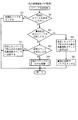
図4は、パチンコ機Pの電源入時に主制御基板Cで実行される立ち上げ処理のフローチャートである。この処理では、バックアップが有効であれば、バックアップエリア13eに記憶された各データを元の状態に戻し、遊技の制御を電源が断される前の状態から続行する。一方、バックアップが有効でなかったり、或いは、バックアップが有効であっても電源入時にクリアスイッチ23が押下された場合には、初期化処理を実行する。
【0046】
まず、割込を禁止し(S5)、次に、本来のスタック領域にスタックされているデータを壊さないために、仮のスタックポインタを設定する(S6)。クリアスイッチ23がオンされているか否かを確認し(S7)、オンされていれば(S7:Yes)、処理をS9へ移行して初期化処理を実行する。クリアスイッチ23がオンされていなければ(S7:No)、バックアップが有効であるか否かを確認する(S8)。この確認は、RAM13の所定のエリアに書き込まれたキーワードが正しく記憶されているか否かにより判断する。キーワードが正しく記憶されていればバックアップは有効であり、逆に、キーワードが正しくなければバックアップデータは破壊されているので、そのバックアップは有効ではない。バックアップが有効であれば(S8:Yes)、処理をS14へ移行して、主制御基板Cの各状態を電源の断前の状態に復帰させる。一方、バックアップが有効でなければ(S8:No)、処理をS9へ移行して初期化処理を実行する。
【0047】
S9の処理からの初期化処理では、まず、正規のスタックポインタを設定し、スタックの内容を整えた後(S9)、RAMクリア及び初期化処理を実行して(S10)、RAM13及びI/O等の各値を初期化する。その後、割込を許可し(S11)、その割込を使って初期化コマンドを払出制御基板Hへ送信して(S12)、主制御基板Cで初期化処理が実行されたことを払出制御基板Hへ報せる。払出制御基板Hは、主制御基板Cに比べて処理が軽いので、主制御基板Cより先に立ち上げ処理が終了する。よって、払出制御基板Hは、主制御基板Cから送信される初期化コマンドを確実に受信することができる。主制御基板Cは、初期化コマンドの送信後、その初期化コマンドを受信した払出制御基板Hが初期化処理を完了するために充分な時間をウエイトするためにウエイト処理を実行して(S13)、次の処理への移行を所定時間待機する。ウエイト処理の実行後は、払出制御基板Hも確実に立ち上がっているので、処理をS18へ移行して、遊技の制御を開始する。
【0048】
S14からの復帰処理では、まず、バックアップエリア13eへ退避した各レジスタやI/O等のデータをそのバックアップエリア13eから読み出して、これら各データを元のレジスタやI/O等へ書き込む(S14)。更に、バックアップエリア13eからスタックポインタの値を読み出して、これをスタックポインタへ書き込み、電源断前(停電前)の状態に戻す(S15)。その後、割込を許可し(S16)、残賞球数カウンタ13cの値を賞球払出許可コマンドの2バイト目のデータとしてセットし、許可した割込を使って、その賞球払出許可コマンドを払出制御基板Hへ送信する(S17)。払出制御基板Hは、この賞球払出許可コマンドを受信することにより、賞球の払い出しが可能になる。その後は、処理をS18へ移行し、このS18の処理の後に実行される各処理(S19)によって、電源断により中断されていた遊技の制御を、電源断前の状態から続行する。
【0049】
S18の処理では、停電フラグ13dがオンされているか否かを確認し(S18)、オンされていなければ(S18:No)、未だ停電は発生していないので、主制御基板Cのメイン処理となる各処理を実行して(S19)、パチンコ機Pの遊技の制御を行う。図5に示す賞球処理をはじめ、パチンコ機Pの遊技の各制御は、この各処理(S19)の中で実行される。
【0050】
S18の処理において、停電フラグ13dがオンされていれば(S18:Yes)、既に停電の発生等により電源が断されたということである。よって、かかる場合には、まず、割込を禁止して(S20)、各割込処理の進行をストップする。次に、停電解消後の復帰処理(S14,S15)に備えて、停電フラグ13dをオフし(S21)、更に、スタックポインタの値をバックアップエリア13eへ書き込み(S22)、各レジスタおよびI/O等の値をバックアップエリア13eへ書き込んで(S23)、停電の発生等による電源断時の状態を記憶する。更に、その他停電処理を実行し(S24)、その後は、制御系の駆動電圧がダウンして処理が実行できなくなるまで、処理をループする。
【0051】
このように停電の発生等による電源断時には、その電源断を割込の禁止設定をすることができないノンマスカブル割込(図3)で即座に認識し、そのノンマスカブル割込で停電の発生を報せる停電フラグ13dのオンのみをする。そして、停電時処理(S20〜S24)は、停電フラグ13dがオンされている場合に、メイン処理(図4)において実行するように構成している。よって、パチンコ機Pの遊技の制御を行う各処理(S19)の実行途中で、かかる停電時処理を実行することがない。即ち、停電時処理を、他の制御に支障を来すことのない好適なタイミングで実行することができるのである。これにより、制御プログラムの簡略化と小容量化とを実現することができる。
【0052】
図5は、主制御基板Cの各処理(図4のS19)の中で実行される賞球処理のフローチャートである。賞球処理は、普通入賞口2や第1種始動口4或いは大入賞口5へ入賞した球を検出する入賞検出処理と(S30)、賞球コマンドを払出制御基板Hへ送信する賞球コマンド送信処理と(S40)、払出制御基板Hによって払い出された賞球を検出する賞球検出処理(S50)との3つの処理によって構成されている。
【0053】
入賞検出処理(S30)では、まず、いずれかの普通入賞スイッチ17又は第1種始動口スイッチ18により、球が検出された否かを確認する(S31)。いずれかのスイッチ17,18によって球が検出された場合には(S31:Yes)、6個の賞球を払い出すために、賞球ポインタ13bの値番目の賞球バッファ13aへ「6」を書き込み(S32)、賞球ポインタ13bの値を「1」加算する(S33)。一方、いずれのスイッチ17,18によっても球が検出されない場合には(S31:No)、S32およびS33の処理をスキップして、S34の処理へ移行する。
【0054】
S34の処理では、Vカウントスイッチ19又は10カウントスイッチ20により球が検出された否かを確認する(S34)。いずれかのスイッチ19,20によって球が検出された場合には(S34:Yes)、15個の賞球を払い出すために、賞球ポインタ13bの値番目の賞球バッファ13aへ「15」を書き込み(S35)、賞球ポインタ13bの値を「1」加算する(S36)。一方、いずれのスイッチ19,20によっても球が検出されない場合には(S34:No)、S35およびS36の処理をスキップして、入賞検出処理(S30)を終了し、S40の賞球コマンド送信処理へ移行する。
【0055】
賞球コマンド送信処理(S40)では、まず、賞球ポインタ13bの値が「0」であるか否かを調べる(S41)。賞球ポインタ13bの値が「0」でなければ(S41:No)、払い出すべき賞球数のデータが賞球バッファ13aに記憶されているということなので、0番目の賞球バッファ13aの値を賞球コマンドの2バイト目のデータとしてセットし、その賞球コマンドを払出制御基板Hへ送信する(S42)。賞球コマンドの送信後は、その賞球コマンドによって送信した賞球数データである、0番目の賞球バッファ13aの値を残賞球数カウンタ13cへ加算する(S43)。そして、1番目以降の賞球バッファ13aの値を小さいアドレス側へ順に1バイトずつシフトして(S44)、賞球バッファ13aの値を更新すると共に、送信した0番目の賞球バッファ13aの値を消去し、更に、賞球ポインタ13bの値を「1」減算する(S45)。一方、S41の処理において、賞球ポインタ13bの値が「0」であれば(S41:Yes)、払い出すべき賞球数のデータは賞球バッファ13aに記憶されていないので、S42〜S45の各処理をスキップして、賞球コマンド送信処理(S40)を終了し、S50の賞球検出処理へ移行する。
【0056】
賞球検出処理(S50)では、まず、賞球カウントスイッチ22がオンされたか否かを判断する(S51)。賞球カウントスイッチ22のオンが検出された場合には(S51:Yes)、賞球が1個払い出されたということなので、残賞球数カウンタ13cの値を確認し(S52)、その値が「0」でなければ(S52:No)、払い出された賞球に対応して残賞球数カウンタ13cの値を「1」減算する(S53)。一方、賞球カウントスイッチ22のオンが検出されない場合には(S51:No)、賞球は払い出されていないので、また、賞球カウントスイッチ22のオンが検出されても残賞球数カウンタ13cの値が「0」であれば(S51:Yes,S52:Yes)、残賞球数カウンタ13cの値を減算することはできないので、S53の処理をスキップして、賞球検出処理(S50)を終了する。これにより、図5の賞球処理が終了する。
【0057】
次に、図6から図8を参照して、払出制御基板Hで行われる各処理について説明する。図6は、払出制御基板Hの割込処理で実行されるコマンド受信処理のフローチャートである。主制御基板Cから送信されたコマンドを払出制御基板Hが受信すると、その度に割り込みが発生し、このコマンド受信処理が実行される。なお、このコマンド受信処理を実行する割込は、割込の禁止設定ができないノンマスカブル割込ではなく、割込の禁止設定が可能な割込である。
【0058】
コマンド受信処理では、まず、受信したコマンドが初期化コマンドであるか否かを判断する(S61)。そのコマンドが初期化コマンドであれば(S61:Yes)、その初期化コマンドの受信を記憶するべく、初期化フラグ33bをオンして(S62)、このコマンド受信処理を終了する。一方、受信したコマンドが初期化コマンドでなければ(S61:No)、そのコマンドが賞球払出許可コマンドであるか否かを判断する(S63)。受信したコマンドが賞球払出許可コマンドであれば(S63:Yes)、その賞球払出許可コマンドの2バイト目のデータとして指示される値を残賞球数カウンタ33aへ書き込み(S64)、残賞球数カウンタ33aの値を主制御基板Cの残賞球数カウンタ13cの値と一致させる。更に、この賞球払出許可コマンドの受信を記憶するべく、賞球払出許可フラグ33cをオンして(S65)、このコマンド受信処理を終了する。
【0059】
受信したコマンドが、初期化コマンドでも賞球払出許可コマンドでもなければ(S61:No,S63:No)、そのコマンドが賞球コマンドであるか否かを判断する(S66)。受信したコマンドが賞球コマンドであれば(S66:Yes)、その賞球コマンドの2バイト目のデータとして指示される賞球数を残賞球数カウンタ33aへ加算し(S67)、このコマンド受信処理を終了する。一方、受信したコマンドが賞球コマンドでもない場合には(S66:No)、受信したコマンドに応じた処理を実行して(S68)、このコマンド受信処理を終了する。
【0060】
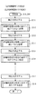
図7は、パチンコ機Pの電源入時に払出制御基板Hで実行される立ち上げ処理のフローチャートである。この処理では、バックアップが有効であれば、バックアップエリア33eに記憶された各データを元の状態に戻し、賞球の払出制御を電源が断される前の状態から続行する。一方、バックアップが有効でなかったり、或いは、バックアップが有効であっても電源入時にクリアスイッチ23が押下された場合には、初期化処理を実行する。
【0061】
まず、割込を禁止し(S71)、次に、本来のスタック領域にスタックされているデータを壊さないために、仮のスタックポインタを設定する(S72)。クリアスイッチ23がオンされているか否かを確認し(S73)、オンされていれば(S73:Yes)、処理をS75へ移行して初期化処理を実行する。クリアスイッチ23がオンされていなければ(S73:No)、バックアップが有効であるか否かを確認する(S74)。この確認は、RAM33の所定のエリアに書き込まれたキーワードが正しく記憶されているか否かにより判断する。キーワードが正しく記憶されていればバックアップは有効であり、逆に、キーワードが正しくなければバックアップデータは破壊されているので、そのバックアップは有効ではない。バックアップが有効であれば(S74:Yes)、処理をS82へ移行して、主制御基板Cの各状態を電源の断前の状態に復帰させる。一方、バックアップが有効でなければ(S74:No)、処理をS75へ移行して初期化処理を実行する。
【0062】
S75の処理からの初期化処理では、まず、正規のスタックポインタを設定し、スタックの内容を整えた後(S75)、RAMクリア及び初期化処理を実行して(S76)、RAM33及びI/O等の各値を初期化する。その後、割込を許可して(S77)、前述した図6のコマンド受信処理を実行可能とする。割込の許可後は、主制御基板Cからの賞球の払出許可をウエイトするべく、初期化フラグ33b又は賞球払出許可フラグ33cのいずれかがオンされるまで処理をループする(S78:No,S79:No)。初期化フラグ33b又は賞球払出許可フラグ33cのいずれかがオンされれば(S78:Yes又はS79:Yes)、主制御基板Cから賞球の払出許可が出されたということである。よって、かかる場合には、次の電源断に備えて、初期化フラグ33b及び賞球払出許可フラグ33cを共にオフした後(S80)、処理をS88へ移行する。
【0063】
S82からの復帰処理では、まず、バックアップエリア33eへ退避した各レジスタやI/O等のデータをそのバックアップエリア33eから読み出して、これら各データを元のレジスタやI/O等へ書き込む(S82)。更に、バックアップエリア33eからスタックポインタの値を読み出して、これをスタックポインタへ書き込み、電源断前(停電前)の状態に戻す(S83)。その後、割込を許可して(S84)、図6のコマンド受信処理を実行可能とする。割込の許可後は、主制御基板Cからの賞球の払出許可をウエイトするべく、初期化フラグ33b又は賞球払出許可フラグ33cのいずれかがオンされるまで処理をループする(S85:No,S86:No)。
【0064】
賞球払出許可フラグ33cがオンされれば(S85:Yes)、主制御基板Cから賞球の払出許可が出されたということである。よって、かかる場合には、次の電源断に備えて、賞球払出許可フラグ33cをオフした後(S80)、処理をS88へ移行する。このS88の処理の後に実行される各処理(S89)によって、電源断により中断されていた制御を電源断前の状態から続行する。これにより、賞球の払い出しが可能となる。
【0065】
一方、初期化フラグ33bがオンされれば(S85:No,S86:Yes)、主制御基板Cから初期化コマンドが送信されたということである。よって、かかる場合には、RAMクリア及び初期化処理を実行して(S87)、払出制御基板Hを初期化した後、処理をS88へ移行する。図8の賞球払出処理は、このS88の処理の後の各処理(S89)の中で実行されるので、払出制御基板Hによる賞球の払い出しは、初期化フラグ33bがオンされるまで待機されることになる。
【0066】
なお、図4で説明した通り、主制御基板Cは初期化コマンドの送信後、ウエイト処理(S13)を実行しその後の処理の実行を所定時間待機するので、払出制御基板HによるRAMクリア及び初期化処理(S87)の実行中に、主制御基板Cから新たなコマンドが送信されることはない。よって、払出制御基板Hは、かかる場合にも遊技の払出制御を正常に行うことができるのである。
【0067】
S88の処理では、停電フラグ33dがオンされているか否かを確認し(S88)、オンされていなければ(S88:No)、未だ停電は発生していないので、払出制御基板Hのメイン処理となる各処理を実行して(S89)、賞球又は貸し球の払出制御を行う。後述する図8の賞球払出処理をはじめ、払出制御基板Hの各制御は、割込処理を除いて、この各処理(S89)の中で実行される。
【0068】
S88の処理において、停電フラグ33dがオンされていれば(S88:Yes)、既に停電の発生等により電源が断されたということである。よって、かかる場合には、まず、割込を禁止して(S90)、各割込処理の進行をストップする。この割込の禁止により、図6のコマンド受信処理の新たな実行も禁止される。次に、停電解消後の復帰処理(S82,S83)に備えて、停電フラグ33dをオフし(S91)、更に、スタックポインタの値をバックアップエリア33eへ書き込み(S92)、各レジスタおよびI/O等の値をバックアップエリア33eへ書き込んで(S93)、停電の発生等による電源断時の状態を記憶する。更に、その他停電処理を実行し(S94)、その後は、制御系の駆動電圧がダウンして処理が実行できなくなるまで、処理をループする。
【0069】
このように停電の発生等による電源断時には、その電源断を割込の禁止設定をすることができないノンマスカブル割込(図3)で即座に認識し、そのノンマスカブル割込で停電の発生を報せる停電フラグ33dのオンのみをする。そして、停電時処理(S90〜S94)は、停電フラグ33dがオンされている場合に、メイン処理(図7)において実行するように構成している。よって、賞球や貸し球の払出制御を行う各処理(S89)の実行途中で、かかる停電時処理を実行することがない。即ち、停電時処理を、他の制御に支障を来すことのない好適なタイミングで実行することができるので、制御プログラムの簡略化と小容量化とを実現することができるのである。
【0070】
図8は、払出制御基板Hの各処理(S89)の中で実行される賞球払出処理のフローチャートである。この賞球払出処理により、賞球の払い出しと、払い出された賞球の検出とが行われる。賞球払出処理では、まず、残賞球数カウンタ33aの値を調べ(S101)、その値が「0」でなければ(S101:No)、未払いの賞球が残っているので、賞球払出用モータ21を駆動して賞球を1個払い出す(S102)。一方、残賞球数カウンタ33aの値が「0」であれば(S101:Yes)、未払いの賞球は残っていないので、S102の賞球の払い出し処理をスキップする。
【0071】
S103の処理において、賞球カウントスイッチ22でオンが検出されれば(S103:Yes)、賞球の払い出しが行われたということである。よって、かかる場合には、残賞球数カウンタ33aの値を確認し(S104)、その値が「0」でなければ(S104:No)、払い出された賞球に対応して残賞球数カウンタ33aの値を「1」減算し(S105)、この賞球払出処理を終了する。一方、賞球カウントスイッチ22のオンが検出されない場合や(S103:No)、賞球カウントスイッチ22のオンが検出されても(S103:Yes)、残賞球数カウンタ33aの値が「0」であれば(S104:Yes)、S105の処理をスキップして、この賞球払出処理を終了する。
【0072】
以上説明したように、本実施例のパチンコ機Pによれば、停電の発生等による電源断時には、その電源断を割込の禁止設定をすることができないノンマスカブル割込(図3)で即座に認識し、そのノンマスカブル割込で停電の発生を報せる停電フラグ13d,33dのオンのみをする。そして、停電時処理(図4のS20〜S24,図7のS90〜S94)は、停電フラグ13d,33dがオンされている場合に、メイン処理(図4,図7)において実行するように構成している。よって、各処理(S19,S89)の実行途中で、かかる停電時処理を実行することがない。即ち、停電時処理を、他の制御に支障を来すことのない好適なタイミングで実行することができるので、制御プログラムの簡略化と小容量化とを実現することができるのである。
【0073】
なお、図4及び図7における停電時処理(S20〜S24,S90〜S94)を、好適なタイミングを見計らって、それぞれ各処理(S19,S89)の中で実行するようにしても良い。
【0074】
次に、図9から図12を参照して、第2実施例について説明する。前記した第1実施例では、停電監視回路50から出力される停電信号51を、各MPU11,31のNMI割込端子にそれぞれ入力し、NMI割込処理(図3)によって、停電フラグ13d,33dをオンし、その停電フラグ13d,33dがオンされている場合に、メイン処理の好適なタイミングで、停電時における各データの退避処理である停電時処理(S20〜S24,S90〜S94)を実行するようにしていた。
【0075】
これに対し、第2実施例では、NMI割込を使用せず、停電監視回路50から出力される停電信号51を、各MPU11,31の外部割込端子(INT割込端子)にそれぞれ入力し、割込の禁止設定が可能なINT割込処理(図9)によって、停電時における各データの退避処理である停電時処理(S201〜S204)を実行するようにしている。INT割込は、NMI割込と異なり、割込の禁止設定が可能であるので、停電時処理の実行に不適な場合には割込を禁止することにより、その停電時処理の実行を規制することができる。よって、停電時処理を、他の制御に支障を来すことのない好適なタイミングで実行することができるので、制御プログラムの簡略化と小容量化とを実現することができる。
【0076】
なお、停電監視回路50から出力される停電信号51がオンオフを繰り返してふらつくと、NMI割込の場合には、割込の禁止設定ができないので、そのNMI割込が多重に発生して、スタックオーバーが発生するなど制御に支障を来すことがある。しかし、INT割込の場合には、割込の禁止設定ができるので、多重割込の発生を防止することができる。よって、INT割込の場合には、多重割込の対策プログラムを必要とせず、その分、制御プログラムの簡略化と小容量化とを図ることができる。
【0077】
第2実施例の説明にあたり、前記した第1実施例と同一の部分には同一の符号を付してその説明を省略する。
【0078】
図9は、停電の発生等によるパチンコ機Pの電源断時に、主制御基板C及び払出制御基板Hで、それぞれ別々に実行されるINT割込処理のフローチャートである。このINT割込処理により、停電の発生等による電源断時の主制御基板C及び払出制御基板Hの状態がそれぞれのバックアップエリア13e,33eに記憶される。なお、INT割込処理は、主制御基板CのROM12と払出制御基板HのROM32とに、それぞれ別々に搭載される処理であるが、フローチャートの表記上、同様に表すことができるので、図9にまとめて図示している。
【0079】
停電の発生等によりパチンコ機Pの電源が断されると、停電監視回路50から停電信号51が主制御基板C及び払出制御基板Hの各MPU11,31のINT割込端子へそれぞれ出力される。各MPU11,31は、INT割込端子に停電信号51が入力されると、割込が許可されていれば即座に、割込が禁止されていれば許可されるタイミングで、それぞれ実行中の制御を中断して、INT割込処理を開始する。停電信号51が出力された後所定時間は、主制御基板C及び払出制御基板Hの処理が実行できるように、図示しない電源回路から電力供給されており、この所定時間内に、INT割込処理が実行される。
【0080】
INT割込処理では、まず、多重割込の発生を防止するべく、割込を禁止し(S201)、次に、スタックポインタの値をバックアップエリア13e,33eへ書き込み(S202)、更に、各レジスタおよびI/O等の値をバックアップエリア13e,33eへ書き込んで(S203)、停電の発生等による電源断時の状態を記憶する。その後、主制御基板C及び払出制御基板Hに応じてそれぞれ異なるその他停電処理を実行し(S204)、その後は、電源が完全に断して処理が実行できなくなるまで、処理をループする。なお、INT割込の発生により割込が自動的に禁止されるMPUを用いる場合には、S201の割込禁止処理を省略する。
【0081】
図10は、パチンコ機Pの電源入時に主制御基板Cで実行される第2実施例の立ち上げ処理のフローチャートであり、また、図11は、パチンコ機Pの電源入時に払出制御基板Hで実行される第2実施例の立ち上げ処理のフローチャートである。これらの処理では、バックアップが有効であれば、バックアップエリア13e,33eに記憶された各データを元の状態に戻し、制御を電源が断される前の状態から続行する。一方、バックアップが有効でなかったり、或いは、バックアップが有効であっても電源入時にクリアスイッチ23が押下された場合には、初期化処理を実行する。制御内容は、前記した第1実施例と同様であるので、その説明は省略する。なお、図10の主制御基板Cの処理では、S13及びS17の処理の終了後に、主制御基板Cのメイン処理となる各処理(S19)が実行され、図11の払出制御基板Hの処理では、S80及びS87の処理の終了後に、払出制御基板Hのメイン処理となる各処理(S89)が実行される。
【0082】
図12は、主制御基板C及び払出制御基板Hのメイン処理で、それぞれ別々に実行される各処理(S19,S89)のフローチャートである。なお、この各処理(S19,S89)は、主制御基板CのROM12と払出制御基板HのROM32とに、それぞれ別々に搭載されているが、図9の場合と同様に、フローチャートの表記上、同様に表すことができるので、図12にまとめて図示している。
【0083】
各処理(S19,S89)では、まず、割込を禁止し(S211)、S201〜S204の停電時処理を処理の途中で実行できない処理を実行する(S212)。その後、割込を許可し(S213)、かかる停電時処理を処理の途中で実行できる処理を実行する(S214)。更に、割込を禁止し(S215)、停電時処理を処理の途中で実行できない処理を実行する(S216)。・・・その後、割込を許可し(S217)、停電時処理を処理の途中で実行できる処理を実行する(S218)。
【0084】
このように各処理(S19,S89)では、S201〜S204の停電時処理を、処理の途中で実行できない処理を実行する場合には、前もって割込を禁止し、一方、かかる停電時処理を処理の途中で実行できる処理を実行する場合には、前もって割込を許可している。これにより、停電時処理の実行に好適なタイミングでのみ、その停電時処理を実行し、逆に、停電時処理の実行に都合の悪いタイミングでは、その停電時処理の実行を規制することができるので、制御プログラムを簡略化された小容量のプログラムとすることができるのである。
【0085】
なお、上記実施例において、請求項1記載の停電時処理としては、図3のS2の処理が該当し、主遊技処理としては、図4のS18及びS19の繰り返し行われる処理または図10のS19の処理が該当し、停電発生時処理としては、図4のS22及びS23の処理または図9のS202及びS203の処理が該当し、復帰処理としては、図4及び図10のS14〜S17の処理が該当し、主立上げ時処理としては、図4及び図10のS5〜S17の処理が該当し、立上げ時コマンド送信処理としては、図4及び図10のS12及びS17の処理が該当し、副遊技処理としては、図7のS88及びS89の繰り返し行われる処理または図11のS89の処理が該当し、副立上げ時処理としては、図7及び図11のS71〜S87の処理が該当し、待機処理としては、図7及び図11のS78とS79の処理がNoとなった場合およびS85とS86の処理がNoとなった場合が該当する。
【0086】
【0087】
以上、実施例に基づき本発明を説明したが、本発明は上記実施例に何ら限定されるものではなく、本発明の趣旨を逸脱しない範囲内で種々の改良変形が可能であることは容易に推察できるものである。
【0088】
例えば、上記各実施例では、RAM13,33は、いずれも不揮発性のメモリであるスタティックRAMにより構成され、電源の断時には、これらのRAM13,33に、バックアップ用の充電池13x,33xによってバックアップ電圧を供給し、RAM13,33の各内容を保持(バックアップ)するように構成した。しかし、これに代えて、RAM13,33をEEPROMやフラッシュメモリなどのバックアップ電圧を加えなくても内容を保持できるメモリによって構成し、バックアップ用の充電池13x,33xを除くようにしても良い。また、第1実施例のNMI割込処理を、割込の禁止設定が可能な他の割込処理(例えば、INT割込処理)により実行するようにしても良い。
【0089】
本発明を上記実施例とは異なるタイプのパチンコ機等に実施しても良い。例えば、一度大当たりすると、それを含めて複数回(例えば2回、3回)大当たり状態が発生するまで、大当たり期待値が高められるようなパチンコ機(通称、2回権利物、3回権利物と称される)として実施しても良い。また、大当たり図柄が表示された後に、所定の領域に球を入賞させることを必要条件として特別遊技状態となるパチンコ機として実施しても良い。更に、パチンコ機以外にも、アレパチ、雀球、スロットマシン、いわゆるパチンコ機とスロットマシンとが融合した遊技機などの各種遊技機として実施するようにしても良い。
【0090】
なお、スロットマシンは、例えばコインを投入して図柄有効ラインを決定させた状態で操作レバーを操作することにより図柄が変動され、ストップボタンを操作することにより図柄が停止されて確定される周知のものである。従って、スロットマシンの基本概念としては、「複数の識別情報からなる識別情報列を変動表示した後に識別情報を確定表示する可変表示手段を備え、始動用操作手段(例えば操作レバー)の操作に起因して識別情報の変動が開始され、停止用操作手段(例えばストップボタン)の操作に起因して、或いは、所定時間経過することにより、識別情報の変動が停止され、その停止時の確定識別情報が特定識別情報であることを必要条件として、遊技者に有利な特別遊技状態を発生させる特別遊技状態発生手段とを備えたスロットマシン」となり、この場合、遊技媒体はコイン、メダル等が代表例として挙げられる。
【0091】
また、パチンコ機とスロットマシンとが融合した遊技機の具体例としては、複数の図柄からなる図柄列を変動表示した後に図柄を確定表示する可変表示手段を備えており、球打出用のハンドルを備えていないものが挙げられる。この場合、所定の操作(ボタン操作)に基づく所定量の球の投入の後、例えば操作レバーの操作に起因して図柄の変動が開始され、例えばストップボタンの操作に起因して、或いは、所定時間経過することにより、図柄の変動が停止され、その停止時の確定図柄がいわゆる大当たり図柄であることを必要条件として遊技者に有利な大当たり状態が発生させられ、遊技者には、下部の受皿に多量の球が払い出されるものである。
【0092】
以下に本発明の変形例を示す。請求項1記載の遊技機において、前記実行タイミング規制手段は、前記停電監視手段から停電信号が出力された場合に発生する割込であって、割込の禁止設定が不可能なノンマスカブル割込と、そのノンマスカブル割込の実行により停電の発生を指示する停電発生指示手段とを備えており、その停電発生指示手段により停電の発生が指示された場合に、前記ノンマスカブル割込以外の他の処理によって前記停電時退避手段を実行させるものであることを特徴とする遊技機1。停電の発生時には、割込の禁止設定が不可能なノンマスカブル割込によって停電の発生のみを記憶し、その停電の発生が記憶されている場合に、ノンマスカブル割込以外の他の処理によって、停電時退避手段が実行される。よって、ノンマスカブル割込により停電の発生を即座に認識できると共に、停電時の退避処理を制御上の都合の良いタイミングで実行することができる。なお、停電発生指示手段としては、ノンマスカブル割込処理の中でオンされる停電フラグなどが例示される。
【0093】
遊技機1において、前記停電発生指示手段により停電の発生が指示された場合に、前記停電時退避手段を少なくとも実行可能な状態にした後(前記停電時退避手段の実行中又は実行後を含む)、その停電発生指示手段の停電の発生の指示を解除する停電指示解除手段と、その停電指示解除手段の実行後に前記ノンマスカブル割込が実行された場合に前記停電発生指示手段による停電の発生の指示を禁止する停電指示禁止手段とを備えていることを特徴とする遊技機2。停電解消時における停電時復帰手段を、停電発生指示手段による停電の発生の指示を解除した状態で実行することができるので、復帰後の処理を正常に実行することができるのである。
【0094】
遊技機1又は2において、前記停電時退避手段を実行する他の処理は、メイン処理または割込の禁止設定が可能な割込処理であることを特徴とする遊技機3。よって、停電時退避手段の実行に都合の悪いタイミングにおいては、その実行を禁止することができるので(待機させることができるので)、簡略化された小容量のプログラムとすることができる。
【0095】
請求項1記載の遊技機において、前記停電時退避手段は、前記停電監視手段から停電信号が出力された場合に発生する割込であって、割込の禁止設定が可能な割込により実行されるものであり、前記実行タイミング規制手段は、前記停電時退避手段の実行に不適なタイミングにおいては前記割込を禁止する一方、前記停電時退避手段の実行に好適なタイミングにおいては前記割込を許可するものであることを特徴とする遊技機4。よって、停電時の退避処理を制御上の都合の良いタイミングで実行することができる。
【0096】
請求項1記載の遊技機又は遊技機1から4のいずれかに記載の遊技機において、前記停電監視手段による停電信号の出力から、前記実行タイミング規制手段により前記停電時退避手段の実行が最も遅らされた場合における前記停電時退避手段の実行に充分な時間、制御系の駆動電圧を有効な状態に維持する電源手段を備えていることを特徴とする遊技機5。停電時退避手段の実行が最も遅れた場合においても、電源手段により、制御系の駆動電圧はその停電時退避手段の実行に充分な時間有効な状態に維持される。よって、停電時の退避処理を制御上の都合の良いタイミングの到来を待って実行することができる。
【0097】
請求項1記載の遊技機又は遊技機1から5のいずれかに記載の遊技機において、前記停電時退避手段は、スタックポインタ、レジスタ或いはI/Oの値を前記バックアップ記憶手段へ退避するものであることを特徴とする遊技機6。
【0098】
請求項1記載の遊技機又は遊技機1から6のいずれかに記載の遊技機において、遊技の制御を行う主制御基板と、その主制御基板から送信される制御コマンドに基づいて有価物体の払出制御を行う払出制御基板とを備えており、前記バックアップ記憶手段と、前記停電時退避手段と、前記停電時復帰手段と、前記実行タイミング規制手段とは、前記主制御基板および払出制御基板にそれぞれ設けられていることを特徴とする遊技機7。停電の発生時に主制御基板および払出制御基板の遊技状態をバックアップして、これを停電の解消後に復帰することができるので、停電等の発生により電源が断されても、払出制御基板により有価物体を確実に払い出すことができる。
【0099】
遊技機7において、前記主制御基板と払出制御基板との送受信は、前記主制御基板から払出制御基板への一方向に行われることを特徴とする遊技機8。
【0100】
請求項1記載の遊技機または遊技機1から8のいずれかにおいて、前記遊技機はパチンコ機であることを特徴とする遊技機9。中でも、パチンコ機の基本構成としては操作ハンドルを備え、その操作ハンドルの操作に応じて球を所定の遊技領域へ発射し、球が遊技領域内の所定の位置に配設された作動口に入賞(又は作動口を通過)することを必要条件として、表示装置において変動表示されている識別情報が所定時間後に確定停止されるものが挙げられる。また、特別遊技状態の発生時には、遊技領域内の所定の位置に配設された可変入賞装置(特定入賞口)が所定の態様で開放されて球を入賞可能とし、その入賞個数に応じた有価価値(景品球のみならず、磁気カードへ書き込まれるデータ等も含む)が付与されるものが挙げられる。
【0101】
請求項1記載の遊技機または遊技機1から8のいずれかにおいて、前記遊技機はスロットマシンであることを特徴とする遊技機10。中でも、スロットマシンの基本構成としては、「複数の識別情報からなる識別情報列を変動表示した後に識別情報を確定表示する可変表示手段を備え、始動用操作手段(例えば操作レバー)の操作に起因して、或いは、所定時間経過することにより、識別情報の変動が停止され、その停止時の確定識別情報が特定識別情報であることを必要条件として、遊技者に有利な特別遊技状態を発生させる特別遊技状態発生手段とを備えた遊技機」となる。この場合、遊技媒体はコイン、メダル等が代表例として挙げられる。
【0102】
請求項1記載の遊技機または遊技機1から8のいずれかにおいて、前記遊技機はパチンコ機とスロットマシンとを融合させたものであることを特徴とする遊技機11。中でも、融合させた遊技機の基本構成としては、「複数の識別情報からなる識別情報列を変動表示した後に識別情報を確定表示する可変表示手段を備え、始動用操作手段(例えば操作レバー)の操作に起因して識別情報の変動が開始され、停止用操作手段(例えばストップボタン)の操作に起因して、或いは、所定時間経過することにより、識別情報の変動が停止され、その停止時の確定識別情報が特定識別情報であることを必要条件として、遊技者に有利な特別遊技状態を発生させる特別遊技状態発生手段とを備え、遊技媒体として球を使用すると共に、前記識別情報の変動開始に際しては所定数の球を必要とし、特別遊技状態の発生に際しては多くの球が払い出されるように構成されている遊技機」となる。
【0103】
【発明の効果】
本発明の遊技機によれば、主制御手段は、電源が投入された場合に、立上げ時コマンド送信処理を含む主立上げ時処理を実行し、立上げ時コマンド送信処理の後に主遊技処理へと移行する。また、副制御手段は、電源が投入された場合に、待機処理を含む副立上げ時処理を実行し、待機処理の実行中に主制御手段から所定の制御コマンドが入力されると待機処理を終了して副遊技処理へと移行する。
よって、主制御手段は、主立上げ時処理内で所定の制御コマンドを出力した後に主遊技処理を実行し、副制御手段は、副立上げ時処理内で所定の制御コマンドを受信した後に副遊技処理を実行する。従って、主制御手段が主遊技処理へ移行するタイミングと副制御手段が副遊技処理へ移行するタイミングとを合わせることができるので、電源投入時にスムーズに制御を開始することができるという効果がある。
【図面の簡単な説明】
【図1】 本発明の一実施例であるパチンコ機の遊技盤の正面図である。
【図2】 パチンコ機の電気的構成を示したブロック図である。
【図3】 (a)は主制御基板で、(b)は払出制御基板で、それぞれ別々に実行されるNMI割込処理のフローチャートである。
【図4】 主制御基板で実行される立ち上げ処理のフローチャートである。
【図5】 主制御基板で実行される賞球処理のフローチャートである。
【図6】 払出制御基板の受信割込処理で実行されるコマンド受信処理のフローチャートである。
【図7】 払出制御基板で実行される立ち上げ処理のフローチャートである。
【図8】 払出制御基板で実行される賞球払出処理のフローチャートである。
【図9】 第2実施例の主制御基板及び払出制御基板でそれぞれ別々に実行されるINT割込処理のフローチャートである。
【図10】 第2実施例の主制御基板で実行される立ち上げ処理のフローチャートである。
【図11】 第2実施例の払出制御基板で実行される立ち上げ処理のフローチャートである。
【図12】 第2実施例の主制御基板及び払出制御基板のメイン処理でそれぞれ別々に実行される各処理のフローチャートである。
【符号の説明】
11 主制御基板のMPU(主制御手段の一部、演算部)
13 主制御基板のRAM(記憶部)
13d 停電フラグ
13e バックアップエリア
13x 主制御基板のバックアップ用の充電池
31 払出制御基板のMPU(副制御手段の一部)
33 払出制御基板のRAM
33d 停電フラグ
33e バックアップエリア
33x 払出制御基板のバックアップ用の充電池
50 停電監視回路(停電監視手段)
51 停電信号
C 主制御基板
H 払出制御基板
P パチンコ機(遊技機)[0001]
BACKGROUND OF THE INVENTION
The present invention relates to gaming machines represented by pachinko machines and slot machines.
[0002]
[Prior art]
For example, pachinko machine games are controlled mainly by the main control board. The main control board includes a payout control board that performs payout control of prize balls and rental balls, a sound effect control board that performs output control of sound effects, and a display control board that performs display control such as symbol variation display. It is connected. The control of each control board is performed by a command transmitted from the main control board to each control board in one direction.
[0003]
[0004]
[0005]
[Problems to be solved by the invention]
However,Since a command is transmitted in one direction from the main control board (main control means) to each control board (sub-control means),PowerThrowEnteredTheIn case,It is difficult to match the timing to shift to game processing by each control board including the main control board, and it is difficult to start control smoothly when the power is turned on.There was a problem.
[0006]
[0007]
The present invention has been made to solve the above-described problems,Synchronize the timing to shift to game processing by the main and sub control means, and start control smoothly when the power is turned onIt aims to provide a gaming machine that can.
[0008]
[Means for Solving the Problems]
In order to achieve this object, the gaming machine according to
[0009]
The gaming machine according to
[0010]
DETAILED DESCRIPTION OF THE INVENTION
Hereinafter, preferred embodiments of the present invention will be described with reference to the accompanying drawings. In this embodiment, a pachinko machine that is a kind of a ball game machine, in particular, a first type pachinko game machine will be described as an example of the game machine. Of course, the present invention can be used for other gaming machines such as a third-class pachinko gaming machine, a coin gaming machine, and a slot machine.
[0011]
FIG. 1 is a front view of a game board of a pachinko machine P according to the present embodiment. Around the
[0012]
Below the
[0013]
A V
[0014]
FIG. 2 is a block diagram showing the electrical configuration of the pachinko machine P, and in particular, a main control board C that controls the game contents of the pachinko machine P, and a payout control board that performs payout control of prize balls and rental balls. It is the block diagram which showed the electric constitution with H.
[0015]
The main control board C of the pachinko machine P includes an
[0016]
The winning ball buffer 13a is a buffer for storing the number of winning balls to be paid out when a ball that has been driven into the
[0017]
Here, the prize ball command is a command for instructing the payout control board H of the number of prize balls to be paid out, and is composed of 2 bytes. The first byte data of the prize ball command is data (for example, “A0H”) indicating that the command is a prize ball command, and the second byte data indicates the number of prize balls to be paid out. The data is shown. Since the maximum number of winning balls for one winning is 15 balls, 15 types of data “01H” to “0FH” corresponding to the maximum number of winning balls are used as the second byte data of the winning ball command. Yes.
[0018]
The prize ball command may be composed of 1 byte. As described above, since the maximum number of winning balls for one winning is 15 balls, when the winning ball command is composed of 1 byte, “01H” to “0FH” corresponding to the maximum winning ball number. Fifteen types of data are used as prize ball commands. In other words, when the upper 4 bits of a command composed of 1 byte are “0”, a winning ball command is set.
[0019]
The prize ball pointer 13b is a pointer indicating the position of the prize ball buffer 13a for storing the number of prize balls, and the number of prize balls to be paid out is stored in the value-th prize ball buffer 13a of the prize ball pointer 13b. The value of the prize ball pointer 13b is incremented by "1" by writing the number of prize balls in the prize ball buffer 13a, and conversely, the value of the 0th prize ball buffer 13a is transmitted to the payout control board H. “1” is subtracted.
[0020]
The remaining prize ball number counter 13c is a counter for storing the number of unpaid prize balls, and is a counter for managing the number of prize balls to be paid out by the payout control board H on the main control board C. Each time the main control board C instructs the payout control board H to pay out the prize ball, the value of the remaining prize ball counter 13c is incremented, and conversely, the payout control board H pays out the prize ball. Each time the award ball count
[0021]
Here, the winning ball payout permission command is a command transmitted from the main control board C to the payout control board H at the end of the startup process of the main control board C when the backup is valid. This prize ball payout permission command instructs the payout control board H after the start-up process to be permitted to pay out prize balls. The prize ball payout permission command is composed of 2 bytes. The first byte data is data (for example, “A1H”) indicating that the command is a prize ball payout permission command, and the second byte data is data indicating the number of unpaid prize balls. It is said that. Specifically, the value of the remaining winning ball number counter 13c is set as the second byte data.
[0022]
When the payout control board H receives the prize ball payout permission command, it reads out the second byte of data, writes it into the remaining prize
[0023]
The prize ball payout permission command may be composed of 1 byte as in the case of the prize ball command. In this case, the value of the remaining prize ball counter 13c of the main control board C is not set as the value of the prize ball payout permission command. Therefore, in the start-up process after backup, the main control board C and the payout control board H The remaining ball counters 13c and 33a cannot be matched. Further, the main control board C is configured to transmit a command indicating the state of the pachinko machine P to the payout control board H after the start-up process is completed, instead of the prize ball payout permission command. Then, it may be configured to wait for the payout of the winning ball until a command transmitted from the main control board C is received. The state of the pachinko machine P is not necessarily the same before the power is turned off and after the power is turned on. Despite the fact that prize balls can be paid out before the power is turned off, after the power is turned on again, for example, there are not enough tank balls to store the prize balls to be paid out. In that case, the prize ball cannot be paid out. Therefore, after starting up the main control board C, a command indicating the state of the pachinko machine P is transmitted to the payout control board H, and the payout control board H pays out the winning ball only after receiving the command. It is configured not to be able to. Some commands indicating the state of the pachinko machine P stop the payout of the prize ball, so if the state of the pachinko machine P after the power is turned on cannot pay out the prize ball, A command for stopping the payout of the prize ball is transmitted, and the payout of the prize ball by the payout control board H is further waited.
[0024]
The power failure flag 13d is a flag for reporting a power failure due to the occurrence of a power failure or the like. When a power failure or the like occurs and the power is cut off, a power failure signal 51 is output from a power
[0025]
In the backup area 13e, when the power is cut off due to the occurrence of a power failure or the like, the power of the pachinko machine P is restored to the state before the power is turned off when the power is turned on again. This is an area for storing stack pointers, values of registers, I / O, and the like. The writing to the backup area 13e is executed in the power failure process when the power failure flag 13d is on (when the power is cut off) (see S22 to S24 in FIG. 4), and each value written to the backup area 13e is reversed. Is performed in the initialization process at the time of power-on (including power-on due to power failure cancellation, the same applies hereinafter) (see S14 and S15 in FIG. 4).
[0026]
The
[0027]
The
[0028]
The
[0029]
The prize
[0030]
The
[0031]
As described above, the main control board C is connected to the payout control board H via the buffers (inverter gates) 16 and 37 whose inputs and outputs are fixed. Therefore, transmission / reception of a prize ball command or the like between the main control board C and the payout control board H is performed only in one direction from the main control board C to the payout control board H, and the payout control board H to the main control board C. Can not be done. The main control board C and the payout control board H are connected by eight data lines and one strobe line, and when the data on the strobe line becomes active, the data is output onto the eight data lines. The transmitted data is transmitted from the main control board C to the payout control board H as a command.
[0032]
The payout control board H performs payout control of prize balls and lending balls, and is used as an
[0033]
The
[0034]
The remaining prize
[0035]
The
[0036]
The prize ball payout permission flag 33c is a flag that is turned on when the payout control board H receives a prize ball payout permission command transmitted from the main control board C, and is used to instruct permission for payout of prize balls. Flag. As described above, when receiving the prize ball payout permission command, the payout control board H turns on the prize ball payout permission flag 33c in order to store the prize ball payout permission (S65) and 2 bytes of the prize ball payout permission command. The eye data is written to the remaining winning
[0037]
Similarly to the power failure flag 13d of the main control board C described above, the
[0038]
As with the backup area 13e of the main control board C described above, when the power is cut off due to a power failure or the like, the backup area 33e returns the state of the pachinko machine P to the state before turning off the power when the power is turned on again. Therefore, it is an area for storing a stack pointer at the time of power-off (including when a power failure occurs, the same applies hereinafter), values of registers, I / O, and the like. The writing to the backup area 33e is executed in the power failure process when the
[0039]
The
[0040]
The power
[0041]
Next, each process performed in the main control board C and the payout control board H will be described with reference to the flowcharts shown in FIGS. 3A is executed by the main control board C when the power
[0042]
First, in the NMI interrupt process of FIG. 3A executed by the main control board C, when an NMI interrupt occurs, the process at power failure from S21 to S24 (including the loop after the process of S24) (see FIG. 4). Is checked (S1). If the process from S21 to S24 is not being executed (S1: No), the power failure flag 13d is turned on (S2). Conversely, if it is being executed (S1: Yes), the process of S2 is skipped, and this The NMI interrupt process is terminated. Note that the process being executed when an NMI interrupt occurs is checked by checking the address saved in the stack when the NMI interrupt occurs.
[0043]
Similarly, in the NMI interrupt process of FIG. 3B executed by the payout control board H, when an NMI interrupt occurs, the process at the time of power failure from S91 to S94 (including the loop after the process of S94) (see FIG. 7). ) Is being executed (S3). If the processing from S91 to S94 is not being executed (S3: No), the
[0044]
As described above, the power failure flags 13d and 33d are turned on only when the NMI interrupt processing is executed other than during the power failure processing (S21 to S24, S91 to S94). When the NMI interrupt processing is executed during the execution of the power failure, the power failure flags 13d and 33d are not turned on, so that the output of the power failure signal 51 from the power
[0045]
FIG. 4 is a flowchart of start-up processing executed on the main control board C when the pachinko machine P is turned on. In this process, if the backup is valid, each data stored in the backup area 13e is returned to the original state, and the game control is continued from the state before the power is turned off. On the other hand, if the backup is not valid, or if the
[0046]
First, interrupts are prohibited (S5), and then a temporary stack pointer is set so as not to destroy the data stacked in the original stack area (S6). It is confirmed whether or not the
[0047]
In the initialization process from the process of S9, first, a normal stack pointer is set, the contents of the stack are arranged (S9), RAM clearing and initialization process are executed (S10), and the
[0048]
In the return processing from S14, first, data such as each register and I / O saved in the backup area 13e is read from the backup area 13e, and these data are written to the original register and I / O (S14). . Further, the value of the stack pointer is read from the backup area 13e, written to the stack pointer, and returned to the state before the power is turned off (before the power failure) (S15). Thereafter, an interrupt is permitted (S16), the value of the remaining ball counter 13c is set as the second byte data of the winning ball payout permission command, and the winning ball payout permission command is set using the permitted interrupt. It transmits to the payout control board H (S17). When the payout control board H receives the prize ball payout permission command, the payout ball can be paid out. Thereafter, the process proceeds to S18, and the control of the game that was interrupted due to the power-off is continued from the state before the power-off by each process (S19) executed after the process of S18.
[0049]
In the process of S18, it is confirmed whether or not the power failure flag 13d is turned on (S18). If it is not turned on (S18: No), a power failure has not yet occurred. Each process is executed (S19), and the game of the pachinko machine P is controlled. Each control of the game of the pachinko machine P including the prize ball process shown in FIG. 5 is executed in each process (S19).
[0050]
In the process of S18, if the power failure flag 13d is turned on (S18: Yes), it means that the power has already been cut off due to the occurrence of a power failure or the like. Therefore, in such a case, interrupts are first prohibited (S20), and the progress of each interrupt process is stopped. Next, the power failure flag 13d is turned off (S21), and the value of the stack pointer is written to the backup area 13e (S22) in preparation for the recovery processing (S14, S15) after the power failure is eliminated. Are written in the backup area 13e (S23), and the state when the power is cut off due to the occurrence of a power failure or the like is stored. Further, another power failure process is executed (S24), and thereafter, the process is looped until the drive voltage of the control system decreases and the process cannot be executed.
[0051]
In this way, when the power is cut off due to the occurrence of a power failure, it is immediately recognized by the non-maskable interrupt (Fig. 3) that cannot be set to prohibit the interruption, and the occurrence of the power failure can be reported by the non-maskable interrupt. Only the power failure flag 13d is turned on. And the process at the time of a power failure (S20-S24) is comprised so that it may be performed in a main process (FIG. 4), when the power failure flag 13d is turned on. Therefore, the power outage process is not executed during the execution of each process (S19) for controlling the game of the pachinko machine P. That is, the power failure process can be executed at a suitable timing that does not interfere with other controls. Thereby, simplification of the control program and reduction in capacity can be realized.
[0052]
FIG. 5 is a flowchart of the winning ball process executed in each process (S19 in FIG. 4) of the main control board C. The winning ball process includes a winning detection process for detecting a winning ball in the
[0053]
In the winning detection process (S30), first, it is confirmed whether or not a ball is detected by any of the normal winning
[0054]
In the process of S34, it is confirmed whether or not a sphere is detected by the
[0055]
In the prize ball command transmission process (S40), it is first checked whether or not the value of the prize ball pointer 13b is "0" (S41). If the value of the prize ball pointer 13b is not “0” (S41: No), it means that the prize ball data to be paid out is stored in the prize ball buffer 13a, and therefore the value of the 0th prize ball buffer 13a. Is set as the second byte data of the prize ball command, and the prize ball command is transmitted to the payout control board H (S42). After the prize ball command is transmitted, the value of the 0th prize ball buffer 13a, which is the prize ball number data transmitted by the prize ball command, is added to the remaining prize ball counter 13c (S43). Then, the value of the first and subsequent prize ball buffers 13a is shifted one byte at a time toward the smaller address side (S44), the value of the prize ball buffer 13a is updated, and the value of the transmitted 0th prize ball buffer 13a is updated. Further, “1” is subtracted from the value of the prize ball pointer 13b (S45). On the other hand, in the process of S41, if the value of the prize ball pointer 13b is “0” (S41: Yes), the data of the number of prize balls to be paid out is not stored in the prize ball buffer 13a. Each process is skipped, the prize ball command transmission process (S40) is terminated, and the process proceeds to a prize ball detection process of S50.
[0056]
In the prize ball detection process (S50), it is first determined whether or not the prize
[0057]
Next, each process performed on the payout control board H will be described with reference to FIGS. FIG. 6 is a flowchart of command reception processing executed in the interruption processing of the payout control board H. When the payout control board H receives a command transmitted from the main control board C, an interrupt is generated each time, and this command reception process is executed. Note that the interrupt for executing this command reception processing is not a non-maskable interrupt that cannot be set for interrupt prohibition, but an interrupt that can be set for interrupt prohibition.
[0058]
In the command reception process, first, it is determined whether or not the received command is an initialization command (S61). If the command is an initialization command (S61: Yes), the
[0059]
If the received command is neither an initialization command nor a prize ball payout permission command (S61: No, S63: No), it is determined whether or not the command is a prize ball command (S66). If the received command is a prize ball command (S66: Yes), the number of prize balls designated as the second byte data of the prize ball command is added to the remaining prize
[0060]
FIG. 7 is a flowchart of start-up processing executed by the payout control board H when the pachinko machine P is powered on. In this process, if the backup is valid, each data stored in the backup area 33e is returned to the original state, and the prize ball payout control is continued from the state before the power is turned off. On the other hand, if the backup is not valid, or if the
[0061]
First, interrupts are prohibited (S71), and then a temporary stack pointer is set so as not to destroy the data stacked in the original stack area (S72). It is confirmed whether or not the
[0062]
In the initialization process from the process of S75, first, a normal stack pointer is set, the contents of the stack are arranged (S75), RAM clearing and initialization process are executed (S76), and the
[0063]
In the return processing from S82, first, data of each register and I / O saved in the backup area 33e is read from the backup area 33e, and these data are written to the original register and I / O (S82). . Further, the value of the stack pointer is read from the backup area 33e and written to the stack pointer to return to the state before the power is turned off (before the power failure) (S83). Thereafter, the interrupt is permitted (S84), and the command reception process of FIG. 6 can be executed. After permitting the interruption, the process loops until either the
[0064]
If the winning ball payout permission flag 33c is turned on (S85: Yes), it means that the payout of the winning ball has been issued from the main control board C. Therefore, in such a case, in preparation for the next power-off, the prize ball payout permission flag 33c is turned off (S80), and then the process proceeds to S88. By each process (S89) executed after the process of S88, the control interrupted by the power-off is continued from the state before the power-off. As a result, the award ball can be paid out.
[0065]
On the other hand, if the
[0066]
As described with reference to FIG. 4, the main control board C executes the wait process (S13) after transmitting the initialization command, and waits for the execution of the subsequent process for a predetermined time. A new command is not transmitted from the main control board C during the execution of the conversion process (S87). Therefore, the payout control board H can normally perform the payout control of the game even in such a case.
[0067]
In the process of S88, it is confirmed whether or not the
[0068]
In the process of S88, if the
[0069]
In this way, when the power is cut off due to the occurrence of a power failure, it is immediately recognized by the non-maskable interrupt (Fig. 3) that cannot be set to prohibit the interruption, and the occurrence of the power failure can be reported by the non-maskable interrupt. Only the
[0070]
FIG. 8 is a flowchart of the winning ball payout process executed in each process (S89) of the payout control board H. With the prize ball payout process, the prize balls are paid out and the prize balls that have been paid out are detected. In the prize ball payout process, first, the value of the remaining prize
[0071]
If the prize
[0072]
As described above, according to the pachinko machine P of the present embodiment, when the power is cut off due to the occurrence of a power failure or the like, the non-maskable interrupt (FIG. 3) in which the power cut cannot be prohibited is set immediately. Recognizing and only turning on the power failure flags 13d and 33d for reporting the occurrence of a power failure by the non-maskable interrupt. The power failure process (S20 to S24 in FIG. 4 and S90 to S94 in FIG. 7) is configured to be executed in the main process (FIGS. 4 and 7) when the power failure flags 13d and 33d are turned on. is doing. Therefore, such a power failure process is not executed during the execution of each process (S19, S89). That is, the power failure process can be executed at a suitable timing that does not interfere with other controls, so that the control program can be simplified and the capacity can be reduced.
[0073]
Note that the power failure process (S20 to S24, S90 to S94) in FIGS. 4 and 7 may be executed in each process (S19, S89) at an appropriate timing.
[0074]
Next, a second embodiment will be described with reference to FIGS. In the first embodiment described above, the power failure signal 51 output from the power
[0075]
On the other hand, in the second embodiment, the power failure signal 51 output from the power
[0076]
Note that if the power failure signal 51 output from the power
[0077]
In the description of the second embodiment, the same parts as those in the first embodiment are denoted by the same reference numerals and the description thereof is omitted.
[0078]
FIG. 9 is a flowchart of an INT interrupt process executed separately on the main control board C and the payout control board H when the power of the pachinko machine P is cut off due to the occurrence of a power failure or the like. By this INT interrupt processing, the states of the main control board C and the payout control board H when the power is cut off due to the occurrence of a power failure or the like are stored in the respective backup areas 13e and 33e. Note that the INT interrupt process is a process that is separately mounted on the
[0079]
When the power of the pachinko machine P is cut off due to the occurrence of a power failure or the like, a power failure signal 51 is output from the power
[0080]
In the INT interrupt processing, first, interrupts are prohibited to prevent the occurrence of multiple interrupts (S201), and then the values of the stack pointers are written to the backup areas 13e and 33e (S202). And values such as I / O are written in the backup areas 13e and 33e (S203), and the state at the time of power failure due to the occurrence of a power failure or the like is stored. Thereafter, another power failure process that differs depending on the main control board C and the payout control board H is executed (S204), and thereafter, the process is looped until the power supply is completely cut off and the process cannot be executed. If an MPU whose interrupt is automatically prohibited by the occurrence of an INT interrupt is used, the interrupt prohibiting process in S201 is omitted.
[0081]
FIG. 10 is a flowchart of the start-up process of the second embodiment executed by the main control board C when the pachinko machine P is turned on. FIG. 11 shows the payout control board H when the pachinko machine P is turned on. It is a flowchart of the starting process of 2nd Example performed. In these processes, if the backup is valid, each data stored in the backup areas 13e and 33e is returned to the original state, and the control is continued from the state before the power is turned off. On the other hand, if the backup is not valid, or if the
[0082]
FIG. 12 is a flowchart of each process (S19, S89) executed separately in the main process of the main control board C and the payout control board H. Each process (S19, S89) is mounted separately on the
[0083]
In each process (S19, S89), first, interrupts are prohibited (S211), and a process that cannot execute the process at the time of power failure of S201 to S204 during the process is executed (S212). After that, the interruption is permitted (S213), and a process capable of executing such a power failure process in the middle of the process is executed (S214). Further, interrupts are prohibited (S215), and processing that cannot be performed during power failure is executed (S216). ... After that, the interruption is permitted (S217), and a process capable of executing the power failure process in the middle of the process is executed (S218).
[0084]
As described above, in each process (S19, S89), when executing a process that cannot be executed in the middle of the process in S201 to S204, interrupting is prohibited in advance, and on the other hand, the process during a power failure is processed. When executing a process that can be executed during the process, interrupts are permitted in advance. As a result, the process at the time of power failure can be executed only at the timing suitable for the process at the time of power failure, and conversely, the execution of the process at the time of power failure can be regulated at a timing that is not convenient for the process at the time of power failure. Therefore, the control program can be a simplified small-capacity program.
[0085]
In addition, in the said Example, the process of S2 of FIG. 3 corresponds as a process at the time of a power failure of
[0086]
[0087]
The present invention has been described based on the embodiments. However, the present invention is not limited to the above-described embodiments, and various improvements and modifications can be easily made without departing from the spirit of the present invention. It can be guessed.
[0088]
For example, in each of the above-described embodiments, the
[0089]
You may implement this invention in the pachinko machine etc. of a different type from the said Example. For example, once a big hit, a pachinko machine that raises the expected value of the big hit until a big hit state occurs (for example, two times or three times) including that (for example, a two-time right item, a three-time right item) May also be implemented. Moreover, after the jackpot symbol is displayed, it may be implemented as a pachinko machine that enters a special game state under the condition that a ball is awarded in a predetermined area. Further, in addition to the pachinko machine, the game machine may be implemented as various game machines such as an alepatchi, a sparrow ball, a slot machine, a game machine in which a so-called pachinko machine and a slot machine are integrated.
[0090]
In the slot machine, for example, a symbol is changed by operating a control lever in a state where a symbol effective line is determined by inserting coins, and a symbol is stopped and confirmed by operating a stop button. Is. Therefore, the basic concept of the slot machine is that it is provided with variable display means for confirming and displaying the identification information after variably displaying the identification information string composed of a plurality of identification information, and resulting from the operation of the starting operation means (for example, the operation lever). Then, the change of the identification information is started, and the change of the identification information is stopped due to the operation of the operation means for stop (for example, the stop button) or after the lapse of a predetermined time, and the fixed identification information at the time of the stop Is a slot machine provided with special game state generating means for generating a special game state advantageous to the player on the condition that the specific identification information is a necessary condition. In this case, coins, medals, etc. are representative examples of game media As mentioned.
[0091]
In addition, as a specific example of a gaming machine in which a pachinko machine and a slot machine are integrated, a variable display means for displaying a symbol after a symbol string composed of a plurality of symbols is displayed, and a handle for launching a ball is provided. What is not provided. In this case, after throwing a predetermined amount of spheres based on a predetermined operation (button operation), for example, the change of the symbol is started due to the operation of the operation lever, for example, due to the operation of the stop button, or With the passage of time, the fluctuation of the symbol is stopped, and a jackpot state advantageous to the player is generated on the condition that the confirmed symbol at the time of stoppage is a so-called jackpot symbol. A lot of balls are paid out.
[0092]
The modification of this invention is shown below. 2. The gaming machine according to
[0093]
In the
[0094]
In the
[0095]
2. The gaming machine according to
[0096]
The gaming machine according to
[0097]
6. The gaming machine according to
[0098]
The gaming machine according to
[0099]
In the
[0100]
The
[0101]
The gaming machine 10 according to
[0102]
The gaming machine according to
[0103]
【The invention's effect】
According to the gaming machine of the present invention,When the power is turned on, the main control means executes main start-up processing including start-up command transmission processing, and shifts to main game processing after the start-up command transmission processing. Also,When the power is turned on, the sub-control unit executes a sub-startup process including a standby process, and ends the standby process when a predetermined control command is input from the main control unit during the standby process. To shift to secondary game processing.
Therefore, the main control means executes the main game process after outputting a predetermined control command in the main startup process, and the sub control means receives the predetermined control command in the secondary startup process. Execute game processing. Therefore, since the timing at which the main control means shifts to the main game process and the timing at which the sub control means shifts to the sub game process can be matched, there is an effect that the control can be started smoothly when the power is turned on.
[Brief description of the drawings]
FIG. 1 is a front view of a game board of a pachinko machine that is one embodiment of the present invention.
FIG. 2 is a block diagram showing an electrical configuration of the pachinko machine.
3A is a main control board, and FIG. 3B is a payout control board, each of which is a flowchart of NMI interrupt processing executed separately.
FIG. 4 is a flowchart of start-up processing executed on the main control board.
FIG. 5 is a flowchart of a prize ball process executed by a main control board.
FIG. 6 is a flowchart of command reception processing executed in the reception interrupt processing of the payout control board.
FIG. 7 is a flowchart of start-up processing executed by the payout control board.
FIG. 8 is a flowchart of a prize ball payout process executed by a payout control board.
FIG. 9 is a flowchart of an INT interrupt process executed separately on the main control board and the payout control board of the second embodiment.
FIG. 10 is a flowchart of start-up processing executed by the main control board of the second embodiment.
FIG. 11 is a flowchart of start-up processing executed by the payout control board of the second embodiment.
FIG. 12 is a flowchart of each process executed separately in the main process of the main control board and the payout control board of the second embodiment.
[Explanation of symbols]
11 MPU of main control board (part of main control means, calculation unit)
13 RAM of main control board (storage unit)
13d Power failure flag
13e Backup area
Rechargeable battery for 13x main control board backup
31 MPU of payout control board (VicePart of control means)
33 RAM of payout control board
33d Power failure flag
33e Backup area
33x Rechargeable battery for payout control board backup
50 Power failure monitoring circuit (power failure monitoring means)
51 Power failure signal
C Main control board
H Discharge control board
P Pachinko machine (game machine)
Claims (2)
前記主制御手段は、
前記停電情報信号が入力される端子と、
前記電源ユニットから出力される駆動電圧によって動作する演算部と、
前記駆動電圧を供給する前記電源ユニットとは異なるバックアップ電源に接続されると共に、前記入賞検出に基づいて前記コマンドの作成に使用される情報が記憶される記憶部とを備え、
前記主制御手段が行う処理として、
前記端子に前記停電情報信号が入力された場合に、停電の発生を示す停電発生情報の記憶を行う停電時処理と、
前記停電発生情報を確認する停電発生情報確認処理を特定個所で実行すると共に繰り返し行われる主遊技処理と、
前記停電発生情報確認処理において停電発生情報が記憶されていることが確認された場合に前記記憶部に所定の情報を記憶する停電発生時処理と、
電源が投入された場合に前記主遊技処理の前に1回のみ実行される主立上げ時処理と、
該主立上げ時処理においてのみ実行される処理であって、前記副制御手段へ所定の制御コマンドを出力する立上げ時コマンド送信処理と、
前記主立上げ時処理において実行される処理であって、前記バックアップ電源を使用して前記記憶部に保持される前記所定の情報を使用し、停電前の遊技状態から前記主遊技処理を開始する復帰処理とを備え、
前記副制御手段が行う処理として、
複数の処理を繰り返し実行する副遊技処理と、
電源が投入された場合に前記副遊技処理の前に1回のみ実行される副立上げ時処理と、
該副立上げ時処理においてのみ実行される処理であって、前記主制御手段から前記所定の制御コマンドが入力されるまで所定の処理への移行を待機するための待機処理とを備え、
前記主制御手段は、前記電源が投入された場合に、前記立上げ時コマンド送信処理を含む前記主立上げ時処理を1回のみ実行し、前記立上げ時コマンド送信処理の後に前記主遊技処理へと移行し、
前記副制御手段は、前記電源が投入された場合に、前記待機処理を含む前記副立上げ時処理を実行し、前記待機処理の実行中に前記主制御手段から前記所定の制御コマンドが入力されると前記待機処理を終了して前記副遊技処理へと移行することを特徴とする遊技機。A main control means for controlling Yu technique, based on a command output from the main control unit, a sub-control means for controlling the electric device to be connected, the at least the main control unit of the sub-control means In a gaming machine equipped with a power supply unit that supplies drive voltage and a power failure monitoring means that outputs a power failure information signal in the event of a power failure ,
The main control means includes
A terminal to which the power failure information signal is input;
A calculation unit that operates according to a drive voltage output from the power supply unit;
The driving voltage the is connected to a different backup power supply from the power supply unit for supplying the winning information that is used to create the command on the basis of the detection is stored and a storage unit,
As processing performed by the main control means,
When the power failure information signal is input to the terminal, a power failure processing for storing power failure occurrence information indicating the occurrence of a power failure, and
A main game process that is repeatedly performed while performing the power failure occurrence information confirmation process for confirming the power failure occurrence information at a specific location,
When it is confirmed that the power outage occurrence information is stored in the power outage occurrence information confirmation processing, the power outage occurrence processing for storing predetermined information in the storage unit,
A main start-up process that is executed only once before the main game process when the power is turned on;
A process executed only in the main startup process, and a startup command transmission process for outputting a predetermined control command to the sub-control means;
A process executed in the main startup process, using the predetermined information held in the storage unit by using the backup power supply , and starting the main game process from a game state before a power failure A recovery process,
As processing performed by the sub-control means,
A secondary game process that repeatedly executes a plurality of processes;
A sub-startup process that is executed only once before the sub game process when the power is turned on;
A process that is executed only in the sub-startup process, and includes a standby process for waiting for a transition to a predetermined process until the predetermined control command is input from the main control unit,
The main control means executes the main startup process including the startup command transmission process only once when the power is turned on, and the main game process after the startup command transmission process Move on to
When the power is turned on , the sub- control unit executes the sub-startup process including the standby process, and the predetermined control command is input from the main control unit during the execution of the standby process. Then , the game machine is characterized in that the waiting process is ended and the process shifts to the sub-game process .
Priority Applications (1)
| Application Number | Priority Date | Filing Date | Title |
|---|---|---|---|
| JP2000350392A JP4174966B2 (en) | 2000-11-17 | 2000-11-17 | Game machine |
Applications Claiming Priority (1)
| Application Number | Priority Date | Filing Date | Title |
|---|---|---|---|
| JP2000350392A JP4174966B2 (en) | 2000-11-17 | 2000-11-17 | Game machine |
Related Child Applications (2)
| Application Number | Title | Priority Date | Filing Date |
|---|---|---|---|
| JP2004366500A Division JP4135710B2 (en) | 2004-12-17 | 2004-12-17 | Game machine |
| JP2007267767A Division JP4631895B2 (en) | 2007-10-15 | 2007-10-15 | Game machine |
Publications (3)
| Publication Number | Publication Date |
|---|---|
| JP2002153604A JP2002153604A (en) | 2002-05-28 |
| JP2002153604A5 JP2002153604A5 (en) | 2007-12-06 |
| JP4174966B2 true JP4174966B2 (en) | 2008-11-05 |
Family
ID=18823622
Family Applications (1)
| Application Number | Title | Priority Date | Filing Date |
|---|---|---|---|
| JP2000350392A Expired - Fee Related JP4174966B2 (en) | 2000-11-17 | 2000-11-17 | Game machine |
Country Status (1)
| Country | Link |
|---|---|
| JP (1) | JP4174966B2 (en) |
Families Citing this family (2)
| Publication number | Priority date | Publication date | Assignee | Title |
|---|---|---|---|---|
| JP4852239B2 (en) * | 2004-12-03 | 2012-01-11 | 株式会社三共 | Slot machine using game balls |
| KR101243442B1 (en) | 2012-01-02 | 2013-03-13 | 뉴모텍(주) | Rotor with electric magnet and motor using the rotor |
Family Cites Families (5)
| Publication number | Priority date | Publication date | Assignee | Title |
|---|---|---|---|---|
| JPS6058186A (en) * | 1983-09-09 | 1985-04-04 | オムロン株式会社 | Power failure treating apparatus of game machine |
| JPH0671016A (en) * | 1992-08-28 | 1994-03-15 | Sophia Co Ltd | Pachinko playing machine |
| JPH1085421A (en) * | 1996-09-17 | 1998-04-07 | Sankyo Kk | Game machine |
| JP2000167209A (en) * | 1998-12-09 | 2000-06-20 | Sankyo Kk | Game information management device and slot machine |
| JP2000312771A (en) * | 1999-04-30 | 2000-11-14 | Sophia Co Ltd | Game machine |
-
2000
- 2000-11-17 JP JP2000350392A patent/JP4174966B2/en not_active Expired - Fee Related
Also Published As
| Publication number | Publication date |
|---|---|
| JP2002153604A (en) | 2002-05-28 |
Similar Documents
| Publication | Publication Date | Title |
|---|---|---|
| JP4706114B2 (en) | Game machine | |
| JP5083385B2 (en) | Game machine | |
| JP5170220B2 (en) | Game machine | |
| JP4479859B2 (en) | Game machine | |
| JP4321642B2 (en) | Game machine | |
| JP2002186747A (en) | Game machine | |
| JP4135710B2 (en) | Game machine | |
| JP4174966B2 (en) | Game machine | |
| JP2002119710A (en) | Game machine | |
| JP4023322B2 (en) | Game machine | |
| JP2012148163A (en) | Game machine | |
| JP4103380B2 (en) | Game machine | |
| JP2007289770A (en) | Game machine | |
| JP2005087768A5 (en) | ||
| JP4631895B2 (en) | Game machine | |
| JP5093305B2 (en) | Game machine | |
| JP4479858B2 (en) | Game machine | |
| JP2011072823A (en) | Game machine | |
| JP4792630B2 (en) | Game machine | |
| JP6187637B2 (en) | Game machine | |
| JP2002153604A5 (en) | ||
| JP5987925B2 (en) | Game machine | |
| JP4492685B2 (en) | Slot machine | |
| JP5585568B2 (en) | Game machine | |
| JP2016047288A (en) | Game machine |
Legal Events
| Date | Code | Title | Description |
|---|---|---|---|
| A521 | Written amendment |
Free format text: JAPANESE INTERMEDIATE CODE: A523 Effective date: 20041125 |
|
| A621 | Written request for application examination |
Free format text: JAPANESE INTERMEDIATE CODE: A621 Effective date: 20041125 |
|
| RD02 | Notification of acceptance of power of attorney |
Free format text: JAPANESE INTERMEDIATE CODE: A7422 Effective date: 20070221 |
|
| A521 | Written amendment |
Free format text: JAPANESE INTERMEDIATE CODE: A523 Effective date: 20071022 |
|
| A131 | Notification of reasons for refusal |
Free format text: JAPANESE INTERMEDIATE CODE: A131 Effective date: 20071113 |
|
| A521 | Written amendment |
Free format text: JAPANESE INTERMEDIATE CODE: A523 Effective date: 20080115 |
|
| A131 | Notification of reasons for refusal |
Free format text: JAPANESE INTERMEDIATE CODE: A131 Effective date: 20080318 |
|
| A521 | Written amendment |
Free format text: JAPANESE INTERMEDIATE CODE: A523 Effective date: 20080516 |
|
| TRDD | Decision of grant or rejection written | ||
| A01 | Written decision to grant a patent or to grant a registration (utility model) |
Free format text: JAPANESE INTERMEDIATE CODE: A01 Effective date: 20080729 |
|
| A01 | Written decision to grant a patent or to grant a registration (utility model) |
Free format text: JAPANESE INTERMEDIATE CODE: A01 |
|
| A61 | First payment of annual fees (during grant procedure) |
Free format text: JAPANESE INTERMEDIATE CODE: A61 Effective date: 20080811 |
|
| FPAY | Renewal fee payment (event date is renewal date of database) |
Free format text: PAYMENT UNTIL: 20110829 Year of fee payment: 3 |
|
| R150 | Certificate of patent or registration of utility model |
Ref document number: 4174966 Country of ref document: JP Free format text: JAPANESE INTERMEDIATE CODE: R150 Free format text: JAPANESE INTERMEDIATE CODE: R150 |
|
| FPAY | Renewal fee payment (event date is renewal date of database) |
Free format text: PAYMENT UNTIL: 20140829 Year of fee payment: 6 |
|
| R250 | Receipt of annual fees |
Free format text: JAPANESE INTERMEDIATE CODE: R250 |
|
| R250 | Receipt of annual fees |
Free format text: JAPANESE INTERMEDIATE CODE: R250 |
|
| R250 | Receipt of annual fees |
Free format text: JAPANESE INTERMEDIATE CODE: R250 |
|
| R250 | Receipt of annual fees |
Free format text: JAPANESE INTERMEDIATE CODE: R250 |
|
| R250 | Receipt of annual fees |
Free format text: JAPANESE INTERMEDIATE CODE: R250 |
|
| R250 | Receipt of annual fees |
Free format text: JAPANESE INTERMEDIATE CODE: R250 |
|
| R250 | Receipt of annual fees |
Free format text: JAPANESE INTERMEDIATE CODE: R250 |
|
| LAPS | Cancellation because of no payment of annual fees |