JP4171007B2 - How to clean the application gun - Google Patents
How to clean the application gun Download PDFInfo
- Publication number
- JP4171007B2 JP4171007B2 JP2005197910A JP2005197910A JP4171007B2 JP 4171007 B2 JP4171007 B2 JP 4171007B2 JP 2005197910 A JP2005197910 A JP 2005197910A JP 2005197910 A JP2005197910 A JP 2005197910A JP 4171007 B2 JP4171007 B2 JP 4171007B2
- Authority
- JP
- Japan
- Prior art keywords
- cleaning
- pressure
- cleaning liquid
- pattern
- gun
- Prior art date
- Legal status (The legal status is an assumption and is not a legal conclusion. Google has not performed a legal analysis and makes no representation as to the accuracy of the status listed.)
- Expired - Fee Related
Links
Images


Classifications
-
- B—PERFORMING OPERATIONS; TRANSPORTING
- B05—SPRAYING OR ATOMISING IN GENERAL; APPLYING FLUENT MATERIALS TO SURFACES, IN GENERAL
- B05B—SPRAYING APPARATUS; ATOMISING APPARATUS; NOZZLES
- B05B15/00—Details of spraying plant or spraying apparatus not otherwise provided for; Accessories
- B05B15/50—Arrangements for cleaning; Arrangements for preventing deposits, drying-out or blockage; Arrangements for detecting improper discharge caused by the presence of foreign matter
- B05B15/55—Arrangements for cleaning; Arrangements for preventing deposits, drying-out or blockage; Arrangements for detecting improper discharge caused by the presence of foreign matter using cleaning fluids
-
- B—PERFORMING OPERATIONS; TRANSPORTING
- B05—SPRAYING OR ATOMISING IN GENERAL; APPLYING FLUENT MATERIALS TO SURFACES, IN GENERAL
- B05B—SPRAYING APPARATUS; ATOMISING APPARATUS; NOZZLES
- B05B7/00—Spraying apparatus for discharge of liquids or other fluent materials from two or more sources, e.g. of liquid and air, of powder and gas
- B05B7/02—Spray pistols; Apparatus for discharge
- B05B7/06—Spray pistols; Apparatus for discharge with at least one outlet orifice surrounding another approximately in the same plane
- B05B7/062—Spray pistols; Apparatus for discharge with at least one outlet orifice surrounding another approximately in the same plane with only one liquid outlet and at least one gas outlet
- B05B7/066—Spray pistols; Apparatus for discharge with at least one outlet orifice surrounding another approximately in the same plane with only one liquid outlet and at least one gas outlet with an inner liquid outlet surrounded by at least one annular gas outlet
-
- B—PERFORMING OPERATIONS; TRANSPORTING
- B05—SPRAYING OR ATOMISING IN GENERAL; APPLYING FLUENT MATERIALS TO SURFACES, IN GENERAL
- B05B—SPRAYING APPARATUS; ATOMISING APPARATUS; NOZZLES
- B05B7/00—Spraying apparatus for discharge of liquids or other fluent materials from two or more sources, e.g. of liquid and air, of powder and gas
- B05B7/02—Spray pistols; Apparatus for discharge
- B05B7/08—Spray pistols; Apparatus for discharge with separate outlet orifices, e.g. to form parallel jets, i.e. the axis of the jets being parallel, to form intersecting jets, i.e. the axis of the jets converging but not necessarily intersecting at a point
- B05B7/0807—Spray pistols; Apparatus for discharge with separate outlet orifices, e.g. to form parallel jets, i.e. the axis of the jets being parallel, to form intersecting jets, i.e. the axis of the jets converging but not necessarily intersecting at a point to form intersecting jets
- B05B7/0815—Spray pistols; Apparatus for discharge with separate outlet orifices, e.g. to form parallel jets, i.e. the axis of the jets being parallel, to form intersecting jets, i.e. the axis of the jets converging but not necessarily intersecting at a point to form intersecting jets with at least one gas jet intersecting a jet constituted by a liquid or a mixture containing a liquid for controlling the shape of the latter
Landscapes
- Application Of Or Painting With Fluid Materials (AREA)
- Details Or Accessories Of Spraying Plant Or Apparatus (AREA)
- Nozzles (AREA)
Description
本発明は塗布ガンの洗浄技術の改良に関する。 The present invention relates to an improvement in a coating gun cleaning technique.
塗布ガンでは塗料の色や種類を変更するときに洗浄を実施する。又、ノズルが汚れたときにも洗浄を実施する。すなわち、塗布ガンにおいて、洗浄は重要であり、塗装品質にも重大な影響を与えるものである。 In the application gun, cleaning is performed when the color or type of paint is changed. Also, cleaning is performed when the nozzle becomes dirty. That is, in the application gun, cleaning is important and has a significant influence on the coating quality.
そこで、従来から塗布ガンの洗浄技術がいくつか提案されている(例えば、特許文献1参照。)。
特許文献1を次図に基づいて説明する。
図7従来の技術の基本構成を説明する図であり、塗装装置100は、塗布ガン101に駆動部102を設け、この駆動部102に清掃体103を取付けてなる。
そして、噴射パターン104の噴射を止めた後、駆動部102で清掃体103を矢印104a、104bの向きに摺動させ、塗布ガン101のノズル先端部105に付着した塗料106を清掃体103に吸着させる。
Patent document 1 is demonstrated based on the following figure.
7 is a diagram for explaining the basic configuration of the prior art, the
After stopping the spraying of the
ところで、特許文献1では、塗布ガン101に駆動部102及び清掃体103を別途設ける必要がある。そのため、塗装装置100は複雑になると共に大型になる。
また、清掃体103が汚れると清掃作用が低下するため、清掃体103を頻繁に交換する、又は清掃体103自体を頻繁に洗う必要があり、清掃体103の管理が面倒である。
By the way, in patent document 1, it is necessary to provide the
Further, when the
清掃体を使用しないで、塗布ガンを洗浄する技術があれば、塗布装置の小型化が図れると共に清掃体の管理も不要となり、好ましい。 If there is a technique for cleaning the coating gun without using a cleaning body, it is preferable that the coating apparatus can be miniaturized and management of the cleaning body becomes unnecessary.
本発明は清掃体を使用しないで塗布ガンを自己洗浄することができる洗浄技術を提供することを課題とする。 An object of the present invention is to provide a cleaning technique capable of self-cleaning an application gun without using a cleaning body.
本発明者等は、塗料ノズルから塗料を噴射し、この塗料を霧化エアで霧化し且つパターンエアで噴射形状を整える形式の塗布ガンを洗浄対象とする塗布ガンの洗浄技術の研究を次の通りに実施した。実験の条件及び評価を次表で説明する。 The inventors of the present invention have conducted the following research on a coating gun cleaning technique in which a coating gun is sprayed from a coating nozzle, the coating gun is atomized with atomizing air, and the spraying shape is adjusted with pattern air. Carried out on the street. The experimental conditions and evaluation are described in the following table.
左から実験番号、洗浄液の噴射圧力、霧化エア圧力、パターンエア圧力、評価を記載した。なお、各圧力はゲージ圧を示す。
実験には、標準的な塗装作業で、塗料の噴射圧力が3〜4kg/cm2、霧化エア圧力が4kg/cm2、パターンエア圧力が4kg/cm2の塗布ガンを使用した。
From the left, the experiment number, the spray pressure of the cleaning liquid, the atomizing air pressure, the pattern air pressure, and the evaluation are described. Each pressure represents a gauge pressure.
In the experiment, a coating gun having a spraying pressure of 3 to 4 kg / cm 2 , an atomizing air pressure of 4 kg / cm 2 , and a pattern air pressure of 4 kg / cm 2 was used in a standard painting operation.
実験1では、標準的な塗装作業での設定をそのまま適用して、洗浄液の噴射圧力を4kg/cm2、霧化エア圧力を4kg/cm2、パターンエア圧力を4kg/cm2に設定した。洗浄液はノズルから前方へ大部分が突出し、塗布ガンの前面には殆ど当たらなかったので、評価は×である。 In Experiment 1, the settings in the standard painting operation were applied as they were, and the spraying pressure of the cleaning liquid was set to 4 kg / cm 2 , the atomizing air pressure was set to 4 kg / cm 2 , and the pattern air pressure was set to 4 kg / cm 2 . Since most of the cleaning liquid protrudes forward from the nozzle and hardly hits the front surface of the coating gun, the evaluation is x.
実験2では、パターンエア圧力を大幅に下げた。すなわち洗浄液の噴射圧力を4kg/cm2、霧化エア圧力を4kg/cm2、パターンエア圧力を1kg/cm2に設定した。洗浄液の噴射パターンが円錐に近づいたものの塗布ガンの前面には殆ど当たらなかったので、評価は×である。この実験2からパターンエアを調整しても洗浄には殆ど寄与しないことが分かった。 In Experiment 2, the pattern air pressure was greatly reduced. That is, the spraying pressure of the cleaning liquid was set to 4 kg / cm 2 , the atomizing air pressure was set to 4 kg / cm 2 , and the pattern air pressure was set to 1 kg / cm 2 . Although the spray pattern of the cleaning liquid approaches the cone, it hardly hits the front surface of the application gun, so the evaluation is x. From Experiment 2, it was found that adjusting the pattern air hardly contributes to cleaning.
そこで、実験3では、パターンエア圧力を戻して、霧化エア圧力を絞った。すなわち洗浄液の噴射圧力を4kg/cm2、霧化エア圧力を1kg/cm2、パターンエア圧力を3kg/cm2に設定した。洗浄液が一部塗布ガンの前面に掛かったので、評価は△とした。
実験3から霧化エア圧力を調整すること、特に低圧にすることで、塗布ガンの前面を自己洗浄することができる見通しを得たので、霧化エア圧力をパラメータにした追加実験を実施した。
Therefore, in Experiment 3, the pattern air pressure was returned and the atomizing air pressure was reduced. That is, the spraying pressure of the cleaning liquid was set to 4 kg / cm 2 , the atomizing air pressure was set to 1 kg / cm 2 , and the pattern air pressure was set to 3 kg / cm 2 . Since a part of the cleaning liquid was applied to the front surface of the coating gun, the evaluation was Δ.
Since the prospect of self-cleaning the front surface of the coating gun by adjusting the atomizing air pressure, particularly at low pressure, was obtained from Experiment 3, an additional experiment using the atomizing air pressure as a parameter was performed.
実験は洗浄液の噴射圧力Psを4kg/cm2、パターンエア圧力Ppを3kg/cm2に設定し、霧化エア圧力を変化させた。表中、P1は塗装における霧化エア圧力(標準)、Pmは実験のために設定した霧化エア圧力、Pm/P1は相対比を示す。 In the experiment, the spraying pressure Ps of the cleaning liquid was set to 4 kg / cm 2 , the pattern air pressure Pp was set to 3 kg / cm 2 , and the atomizing air pressure was changed. In the table, P1 is the atomizing air pressure in coating (standard), Pm is the atomizing air pressure set for the experiment, and Pm / P1 indicates the relative ratio.
実験4では、霧化エア圧力を0.5kg/cm2に設定した。この場合はPm/P1は1/8になる。実験では塗布ガンの前面に掛かる洗浄液はまだ少量であった。評価は△とした。 In Experiment 4, the atomizing air pressure was set to 0.5 kg / cm 2 . In this case, Pm / P1 is 1/8. In the experiment, the amount of cleaning liquid on the front of the application gun was still small. Evaluation was set as △.
実験5では、霧化エア圧力を0.2kg/cm2に設定した。この場合はPm/P1は1/20になる。実験では塗布ガンの前面に掛かる洗浄液は十分な量であった。評価は○とした。 In Experiment 5, the atomizing air pressure was set to 0.2 kg / cm 2 . In this case, Pm / P1 is 1/20. In the experiment, a sufficient amount of cleaning liquid was applied to the front surface of the coating gun. Evaluation was set as (circle).
実験6では、霧化エア圧力を0.1kg/cm2に設定した。この場合はPm/P1は1/40になる。実験では塗布ガンの前面に掛かる洗浄液はさらに十分な量であった。評価は◎とした。 In Experiment 6, the atomizing air pressure was set to 0.1 kg / cm 2 . In this case, Pm / P1 is 1/40. In the experiment, a sufficient amount of cleaning liquid was applied to the front surface of the coating gun. The evaluation was ◎.
実験7では、霧化エア圧力を0.08kg/cm2に設定した。この場合はPm/P1は1/50になる。実験では塗布ガンの前面に掛かる洗浄液は十分な量であった。評価は○とした。 In Experiment 7, the atomizing air pressure was set to 0.08 kg / cm 2 . In this case, Pm / P1 is 1/50. In the experiment, a sufficient amount of cleaning liquid was applied to the front surface of the coating gun. Evaluation was set as (circle).
実験8では、霧化エア圧力を0.05kg/cm2に設定した。この場合はPm/P1は1/80になる。実験では塗布ガンの前面に掛かる洗浄液は十分な量であったが、霧化エアの圧力が著しく低くなったため、霧化エア通路に洗浄液が逆流するという不具合を伴った。評価は×である。 In Experiment 8, the atomizing air pressure was set to 0.05 kg / cm 2 . In this case, Pm / P1 is 1/80. In the experiment, a sufficient amount of cleaning liquid was applied to the front surface of the coating gun, but since the pressure of the atomizing air was extremely low, the cleaning liquid flowed back into the atomizing air passage. Evaluation is x.
以上の知見から、請求項1に係る発明は、霧化ノズルから噴射した霧化エアで霧化し且つ塗料ノズルの中心軸に対し内側に傾斜して配置されたパターン調整ノズルから噴射したパターンエアで噴射形状を整える形式の塗布ガンを洗浄対象とする塗布ガンの洗浄方法において、塗料を洗浄液に交換すると共に噴射する洗浄液に、パターン調整ノズルから噴射したパターンエアを噴射、衝突させて、洗浄液を塗布ガンの前面に向けて舞上げ、洗浄液が塗布ガンの前面を洗う噴射形状になるように、洗浄液の噴射圧力、霧化エアの圧力及びパターンエアの圧力を調節することを特徴とする。 From the above knowledge, the invention according to claim 1 is the pattern air that is atomized by the atomizing air ejected from the atomizing nozzle and ejected from the pattern adjustment nozzle that is disposed inwardly with respect to the central axis of the paint nozzle. In a method of cleaning an application gun that targets an application gun of a type that adjusts the spray shape, replace the paint with the cleaning liquid and apply the cleaning liquid by spraying and colliding the pattern air sprayed from the pattern adjustment nozzle with the cleaning liquid to be sprayed. raising Mai toward the front of the gun, as the washings were injected shape wash the front of the coating gun, and adjusting the cleaning solution injection pressure, the pressure of the pressure and pattern air atomizing air.
請求項2に係る発明では、洗浄液の噴射圧力及びパターンエア圧力は、塗装作業での圧力と同一にし、霧化エア圧力は、塗装作業での圧力の1/50〜1/20に設定することを特徴とする。 In the invention according to claim 2, the spraying pressure of the cleaning liquid and the pattern air pressure are the same as those in the painting operation, and the atomizing air pressure is set to 1/50 to 1/20 of the pressure in the painting operation. It is characterized by.
請求項3に係る発明では、塗布ガンは、複数の被塗装物を塗装する合間に任意のタイミングで洗浄することを特徴とする。 The invention according to claim 3 is characterized in that the coating gun is cleaned at an arbitrary timing between the coating of a plurality of objects to be coated.
請求項1に係る発明では、塗料を洗浄液に交換すると共に噴射する洗浄液が塗布ガンの前面を洗う噴射形状になるように、洗浄液の噴射圧力、霧化エア圧力及びパターンエア圧力を調節した。 In the first aspect of the invention, the spraying pressure of the cleaning liquid, the atomizing air pressure, and the pattern air pressure are adjusted so that the coating liquid is replaced with the cleaning liquid and the sprayed cleaning liquid has a spray shape for cleaning the front surface of the coating gun.
洗浄液の噴射圧力は塗装条件と同じ圧力とし、霧化エア圧力は低い圧力にして、塗布ガンの前面に洗浄液が付着し易いようにした。
そして、パターンエア圧力は塗装条件と同じ圧力とし、洗浄液の噴射パターンを調節し、洗浄液が塗布ガンの前面に強く当たるようにした。
この結果、塗装後の塗布ガンの前面に付着した塗料に洗浄液が当り、付着した塗料を除去することが可能となり、塗装品質が向上する。
The spraying pressure of the cleaning liquid was set to the same pressure as the coating conditions, and the atomizing air pressure was set to a low pressure so that the cleaning liquid was easily attached to the front surface of the coating gun.
The pattern air pressure was the same as the coating conditions, and the spray pattern of the cleaning liquid was adjusted so that the cleaning liquid strongly hits the front surface of the coating gun.
As a result, the cleaning liquid hits the paint adhering to the front surface of the coating gun after painting, and the adhering paint can be removed, thereby improving the coating quality.
噴射ノズルから洗浄液を噴射して塗料を除去することで、従来、塗布ガンの外に設けた塗布ガン洗浄装置は不要となる。そのため、従来必要であった、洗浄装置の清掃などのメンテナンスロスを無くすことができる。 By removing the paint by spraying the cleaning liquid from the spray nozzle, a coating gun cleaning device conventionally provided outside the coating gun becomes unnecessary. Therefore, it is possible to eliminate maintenance loss such as cleaning of the cleaning device, which has been conventionally required.
請求項2に係る発明では、洗浄液の噴射圧力及びパターンエア圧力を、塗装作業での圧力と同一にし、霧化エア圧力は、塗装作業での圧力の1/50〜1/20に設定した。
霧化エア圧力を、塗装作業での圧力の1/50未満に設定すると、霧化エア通路に洗浄液が逆流するという問題が起きる。
従って、霧化エア圧力は、塗装作業での圧力の1/50以上に設定した。
In the invention according to claim 2, the spray pressure of the cleaning liquid and the pattern air pressure are the same as the pressure in the painting operation, and the atomizing air pressure is set to 1/50 to 1/20 of the pressure in the painting operation.
If the atomizing air pressure is set to less than 1/50 of the pressure in the painting operation, there arises a problem that the cleaning liquid flows backward into the atomizing air passage.
Therefore, the atomizing air pressure was set to 1/50 or more of the pressure in the painting operation.
霧化エア圧力を、塗装作業での圧力の1/20超に設定すると、霧化エアの圧力によって洗浄液が塗布ガンの前面への当り量が少なくなる。
従って、霧化エア圧力は、塗装作業での圧力の1/20以下に設定した。
霧化エア圧力を、塗装作業での圧力の1/50〜1/20に設定することで、洗浄液は、霧化エア通路に逆流することはなく、塗布ガンの前面への十分な当り量を確保することができる。
When the atomizing air pressure is set to be more than 1/20 of the pressure in the painting operation, the amount of the cleaning liquid hitting the front surface of the coating gun is reduced by the atomizing air pressure.
Therefore, the atomizing air pressure was set to 1/20 or less of the pressure in the painting operation.
By setting the atomizing air pressure to 1/50 to 1/20 of the pressure in the painting operation, the cleaning liquid does not flow back into the atomizing air passage, and a sufficient amount of contact with the front surface of the coating gun is achieved. Can be secured.
塗布ガンの前面への洗浄液の十分な当り量を確保することができれば、塗布ガンの洗浄時間そのものを大幅に短縮させると共に、塗布ガン洗浄装置への塗布ガンのセットアップ時間は不要となる。
この結果、塗布ガンの前面を短時間で洗浄することができるようになる。
If a sufficient amount of cleaning liquid to the front surface of the coating gun can be secured, the cleaning time of the coating gun itself can be greatly shortened, and the setup time of the coating gun to the coating gun cleaning device is not required.
As a result, the front surface of the application gun can be cleaned in a short time.
請求項3に係る発明では、塗布ガンは、複数の被塗装物を塗装する合間に任意のタイミングで洗浄するようにしたので、良好な塗装品質が得られると共に、塗布ガンの洗浄による塗装ラインのロスを解消又は最小限に抑えることができる。 In the invention according to claim 3, since the application gun is cleaned at an arbitrary timing between a plurality of objects to be coated, it is possible to obtain good coating quality and to improve the coating line by cleaning the application gun. Loss can be eliminated or minimized.
本発明を実施するための最良の形態を添付図に基づいて以下に説明する。
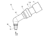
図1は本発明に係る塗装ロボットに装着した塗布ガンの側面図であり、塗布ガン10は、ロボットアーム11の先端部11aにホルダー12及びバルブユニット13を介してガン本体14を取付け、このガン本体14に塗料ノズル15を備えるノズルユニット16を取付けたものである。
バルブユニット13は、塗料ノズル15に供給する塗料の種類を切替えたり、塗料を洗浄液に切替えるバルブを内蔵したユニットである。
The best mode for carrying out the present invention will be described below with reference to the accompanying drawings.
FIG. 1 is a side view of a coating gun mounted on a painting robot according to the present invention. A
The
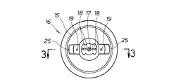
図2は図1の2矢視図であり、ノズルユニットの下面図であり、ノズルユニット16の中心に、塗料や洗浄液を噴射する噴射口17を供える塗料ノズル15を配置し、噴射ノズル17の外側左右に塗料をより細かくする複数の霧化ノズル18・・・(・・・は複数を示す。以下同じ。)を配置し、これらの霧化ノズル18・・・の外側左右に、噴霧パターンを調節するパターン調整ノズル19、19を設ける。
FIG. 2 is a bottom view of the nozzle unit in FIG. 2, and is a bottom view of the nozzle unit. In the center of the
図3は図2の3−3線断面図であり、ノズルユニット16の詳細な構造を説明する図である。
ノズルユニット16は、中心に開け塗料ノズル15に備える噴射ノズル17に塗料を供給する塗料経路21と、この塗料経路21の周囲に設け霧化ノズル18・・・にエアを供給する霧化エア経路22と、この霧化エア経路22の周囲に設けパターン調整ノズル19、19にエアを供給するパターンエア経路23と、を備える。パターン調整ノズル19、19は、ノズルユニット16の下方に延設した延設部24、24に開けたエア噴射口であり、塗料ノズル15の中心軸25に対し角度θn、θnで内側に傾斜させて配置する。
3 is a cross-sectional view taken along line 3-3 in FIG. 2, and is a diagram illustrating the detailed structure of the
The
本実施例において、延設部24の外側の長さDは31mm、噴射ノズルの直径dは1mm、霧化ノズルの直径dmは0.8mm、パターン調整ノズルの直径dpは1.5〜1.8mmであり、角度θnは24°である。
In the present embodiment, the outside length D of the extended
以上に説明した塗布ガンの作用を次に述べる。
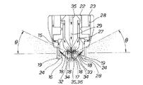
図4は塗布ガンの自己洗浄作用を説明する図である。
塗布ガンの前面32であるノズルユニット16の各噴射ノズル及びそれらの周辺を洗浄するため、霧化エア経路22に矢印27方向に霧化エア33を供給し、この霧化エア33を霧化ノズル18・・・から噴射させ、パターンエア経路23に矢印28方向にパターンエア34を供給し、このパターンエア34をパターン調整ノズル19、19から噴射させ、塗料経路21に矢印29方向に洗浄液としてのシンナー35を供給して、このシンナー35を塗料ノズル15に備える噴射ノズル17から噴射させる。
The operation of the coating gun described above will be described next.
FIG. 4 illustrates the self-cleaning action of the application gun.
In order to clean the spray nozzles of the
霧化エア経路22に、霧化エア33を供給して、霧化エア経路22への逆流を防止し、パターンエア経路23にパターンエア34を供給しながら、塗料経路21にシンナー35を供給することにより、塗料ノズル15から噴射したシンナー35にパターンエア経路23から噴射したパターンエア34を衝突させて、シンナー35を塗布ガンの前面32であるノズルユニット16の噴射ノズル17、霧化ノズル18及びパターン調整ノズル19の周囲を構成する面35に当て、この面35に付着した塗料を除去するようにした。
塗料ノズル15の自己洗浄が可能となるため、噴射ノズル15の外に設けた洗浄装置は不要となる。
The atomizing air 33 is supplied to the atomizing
Since the
すなわち、塗料ノズル15から塗料を噴射し、この塗料を霧化エア33で霧化し且つパターンエア34で噴射形状を整える形式の塗布ガン10を洗浄対象とする塗布ガン10の洗浄方法において、塗料を洗浄液36に交換すると共に噴射する洗浄液36が塗布ガン10の前面32を洗う噴射形状になるように、洗浄液36の噴射圧力Ps、霧化エア圧力Pm及びパターンエア圧力Ppを調節する。
That is, in the method of cleaning the
洗浄液36の噴射圧力Psは塗装条件と同じ圧力とし、霧化エア圧力Pmは低い圧力にして、塗布ガンの前面32に洗浄液36が付着し易いようにした。
そして、パターンエア圧力Ppは塗装条件と同じ圧力とし、洗浄液36の噴射パターンを調節し、洗浄液36が塗布ガンの前面32に強く当たるようにした。
この結果、塗装後の塗布ガンの前面32に付着した塗料に洗浄液36が当り、付着した塗料を除去することが可能となり、塗装品質が向上する。
The spraying pressure Ps of the cleaning
The pattern air pressure Pp was the same as the coating conditions, and the spray pattern of the cleaning
As a result, the cleaning liquid 36 hits the paint adhering to the
噴射ノズル17から洗浄液36を噴射して塗料を除去することで、従来、塗布ガンの外に設けた塗布ガン洗浄装置は不要となる。そのため、従来必要であった、洗浄装置の清掃などのメンテナンスによる塗装ラインの停止ロスを無くすことができる。
By spraying the cleaning
本実施例において、Psが4kg/cm2、Pmが0.1kg/cm2、Ppが3kg/cm2のとき、塗布ガンの前面32は良好に洗浄され、このときの洗浄液36の噴射パターンの水平面に対する角度θは、23°〜27°である。
In this embodiment, when Ps is 4 kg / cm 2 , Pm is 0.1 kg / cm 2 , and Pp is 3 kg / cm 2 , the
洗浄液36の噴射圧力Ps及びパターンエア34の圧力(パターンエア圧力Pp)は、塗装作業での圧力と同一にし、霧化エア33の圧力(霧化エア圧力Pm)は、塗装作業での噴射圧力の1/50〜1/20とする。
洗浄液36の噴射圧力Ps及びパターンエア圧力Ppを、塗装作業での圧力と同一にし、霧化エア圧力Pmは、塗装作業での圧力の1/50〜1/20に設定した。
The spray pressure Ps of the cleaning
The spray pressure Ps and the pattern air pressure Pp of the cleaning
霧化エア圧力Pmを、塗装作業での圧力の1/50未満に設定すると、霧化エア経路22に洗浄液36が逆流するという問題が起きる。
従って、霧化エア圧力Pmは、塗装作業での圧力の1/50以上に設定した。
If the atomizing air pressure Pm is set to be less than 1/50 of the pressure in the painting operation, there arises a problem that the cleaning
Therefore, the atomizing air pressure Pm was set to 1/50 or more of the pressure in the painting operation.
霧化エア圧力Pmを、塗装作業での圧力の1/20超に設定すると、霧化エア圧力Pmにより洗浄液36は塗布ガンの前面32に当らなくなる。
従って、霧化エア圧力Pmは、塗装作業での圧力の1/20以下に設定した。
When the atomizing air pressure Pm is set to more than 1/20 of the pressure in the painting operation, the cleaning
Therefore, the atomizing air pressure Pm was set to 1/20 or less of the pressure in the painting work.
すなわち、霧化エア圧力Pmを、塗装作業での圧力の1/50〜1/20に設定する。
霧化エア圧力Pmを、塗装作業での圧力の1/50〜1/20に設定することで、洗浄液36が、霧化エア経路23に逆流することはなく、塗布ガンの前面32への洗浄液36の十分な当り量を確保することができる。
That is, the atomizing air pressure Pm is set to 1/50 to 1/20 of the pressure in the painting operation.
By setting the atomizing air pressure Pm to 1/50 to 1/20 of the pressure in the painting operation, the cleaning
塗布ガンの前面32への洗浄液36の十分な当り量を確保することができれば、塗布ガンの洗浄時間そのものを大幅に短縮させると共に、塗布ガン洗浄装置への塗布ガンのセットアップ時間は不要となる。
この結果、塗布ガンの前面32を短時間で洗浄することができるようになる。
If a sufficient amount of the cleaning
As a result, the
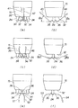
図5はパターンエア圧力Ppを変化させたときの噴霧パターンを説明する図であり、パターンエア圧力により、ノズルユニット16に備える塗料ノズル15から噴射させた洗浄液36の噴霧パターンが大きく変化することを示す。
FIG. 5 is a diagram for explaining a spray pattern when the pattern air pressure Pp is changed, and that the spray pattern of the cleaning
(a)〜(f)において、霧化エア圧力Pmと洗浄液の噴射圧力Psは一定である。
すなわち、霧化エア経路22(図2参照)に、0.1kg/cm2の圧力でエアを供給し、塗料経路21に4kg/cm2の圧力で洗浄液を供給し、塗料ノズル15から噴射した洗浄液36にパターンエア経路23からパターンエア34を噴射、衝突させて、洗浄液36を塗布ガンの前面32に向けて舞上げ、塗布ガンの前面32を洗浄しようとするものである。
In (a) to (f), the atomizing air pressure Pm and the cleaning liquid injection pressure Ps are constant.
That is, air is supplied to the atomizing air path 22 (see FIG. 2) at a pressure of 0.1 kg / cm 2 , cleaning liquid is supplied to the
(a)は、パターンエア圧力Ppを4kg/cm2で噴射するときの噴霧パターンを示し、塗料ノズル15から噴射する洗浄液36は矢印41、42のように略垂直に舞い上がる。
(b)は、(a)を90°向きを変えた方向からみることを示し、洗浄液36は矢印43、44のように水平面に対してθbで上向きに舞い上がる。
本実施例において、θbは30°である。
(A) shows a spray pattern when spraying the pattern air pressure Pp at 4 kg / cm 2 , and the cleaning
(B) shows that (a) is seen from the direction changed by 90 °, and the cleaning
In this embodiment, θb is 30 °.
(c)は、パターンエア圧力Ppが3kg/cm2で噴射するときの噴霧パターンを示し、塗料ノズル15から噴射する洗浄液36は矢印45、46のように斜め上向きに舞い上がる。
(d)は、(c)を90°向きを変えた方向からみることを示し、洗浄液36は矢印47、48のように水平面に対してθdで上向きに舞い上がる。
本実施例において、θdは25°である。
(C) shows a spray pattern when the pattern air pressure Pp is sprayed at 3 kg / cm 2 , and the cleaning
(D) shows that (c) is seen from the direction changed by 90 °, and the cleaning
In this embodiment, θd is 25 °.
(e)は、パターンエア圧力Ppが1.5kg/cm2で噴射するときの噴霧パターンを示し、噴射ノズル15から噴射する洗浄液36は矢印51、52のように舞い上がることなく落下する。
(f)は、(e)を90°向きを変えた方向からみることを示し、洗浄液36は矢印53、54のように舞い上がることなく落下する。
(E) shows a spray pattern when the pattern air pressure Pp is sprayed at 1.5 kg / cm 2 , and the cleaning
(F) shows that (e) is seen from the direction changed by 90 °, and the cleaning
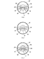
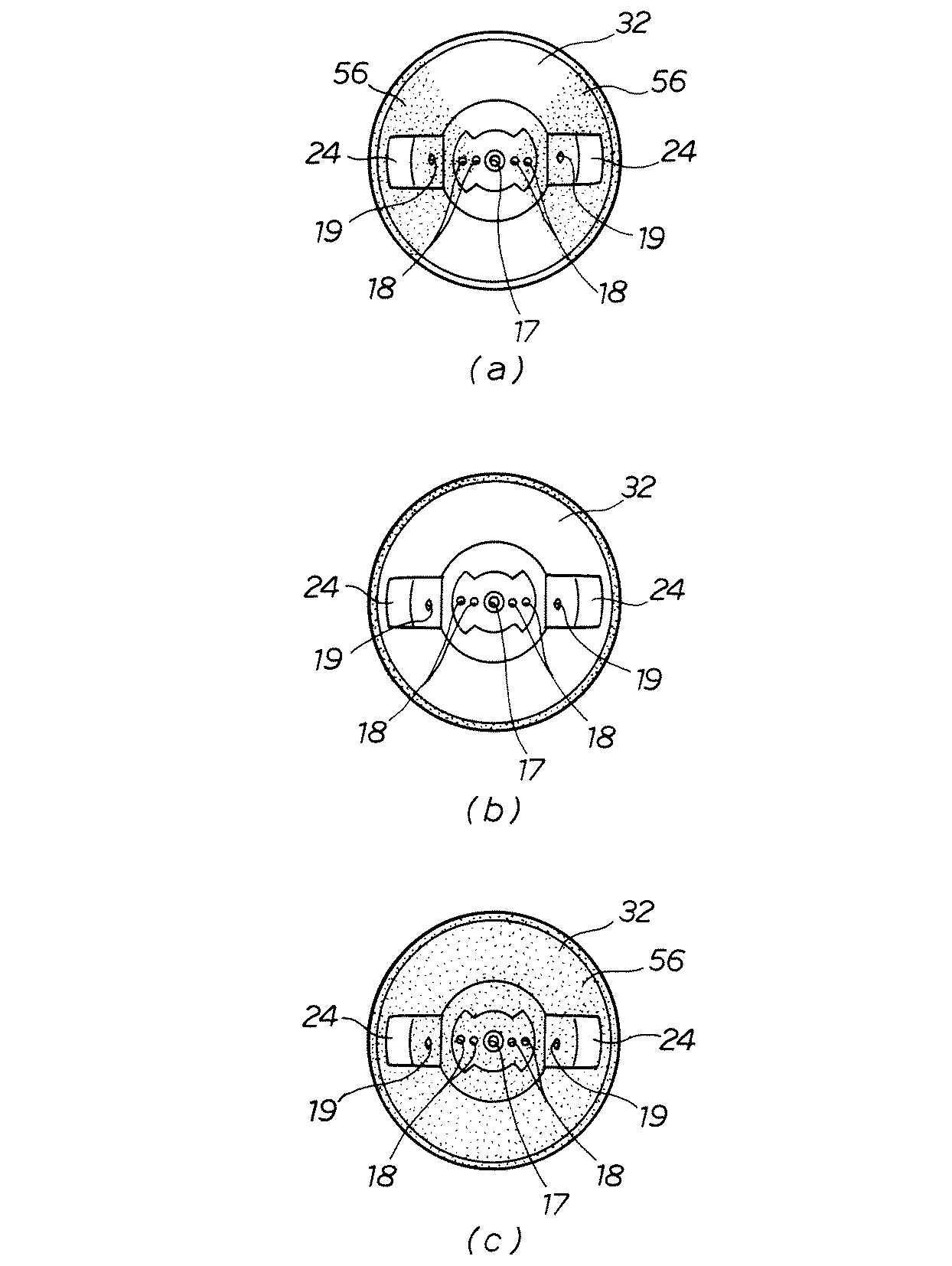
図6は塗布ガンの前面の洗浄結果を比較する図であり、洗浄液を塗布ガンの前面32に当てるとき、洗浄液の供給圧力と霧化エア圧力Pmは一定にし、パターンエア圧力Ppを変化させると塗布ガンの前面32の洗浄性能が異なることを説明する図である。
FIG. 6 is a diagram for comparing the cleaning results of the front surface of the coating gun. When the cleaning liquid is applied to the
(a)は図5(a)の条件で洗浄液を噴射したときに得られた結果であり、(b)は図5(c)の条件で洗浄液を噴射したときに得られた結果であり、(c)は図5(e)の条件で洗浄液を噴射したときに得られた結果である。 (A) is the result obtained when spraying the cleaning liquid under the conditions of FIG. 5 (a), (b) is the result obtained when spraying the cleaning liquid under the conditions of FIG. 5 (c), (C) is a result obtained when the cleaning liquid is jetted under the conditions of FIG.
(a)において、パターンエア圧力Ppが4kg/cm2のとき、塗布ガンの前面32に付着した塗料56・・・の一部は除去されないことを示す。
(b)において、パターンエア圧力Ppが3kg/cm2のとき、塗布ガンの前面32に付着した塗料は全て除去されることを示す。
(c)において、パターンエア圧力Ppが1.5kg/cm2のとき、塗布ガンの前面32に付着した塗料56・・・は除去されないことを示す。
In (a), when the pattern air pressure Pp is 4 kg / cm 2 , a part of the
(B), the time pattern air pressure Pp is 3 kg / cm 2, indicating that it is all removed paint is adhered to the
In (c), when the pattern air pressure Pp is 1.5 kg / cm 2 , the
パターンエア圧力Ppが強すぎると、洗浄液は塗布ガンの前面32の一部に偏って当たるので、洗浄は不十分となる。これとは反対に、パターンエア圧力Ppが弱いと、洗浄液の多くは舞い上がることなく落下し、塗布ガンの前面32を洗浄するまでには至らない。
If the pattern air pressure Pp is too strong, the cleaning liquid is biased to a part of the
このような、塗布ガンの洗浄方法を連続生産方式をとる塗装ラインに適用し、複数の被塗装物を塗装する合間に任意のタイミングで洗浄するようにすると、良好な塗装品質が得られると共に、塗布ガンの洗浄による塗装ラインの停止ロスを解消又は最小限に抑えることができる。 When such a coating gun cleaning method is applied to a coating line that adopts a continuous production method and cleaning is performed at an arbitrary timing between coating of a plurality of objects to be coated, good coating quality can be obtained, It is possible to eliminate or minimize the coating line stop loss due to the application gun cleaning.
例えば、塗布ガンの洗浄頻度が20〜30分毎に1回の洗浄を行うとき、本発明に係る塗布ガンの洗浄方法では、塗布ガンの前面を1回あたり20秒という短時間で洗浄することができる。 For example, when the coating gun is cleaned once every 20 to 30 minutes, the coating gun cleaning method according to the present invention cleans the front surface of the coating gun in a short time of 20 seconds per time. Can do.
従来、洗浄装置により塗布ガンの洗浄を行うと、洗浄に必要な時間は数倍必要であり、洗浄に時間を要していた。具体的には、塗装ラインにおいて、車両1台分の空きハンガーを流し、この空きハンガーが通過する間に塗布ガンの洗浄を行っていたので、塗装の生産性を低下させていた。生産性を低下させないため、塗布ガンの洗浄頻度を下げると、ノズルの詰まりや塗料カスの発生などにより塗装品質に影響するという問題があった。 Conventionally, when the application gun is cleaned by a cleaning device, the time required for cleaning is several times longer, and the cleaning takes time. Specifically, in the painting line, empty hangers for one vehicle were flowed, and the coating gun was washed while the empty hangers passed, so that the productivity of painting was reduced. In order not to reduce the productivity, if the frequency of cleaning the coating gun is lowered, there is a problem that the coating quality is affected by nozzle clogging or the generation of paint residue.
本発明に係る塗布ガンの洗浄方法によれば、塗布ガンの自動による自己洗浄が可能となり、塗布ガンの洗浄のために空きハンガーを入れることによる生産上のロスはなくなり、塗装ラインにおける生産能力の低下を回避することができる。
なお、洗浄するタイミングは、プログラムにより任意に変更可能である。
また、塗料の色を換える色換え時において、塗料経路及び噴射ノズルの洗浄並びに塗布ガン前面の洗浄を同時に行うことにより、洗浄時間を短縮することができる、
According to the method for cleaning an application gun according to the present invention, self-cleaning of the application gun is possible, and there is no loss in production due to the insertion of an empty hanger for cleaning the application gun. A decrease can be avoided.
The cleaning timing can be arbitrarily changed by a program.
Also, at the time of color change to change the color of the paint, the cleaning time can be shortened by simultaneously cleaning the paint path and the spray nozzle and the front of the coating gun,
本発明は、塗布ガンの洗浄に好適である。 The present invention is suitable for cleaning an application gun.
10…塗布ガン、15…塗料ノズル、32…塗布ガンの前面、33…霧化エア、34…パターンエア、36…洗浄液、56…塗料、洗浄液の噴射圧力…Ps、洗浄液の霧化エア圧力…Pm、洗浄液のパターンエア圧力…Pp。
DESCRIPTION OF
Claims (3)
前記塗料を洗浄液(36)に交換すると共に噴射する洗浄液(36)に、前記パターン調整ノズル(19)から噴射したパターンエア(34)を噴射、衝突させて、洗浄液(36)を塗布ガンの前面(32)に向けて舞上げ、洗浄液(36)が前記塗布ガンの前面(32)を洗う噴射形状になるように、洗浄液(36)の噴射圧力、霧化エア(33)の圧力及びパターンエア(34)の圧力を調節することを特徴とする塗布ガンの洗浄方法。 The paint is sprayed from the paint nozzle (15) , the paint is atomized by the atomizing air (33) sprayed from the atomizing nozzle (18), and inclined inward with respect to the central axis (25) of the paint nozzle (15). In the method for cleaning an application gun, the application gun (10) is of a type that uses a pattern air (34) sprayed from the pattern adjustment nozzle (19) arranged in this manner to adjust the spray shape.
The paint in the cleaning liquid (36) for injecting with exchanging the cleaning liquid (36), the pattern adjustment nozzles (19) from the injection pattern injecting the air (34), collide, the front surface of the coating gun cleaning liquid (36) (32) so that the cleaning liquid (36) has an injection shape for cleaning the front surface (32) of the coating gun, the spray pressure of the cleaning liquid (36) , the pressure of the atomizing air (33), and the pattern air (34) A method for cleaning an application gun, characterized by adjusting the pressure.
Priority Applications (8)
| Application Number | Priority Date | Filing Date | Title |
|---|---|---|---|
| JP2005197910A JP4171007B2 (en) | 2005-07-06 | 2005-07-06 | How to clean the application gun |
| PCT/JP2006/313640 WO2007004736A1 (en) | 2005-07-06 | 2006-07-04 | Method of washing paint gun |
| CNB2006800007771A CN100473466C (en) | 2005-07-06 | 2006-07-04 | Method of washing paint gun |
| DE602006005315T DE602006005315D1 (en) | 2005-07-06 | 2006-07-04 | METHOD FOR WASHING A COLOR SPRAY GUN |
| EP06768011A EP1793935B1 (en) | 2005-07-06 | 2006-07-04 | Method of washing a paint spray gun |
| US11/658,786 US20090205683A1 (en) | 2005-07-06 | 2006-07-04 | Method of Washing Paint Gun |
| CA002577716A CA2577716A1 (en) | 2005-07-06 | 2006-07-04 | Method of washing paint gun |
| BRPI0605899-0A BRPI0605899A (en) | 2005-07-06 | 2006-07-04 | Method for washing paint gun |
Applications Claiming Priority (1)
| Application Number | Priority Date | Filing Date | Title |
|---|---|---|---|
| JP2005197910A JP4171007B2 (en) | 2005-07-06 | 2005-07-06 | How to clean the application gun |
Publications (2)
| Publication Number | Publication Date |
|---|---|
| JP2007014863A JP2007014863A (en) | 2007-01-25 |
| JP4171007B2 true JP4171007B2 (en) | 2008-10-22 |
Family
ID=36933468
Family Applications (1)
| Application Number | Title | Priority Date | Filing Date |
|---|---|---|---|
| JP2005197910A Expired - Fee Related JP4171007B2 (en) | 2005-07-06 | 2005-07-06 | How to clean the application gun |
Country Status (8)
| Country | Link |
|---|---|
| US (1) | US20090205683A1 (en) |
| EP (1) | EP1793935B1 (en) |
| JP (1) | JP4171007B2 (en) |
| CN (1) | CN100473466C (en) |
| BR (1) | BRPI0605899A (en) |
| CA (1) | CA2577716A1 (en) |
| DE (1) | DE602006005315D1 (en) |
| WO (1) | WO2007004736A1 (en) |
Families Citing this family (7)
| Publication number | Priority date | Publication date | Assignee | Title |
|---|---|---|---|---|
| CN101314154A (en) * | 2008-07-01 | 2008-12-03 | 攀钢集团研究院有限公司 | A method for removing blockage of atomizer |
| WO2011019224A2 (en) * | 2009-08-12 | 2011-02-17 | 엘지전자 주식회사 | Method for diagnosing 3d state information, and broadcast receiver |
| JP2014184357A (en) * | 2013-03-21 | 2014-10-02 | Toshiba Corp | Nozzle cleaning unit and nozzle cleaning method |
| CN104069976B (en) * | 2014-06-11 | 2016-08-24 | 华南理工大学 | A kind of atomizer removing nozzle kiss-coating |
| JP6392177B2 (en) * | 2015-06-29 | 2018-09-19 | 株式会社パウレック | Spray nozzle and cleaning method thereof |
| JP6270896B2 (en) * | 2016-03-29 | 2018-01-31 | 本田技研工業株式会社 | COATING NOZZLE, COATING DEVICE, AND COATING METHOD USING THEM |
| TWI768600B (en) * | 2020-12-17 | 2022-06-21 | 魏榮宗 | Exhaust gas purification system |
Family Cites Families (10)
| Publication number | Priority date | Publication date | Assignee | Title |
|---|---|---|---|---|
| JPS6349270A (en) * | 1986-08-14 | 1988-03-02 | Toyota Motor Corp | Color changing and cleaning device for mini-bell type coater |
| DE3720200A1 (en) * | 1987-06-16 | 1988-12-29 | Ransburg Gmbh | SPRAY COATING DEVICE WITH A ROTATIONAL SPRAY ORGAN |
| DE3808801A1 (en) * | 1988-03-16 | 1989-10-05 | Behr Industrieanlagen | METHOD AND DEVICE FOR CLEANING A SPRAYING DEVICE |
| JPH01262964A (en) | 1988-04-15 | 1989-10-19 | Hitachi Ltd | automatic nozzle cleaner |
| EP0882585A1 (en) * | 1997-06-03 | 1998-12-09 | Schablonentechnik Kufstein Aktiengesellschaft | Method and device for the production of a pattern on a support |
| US6267302B1 (en) * | 1999-05-17 | 2001-07-31 | David Clark Huffman | Spray gun with rolling wall diaphragm and quick disconnect housing |
| ATE332756T1 (en) * | 2002-12-20 | 2006-08-15 | Lifecycle Pharma As | SELF-CLEANING SPRAY NOZZLE |
| US6874708B2 (en) * | 2003-02-13 | 2005-04-05 | Illinois Tool Works Inc. | Automatic air-assisted manifold mounted gun |
| US20070262172A1 (en) * | 2003-03-27 | 2007-11-15 | Spraying Systems Co. | Modular Spray Gun with Multiple Control Modules |
| US20050040257A1 (en) * | 2003-08-19 | 2005-02-24 | Seitz David M. | Atomizer with dedicated cleaning fluid system |
-
2005
- 2005-07-06 JP JP2005197910A patent/JP4171007B2/en not_active Expired - Fee Related
-
2006
- 2006-07-04 WO PCT/JP2006/313640 patent/WO2007004736A1/en not_active Ceased
- 2006-07-04 BR BRPI0605899-0A patent/BRPI0605899A/en not_active IP Right Cessation
- 2006-07-04 CA CA002577716A patent/CA2577716A1/en not_active Abandoned
- 2006-07-04 CN CNB2006800007771A patent/CN100473466C/en not_active Expired - Fee Related
- 2006-07-04 EP EP06768011A patent/EP1793935B1/en not_active Not-in-force
- 2006-07-04 US US11/658,786 patent/US20090205683A1/en not_active Abandoned
- 2006-07-04 DE DE602006005315T patent/DE602006005315D1/en not_active Expired - Fee Related
Also Published As
| Publication number | Publication date |
|---|---|
| WO2007004736A1 (en) | 2007-01-11 |
| CA2577716A1 (en) | 2007-01-11 |
| EP1793935B1 (en) | 2009-02-25 |
| JP2007014863A (en) | 2007-01-25 |
| DE602006005315D1 (en) | 2009-04-09 |
| EP1793935A1 (en) | 2007-06-13 |
| CN100473466C (en) | 2009-04-01 |
| US20090205683A1 (en) | 2009-08-20 |
| CN101018613A (en) | 2007-08-15 |
| BRPI0605899A (en) | 2007-12-18 |
Similar Documents
| Publication | Publication Date | Title |
|---|---|---|
| KR102458213B1 (en) | Application head of a coating product on a surface to be coated | |
| EP1847207A3 (en) | Wash/rinse system for a drawer-type dishwasher | |
| JP5989489B2 (en) | Coating machine cleaning mechanism, coating machine cleaning method | |
| JP4171007B2 (en) | How to clean the application gun | |
| JP2010269214A (en) | Nozzle cleaning device | |
| JP2015157244A (en) | Spray gun | |
| JP6005497B2 (en) | Rotary atomizing head type coating machine | |
| JP2013071077A (en) | Cleaning device and cleaning method of painting gun | |
| JP2009525853A (en) | Cleaning assembly | |
| CN1326631C (en) | Rotation type atomization spraying device | |
| JP5198826B2 (en) | Cleaning device | |
| CN111511477A (en) | Cleaning method of spray gun | |
| JPH07284702A (en) | Paint gun cleaning equipment | |
| CN116921340A (en) | Cleaning method of cleaning device and spray gun | |
| JP2011125805A (en) | Nozzle for rotary gun | |
| US7137573B2 (en) | Rotary atomization coating apparatus | |
| JPH08299896A (en) | Painting of building panel | |
| CN211756086U (en) | Spray nozzle | |
| JP6783366B1 (en) | Painting machine, painting system, and painting machine control method | |
| JP2008013869A (en) | Spinneret cleaning equipment | |
| JP2011230034A (en) | Apparatus and method of cleaning rotary atomizing head | |
| JPH09192546A (en) | Rotary atomizing head backside cleaning method of rotary atomizing electrostatic coating equipment | |
| WO2007000853A1 (en) | Bell type coating device | |
| JP3193901B2 (en) | Air airless gun | |
| JP5688610B2 (en) | Blasting nozzle and blasting device |
Legal Events
| Date | Code | Title | Description |
|---|---|---|---|
| A131 | Notification of reasons for refusal |
Free format text: JAPANESE INTERMEDIATE CODE: A131 Effective date: 20080422 |
|
| A521 | Request for written amendment filed |
Free format text: JAPANESE INTERMEDIATE CODE: A523 Effective date: 20080618 |
|
| TRDD | Decision of grant or rejection written | ||
| A01 | Written decision to grant a patent or to grant a registration (utility model) |
Free format text: JAPANESE INTERMEDIATE CODE: A01 Effective date: 20080805 |
|
| A01 | Written decision to grant a patent or to grant a registration (utility model) |
Free format text: JAPANESE INTERMEDIATE CODE: A01 |
|
| A61 | First payment of annual fees (during grant procedure) |
Free format text: JAPANESE INTERMEDIATE CODE: A61 Effective date: 20080807 |
|
| FPAY | Renewal fee payment (event date is renewal date of database) |
Free format text: PAYMENT UNTIL: 20110815 Year of fee payment: 3 |
|
| R150 | Certificate of patent or registration of utility model |
Free format text: JAPANESE INTERMEDIATE CODE: R150 |
|
| FPAY | Renewal fee payment (event date is renewal date of database) |
Free format text: PAYMENT UNTIL: 20110815 Year of fee payment: 3 |
|
| FPAY | Renewal fee payment (event date is renewal date of database) |
Free format text: PAYMENT UNTIL: 20120815 Year of fee payment: 4 |
|
| LAPS | Cancellation because of no payment of annual fees |