JP4158111B2 - Pneumatic switching type fluid-filled engine mount - Google Patents
Pneumatic switching type fluid-filled engine mount Download PDFInfo
- Publication number
- JP4158111B2 JP4158111B2 JP2004160332A JP2004160332A JP4158111B2 JP 4158111 B2 JP4158111 B2 JP 4158111B2 JP 2004160332 A JP2004160332 A JP 2004160332A JP 2004160332 A JP2004160332 A JP 2004160332A JP 4158111 B2 JP4158111 B2 JP 4158111B2
- Authority
- JP
- Japan
- Prior art keywords
- receiving chamber
- pressure receiving
- movable
- outer peripheral
- fluid
- Prior art date
- Legal status (The legal status is an assumption and is not a legal conclusion. Google has not performed a legal analysis and makes no representation as to the accuracy of the status listed.)
- Expired - Fee Related
Links
- 239000012530 fluid Substances 0.000 title claims description 107
- 238000005192 partition Methods 0.000 claims description 136
- 230000002093 peripheral effect Effects 0.000 claims description 103
- 238000006073 displacement reaction Methods 0.000 claims description 42
- 238000004891 communication Methods 0.000 claims description 17
- 230000001105 regulatory effect Effects 0.000 claims description 14
- 230000000903 blocking effect Effects 0.000 claims description 7
- 230000008859 change Effects 0.000 claims description 5
- 239000000463 material Substances 0.000 claims description 5
- 239000012528 membrane Substances 0.000 claims description 5
- 230000003139 buffering effect Effects 0.000 claims description 2
- 230000009471 action Effects 0.000 description 35
- 230000000694 effects Effects 0.000 description 29
- 239000002184 metal Substances 0.000 description 24
- 238000010521 absorption reaction Methods 0.000 description 16
- 238000013016 damping Methods 0.000 description 10
- 238000002955 isolation Methods 0.000 description 10
- 230000006835 compression Effects 0.000 description 5
- 238000007906 compression Methods 0.000 description 5
- 230000005489 elastic deformation Effects 0.000 description 4
- 230000000452 restraining effect Effects 0.000 description 4
- 238000009413 insulation Methods 0.000 description 3
- 229920003002 synthetic resin Polymers 0.000 description 3
- 239000000057 synthetic resin Substances 0.000 description 3
- -1 alkylene glycol Chemical compound 0.000 description 2
- 230000015572 biosynthetic process Effects 0.000 description 2
- 230000001276 controlling effect Effects 0.000 description 2
- 238000011067 equilibration Methods 0.000 description 2
- 230000001133 acceleration Effects 0.000 description 1
- 238000005452 bending Methods 0.000 description 1
- 230000009194 climbing Effects 0.000 description 1
- 238000002485 combustion reaction Methods 0.000 description 1
- 230000008878 coupling Effects 0.000 description 1
- 238000010168 coupling process Methods 0.000 description 1
- 238000005859 coupling reaction Methods 0.000 description 1
- 238000007599 discharging Methods 0.000 description 1
- LYCAIKOWRPUZTN-UHFFFAOYSA-N ethylene glycol Natural products OCCO LYCAIKOWRPUZTN-UHFFFAOYSA-N 0.000 description 1
- 230000001747 exhibiting effect Effects 0.000 description 1
- WGCNASOHLSPBMP-UHFFFAOYSA-N hydroxyacetaldehyde Natural products OCC=O WGCNASOHLSPBMP-UHFFFAOYSA-N 0.000 description 1
- 238000004519 manufacturing process Methods 0.000 description 1
- 238000012986 modification Methods 0.000 description 1
- 230000004048 modification Effects 0.000 description 1
- 230000000149 penetrating effect Effects 0.000 description 1
- 229920001515 polyalkylene glycol Polymers 0.000 description 1
- 230000003014 reinforcing effect Effects 0.000 description 1
- 230000004044 response Effects 0.000 description 1
- 238000000926 separation method Methods 0.000 description 1
- 229920002545 silicone oil Polymers 0.000 description 1
- 230000001960 triggered effect Effects 0.000 description 1
- XLYOFNOQVPJJNP-UHFFFAOYSA-N water Substances O XLYOFNOQVPJJNP-UHFFFAOYSA-N 0.000 description 1
Images


Description
本発明は、自動車においてパワーユニットを車両ボデーに対して防振支持せしめるエンジンマウントに係り、特に内部に封入された非圧縮性流体の流動作用を利用してエンジンシェイクやアイドリング振動等の複数の乃至は広い周波数域の振動に対して有効な防振効果が発揮され得る、改良された構造の流体封入式エンジンマウントに関するものである。 The present invention relates to an engine mount that supports a power unit in a vehicle in a vibration-proof manner with respect to a vehicle body, and in particular, uses a flow action of an incompressible fluid sealed inside to provide a plurality of or shakes such as engine shake and idling vibration. The present invention relates to a fluid-filled engine mount having an improved structure capable of exhibiting an effective vibration-proofing effect against vibrations in a wide frequency range.
従来から、自動車用のエンジンマウントの一種として、パワーユニットと車両ボデーの各一方に取り付けられる第一の取付金具と第二の取付金具を本体ゴム弾性体で相互に連結させて、該本体ゴム弾性体で壁部の一部が構成された受圧室と変形容易な可撓性膜で壁部の一部が構成された平衡室を形成し、それら受圧室と平衡室に非圧縮性流体を封入すると共に、両室を相互に連通させるオリフィス通路を設けた流体封入式のエンジンマウントが知られている。 Conventionally, as a kind of engine mount for automobiles, a first mounting bracket and a second mounting bracket that are attached to one of a power unit and a vehicle body are connected to each other by a main rubber elastic body, and the main rubber elastic body Forming a pressure receiving chamber in which a part of the wall is configured and an equilibrium chamber in which a part of the wall is configured by a flexible film that is easily deformable, and enclosing an incompressible fluid in the pressure receiving chamber and the equilibrium chamber. In addition, a fluid-filled engine mount provided with an orifice passage that allows the two chambers to communicate with each other is known.
ところで、自動車用のエンジンマウントにおいては、走行状態等に応じて防振すべき振動の周波数が異なる場合が多い。しかし、オリフィス通路を通じて流動せしめられる流体の流動作用に基づいて発揮される防振効果は、予めオリフィス通路がチューニングされた比較的に狭い周波数域に限られる。 By the way, in an engine mount for an automobile, the frequency of vibrations to be vibrated is often different depending on a traveling state or the like. However, the anti-vibration effect exerted on the basis of the flow action of the fluid flowing through the orifice passage is limited to a relatively narrow frequency range in which the orifice passage is tuned in advance.
そこで、このような問題に対処するために、シェイク等に相当する低周波数域にチューニングした第一のオリフィス通路とアイドリング振動等に相当する中周波数域にチューニングした第二のオリフィス通路を、受圧室と平衡室の間に形成すると共に、空気圧アクチュエータで駆動される弁手段で第二のオリフィス通路を開閉するようにした空気圧切換型の流体封入式エンジンマウントが提案されている。かかるエンジンマウントにおいては、空気圧式アクチュエータを入力振動に応じて制御することにより、第一のオリフィス通路と第二のオリフィス通路を選択的に機能させることが出来る。 Therefore, in order to cope with such a problem, a pressure receiving chamber is provided with a first orifice passage tuned to a low frequency range corresponding to a shake or the like and a second orifice passage tuned to a medium frequency range corresponding to idling vibration or the like. There is proposed a pneumatically-switched fluid-filled engine mount that is formed between the balance chamber and the equilibrium chamber and is configured to open and close the second orifice passage by a valve means driven by a pneumatic actuator. In such an engine mount, the first orifice passage and the second orifice passage can be selectively made to function by controlling the pneumatic actuator according to the input vibration.
ところが、近年では、自動車の静穏化志向等に伴い一層高度な防振性能が要求されるようになってきており、上述の如き構造とされた空気圧切換型のエンジンマウントであっても要求される防振性能を未だ充分に実現できていないところがある。 However, in recent years, a higher level of anti-vibration performance has been demanded in response to the calmness of automobiles, and even a pneumatically switched engine mount having the above-described structure is also required. There is a place where the anti-vibration performance has not been realized yet.
その実現に至っていない一つの要求性能が、走行時に問題となる走行こもり音等の高周波振動に対する防振性能である。即ち、高周波振動の入力時には、低周波数域や中周波数域にチューニングされた第一のオリフィス通路や第二のオリフィス通路が実質的に閉塞状態となってしまって著しく高動ばね化することにより、防振性能が低下してしまうという問題がある。 One required performance that has not yet been realized is an anti-vibration performance against high-frequency vibrations such as a running-over noise that becomes a problem during traveling. That is, at the time of high frequency vibration input, the first orifice passage and the second orifice passage tuned to the low frequency range and the middle frequency range are substantially closed, resulting in a highly dynamic spring. There is a problem that the anti-vibration performance deteriorates.
そこで、このような要求特性に対処するために、高周波数域で問題となる振動が一般に小振幅であることに着目し、例えば本願出願人の先願に係る特開2000−310274号公報(特許文献1)や特開2001−200884号公報(特許文献2)等にも示されているように、隔壁部材に対して受圧室と平衡室の対向方向に略直角に広がる可動板を小変位可能に配設して、第一のオリフィス通路や第二のオリフィス通路のチューニング周波数域を越えた高周波数域の振動入力時における受圧室の圧力変動を可動板の微小な変位で吸収させて、低動ばね化を図ることが考えられる。 Therefore, in order to deal with such required characteristics, attention is paid to the fact that the vibration which is a problem in the high frequency range generally has a small amplitude. For example, Japanese Patent Application Laid-Open No. 2000-310274 (patent) As shown in Document 1) and Japanese Patent Application Laid-Open No. 2001-200804 (Patent Document 2), the movable plate that extends substantially perpendicularly to the opposing direction of the pressure receiving chamber and the equilibrium chamber can be slightly displaced with respect to the partition member. The pressure fluctuation of the pressure receiving chamber at the time of vibration input in the high frequency range exceeding the tuning frequency range of the first orifice passage and the second orifice passage is absorbed by the minute displacement of the movable plate, It is conceivable to use a dynamic spring.
ところが、このような可動板を採用した場合に、低乃至中周波数域の振動の入力時等にまで受圧室の圧力変動が可動板の変位で吸収されてしまうおそれがある。 However, when such a movable plate is used, the pressure fluctuation in the pressure receiving chamber may be absorbed by the displacement of the movable plate even at the time of inputting vibrations in the low to medium frequency range.
すなわち、アイドリング等の中周波数域の振動は、その振幅が一般に±0.1〜0.25mmと比較的に小さい。また、走行時に問題となるエンジンシェイク等の低周波数域の振動も、従来から問題となっていた段差乗り越え等に際して発生する±1. 0mm程度の大振幅に加えて、近年では、通常走行時に発生する±0.1mm程度の小振幅に対しても有効な防振効果が要求されるようになってきている。そのために、このような振幅の比較的小さい低〜中周波数域の振動に関しては、可動板の小変位に伴って受圧室の圧力変動が吸収されてしまうと、第一のオリフィス通路や第二のオリフィス通路を通じての流体流動量が少なくなって、十分な防振効果を得ることが出来なくなるおそれがあるのである。 That is, the vibration of the medium frequency range such as idling has a relatively small amplitude of ± 0.1 to 0.25 mm in general. In addition, vibrations in the low frequency range such as engine shake, which is a problem during driving, have also occurred during normal driving in recent years, in addition to the large amplitude of about ± 1.0 mm that occurs when overcoming a step, which has been a problem in the past. Effective anti-vibration effects are required even for small amplitudes of about ± 0.1 mm. For this reason, with respect to such low-to-medium frequency vibrations having a relatively small amplitude, if the pressure fluctuation in the pressure receiving chamber is absorbed along with the small displacement of the movable plate, the first orifice passage and the second There is a possibility that the amount of fluid flow through the orifice passage is reduced, and a sufficient vibration-proofing effect cannot be obtained.
ここにおいて、本発明は、上述の如き事情を背景として為されたものであって、その解決課題とするところは、低周波数域にチューニングされた第一のオリフィス通路や中周波数域にチューニングされた第二のオリフィス通路による防振効果を十分に確保しつつ、高周波数域の著しい高動ばね化が軽減乃至は回避されて、複数の乃至は広い周波数域の振動に対して有効な防振効果が発揮され得る、新規な構造の空気圧切換型の流体封入式エンジンマウントを提供することにある。 Here, the present invention has been made against the background as described above, and the problem to be solved is that the first orifice passage tuned to the low frequency region and the medium frequency region are tuned. While ensuring sufficient vibration isolation effect by the second orifice passage, significant high dynamic springs in the high frequency range are reduced or avoided, and effective for vibrations in multiple or wide frequency ranges. It is an object of the present invention to provide a pneumatic switching type fluid-filled engine mount having a novel structure.
以下、このような課題を解決するために為された本発明の態様を記載する。なお、以下に記載の各態様において採用される構成要素は、可能な限り任意の組み合わせで採用可能である。また、本発明の態様乃至は技術的特徴は、以下に記載のものに限定されることなく、明細書全体および図面に記載されたもの、或いはそれらの記載から当業者が把握することの出来る発明思想に基づいて認識されるものであることが理解されるべきである。 Hereinafter, the aspect of this invention made | formed in order to solve such a subject is described. In addition, the component employ | adopted in each aspect as described below is employable by arbitrary combinations as much as possible. Further, aspects or technical features of the present invention are not limited to those described below, but are described in the entire specification and drawings, or an invention that can be understood by those skilled in the art from those descriptions. It should be understood that it is recognized based on thought.
(本発明の態様1)
本発明の態様1の特徴とするところは、(a)パワーユニット側部材と車両ボデー側部材の一方に取り付けられる第一の取付部材と、(b)それらパワーユニット側部材と車両ボデー側部材の他方に取り付けられる第二の取付部材と、(c)前記第一の取付部材と前記第二の取付部材を弾性的に連結する本体ゴム弾性体と、(d)該本体ゴム弾性体によって壁部の一部が構成されて振動が入力される、非圧縮性流体が封入された受圧室と、(e)壁部の一部が可撓性膜で構成されて容積変化が容易に許容される、非圧縮性流体が封入された平衡室と、(f)前記受圧室と前記平衡室を相互に連通せしめる、エンジンシェイクに略相当する低周波数域にチューニングされた第一のオリフィス通路と、(g)前記受圧室と前記平衡室を相互に連通せしめる、アイドリング振動に略相当する中周波数域にチューニングされた第二のオリフィス通路と、(h)該第二のオリフィス通路を連通/遮断する弁手段と、(i)外部から及ぼされる空気圧で作動せしめられて前記弁手段を駆動する空気圧式アクチュエータと、(j)中央部分が硬質の中央可動板部とされていると共に外周部分が変形容易な外周可動ゴム膜部とされており、該外周可動ゴム膜部の外周縁部において前記第二の取り付け部材で実質的に流体密に支持されて前記受圧室と前記平衡室を仕切るようにして配設せしめられ、その一方の面側に形成された該受圧室と他方の面側に形成された該平衡室との圧力差に基づいて該中央可動板部および該外周可動ゴム膜部の変位乃至は変形が許容されるように配設されて、かかる変位乃至は変形によって走行こもり音に略相当する高周波数域の振動入力時における該受圧室の圧力変動を吸収する可動仕切部材とを、有しており、且つ、前記平衡室の一部を狭窄せしめて流体流路を形成して、前記可動仕切部材の両面に及ぼされる前記受圧室と前記平衡室の圧力差に基づく該可動仕切部材の変位乃至は変形に基づいて該流体流路を通じての実質的な流体流動が許容されるようにした空気圧切換型の流体封入式エンジンマウントにある。
(Aspect 1 of the present invention)
A feature of aspect 1 of the present invention is that (a) a first attachment member attached to one of the power unit side member and the vehicle body side member, and (b) the other of the power unit side member and the vehicle body side member. A second mounting member to be mounted; (c) a main rubber elastic body that elastically connects the first mounting member and the second mounting member; and (d) one of the wall portions by the main rubber elastic body. A pressure receiving chamber in which an incompressible fluid is sealed, in which vibration is input, and (e) a part of the wall portion is formed of a flexible film, and volume change is easily allowed. An equilibrium chamber filled with a compressible fluid; and (f) a first orifice passage tuned to a low frequency range substantially corresponding to an engine shake, which allows the pressure receiving chamber and the equilibrium chamber to communicate with each other; and (g) The pressure receiving chamber and the equilibrium chamber communicate with each other A second orifice passage tuned to an intermediate frequency range substantially corresponding to idling vibration, (h) valve means for communicating / blocking the second orifice passage, and (i) operated by air pressure exerted from the outside. And (j) the central portion is a rigid central movable plate portion and the outer peripheral portion is an easily movable outer peripheral movable rubber film portion, and is movable around the outer periphery. The outer peripheral edge portion of the rubber film portion is substantially fluid-tightly supported by the second mounting member, and is arranged so as to partition the pressure receiving chamber and the equilibrium chamber, and is formed on one surface side thereof. Based on the pressure difference between the pressure receiving chamber and the equilibrium chamber formed on the other surface side, the central movable plate portion and the outer peripheral movable rubber film portion are disposed so as to allow displacement or deformation, Such displacement It is a movable partition member for absorbing the pressure fluctuations of the receiving chamber in a substantially equivalent when the vibration input in the high frequency band in the booming noise due to the deformation, perforated and has, and, by allowed narrowing a part of the equilibrium chamber A fluid flow path is formed, and a substantial flow through the fluid flow path is determined based on a displacement or deformation of the movable partition member based on a pressure difference between the pressure receiving chamber and the equilibrium chamber exerted on both surfaces of the movable partition member. A pneumatically switched fluid-filled engine mount that allows fluid flow .
このような本態様に従う構造とされた流体封入式エンジンマウントにおいては、可動仕切部材の中央部分が、第二の取付部材等に支持される外周縁部から離れた位置にあることに起因して受圧室の振動入力に伴い変形され易い傾向にあるが、かかる中央部分に硬質の中央可動板部が設けられていることによって、可動仕切部材の変形量が好適に抑えられる。また、可動仕切部材の中央部分が硬質とされていることにより、該可動仕切部材を大きくしても過度の変形が抑えられる。それ故、特に受圧室に対して有効な圧力変動が惹起されることが望ましい低乃至中周波数域の振動入力時にあっては、入力振動の振幅がある程度まで小さくても可動仕切部材による液圧吸収が効果的に抑制されて、受圧室の圧力変動が有効に生ぜしめられる。 In the fluid-filled engine mount having the structure according to this aspect, the center portion of the movable partition member is located away from the outer peripheral edge supported by the second mounting member or the like. Although it tends to be easily deformed with the vibration input of the pressure receiving chamber, the amount of deformation of the movable partition member is suitably suppressed by providing a hard central movable plate portion at the central portion. Further, since the central portion of the movable partition member is hard, excessive deformation can be suppressed even if the movable partition member is enlarged. Therefore, it is desirable for effective pressure fluctuations to be induced in the pressure receiving chamber, especially during low to medium frequency vibration input, even if the amplitude of the input vibration is small to some extent, the hydraulic pressure absorption by the movable partition member Is effectively suppressed, and the pressure fluctuation in the pressure receiving chamber is effectively generated.
また、中央可動板部の外周部分に変形容易な外周可動ゴム膜部が配設されていることによって、特に受圧室における高周波数域の振動入力時には、主として外周可動ゴム膜部の変形に基づいて、高周波振動に対して追従するように可動仕切部材が変位乃至は変形せしめられることとなり、受圧室の圧力変動が有利に抑えられる。 In addition, since the outer peripheral movable rubber film part that is easily deformable is disposed on the outer peripheral part of the central movable plate part, particularly when vibration is input in a high frequency range in the pressure receiving chamber, mainly based on the deformation of the outer peripheral movable rubber film part. Thus, the movable partition member is displaced or deformed so as to follow the high frequency vibration, and the pressure fluctuation in the pressure receiving chamber is advantageously suppressed.
従って、例えば段差乗越え時に発生するエンジンシェイク等に相当する低周波大振幅振動が入力される際には、可動仕切部材の変位乃至は変形による液圧吸収が追従し得ずに受圧室には有効な圧力変動が惹起されることとなって、受圧室と平衡室の間に相対的な圧力変動が有効に生ぜしめられる。それ故、第二のオリフィス通路を弁手段で遮断状態に維持することによって、第一のオリフィス通路を通じての流体流動が十分に確保されて、第一のオリフィス通路を流動せしめられる流体の共振作用等の流動作用に基づく振動減衰効果が有利に発揮され得る。 Therefore, for example, when low-frequency, large-amplitude vibration corresponding to engine shake that occurs when stepping over a level difference is input, the absorption of the hydraulic pressure due to displacement or deformation of the movable partition member cannot follow and is effective for the pressure receiving chamber. Thus, a relative pressure fluctuation is effectively generated between the pressure receiving chamber and the equilibrium chamber. Therefore, by maintaining the second orifice passage in the shut-off state by the valve means, the fluid flow through the first orifice passage is sufficiently ensured, and the resonance action of the fluid that can flow through the first orifice passage, etc. The vibration damping effect based on the fluid action can be advantageously exhibited.
また、例えば通常走行時に発生するエンジンシェイク等に相当する低周波小振幅振動が入力されるに際しては、可動仕切部材による受圧室の圧力吸収が懸念されるが、中央可動板部の外周側における流体密性が外周可動ゴム膜部の外周縁部が実質的に流体密に支持されていることで確保されていることと、中央可動板部が硬質とされて変形量が抑えられていることによって、可動仕切部材による受圧室の圧力吸収が抑えられることから、受圧室には未だ十分に有効な圧力変動が惹起されることとなる。それ故、上述の低周波大振幅振動の場合と同様に、第二のオリフィス通路を弁手段で遮断状態にすれば、第一のオリフィス通路を通じての流体流動量が有利に確保され得て、第一のオリフィス通路を流動せしめられる流体の共振作用等の流動作用に基づく高減衰効果が発揮され得る。 In addition, when low-frequency small-amplitude vibration corresponding to, for example, an engine shake that occurs during normal traveling is input, there is a concern about the pressure absorption of the pressure receiving chamber by the movable partition member, but the fluid on the outer peripheral side of the central movable plate portion By ensuring that the outer periphery of the outer peripheral movable rubber film part is substantially fluid-tightly supported and that the central movable plate part is hard and the deformation amount is suppressed. Since the pressure absorption of the pressure receiving chamber by the movable partition member is suppressed, a sufficiently effective pressure fluctuation is still induced in the pressure receiving chamber. Therefore, as in the case of the low-frequency large-amplitude vibration described above, if the second orifice passage is blocked by the valve means, the amount of fluid flow through the first orifice passage can be advantageously ensured, and the first A high damping effect based on a flow action such as a resonance action of a fluid flowing through one orifice passage can be exhibited.
さらに、例えば走行時に発生する走行こもり音等に相当する高周波微小振幅振動が入力される際には、受圧室の圧力変動が非常に小さいことから、可動仕切部材の変位乃至は変形に基づいて受圧室の圧力変動が軽減され得る。特に、可動仕切部材の中央可動板部が中央部分に形成されていることによって中央可動板部の有効面積が有利に確保されていると共に、該可動板部の外周部分に設けられた外周可動ゴム膜部が変形容易とされていることから、受圧室における高周波数域の振動に対して追従するように変位乃至は変形されて、受圧室の圧力変動が有利に抑えられる。それ故、高周波数域の振動入力時には、第一及び第二のオリフィス通路が実質的に閉塞された状態下にあっても、受圧室の著しい圧力変動が可動仕切部材によって回避されて、低動ばね特性に基づく振動絶縁効果が有効に発揮され得る。なお、可動仕切部材の固有振動数が、例えば走行こもり音等に相当する高周波数域にチューニングされることによって、該高周波振動の入力時に可動仕切部材の共振作用に基づいて可動仕切部材が一層好適に変位乃至は変形されることとなり、受圧室における圧力変動の抑制作用がより有効に機能され得る。 Furthermore, for example, when a high-frequency minute amplitude vibration corresponding to a traveling booming noise generated during traveling is input, the pressure fluctuation in the pressure receiving chamber is very small, so that the pressure receiving is based on the displacement or deformation of the movable partition member. Chamber pressure fluctuations can be reduced. In particular, since the central movable plate portion of the movable partition member is formed in the central portion, the effective area of the central movable plate portion is advantageously ensured, and the outer peripheral movable rubber provided on the outer peripheral portion of the movable plate portion Since the membrane portion is easily deformed, the pressure or pressure variation in the pressure receiving chamber is advantageously suppressed by being displaced or deformed so as to follow the vibration in the high frequency region in the pressure receiving chamber. Therefore, at the time of vibration input in the high frequency range, even if the first and second orifice passages are substantially closed, significant pressure fluctuations in the pressure receiving chamber are avoided by the movable partition member, and low motion The vibration insulation effect based on the spring characteristics can be effectively exhibited. In addition, the natural frequency of the movable partition member is tuned to a high frequency range corresponding to, for example, traveling noise, so that the movable partition member is more suitable based on the resonance action of the movable partition member when the high frequency vibration is input. Therefore, the effect of suppressing the pressure fluctuation in the pressure receiving chamber can be functioned more effectively.
更にまた、例えば停車時に発生するアイドリング振動等に相当する中周波中振幅振動が入力された際には、可動仕切部材による受圧室の圧力吸収が懸念されるが、中央可動板部の外周側における流体密性が外周可動ゴム膜部の外周縁部が実質的に流体密に支持されていることで確保されていることと、硬質の中央可動板部が可動仕切部材の中央部分に設けられていることに基づいて該仕切部材の変形量が抑えられるようになっていることから、受圧室には未だ十分に圧力変動が惹起されることとなる。それ故、空気圧式アクチュエータを作動せしめて第二のオリフィス通路を連通状態とすることによって、第二のオリフィス通路を通じての流体流動量が十分に確保され得て、該第二のオリフィス通路を流動せしめられる流体の共振作用等の流動作用に基づく高減衰効果が発揮され得る。なお、第二のオリフィス通路の連通状態下では、第一のオリフィス通路も連通状態にあるが、そのチューニング周波数を超えた周波数域となる中周波の入力振動に対しては、第一のオリフィス通路を通じての流体の反共振的な作用に起因して第一のオリフィス通路が実質的に閉塞された状態とされることから、当該第二のオリフィス通路を通じての流体流動量が有効に確保されることとなる。 Furthermore, for example, when a medium frequency medium amplitude vibration corresponding to idling vibration generated when the vehicle is stopped is input, there is a concern about the pressure absorption of the pressure receiving chamber by the movable partition member. The fluid tightness is ensured by the outer peripheral edge of the outer peripheral movable rubber film part being substantially fluid tightly supported, and the hard central movable plate part is provided at the central part of the movable partition member. Since the deformation amount of the partition member can be suppressed based on the fact that the pressure is changed, the pressure variation is still sufficiently induced in the pressure receiving chamber. Therefore, by operating the pneumatic actuator to bring the second orifice passage into a communication state, a sufficient amount of fluid flow through the second orifice passage can be secured, and the second orifice passage is allowed to flow. A high damping effect based on a flow action such as a resonance action of the fluid to be obtained can be exhibited. Note that the first orifice passage is also in communication with the second orifice passage, but the first orifice passage is less sensitive to medium frequency input vibrations that exceed the tuning frequency. Since the first orifice passage is substantially closed due to the anti-resonant action of the fluid through the fluid, the amount of fluid flow through the second orifice passage is effectively ensured. It becomes.
すなわち、本態様の流体封入式エンジンマウントにおいては、中央可動板部と外周可動ゴム膜部からなる可動仕切部材が採用されていることによって、例えば上述の高周波微小振幅振動等の入力に対して、可動仕切部材の変位乃至は変形に基づく液圧吸収作用が有効に機能されることにより、受圧室の高動ばね化を抑えて優れた振動絶縁効果が発揮され得る一方、例えば低周波小振幅振動や中周波中振幅振動等の入力に対して、可動仕切部材の変形等に伴う液圧吸収作用が抑えられることにより、受圧室に有効な圧力変動が惹起されることから、第二のオリフィス通路を遮断状態と連通状態に選択的に切り換え作動せしめることによって、各オリフィス通路を通じての流体流動作用に基づく高減衰効果が発揮され得る。それ故、複数の乃至は広い周波数域の振動に対する防振効果が有利に得られるのである。 That is, in the fluid-filled engine mount of this aspect, by adopting a movable partition member composed of the central movable plate part and the outer peripheral movable rubber film part, for example, for the input of the above-described high-frequency minute amplitude vibration, etc. By effectively functioning the hydraulic pressure absorption action based on the displacement or deformation of the movable partition member, an excellent vibration insulation effect can be exhibited while suppressing the high dynamic spring of the pressure receiving chamber, while, for example, low frequency small amplitude vibration Since the hydraulic pressure absorption action caused by the deformation of the movable partition member is suppressed with respect to the input such as the vibration of the medium frequency and the amplitude of the medium frequency, an effective pressure fluctuation is induced in the pressure receiving chamber. By selectively switching between the shut-off state and the communication state, a high damping effect based on the fluid flow action through each orifice passage can be exhibited. Therefore, an anti-vibration effect against a plurality of vibrations in a wide frequency range can be advantageously obtained.
また、本態様においては、可動仕切部材の変位乃至は変形に基づき流体流路を通じて流動せしめられる流体の流動量が大きく確保されることとなり、該流体流路を通じての流体の共振作用等の流動作用に基づく防振効果が有利に発揮されることとなる。それ故、流体流路を防振すべき振動の特定の周波数域にチューニングすることによって、防振効果がより広範囲に亘って有利に発揮され得るのである。また、本態様では、平衡室の一部を利用して流体流路が形成されていることから、マウント全体の大型化を伴うことなく、その流路長さを有利に確保することが出来るといった利点がある。
(本発明の態様2)
本発明の態様2の特徴とするところは、(k)パワーユニット側部材と車両ボデー側部材の一方に取り付けられる第一の取付部材と、(l)それらパワーユニット側部材と車両ボデー側部材の他方に取り付けられる第二の取付部材と、(m)前記第一の取付部材と前記第二の取付部材を弾性的に連結する本体ゴム弾性体と、(n)該本体ゴム弾性体によって壁部の一部が構成されて振動が入力される、非圧縮性流体が封入された受圧室と、(o)壁部の一部が可撓性膜で構成されて容積変化が容易に許容される、非圧縮性流体が封入された平衡室と、(p)前記受圧室と前記平衡室を相互に連通せしめる、エンジンシェイクに略相当する低周波数域にチューニングされた第一のオリフィス通路と、(q)前記受圧室と前記平衡室を相互に連通せしめる、アイドリング振動に略相当する中周波数域にチューニングされた第二のオリフィス通路と、(r)該第二のオリフィス通路を連通/遮断する弁手段と、(s)外部から及ぼされる空気圧で作動せしめられて前記弁手段を駆動する空気圧式アクチュエータと、(t)中央部分が硬質の中央可動板部とされていると共に外周部分が変形容易な外周可動ゴム膜部とされており、該外周可動ゴム膜部の外周縁部において前記第二の取り付け部材で実質的に流体密に支持されて前記受圧室と前記平衡室を仕切るようにして配設せしめられ、その一方の面側に形成された該受圧室と他方の面側に形成された該平衡室との圧力差に基づいて該中央可動板部および該外周可動ゴム膜部の変位乃至は変形が許容されるように配設されて、かかる変位乃至は変形によって走行こもり音に略相当する高周波数域の振動入力時における該受圧室の圧力変動を吸収する可動仕切部材とを、有しており、且つ、前記可動仕切部材における前記中央可動板部に硬質の拘束プレートを配設し、該拘束プレートの外周縁部に対して前記外周可動ゴム膜部を接着せしめる一方、前記可動仕切部材における前記拘束プレートが配設された前記中央可動板部の外周部分の複数箇所において板厚方向の両側に突出する弾性当接突部を形成し、前記第二の取付部材又は該第二の取付部材によって支持せしめた変位規制部材に対して該弾性当接突部を離隔して対向位置せしめて、該弾性当接突部の該変位規制部材への当接によって該中央可動板部の変位量を緩衝的に制限する変位量制限手段を設けると共に、前記中央可動板部の外周部分の複数箇所において前記弾性当接突部と一体的に形成されて該弾性当接突部より大きな突出高さで板厚方向の両側に突出する当接支持部を設けて、該当接支持部を前記変位規制部材に対して当接状態として該当接支持部によって該中央可動板部の該拘束プレートを弾性的に支持せしめた空気圧切換型の流体封入式エンジンマウントにある。
このような本態様においては、変位量制限手段が設けられていることにより、低周波大振幅振動は勿論、低周波小振幅振動の入力時における受圧室の圧力変動が可動仕切部材によって吸収されてしまうことを一層効果的に抑えることが可能となる。そして、第一のオリフィス通路を流動せしめられる流体の流動量の増大を図って、かかる流体の共振作用に基づく減衰効果の更なる向上と、それに伴う低周波振動に対する防振性能の更なる向上が図られ得る。なお、中央可動板部の支持ばね特性を、弾性当接突部の第二の取付部材又は変位規制部材に対する当接によって調節することが可能となることから、中央可動板部の固有振動数を調節して走行こもり音等に相当する高周波の振動周波数域にあわせることが可能である。また、弾性当接突部が当接せしめられる変位規制部材は、例えば、第二の取付部材によって固定的に支持されることによって有利に構成され得、具体的には、第二の取付部材によって固定的に支持されて受圧室と平衡室を仕切る前述の隔壁部材を利用すること等によって有利に構成され得る。
更に、本態様においては、拘束プレートが採用されることにより、中央可動板部における不必要な変形に起因する低乃至中周波数域の振動入力時における受圧室の圧力変動の吸収が一層確実に抑えられる。それによって、第一のオリフィス通路や第二のオリフィス通路を通じて流動せしめられる流体の共振作用等の流動作用に基づく目的とする防振効果がより効果的に安定して発揮され得るのである。なお、拘束プレートとしては、硬質の合成樹脂材料や金属などからなる薄肉の板材が好適に採用される。また、中央可動板部は、かかる拘束プレートだけで構成し、その外周縁部に外周可動ゴム膜部を接着することによって構成することも可能であり、或いは、例えば、中央可動板部の実質的に全体に亘って広がるゴム弾性膜の中央部分に拘束プレートを接着せしめて、該ゴム弾性膜の中央部分に中央可動板部を形成すると共に、該ゴム弾性膜の外周縁部によって外周可動ゴム膜部を形成するようにしても良い。
(本発明の態様3)
本発明の態様3の特徴とするところは、本発明の前記態様2に係る空気圧切換型の流体封入式エンジンマウントにおいて、前記可動仕切部材の前記中央可動板部において、前記拘束プレート上に前記弾性当接突部を形成する一方、該拘束プレートを外れた部分に前記当接支持部を形成したことにある。
(本発明の態様4)
本発明の態様4の特徴とするところは、本発明の前記態様2又は3に係る空気圧切換型の流体封入式エンジンマウントにおいて、前記平衡室の一部を狭窄せしめて流体流路を形成して、前記可動仕切部材の両面に及ぼされる前記受圧室と前記平衡室の圧力差に基づく該可動仕切部材の変位乃至は変形に基づいて該流体流路を通じての実質的な流体流動が許容されるようにしたしたことにある。
Further, in this aspect, a large amount of fluid is allowed to flow through the fluid channel based on the displacement or deformation of the movable partition member, and a fluid action such as a resonance action of the fluid through the fluid channel. Therefore, the anti-vibration effect based on is advantageously exhibited. Therefore, the vibration isolation effect can be advantageously exerted over a wider range by tuning the fluid flow path to a specific frequency range of vibration to be isolated. Further, in this aspect, since the fluid flow path is formed using a part of the equilibrium chamber, the flow path length can be advantageously ensured without enlarging the entire mount. There are advantages.
(Aspect 2 of the present invention)
A feature of aspect 2 of the present invention is that (k) a first attachment member attached to one of the power unit side member and the vehicle body side member, and (l) the other of the power unit side member and the vehicle body side member. A second mounting member to be mounted; (m) a main rubber elastic body that elastically connects the first mounting member and the second mounting member; and (n) one of the wall portions by the main rubber elastic body. A pressure receiving chamber in which an incompressible fluid is sealed, in which vibration is input, and (o) a part of the wall portion is formed of a flexible film, and volume change is easily permitted. An equilibrium chamber filled with a compressive fluid; and (p) a first orifice passage tuned to a low frequency region substantially corresponding to an engine shake, which allows the pressure receiving chamber and the equilibrium chamber to communicate with each other; and (q) The pressure receiving chamber and the equilibrium chamber communicate with each other A second orifice passage tuned to an intermediate frequency range substantially corresponding to idling vibration, (r) valve means for communicating / blocking the second orifice passage, and (s) operated by an air pressure exerted from the outside. A pneumatic actuator that drives the valve means, and (t) the central portion is a rigid central movable plate portion, and the outer peripheral portion is an outer peripheral movable rubber film portion that can be easily deformed. The outer peripheral edge portion of the rubber film portion is substantially fluid-tightly supported by the second mounting member, and is arranged so as to partition the pressure receiving chamber and the equilibrium chamber, and is formed on one surface side thereof. Based on the pressure difference between the pressure receiving chamber and the equilibrium chamber formed on the other surface side, the central movable plate portion and the outer peripheral movable rubber film portion are disposed so as to allow displacement or deformation, Such displacement Has a movable partition member that absorbs pressure fluctuations in the pressure receiving chamber at the time of vibration input in a high frequency range substantially corresponding to a traveling boom sound due to deformation, and the central movable plate portion in the movable partition member A hard restraint plate is disposed on the outer peripheral peripheral edge of the restraint plate, and the outer peripheral movable rubber film portion is bonded to the outer peripheral edge of the restraint plate, while the central movable plate portion of the movable partition member is provided with the restraint plate. Elastic contact protrusions that protrude on both sides in the plate thickness direction are formed at a plurality of locations on the outer peripheral portion, and the elastic contact with the displacement regulating member supported by the second attachment member or the second attachment member Displacement limiting means for limiting the amount of displacement of the central movable plate by buffering the elastic contact protrusion by contacting the displacement restricting member with the protrusions spaced apart from each other, and Central movable plate A contact support portion that is formed integrally with the elastic contact protrusion at a plurality of locations on the outer peripheral portion of the portion and protrudes on both sides in the plate thickness direction with a protrusion height larger than the elastic contact protrusion; In the pneumatic switching type fluid-filled engine mount, the contact support portion is in contact with the displacement regulating member, and the restraint plate of the central movable plate portion is elastically supported by the contact support portion.
In such an aspect, the displacement amount limiting means is provided, so that the pressure fluctuation in the pressure receiving chamber at the time of inputting the low frequency small amplitude vibration as well as the low frequency large amplitude vibration is absorbed by the movable partition member. It becomes possible to suppress that more effectively. Further, the amount of fluid flowing through the first orifice passage is increased to further improve the damping effect based on the resonance action of the fluid, and to further improve the anti-vibration performance against low-frequency vibration associated therewith. Can be illustrated. In addition, since it becomes possible to adjust the support spring characteristic of the central movable plate portion by the contact of the elastic contact protrusion with the second mounting member or the displacement regulating member, the natural frequency of the central movable plate portion can be adjusted. It is possible to adjust to the high-frequency vibration frequency range corresponding to the traveling sound. Further, the displacement restricting member against which the elastic contact protrusion abuts can be advantageously configured, for example, by being fixedly supported by the second attachment member, specifically, by the second attachment member. It can be advantageously configured by using the aforementioned partition member that is fixedly supported and partitions the pressure receiving chamber and the equilibrium chamber.
Furthermore, in this aspect, the use of the restraining plate further reliably suppresses the absorption of pressure fluctuations in the pressure receiving chamber during vibration input in the low to medium frequency range due to unnecessary deformation in the central movable plate portion. It is done. As a result, the intended vibration isolation effect based on the fluid action such as the resonance action of the fluid flowing through the first orifice passage and the second orifice passage can be more effectively and stably exhibited. In addition, as a restraint plate, the thin board | plate material which consists of a hard synthetic resin material, a metal, etc. is employ | adopted suitably. Further, the central movable plate portion can be constituted by only the restraining plate, and can be constituted by adhering the outer peripheral movable rubber film portion to the outer peripheral edge portion thereof, or, for example, substantially the central movable plate portion. A restraint plate is bonded to the central portion of the rubber elastic film that extends over the entire surface to form a central movable plate portion at the central portion of the rubber elastic film, and the outer peripheral movable rubber film is formed by the outer peripheral edge of the rubber elastic film. A part may be formed.
(Aspect 3 of the present invention)
A feature of aspect 3 of the present invention is that, in the air pressure switching type fluid-filled engine mount according to aspect 2 of the present invention, in the central movable plate portion of the movable partition member, the elastic plate is placed on the restraint plate. While the contact protrusion is formed, the contact support portion is formed in a portion off the restraint plate.
(Aspect 4 of the present invention)
A feature of aspect 4 of the present invention is that, in the pneumatic switching type fluid-filled engine mount according to aspect 2 or 3 of the present invention, a fluid flow path is formed by narrowing a part of the equilibrium chamber. The substantial fluid flow through the fluid flow path is allowed based on the displacement or deformation of the movable partition member based on the pressure difference between the pressure receiving chamber and the equilibrium chamber exerted on both surfaces of the movable partition member. That is what you did.
(本発明の態様5)
本発明の態様5の特徴とするところは、本発明の前記態様1乃至4の何れかに係る空気圧切換型の流体封入式エンジンマウントにおいて、前記第一の取付部材を筒状の前記第二の取付部材の軸方向一方の開口部側に離隔配置してそれら第一の取付部材と第二の取付部材を前記本体ゴム弾性体で連結せしめて該第二の取付部材の一方の開口部を流体密に覆蓋すると共に、該第二の取付部材の他方の開口部を前記可撓性膜で流体密に覆蓋し、更にそれら本体ゴム弾性体と可撓性膜の間に隔壁部材を配設して該第二の取付部材に支持させることにより、該隔壁部材を挟んだ両側に前記受圧室と前記平衡室を形成すると共に、該隔壁部材において該受圧室と該平衡室の対向方向に略直角に広がるようにして前記可動仕切部材を変形乃至は変位可能に配設する一方、前記第一のオリフィス通路を該隔壁部材の外周部分を周方向に延びるように形成し、更に前記第二のオリフィス通路を該隔壁部材における該可動仕切部材の外周側で軸方向に所定長さで延び、該隔壁部材の内部を軸直角方向内方に延びるように形成して、該第二のオリフィス通路の受圧室側の開口部を該隔壁部材における該可動仕切部材の外周側に形成すると共に、該第二のオリフィス通路の平衡室側の開口部を該隔壁部材の中央部分に形成して、該平衡室側の開口部に該可撓性膜を重ね合わせることによって前記弁手段を構成し、該弁手段を前記アクチュエータで駆動せしめて該第二のオリフィス通路の平衡室側の開口部を開閉させることに基づいて該第二のオリフィス通路を連通/遮断制御せしめるようにしたことにある。
(Aspect 5 of the present invention)
It is a feature of the fifth aspect of the present invention, in the embodiments 1 to fluid-filled type engine mounts pneumatic switching type according to any one of 4 of the present invention, the first mounting member cylindrical the second The first mounting member and the second mounting member are connected by the main rubber elastic body so as to be spaced apart from each other on the side of one opening in the axial direction of the mounting member, and one opening of the second mounting member is fluidized. The second attachment member is covered tightly, the other opening of the second mounting member is covered fluidly with the flexible membrane, and a partition member is disposed between the main rubber elastic body and the flexible membrane. By supporting the second mounting member, the pressure receiving chamber and the equilibrium chamber are formed on both sides of the partition member, and the partition member is substantially perpendicular to the opposing direction of the pressure receiving chamber and the equilibrium chamber. The movable partition member is arranged so as to be deformable or displaceable. On the other hand, the first orifice passage is formed so that the outer peripheral portion of the partition wall member extends in the circumferential direction, and the second orifice passage is predetermined in the axial direction on the outer peripheral side of the movable partition member in the partition wall member. The partition member is formed so as to extend inward in the direction perpendicular to the axis, and the opening on the pressure receiving chamber side of the second orifice passage is formed on the outer peripheral side of the movable partition member in the partition member. The valve means is formed by forming an opening portion on the equilibrium chamber side of the second orifice passage in a central portion of the partition member, and overlapping the flexible membrane on the opening portion on the equilibrium chamber side. And the valve means is driven by the actuator to open / close the opening on the equilibrium chamber side of the second orifice passage so that the second orifice passage is controlled to communicate / block. It is in.
このような本態様においては、受圧室と平衡室を仕切る隔壁部材を利用して第一及び第二のオリフィス通路が形成されていると共に、可動仕切部材が配設されていることから、それら各部材が機能的に配置されることとなり、それによって、全体構造がコンパクトに実現され得る。 In this aspect, since the first and second orifice passages are formed by using the partition member that partitions the pressure receiving chamber and the equilibrium chamber, and the movable partition member is disposed, each of them. The members will be functionally arranged, so that the overall structure can be realized in a compact manner.
(本発明の態様6)
本発明の態様6の特徴とするところは、本発明の前記態様1乃至5の何れかに係る空気圧切換型の流体封入式エンジンマウントにあって、前記空気圧式アクチュエータにおいて、自動車の走行状態下で外部から略大気圧が及ぼされることによって前記第二のオリフィス通路が遮断状態となるように前記弁手段が駆動せしめられる一方、自動車の停車状態下で外部から負圧が及ぼされることによって該第二のオリフィス通路が連通状態となるように該弁手段が駆動せしめられるようになっていることにある。
(Embodiment of the present invention 6)
A feature of aspect 6 of the present invention is the pneumatic switching type fluid-filled engine mount according to any one of aspects 1 to 5 of the present invention, wherein the pneumatic actuator is operated under the traveling state of an automobile. The valve means is driven so that the second orifice passage is shut off when a substantially atmospheric pressure is applied from the outside, while the negative pressure is applied from the outside when the automobile is stopped. In other words, the valve means is driven so that the orifice passage is in a communicating state.
このような本態様においては、自動車の内燃機関の吸気系から得られる負圧を巧みに利用して第二のオリフィス通路を連通/遮断状態に切り換えることが可能となる。また、本態様では、空気圧式アクチュエータに対して空気圧を給排, 制御するだけでも、第二のオリフィス通路を連通/遮断状態に切換作動させることに伴い各種の防振性能が選択的に発揮されるようになっていることから、全体的な制御の簡略化が有効に図られ得る。 In this embodiment, the second orifice passage can be switched to the communication / blocking state by skillfully using the negative pressure obtained from the intake system of the internal combustion engine of the automobile. In addition, in this aspect, various anti-vibration performances can be selectively exerted by switching the second orifice passage to the communication / blocking state simply by supplying and discharging and controlling the air pressure to the pneumatic actuator. Therefore, the overall control can be effectively simplified.
(本発明の態様7)
本発明の態様7の特徴とするところは、本発明の前記態様1乃至6の何れかに係る空気圧切換型の流体封入式エンジンマウントにおいて、前記第一の取付部材と前記第二の取付部材の間に及ぼされる入力振動が±0.05mm以下の微小振幅振動の場合には前記受圧室に惹起される圧力変動を実質的に吸収し得るが、該第一の取付部材と該第二の取付部材の間に及ぼされる入力振動が±0.1mm前後の小振幅振動や±1.0mm以上の大振幅振動の場合には該受圧室に惹起される圧力変動を実質的に吸収し得ないように、前記可動仕切部材における変位乃至は変形の特性が設定されていることにある。
(Aspect 7 of the present invention)
A feature of aspect 7 of the present invention is that in the air pressure switching type fluid-filled engine mount according to any one of aspects 1 to 6 of the present invention, the first mounting member and the second mounting member are When the input vibration exerted between them is a minute amplitude vibration of ± 0.05 mm or less, the pressure fluctuation caused in the pressure receiving chamber can be substantially absorbed, but the first mounting member and the second mounting When the input vibration exerted between the members is a small amplitude vibration of around ± 0.1 mm or a large amplitude vibration of ± 1.0 mm or more, the pressure fluctuation caused in the pressure receiving chamber cannot be substantially absorbed. In addition, the displacement or deformation characteristics of the movable partition member are set.
このような本態様においては、車種等によって相違するものの、一般に多くの自動車において問題となる、(1)10Hz前後の低周波数域で、±1.0mm前後の大振幅の振動として作用せしめられる、段差乗り越え等に起因するエンジンシェイク等の低周波大振幅振動と、(2)10Hz前後の低周波数域で、±0.1mm前後の小振幅振動として作用せしめられる、通常走行時に問題となるエンジンシェイク等の低周波小振幅振動とに、対するそれぞれ高減衰作用による優れた防振性能と共に、(3)50Hzから数百Hzの高周波数域で、±0.05mm以下の微小振幅振動として作用せしめられる、走行時に問題となるこもり音等の高周波振動に対する低動ばね作用による優れた防振性能が、何れも、より有効に実現され得る。なお、上述の如き可動仕切部材における変位乃至は変形の特性の設定には、例えば可動仕切部材の固有振動数を±0.05mm以下の微小振幅振動の周波数域にチューニングして該可動仕切部材の共振作用を利用したり、或いは本発明の態様2に係る変位量制限手段を採用したりすること等によって有利に実現される。 In this embodiment, although it differs depending on the vehicle type, etc., it is generally a problem in many automobiles. (1) In the low frequency range around 10 Hz, it is made to act as a large amplitude vibration around ± 1.0 mm. Low-frequency large-amplitude vibration such as engine shake caused by overstepping, etc., and (2) Engine-shaking that causes problems during normal driving, which is caused as small-amplitude vibration around ± 0.1 mm in a low-frequency range around 10 Hz. (3) In the high frequency range from 50Hz to several hundreds Hz, it can be operated as a small amplitude vibration of ± 0.05mm or less. In addition, any of the excellent vibration-proof performances due to the low dynamic spring action against high-frequency vibrations such as a booming noise that becomes a problem during traveling can be realized more effectively. In setting the displacement or deformation characteristics of the movable partition member as described above, for example, the natural frequency of the movable partition member is tuned to a frequency range of minute amplitude vibration of ± 0.05 mm or less, and the movable partition member or using resonance effects, or be advantageously realized by like or employing a displacement limiting means according to the embodiment 2 of the present invention.
上述の説明から明らかなように、本発明に従う構造とされた空気圧切換型の流体封入式エンジンマウントにおいては、中央可動板部と外周可動ゴム膜部からなる可動仕切部材が採用されていることによって、低乃至中周波振動にあっての第一又は第二のオリフィス通路を通じての流体の共振作用等に基づく振動減衰効果が有利に発揮されると共に、高周波振動にあっての可動仕切部材の液圧吸収作用に基づく振動絶縁効果が有利に発揮されることから、複数の乃至は広い周波数域の振動に対して目的とする防振効果が有効に得られる。 As is apparent from the above description, the pneumatic switching type fluid-filled engine mount structured according to the present invention employs a movable partition member comprising a central movable plate portion and an outer peripheral movable rubber film portion. The vibration damping effect based on the resonance action of the fluid through the first or second orifice passage in the low to medium frequency vibration is advantageously exhibited, and the hydraulic pressure of the movable partition member in the high frequency vibration Since the vibration isolation effect based on the absorption action is advantageously exhibited, a target vibration isolation effect can be effectively obtained against a plurality of vibrations in a wide frequency range.
以下、本発明を更に具体的に明らかにするために、本発明の実施形態について、図面を参照しつつ、詳細に説明する。先ず、図1には、本発明の一実施形態としての自動車用防振マウント10が示されている。この防振マウント10は、第一の取付部材としての第一の取付金具12と第二の取付部材としての第二の取付金具14が、本体ゴム弾性体16によって弾性的に連結された構造とされており、第一の取付金具12がパワーユニット側に取り付けられる一方、第二の取付金具14がブラケット18を介して自動車のボデー側に取り付けられることにより、パワーユニットをボデーに対して防振支持せしめるようになっている。なお、以下の説明において、上下方向は、原則として、図1における上下方向をいう。
Hereinafter, in order to clarify the present invention more specifically, embodiments of the present invention will be described in detail with reference to the drawings. First, FIG. 1 shows a
より詳細には、第一の取付金具12は、略逆円錐台形のブロック形状を有している。また、その大径側端面には、軸方向上方に突出するようにして取付ボルト20が一体形成されている。
More specifically, the first mounting
一方、第二の取付金具14は、全体として大径の略円筒形状を有している。また、第二の取付金具14は、その軸方向上側端部にくびれ部22を備えている。このくびれ部22は、径方向内方に凹んで周方向の全周に延びており、かかるくびれ部22によって、第二の取付金具14の軸方向上側開口部分が上方に向かって次第に拡開する逆テーパ形状とされている。また、第二の取付金具14には、その上部開口側に離隔して、第一の取付金具12が略同一中心軸上に配設されている。そして、これら第一の取付金具12と第二の取付金具14の間に本体ゴム弾性体16が配設されており、この本体ゴム弾性体16によって第一の取付金具12と第二の取付金具14が弾性的に連結されている。
On the other hand, the second mounting
本体ゴム弾性体16は、全体として略円錐台形状を有しており、第一の取付金具12が小径側端面から差し込まれるようにして本体ゴム弾性体16に加硫接着されている。また、本体ゴム弾性体16の大径側端部外周面には、第二の取付金具14の軸方向上側の開口部分が重ね合わされて加硫接着されている。これにより、第一の取付金具12におけるテーパ状の外周面と第二の取付金具14のくびれ部22における逆テーパ状の内周面とが互いに対向位置せしめられて、かかる対向面間に本体ゴム弾性体16が介在せしめられている。なお、本実施形態では、本体ゴム弾性体16が、第一の取付金具12と第二の取付金具14を備えた一体加硫成形品とされている。
The main rubber
また、このように第二の取付金具14の開口部が本体ゴム弾性体16の外周面に加硫接着されることにより、第二の取付金具14の軸方向上側の開口部が本体ゴム弾性体16によって流体密に閉塞されている。なお、本体ゴム弾性体16の大径側端面には、すり鉢状の大径凹所24が形成されて、第二の取付金具14内に開口せしめられている。
Further, the opening of the second mounting
更にまた、第二の取付金具14の内周面には、シールゴム層26が被着形成されている。このシールゴム層26は、本体ゴム弾性体16と一体形成されており、かかるシールゴム層26によって第二の取付金具14の内周面が略全面に亘って覆われている。
Furthermore, a
さらに、第二の取付金具14には、その軸方向下方の開口部から、隔壁部材としての仕切部材28と、可撓性膜としてのゴムダイヤフラム30が、順次に嵌め込まれて、第二の取付金具14に対して嵌着固定されている。なお、ゴムダイヤフラム30の外周縁部には、円筒形状の固定筒金具32が加硫接着されており、この固定筒金具32が第二の取付金具14の下端開口部に嵌着固定されることによって、第二の取付金具14の下端開口が流体密に覆蓋されている。
Further, a
これにより、仕切部材28を挟んだ一方(図1中、上)には、壁部の一部が本体ゴム弾性体16で構成された受圧室34が形成されていると共に、仕切部材28を挟んだ他方(図1中、下)には、壁部の一部がゴムダイヤフラム30で構成された平衡室36が形成されている。また、これら受圧室34および平衡室36は、外部空間に対して流体密に仕切られており、それぞれ、水やアルキレングリコール,ポリアルキレングリコール,シリコーン油等の非圧縮性流体が封入されている。そして、受圧室34においては、振動入力時に本体ゴム弾性体16の弾性変形に基づいて積極的な圧力変動が生ぜしめられるようになっている一方、平衡室36では、ゴムダイヤフラム30の変形が容易に許容されて容積可変とされることにより、圧力変動が速やかに吸収されるようになっている。
As a result, a
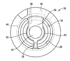
ここにおいて、仕切部材28は、図2〜4に示されている如き厚肉の略円板形状を有する仕切ブロック38を備えている。かかる仕切ブロック38には、その上端面と下端面の各中央部分において、上側中央凹所40と下側中央凹所42が、それぞれ略円形の凹陥形状をもって形成されている。
Here, the
また、仕切ブロック38には、外周面に開口して周方向に屈曲等して延びる周方向凹溝44が形成されており、この周方向凹溝44の両端部が軸方向各一方の面に開口せしめられている。更にまた、仕切ブロック38には、外周面に開口して軸方向に所定長さで直線的に延びる軸方向凹溝46が形成されており、この軸方向凹溝46の上端部が周方向凹溝44の一端部を利用して仕切部材28の上面に開口している一方、軸方向凹溝46の下端部がトンネル状で径方向に延びる連通孔48を通じて下側中央凹所42に接続されている。
In addition, the
さらに、仕切ブロック38の上側中央凹所40は、深さ方向中間部分に段差面50が設けられて、底部側の小径凹部52と開口側の大径凹部54からなる段付円形凹所とされている。また、段差面50には、幅方向の中間部分を周方向の全周に亘って連続して延びる略平面視円環形状の環状溝56が形成されている。
Further, the upper
更にまた、仕切ブロック38の下側中央凹所42の周りには、下側中央凹所42の外周壁部から仕切ブロック38の外周壁部に向かって延びる一対の径方向連結部58,58を残して、軸方向一方(図1中、下)に開口する略底面視円環形状の環状凹所60が形成されている。これにより、下側中央凹所42の周壁部が、実質的に一対の径方向連結部58,58のみによって仕切ブロック38の外周壁部と連結されている。なお、径方向連結部58の一方は、他方よりも幅広な形状とされていると共に、その内部に軸方向凹溝46と下側中央凹所42を相互に連通せしめる連通孔48が貫設されている。また、環状凹所60が環状溝56の底部に至る深さ寸法で形成されていることによって、環状溝56における径方向連結部58, 58の形成部位を除いた底部が、環状凹所60に開口されている。
Furthermore, a pair of radial connecting
また、小径凹部52の周壁部には、周方向に所定の長さで延びる連通窓62が貫設されている。特に本実施形態では、連通窓62が、周方向に略半周弱の長さで延びる長孔形状を呈していると共に、周方向に離隔して一対形成されている。これにより、小径凹部52が、一対の連通窓62,62を通じて環状凹所60と連通されている。また、仕切ブロック38が第二の取付金具14に嵌着固定された形態で、環状凹所60がゴムダイヤフラム30に面して開口されていることにより、仕切ブロック38における連通窓62や該連通窓62を通じて相互に連通せしめられた小径凹部52や環状凹所60が平衡室36の一部として構成されている。
Further, a
また、仕切ブロック38の大径凹部54に対して、可動仕切部材としての可動部材64が組み付けられていると共に、可動部材64の上方から、蓋板金具66が仕切ブロック38の上面に重ね合わされて組み付けられている。
In addition, a
可動部材64は、図5,6にも単品図が示されているように、円形の略薄板形状を有していると共に、ゴム弾性体により形成されている。そして、可動部材64が仕切ブロック38の大径凹部54に対して嵌着固定されていることにより、上側中央凹所40の開口が可動部材64によって流体密に覆蓋されており、以て、可動部材64の上方に受圧室34が形成されている一方、可動部材64の下方に平衡室36が形成されている。
The
また、可動部材64は、仕切ブロック38における段差面50の略内周縁部上に位置せしめられる部分において、周方向に連続して若しくは不連続に延びる環状の弾性突部68が一体形成されている。また、かかる弾性突部68における周上の適数箇所(本実施形態では、四箇所)には、更に大きく上下両面に突出する略台地形状の当接支持部70が一体形成されている。なお、本実施形態では、可動部材64における上下両方の弾性突部68,68の突出先端面間の寸法が、可動部材64の外周縁部の軸方向寸法よりも僅かに小さく設定されていると共に、上下両方の当接支持部70,70の突出先端面間の寸法が、可動部材64の外周縁部の軸方向寸法と略同じ大きさに設定されている。
Further, the
更にまた、可動部材64の中央部分には、金属や合成樹脂からなる硬質の拘束プレート72が埋設状態で固着されている。この拘束プレート72は、図7に示されているように、中央部分が僅かに凹んだ略浅皿形状とされており、薄肉ながら変形剛性の向上が図られている。また、拘束プレート72は、仕切ブロック38の上側中央凹所40の内径寸法よりも大きな外径寸法を有しており、拘束プレート72の外周縁部が、仕切ブロック38の段差面50にまで延び出している。
Furthermore, a
なお、拘束プレート72の外周縁部には、上下の当接支持部70,70に対応する複数箇所に、それぞれ切欠き74が設けられており、当接支持部70,70の形成部位を逃げるようにして拘束プレート72が可動部材64に被着されている。また、拘束プレート72の中心には、円形孔76が貫設されて可動部材64を構成するゴム材料によって覆蓋されている。この円形孔76が形成されていることにより、拘束プレート72の両面へのゴム材料の回りが良好とされて、ゴムの拘束プレート72に対する固着強度の向上も図られ得る。しかも、この円形孔76の大きさや、該円形孔76を閉塞するゴム膜の肉厚寸法を適当に調節することにより、可動部材64の弾性変形特性を適宜に調節することも出来る。尤も、この円形孔76は、必ずしも形成する必要はない。
さらに、可動部材64における弾性突部68と外周縁部の間に位置する部分には、薄肉の外周可動ゴム膜部78が、所定幅で周方向に延びる円環板形状をもって形成されている。そして、この外周可動ゴム膜部78が、仕切ブロック38の段差面50に形成された環状溝56上に位置せしめられている。
Furthermore, a thin outer peripheral movable
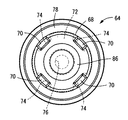
一方、蓋板金具66は、図8にも示されているように、全体として薄肉の略円板形状を有しており、径方向中間部分に僅かな段差部80が形成されて、外周縁部に対して中央部分が下方に突出せしめられている。そして、蓋板金具66は、仕切ブロック38の上面に重ね合わされて、段差部80が、仕切ブロック38の上側中央凹所40の開口部に嵌め込まれることにより、径方向に位置決めされて組み付けられている。
On the other hand, as shown in FIG. 8, the cover plate metal fitting 66 has a thin and substantially disk shape as a whole, and a slight stepped
また、蓋板金具66には、中央部分に円形の中央透孔82が貫設されていると共に、該中央透孔82の回りには、所定幅で周方向に延びる複数の外周透孔84が貫設されている。そして、蓋板金具66が仕切ブロック38に組み付けられた際、中央透孔82を通じて、拘束プレート72で補強された可動部材64の中央可動板部86が受圧室34に臨むようになっていると共に、外周透孔84を通じて、外周可動ゴム膜部78が受圧室34に臨むようになっている。また、外周可動ゴム膜部78は、仕切ブロック38の環状溝56を通じて平衡室36に臨むようになっている。
In addition, a circular central through
更にまた、蓋板金具66の外周縁部には、周上の一箇所に切欠き窓88が設けられており、この切欠き窓88が仕切ブロック38に設けられた周方向凹溝44と軸方向凹溝46の共通する上側開口部に位置合わせされている。なお、切欠き窓88と凹溝44,46の上側開口部を相互に位置合わせするために、仕切ブロック38の上端面には周上の適当な部位に位置決め突起90が突設されていると共に、蓋板金具66の対応する部位に位置決め孔92が形成されており、それら位置決め突起90と位置決め孔92の係合作用で周方向の位置決めが実現されるようになっている。
Furthermore, a
而して、上述の如き可動部材64および蓋板金具66の仕切ブロック38への組み付け状態下、可動部材64の各当接支持部70は、図9に拡大して示されているように、各先端面が、仕切ブロック38の段差面50または蓋板金具66の下面に対して当接されており、必要に応じて適当に圧縮されている。また、可動部材64の外周縁部が、軸方向寸法の大きくされた弾性嵌着部94とされており、かかる仕切ブロック38への組み付けに際して、該弾性嵌着部94が仕切ブロック38の段差面50と蓋板金具66の間において仕切ブロック38と蓋板金具66が接近する方向に圧縮変形されて挟圧配置されている。それによって、仕切ブロック38における上側中央凹所40の開口部が流体密に覆蓋されている。
Thus, under the assembled state of the
また、弾性突部68は、図10に拡大して示されているように、仕切ブロック38の段差面50または蓋板金具66の下面に対して僅かな隙間をもって位置せしめられている。そして、可動部材64に対して受圧室34の圧力変動が及ぼされた際には、可動部材64の上下面に及ぼされる受圧室34と平衡室36の圧力差に基づいて、可動部材64の変位乃至は変形が生ぜしめられるようになっている。
Further, as shown in an enlarged view in FIG. 10, the
ここにおいて、可動部材64における中央可動板部86は、埋設固着せしめられた拘束プレート72によってその変形が規制されており、主として当接支持部70,70の弾性変形に基づいて許容される変位が生ぜしめられるようになっている。一方、外周可動ゴム膜部78は、薄肉とされて、蓋板金具66の外周透孔84を通じて連通された受圧室34と仕切ブロック38の環状溝56を通じて連通された平衡室36の圧力差に基づいて、弾性変形が容易に生ぜしめられるようになっており、変形による変位が生ぜしめられるようになっている。
Here, the deformation of the central
また、仕切ブロック38の外周面に形成された周方向凹溝44および軸方向凹溝46の開口部は、何れも、第二の取付金具14で流体密に覆蓋されている。そして、周方向凹溝44が覆蓋されることにより、受圧室34と平衡室36を相互に連通する第一のオリフィス通路96が、常時、連通せしめられた状態で形成されている。また、軸方向凹溝46が覆蓋されることにより、仕切ブロック38の連通孔48から下側中央凹所42を通じて平衡室36に開口せしめられて、該平衡室36を受圧室34に連通せしめる第二のオリフィス通路98が形成されている。
The openings of the
この第二のオリフィス通路98は、第一のオリフィス通路96に比して略同じ通路断面積と短い通路長さで形成されている。これにより、第一のオリフィス通路96よりも第二のオリフィス通路98の方が高周波数域にチューニングされている。具体的には、第一のオリフィス通路96を通じて流動せしめられる流体の共振周波数が、該流体の共振作用に基づき、例えば±0.1mm程度で10Hz前後のエンジンシェイク等の低周波小振幅振動および±1.0mm程度で10Hz前後のエンジンシェイク等の低周波大振幅振動に対して高減衰特性が発揮されるようにチューニングされている。また、第二のオリフィス通路98を通じて流動せしめられる流体の共振周波数が、該流体の共振作用に基づき、例えば±0.1〜0.25mm程度で20〜40Hzのアイドリング振動等の中周波中振幅振動に対して低動ばね効果が発揮されるようにチューニングされている。更に、可動部材64の固有振動数が、該可動部材64の変位乃至は変形に基づき、例えば±0.01〜0.02mm程度で60〜120Hzの走行こもり音等の高周波微小振幅振動に対して可動部材64に共振現象が有効に生ぜしめられるようにチューニングされている。
The
そして、上述のように、第一の取付金具12と第二の取付金具14を有する本体ゴム弾性体16の一体加硫成形品に対して仕切部材28とゴムダイヤフラム30を組み付けて構成されたマウント本体には、更に、ブラケット18が組み付けられている。かかるブラケット18は、全体として大径で深底の略有底円筒形状を有しており、第二の取付金具14に対して外嵌固定されている。また、ブラケット18が、大径の略円筒形状を有する固着筒金具100に圧入固定されており、該固着筒金具100が自動車用ボデーにボルト固定されることにより、第二の取付金具14が、ブラケット18を介して、自動車用ボデーに取り付けられるようになっている。
As described above, the mount configured by assembling the
また、ブラケット18は、第二の取付金具14に対して十分に深底とされており、第二の取付金具14が嵌着固定された状態下、ブラケット18の底部には十分な大きさの内部空所102が形成されている。そして、この内部空所102によって、ゴムダイヤフラム30の膨出変形が十分に大きく許容されるようになっている。
The
さらに、ブラケット18の底部には、空気圧式アクチュエータ104が装備されている。この空気圧式アクチュエータ104は、ブラケット18の底部をベースハウジング106に利用しており、かかるベースハウジング106に対して、弁手段としての出力部材108がブラケット18の内部に位置するようにして組み付けられている。
Further, a
かかる出力部材108は、全体として略ハット形状を有する仕切ゴム110を備えており、該仕切ゴム110の中央部分が逆カップ形状の出力部112とされていると共に、その外周部分が、該出力部112の下端開口周縁部から斜め下方に広がるテーパ付き鍔状の弾性周壁部114とされている。また、出力部112には、金属や合成樹脂で形成された硬質の補強部材116が埋設固着されている一方、弾性周壁部114の外周縁部には、環状の圧入金具118が加硫接着されている。
The
そして、圧入金具118がブラケット18の底部周壁に対して圧入固定されることにより、仕切ゴム110の外周縁部がブラケット18で形成されたベースハウジング106の底面に対して流体密に当接されている。これにより、出力部材108の開口がベースハウジング106の底壁部で覆蓋されて内部に調圧空気室120が形成された空気圧式アクチュエータ104が構成されている。
Then, the press-fitting metal fitting 118 is press-fitted and fixed to the bottom peripheral wall of the
なお、本実施形態では、調圧空気室120に圧縮コイルスプリング122が収容されて組み付けられていることにより、出力部112とベースハウジング106の間に離隔方向の付勢力が常時及ぼされるようになっている。また、ベースハウジング106の底部中央を貫通してエアポート124が設けられている。そして、このエアポート124を通じて、外部から、調圧空気室120の圧力を制御することが出来るようになっている。
In the present embodiment, the
すなわち、防振マウント10の装着状態下において、このエアポート124に対して外部の空気圧管路126が接続されており、かかる空気圧管路126を通じて切換弁128が接続されている。そして、切換弁128の切り換え作動に従って、調圧空気室120に大気中と負圧源130が選択的に接続されるようになっている。
In other words, an external
そして、調圧空気室120が大気中に接続された状態下では、弾性周壁部114の弾性と、圧縮コイルスプリング122の弾性が出力部112に作用することにより、出力部112が上方に弾性的に突出せしめられて、ゴムダイヤフラム30を上方に付勢せしめて、仕切部材28における仕切ブロック38の中央下面に対して押し付けた状態に保持されるようになっている。ここにおいて、出力部112の外形は、仕切ブロック38の中央下面に形成された下側中央凹所42の開口径よりも大きなものとされていることから、ゴムダイヤフラム30の中央部を下側中央凹所42の開口部に押し付けて、実質的に流体密に覆蓋することとなり、これによって、下側中央凹所42を通じて平衡室36に開口せしめられる第二のオリフィス通路98を遮断するようになっている。
In a state where the
一方、調圧空気室120が負圧源130に接続された状態下では、弾性周壁部114の弾性と圧縮コイルスプリング122の弾性に抗して、該調圧空気室120内に及ぼされる負圧と外部大気圧との圧力差に基づいて出力部112が調圧空気室120の内方に吸引され、軸方向下方に変位せしめられることとなる。それ故、ゴムダイヤフラム30が下側中央凹所42の開口部から離隔せしめられて、第二のオリフィス通路98が開口、連通状態とされる。
On the other hand, under the state in which the
ここにおいて、本実施形態では、切換弁128が制御装置132により、自動車の走行状態と、停車状態によって切り換えられるようになっている。すなわち、走行状態下では、調圧空気室120が大気中に接続される一方、停車状態下では、調圧空気室120が負圧源130に接続されるようになっている。なお、かかる制御装置132としては、例えば、加速度センサ等によって、切換弁128を構成する電磁ソレノイドに駆動制御信号を出力することによって有利に構成される。
Here, in this embodiment, the switching
従って、上述の如き構造とされた防振マウント10では、その走行時の段差の乗り越え等において入力される低周波大振幅振動に対して、中央可動板部86と外周可動ゴム膜部78からなる可動部材64の変位乃至は変形による液圧吸収が追従し得ずに受圧室34には有効な圧力変動が惹起され得ることとなる。これにより、受圧室34と平衡室36の間に相対的な圧力変動が有効に生ぜしめられる。それ故、第二のオリフィス通路98を出力部材108で遮断状態に維持すれば、第一のオリフィス通路96を通じての流体流動量が有利に確保され得て、該第一のオリフィス通路96を通じて流動せしめられる流体の共振作用等の流動作用に基づく高減衰効果が発揮され、優れた防振性能が実現され得ることとなる。
Therefore, the
また、その通常走行状態下において入力される低周波小振幅振動に対しては、上述の低周波大振幅振動の場合と同様に、第二のオリフィス通路98を出力部材108で遮断状態に維持すれば、第一のオリフィス通路96を通じての流体流動量が有利に確保され得て、該第一のオリフィス通路96を流動せしめられる流体の共振作用等の流動作用に基づく高減衰効果が発揮され、優れた防振性能が実現され得ることとなる。なお、可動部材64による受圧室34の圧力吸収が懸念されるが、本実施形態では、中央可動板部86の外周側における流体密性が外周可動ゴム膜部78によって確保されていることと、中央可動板部86が硬質とされて可動部材64の変形量が抑えられるようになっていることから、受圧室34には未だ十分に有効な圧力変動が惹起されることとなる。
Further, for the low frequency small amplitude vibration input in the normal running state, the
さらに、走行時に入力される高周波微小振幅振動に対しては、受圧室34の圧力変動が非常に小さいことから、可動部材64の変位乃至は変形によって受圧室34の圧力変動が有効に吸収乃至は軽減され得る。特に、可動部材64の中央可動板部86は、中央部分に形成されて有効面積を有利に確保することが出来ると共に、その外周縁部を流体密に支持せしめる外周可動ゴム膜部78が変形容易とされていることから、受圧室34における高周波数域の圧力変動に対して有利に追従変位し得て、受圧室34の圧力変動を抑えることが出来るのである。
Further, since the pressure fluctuation in the
しかも、可動部材64の固有振動数が防振すべき振動の高周波数域にチューニングされていることから、かかる高周波振動が入力された際に、可動部材64が共振作用に基づいて一層有利に追従変位される。それ故、当該高周波数域の振動入力時には、第一及び第二のオリフィス通路96,98が実質的に閉塞状態となった状態下においても、受圧室34の著しい圧力変動が可動部材64によって回避され得て、低動ばね特性に基づく有効な振動絶縁作用により優れた防振性能が発揮され得ることとなる。
In addition, since the natural frequency of the
更にまた、停車時に入力される中周波中振幅振動に対しては、可動部材64による受圧室34の圧力吸収が懸念されるが、本実施形態では、硬質の中央可動板部86が可動部材64の中央部分に設けられていることに基づいて可動部材64の変形量が抑えられるようになっていると共に、中央可動板部86の外周側に外周可動ゴム膜部78が設けられて受圧室34の流体密性が確保されていることに基づいて受圧室34から平衡室36への圧力漏れが回避されるようなっていることから、受圧室34には未だ十分に圧力変動が惹起されることとなる。それ故、空気圧式アクチュエータ104を作動せしめて第二のオリフィス通路98を連通状態とすることによって、第二のオリフィス通路98を通じての流体流動量が十分に確保され得て、該第二のオリフィス通路98を流動せしめられる流体の共振作用等の流動作用に基づく高減衰効果が発揮されて、優れた防振性能が発揮され得る。なお、第二のオリフィス通路98の連通状態下では、第一のオリフィス通路96も連通状態にあるが、第一のオリフィス通路96のチューニング周波数を超えた周波数域となる中周波の入力振動に対しては、第一のオリフィス通路96を通じての流体の反共振的な作用に起因して第一のオリフィス通路96が実質的に閉塞された状態とされることから、当該第二のオリフィス通路98を通じての流体流動量が有効に確保されることとなる。
Furthermore, although there is a concern about the pressure absorption of the
従って、本実施形態に係る防振マウント10においては、防振すべき振動の周波数や振幅に応じて、第一のオリフィス通路96や第二のオリフィス通路98、可動部材64が、それぞれ、効率的に機能されることによって、複数の乃至は広い周波数域の振動に対して優れた防振効果が発揮され得る。
Therefore, in the
そこにおいて、本実施形態では、中央可動板部86と外周可動ゴム膜部78からなる可動部材64が採用されていることによって、可動部材64による受圧室34の液圧吸収を抑えて受圧室34に圧力変動を有効に惹起させる形態が要求される、例えば上述の低周波小振幅振動や中周波中振幅振動等の入力時に、可動部材64の中央に硬質の中央可動板部86が形成されて可動部材64の変形量が抑えられていることと、中央可動板部86の外周側の流体密性が外周可動ゴム膜部78で確保されていることに基づいて、受圧室34に有効な圧力変動が惹起される。それ故、第一のオリフィス通路96または第二のオリフィス通路98を通じての各流体流動量が十分に確保されることから、第二のオリフィス通路98を遮断状態と連通状態に選択的に切り換え作動せしめることによって、各オリフィス通路96,98を通じての流体流動作用に基づく防振効果が有利に発揮され得る。
Therefore, in the present embodiment, the
その結果、例えば特開2002−5225号公報等に示されているように、可動部材を挟んで受圧室と反対側に空気室を形成し、該空気室に外部から空気圧(負圧または正圧)を及ぼして可動部材を拘束変形させて、その液圧吸収作用を抑える構造等を特別に採用しなくとも、本実施形態に係る可動部材64の構造によって変形乃至は変位量が抑えられて受圧室34に圧力変動が有効に惹起されることから、仕切部材28を含む内部構造の簡略化に伴い、第一のオリフィス通路96や第二のオリフィス通路98、可動部材64の配設スペース等の設計自由度が大きく確保されることによって、目的とする防振効果が安定して得られるのである。
As a result, as shown in, for example, Japanese Patent Application Laid-Open No. 2002-5225, an air chamber is formed on the opposite side of the pressure receiving chamber across the movable member, and air pressure (negative pressure or positive pressure) is externally applied to the air chamber. ), The movable member is restrained and deformed, and the structure of the
加えて、上述の特開2002−5225号公報等を含む従来構造の防振マウントに比して、仕切部材に空気室や該空気室に外部から空気圧を及ぼすための空気通路を形成したり、第二の取付金具にエアポートを配設したり等する必要がないことから、製造が容易とされると共に、受圧室34や平衡室36の流体密性が好適に確保され得るのである。
In addition, as compared with the conventional anti-vibration mount including the above-mentioned Japanese Patent Application Laid-Open No. 2002-5225, etc., an air passage for applying air pressure from the outside to the air chamber or the air chamber is formed in the partition member, Since it is not necessary to provide an air port or the like on the second mounting bracket, manufacturing is facilitated, and fluid tightness of the
また、本実施形態では、要求される受圧室34の流体密性が確保される限りにおいて、受圧室34の流体が可動部材64の外方に多少の漏れが生じる場合にあっても、可動部材64を挟んで受圧室34と反対側が平衡室36とされていることにより、流体の非封入領域外への漏れ出しが問題となることもないことから、品質性能の向上が図られ得る。
Further, in the present embodiment, as long as the required fluid tightness of the
さらに、本実施形態では、可動部材64に弾性当接突部としての弾性突部68および当接支持部70を突出形成することによって、可動部材64の変位量を制限して、低周波小振幅振動の入力時の可動部材64による圧力吸収を一層効果的に抑えることができる。
Furthermore, in the present embodiment, the amount of displacement of the
更にまた、本実施形態の防振マウント10では、可動部材64の中央可動板部86に拘束プレート72が埋設状態で固設されていることから、中央可動板部86における不必要な変形に起因する低〜中周波数域の振動入力時における受圧室34の圧力変動の吸収が一層確実に抑えられ得ることとなり、第一のオリフィス通路96や第二のオリフィス通路98における流体流動による防振効果が効果的に発揮される。
Furthermore, in the
以上、本発明の実施形態について詳述してきたが、これはあくまでも例示であり、かかる実施形態における具体的な記載によって、本発明は、何等限定されるものでなく、当業者の知識に基づいて種々なる変更、修正、改良等を加えた態様で実施可能であり、また、そのような実施態様が、本発明の趣旨を逸脱しない限り、何れも、本発明の範囲内に含まれるものであることは、言うまでもない。 The embodiment of the present invention has been described in detail above, but this is merely an example, and the present invention is not limited to a specific description in the embodiment, and is based on the knowledge of those skilled in the art. The present invention can be implemented with various changes, modifications, improvements, and the like, and any such embodiments are included in the scope of the present invention without departing from the spirit of the present invention. Needless to say.
例えば、前記実施形態において、平衡室36の一部を構成する小径凹部52や連通窓62、環状凹所60の形状や大きさ、構造等を適宜に設定変更して、仕切ブロック38内における平衡室36の一部を流体流路として機能させると共に、流体流路を通じて流動せしめられる流体の共振周波数を、例えば±0.03mm程度で80Hz前後の高周波微小振幅振動の周波数域等にチューニングすることも可能である。
For example, in the above-described embodiment, the shape, size, structure, and the like of the small-
また、前記実施形態においては、硬質の拘束プレート72を埋設することによって、中央可動板部86を補強しているが、この拘束プレート72は無くても良い。即ち、可動部材64を、例えば必要に応じて厚肉化することによって、十分に硬質とすることで、拘束プレート72等によって補強することなく中央可動板部86としての機能を発揮させることも可能である。
Further, in the embodiment, the central
また、前記実施形態では、下側中央凹所42の開口部に押圧するための付勢手段として圧縮コイルスプリング122を用いていたが、付勢手段は、前記実施形態のものに限定されるものではない。具体的には、例えば、仕切ゴム110の弾性だけを利用して、当接状態に保持せしめることも可能であり、或いは、圧縮コイルスプリング122に代えて板バネ等を用いることも可能である
Moreover, in the said embodiment, although the
また、可動部材64における中央可動板部86や外周可動ゴム膜部78の形状や大きさ、構造、更には可動部材64の仕切部材28に対する配設位置等は、例示の如きものに限定されるものでなく、要求される防振特性や製作性等に応じて、適宜に設定変更され得る。
In addition, the shape, size, and structure of the central
また、仕切部材28に形成されるオリフィス通路の形状や大きさ、構造、数等は、前記実施形態に示された第一及び第二のオリフィス通路96,98に限定されるものでなく、当業者が適宜に設定変更し得る事項の一つである。
Further, the shape, size, structure, number, and the like of the orifice passage formed in the
加えて、前記実施形態では、本発明を自動車用のエンジンマウントに適用したものの具体例を示したが、その他、本発明は、自動車以外のエンジンマウント装置に対しても、有利に適用され得るものであることは勿論である。 In addition, in the said embodiment, although the specific example of what applied this invention to the engine mount for motor vehicles was shown, other than this, this invention can be applied advantageously also to engine mount apparatuses other than a motor vehicle. Of course.
10 防振マウント
12 第一の取付金具
14 第二の取付金具
16 本体ゴム弾性体
34 受圧室
36 平衡室
64 可動部材
78 外周可動ゴム膜部
86 中央可動板部
96 第一のオリフィス通路
98 第二のオリフィス通路
104 空気圧式アクチュエータ
108 出力部材
DESCRIPTION OF
Claims (7)
それらパワーユニット側部材と車両ボデー側部材の他方に取り付けられる第二の取付部材と、
前記第一の取付部材と前記第二の取付部材を弾性的に連結する本体ゴム弾性体と、
該本体ゴム弾性体によって壁部の一部が構成されて振動が入力される、非圧縮性流体が封入された受圧室と、
壁部の一部が可撓性膜で構成されて容積変化が容易に許容される、非圧縮性流体が封入された平衡室と、
前記受圧室と前記平衡室を相互に連通せしめる、エンジンシェイクに略相当する低周波数域にチューニングされた第一のオリフィス通路と、
前記受圧室と前記平衡室を相互に連通せしめる、アイドリング振動に略相当する中周波数域にチューニングされた第二のオリフィス通路と、
該第二のオリフィス通路を連通/遮断する弁手段と、
外部から及ぼされる空気圧で作動せしめられて前記弁手段を駆動する空気圧式アクチュエータと、
中央部分が硬質の中央可動板部とされていると共に外周部分が変形容易な外周可動ゴム膜部とされており、該外周可動ゴム膜部の外周縁部において前記第二の取付部材で実質的に流体密に支持されて前記受圧室と前記平衡室を仕切るようにして配設せしめられ、その一方の面側に形成された該受圧室と他方の面側に形成された該平衡室との圧力差に基づいて該中央可動板部および該外周可動ゴム膜部の変位乃至は変形が許容されるように配設されて、かかる変位乃至は変形によって走行こもり音に略相当する高周波数域の振動入力時における該受圧室の圧力変動を吸収する可動仕切部材と
を、有しており、且つ、
前記平衡室の一部を狭窄せしめて流体流路を形成して、前記可動仕切部材の両面に及ぼされる前記受圧室と前記平衡室の圧力差に基づく該可動仕切部材の変位乃至は変形に基づいて該流体流路を通じての実質的な流体流動が許容されるようにしたことを特徴とする空気圧切換型の流体封入式エンジンマウント。 A first attachment member attached to one of the power unit side member and the vehicle body side member;
A second attachment member attached to the other of the power unit side member and the vehicle body side member;
A main rubber elastic body for elastically connecting the first mounting member and the second mounting member;
A pressure receiving chamber in which an incompressible fluid is sealed, in which a vibration is input by forming a part of the wall portion by the main rubber elastic body;
An equilibrium chamber in which an incompressible fluid is sealed, in which a part of the wall portion is formed of a flexible film and volume change is easily allowed;
A first orifice passage tuned to a low frequency region substantially corresponding to an engine shake, which allows the pressure receiving chamber and the equilibrium chamber to communicate with each other;
A second orifice passage tuned to an intermediate frequency range substantially corresponding to idling vibration, which allows the pressure receiving chamber and the equilibrium chamber to communicate with each other;
Valve means for communicating / blocking the second orifice passage;
A pneumatic actuator that is actuated by air pressure exerted from outside to drive the valve means;
The central portion is a rigid central movable plate portion, and the outer peripheral portion is an outer peripheral movable rubber film portion that is easily deformable. The outer peripheral edge of the outer peripheral movable rubber film portion is substantially the same as the second mounting member. The pressure receiving chamber and the equilibrium chamber are arranged so as to partition the pressure receiving chamber and the equilibrium chamber, and the pressure receiving chamber formed on one surface side of the pressure receiving chamber and the equilibrium chamber formed on the other surface side are arranged. The central movable plate portion and the outer peripheral movable rubber film portion are disposed so as to be allowed to be displaced or deformed based on the pressure difference, and the displacement or deformation causes a high frequency range substantially corresponding to a traveling boom sound. a movable partition member which absorbs pressure fluctuations in the receiving chamber during input of vibration, and possess, and,
Based on the displacement or deformation of the movable partition member based on the pressure difference between the pressure receiving chamber and the equilibrium chamber exerted on both surfaces of the movable partition member by forming a fluid flow path by constricting a part of the equilibrium chamber. A pneumatically switched fluid-filled engine mount characterized in that substantial fluid flow is allowed through the fluid flow path .
それらパワーユニット側部材と車両ボデー側部材の他方に取り付けられる第二の取付部材と、 A second attachment member attached to the other of the power unit side member and the vehicle body side member;
前記第一の取付部材と前記第二の取付部材を弾性的に連結する本体ゴム弾性体と、 A main rubber elastic body for elastically connecting the first mounting member and the second mounting member;
該本体ゴム弾性体によって壁部の一部が構成されて振動が入力される、非圧縮性流体が封入された受圧室と、 A pressure receiving chamber in which an incompressible fluid is sealed, in which a vibration is input by forming a part of the wall portion by the main rubber elastic body;
壁部の一部が可撓性膜で構成されて容積変化が容易に許容される、非圧縮性流体が封入された平衡室と、 An equilibrium chamber in which an incompressible fluid is sealed, in which a part of the wall portion is formed of a flexible film and volume change is easily allowed;
前記受圧室と前記平衡室を相互に連通せしめる、エンジンシェイクに略相当する低周波数域にチューニングされた第一のオリフィス通路と、 A first orifice passage tuned to a low frequency region substantially corresponding to an engine shake, which allows the pressure receiving chamber and the equilibrium chamber to communicate with each other;
前記受圧室と前記平衡室を相互に連通せしめる、アイドリング振動に略相当する中周波数域にチューニングされた第二のオリフィス通路と、 A second orifice passage tuned to an intermediate frequency range substantially corresponding to idling vibration, which allows the pressure receiving chamber and the equilibrium chamber to communicate with each other;
該第二のオリフィス通路を連通/遮断する弁手段と、 Valve means for communicating / blocking the second orifice passage;
外部から及ぼされる空気圧で作動せしめられて前記弁手段を駆動する空気圧式アクチュエータと、 A pneumatic actuator that is actuated by air pressure exerted from outside to drive the valve means;
中央部分が硬質の中央可動板部とされていると共に外周部分が変形容易な外周可動ゴム膜部とされており、該外周可動ゴム膜部の外周縁部において前記第二の取付部材で実質的に流体密に支持されて前記受圧室と前記平衡室を仕切るようにして配設せしめられ、その一方の面側に形成された該受圧室と他方の面側に形成された該平衡室との圧力差に基づいて該中央可動板部および該外周可動ゴム膜部の変位乃至は変形が許容されるように配設されて、かかる変位乃至は変形によって走行こもり音に略相当する高周波数域の振動入力時における該受圧室の圧力変動を吸収する可動仕切部材と The central portion is a rigid central movable plate portion, and the outer peripheral portion is an outer peripheral movable rubber film portion that is easily deformable. The outer peripheral edge of the outer peripheral movable rubber film portion is substantially the same as the second mounting member. The pressure receiving chamber and the equilibrium chamber are arranged so as to partition the pressure receiving chamber and the equilibrium chamber, and the pressure receiving chamber formed on one surface side of the pressure receiving chamber and the equilibrium chamber formed on the other surface side are arranged. The central movable plate portion and the outer peripheral movable rubber film portion are disposed so as to be allowed to be displaced or deformed based on the pressure difference, and the displacement or deformation causes a high frequency range substantially corresponding to a traveling noise. A movable partition member that absorbs pressure fluctuations in the pressure receiving chamber during vibration input;
を、有しており、且つ、And
前記可動仕切部材における前記中央可動板部に硬質の拘束プレートを配設し、該拘束プレートの外周縁部に対して前記外周可動ゴム膜部を接着せしめる一方、 While disposing a hard restraint plate on the central movable plate part in the movable partition member, and adhering the outer peripheral movable rubber film part to the outer peripheral edge part of the restraint plate,
前記可動仕切部材における前記拘束プレートが配設された前記中央可動板部の外周部分の複数箇所において板厚方向の両側に突出する弾性当接突部を形成し、前記第二の取付部材又は該第二の取付部材によって支持せしめた変位規制部材に対して該弾性当接突部を離隔して対向位置せしめて、該弾性当接突部の該変位規制部材への当接によって該中央可動板部の変位量を緩衝的に制限する変位量制限手段を設けると共に、 Elastic contact protrusions that protrude on both sides in the plate thickness direction are formed at a plurality of locations on the outer peripheral portion of the central movable plate portion on which the restraint plate is disposed in the movable partition member, and the second mounting member or the The elastic contact protrusion is spaced apart from the displacement restricting member supported by the second mounting member, and the central movable plate is brought into contact with the displacement restricting member by contacting the elastic contact protrusion. Displacement amount limiting means for buffering the amount of displacement of the part is provided, and
前記中央可動板部の外周部分の複数箇所において前記弾性当接突部と一体的に形成されて該弾性当接突部より大きな突出高さで板厚方向の両側に突出する当接支持部を設けて、該当接支持部を前記変位規制部材に対して当接状態として該当接支持部によって該中央可動板部の該拘束プレートを弾性的に支持せしめた Contact support portions that are integrally formed with the elastic contact protrusions at a plurality of locations on the outer peripheral portion of the central movable plate portion and protrude to both sides in the plate thickness direction with a protrusion height larger than the elastic contact protrusions. And the constraining plate of the central movable plate part is elastically supported by the corresponding contact support part with the corresponding contact support part in contact with the displacement regulating member.
ことを特徴とする空気圧切換型の流体封入式エンジンマウント。A fluid-filled engine mount with pneumatic switching.
Priority Applications (3)
| Application Number | Priority Date | Filing Date | Title |
|---|---|---|---|
| JP2004160332A JP4158111B2 (en) | 2004-05-28 | 2004-05-28 | Pneumatic switching type fluid-filled engine mount |
| US11/132,410 US7416173B2 (en) | 2004-05-24 | 2005-05-19 | Pneumatically switchable type fluid-filled engine mount |
| GB0510341A GB2414533B (en) | 2004-05-24 | 2005-05-20 | Pneumatically switchable type fluid-filled engine mount |
Applications Claiming Priority (1)
| Application Number | Priority Date | Filing Date | Title |
|---|---|---|---|
| JP2004160332A JP4158111B2 (en) | 2004-05-28 | 2004-05-28 | Pneumatic switching type fluid-filled engine mount |
Publications (2)
| Publication Number | Publication Date |
|---|---|
| JP2005337463A JP2005337463A (en) | 2005-12-08 |
| JP4158111B2 true JP4158111B2 (en) | 2008-10-01 |
Family
ID=35491249
Family Applications (1)
| Application Number | Title | Priority Date | Filing Date |
|---|---|---|---|
| JP2004160332A Expired - Fee Related JP4158111B2 (en) | 2004-05-24 | 2004-05-28 | Pneumatic switching type fluid-filled engine mount |
Country Status (1)
| Country | Link |
|---|---|
| JP (1) | JP4158111B2 (en) |
Families Citing this family (4)
| Publication number | Priority date | Publication date | Assignee | Title |
|---|---|---|---|---|
| JP5060846B2 (en) * | 2007-06-29 | 2012-10-31 | 東海ゴム工業株式会社 | Fluid filled vibration isolator |
| JP5085502B2 (en) * | 2008-10-14 | 2012-11-28 | 東海ゴム工業株式会社 | Plastic cylindrical bracket and anti-vibration mount assembly using such plastic cylindrical bracket |
| KR101551947B1 (en) | 2010-07-07 | 2015-09-10 | 현대자동차주식회사 | Hydraulic engine mount for automobile |
| JP6071682B2 (en) * | 2013-03-25 | 2017-02-01 | 株式会社ブリヂストン | Vibration isolator |
-
2004
- 2004-05-28 JP JP2004160332A patent/JP4158111B2/en not_active Expired - Fee Related
Also Published As
| Publication number | Publication date |
|---|---|
| JP2005337463A (en) | 2005-12-08 |
Similar Documents
| Publication | Publication Date | Title |
|---|---|---|
| JP4120828B2 (en) | Fluid filled active vibration isolator | |
| JP5095763B2 (en) | Liquid-filled vibration isolator | |
| WO2010032344A1 (en) | Liquid-sealed type vibration isolator | |
| JPH04277338A (en) | Liquid-filled type mount device | |
| JP5977141B2 (en) | Fluid filled vibration isolator | |
| JP2008101719A (en) | Fluid sealed vibration absorbing device | |
| JP5325602B2 (en) | Fluid filled vibration isolator | |
| JP2009243510A (en) | Fluid-filled type engine mount for automobile | |
| JP5431982B2 (en) | Liquid-filled vibration isolator | |
| JP4016869B2 (en) | Fluid filled engine mount | |
| JP4158110B2 (en) | Pneumatic switching type fluid-filled engine mount | |
| JP5530816B2 (en) | Fluid filled vibration isolator | |
| JP2003139189A (en) | Fluid sealing type vibration isolation device | |
| JP5184272B2 (en) | Liquid-filled vibration isolator | |
| JP4158111B2 (en) | Pneumatic switching type fluid-filled engine mount | |
| JPH1089402A (en) | Liquid sealed-type mount equipment | |
| JP4158108B2 (en) | Pneumatic switching type fluid-filled engine mount | |
| JP2004069005A (en) | Fluid-sealed type vibration damper | |
| JP2008121811A (en) | Fluid-sealed vibration isolator | |
| JP4075066B2 (en) | Fluid filled engine mount | |
| JP4269952B2 (en) | Fluid filled vibration isolator | |
| JP4623428B2 (en) | Fluid filled vibration isolator | |
| JP3994397B2 (en) | Fluid filled vibration isolator | |
| JP4210851B2 (en) | Fluid-filled engine mount for vehicles | |
| JPH11101294A (en) | Fluid-filled mount device |
Legal Events
| Date | Code | Title | Description |
|---|---|---|---|
| A621 | Written request for application examination |
Free format text: JAPANESE INTERMEDIATE CODE: A621 Effective date: 20060823 |
|
| A977 | Report on retrieval |
Free format text: JAPANESE INTERMEDIATE CODE: A971007 Effective date: 20070704 |
|
| A131 | Notification of reasons for refusal |
Free format text: JAPANESE INTERMEDIATE CODE: A131 Effective date: 20070706 |
|
| A521 | Request for written amendment filed |
Free format text: JAPANESE INTERMEDIATE CODE: A523 Effective date: 20070903 |
|
| TRDD | Decision of grant or rejection written | ||
| A01 | Written decision to grant a patent or to grant a registration (utility model) |
Free format text: JAPANESE INTERMEDIATE CODE: A01 Effective date: 20080619 |
|
| A01 | Written decision to grant a patent or to grant a registration (utility model) |
Free format text: JAPANESE INTERMEDIATE CODE: A01 |
|
| A61 | First payment of annual fees (during grant procedure) |
Free format text: JAPANESE INTERMEDIATE CODE: A61 Effective date: 20080702 |
|
| R150 | Certificate of patent or registration of utility model |
Free format text: JAPANESE INTERMEDIATE CODE: R150 Ref document number: 4158111 Country of ref document: JP Free format text: JAPANESE INTERMEDIATE CODE: R150 |
|
| FPAY | Renewal fee payment (event date is renewal date of database) |
Free format text: PAYMENT UNTIL: 20110725 Year of fee payment: 3 |
|
| FPAY | Renewal fee payment (event date is renewal date of database) |
Free format text: PAYMENT UNTIL: 20120725 Year of fee payment: 4 |
|
| FPAY | Renewal fee payment (event date is renewal date of database) |
Free format text: PAYMENT UNTIL: 20120725 Year of fee payment: 4 |
|
| FPAY | Renewal fee payment (event date is renewal date of database) |
Free format text: PAYMENT UNTIL: 20130725 Year of fee payment: 5 |
|
| LAPS | Cancellation because of no payment of annual fees |