JP4147632B2 - Image information conversion apparatus, image information conversion method, and television receiver - Google Patents
Image information conversion apparatus, image information conversion method, and television receiver Download PDFInfo
- Publication number
- JP4147632B2 JP4147632B2 JP23731398A JP23731398A JP4147632B2 JP 4147632 B2 JP4147632 B2 JP 4147632B2 JP 23731398 A JP23731398 A JP 23731398A JP 23731398 A JP23731398 A JP 23731398A JP 4147632 B2 JP4147632 B2 JP 4147632B2
- Authority
- JP
- Japan
- Prior art keywords
- class
- value
- image signal
- image data
- class value
- Prior art date
- Legal status (The legal status is an assumption and is not a legal conclusion. Google has not performed a legal analysis and makes no representation as to the accuracy of the status listed.)
- Expired - Fee Related
Links
Images


Classifications
-
- H—ELECTRICITY
- H04—ELECTRIC COMMUNICATION TECHNIQUE
- H04N—PICTORIAL COMMUNICATION, e.g. TELEVISION
- H04N7/00—Television systems
- H04N7/01—Conversion of standards, e.g. involving analogue television standards or digital television standards processed at pixel level
- H04N7/0135—Conversion of standards, e.g. involving analogue television standards or digital television standards processed at pixel level involving interpolation processes
- H04N7/0137—Conversion of standards, e.g. involving analogue television standards or digital television standards processed at pixel level involving interpolation processes dependent on presence/absence of motion, e.g. of motion zones
-
- H—ELECTRICITY
- H04—ELECTRIC COMMUNICATION TECHNIQUE
- H04N—PICTORIAL COMMUNICATION, e.g. TELEVISION
- H04N7/00—Television systems
- H04N7/01—Conversion of standards, e.g. involving analogue television standards or digital television standards processed at pixel level
- H04N7/0117—Conversion of standards, e.g. involving analogue television standards or digital television standards processed at pixel level involving conversion of the spatial resolution of the incoming video signal
- H04N7/012—Conversion between an interlaced and a progressive signal
-
- H—ELECTRICITY
- H04—ELECTRIC COMMUNICATION TECHNIQUE
- H04N—PICTORIAL COMMUNICATION, e.g. TELEVISION
- H04N7/00—Television systems
- H04N7/01—Conversion of standards, e.g. involving analogue television standards or digital television standards processed at pixel level
- H04N7/0125—Conversion of standards, e.g. involving analogue television standards or digital television standards processed at pixel level one of the standards being a high definition standard
-
- H—ELECTRICITY
- H04—ELECTRIC COMMUNICATION TECHNIQUE
- H04N—PICTORIAL COMMUNICATION, e.g. TELEVISION
- H04N7/00—Television systems
- H04N7/01—Conversion of standards, e.g. involving analogue television standards or digital television standards processed at pixel level
- H04N7/0135—Conversion of standards, e.g. involving analogue television standards or digital television standards processed at pixel level involving interpolation processes
Description
【0001】
【発明の属する技術分野】
この発明は、入力画像信号からより高い解像度を有する画像信号を生成する機能を有する画像情報変換装置、画像情報変換方法、およびテレビジョン受像機に関する。
【0002】
【従来の技術】
入力画像信号よりも解像度の高い画像信号を得る等の目的で、入力画像信号とは走査線構造が異なる出力画像信号を形成する画像情報変換処理が行われる。画像情報変換処理として、入力画像信号の信号レベルの3次元(時空間)分布に応じてクラス分割を行い、それによって得られるクラス値を参照して画素の予測生成を行う、クラス分類適応処理が提案されている。かかる処理において、入力画像信号の走査線に対応する位置において画素を予測生成する場合には、入力画像信号の走査線に対応しない位置において画素を予測生成する場合よりも、大きな困難さを伴う。
【0003】
このため、入力画像信号の走査線に対応しない位置についてより多くのクラス数を割当てることにより、かかる位置における画素の予測生成をよりきめ細かく行うようにすれば、特に、クラス分類に対応して保持される予測生成処理に係るデータを記憶するメモリの使用方法等の観点から、より効率的な処理が可能となる。
【0004】
一方、より多くのクラス数を用いる程、画像情報変換処理を行うために必要なメモリの記憶容量が増大する。従って、実際の装置において記憶容量が限られることを考慮すると、クラスの総数を削減することが必要となる。
【0005】
【発明が解決しようとする課題】
従って、この発明の目的は、画素が予測生成されるべき位置と入力画像信号の走査線との位置関係、装置内に設けられるメモリの記憶容量等の条件に応じて適切なクラス数を割当てることを可能とする画像情報変換装置、画像情報変換方法、およびテレビジョン受像機を提供することにある。
【0006】
【課題を解決するための手段】
請求項1の発明は、入力画像信号から走査線構造の異なる出力画像信号を形成するようにした画像情報変換装置において、
入力画像信号に存在する走査線上の第1の注目点と、入力画像信号に存在せず、生成される走査線上の第2の注目点とのそれぞれに時間的または空間的に近傍に位置する複数の画素を、入力画像信号から選択する第1の画像データ選択手段と、
第1の画像データ選択手段によって選択される画像データから、レベル分布のパターンを検出し、検出したパターンに基づいて第1および第2の注目点がそれぞれ属する第1のクラス値を決定するクラス検出手段と、
第1および第2の注目点のそれぞれの第1のクラス値に対して、予め学習によって生成されているクラス値変換テーブルを参照してクラス値変換処理を施して、第2のクラス値を生成するクラス値変換手段と、
入力画像信号から、第1および第2の注目点のそれぞれに時間的または空間的に近傍に位置する複数の画素を選択する第2の画像データ選択手段と、
第2の画像データ選択手段によって選択された画像データ、および第2のクラス値に対応して指定される第1の予測係数データの線型一次結合によって、第1の注目点に画素を予測生成するための演算処理を行うと共に、第2の画像データ選択手段によって選択された画像データ、および第2のクラス値に対応して指定される第2の予測係数データの線型一次結合によって、第2の注目点に画素を予測生成するための演算処理を行う演算処理手段と、
予め学習によって求められ、演算処理手段による演算処理に使用される、第1および第2の予測係数データが第2のクラス値毎に記憶される記憶手段とを有し、
出力画像信号と同一の解像度を有する画像信号中の、第1の注目点に対応する画素の真の画素値と、第2の画像データ選択手段によって選択された画像データに対応する画像データおよび第1の仮予測係数の線型一次結合の計算値との差を最小とするように、第1のクラス値毎に第1の仮予測係数が学習によって求められ、
出力画像信号と同一の解像度を有する画像信号中の、第2の注目点に対応する画素の真の画素値と、第2の画像データ選択手段によって選択された画像データに対応する画像データと第2の仮予測係数の線型一次結合の計算値との差を最小とするように、第1のクラス値毎に第2の仮予測係数が学習によって求められ、
相異なる第1のクラス値について求められた第1の仮予測係数の間の差分としての距離の和または平均値を計算し、距離の和または平均値が第1のしきい値以下となる複数の第1のクラス値を1つのクラスに統合して、第1のクラス値よりもクラス数の少ない第2のクラス値を生成し、
相異なる第1のクラス値について求められた第2の仮予測係数の間の差分としての距離の和または平均値を計算し、距離の和または平均値が第2のしきい値以下となる複数の第1のクラス値を1つのクラスに統合して、第1のクラス値よりもクラス数の少ない第2のクラス値を生成し、
クラス値変換テーブルは、第1のクラス値を第2のクラス値に変換する変換規則を内容とすることを特徴とする画像情報処理装置である。
【0007】
請求項2の発明は、入力画像信号から走査線構造の異なる出力画像信号を形成するようにした画像情報変換装置において、
入力画像信号の走査線に存在する走査線上の第1の注目点と、入力画像信号に存在せず、生成される走査線上の第2の注目点とのそれぞれに時間的または空間的に近傍に位置する複数の画素を、入力画像信号から選択する第1の画像データ選択手段と、
第1の画像データ選択手段によって選択される画像データから、レベル分布のパターンを検出し、検出したパターンに基づいて第1および第2の注目点がそれぞれ属する空間クラスを示す空間クラス値を決定する空間クラス検出手段と、
入力画像信号から、入力画像信号内の複数のフレーム内において、第1および第2の注目点のそれぞれに時間的または空間的に近傍に位置する複数の画素を選択する第2の画像データ選択手段と、
第2の画像データ選択手段によって選択される画像データから、フレーム間差分絶対値の総和を計算し、計算結果に基づいて動きを表す動きクラス値を決定する動きクラス検出手段と、
空間クラス値と動きクラス値とを合成して第1のクラス値を生成するクラス合成手段と、
第1および第2の注目点のそれぞれの第1のクラス値に対して、予め学習によって生成されているクラス値変換テーブルを参照してクラス値変換処理を施して、第2のクラス値を生成するクラス値変換手段と、
入力画像信号から、第1および第2の注目点のそれぞれに時間的または空間的に近傍に位置する複数の画素を選択する第3の画像データ選択手段と、
第3の画像データ選択手段によって選択された画像データ、および第2のクラス値に対応して指定される第1の予測係数データの線型一次結合によって、第1の注目点に画素を予測生成するための演算処理を行うと共に、第3の画像データ選択手段によって選択された画像データ、および第2のクラス値に対応して指定される第2の予測係数データの線型一次結合によって、第2の注目点に画素を予測生成するための演算処理を行う演算処理手段と、
予め学習によって求められ、演算処理手段による演算処理に使用される、第1および第2の予測係数データが第2のクラス値毎に記憶される記憶手段とを有し、
出力画像信号と同一の解像度を有する画像信号中の、第1の注目点に対応する画素の真の画素値と、第3の画像データ選択手段によって選択された画像データに対応する画像データおよび第1の仮予測係数の線型一次結合の計算値との差を最小とするように、第1のクラス値毎に第1の仮予測係数が学習によって求められ、
出力画像信号と同一の解像度を有する画像信号中の、第2の注目点に対応する画素の真の画素値と、第3の画像データ選択手段によって選択された画像データに対応する画像データと第2の仮予測係数の線型一次結合の計算値との差を最小とするように、第1のクラス値毎に第2の仮予測係数が学習によって求められ、
相異なる第1のクラス値について求められた第1の仮予測係数の間の差分としての距離の和または平均値を計算し、距離の和または平均値が第1のしきい値以下となる複数の第1のクラス値を1つのクラスに統合して、第1のクラス値よりもクラス数の少ない第2のクラス値を生成し、
相異なる第1のクラス値について求められた第2の仮予測係数の間の差分としての距離の和または平均値を計算し、距離の和または平均値が第2のしきい値以下となる複数の第1のクラス値を1つのクラスに統合して、第1のクラス値よりもクラス数の少ない第2のクラス値を生成し、
クラス値変換テーブルは、第1のクラス値を第2のクラス値に変換する変換規則を内容とすることを特徴とする画像情報処理装置である。
【0008】
請求項7の発明は、入力画像信号から走査線構造の異なる出力画像信号を形成するようにした画像情報変換方法において、
入力画像信号に存在する走査線上の第1の注目点と、入力画像信号に存在せず、生成される走査線上の第2の注目点とのそれぞれに時間的または空間的に近傍に位置する複数の画素を、入力画像信号から選択する第1の画像データ選択ステップと、
第1の画像データ選択ステップによって選択される画像データから、レベル分布のパターンを検出し、検出したパターンに基づいて第1および第2の注目点がそれぞれ属する第1のクラス値を決定するクラス検出ステップと、
第1および第2の注目点のそれぞれの第1のクラス値に対して、予め学習によって生成されているクラス値変換テーブルを参照してクラス値変換処理を施して、第2のクラス値を生成するクラス値変換ステップと、
入力画像信号から、第1および第2の注目点のそれぞれに時間的または空間的に近傍に位置する複数の画素を選択する第2の画像データ選択ステップと、
予め学習によって求められ、演算処理ステップによる演算処理に使用される、第1および第2の予測係数データが第2のクラス値毎に記憶される記憶手段から第1および第2の予測係数データを出力するステップと、
第2の画像データ選択ステップによって選択された画像データ、および第2のクラス値に対応して指定される第1の予測係数データの線型一次結合によって、第1の注目点に画素を予測生成するための演算処理を行うと共に、第2の画像データ選択ステップによって選択された画像データ、および第2のクラス値に対応して指定される第2の予測係数データの線型一次結合によって、第2の注目点に画素を予測生成するための演算処理を行う演算処理ステップとを有し、
出力画像信号と同一の解像度を有する画像信号中の、第1の注目点に対応する画素の真の画素値と、第2の画像データ選択ステップによって選択された画像データに対応する画像データおよび第1の仮予測係数の線型一次結合の計算値との差を最小とするように、第1のクラス値毎に第1の仮予測係数が学習によって求められ、
出力画像信号と同一の解像度を有する画像信号中の、第2の注目点に対応する画素の真の画素値と、第2の画像データ選択ステップによって選択された画像データに対応する画像データと第2の仮予測係数の線型一次結合の計算値との差を最小とするように、第1のクラス値毎に第2の仮予測係数が学習によって求められ、
相異なる第1のクラス値について求められた第1の仮予測係数の間の差分としての距離の和または平均値を計算し、距離の和または平均値が第1のしきい値以下となる複数の第1のクラス値を1つのクラスに統合して、第1のクラス値よりもクラス数の少ない第2のクラス値を生成し、
相異なる第1のクラス値について求められた第2の仮予測係数の間の差分としての距離の和または平均値を計算し、距離の和または平均値が第2のしきい値以下となる複数の第1のクラス値を1つのクラスに統合して、第1のクラス値よりもクラス数の少ない第2のクラス値を生成し、
クラス値変換テーブルは、第1のクラス値を第2のクラス値に変換する変換規則を内容とすることを特徴とする画像情報変換方法である。
【0009】
請求項8の発明は、入力画像信号から走査線構造の異なる出力画像信号を形成するようにした画像情報変換方法において、
入力画像信号の走査線に存在する走査線上の第1の注目点と、入力画像信号に存在せず、生成される走査線上の第2の注目点とのそれぞれに時間的または空間的に近傍に位置する複数の画素を、入力画像信号から選択する第1の画像データ選択ステップと、 第1の画像データ選択ステップによって選択される画像データから、レベル分布のパターンを検出し、検出したパターンに基づいて第1および第2の注目点がそれぞれ属する空間クラスを示す空間クラス値を決定する空間クラス検出ステップと、
入力画像信号から、入力画像信号内の複数のフレーム内において、第1および第2の注目点のそれぞれに時間的または空間的に近傍に位置する複数の画素を選択する第2の画像データ選択ステップと、
第2の画像データ選択ステップによって選択される画像データから、フレーム間差分絶対値の総和を計算し、計算結果に基づいて動きを表す動きクラス値を決定する動きクラス検出ステップと、
空間クラス値と動きクラス値とを合成して第1のクラス値を生成するクラス合成ステップと、
第1および第2の注目点のそれぞれの第1のクラス値に対して、予め学習によって生成されているクラス値変換テーブルを参照してクラス値変換処理を施して、第2のクラス値を生成するクラス値変換ステップと、
入力画像信号から、第1および第2の注目点のそれぞれに時間的または空間的に近傍に位置する複数の画素を選択する第3の画像データ選択ステップと、
予め学習によって求められ、演算処理ステップによる演算処理に使用される、第1および第2の予測係数データが第2のクラス値毎に記憶される記憶手段から第1および第2の予測係数データを出力するステップと、
第3の画像データ選択ステップによって選択された画像データ、および第2のクラス値に対応して指定される第1の予測係数データの線型一次結合によって、第1の注目点に画素を予測生成するための演算処理を行うと共に、第3の画像データ選択ステップによって選択された画像データ、および第2のクラス値に対応して指定される第2の予測係数データの線型一次結合によって、第2の注目点に画素を予測生成するための演算処理を行う演算処理ステップとを有し、
出力画像信号と同一の解像度を有する画像信号中の、第1の注目点に対応する画素の真の画素値と、第3の画像データ選択ステップによって選択された画像データに対応する画像データおよび第1の仮予測係数の線型一次結合の計算値との差を最小とするように、第1のクラス値毎に第1の仮予測係数が学習によって求められ、
出力画像信号と同一の解像度を有する画像信号中の、第2の注目点に対応する画素の真の画素値と、第3の画像データ選択ステップによって選択された画像データに対応する画像データと第2の仮予測係数の線型一次結合の計算値との差を最小とするように、第1のクラス値毎に第2の仮予測係数が学習によって求められ、
相異なる第1のクラス値について求められた第1の仮予測係数の間の差分としての距離の和または平均値を計算し、距離の和または平均値が第1のしきい値以下となる複数の第1のクラス値を1つのクラスに統合して、第1のクラス値よりもクラス数の少ない第2のクラス値を生成し、
相異なる第1のクラス値について求められた第2の仮予測係数の間の差分としての距離の和または平均値を計算し、距離の和または平均値が第2のしきい値以下となる複数の第1のクラス値を1つのクラスに統合して、第1のクラス値よりもクラス数の少ない第2のクラス値を生成し、
クラス値変換テーブルは、第1のクラス値を第2のクラス値に変換する変換規則を内容とすることを特徴とする画像情報処理装置である。
【0010】
請求項11の発明は、入力画像信号から走査線構造の異なる出力画像信号を形成するようにしたテレビジョン受像機において、
入力画像信号に存在する走査線上の第1の注目点と、入力画像信号に存在せず、生成される走査線上の第2の注目点とのそれぞれに時間的または空間的に近傍に位置する複数の画素を、入力画像信号から選択する第1の画像データ選択手段と、
第1の画像データ選択手段によって選択される画像データから、レベル分布のパターンを検出し、検出したパターンに基づいて第1および第2の注目点がそれぞれ属する第1のクラス値を決定するクラス検出手段と、
第1および第2の注目点のそれぞれの第1のクラス値に対して、予め学習によって生成されているクラス値変換テーブルを参照してクラス値変換処理を施して、第2のクラス値を生成するクラス値変換手段と、
入力画像信号から、第1および第2の注目点のそれぞれに時間的または空間的に近傍に位置する複数の画素を選択する第2の画像データ選択手段と、
第2の画像データ選択手段によって選択された画像データ、および第2のクラス値に対応して指定される第1の予測係数データの線型一次結合によって、第1の注目点に画素を予測生成するための演算処理を行うと共に、第2の画像データ選択手段によって選択された画像データ、および第2のクラス値に対応して指定される第2の予測係数データの線型一次結合によって、第2の注目点に画素を予測生成するための演算処理を行う演算処理手段と、
予め学習によって求められ、演算処理手段による演算処理に使用される、第1および第2の予測係数データが第2のクラス値毎に記憶される記憶手段とを有し、
出力画像信号と同一の解像度を有する画像信号中の、第1の注目点に対応する画素の真の画素値と、第2の画像データ選択手段によって選択された画像データに対応する画像データおよび第1の仮予測係数の線型一次結合の計算値との差を最小とするように、第1のクラス値毎に第1の仮予測係数が学習によって求められ、
出力画像信号と同一の解像度を有する画像信号中の、第2の注目点に対応する画素の真の画素値と、第2の画像データ選択手段によって選択された画像データに対応する画像データと第2の仮予測係数の線型一次結合の計算値との差を最小とするように、第1のクラス値毎に第2の仮予測係数が学習によって求められ、
相異なる第1のクラス値について求められた第1の仮予測係数の間の差分としての距離の和または平均値を計算し、距離の和または平均値が第1のしきい値以下となる複数の第1のクラス値を1つのクラスに統合して、第1のクラス値よりもクラス数の少ない第2のクラス値を生成し、
相異なる第1のクラス値について求められた第2の仮予測係数の間の差分としての距離の和または平均値を計算し、距離の和または平均値が第2のしきい値以下となる複数の第1のクラス値を1つのクラスに統合して、第1のクラス値よりもクラス数の少ない第2のクラス値を生成し、
クラス値変換テーブルは、第1のクラス値を第2のクラス値に変換する変換規則を内容とすることを特徴とするテレビジョン受像機である。
【0011】
請求項12の発明は、入力画像信号から走査線構造の異なる出力画像信号を形成するようにしたテレビジョン受像機において、
入力画像信号の走査線に存在する走査線上の第1の注目点と、入力画像信号に存在せず、生成される走査線上の第2の注目点とのそれぞれに時間的または空間的に近傍に位置する複数の画素を、入力画像信号から選択する第1の画像データ選択ステップと、 第1の画像データ選択ステップによって選択される画像データから、レベル分布のパターンを検出し、検出したパターンに基づいて第1および第2の注目点がそれぞれ属する空間クラスを示す空間クラス値を決定する空間クラス検出ステップと、
入力画像信号から、入力画像信号内の複数のフレーム内において、第1および第2の注目点のそれぞれに時間的または空間的に近傍に位置する複数の画素を選択する第2の画像データ選択ステップと、
第2の画像データ選択ステップによって選択される画像データから、フレーム間差分絶対値の総和を計算し、計算結果に基づいて動きを表す動きクラス値を決定する動きクラス検出ステップと、
空間クラス値と動きクラス値とを合成して第1のクラス値を生成するクラス合成ステップと、
第1および第2の注目点のそれぞれの第1のクラス値に対して、予め学習によって生成されているクラス値変換テーブルを参照してクラス値変換処理を施して、第2のクラス値を生成するクラス値変換ステップと、
入力画像信号から、第1および第2の注目点のそれぞれに時間的または空間的に近傍に位置する複数の画素を選択する第3の画像データ選択ステップと、
予め学習によって求められ、演算処理ステップによる演算処理に使用される、第1および第2の予測係数データが第2のクラス値毎に記憶される記憶手段から第1および第2の予測係数データを出力するステップと、
第3の画像データ選択ステップによって選択された画像データ、および第2のクラス値に対応して指定される第1の予測係数データの線型一次結合によって、第1の注目点に画素を予測生成するための演算処理を行うと共に、第3の画像データ選択ステップによって選択された画像データ、および第2のクラス値に対応して指定される第2の予測係数データの線型一次結合によって、第2の注目点に画素を予測生成するための演算処理を行う演算処理ステップとを有し、
出力画像信号と同一の解像度を有する画像信号中の、第1の注目点に対応する画素の真の画素値と、第3の画像データ選択ステップによって選択された画像データに対応する画像データおよび第1の仮予測係数の線型一次結合の計算値との差を最小とするように、第1のクラス値毎に第1の仮予測係数が学習によって求められ、
出力画像信号と同一の解像度を有する画像信号中の、第2の注目点に対応する画素の真の画素値と、第3の画像データ選択ステップによって選択された画像データに対応する画像データと第2の仮予測係数の線型一次結合の計算値との差を最小とするように、第1のクラス値毎に第2の仮予測係数が学習によって求められ、
相異なる第1のクラス値について求められた第1の仮予測係数の間の差分としての距離の和または平均値を計算し、距離の和または平均値が第1のしきい値以下となる複数の第1のクラス値を1つのクラスに統合して、第1のクラス値よりもクラス数の少ない第2のクラス値を生成し、
相異なる第1のクラス値について求められた第2の仮予測係数の間の差分としての距離の和または平均値を計算し、距離の和または平均値が第2のしきい値以下となる複数の第1のクラス値を1つのクラスに統合して、第1のクラス値よりもクラス数の少ない第2のクラス値を生成し、
クラス値変換テーブルは、第1のクラス値を第2のクラス値に変換する変換規則を内容とすることを特徴とするテレビジョン受像機である。
【0012】
以上のような発明によれば、例えば、注目点すなわち画素が予測生成されるべき点が入力画像信号の走査線に対応する位置にあるか否か等の位置関係、あるいは、装置内に設けられるメモリの記憶容量等の条件に応じて注目位置についてのクラス数が的確に設定される。このため、画像情報変換処理をより効率的に行うことが可能となる。
【0013】
【発明の実施の形態】
以下、この発明の一実施形態についての説明に先立ち、その前提となる画像情報変換処理について説明する。かかる処理は、標準解像度のディジタル画像信号(以下、SD信号と表記する)を高解像度の画像信号(HD信号と称されることがある)に変換して出力するものである。この際のSD信号としては、例えばライン数が525本でインターレス方式の画像信号(以下、525i信号と表記する)等が用いられる。また、高解像度の画像信号としては、例えばライン数が525本でプログレッシブ方式の出力映像信号(以下、525p信号と表記する)等が用いられる。さらに、出力画像信号における水平方向の画素数が入力画像信号における水平方向の画素数の2倍とされる。
【0014】
かかる画像情報変換処理においては、本願出願人の提案に係るクラス分類適応処理によって解像度を高めようとしている。クラス分類適応処理は、従来の補間処理によって高解像度信号を形成するものとは異なる。すなわち、クラス分類適応処理は、入力SD信号の信号レベルの3次元(時空間)分布に応じてクラス分割を行い、クラス毎に予め学習によって獲得された予測計数値を所定の記憶部に格納し、予測式に基づいた演算によって最適な推定値を出力する処理である。クラス分類適応処理によって、入力SD信号の解像度以上の解像度を得ることが可能となる。
【0015】
図1は、1フィールドの画像の一部を拡大することによって、入力SD信号としての525i信号を、出力画像信号としての525p信号に変換する画像情報変換処理における画素の配置の一例を示すものである。大きなドットが525i信号の画素を示し、また、小さなドットが525p信号の画素を示す。ここで、図1は、あるフレームの奇数フィールドの画素配置を示している。他のフィールド(偶数フィールド)では、525i信号のラインが空間的に0.5ラインずれたものとなる。図1から分かるように、525i信号のラインと同一位置のラインデータy1(黒塗りの小さいドットとして示した)および525i信号の上下のラインの中間位置のラインデータy2(白抜きの小さいドットとして示した)とが形成されることによって525p信号が予測生成される。
【0016】
ここで、y1は既に存在するポイントであるのに対し、y2は新たに予測することによって生成されるポイントである。従って、y2を予測生成する方がy1を予測生成するよりも困難である。このため、y2を予測生成する場合には、y1を予測生成する場合よりも多くのクラス数を割り当てる必要がある。また、例えば装置に備えられるメモリー資産が充分な量を有しない場合、または、より少ないクラス数を用いて、効率的な画像情報変換処理を行う場合等においては、クラスの総数をより少なくするようなクラス値の変換を行う必要がある。これらの観点から、この発明は、y1,y2の予測生成を効率的に、また、きめ細かく行えるように、クラス数を適切に割り当てるようにしたものである。
【0017】
以下、この発明の一実施形態について適宜図面を参照して説明する。一実施形態は、入力SD信号としての525i信号を、出力画像信号としての525p信号に変換する画像情報変換処理を行うものである。但し、他の画像信号形式を有する入力SD信号/出力画像信号間の変換を行う場合にも、この発明を適用することができる。図2は、この発明の一実施形態における画像情報変換処理系の構成の一例を示すブロック図である。入力SD信号(525i信号)がタップ選択回路1、10、20に供給される。
【0018】
タップ選択回路1は、ラインデータy1,y2を予測推定するための演算処理(後述する式(1)に従う演算処理)に必要とされる複数の画素が含まれる領域を切り出し、切り出した領域からラインデータy1,y2を予測推定するために必要なSD画素(以下、予測タップと表記す)を選択する。選択される予測タップが推定予測演算回路4、5に供給される。ここで、予測タップとしては、後述する空間クラスタップと同様なものを使用することができる。但し、予測精度を向上させるために、クラスに対応する予測タップ位置情報によって選択される。
【0019】
また、推定予測演算回路4、5には、後述する係数メモリ41からラインデータy1,y2を予測推定するために必要な予測係数を供給される。推定予測演算回路4、5は、タップ選択回路1から供給される予測タップ、および係数メモリ41から供給される予測係数に基づいて、以下の式(1)に従って画素値yを順次予測生成する。
【0020】
y=w1 ×x1 +w2 ×x2 +‥‥+wn ×xn (1)
ここで、x1 ,‥‥,xn が各予測タップであり、w1 ,‥‥,wn が各予測係数である。すなわち、式(1)は、n個の予測タップを用いて画素値yを予測生成するための式である。画素値yの列として、推定予測演算回路4においてはラインデータy1が予測生成され、推定予測演算回路5においてはラインデータy2が予測生成される。予測係数w1 ,‥‥,wn は、y1,y2についてそれぞれ相違したものである。
【0021】
推定予測演算回路4、5は、それぞれ、ラインデータy1、y2を線順序変換回路6に供給する。線順序変換回路6は、供給されるラインデータにライン倍速処理を施し、高解像度信号を生成する。この高解像度信号がこの発明の一実施形態における画像情報変換処理系の最終的な出力画像信号とされる。図示しないが、出力画像信号がCRTディスプレイに供給される。CRTディスプレイは、出力画像信号(525p信号)を表示することが可能なように、その同期系が構成されている。また、入力SD信号としては、放送信号、またはVTR等の再生装置の再生信号が供給される。すなわち、この一実施形態をテレビジョン受像機等に内蔵することができる。
【0022】
一方、タップ選択回路10、11は、入力SD信号からそれぞれ、ラインデータy1,y2についての空間クラスを検出するために必要なSD画素(以下、空間クラスタップと表記する)を選択する。また、タップ選択回路20は、入力SD信号から動きクラスを検出するために必要なSD画素(以下、動きクラスタップと表記する)動きクラスタップを選択する。タップ選択回路10、11の出力が空間クラス検出回路12、13にそれぞれ供給され、また、タップ選択回路20の出力が動きクラス検出回路21に供給される。
【0023】
空間クラス検出回路12、13は、供給される空間クラスタップに基づいて、それぞれy1,y2についての空間クラス値を検出する。そして、検出した空間クラス値をそれぞれクラス合成回路30、31に供給する。また、動きクラス検出回路21は、供給される動きクラスタップに基づいて動きクラス値を検出し、検出した動きクラス値をクラス合成回路30、31に供給する。
【0024】
クラス合成回路30、31は、供給される空間クラス値と、動きクラス値とを合成する。クラス合成回路30、31の出力は、それぞれ、クラス値変換回路32、33に供給される。クラス値変換回路32、33は、それぞれ、クラス合成回路30、31の出力に後述するようなクラス値変換処理を施す。クラス値変換処理により、クラスの総数が削減される。
【0025】
変換されたクラス値が係数メモリ41に供給される。係数メモリ41は、後述する学習によって予め決められた予測係数を記憶し、記憶した予測係数の内でクラス値変換回路32、33から供給されるクラス値によって指定されるものを推定予測演算回路4、5に対して出力する。このような動作を可能とするためには、例えば、クラス値変換によって得られるクラス値によって指定されるアドレスに従って予測係数を記憶する等の方法を用いれば良い。
【0026】
ここで、空間クラス検出についてより詳細に説明する。一般に、空間クラス検出回路は、空間クラスタップのレベル分布のパターンに基づいて画像データのレベル分布の空間的パターンを検出し、検出した空間的パターンに基づいて空間クラス値を生成する。この場合、クラス数が膨大になることを防ぐために、各画素について8ビットの入力画素データをより少ないビット数のデータに圧縮するような処理を行う。このような情報圧縮処理の一例として、ADRC(Adaptive Dynamic Range Coding) を用いることができる。また、情報圧縮処理として、DPCM(予測符号化)、VQ(ベクトル量子化)等を用いることもできる。
【0027】
ADRCは、本来、VTR(Video Tape Recoder)向け高能率符号化用に開発された適応的再量子化法であるが、信号レベルの局所的なパターンを短い語長で効率的に表現できるので、この一形態では、ADRCを空間クラス分類のコード発生に使用している。ADRCは、空間クラスタップのダイナミックレンジをDR,ビット割当をn,空間クラスタップの画素のデータレベルをL,再量子化コードをQとして、以下の(2)により、最大値MAXと最小値MINとの間を指定されたビット長で均等に分割して再量子化を行う。
【0028】
DR=MAX−MIN+1
Q={(L−MIN+0.5)×2/DR} (2)
但し、{ }は切り捨て処理を意味する。
【0029】
上述したように、ラインデータy2についてのクラス数は、ラインデータy1についてのクラス数よりも大きい。この点について具体的に説明する。まず、y1についての空間クラス検出に使用される空間クラスタップの配置の一例を図3に示す。図3では、水平方向(左→右)に時間が進行する場合に、各フィールド内の画素を垂直方向に並べて示されている。
【0030】
図示されているフィールドを、左から順にF−1/o、F−1/e、F/o、F/eと表記する。なお、F−1/oは、「F−1番目のフレームの奇数(odd)番目の走査線からなるフィールド」である旨を示す表記である。同様に、F−1/eは、「F−1番目のフレームの偶数(even)番目の走査線からなるフィールド」を意味し、F/oは、「F番目のフレームの奇数番目の走査線からなるフィールド」を意味し、また、F/eは、「F番目のフレームの偶数番目の走査線からなるフィールド」を意味する。
【0031】
かかる一例においては、フィールドF/o内のラインデータy1についての空間クラスタップとして、フィールドF−1/e内のT4,T5,およびフィールドF/o内のT1、T2、T3の全部で5個の画素値が使用される。但し、空間クラスタップの配置はこれに限定されるものでは無い。例えば、空間クラスタップとして、水平方向の複数の入力画素を使用しても良い。
【0032】
同様に、y2についての空間クラス検出に使用される空間クラスタップの配置の一例を図4に示す。図4中での表記は図3と同様である。かかる一例においては、フィールドF/o内のラインデータy2についての空間クラスタップとして、フィールドF−1/e内のT6、およびフィールドF/o内のT2、T3、T4,T5,およびフィールドF/e内のT1の全部で6個の画素値が使用される。但し、空間クラスタップの配置はこれに限定されるものでは無い。例えば、空間クラスタップとして、水平方向の複数の入力画素を使用しても良い。
【0033】
次に、動きクラス検出についてより詳細に説明する。動きクラス検出回路21は、供給される動きクラスタップに基づいて、以下の式(3)に従ってフレーム間差分絶対値の平均値paramを計算する。そして、計算したparamの値に基づいて、動きクラス値を検出する。
【0034】
【数1】

式(3)においてnは動きクラスタップ数であり、例えばn=6と設定することができる(図5参照)。そして、paramの値と、予め設定されたしきい値とを比較することによって動きの指標である動きクラス値が決定される。例えば、param≦2の場合には動きクラス値0、2<param≦4の場合には動きクラス値1、4<param≦8の場合には動きクラス値2、param>8の場合には動きクラス値3というように動きクラス値が生成される。動きクラス値0が動きが最小(静止)であり、動きクラス値1、2、3となるに従って動きが大きいものと判断される。なお、動きベクトルを検出し、検出した動きベクトルに基づいて動きクラスを検出しても良い。
【0036】
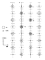
動きクラス検出に使用される動きクラスタップの配置の一例を図5に示す。かかる一例においてフィールドF/o内のラインデータy1およびy2を予測する際に使用される動きクラスタップは、フィールドF/o内の画素n1,n3,n5,およびフィールドF/e内の画素n2,n4,n6,並びにフィールドF−1/e内の画素m2,m4,m6,さらに、フィールドF−1/o内の画素m1,m3,m5である。ここで、画素m1と画素n1,画素m2と画素n2,‥‥,画素m6と画素n6の垂直方向の位置が一致している。但し、動きクラスタップの配置はこれに限定されるものでは無い。
【0037】
図3および図4に示したような空間クラスタップ配置を使用して、1ビットADRCでクラス分類する場合には、y1,y2について動きクラス値を共通とし、動きクラス値の分類数を4とすると、クラス数はそれぞれ以下のようになる。
【0038】
y1についてのクラス数 = 25 ×4 = 128
y2についてのクラス数 = 26 ×4 = 256
この場合、合計のクラス数は384である。但し、例えば画像情報変換処理系に備えられるメモリー資産(図2中では係数メモリ41)がこのクラス数に対応するために充分な記憶容量を有しない場合、または、より少ないクラス数で効率的に画像情報変換処理を行う場合等においては、クラスの総数を削減する必要がある。そこで、この発明は、クラス値変換処理を行うことによってy1,y2についてのクラス数を削減するようにしたものである。図6は、この場合のクラス総数の削減について模式的に示すものである。なお、図6中の仮予測係数については後述する。
【0039】
次に、学習、すなわち適切な予測係数を設定する処理について以下に説明する。まず、学習の第1段階である、クラス値変換テーブルの作成に係る処理系の構成の一例を図7に示す。出力画像信号と同じ信号形式を有する既知の信号(例えば525p信号)が間引きフィルタ51、および正規方程式加算回路61、62に供給される。間引きフィルタ51は、水平方向および垂直方向で画素数がそれぞれ1/2とされ、全体として供給される信号の1/4の画素数を有するSD信号(例えば525i信号)を生成する。
【0040】
かかる処理として、例えば、入力する画像信号について垂直方向の周波数が1/2になるように垂直間引きフィルタによって画素を間引き、さらに、水平方向の周波数が1/2になるように水平間引きフィルタによって画素を間引く等の処理が行われる。間引きフィルタ51の特性を変えることによって学習の特性を変え、それによって、変換して得られる画像の画質を制御することができる。
【0041】
ここで、間引きフィルタ51に対する入力SD信号の一例としての525p信号と、間引きフィルタ51からの出力画像信号の一例としての525i信号との間の画素の空間的関係を図8に示す。525p信号の奇数番目のフィールドでは、偶数番目のラインが間引かれ、また、奇数番目のラインにおいて画素が水平方向に交互に間引かれる。この間引き処理の様子を、図8では、第1フィールドと第3フィールドについて図示した。一方、525p信号の奇数番目のフィールドでは、奇数番目のラインが間引かれ、また、偶数番目のラインにおいて画素が水平方向に交互に間引かれる。この間引き処理の様子を、図8では、第2フィールドについて図示した。
【0042】
図7において、間引きフィルタ51が生成するインターレス画像信号がタップ選択回路101、110、111および120に供給される。タップ選択回路101は、後述する正規方程式の計算において使用され得る予測タップを選択し、選択した予測タップを正規方程式加算回路61、62に供給する。一方、タップ選択回路110、111は、それぞれ、ラインデータy1,y2についての空間クラスタップを選択し、選択した空間クラスタップをそれぞれ、空間クラス検出回路112、113に供給する。さらに、タップ選択回路120は、動きクラスタップを選択し、選択した動きクラスタップを動きクラス検出回路121に供給する。
【0043】
空間クラス検出回路112、113は、空間クラスタップのデータをADRCによって圧縮し、それぞれ、y1,y2についての空間クラス値を独立に検出する。また、動きクラス検出回路121は、動きクラス値を検出する。空間クラス検出回路112の出力と動きクラス検出回路121の出力とがクラス合成回路130に供給される。また、空間クラス検出回路113の出力と動きクラス検出回路121の出力とがクラス合成回路131に供給される。クラス合成回路130、131は、それぞれy1,y2についての空間クラス値と動きクラス値とを合成する。クラス合成回路130、131の出力が正規方程式加算回路61、62に供給される。
【0044】
正規方程式加算回路61は、入力SD信号、タップ選択回路101の出力、およびクラス合成回路130の出力に基づいてy1の予測生成に係る予測係数を解とする正規方程式に係るデータを得るための加算を行う。同様に、正規方程式加算回路62は、入力SD信号、タップ選択回路101の出力、およびクラス合成回路131の出力に基づいてy2の予測生成に係る予測係数を解とする正規方程式に係るデータを得るための加算を行う。
【0045】
正規方程式加算回路61、62は、それぞれ、算出したデータを仮予測係数決定回路63に供給する。仮予測係数決定回路63は、供給されるデータに基づき、正規方程式を解く計算処理を行って、y1,y2の予測生成に係る仮予測係数を算出する。そして、算出した仮予測係数を近接係数クラス統合処理部64に供給する。ここで、仮予測係数と称するのは、最終的な予測係数は、後述するように、クラス統合の結果として決定されるからである。正規方程式を解くための計算処理は、後述する予測係数決定回路263(図9参照)における計算処理と同様である。
【0046】
近接係数クラス統合処理部64は、供給される仮予測係数の間の距離dを、例えば以下の式(4)に従って計算する。
【0047】
【数2】
ここで、kl 、kl ’は相異なるクラスの予測係数を示す。また、lは、予測タップの番号を示す。また、nが予測タップの総数を表す。
【0049】
さらに、近接係数クラス統合処理部64は、上述したようにして求めたクラス間の予測係数の距離を所定のしきい値と比較し、互いの距離がしきい値より小さくなるような複数個のクラスを1つのクラスに統合する。クラスを統合することによってクラスの総数を減らすことができる。この際に、あるクラスと他の幾つかのクラスとの間の距離が共にしきい値より小さくなる場合には、距離が最小となるクラス同志を統合するようにすれば良い。上述の所定のしきい値を大きく設定する程、クラス数を削減することができる。従って、しきい値を可変することにより、クラス値変換処理によって得られるクラスの総数を調整することができる。
【0050】
この際に、画像情報変換処理系に備えられるメモリ資産(図2中では係数メモリ41)の記憶容量等の条件に応じて、y1、y2について的確なクラス数を割り振るようにすることにより、メモリ資産をより有効に使用できる、または、より少ないクラス数で効率的に画像情報変換処理を行うことができる、等の効果を得ることができる。
【0051】
そして、近接係数クラス統合処理部64は、クラスの統合に関する情報をクラス値変換テーブル生成部65に供給する。クラス値変換テーブル生成部65は、供給される情報に基づいてクラス値変換テーブルを生成する。このクラス値変換テーブルは、上述したクラス値変換回路32、33(図2参照)、および後述するクラス値変換回路81、82(図9参照)に供給され、記憶される。そして、これらの構成要素の動作において参照される。
【0052】
次に、学習の第2段階としての予測係数の算出処理について詳細に説明する。図9に、予測係数を算出する予測係数算出処理系の構成の一例を示す。出力画像信号と同じ信号形式を有する既知の信号(例えば525p信号)が間引きフィルタ251、正規方程式加算回路261、262に供給される。間引きフィルタ251は、水平方向および垂直方向で画素数がそれぞれ1/2とされ、全体として供給される信号の1/4の画素数を有するSD信号(例えば525i信号)を生成する。
【0053】
かかる処理として、例えば、入力する画像信号について垂直方向の周波数が1/2になるように垂直間引きフィルタによって画素を間引き、さらに、水平方向の周波数が1/2になるように水平間引きフィルタによって画素を間引く等の処理が行われる。間引きフィルタ51の特性を変えることによって学習の特性を変え、それによって、変換して得られる画像の画質を制御することができる。間引きフィルタ251が生成するSD信号がタップ選択回路201、210、211、220に供給される。間引きフィルタ251の特性を変えることによって学習の特性を変え、それによって、変換して得られる画像の画質を制御することができる。
【0054】
タップ選択回路201は、予測タップを選択し、選択した予測タップを正規方程式加算回路261、262に供給する。一方、タップ選択回路210、211が選択する,y1,y2についての空間クラスタップがそれぞれ空間クラス検出回路212、213に供給される。さらに、タップ選択回路220が選択する予測タップが動きクラス検出回路221に供給される。
【0055】
空間クラス検出回路212、213は、供給される空間クラスタップに基づいて、それぞれy1,y2についての空間クラス値を検出する。また、動きクラス検出回路221は、供給される動きクラスタップに基づいて、動きクラス値を検出する。空間クラス検出回路212の出力と動きクラス検出回路221の出力とがクラス合成回路230に供給される。また、空間クラス検出回路212の出力と動きクラス検出回路221の出力とがクラス合成回路231に供給される。クラス合成回路230、231は、それぞれy1,y2についてクラス値を合成し、各クラス値をクラス値変換処理部81、82に供給する。
【0056】
クラス値変換処理部81、82は、上述したようにして生成されるクラス値変換テーブルを記憶しており、かかるクラス値変換テーブルを参照して、クラス合成回路230、231の出力に対してクラス値変換を施す。そして、クラス値変換の結果を、それぞれ、正規方程式加算回路261、262に供給する。
【0057】
正規方程式加算回路261、262は、予測係数を解とする正規方程式を解くための計算処理に使用されるデータを算出する。すなわち、正規方程式加算回路261は、入力SD信号、タップ選択回路201の出力、およびクラス値変換回路81の出力に基づいて加算処理を行うことにより、y1の予測生成に係る予測係数を解とする正規方程式を解くために必要なデータを算出する。また、正規方程式加算回路262は、入力SD信号、タップ選択回路201の出力、およびクラス値変換回路82の出力に基づいて加算処理を行うことにより、y2の予測生成に係る予測係数を解とする正規方程式を解くために必要なデータを算出する。
【0058】
正規方程式加算回路261、262が算出したデータが予測係数決定回路263に供給される。予測係数決定回路263は、供給されるデータに基づいて正規方程式を解くための計算処理を行い、ラインデータy1,y2の予測生成に係る予測係数を算出する。算出される予測係数が係数メモリ84に供給され、記憶される。
【0059】
予測係数の決定に係る処理、すなわち正規方程式加算回路261、262、および予測係数決定回路263が行う処理について、以下、より詳細に説明する。まず、正規方程式について説明する。上述したように、n個の予測タップを使用して、ラインデータy1,y2を構成する各画素を式(1)によって順次予測生成することができる。
【0060】
式(1)において、学習前は予測係数w1 ,‥‥,wn が未定係数である。学習は、クラス毎に複数の信号データに対して行う。信号データの総数をmと表記する場合、式(1)に従って、以下の式(5)が設定される。
【0061】
yk =w1 ×xk1+w2 ×xk2+‥‥+wn ×xkn (5)
(k=1,2,‥‥,m)
m>nの場合、予測係数w1 ,‥‥,wn は一意に決まらないので、誤差ベクトルeの要素ek を以下の式(6)で定義して、式(7)によって定義される誤差ベクトルeを最小とするように予測係数を定めるようにする。すなわち、いわゆる最小2乗法によって予測係数を一意に定める。
【0062】
ek =yk −{w1 ×xk1+w2 ×xk2+‥‥+wn ×xkn} (6)
(k=1,2,‥‥m)
【0063】
【数3】
式(7)のe2 を最小とする予測係数を求めるための実際的な計算方法としては、e2 を予測係数wi (i=1,2‥‥)で偏微分し(式(8))、iの各値について偏微分値が0となるように各予測係数wi を定めれば良い。
【0065】
【数4】
式(8)から各予測係数wi を定める具体的な手順について説明する。式(9)、(10)のようにXji,Yi を定義すると、式(8)は、式(11)の行列式の形に書くことができる。
【0067】
【数5】
【数6】
【数7】
式(11)が一般に正規方程式と呼ばれるものである。正規方程式加算回路261、262のそれぞれは、クラス値変換回路81、82から供給されたクラス値、予測タップ選択回路201から供給される予測タップ、および入力画像信号と同じ信号形式を有する既知の画像信号を用いて、正規方程式データ、すなわち、式(9)、(10)に従うXji,Yi の値を算出する。そして、算出した正規方程式データを予測係数決定部43に供給する。予測係数決定部43は、正規方程式データに基づいて、掃き出し法等の一般的な行列解法に従って正規方程式を解くための計算処理を行って予測係数wi を算出する。
【0071】
なお、以上のように生成される予測係数は、クラス値変換が施されたデータに基づいて算出されるのに対し、図7を参照して上述した仮予測係数は、クラス値変換が未だ施されていないデータに基づいて算出される。かかる点以外では、両者は正規方程式の解として全く同様な計算処理によって算出される。従って、仮予測係数の決定に係る処理、すなわち図7中の正規方程式加算回路61、62、および予測係数決定回路63が行う処理も、全く同様なものである。
【0072】
すなわち、図7では、クラス合成回路130、131から供給されるクラス値、予測タップ選択回路101から供給される予測タップ、および出力画像信号と同じ信号形式を有する既知の入力画像信号(例えば525p信号)を用いて、正規方程式加算回路61、62のそれぞれが正規方程式データ、すなわち、式(9)、(10)に従うXji,Yi の値を算出する。そして、算出した正規方程式データを仮予測係数決定部63に供給する。仮予測係数決定部63は、正規方程式データに基づいて、掃き出し法等の一般的な行列解法に従って正規方程式を解くための計算処理を行って仮予測係数を算出する。
【0073】
このように、仮予測係数を算出し、それに基づいてクラス値変換テーブルを生成し、さらに、クラス値変換テーブルを参照してクラス値変換を行いながら予測係数を算出することによって、学習が行なわれる。その結果として、予測係数メモリ84には、クラス毎に、プログレッシブ画像の注目画素を推定するための、統計的に最も真値に近い推定ができる予測係数が格納される。予測係数メモリ84に格納された予測係数は、図2等を参照して上述した画像情報変換処理系内の予測係数メモリ41にロードされる。
【0074】
なお、図5示したような画像信号変換処理系、図7に示したようなクラス値変換テーブルの作成に係る処理系、および図9に示した予測係数の決定に係る処理系は、各々別個に設けても良いし、スイッチ等を適宜設けることによって構成要素を共通に使用するように構成しても良い。但し、これらの処理系を別個に設ける場合には、学習の有効性を担保するため、同一の機能を有する構成要素は、同一の動作特性を有するものを使用する必要がある。例えばタップ選択回路1、51、201は、同一の動作特性を有する必要がある。構成要素を共通に使用する場合には、スイッチング等に起因して装置全体の処理が複雑化するが、装置全体に関わる回路規模、コスト等の削減に寄与することができる。
【0075】
また、タップ選択回路201が出力する予測タップの個数は、画像情報変換処理系において使用される予測タップの個数より大きいものとされる。従って、図9中の予測係数決定部263では、クラス毎により多くの係数が求まる。このようにして求まった予測係数の中で、絶対値が大きいものから順に使用する数の予測係数が選択される。
【0076】
次に、線順序変換回路6が行うライン倍速処理について説明する。上述したようにして推定予測演算回路4、5が生成する525p信号の水平周期は、画像情報変換処理がなされる前の525i信号の水平周期と同一である。線順序変換回路6は、ラインメモリを有し、水平周期を2倍とするライン倍速処理を行う。図10は、ライン倍速処理をアナログ波形を用いて示すものである。推定予測演算回路4、5によって、ラインデータy1およびy2が同時に予測生成される。
【0077】
ラインデータy1には、順にa1,a2,a3‥‥のラインが含まれ、ラインデータy2には、順にb1,b2,b3‥‥のラインが含まれる。線順序変換回路500内には、ラインダブラ(図示せず)とスイッチング回路(図示せず)とが設けられている。ラインダブラは、各ラインのデータを時間軸方向に1/2に圧縮し、圧縮されたデータをスイッチング回路に供給する。スイッチング回路は、供給されるデータを交互に選択して出力する。以上のようにして、線順次出力(a0,b0,a1,b1,‥‥)が形成される。
なお、この一実施形態では、現存ライン上の出力画素値(ラインデータL1)と、作成ライン上の出力画素値(ラインデータL2)とを並列構成でもって作成するようにしている。これに対し、メモリを追加し、回路の動作速度が速ければ時分割処理でラインデータy1およびy2を順に生成すると共に、ライン倍速処理を行うように構成しても良い。
【0078】
上述したこの発明の一実施形態においては、図3、図4を参照して上述したように、空間クラスタップの配置がy1,y2について別個のもの(y1について5個、y2について6個)とされていた。これに対して、空間クラスタップの配置をy1,y2について同一とした、この発明の他の実施形態も可能である。
【0079】
以下、他の実施形態について説明する。他の実施形態におけるy1,y2について空間クラスタップの配置について、図11に示す。図11での表記は図3と同様である。フィールドF/o内のラインデータy1、y2についての空間クラスタップとして、フィールドF−1/e内のT5,T6,およびフィールドF/o内のT2,T3,T4,並びにフィールドF/e内のT1の全部で6個の画素値が使用される。この場合、y1,y2について動きクラス値を共通とし、動きクラス値の分類数を4とすると、y1,y2の何れについても、クラス数は、26 ×4=256個となる。
【0080】
この場合にクラス値変換を行うことによってクラス数が削減される様子を、図12に模式的に示す。クラス値変換が施される前のクラス数は、y1,y2の何れについても256クラスである。これに対し、クラス値変換が施された後のクラス数は、y1についてのクラス数の方がy2についてのクラス数よりも小さい。これは、上述したように、y2を予測生成する方がy1を予測生成するよりも困難であることを考慮したためである。
【0081】
他の実施形態における画像情報変換処理系の構成について、図13を参照して説明する。図13において、図2と同様な構成要素については同一の符号を付した。上述したように、他の実施形態ではy1,y2についての空間クラスタップの配置が同一とされるので、空間クラス検出に係る構成は、y1,y2について共通に設ければ良い。このような構成として、空間クラス検出回路16、およびその前段で空間クラスの選択を行うタップ選択回路15が設けられている。
【0082】
空間クラス検出回路16の出力である空間クラス値と、動きクラス検出回路21の出力である動きクラス値とがクラス合成回路17に供給される。クラス合成回路17は、供給される空間クラス値と動きクラス値とを合成する。クラス合成回路17の出力がクラス値変換回路18、19に供給される。クラス値変換回路18、19は、クラス合成回路17の出力にクラス値変換を施すことにより、それぞれ、y1,y2に係る、変換されたクラス値を生成する。この際のクラス値変換は、y1とy2のそれぞれを予測生成する際の困難さを考慮して、的確なクラス数を得るものとされる。クラス値変換回路18、19の出力が係数メモリ41に供給される。
【0083】
以上のような他の実施形態では、空間クラス検出に係る構成をy1,y2について共通とすることができるので、回路構成の簡素化に寄与することができる。その反面、y1について大きな比率でクラス数を削減するクラス値変換を行う必要があるので、特にy1についてのクラス値変換が複雑な処理となる可能性がある。なお、図2と同様に空間クラス検出に係る構成をy1,y2について別個に設ける構成を用いても、他の実施形態に係る画像情報変換処理を実現することは可能である。
【0084】
また、この発明の一実施形態および他の実施形態は、525i信号を525p信号に変換するものであるが、525本のライン数は、一例であって、他のライン数であってもこの発明を適用することができる。例えば、入力SD信号における水平方向の画素数に対して、2倍以外の画素数を含むラインからなる出力画像信号を予測生成するようにしても良い。より具体的には、出力画像信号として1050i信号、すなわち走査線数が1050本でインターレス方式の画像信号を予測生成する画像情報変換処理を行う場合に、この発明を適用することができる。
【0085】
このような画像情報変換処理について具体的に説明する。図14は、1フィールドの画像の一部を拡大することによって、525i信号と、1050i信号とにおける画素の配置を示すものである。大きなドットが525i信号の画素を示し、また、小さなドットが1050i信号の画素を示す。なお、図14の実線で示したものは、あるフレームの奇数フィールドの画素配置である。他のフィールド(偶数フィールド)のラインは、点線で示すように空間的に0.5ラインずれたものであり、ラインデータy1’,y2’の画素が形成される。
【0086】
図15に、この場合の空間クラスタップの配置の一例を示す。図15中での表記は図3と同様である。フィールドF/o内のラインデータy1、y2についての空間クラスタップとして、フィールドF−1/e内のT4,T5,T6,T7およびフィールドF/o内のT1,T2,T3の全部で7個の画素値が使用される。この場合、y1,y2について動きクラス値を共通とし、動きクラス値の分類数を4とすると、クラス数はy1,y2の何れについても、27 ×4=512個となる。
【0087】
このような空間クラスタップ配置を用いる場合には、例えば図13等を参照して上述した他の実施形態と同様な構成によって画像情報変換処理を実現することができる。なお、空間クラスタップの配置はこれに限定されるものでは無い。例えば、y1,y2について異なる空間クラスタップ配置を用いても良い。また、水平方向の複数の入力画素を使用しても良い。
【0088】
また、図16に、この場合の動きクラスタップの配置の一例を示す。フィールドF/o内のラインデータy1およびy2を予測する際に使用される動きクラスタップは、フィールドF/o内の画素n1,n3,n5,およびフィールドF/e内の画素n2,n4,n6,並びにフィールドF−1/e内の画素m2,m4,m6,さらに、フィールドF−1/o内の画素m1,m3,m5である。ここで、画素m1と画素n1,画素m2と画素n2,‥‥,画素m6と画素n6の垂直方向の位置が一致している。但し、この場合の動きクラスタップの配置はこれに限定されるものでは無い。
【0089】
【発明の効果】
上述したように、この発明は、入力画像信号から走査線構造の異なる出力画像信号を形成する画像情報変換処理を行うに際して、入力画像信号の走査線との位置関係が異なる複数種類の注目点(具体的には、入力画像信号の走査線上に位置するy1と、入力画像信号の走査線の間に位置するy2等)の各々について決定されるクラスの数を、注目点の入力画像信号の走査線に対する位置関係に応じて(例えば、予測生成がより困難なy2に対してより多くのクラス数を割当てる等)、削減するようにしたものである。
【0090】
このため、装置内のメモリ資産の記憶容量に応じてクラス数を設定できるので、メモリ資産の記憶容量が小さい場合にも的確な処理を行うことが可能となる。また、より少ないクラス数の下で効率的な処理を行う場合にも、この発明を適用することが有効となる。
【0091】
また、注目点と入力画像信号の走査線との位置関係の違い等に起因する(具体的にはy1とy2の間での)予測生成の困難さに応じて、各注目点に対して適切なクラス数が割り当てられる。このため、メモリ資産の記憶容量が限られている場合にも、きめ細かく、また効率的な画像情報変換処理を行うことが可能となる。
【図面の簡単な説明】
【図1】この発明の一実施形態によってなされる画像情報変換処理における画素の配置の一例を示す略線図である。
【図2】この発明の一実施形態における画像情報変換処理系の構成の一例を示すブロック図である。
【図3】この発明の一実施形態における、ラインデータy1についての空間クラスタップ配置の一例を示す略線図である。
【図4】この発明の一実施形態における、ラインデータy2についての空間クラスタップ配置の一例を示す略線図である。
【図5】この発明の一実施形態における、動きクラスタップ配置の一例を示す略線図である。
【図6】この発明の一実施形態におけるクラス統合について説明するための略線図である。
【図7】この発明の一実施形態におけるクラス値変換テーブル生成処理系の構成の一例を示すブロック図である。
【図8】クラス値変換テーブル生成処理系および予測係数算出処理系において使用される間引きフィルタによる処理について説明するための略線図である。
【図9】この発明の一実施形態における、予測係数算出処理系の構成の一例を示すブロック図である。
【図10】ライン倍速処理について説明するための略線図である。
【図11】この発明の他の実施形態における、空間クラスタップ配置の一例を示す略線図である。
【図12】この発明の他の実施形態におけるクラス統合について説明するための略線図である。
【図13】この発明の他の実施形態における画像情報変換処理系の構成の一例を示すブロック図である。
【図14】この発明の他の実施形態によってなされる画像情報変換処理における画素の配置の一例を示す略線図である。
【図15】この発明の一実施形態における、空間クラスタップ配置の一例を示すブロック図である。
【図16】この発明の一実施形態における、動きクラスタップ配置の一例を示すブロック図である。
【符号の説明】
32、33・・・クラス値変換回路、41・・・係数メモリ、64・・・近接係数クラス統合、65・・・クラス値変換テーブル生成部、81、82・・・クラス値変換回路、18、19・・・クラス値変換回路[0001]
BACKGROUND OF THE INVENTION
The present invention relates to an image information conversion apparatus, an image information conversion method, and a television receiver having a function of generating an image signal having a higher resolution from an input image signal.
[0002]
[Prior art]
For the purpose of obtaining an image signal having a higher resolution than the input image signal, an image information conversion process for forming an output image signal having a scanning line structure different from that of the input image signal is performed. As the image information conversion process, there is a class classification adaptive process in which class division is performed according to the three-dimensional (spatio-temporal) distribution of the signal level of the input image signal, and pixel prediction is performed by referring to the class value obtained thereby. Proposed. In such processing, when pixels are predicted and generated at positions corresponding to the scanning lines of the input image signal, there is a greater difficulty than when pixels are predicted and generated at positions that do not correspond to the scanning lines of the input image signal.
[0003]
For this reason, by assigning a larger number of classes to positions that do not correspond to the scanning lines of the input image signal so that the prediction generation of pixels at such positions is performed more finely, it is particularly retained corresponding to the class classification. From the standpoint of using a memory for storing data related to the prediction generation process, more efficient processing is possible.
[0004]
On the other hand, the larger the number of classes, the larger the memory capacity necessary for performing the image information conversion process. Therefore, considering that the storage capacity is limited in an actual device, it is necessary to reduce the total number of classes.
[0005]
[Problems to be solved by the invention]
Accordingly, an object of the present invention is to assign an appropriate number of classes according to conditions such as a positional relationship between a position where a pixel is predicted and generated and a scanning line of an input image signal, a storage capacity of a memory provided in the apparatus, and the like. It is an object to provide an image information conversion apparatus, an image information conversion method, and a television receiver.
[0006]
[Means for Solving the Problems]
According to a first aspect of the present invention, there is provided an image information conversion apparatus configured to form an output image signal having a different scanning line structure from an input image signal.
A plurality of points of interest that are not present in the input image signal and that are not present in the input image signal and that are adjacent in terms of time or space to the second point of interest on the generated scanning line. First image data selection means for selecting the pixels from the input image signal;
A level distribution pattern is detected from the image data selected by the first image data selection means, and the first and second attention points belong to the detected pattern.FirstClass detection means for determining a class value of 1;
For the first class value of each of the first and second points of interest,Apply the class value conversion process with reference to the class value conversion table generated in advance by learning.No.Class value conversion means for generating a class value of 2,
Input image signalEt al.Second image data selection means for selecting a plurality of pixels located near each of the first and second attention points in terms of time or space;
By the second image data selection meansSelectedSpecified in correspondence with the image data and the second class valueFirstBy linear linear combination of the prediction coefficient data, the firstThe image data selected by the second image data selection means and the second prediction coefficient data specified in correspondence with the second class value are subjected to calculation processing for predictively generating a pixel at the target point of The pixel at the second point of interest isArithmetic processing means for performing arithmetic processing for predictive generation;
Sought by learning in advance,Used for arithmetic processing by arithmetic processing means,First and secondPrediction coefficient dataFor every second class valueMemoryIsStorage means,
First attention in the image signal having the same resolution as the output image signalThe true pixel of the pixel corresponding to the pointValue, image data corresponding to the image data selected by the second image data selection means, andFirstIn order to minimize the difference from the calculated value of the linear linear combination of the temporary prediction coefficients,The first for each first class valueProvisional prediction coefficient isSought by learning,
The true pixel value of the pixel corresponding to the second target point in the image signal having the same resolution as the output image signal, the image data corresponding to the image data selected by the second image data selection means, and the first A second temporary prediction coefficient is obtained by learning for each first class value so as to minimize a difference between the calculated value of the linear prediction combination of the two temporary prediction coefficients and
The first determined for different first class valuesCalculate the sum or average of distances as differences between provisional prediction coefficientsAndThe sum or average of distances isFirstCombine multiple first class values that are less than or equal to the threshold into one class to generate a second class value with fewer classes than the first class valueAnd
A sum or average value of distances as a difference between second temporary prediction coefficients obtained for different first class values is calculated, and the sum or average value of distances is equal to or less than a second threshold value. The first class value of, into a single class to generate a second class value with fewer classes than the first class value;
The class value conversion table contains the conversion rule for converting the first class value to the second class value.This is an image information processing apparatus.
[0007]
According to a second aspect of the present invention, there is provided an image information conversion apparatus configured to form an output image signal having a different scanning line structure from an input image signal.
The first attention point on the scanning line existing in the scanning line of the input image signal and the second attention point on the generated scanning line not existing in the input image signal are close in time or space. First image data selection means for selecting a plurality of pixels located from an input image signal;
A level distribution pattern is detected from the image data selected by the first image data selection means, and a space class value indicating a space class to which the first and second attention points belong is determined based on the detected pattern. A space class detection means;
Second image data selection means for selecting, from the input image signal, a plurality of pixels located in the vicinity of each of the first and second attention points in terms of time or space in a plurality of frames in the input image signal. When,
Motion class detection means for calculating a sum of absolute differences between frames from image data selected by the second image data selection means, and determining a motion class value representing motion based on the calculation result;
Class combining means for generating a first class value by combining the spatial class value and the motion class value;
For the first class value of each of the first and second points of interest,Apply the class value conversion process with reference to the class value conversion table generated in advance by learning.No.Class value conversion means for generating a class value of 2,
Input image signalEt al.Each of the first and second attention pointsAtA third image data selection means for selecting a plurality of pixels located near each other in space or space;
By the third image data selection meansSelectedSpecified in correspondence with the image data and the second class valueFirstBy linear linear combination of the prediction coefficient data, the firstThe image data selected by the third image data selection means and the second prediction coefficient data specified in correspondence with the second class value are subjected to the calculation processing for predictively generating the pixel at the attention point The pixel at the second point of interest isArithmetic processing means for performing arithmetic processing for predictive generation;
Sought by learning in advance,Used for arithmetic processing by arithmetic processing means,First and secondPrediction coefficient dataFor every second class valueMemoryIsStorage means,
First attention in the image signal having the same resolution as the output image signalThe true pixel of the pixel corresponding to the pointValue, image data corresponding to the image data selected by the third image data selection means, andFirstIn order to minimize the difference from the calculated value of the linear linear combination of the temporary prediction coefficients,The first for each first class valueProvisional prediction coefficient isSought by learning,
The true pixel value of the pixel corresponding to the second point of interest in the image signal having the same resolution as the output image signal, the image data corresponding to the image data selected by the third image data selection means, and the first A second temporary prediction coefficient is obtained by learning for each first class value so as to minimize a difference between the calculated value of the linear prediction combination of the two temporary prediction coefficients and
The first determined for different first class valuesCalculate the sum or average of distances as differences between provisional prediction coefficientsAndThe sum or average of distances isFirstCombine multiple first class values that are less than or equal to the threshold into one class to generate a second class value with fewer classes than the first class valueAnd
A sum or average value of distances as a difference between second temporary prediction coefficients obtained for different first class values is calculated, and the sum or average value of distances is equal to or less than a second threshold value. The first class value of, into a single class to generate a second class value with fewer classes than the first class value;
The class value conversion table contains the conversion rule for converting the first class value to the second class value.This is an image information processing apparatus.
[0008]
Claim7The present invention provides an image information conversion method in which an output image signal having a different scanning line structure is formed from an input image signal.
A plurality of points of interest that are not present in the input image signal and that are not present in the input image signal and that are adjacent in terms of time or space to the second point of interest on the generated scanning line. A first image data selection step of selecting a pixel of the input image signal from an input image signal;
A level distribution pattern is detected from the image data selected in the first image data selection step, and the first and second attention points belong based on the detected pattern.FirstA class detection step for determining a class value of 1;
For the first class value of each of the first and second points of interest,Apply the class value conversion process with reference to the class value conversion table generated in advance by learning.No.A class value conversion step for generating two class values;
Input image signalEt al.First and second attention pointsNosoA second image data selection step for selecting a plurality of pixels located in the vicinity in time or space respectively;
Sought by learning in advance,Used for arithmetic processing by arithmetic processing steps,First and secondPrediction coefficient dataFor every second class valueMemoryIsFrom storage meansFirst and secondOutputting prediction coefficient data;
By the second image data selection stepSelectedSpecified in correspondence with the image data and the second class valueFirstBy linear linear combination of the prediction coefficient data, the firstThe image data selected by the second image data selection step and the second prediction coefficient data designated in correspondence with the second class value are subjected to calculation processing for predictively generating a pixel at the target point of The pixel at the second point of interest isAn arithmetic processing step for performing arithmetic processing for predictive generation,
First attention in the image signal having the same resolution as the output image signalThe true pixel of the pixel corresponding to the pointValue, image data corresponding to the image data selected in the second image data selection step, andFirstIn order to minimize the difference from the calculated value of the linear linear combination of the temporary prediction coefficients,The first for each first class valueProvisional prediction coefficient isSought by learning,
The true pixel value of the pixel corresponding to the second target point in the image signal having the same resolution as the output image signal, the image data corresponding to the image data selected in the second image data selection step, and the first A second temporary prediction coefficient is obtained by learning for each first class value so as to minimize a difference between the calculated value of the linear prediction combination of the two temporary prediction coefficients and
First determined for different first class valuesCalculate the sum or average of distances as differences between provisional prediction coefficientsAndThe sum or average of distances isFirstCombine multiple first class values that are less than or equal to the threshold into one class to generate a second class value with fewer classes than the first class valueAnd
A sum or average value of distances as a difference between second temporary prediction coefficients obtained for different first class values is calculated, and the sum or average value of distances is equal to or less than a second threshold value. The first class value of, into a single class to generate a second class value with fewer classes than the first class value;
The class value conversion table contains a conversion rule for converting the first class value to the second class value.This is an image information conversion method characterized by the above.
[0009]
Claim8The present invention provides an image information conversion method in which an output image signal having a different scanning line structure is formed from an input image signal.
The first attention point on the scanning line that exists in the scanning line of the input image signal and the second attention point on the generated scanning line that does not exist in the input image signal are temporally or spatially adjacent to each other. A first image data selection step for selecting a plurality of pixels from an input image signal, and a level distribution pattern is detected from the image data selected by the first image data selection step. Based on the detected pattern A space class detecting step for determining a space class value indicating a space class to which the first and second attention points respectively belong;
Second image data selection step for selecting, from the input image signal, a plurality of pixels located in the vicinity of each of the first and second attention points in terms of time or space in a plurality of frames in the input image signal. When,
A motion class detection step of calculating a sum of absolute differences between frames from the image data selected by the second image data selection step, and determining a motion class value representing motion based on the calculation result;
A class synthesis step of synthesizing the space class value and the motion class value to generate a first class value;
For the first class value of each of the first and second points of interest,Apply the class value conversion process with reference to the class value conversion table generated in advance by learning.No.A class value conversion step for generating two class values;
Input image signalEt al.Each of the first and second attention pointsAtA third image data selection step for selecting a plurality of pixels located near each other in space or space;
Sought by learning in advance,Used for arithmetic processing by arithmetic processing steps,First and secondPrediction coefficient dataFor every second class valueMemoryIsFrom storage meansFirst and secondOutputting prediction coefficient data;
By the third image data selection stepSelectedSpecified in correspondence with the image data and the second class valueFirstBy linear linear combination of the prediction coefficient data, the firstThe image data selected by the third image data selection step and the second prediction coefficient data designated in correspondence with the second class value are calculated for performing a prediction process for generating a pixel at the target point of The pixel at the second point of interest isAn arithmetic processing step for performing arithmetic processing for predictive generation,
First attention in the image signal having the same resolution as the output image signalThe true pixel of the pixel corresponding to the pointValue, image data corresponding to the image data selected in the third image data selection step, andFirstIn order to minimize the difference from the calculated value of the linear linear combination of the temporary prediction coefficients,The first for each first class valueProvisional prediction coefficient isSought by learning,
The true pixel value of the pixel corresponding to the second target point in the image signal having the same resolution as the output image signal, the image data corresponding to the image data selected by the third image data selection step, and the first A second provisional prediction coefficient is obtained by learning for each first class value so as to minimize the difference between the calculated value of the linear first combination of the provisional prediction coefficients of 2 and
First determined for different first class valuesCalculate the sum or average of distances as differences between provisional prediction coefficientsAndThe sum or average of distances isFirstCombine multiple first class values that are less than or equal to the threshold into one class to generate a second class value with fewer classes than the first class valueAnd
A sum or average value of distances as a difference between second temporary prediction coefficients obtained for different first class values is calculated, and the sum or average value of distances is equal to or less than a second threshold value. The first class value of, into a single class to generate a second class value with fewer classes than the first class value;
The class value conversion table contains a conversion rule for converting the first class value to the second class value.This is an image information processing apparatus.
[0010]
Claim 11According to the present invention, there is provided a television receiver configured to form an output image signal having a different scanning line structure from an input image signal.
A plurality of points of interest that are not present in the input image signal and that are not present in the input image signal and that are adjacent in terms of time or space to the second point of interest on the generated scanning line. First image data selection means for selecting the pixels from the input image signal;
A level distribution pattern is detected from the image data selected by the first image data selection means, and the first and second attention points belong to the detected pattern.FirstClass detection means for determining a class value of 1;
For the first class value of each of the first and second points of interest,Apply the class value conversion process with reference to the class value conversion table generated in advance by learning.No.Class value conversion means for generating a class value of 2,
Input image signalEt al.Second image data selection means for selecting a plurality of pixels located near each of the first and second attention points in terms of time or space;
By the second image data selection meansSelectedSpecified in correspondence with the image data and the second class valueFirstBy linear linear combination of the prediction coefficient data, the firstThe image data selected by the second image data selection means and the second prediction coefficient data specified in correspondence with the second class value are subjected to calculation processing for predictively generating a pixel at the target point of The pixel at the second point of interest isArithmetic processing means for performing arithmetic processing for predictive generation;
Sought by learning in advance,Used for arithmetic processing by arithmetic processing means,First and secondPrediction coefficient dataFor every second class valueMemoryIsStorage means,
First attention in the image signal having the same resolution as the output image signalThe true pixel of the pixel corresponding to the pointValue, image data corresponding to the image data selected by the second image data selection means, andFirstIn order to minimize the difference from the calculated value of the linear linear combination of the temporary prediction coefficients,The first for each first class valueProvisional prediction coefficient isSought by learning,
The true pixel value of the pixel corresponding to the second target point in the image signal having the same resolution as the output image signal, the image data corresponding to the image data selected by the second image data selection means, and the first A second temporary prediction coefficient is obtained by learning for each first class value so as to minimize a difference between the calculated value of the linear prediction combination of the two temporary prediction coefficients and
First determined for different first class valuesCalculate the sum or average of distances as differences between provisional prediction coefficientsAndThe sum or average of distances isFirstCombine multiple first class values that are less than or equal to the threshold into one class to generate a second class value with fewer classes than the first class valueAnd
A sum or average value of distances as a difference between second temporary prediction coefficients obtained for different first class values is calculated, and the sum or average value of distances is equal to or less than a second threshold value. The first class value of, into a single class to generate a second class value with fewer classes than the first class value;
The class value conversion table contains a conversion rule for converting the first class value to the second class value.This is a television receiver.
[0011]
Claim 12According to the present invention, there is provided a television receiver configured to form an output image signal having a different scanning line structure from an input image signal.
The first attention point on the scanning line that exists in the scanning line of the input image signal and the second attention point on the generated scanning line that does not exist in the input image signal are temporally or spatially adjacent to each other. A first image data selection step for selecting a plurality of pixels from an input image signal, and a level distribution pattern is detected from the image data selected by the first image data selection step. Based on the detected pattern A space class detecting step for determining a space class value indicating a space class to which the first and second attention points respectively belong;
Second image data selection step for selecting, from the input image signal, a plurality of pixels located in the vicinity of each of the first and second attention points in terms of time or space in a plurality of frames in the input image signal. When,
A motion class detection step of calculating a sum of absolute differences between frames from the image data selected by the second image data selection step, and determining a motion class value representing motion based on the calculation result;
A class synthesis step of synthesizing the space class value and the motion class value to generate a first class value;
For the first class value of each of the first and second points of interest,Apply the class value conversion process with reference to the class value conversion table generated in advance by learning.No.A class value conversion step for generating two class values;
Input image signalEt al.Each of the first and second attention pointsAtA third image data selection step for selecting a plurality of pixels located near each other in space or space;
Sought by learning in advance,Used for arithmetic processing by arithmetic processing steps,First and secondPrediction coefficient dataFor every second class valueMemoryIsFrom storage meansFirst and secondOutputting prediction coefficient data;
By the third image data selection stepSelectedSpecified in correspondence with the image data and the second class valueFirstBy linear linear combination of the prediction coefficient data, the firstThe image data selected by the third image data selection step and the second prediction coefficient data specified in correspondence with the second class value are calculated in order to predictively generate a pixel at the attention point The pixel at the second point of interest isAn arithmetic processing step for performing arithmetic processing for predictive generation,
First attention in the image signal having the same resolution as the output image signalThe true pixel of the pixel corresponding to the pointValue, image data corresponding to the image data selected in the third image data selection step, andFirstIn order to minimize the difference from the calculated value of the linear linear combination of the temporary prediction coefficients,The first for each first class valueProvisional prediction coefficient isSought by learning,
The true pixel value of the pixel corresponding to the second target point in the image signal having the same resolution as the output image signal, the image data corresponding to the image data selected by the third image data selection step, and the first A second temporary prediction coefficient is obtained by learning for each first class value so as to minimize a difference between the calculated value of the linear prediction combination of the two temporary prediction coefficients and
First determined for different first class valuesCalculate the sum or average of distances as differences between provisional prediction coefficientsAndThe sum or average of distances isFirstCombine multiple first class values that are less than or equal to the threshold into one class to generate a second class value with fewer classes than the first class valueAnd
A sum or average value of distances as a difference between second temporary prediction coefficients obtained for different first class values is calculated, and the sum or average value of distances is equal to or less than a second threshold value. The first class value of, into a single class to generate a second class value with fewer classes than the first class value;
The class value conversion table contains a conversion rule for converting the first class value to the second class value.This is a television receiver.
[0012]
According to the invention as described above, for example, a positional relationship such as whether or not a point of interest, that is, a point where a pixel is to be predicted and generated is at a position corresponding to the scanning line of the input image signal, or provided in the apparatus The number of classes for the target position is accurately set according to conditions such as the storage capacity of the memory. For this reason, it becomes possible to perform an image information conversion process more efficiently.
[0013]
DETAILED DESCRIPTION OF THE INVENTION
Prior to the description of an embodiment of the present invention, image information conversion processing that is the premise thereof will be described below. In this process, a standard resolution digital image signal (hereinafter referred to as an SD signal) is converted into a high resolution image signal (sometimes referred to as an HD signal) and output. As the SD signal at this time, for example, an interlaced image signal (hereinafter referred to as a 525i signal) having 525 lines is used. As the high-resolution image signal, for example, a progressive-type output video signal (hereinafter referred to as a 525p signal) having 525 lines is used. Further, the number of pixels in the horizontal direction in the output image signal is twice the number of pixels in the horizontal direction in the input image signal.
[0014]
In such image information conversion processing, resolution is being improved by class classification adaptation processing according to the proposal of the present applicant. The class classification adaptive processing is different from that in which high resolution signals are formed by conventional interpolation processing. That is, the class classification adaptive processing performs class division according to the three-dimensional (spatio-temporal) distribution of the signal level of the input SD signal, and stores the predicted count value obtained by learning in advance for each class in a predetermined storage unit. This is a process of outputting an optimum estimated value by a calculation based on the prediction formula. With the class classification adaptive processing, it becomes possible to obtain a resolution higher than the resolution of the input SD signal.
[0015]
FIG. 1 shows an example of pixel arrangement in image information conversion processing for converting a 525i signal as an input SD signal into a 525p signal as an output image signal by enlarging a part of an image of one field. is there. A large dot indicates a pixel of the 525i signal, and a small dot indicates a pixel of the 525p signal. Here, FIG. 1 shows a pixel arrangement in an odd field of a certain frame. In the other field (even field), the lines of the 525i signal are spatially shifted by 0.5 lines. As can be seen from FIG. 1, line data y1 at the same position as the line of the 525i signal (shown as small black dots) and line data y2 at the middle position between the upper and lower lines of the 525i signal (shown as white small dots) And 525p signal is predicted and generated.
[0016]
Here, y1 is a point that already exists, whereas y2 is a point generated by a new prediction. Therefore, predicting and generating y2 is more difficult than predicting and generating y1. For this reason, when y2 is predicted and generated, it is necessary to allocate a larger number of classes than when y1 is predicted and generated. In addition, for example, when the memory assets provided in the apparatus do not have a sufficient amount, or when efficient image information conversion processing is performed using a smaller number of classes, the total number of classes should be reduced. Class value conversion needs to be performed. From these viewpoints, according to the present invention, the number of classes is appropriately allocated so that prediction generation of y1 and y2 can be performed efficiently and finely.
[0017]
Hereinafter, an embodiment of the present invention will be described with reference to the drawings as appropriate. In one embodiment, an image information conversion process for converting a 525i signal as an input SD signal into a 525p signal as an output image signal is performed. However, the present invention can also be applied when converting between an input SD signal / output image signal having another image signal format. FIG. 2 is a block diagram showing an example of the configuration of the image information conversion processing system in one embodiment of the present invention. An input SD signal (525i signal) is supplied to the
[0018]
The
[0019]
In addition, prediction coefficients necessary for predicting and estimating the line data y1 and y2 are supplied from the
[0020]
y = w1X1+ W2X2+ ... + wnXn (1)
Where x1, ..., xnIs each prediction tap, w1, ..., wnIs each prediction coefficient. That is, Expression (1) is an expression for predicting and generating the pixel value y using n prediction taps. As the column of pixel values y, the estimated
[0021]
The estimated
[0022]
On the other hand, the
[0023]
The space
[0024]
The
[0025]
The converted class value is supplied to the
[0026]
Here, the space class detection will be described in more detail. In general, the spatial class detection circuit detects a spatial pattern of the level distribution of image data based on the level distribution pattern of the spatial class tap, and generates a spatial class value based on the detected spatial pattern. In this case, in order to prevent the number of classes from becoming enormous, processing for compressing 8-bit input pixel data into data having a smaller number of bits is performed for each pixel. As an example of such information compression processing, ADRC (Adaptive Dynamic Range Coding) can be used. Moreover, DPCM (predictive coding), VQ (vector quantization), etc. can also be used as information compression processing.
[0027]
ADRC is an adaptive requantization method originally developed for high-efficiency coding for VTR (Video Tape Recoder), but it can efficiently express local patterns of signal level with a short word length. In this form, ADRC is used to generate codes for spatial classification. ADRC uses the maximum value MAX and the minimum value MIN according to the following (2), where DR is the dynamic range of the space class tap, n is the bit allocation, L is the data level of the pixel of the space class tap, and Q is the requantization code. Are re-quantized by equally dividing the interval between and with a specified bit length.
[0028]
DR = MAX-
Q = {(L−MIN + 0.5) × 2 / DR} (2)
However, {} means a truncation process.
[0029]
As described above, the number of classes for line data y2 is larger than the number of classes for line data y1. This point will be specifically described. First, FIG. 3 shows an example of the arrangement of space class taps used for space class detection for y1. In FIG. 3, when time advances in the horizontal direction (left to right), the pixels in each field are shown side by side in the vertical direction.
[0030]
The illustrated fields are expressed as F-1 / o, F-1 / e, F / o, and F / e in order from the left. F-1 / o is a notation indicating that the field is composed of an odd-numbered (odd) th scanning line of the F-1th frame. Similarly, F-1 / e means "a field made up of even-numbered (even) scan lines of the F-1th frame", and F / o means "odd-numbered scanlines of the Fth frame". "F / e" means "a field consisting of even-numbered scanning lines of the F-th frame".
[0031]
In such an example, a total of five space class taps for the line data y1 in the field F / o, T4, T5 in the field F-1 / e, and T1, T2, T3 in the field F / o. Pixel values are used. However, the arrangement of the space class taps is not limited to this. For example, a plurality of horizontal input pixels may be used as the space class tap.
[0032]
Similarly, FIG. 4 shows an example of the arrangement of space class taps used for space class detection for y2. The notation in FIG. 4 is the same as in FIG. In such an example, T6 in field F-1 / e, and T2, T3, T4, T5 in field F / o, and field F / as the space class tap for line data y2 in field F / o. A total of 6 pixel values for T1 in e are used. However, the arrangement of the space class taps is not limited to this. For example, a plurality of horizontal input pixels may be used as the space class tap.
[0033]
Next, motion class detection will be described in more detail. The motion
[0034]
[Expression 1]
In Equation (3), n is the number of motion class taps, and can be set to n = 6, for example (see FIG. 5). Then, a motion class value that is a motion index is determined by comparing the value of param with a preset threshold value. For example,
[0036]
An example of the arrangement of motion class taps used for motion class detection is shown in FIG. In such an example, the motion class taps used in predicting line data y1 and y2 in field F / o are pixels n1, n3, n5 in field F / o and pixels n2, n in field F / e. n4, n6, and pixels m2, m4, and m6 in the field F-1 / e, and pixels m1, m3, and m5 in the field F-1 / o. Here, the vertical positions of the pixel m1, the pixel n1, the pixel m2, the pixel n2,..., The pixel m6, and the pixel n6 are the same. However, the arrangement of the motion class taps is not limited to this.
[0037]
In the case of class classification by 1-bit ADRC using the space class tap arrangement as shown in FIG. 3 and FIG. 4, the motion class values are common for y1 and y2, and the number of motion class value classifications is 4. Then, the number of classes is as follows.
[0038]
Number of classes for y1 = 2Five× 4 = 128
Number of classes for y2 = 26× 4 = 256
In this case, the total number of classes is 384. However, for example, when the memory resource (
[0039]
Next, learning, that is, processing for setting an appropriate prediction coefficient will be described below. First, FIG. 7 shows an example of the configuration of a processing system related to creation of a class value conversion table, which is the first stage of learning. A known signal (for example, a 525p signal) having the same signal format as the output image signal is supplied to the thinning
[0040]
As such processing, for example, the pixels are thinned out by a vertical thinning filter so that the frequency in the vertical direction of the input image signal is halved, and further, the pixels by the horizontal thinning filter so that the frequency in the horizontal direction is halved. Processing such as thinning out is performed. By changing the characteristic of the thinning
[0041]
Here, FIG. 8 shows a spatial relationship of pixels between a 525p signal as an example of an input SD signal to the
[0042]
In FIG. 7, the interlaced image signal generated by the thinning
[0043]
The space
[0044]
The normal
[0045]
The normal
[0046]
The proximity coefficient class
[0047]
[Expression 2]
Where kl, Kl'Represents the prediction coefficient of different classes. L indicates the number of the prediction tap. N represents the total number of prediction taps.
[0049]
Furthermore, the proximity coefficient class
[0050]
At this time, an appropriate class number is assigned to y1 and y2 in accordance with conditions such as a storage capacity of a memory asset (
[0051]
Then, the proximity coefficient class
[0052]
Next, prediction coefficient calculation processing as a second stage of learning will be described in detail. FIG. 9 shows an example of a configuration of a prediction coefficient calculation processing system that calculates a prediction coefficient. A known signal (for example, a 525p signal) having the same signal format as the output image signal is supplied to the thinning
[0053]
As such processing, for example, the pixels are thinned out by a vertical thinning filter so that the frequency in the vertical direction of the input image signal is halved, and further, the pixels by the horizontal thinning filter so that the frequency in the horizontal direction is halved. Processing such as thinning out is performed. By changing the characteristic of the thinning
[0054]
The
[0055]
The space
[0056]
The class value
[0057]
The normal
[0058]
Data calculated by the normal
[0059]
Processing related to determination of the prediction coefficient, that is, processing performed by the normal
[0060]
In equation (1), the prediction coefficient w before learning1, ..., wnIs an undetermined coefficient. Learning is performed on a plurality of signal data for each class. When the total number of signal data is expressed as m, the following equation (5) is set according to equation (1).
[0061]
yk= W1Xk1+ W2Xk2+ ... + wnXkn (5)
(K = 1, 2,..., M)
If m> n, prediction coefficient w1, ..., wnIs not uniquely determined, the element e of the error vector ekIs defined by the following equation (6), and the prediction coefficient is determined so as to minimize the error vector e defined by equation (7). That is, the prediction coefficient is uniquely determined by a so-called least square method.
[0062]
ek= Yk-{W1Xk1+ W2Xk2+ ... + wnXkn} (6)
(K = 1, 2, ... m)
[0063]
[Equation 3]
E in equation (7)2As a practical calculation method for obtaining the prediction coefficient that minimizes2Prediction coefficient wi(i = 1, 2...) is partially differentiated (equation (8)), and each prediction coefficient w is set so that the partial differential value becomes 0 for each value of i.iShould be determined.
[0065]
[Expression 4]
From Equation (8), each prediction coefficient wiA specific procedure for determining the above will be described. X as in equations (9) and (10)ji, Yi(8) can be written in the form of the determinant of equation (11).
[0067]
[Equation 5]
[Formula 6]
[Expression 7]
Equation (11) is generally called a normal equation. Each of the normal
[0071]
The prediction coefficient generated as described above is calculated based on the data subjected to the class value conversion, whereas the provisional prediction coefficient described above with reference to FIG. 7 is not yet subjected to the class value conversion. It is calculated based on data that has not been processed. Except for this point, both are calculated by the same calculation process as the solution of the normal equation. Therefore, the processing related to the determination of the temporary prediction coefficient, that is, the processing performed by the normal
[0072]
That is, in FIG. 7, a known input image signal (for example, a 525p signal) having the same signal format as the class value supplied from the
[0073]
Thus, learning is performed by calculating a temporary prediction coefficient, generating a class value conversion table based on the temporary prediction coefficient, and calculating the prediction coefficient while performing class value conversion with reference to the class value conversion table. . As a result, the prediction coefficient memory 84 stores, for each class, a prediction coefficient that can be estimated statistically closest to the true value for estimating the pixel of interest of the progressive image. The prediction coefficient stored in the prediction coefficient memory 84 is loaded into the
[0074]
Note that the image signal conversion processing system as shown in FIG. 5, the processing system related to creation of the class value conversion table as shown in FIG. 7, and the processing system related to determination of the prediction coefficient shown in FIG. The components may be provided in common, or the components may be used in common by appropriately providing a switch or the like. However, when these processing systems are provided separately, in order to ensure the effectiveness of learning, it is necessary to use constituent elements having the same function as those having the same operation characteristics. For example, the
[0075]
The number of prediction taps output from the
[0076]
Next, the line double speed process performed by the line
[0077]
The line data y1 includes lines a1, a2, a3,... In order, and the line data y2 includes lines b1, b2, b3,. In the line order conversion circuit 500, a line doubler (not shown) and a switching circuit (not shown) are provided. The line doubler compresses the data of each line by half in the time axis direction, and supplies the compressed data to the switching circuit. The switching circuit alternately selects and outputs the supplied data. As described above, line sequential outputs (a0, b0, a1, b1,...) Are formed.
In this embodiment, the output pixel value (line data L1) on the existing line and the output pixel value (line data L2) on the creation line are created in a parallel configuration. On the other hand, a memory may be added so that the line data y1 and y2 are generated in order by time division processing and the line double speed processing is performed if the operation speed of the circuit is high.
[0078]
In the embodiment of the present invention described above, as described above with reference to FIGS. 3 and 4, the arrangement of the space class taps is different for y1 and y2 (5 for y1 and 6 for y2). It had been. On the other hand, another embodiment of the present invention in which the arrangement of the space class taps is the same for y1 and y2 is also possible.
[0079]
Hereinafter, other embodiments will be described. FIG. 11 shows the arrangement of space class taps for y1 and y2 in another embodiment. The notation in FIG. 11 is the same as in FIG. As space class taps for the line data y1, y2 in the field F / o, T5, T6 in the field F-1 / e, and T2, T3, T4 in the field F / o and in the field F / e A total of 6 pixel values for T1 are used. In this case, if the motion class value is common to y1 and y2 and the number of motion class values is 4, the number of classes is 2 for both y1 and y2.6X4 = 256.
[0080]
FIG. 12 schematically shows how the number of classes is reduced by performing class value conversion in this case. The number of classes before the class value conversion is performed is 256 for both y1 and y2. On the other hand, the number of classes after class value conversion is smaller for y1 than for y2. This is because, as described above, it is considered that it is more difficult to predict and generate y2 than to predict and generate y1.
[0081]
The configuration of an image information conversion processing system in another embodiment will be described with reference to FIG. In FIG. 13, the same components as those in FIG. As described above, since the arrangement of the space class taps for y1 and y2 is the same in other embodiments, the configuration related to space class detection may be provided in common for y1 and y2. As such a configuration, a space
[0082]
The space class value that is the output of the space
[0083]
In the other embodiments as described above, the configuration related to space class detection can be made common to y1 and y2, which can contribute to simplification of the circuit configuration. On the other hand, since it is necessary to perform class value conversion that reduces the number of classes at a large ratio for y1, class value conversion for y1 may be a complicated process. It should be noted that the image information conversion process according to another embodiment can be realized by using a configuration in which a configuration related to space class detection is separately provided for y1 and y2 as in FIG.
[0084]
One embodiment and other embodiments of the present invention convert a 525i signal into a 525p signal. However, the number of 525 lines is an example, and the present invention can be applied to other numbers of lines. Can be applied. For example, an output image signal including a line including a number of pixels other than twice the number of pixels in the horizontal direction in the input SD signal may be predicted and generated. More specifically, the present invention can be applied to the case where image information conversion processing is performed to predict and generate an 1050i signal as an output image signal, that is, an interlaced image signal having 1050 scanning lines.
[0085]
Such image information conversion processing will be specifically described. FIG. 14 shows the pixel arrangement in the 525i signal and the 1050i signal by enlarging a part of the image of one field. A large dot indicates a pixel of a 525i signal, and a small dot indicates a pixel of a 1050i signal. Note that what is indicated by a solid line in FIG. 14 is a pixel arrangement in an odd field of a certain frame. The other field (even field) lines are spatially shifted by 0.5 lines as shown by dotted lines, and pixels of line data y1 'and y2' are formed.
[0086]
FIG. 15 shows an example of the arrangement of space class taps in this case. The notation in FIG. 15 is the same as in FIG. As space class taps for the line data y1, y2 in the field F / o, a total of seven T4, T5, T6, T7 in the field F-1 / e and T1, T2, T3 in the field F / o Pixel values are used. In this case, if the motion class value is common to y1 and y2 and the number of motion class values is 4, the number of classes is 2 for both y1 and y2.7X4 = 512.
[0087]
When such a space class tap arrangement is used, the image information conversion process can be realized with the same configuration as that of the other embodiments described above with reference to FIG. The arrangement of the space class tap is not limited to this. For example, different space class tap arrangements may be used for y1 and y2. A plurality of input pixels in the horizontal direction may be used.
[0088]
FIG. 16 shows an example of the arrangement of motion class taps in this case. The motion class taps used in predicting line data y1 and y2 in field F / o are pixels n1, n3, n5 in field F / o and pixels n2, n4, n6 in field F / e. , And pixels m2, m4, m6 in field F-1 / e, and pixels m1, m3, m5 in field F-1 / o. Here, the vertical positions of the pixel m1, the pixel n1, the pixel m2, the pixel n2,..., The pixel m6, and the pixel n6 are the same. However, the arrangement of the motion class taps in this case is not limited to this.
[0089]
【The invention's effect】
As described above, according to the present invention, when performing image information conversion processing for forming an output image signal having a different scanning line structure from an input image signal, a plurality of types of attention points having different positional relationships with the scanning line of the input image signal ( Specifically, the number of classes determined for each of y1 positioned on the scanning line of the input image signal and y2 positioned between the scanning lines of the input image signal) is determined by scanning the input image signal of the target point. In accordance with the positional relationship with respect to the line (for example, assigning a larger number of classes to y2 for which prediction generation is more difficult), the number is reduced.
[0090]
For this reason, since the number of classes can be set according to the storage capacity of the memory asset in the apparatus, accurate processing can be performed even when the storage capacity of the memory asset is small. Moreover, it is effective to apply the present invention also when efficient processing is performed under a smaller number of classes.
[0091]
Further, depending on the difficulty of predictive generation (specifically, between y1 and y2) due to the difference in the positional relationship between the target point and the scanning line of the input image signal, it is appropriate for each target point. The appropriate number of classes. For this reason, even when the storage capacity of the memory asset is limited, it is possible to perform fine and efficient image information conversion processing.
[Brief description of the drawings]
FIG. 1 is a schematic diagram illustrating an example of an arrangement of pixels in image information conversion processing performed according to an embodiment of the present invention.
FIG. 2 is a block diagram showing an example of a configuration of an image information conversion processing system in an embodiment of the present invention.
FIG. 3 is a schematic diagram illustrating an example of a space class tap arrangement for line data y1 according to an embodiment of the present invention.
FIG. 4 is a schematic diagram illustrating an example of a space class tap arrangement for line data y2 according to an embodiment of the present invention.
FIG. 5 is a schematic diagram illustrating an example of a motion class tap arrangement according to an embodiment of the present invention.
FIG. 6 is a schematic diagram for explaining class integration in one embodiment of the present invention;
FIG. 7 is a block diagram showing an example of the configuration of a class value conversion table generation processing system in an embodiment of the present invention.
FIG. 8 is a schematic diagram for explaining processing by a thinning filter used in a class value conversion table generation processing system and a prediction coefficient calculation processing system;
FIG. 9 is a block diagram showing an example of a configuration of a prediction coefficient calculation processing system in an embodiment of the present invention.
FIG. 10 is a schematic diagram for explaining line double speed processing;
FIG. 11 is a schematic diagram illustrating an example of a space class tap arrangement according to another embodiment of the present invention.
FIG. 12 is a schematic diagram for explaining class integration in another embodiment of the present invention;
FIG. 13 is a block diagram showing an example of the configuration of an image information conversion processing system in another embodiment of the present invention.
FIG. 14 is a schematic diagram illustrating an example of a pixel arrangement in an image information conversion process performed according to another embodiment of the present invention.
FIG. 15 is a block diagram showing an example of a space class tap arrangement in an embodiment of the present invention.
FIG. 16 is a block diagram showing an example of a motion class tap arrangement according to an embodiment of the present invention.
[Explanation of symbols]
32, 33 ... class value conversion circuit, 41 ... coefficient memory, 64 ... proximity coefficient class integration, 65 ... class value conversion table generation unit, 81, 82 ... class value conversion circuit, 18 , 19 ... Class value conversion circuit
Claims (14)
上記入力画像信号に存在する走査線上の第1の注目点と、上記入力画像信号に存在せず、生成される走査線上の第2の注目点とのそれぞれに時間的または空間的に近傍に位置する複数の画素を、入力画像信号から選択する第1の画像データ選択手段と、
上記第1の画像データ選択手段によって選択される画像データから、レベル分布のパターンを検出し、検出した上記パターンに基づいて上記第1および第2の注目点がそれぞれ属する第1のクラス値を決定するクラス検出手段と、
上記第1および第2の注目点のそれぞれの上記第1のクラス値に対して、予め学習によって生成されているクラス値変換テーブルを参照してクラス値変換処理を施して、第2のクラス値を生成するクラス値変換手段と、
上記入力画像信号から、上記第1および第2の注目点のそれぞれに時間的または空間的に近傍に位置する複数の画素を選択する第2の画像データ選択手段と、
上記第2の画像データ選択手段によって選択された画像データ、および上記第2のクラス値に対応して指定される第1の予測係数データの線型一次結合によって、上記第1の注目点に画素を予測生成するための演算処理を行うと共に、上記第2の画像データ選択手段によって選択された画像データ、および上記第2のクラス値に対応して指定される第2の予測係数データの線型一次結合によって、上記第2の注目点に画素を予測生成するための演算処理を行う演算処理手段と、
予め学習によって求められ、上記演算処理手段による演算処理に使用される、上記第1および第2の予測係数データが上記第2のクラス値毎に記憶される記憶手段とを有し、
上記出力画像信号と同一の解像度を有する画像信号中の、上記第1の注目点に対応する画素の真の画素値と、上記第2の画像データ選択手段によって選択された画像データに対応する画像データおよび第1の仮予測係数の線型一次結合の計算値との差を最小とするように、上記第1のクラス値毎に上記第1の仮予測係数が学習によって求められ、
上記出力画像信号と同一の解像度を有する画像信号中の、上記第2の注目点に対応する画素の真の画素値と、上記第2の画像データ選択手段によって選択された画像データに対応する画像データと第2の仮予測係数の線型一次結合の計算値との差を最小とするように、上記第1のクラス値毎に上記第2の仮予測係数が学習によって求められ、
相異なる上記第1のクラス値について求められた上記第1の仮予測係数の間の差分としての距離の和または平均値を計算し、上記距離の和または平均値が第1のしきい値以下となる複数の上記第1のクラス値を1つのクラスに統合して、上記第1のクラス値よりもクラス数の少ない上記第2のクラス値を生成し、
相異なる上記第1のクラス値について求められた上記第2の仮予測係数の間の差分としての距離の和または平均値を計算し、上記距離の和または平均値が第2のしきい値以下となる複数の上記第1のクラス値を1つのクラスに統合して、上記第1のクラス値よりもクラス数の少ない上記第2のクラス値を生成し、
上記クラス値変換テーブルは、上記第1のクラス値を上記第2のクラス値に変換する変換規則を内容とすることを特徴とする画像情報処理装置。In an image information conversion apparatus configured to form an output image signal having a different scanning line structure from an input image signal,
Positioned in the temporal or spatial vicinity of each of the first point of interest on the scanning line existing in the input image signal and the second point of interest on the generated scanning line that does not exist in the input image signal First image data selection means for selecting a plurality of pixels to be selected from an input image signal;
From image data selected by the first image data selection means, and detecting a pattern of level distribution, the first and second target point based on the detected the pattern is a first class value belonging respectively A class detection means to determine;
The first class value of each of the first and second attention points is subjected to class value conversion processing with reference to a class value conversion table generated in advance by learning, so that a second class value is obtained. Class value conversion means for generating
The input image signal or, et al., And the second image data selection means for selecting a plurality of pixels located in the vicinity of temporally or spatially to each of the upper Symbol first and second target point,
The second image data image data selected by the selecting means, and the linear primary coupling of the first predictive coefficient data specified in correspondence with the second class values, the pixel to the first point of interest A linear combination of the image data selected by the second image data selection means and the second prediction coefficient data designated corresponding to the second class value while performing calculation processing for prediction generation By means of arithmetic processing means for performing arithmetic processing for predictively generating a pixel at the second attention point ,
Previously obtained by learning are used for arithmetic processing by the arithmetic processing means, and a storage means for the first and second predictive coefficient data Ru stored in each said second class value,
The true pixel value of the pixel corresponding to the first point of interest in the image signal having the same resolution as the output image signal, and the image corresponding to the image data selected by the second image data selection means the difference between the calculated values of the linear primary coupling data and the first tentative prediction coefficients so as to minimize, the first provisional predicted coefficients to said each first class value determined by learning,
The true pixel value of the pixel corresponding to the second attention point in the image signal having the same resolution as the output image signal, and the image corresponding to the image data selected by the second image data selection means The second temporary prediction coefficient is determined by learning for each of the first class values so as to minimize the difference between the data and the calculated value of the linear linear combination of the second temporary prediction coefficients,
A sum or average value of distances as a difference between the first provisional prediction coefficients obtained for the different first class values is calculated, and the sum or average value of the distances is equal to or less than a first threshold value. A plurality of the first class values to be integrated into one class to generate the second class value having a smaller number of classes than the first class value ;
A sum or average value of distances as a difference between the second temporary prediction coefficients obtained for the different first class values is calculated, and the sum or average value of the distances is equal to or less than a second threshold value. A plurality of the first class values to be integrated into one class to generate the second class value having a smaller number of classes than the first class value;
The image information processing apparatus characterized in that the class value conversion table contains a conversion rule for converting the first class value into the second class value .
上記入力画像信号の走査線に存在する走査線上の第1の注目点と、上記入力画像信号に存在せず、生成される走査線上の第2の注目点とのそれぞれに時間的または空間的に近傍に位置する複数の画素を、入力画像信号から選択する第1の画像データ選択手段と、
上記第1の画像データ選択手段によって選択される画像データから、レベル分布のパターンを検出し、検出した上記パターンに基づいて上記第1および第2の注目点がそれぞれ属する空間クラスを示す空間クラス値を決定する空間クラス検出手段と、
上記入力画像信号から、上記入力画像信号内の複数のフレーム内において、上記第1および第2の注目点のそれぞれに時間的または空間的に近傍に位置する複数の画素を選択する第2の画像データ選択手段と、
上記第2の画像データ選択手段によって選択される画像データから、フレーム間差分絶対値の総和を計算し、計算結果に基づいて動きを表す動きクラス値を決定する動きクラス検出手段と、
上記空間クラス値と上記動きクラス値とを合成して第1のクラス値を生成するクラス合成手段と、
上記第1および第2の注目点のそれぞれの上記第1のクラス値に対して、予め学習によって生成されているクラス値変換テーブルを参照してクラス値変換処理を施して、第2のクラス値を生成するクラス値変換手段と、
上記入力画像信号から、上記第1および第2の注目点のそれぞれに時間的または空間的に近傍に位置する複数の画素を選択する第3の画像データ選択手段と、
上記第3の画像データ選択手段によって選択された画像データ、および上記第2のクラス値に対応して指定される第1の予測係数データの線型一次結合によって、上記第1の注目点に画素を予測生成するための演算処理を行うと共に、上記第3の画像データ選択手段によって選択された画像データ、および上記第2のクラス値に対応して指定される第2の予測係数データの線型一次結合によって、上記第2の注目点に画素を予測生成するための演算処理を行う演算処理手段と、
予め学習によって求められ、上記演算処理手段による演算処理に使用される、上記第1および第2の予測係数データが上記第2のクラス値毎に記憶される記憶手段とを有し、
上記出力画像信号と同一の解像度を有する画像信号中の、上記第1の注目点に対応する画素の真の画素値と、上記第3の画像データ選択手段によって選択された画像データに対応する画像データおよび第1の仮予測係数の線型一次結合の計算値との差を最小とするように、上記第1のクラス値毎に上記第1の仮予測係数が学習によって求められ、
上記出力画像信号と同一の解像度を有する画像信号中の、上記第2の注目点に対応する画素の真の画素値と、上記第3の画像データ選択手段によって選択された画像データに対応する画像データと第2の仮予測係数の線型一次結合の計算値との差を最小とするように、上記第1のクラス値毎に上記第2の仮予測係数が学習によって求められ、
相異なる上記第1のクラス値について求められた上記第1の仮予測係数の間の差分としての距離の和または平均値を計算し、上記距離の和または平均値が第1のしきい値以下となる複数の上記第1のクラス値を1つのクラスに統合して、上記第1のクラス値よりもクラス数の少ない上記第2のクラス値を生成し、
相異なる上記第1のクラス値について求められた上記第2の仮予測係数の間の差分としての距離の和または平均値を計算し、上記距離の和または平均値が第2のしきい値以下となる複数の上記第1のクラス値を1つのクラスに統合して、上記第1のクラス値よりもクラス数の少ない上記第2のクラス値を生成し、
上記クラス値変換テーブルは、上記第1のクラス値を上記第2のクラス値に変換する変換規則を内容とすることを特徴とする画像情報処理装置。In an image information conversion apparatus configured to form an output image signal having a different scanning line structure from an input image signal,
The first attention point on the scanning line existing in the scanning line of the input image signal and the second attention point on the scanning line which is not present in the input image signal and are generated temporally or spatially. First image data selection means for selecting a plurality of pixels located in the vicinity from an input image signal;
A space class value indicating a space class to which the first and second attention points belong based on a detected level distribution pattern detected from the image data selected by the first image data selecting means. A space class detecting means for determining
A second image for selecting a plurality of pixels located in the temporally or spatially vicinity of each of the first and second attention points in the plurality of frames in the input image signal from the input image signal. Data selection means;
Motion class detection means for calculating a sum of absolute differences between frames from image data selected by the second image data selection means, and determining a motion class value representing motion based on the calculation result;
Class combining means for combining the space class value and the motion class value to generate a first class value;
The first class value of each of the first and second attention points is subjected to class value conversion processing with reference to a class value conversion table generated in advance by learning, so that a second class value is obtained. Class value conversion means for generating
The input image signal or, et al., And the third image data selection means for selecting a plurality of pixels located in the vicinity in time during or spatially to each of the upper Symbol first and second target point,
The third image data image data selected by the selecting means, and the linear primary coupling of the first predictive coefficient data specified in correspondence with the second class values, the pixel to the first point of interest A linear linear combination of image data selected by the third image data selection means and second prediction coefficient data specified corresponding to the second class value, while performing calculation processing for prediction generation By means of arithmetic processing means for performing arithmetic processing for predictively generating a pixel at the second attention point ,
Previously obtained by learning are used for arithmetic processing by the arithmetic processing means, and a storage means for the first and second predictive coefficient data Ru stored in each said second class value,
The true pixel value of the pixel corresponding to the first point of interest in the image signal having the same resolution as the output image signal and the image corresponding to the image data selected by the third image data selection means the difference between the calculated values of the linear primary coupling data and the first tentative prediction coefficients so as to minimize, the first provisional predicted coefficients to said each first class value determined by learning,
The true pixel value of the pixel corresponding to the second attention point in the image signal having the same resolution as the output image signal, and the image corresponding to the image data selected by the third image data selection means The second temporary prediction coefficient is determined by learning for each of the first class values so as to minimize the difference between the data and the calculated value of the linear linear combination of the second temporary prediction coefficients,
A sum or average value of distances as a difference between the first provisional prediction coefficients obtained for the different first class values is calculated, and the sum or average value of the distances is equal to or less than a first threshold value. A plurality of the first class values to be integrated into one class to generate the second class value having a smaller number of classes than the first class value ;
A sum or average value of distances as a difference between the second temporary prediction coefficients obtained for the different first class values is calculated, and the sum or average value of the distances is equal to or less than a second threshold value. A plurality of the first class values to be integrated into one class to generate the second class value having a smaller number of classes than the first class value;
The image information processing apparatus , wherein the class value conversion table includes a conversion rule for converting the first class value into the second class value .
上記第1および第2のしきい値は、
上記記憶手段の記憶容量が小さくなるに従って大きくなるように設定されることを特徴とする画像情報変換装置。In claim 1 or 2,
The first and second threshold values are:
An image information conversion apparatus, wherein the storage means is set to increase as the storage capacity decreases.
上記第1の仮予測係数に対する第1のしきい値は、上記第2の仮予測係数に対する第2のしきい値に比して大きくなるように設定されることを特徴とする画像情報変換装置。In claim 1 or 2,
The first first threshold for temporary predictive coefficients, picture information converting apparatus, characterized in that it is set to be larger than the second threshold for the second temporary predictive coefficients .
上記入力画像信号は、
走査線数が525本のインターレス画像信号であり、
出力画像信号は、
走査線数が525本のプログレッシブ画像信号であることを特徴とする画像情報変換装置。In claim 1 or 2,
The input image signal is
Interlaced image signal with 525 scanning lines,
The output image signal is
An image information conversion apparatus characterized by being a progressive image signal having 525 scanning lines.
上記入力画像信号は、
走査線数が525本のインターレス画像信号であり、
出力画像信号は、
走査線数が1050本のプログレッシブ画像信号であることを特徴とする画像情報変換装置。In claim 1 or 2,
The input image signal is
Interlaced image signal with 525 scanning lines,
The output image signal is
An image information conversion apparatus characterized by being a progressive image signal having 1050 scanning lines.
上記入力画像信号に存在する走査線上の第1の注目点と、上記入力画像信号に存在せず、生成される走査線上の第2の注目点とのそれぞれに時間的または空間的に近傍に位置する複数の画素を、入力画像信号から選択する第1の画像データ選択ステップと、
上記第1の画像データ選択ステップによって選択される画像データから、レベル分布のパターンを検出し、検出した上記パターンに基づいて上記第1および第2の注目点がそれぞれ属する第1のクラス値を決定するクラス検出ステップと、
上記第1および第2の注目点のそれぞれの上記第1のクラス値に対して、予め学習によって生成されているクラス値変換テーブルを参照してクラス値変換処理を施して、第2のクラス値を生成するクラス値変換ステップと、
上記入力画像信号から、上記第1および第2の注目点のそれぞれに時間的または空間的に近傍に位置する複数の画素を選択する第2の画像データ選択ステップと、
予め学習によって求められ、上記演算処理ステップによる演算処理に使用される、上記第1および第2の予測係数データが上記第2のクラス値毎に記憶される記憶手段から上記第1および第2の予測係数データを出力するステップと、
上記第2の画像データ選択ステップによって選択された画像データ、および上記第2のクラス値に対応して指定される第1の予測係数データの線型一次結合によって、上記第1の注目点に画素を予測生成するための演算処理を行うと共に、上記第2の画像データ選択ステップによって選択された画像データ、および上記第2のクラス値に対応して指定される第2の予測係数データの線型一次結合によって、上記第2の注目点に画素を予測生成するための演算処理を行う演算処理ステップとを有し、
上記出力画像信号と同一の解像度を有する画像信号中の、上記第1の注目点に対応する画素の真の画素値と、上記第2の画像データ選択ステップによって選択された画像データに対応する画像データおよび第1の仮予測係数の線型一次結合の計算値との差を最小とするように、上記第1のクラス値毎に上記第1の仮予測係数が学習によって求められ、
上記出力画像信号と同一の解像度を有する画像信号中の、上記第2の注目点に対応する画素の真の画素値と、上記第2の画像データ選択ステップによって選択された画像データに対応する画像データと第2の仮予測係数の線型一次結合の計算値との差を最小とするように、上記第1のクラス値毎に上記第2の仮予測係数が学習によって求められ、
相異なる上記第1のクラス値について求められた上記第1の仮予測係数の間の差分としての距離の和または平均値を計算し、上記距離の和または平均値が第1のしきい値以下となる複数の上記第1のクラス値を1つのクラスに統合して、上記第1のクラス値よりもクラス数の少ない上記第2のクラス値を生成し、
相異なる上記第1のクラス値について求められた上記第2の仮予測係数の間の差分としての距離の和または平均値を計算し、上記距離の和または平均値が第2のしきい値以下となる複数の上記第1のクラス値を1つのクラスに統合して、上記第1のクラス値よりもクラス数の少ない上記第2のクラス値を生成し、
上記クラス値変換テーブルは、上記第1のクラス値を上記第2のクラス値に変換する変換規則を内容とすることを特徴とする画像情報変換方法。In an image information conversion method in which an output image signal having a different scanning line structure is formed from an input image signal,
Positioned in the temporal or spatial vicinity of each of the first point of interest on the scanning line existing in the input image signal and the second point of interest on the generated scanning line that does not exist in the input image signal A first image data selection step of selecting a plurality of pixels to be selected from an input image signal;
From image data selected by the first image data selection step, detecting a level distribution pattern of said first and second target point based on the detected the pattern is a first class value belonging respectively A class detection step to determine;
The first class value of each of the first and second attention points is subjected to class value conversion processing with reference to a class value conversion table generated in advance by learning, so that a second class value is obtained. A class value conversion step that generates
The input image signal or, et al., And the second image data selection step of selecting a plurality of pixels located in the vicinity in time or space above Symbol first and second target point Noso respectively,
Previously obtained by learning are used for arithmetic processing by the arithmetic processing step, the first and second predictive coefficient data from the storage means that will be stored for each of the second class values said first and second Outputting prediction coefficient data;
It said second image data selected image data selected by the step, and the linear primary coupling of the first predictive coefficient data specified in correspondence with the second class values, the pixel to the first point of interest A linear combination of the image data selected by the second image data selection step and the second prediction coefficient data specified corresponding to the second class value while performing calculation processing for prediction generation And an arithmetic processing step for performing arithmetic processing for predictively generating a pixel at the second target point ,
The true pixel value of the pixel corresponding to the first point of interest in the image signal having the same resolution as the output image signal, and the image corresponding to the image data selected by the second image data selection step the difference between the calculated values of the linear primary coupling data and the first tentative prediction coefficients so as to minimize, the first provisional predicted coefficients to said each first class value determined by learning,
The true pixel value of the pixel corresponding to the second attention point in the image signal having the same resolution as the output image signal, and the image corresponding to the image data selected by the second image data selection step The second temporary prediction coefficient is determined by learning for each of the first class values so as to minimize the difference between the data and the calculated value of the linear linear combination of the second temporary prediction coefficients,
A sum or average value of distances as a difference between the first provisional prediction coefficients obtained for the different first class values is calculated, and the sum or average value of the distances is equal to or less than a first threshold value. A plurality of the first class values to be integrated into one class to generate the second class value having a smaller number of classes than the first class value ;
A sum or average value of distances as a difference between the second temporary prediction coefficients obtained for the different first class values is calculated, and the sum or average value of the distances is equal to or less than a second threshold value. A plurality of the first class values to be integrated into one class to generate the second class value having a smaller number of classes than the first class value;
The class value conversion table includes a conversion rule for converting the first class value into the second class value .
上記入力画像信号の走査線に存在する走査線上の第1の注目点と、上記入力画像信号に存在せず、生成される走査線上の第2の注目点とのそれぞれに時間的または空間的に近傍に位置する複数の画素を、入力画像信号から選択する第1の画像データ選択ステップと、 上記第1の画像データ選択ステップによって選択される画像データから、レベル分布のパターンを検出し、検出した上記パターンに基づいて上記第1および第2の注目点がそれぞれ属する空間クラスを示す空間クラス値を決定する空間クラス検出ステップと、
上記入力画像信号から、上記入力画像信号内の複数のフレーム内において、上記第1および第2の注目点のそれぞれに時間的または空間的に近傍に位置する複数の画素を選択する第2の画像データ選択ステップと、
上記第2の画像データ選択ステップによって選択される画像データから、フレーム間差分絶対値の総和を計算し、計算結果に基づいて動きを表す動きクラス値を決定する動きクラス検出ステップと、
上記空間クラス値と上記動きクラス値とを合成して第1のクラス値を生成するクラス合成ステップと、
上記第1および第2の注目点のそれぞれの上記第1のクラス値に対して、予め学習によって生成されているクラス値変換テーブルを参照してクラス値変換処理を施して、第2のクラス値を生成するクラス値変換ステップと、
上記入力画像信号から、上記第1および第2の注目点のそれぞれに時間的または空間的に近傍に位置する複数の画素を選択する第3の画像データ選択ステップと、
予め学習によって求められ、上記演算処理ステップによる演算処理に使用される、上記第1および第2の予測係数データが上記第2のクラス値毎に記憶される記憶手段から上記第1および第2の予測係数データを出力するステップと、
上記第3の画像データ選択ステップによって選択された画像データ、および上記第2のクラス値に対応して指定される第1の予測係数データの線型一次結合によって、上記第1の注目点に画素を予測生成するための演算処理を行うと共に、上記第3の画像データ選択ステップによって選択された画像データ、および上記第2のクラス値に対応して指定される第2の予測係数データの線型一次結合によって、上記第2の注目点に画素を予測生成するための演算処理を行う演算処理ステップとを有し、
上記出力画像信号と同一の解像度を有する画像信号中の、上記第1の注目点に対応する画素の真の画素値と、上記第3の画像データ選択ステップによって選択された画像データに対応する画像データおよび第1の仮予測係数の線型一次結合の計算値との差を最小とするように、上記第1のクラス値毎に上記第1の仮予測係数が学習によって求められ、
上記出力画像信号と同一の解像度を有する画像信号中の、上記第2の注目点に対応する画素の真の画素値と、上記第3の画像データ選択ステップによって選択された画像データに対応する画像データと第2の仮予測係数の線型一次結合の計算値との差を最小とするように、上記第1のクラス値毎に上記第2の仮予測係数が学習によって求められ、
相異なる上記第1のクラス値について求められた上記第1の仮予測係数の間の差分としての距離の和または平均値を計算し、上記距離の和または平均値が第1のしきい値以下となる複数の上記第1のクラス値を1つのクラスに統合して、上記第1のクラス値よりもクラス数の少ない上記第2のクラス値を生成し、
相異なる上記第1のクラス値について求められた上記第2の仮予測係数の間の差分としての距離の和または平均値を計算し、上記距離の和または平均値が第2のしきい値以下となる複数の上記第1のクラス値を1つのクラスに統合して、上記第1のクラス値よりもクラス数の少ない上記第2のクラス値を生成し、
上記クラス値変換テーブルは、上記第1のクラス値を上記第2のクラス値に変換する変換規則を内容とすることを特徴とする画像情報処理装置。In an image information conversion method in which an output image signal having a different scanning line structure is formed from an input image signal,
The first attention point on the scanning line existing in the scanning line of the input image signal and the second attention point on the scanning line which is not present in the input image signal and are generated temporally or spatially. A first image data selection step for selecting a plurality of pixels located in the vicinity from an input image signal, and detecting a level distribution pattern from the image data selected by the first image data selection step, A space class detecting step for determining a space class value indicating a space class to which the first and second attention points respectively belong based on the pattern;
A second image for selecting a plurality of pixels located in the temporally or spatially vicinity of each of the first and second attention points in the plurality of frames in the input image signal from the input image signal. A data selection step;
A motion class detection step of calculating a sum of absolute differences between frames from the image data selected by the second image data selection step, and determining a motion class value representing motion based on the calculation result;
A class combining step of combining the space class value and the motion class value to generate a first class value;
The first class value of each of the first and second attention points is subjected to class value conversion processing with reference to a class value conversion table generated in advance by learning, so that a second class value is obtained. A class value conversion step that generates
The input image signal or, et al., A third image data selection step of selecting a plurality of pixels located in the vicinity of time during or space to each of the upper Symbol first and second target point,
Previously obtained by learning are used for arithmetic processing by the arithmetic processing step, the first and second predictive coefficient data from the storage means that will be stored for each of the second class values said first and second Outputting prediction coefficient data;
The third image data selected image data selected by the step, and the linear primary coupling of the first predictive coefficient data specified in correspondence with the second class values, the pixel to the first point of interest A linear combination of the image data selected by the third image data selection step and the second prediction coefficient data designated corresponding to the second class value while performing calculation processing for prediction generation And an arithmetic processing step for performing arithmetic processing for predictively generating a pixel at the second attention point ,
The true pixel value of the pixel corresponding to the first point of interest in the image signal having the same resolution as the output image signal, and the image corresponding to the image data selected by the third image data selection step the difference between the calculated values of the linear primary coupling data and the first tentative prediction coefficients so as to minimize, the first provisional predicted coefficients to said each first class value determined by learning,
The true pixel value of the pixel corresponding to the second attention point in the image signal having the same resolution as the output image signal, and the image corresponding to the image data selected by the third image data selection step The second temporary prediction coefficient is determined by learning for each of the first class values so as to minimize the difference between the data and the calculated value of the linear linear combination of the second temporary prediction coefficients,
A sum or average value of distances as a difference between the first provisional prediction coefficients obtained for the different first class values is calculated, and the sum or average value of the distances is equal to or less than a first threshold value. A plurality of the first class values to be integrated into one class to generate the second class value having a smaller number of classes than the first class value ;
A sum or average value of distances as a difference between the second temporary prediction coefficients obtained for the different first class values is calculated, and the sum or average value of the distances is equal to or less than a second threshold value. A plurality of the first class values to be integrated into one class to generate the second class value having a smaller number of classes than the first class value;
The image information processing apparatus , wherein the class value conversion table includes a conversion rule for converting the first class value into the second class value .
上記入力画像信号は、
走査線数が525本のインターレス画像信号であり、
出力画像信号は、
走査線数が525本のプログレッシブ画像信号であることを特徴とする画像情報変換方法。In claim 7 or 8 ,
The input image signal is
Interlaced image signal with 525 scanning lines,
The output image signal is
An image information conversion method characterized by being a progressive image signal having 525 scanning lines.
上記入力画像信号は、
走査線数が525本のインターレス画像信号であり、
出力画像信号は、
走査線数が1050本のプログレッシブ画像信号であることを特徴とする画像情報変換方法。In claim 7 or 8 ,
The input image signal is
Interlaced image signal with 525 scanning lines,
The output image signal is
An image information conversion method characterized by being a progressive image signal having 1050 scanning lines.
上記入力画像信号に存在する走査線上の第1の注目点と、上記入力画像信号に存在せず、生成される走査線上の第2の注目点とのそれぞれに時間的または空間的に近傍に位置する複数の画素を、入力画像信号から選択する第1の画像データ選択手段と、
上記第1の画像データ選択手段によって選択される画像データから、レベル分布のパターンを検出し、検出した上記パターンに基づいて上記第1および第2の注目点がそれぞれ属する第1のクラス値を決定するクラス検出手段と、
上記第1および第2の注目点のそれぞれの上記第1のクラス値に対して、予め学習によって生成されているクラス値変換テーブルを参照してクラス値変換処理を施して、第2のクラス値を生成するクラス値変換手段と、
上記入力画像信号から、上記第1および第2の注目点のそれぞれに時間的または空間的に近傍に位置する複数の画素を選択する第2の画像データ選択手段と、
上記第2の画像データ選択手段によって選択された画像データ、および上記第2のクラス値に対応して指定される第1の予測係数データの線型一次結合によって、上記第1の注目点に画素を予測生成するための演算処理を行うと共に、上記第2の画像データ選択手段によって選択された画像データ、および上記第2のクラス値に対応して指定される第2の予測係数データの線型一次結合によって、上記第2の注目点に画素を予測生成するための演算処理を行う演算処理手段と、
予め学習によって求められ、上記演算処理手段による演算処理に使用される、上記第1および第2の予測係数データが上記第2のクラス値毎に記憶される記憶手段とを有し、
上記出力画像信号と同一の解像度を有する画像信号中の、上記第1の注目点に対応する画素の真の画素値と、上記第2の画像データ選択手段によって選択された画像データに対応する画像データおよび第1の仮予測係数の線型一次結合の計算値との差を最小とするように、上記第1のクラス値毎に上記第1の仮予測係数が学習によって求められ、
上記出力画像信号と同一の解像度を有する画像信号中の、上記第2の注目点に対応する画素の真の画素値と、上記第2の画像データ選択手段によって選択された画像データに対応する画像データと第2の仮予測係数の線型一次結合の計算値との差を最小とするように、上記第1のクラス値毎に上記第2の仮予測係数が学習によって求められ、
相異なる上記第1のクラス値について求められた上記第1の仮予測係数の間の差分としての距離の和または平均値を計算し、上記距離の和または平均値が第1のしきい値以下となる複数の上記第1のクラス値を1つのクラスに統合して、上記第1のクラス値よりもクラス数の少ない上記第2のクラス値を生成し、
相異なる上記第1のクラス値について求められた上記第2の仮予測係数の間の差分としての距離の和または平均値を計算し、上記距離の和または平均値が第2のしきい値以下となる複数の上記第1のクラス値を1つのクラスに統合して、上記第1のクラス値よりもクラス数の少ない上記第2のクラス値を生成し、
上記クラス値変換テーブルは、上記第1のクラス値を上記第2のクラス値に変換する変換規則を内容とすることを特徴とするテレビジョン受像機。In a television receiver configured to form an output image signal having a different scanning line structure from an input image signal,
Positioned in the temporal or spatial vicinity of each of the first point of interest on the scanning line existing in the input image signal and the second point of interest on the generated scanning line that does not exist in the input image signal First image data selection means for selecting a plurality of pixels to be selected from an input image signal;
From image data selected by the first image data selection means, and detecting a pattern of level distribution, the first and second target point based on the detected the pattern is a first class value belonging respectively A class detection means to determine;
The first class value of each of the first and second attention points is subjected to class value conversion processing with reference to a class value conversion table generated in advance by learning, so that a second class value is obtained. Class value conversion means for generating
The input image signal or, et al., And the second image data selection means for selecting a plurality of pixels located in the vicinity of temporally or spatially to each of the upper Symbol first and second target point,
The second image data image data selected by the selecting means, and the linear primary coupling of the first predictive coefficient data specified in correspondence with the second class values, the pixel to the first point of interest A linear combination of the image data selected by the second image data selection means and the second prediction coefficient data designated corresponding to the second class value while performing calculation processing for prediction generation By means of arithmetic processing means for performing arithmetic processing for predictively generating a pixel at the second attention point ,
Previously obtained by learning are used for arithmetic processing by the arithmetic processing means, and a storage means for the first and second predictive coefficient data Ru stored in each said second class value,
In the image signal having the output image signal of the same resolution, the first and the true pixel values of pixels corresponding to the point of interest, the image corresponding to the image data selected by the second image data selection means the difference between the calculated values of the linear primary coupling data and the first tentative prediction coefficients so as to minimize, the first provisional predicted coefficients to said each first class value determined by learning,
The true pixel value of the pixel corresponding to the second attention point in the image signal having the same resolution as the output image signal, and the image corresponding to the image data selected by the second image data selection means The second temporary prediction coefficient is determined by learning for each of the first class values so as to minimize the difference between the data and the calculated value of the linear linear combination of the second temporary prediction coefficients,
A sum or average value of distances as a difference between the first provisional prediction coefficients obtained for the different first class values is calculated, and the sum or average value of the distances is equal to or less than a first threshold value. A plurality of the first class values to be integrated into one class to generate the second class value having a smaller number of classes than the first class value ;
A sum or average value of distances as a difference between the second temporary prediction coefficients obtained for the different first class values is calculated, and the sum or average value of the distances is equal to or less than a second threshold value. A plurality of the first class values to be integrated into one class to generate the second class value having a smaller number of classes than the first class value;
The class value conversion table includes a conversion rule for converting the first class value into the second class value .
上記入力画像信号の走査線に存在する走査線上の第1の注目点と、上記入力画像信号に存在せず、生成される走査線上の第2の注目点とのそれぞれに時間的または空間的に近傍に位置する複数の画素を、入力画像信号から選択する第1の画像データ選択ステップと、 上記第1の画像データ選択ステップによって選択される画像データから、レベル分布のパターンを検出し、検出した上記パターンに基づいて上記第1および第2の注目点がそれぞれ属する空間クラスを示す空間クラス値を決定する空間クラス検出ステップと、
上記入力画像信号から、上記入力画像信号内の複数のフレーム内において、上記第1および第2の注目点のそれぞれに時間的または空間的に近傍に位置する複数の画素を選択する第2の画像データ選択ステップと、
上記第2の画像データ選択ステップによって選択される画像データから、フレーム間差分絶対値の総和を計算し、計算結果に基づいて動きを表す動きクラス値を決定する動きクラス検出ステップと、
上記空間クラス値と上記動きクラス値とを合成して第1のクラス値を生成するクラス合成ステップと、
上記第1および第2の注目点のそれぞれの上記第1のクラス値に対して、予め学習によって生成されているクラス値変換テーブルを参照してクラス値変換処理を施して、第2のクラス値を生成するクラス値変換ステップと、
上記入力画像信号から、上記第1および第2の注目点のそれぞれに時間的または空間的に近傍に位置する複数の画素を選択する第3の画像データ選択ステップと、
予め学習によって求められ、上記演算処理ステップによる演算処理に使用される、上記第1および第2の予測係数データが上記第2のクラス値毎に記憶される記憶手段から上記第1および第2の予測係数データを出力するステップと、
上記第3の画像データ選択ステップによって選択された画像データ、および上記第2のクラス値に対応して指定される第1の予測係数データの線型一次結合によって、上記第1の注目点に画素を予測生成するための演算処理を行うと共に、上記第3の画像データ選択ステップによって選択された画像データ、および上記第2のクラス値に対応して指定される第2の予測係数データの線型一次結合によって、上記第2の注目点に画素を予測生成するための演算処理を行う演算処理ステップとを有し、
上記出力画像信号と同一の解像度を有する画像信号中の、上記第1の注目点に対応する画素の真の画素値と、上記第3の画像データ選択ステップによって選択された画像データに対応する画像データおよび第1の仮予測係数の線型一次結合の計算値との差を最小とするように、上記第1のクラス値毎に上記第1の仮予測係数が学習によって求められ、
上記出力画像信号と同一の解像度を有する画像信号中の、上記第2の注目点に対応する画素の真の画素値と、上記第3の画像データ選択ステップによって選択された画像データに対応する画像データと第2の仮予測係数の線型一次結合の計算値との差を最小とするように、上記第1のクラス値毎に上記第2の仮予測係数が学習によって求められ、
相異なる上記第1のクラス値について求められた上記第1の仮予測係数の間の差分としての距離の和または平均値を計算し、上記距離の和または平均値が第1のしきい値以下となる複数の上記第1のクラス値を1つのクラスに統合して、上記第1のクラス値よりもクラス数の少ない上記第2のクラス値を生成し、
相異なる上記第1のクラス値について求められた上記第2の仮予測係数の間の差分としての距離の和または平均値を計算し、上記距離の和または平均値が第2のしきい値以下となる複数の上記第1のクラス値を1つのクラスに統合して、上記第1のクラス値よりもクラス数の少ない上記第2のクラス値を生成し、
上記クラス値変換テーブルは、上記第1のクラス値を上記第2のクラス値に変換する変換規則を内容とすることを特徴とするテレビジョン受像機。In a television receiver configured to form an output image signal having a different scanning line structure from an input image signal,
The first attention point on the scanning line existing in the scanning line of the input image signal and the second attention point on the scanning line which is not present in the input image signal and are generated temporally or spatially. A first image data selection step for selecting a plurality of pixels located in the vicinity from an input image signal, and detecting a level distribution pattern from the image data selected by the first image data selection step, A space class detecting step for determining a space class value indicating a space class to which the first and second attention points respectively belong based on the pattern;
A second image for selecting a plurality of pixels located in the temporally or spatially vicinity of each of the first and second attention points in the plurality of frames in the input image signal from the input image signal. A data selection step;
A motion class detection step of calculating a sum of absolute differences between frames from the image data selected by the second image data selection step, and determining a motion class value representing motion based on the calculation result;
A class combining step of combining the space class value and the motion class value to generate a first class value;
The first class value of each of the first and second attention points is subjected to class value conversion processing with reference to a class value conversion table generated in advance by learning, so that a second class value is obtained. A class value conversion step that generates
The input image signal or, et al., A third image data selection step of selecting a plurality of pixels located in the vicinity of time during or space to each of the upper Symbol first and second target point,
Previously obtained by learning are used for arithmetic processing by the arithmetic processing step, the first and second predictive coefficient data from the storage means that will be stored for each of the second class values said first and second Outputting prediction coefficient data;
The third image data selected image data selected by the step, and the linear primary coupling of the first predictive coefficient data specified in correspondence with the second class values, the pixel to the first point of interest A linear combination of the image data selected by the third image data selection step and the second prediction coefficient data designated corresponding to the second class value while performing calculation processing for prediction generation And an arithmetic processing step for performing arithmetic processing for predictively generating a pixel at the second attention point ,
The true pixel value of the pixel corresponding to the first point of interest in the image signal having the same resolution as the output image signal, and the image corresponding to the image data selected by the third image data selection step the difference between the calculated values of the linear primary coupling data and the first tentative prediction coefficients so as to minimize, the first provisional predicted coefficients to said each first class value determined by learning,
The true pixel value of the pixel corresponding to the second attention point in the image signal having the same resolution as the output image signal, and the image corresponding to the image data selected by the third image data selection step The second temporary prediction coefficient is determined by learning for each of the first class values so as to minimize the difference between the data and the calculated value of the linear linear combination of the second temporary prediction coefficients,
A sum or average value of distances as a difference between the first provisional prediction coefficients obtained for the different first class values is calculated, and the sum or average value of the distances is equal to or less than a first threshold value. A plurality of the first class values to be integrated into one class to generate the second class value having a smaller number of classes than the first class value ;
A sum or average value of distances as a difference between the second temporary prediction coefficients obtained for the different first class values is calculated, and the sum or average value of the distances is equal to or less than a second threshold value. A plurality of the first class values to be integrated into one class to generate the second class value having a smaller number of classes than the first class value;
The class value conversion table includes a conversion rule for converting the first class value into the second class value .
上記入力画像信号は、
走査線数が525本のインターレス画像信号であり、
出力画像信号は、
走査線数が525本のプログレッシブ画像信号であることを特徴とするテレビジョン受像機。In claim 11 or 12 ,
The input image signal is
Interlaced image signal with 525 scanning lines,
The output image signal is
A television receiver characterized by being a progressive image signal having 525 scanning lines.
上記入力画像信号は、
走査線数が525本のインターレス画像信号であり、
出力画像信号は、
走査線数が1050本のプログレッシブ画像信号であることを特徴とするテレビジョン受像機。In claim 11 or 12 ,
The input image signal is
Interlaced image signal with 525 scanning lines,
The output image signal is
A television receiver characterized by being a progressive image signal having 1050 scanning lines.
Priority Applications (3)
| Application Number | Priority Date | Filing Date | Title |
|---|---|---|---|
| JP23731398A JP4147632B2 (en) | 1998-08-24 | 1998-08-24 | Image information conversion apparatus, image information conversion method, and television receiver |
| EP19990306636 EP0989748B1 (en) | 1998-08-24 | 1999-08-20 | Picture information conversion and video processor |
| US09/378,065 US6483546B1 (en) | 1998-08-24 | 1999-08-20 | Picture information converting apparatus, picture information converting method, and television receiver |
Applications Claiming Priority (1)
| Application Number | Priority Date | Filing Date | Title |
|---|---|---|---|
| JP23731398A JP4147632B2 (en) | 1998-08-24 | 1998-08-24 | Image information conversion apparatus, image information conversion method, and television receiver |
Publications (3)
| Publication Number | Publication Date |
|---|---|
| JP2000069435A JP2000069435A (en) | 2000-03-03 |
| JP2000069435A5 JP2000069435A5 (en) | 2005-09-08 |
| JP4147632B2 true JP4147632B2 (en) | 2008-09-10 |
Family
ID=17013524
Family Applications (1)
| Application Number | Title | Priority Date | Filing Date |
|---|---|---|---|
| JP23731398A Expired - Fee Related JP4147632B2 (en) | 1998-08-24 | 1998-08-24 | Image information conversion apparatus, image information conversion method, and television receiver |
Country Status (3)
| Country | Link |
|---|---|
| US (1) | US6483546B1 (en) |
| EP (1) | EP0989748B1 (en) |
| JP (1) | JP4147632B2 (en) |
Families Citing this family (16)
| Publication number | Priority date | Publication date | Assignee | Title |
|---|---|---|---|---|
| KR100730499B1 (en) * | 1999-04-23 | 2007-06-22 | 소니 가부시끼 가이샤 | Image conversion device and method |
| DE60127631T2 (en) * | 2000-02-10 | 2007-12-13 | Sony Corp. | ARRANGEMENT AND METHOD FOR IMAGE PROCESSING AND RECORDING CARRIER |
| JP4670169B2 (en) | 2000-11-15 | 2011-04-13 | ソニー株式会社 | Information signal processing device, information signal processing method, image signal processing device and image display device using the same, coefficient seed data generation device used therefor, and information recording medium |
| JP4696388B2 (en) | 2000-11-15 | 2011-06-08 | ソニー株式会社 | Information signal processing apparatus, information signal processing method, image signal processing apparatus and image display apparatus using the same, coefficient seed data generation apparatus, coefficient data generation apparatus, and information recording medium |
| US7095445B2 (en) * | 2000-12-20 | 2006-08-22 | Samsung Electronics Co., Ltd. | Method of detecting motion in an interlaced video sequence based on logical operation on linearly scaled motion information and motion detection apparatus |
| JP4517264B2 (en) * | 2000-12-26 | 2010-08-04 | ソニー株式会社 | Information signal processing apparatus, information signal processing method, image signal processing apparatus, image display apparatus using the same, and information providing medium |
| EP1355494B1 (en) * | 2001-01-22 | 2009-12-30 | Sony Corporation | Image signal processor, method for processing an image signal, and computer readable medium and program |
| KR100952242B1 (en) | 2002-01-30 | 2010-04-09 | 소니 주식회사 | Apparatus, method and program for generating coefficient type data or coefficient data used in image display apparatus, computer-readable medium containing the program |
| JP4534422B2 (en) * | 2002-03-08 | 2010-09-01 | ソニー株式会社 | Semiconductor device |
| US7865065B2 (en) | 2002-03-08 | 2011-01-04 | Sony Corporation | Apparatus and method of recording information on a recording medium |
| WO2003077250A1 (en) | 2002-03-08 | 2003-09-18 | Sony Corporation | Record medium and its reproducer, reproducing method, record medium manufacturing apparatus, record medium manufacturing method, and recorder |
| US7777321B2 (en) * | 2002-04-22 | 2010-08-17 | Gann Keith D | Stacked microelectronic layer and module with three-axis channel T-connects |
| JP4055203B2 (en) | 2002-09-12 | 2008-03-05 | ソニー株式会社 | Data processing apparatus, data processing method, recording medium, and program |
| JP4055655B2 (en) | 2003-05-29 | 2008-03-05 | ソニー株式会社 | Coefficient generation apparatus and generation method, class configuration generation apparatus and generation method, information signal processing apparatus, and program for executing each method |
| JP3885786B2 (en) | 2003-09-12 | 2007-02-28 | ソニー株式会社 | Information signal processing apparatus and processing method, and program for executing the processing method |
| US7542095B2 (en) * | 2005-01-20 | 2009-06-02 | Samsung Electronics Co., Ltd. | Method and system of noise-adaptive motion detection in an interlaced video sequence |
Family Cites Families (10)
| Publication number | Priority date | Publication date | Assignee | Title |
|---|---|---|---|---|
| US4941045A (en) * | 1988-10-11 | 1990-07-10 | Scientific-Atlanta, Inc. | Method and apparatus for improving vertical definition of a television signal by scan conversion |
| JP2830111B2 (en) | 1989-07-21 | 1998-12-02 | ソニー株式会社 | High efficiency coding device |
| JP3271108B2 (en) * | 1993-12-03 | 2002-04-02 | ソニー株式会社 | Apparatus and method for processing digital image signal |
| US5903481A (en) | 1994-09-09 | 1999-05-11 | Sony Corporation | Integrated circuit for processing digital signal |
| JP3794505B2 (en) * | 1995-03-22 | 2006-07-05 | ソニー株式会社 | Signal conversion apparatus and signal conversion method |
| US5946044A (en) | 1995-06-30 | 1999-08-31 | Sony Corporation | Image signal converting method and image signal converting apparatus |
| JP3669530B2 (en) | 1995-06-30 | 2005-07-06 | ソニー株式会社 | Image signal conversion apparatus and image signal conversion method |
| DE69735968T2 (en) | 1996-05-30 | 2007-01-18 | Sony Corp. | Apparatus and method for image information conversion |
| EP0883303B1 (en) | 1996-12-11 | 2003-05-28 | Sony Corporation | Signal conversion device and method |
| US6330344B1 (en) | 1997-02-14 | 2001-12-11 | Sony Corporation | Image processing device and method employing motion detection to generate improved quality image from low resolution image |
-
1998
- 1998-08-24 JP JP23731398A patent/JP4147632B2/en not_active Expired - Fee Related
-
1999
- 1999-08-20 EP EP19990306636 patent/EP0989748B1/en not_active Expired - Lifetime
- 1999-08-20 US US09/378,065 patent/US6483546B1/en not_active Expired - Fee Related
Also Published As
| Publication number | Publication date |
|---|---|
| EP0989748B1 (en) | 2012-10-03 |
| EP0989748A3 (en) | 2001-09-12 |
| JP2000069435A (en) | 2000-03-03 |
| EP0989748A2 (en) | 2000-03-29 |
| US6483546B1 (en) | 2002-11-19 |
Similar Documents
| Publication | Publication Date | Title |
|---|---|---|
| JP4158232B2 (en) | Image information conversion device and image display device | |
| JP4147632B2 (en) | Image information conversion apparatus, image information conversion method, and television receiver | |
| JP4131048B2 (en) | Image information conversion apparatus, conversion method, and image display apparatus | |
| JP4168490B2 (en) | Motion determination device, method and image information conversion device | |
| JPH0795591A (en) | Digital picture signal processing unit | |
| JP4193233B2 (en) | Motion determination device, method and image information conversion device | |
| JP4300603B2 (en) | Image information conversion apparatus and method | |
| JP4099555B2 (en) | Image information converter | |
| JP4140091B2 (en) | Image information conversion apparatus and image information conversion method | |
| JP3723995B2 (en) | Image information conversion apparatus and method | |
| JP4123587B2 (en) | Image information processing apparatus and method | |
| JP4470324B2 (en) | Image signal conversion apparatus and method | |
| JP4078719B2 (en) | Image information conversion apparatus, conversion method, and image display apparatus | |
| JP4193236B2 (en) | Image information conversion apparatus, image information conversion method, and television receiver | |
| JP3480011B2 (en) | Image information conversion device | |
| JP3800638B2 (en) | Image information conversion apparatus and method | |
| JP4310847B2 (en) | Image information conversion apparatus and conversion method | |
| JP3587188B2 (en) | Digital image signal processing apparatus and processing method | |
| JP3653287B2 (en) | Image information conversion apparatus and image information conversion method | |
| JP4174891B2 (en) | Image information conversion apparatus and method | |
| JP4154768B2 (en) | Image information conversion device and image display device | |
| JP2000092454A (en) | Device and method for image information conversion | |
| JP4042121B2 (en) | Image information processing apparatus and image information processing method | |
| JP4099554B2 (en) | Image information conversion apparatus and image information conversion method | |
| JP2006020347A (en) | Apparatus and method for generating coefficient |
Legal Events
| Date | Code | Title | Description |
|---|---|---|---|
| A521 | Written amendment |
Free format text: JAPANESE INTERMEDIATE CODE: A523 Effective date: 20050310 |
|
| A621 | Written request for application examination |
Free format text: JAPANESE INTERMEDIATE CODE: A621 Effective date: 20050310 |
|
| A131 | Notification of reasons for refusal |
Free format text: JAPANESE INTERMEDIATE CODE: A131 Effective date: 20070918 |
|
| A521 | Written amendment |
Free format text: JAPANESE INTERMEDIATE CODE: A523 Effective date: 20071113 |
|
| A131 | Notification of reasons for refusal |
Free format text: JAPANESE INTERMEDIATE CODE: A131 Effective date: 20071218 |
|
| A521 | Written amendment |
Free format text: JAPANESE INTERMEDIATE CODE: A523 Effective date: 20080214 |
|
| A131 | Notification of reasons for refusal |
Free format text: JAPANESE INTERMEDIATE CODE: A131 Effective date: 20080311 |
|
| A521 | Written amendment |
Free format text: JAPANESE INTERMEDIATE CODE: A523 Effective date: 20080512 |
|
| TRDD | Decision of grant or rejection written | ||
| A01 | Written decision to grant a patent or to grant a registration (utility model) |
Free format text: JAPANESE INTERMEDIATE CODE: A01 Effective date: 20080603 |
|
| A01 | Written decision to grant a patent or to grant a registration (utility model) |
Free format text: JAPANESE INTERMEDIATE CODE: A01 |
|
| A61 | First payment of annual fees (during grant procedure) |
Free format text: JAPANESE INTERMEDIATE CODE: A61 Effective date: 20080616 |
|
| FPAY | Renewal fee payment (event date is renewal date of database) |
Free format text: PAYMENT UNTIL: 20110704 Year of fee payment: 3 |
|
| FPAY | Renewal fee payment (event date is renewal date of database) |
Free format text: PAYMENT UNTIL: 20110704 Year of fee payment: 3 |
|
| FPAY | Renewal fee payment (event date is renewal date of database) |
Free format text: PAYMENT UNTIL: 20110704 Year of fee payment: 3 |
|
| FPAY | Renewal fee payment (event date is renewal date of database) |
Free format text: PAYMENT UNTIL: 20120704 Year of fee payment: 4 |
|
| FPAY | Renewal fee payment (event date is renewal date of database) |
Free format text: PAYMENT UNTIL: 20120704 Year of fee payment: 4 |
|
| FPAY | Renewal fee payment (event date is renewal date of database) |
Free format text: PAYMENT UNTIL: 20130704 Year of fee payment: 5 |
|
| R250 | Receipt of annual fees |
Free format text: JAPANESE INTERMEDIATE CODE: R250 |
|
| R250 | Receipt of annual fees |
Free format text: JAPANESE INTERMEDIATE CODE: R250 |
|
| R250 | Receipt of annual fees |
Free format text: JAPANESE INTERMEDIATE CODE: R250 |
|
| LAPS | Cancellation because of no payment of annual fees |