JP4310847B2 - Image information conversion apparatus and conversion method - Google Patents
Image information conversion apparatus and conversion method Download PDFInfo
- Publication number
- JP4310847B2 JP4310847B2 JP12729499A JP12729499A JP4310847B2 JP 4310847 B2 JP4310847 B2 JP 4310847B2 JP 12729499 A JP12729499 A JP 12729499A JP 12729499 A JP12729499 A JP 12729499A JP 4310847 B2 JP4310847 B2 JP 4310847B2
- Authority
- JP
- Japan
- Prior art keywords
- image signal
- digital image
- pixel
- input digital
- field
- Prior art date
- Legal status (The legal status is an assumption and is not a legal conclusion. Google has not performed a legal analysis and makes no representation as to the accuracy of the status listed.)
- Expired - Fee Related
Links
Images


Description
【0001】
【発明の属する技術分野】
この発明は、入力するディジタル画像信号を、より画素数の大きいディジタル画像信号に変換する画像情報変換装置および変換方法に関する。
【0002】
【従来の技術】
テレビジョン受像器の走査方式としては、従来から、水平走査線(ライン)を1本おきに飛び越して走査するインターレース走査方式が最も広く採用されている。インターレース走査方式では、奇数番目のラインを走査してなる奇数フィールドと偶数番目のラインを走査してなる偶数フィールドとの2枚のフィールドによって1枚のフレームが形成される。
【0003】
インターレース走査方式は、世界各国のテレビジョン標準方式として採用されている。例えば欧州のテレビジョン放送では、フィールド周波数が50Hzのインターレース走査方式が用いられている。
【0004】
【発明が解決しようとする課題】
フィールド周波数が50Hzのインターレース走査方式を用いたテレビジョン受像機では、面フリッカと称されるちらつきが表示画面の広い範囲に渡って発生するという問題があった。面フリッカは、インターレース走査方式において奇数フィールドから偶数フィールドに切り替わるまでに所定の時間を要するため、各ラインが所定時間間隔毎に表示されることに起因して生じる。
【0005】
このような問題に対処する方法として、入力する例えば50HzのSD(Standard Definition) 画像に基づいて、メディアンフィルタによって補間フィールドを生成することにより、例えば100Hzの画像信号を生成するフィールド倍速処理が知られている。この方法は、補間画素を含むフィールド内、および補間画素を含むフィールドの1フィールド前のフィールド内で当該補間画素に近接する例えば3個の画素の内で、中間の画素値を補間画素の画素値とするものである。
【0006】
しかしながら、このような方法では、補間処理の対象とされるSD画像が静止画像の場合に、垂直解像度の高い画像領域において不自然な歪みが発生する。また、補間処理の対象とされるSD画像が動画像の場合に、1フィールド前の画素の画素値が補間画素の画素値として選択されることがあり、このような選択がなされる場合には不自然な動きが発生するという問題があった。
【0007】
このような問題点を解消すべく、本願出願人は、クラス分類適応処理を行うことによって入力画像をフィールド倍速画像に変換する方法を提案している。但し、かかる方法では、生成すべき画像内の画素とSD画像内の画素との位置関係によって変換性能に部分的なばらつきが生じ、その結果としてフィールド倍速画像全体における画質の向上が妨げられるおそれがあった。
【0008】
従って、この発明の目的は、生成すべき画像内の画素とSD画像内の画素との間で複数種類の画素位置関係を前提とする処理を行うことにより、例えばフィールド倍速画像等の画像情報変換の結果として生成される画像における画質を向上させることが可能な、画像情報変換装置および変換方法を提供することにある。
【0009】
【課題を解決するための手段】
請求項1の発明は、インターレース走査方式の入力ディジタル画像信号のフィールド間に新たなフィールドを生成することによって入力ディジタル画像信号のフィールド数より多いフィールド数のインターレース走査方式の出力ディジタル画像信号を形成する画像情報変換装置において、入力ディジタル画像信号から処理対象の注目画素の周辺の複数の画像データを切り出す第1の画像切り出し手段と、第1の画像切り出し手段によって切り出される複数の画像データの各々のレベル分布を検出し、検出したレベル分布から注目画素が属するクラスを決定し、決定したクラスを表現するクラス検出情報を出力するクラス検出手段と、入力ディジタル画像信号から注目画素の周辺の複数の画像データを切り出す第2の画像切り出し手段と、クラスのそれぞれに対応して予め決定され、出力ディジタル画像信号を推定するための予測係数を記憶し、記憶した予測係数の内から、クラス検出手段からのクラス検出情報に対応する予測係数を出力する係数記憶手段と、第2の画像切り出し手段によって切り出される複数の画像データと、係数記憶手段から供給される予測係数との積和演算を行い、出力ディジタル画像信号の画像データの予測値を生成する演算処理手段とを有し、予測係数は、クラス毎に予め学習によって求められて係数記憶手段に記憶され、学習は、入力ディジタル画像信号の画素位置に対して、入力ディジタル画像信号のフィールドと時間方向に一致するフィールドを含み、且つ入力ディジタル画像信号と垂直方向の画素位置が一致する第1の位置関係の出力ディジタル画像信号と、入力ディジタル画像信号のフィールドと時間方向に一致するフィールドを含み、且つ入力ディジタル画像信号の画素位置を中心として画素位置が垂直方向に対称となる第2の位置関係の出力ディジタル画像信号と、入力ディジタル画像信号のフィールドを中心としてフィールドが時間方向に対称となり、且つ入力ディジタル画像信号と垂直方向の画素位置が一致する第3の位置関係の出力ディジタル画像信号と、入力ディジタル画像信号のフィールドを中心としてフィールドが時間方向に対称となり、且つ入力ディジタル画像信号の画素位置を中心として画素位置が垂直方向に対称となる第4の位置関係の出力ディジタル画像信号とからなり、第1、第2、第3、および第4の位置関係の出力ディジタル画像信号の内から1つの位置関係の出力ディジタル画像信号を選択し、選択された出力ディジタル画像信号と同一の信号形式の教師画像信号の画素を、入力ディジタル画像信号の画素位置へ変換し、変換された出力ディジタル画像信号の単位時間当たりのフィールド数を、入力ディジタル画像信号と同一となるように変換したディジタル画像信号を生成し、積和演算によって、生成されたディジタル画像信号から選択された出力ディジタル画像信号の画素値を生成する時に、生成される画素値と教師画像信号の対応する位置の画素の真値との誤差を最小にするように、予測係数を求める処理である画像情報変換装置である。
【0010】
請求項4の発明は、インターレース走査方式の入力ディジタル画像信号のフィールド間に新たなフィールドを生成することによって入力ディジタル画像信号のフィールド数より多いフィールド数のインターレース走査方式の出力ディジタル画像信号を形成する画像情報変換方法において、入力ディジタル画像信号から処理対象の注目画素の周辺の複数の画像データを切り出す第1の画像切り出しステップと、第1の画像切り出しステップによって切り出される複数の画像データの各々のレベル分布を検出し、検出したレベル分布から注目画素が属するクラスを決定し、決定したクラスを表現するクラス検出情報を出力するクラス検出ステップと、入力ディジタル画像信号から注目画素の周辺の複数の画像データを切り出す第2の画像切り出しステップと、クラスのそれぞれに対応して予め決定され、出力ディジタル画像信号を推定するための予測係数を記憶し、記憶した予測係数の内から、クラス検出ステップからのクラス検出情報に対応する予測係数を出力する係数記憶ステップと、第2の画像切り出しステップによって切り出される複数の画像データと、係数記憶ステップから供給される予測係数との積和演算を行い、出力ディジタル画像信号の画像データの予測値を生成する演算処理ステップとを有し、予測係数は、クラス毎に予め学習によって求められて記憶され、学習は、入力ディジタル画像信号の画素位置に対して、入力ディジタル画像信号のフィールドと時間方向に一致するフィールドを含み、且つ入力ディジタル画像信号と垂直方向の画素位置が一致する第1の位置関係の出力ディジタル画像信号と、入力ディジタル画像信号のフィールドと時間方向に一致するフィールドを含み、且つ入力ディジタル画像信号の画素位置を中心として画素位置が垂直方向に対称となる第2の位置関係の出力ディジタル画像信号と、入力ディジタル画像信号のフィールドを中心としてフィールドが時間方向に対称となり、且つ入力ディジタル画像信号と垂直方向の画素位置が一致する第3の位置関係の出力ディジタル画像信号と、入力ディジタル画像信号のフィールドを中心としてフィールドが時間方向に対称となり、且つ入力ディジタル画像信号の画素位置を中心として画素位置が垂直方向に対称となる第4の位置関係の出力ディジタル画像信号とからなり、第1、第2、第3、および第4の位置関係の出力ディジタル画像信号の内から1つの位置関係の出力ディジタル画像信号を選択し、選択された出力ディジタル画像信号と同一の信号形式の教師画像信号の画素を、入力ディジタル画像信号の画素位置へ変換し、変換された出力ディジタル画像信号の単位時間当たりのフィールド数を、入力ディジタル画像信号と同一となるように変換したディジタル画像信号を生成し、積和演算によって、生成されたディジタル画像信号から選択された出力ディジタル画像信号の画素値を生成する時に、生成される画素値と教師画像信号の対応する位置の画素の真値との誤差を最小にするように、予測係数を求める処理である画像情報変換方法である。
【0011】
以上のような発明によれば、生徒画像信号と教師画像信号との複数種類の組合わせの内、所望の画像情報変換に対してより好適な組合わせを用いて予測係数を生成することができる。
【0012】
【発明の実施の形態】
以下、この発明の一実施形態について図面を参照して説明する。図1に、この発明の一実施形態における画像情報変換に係る構成の一例を示す。入力端子1を介して、PAL方式における50Hzインターレース画像がディジタル化されてなる画像信号がSD画像データとして領域切り出し回路2および6に供給される。領域切り出し回路2は、供給されるSD画像データから所定の画素領域をクラスタップとして切り出し、切り出したクラスタップのデータをADRC(Adaptive Dynamic Range Coding) 回路3に供給する。ADRC回路3は供給されるデータにADRC処理を施し、これによって生成したコード値をクラスコード発生回路4に供給する。
【0013】
クラスコード発生回路4は、供給されるコード値に基づいて、時空間におけるパターンに応じたクラスを示すクラスコードを発生する。発生したクラスコードは係数メモリ5に供給される。係数メモリ5には、後述するようにして予め決定された、予測係数セットがクラスコードに対応して記憶されている。
【0014】
一方、領域切り出し回路6は、供給される50Hzインターレース画像から所定の画素領域を予測タップとして切り出し、切り出した予測タップのデータを遅延回路7に供給する。遅延回路7は、供給されるデータを一旦保持し、保持したデータを適切なタイミングで推定演算回路8に供給する。これにより、予測タップのデータが推定演算回路8に供給されるタイミングと、予測係数が係数メモリ5から推定演算回路8に供給されるタイミングとが合わされる。推定演算回路8は、遅延回路7の出力と、係数メモリ5の出力とに基づく演算を行うことにより、フィールド倍速画像としての100Hz画像を生成する。生成される100Hz画像は、出力端子9を介して図示しないテレビジョン受像機等の表示装置等に供給される。
【0015】
以下、各構成要素による処理について詳細に説明する。領域切り出し回路2が切り出すクラスタップのタップ構造の一般的な例を図2に示す。ここで、水平方向は時間の推移を示す。すなわち、#(k−2),#(k−1),‥‥,#(k+2)は、それぞれ、時点k−2,k−1,‥‥,k+2におけるフィールドを示している。また、垂直方向は各フィールドにおける垂直方向を示す。50Hzインターレース画像では隣接するフィールド間で走査線位相がずれている。この例では、k1 〜k7 の7個の画素がクラスタップとされる。
【0016】
ADRC回路3は、1画素当たり例えば8ビットからなるクラスタップの画素データを、例えば2ビットの再量子化コード値に変換する。このようにして生成される再量子化コード値により、クラスタップのデータにおけるレベル分布のパターンがより少ない情報量によって表現される。すなわち、ADRC回路3の出力は、パターン圧縮データとして用いられる。ADRCは、本来、VTR(Video Tape Recorder) 用の高能率符号化のために開発された適応的再量子化法であるが、信号レベルの局所的なパターンを短い語調で効率的に表現できるという特徴を有する。このため、クラス分類のコードを発生するための、画像信号の時空間内でのパターンに使用することができる。ADRC回路3では、以下の式(1)により、クラスタップとして切り出される領域内の最大値MAXと最小値MINとの間を指定されたビット数で均等に分割して、クラスタップとして切り出されたデータを再量子化する。
【0017】
DR=MAX−MIN+1
Q=〔(L−MIN+0.5)×2n /DR〕 (1)
ここで、DRは領域内のダイナミックレンジである。また、nはビット割り当て数であり、例えばn=2とすることができる。また、Lは領域内画素のデータレベルであり、Qが再量子化コードである。但し、大かっこ(〔‥‥〕)は切り捨て処理を意味する。
【0018】
図2に示すようなk1 〜k7 の7画素からなるクラスタップのタップ構造を用いる場合、上述したような処理により、各画素に対応する7個の再量子化コードq1 〜q7 がADRC回路3の出力とされる。かかる出力に基づいてクラスコード発生回路4が発生するクラスコードclass は、次の式(2)のようなものである。
【0019】
【数1】

ここで、nはクラスタップ中の画素数であり、図2に示すようなクラスタップのタップ構造においてはn=7である。また、pの値としては、例えばp=2とすることができる。
【0021】
また、領域切り出し回路6が切り出す予測タップのタップ構造の一般的な例を図3に示す。ここで、水平方向は時間の推移を示す。すなわち、#(k−2),#(k−1),‥‥,#(k+2)は、それぞれ、時点k−2,k−1,‥‥,k+2におけるフィールドを示している。また、垂直方向は各フィールドにおける垂直方向を示す。この例では、k1 〜k7 の7個の画素が予測タップとされる。
【0022】
hd'=w1×x1+w2×x2+‥‥+wn×xn (3)
ここで、x1,‥‥,xnが各予測タップの画素データであり、w1,‥‥,wnが各予測係数セットである。
【0023】
hd’=w1 ×x1 +w2 ×x2 +‥‥+wn ×xn (3)
ここで、x1 ,‥‥,xn が各予測タップの画素データであり、w1 ,‥‥,wn が各予測係数である。
【0024】
上述したようにしてクラス分類適応処理によってフィールド倍速画像を生成する場合には、SD画像データを単に補間処理する場合に比べ、より精度良くフィールド倍速画像を生成することができる。なお、予測係数は、SD画像データ内の画素位置と、生成されるべきフィールド倍速画像内の画素位置との関係に応じて、後述するような処理によって決定される。
【0025】
次に、SD画像としての50Hz画像内の画素位置とフィールド倍速画像としての100Hz画像内の画素位置との位置関係に応じた変換性能について説明する。まず、本願出願人によるフィールド倍速処理に係る先の提案(9800237506参照)における、創造すべきフィールドの画素位置と予測タップの画素位置との関係の例を図4に示す。この場合、創造される100Hz画素m1 ,m2 ,m3 ,m4 の内、m1 は時間的空間的に50Hz画素と一致した位置にあるため、m1 の創造に係る変換性能は極めて良好となる。
【0026】
これに対し、m2 およびm4 は、50Hz画素との時間的な隔たりが大きいので、m2 およびm4 の創造に係る変換性能は特に動画像においてm1 の創造に係る変換性能に比べて劣るという問題があった。一般に、画像全体についての画質の良否は、当該画像全体の中で最も劣化した部分に強く影響される傾向がある。このため、画像全体についての画質の向上を図る上で、画素の位置関係によって変換性能が大きく異なることは好ましくない。
【0027】
また、100Hz画素m2 およびm4 は、時間的な対称性を利用すると互いに同一の予測係数を使用することによって創造することができる。これに対して、100Hz画素m1 およびm3 を創造するためにはそれぞれ別個の予測係数を使用する必要がある。すなわち、図4に示した例においては3種類の予測係数が必要となる。このため、ハードウエアの規模が大きくなるので、特にハードウエアの規模が制約される場合において問題となることがある。
【0028】
そこで、この発明は、SD画像内の画素とフィールド倍速画像内の画素との画素位置関係としてより適切なものを選択できるようにしたものである。以下、図4に示した例と共に、図5、図6、図7にそれぞれ示す、この発明の一実施形態において用いることが可能な画素位置関係の一例、他の例、さらに他の例について順次説明する。
【0029】
図4に示した画素位置関係の例を用いてフィールド倍速変換を行う場合には、m1 の予測精度が最も高く、m3 の予測精度がそれに次いで高く、m2 およびm4 の予測精度が最も低い。そして、変換によって得られる画像全体の画質は、m2 およびm4 の予測精度に大きく影響される。また、上述したように、全部で3種類の予測係数が必要とされる。また、この画素位置関係においては、ラインフリッカが強調されることは無い。
【0030】
図6に示す画素位置関係の他の例を用いてフィールド倍速変換を行う場合には、m1,m2,m3,m4の4種類の画素の各々について予測精度が異なる。但し、図4に示した例と比較するとばらつきは小さく、ばらつきの程度は図5に示した一例と略同等となる。また、m1およびm3を創造するに際しては、時間方向の対称性を利用することによって予測係数の共通化を行うことができる。さらに、m2およびm4を創造するに際しては、空間(垂直)方向の対称性を利用することによって予測係数の共通化を行うことができる。従って、創造すべき4種類の画素について全部で2種類の予測係数が必要となる。また、この場合にはラインフリッカが強調されることは無い。
【0031】
図6に示す画素位置関係の他の例を用いてフィールド倍速変換を行う場合には、m1 ,m2 ,m3 ,m4 の4種類の画素の各々について予測精度が異なる。但し、図4に示した例と比較するとばらつきは小さく、ばらつきの程度は図5に示した一例と略同等となる。また、m1 およびm3 を創造するに際しては、時間方向の対称性を利用することによって予測係数の共通化を行うことができる。さらに、m2 およびm4 を創造するに際しては、空間(垂直)方向の対称性を利用することによって予測数の共通化を行うことができる。従って、創造すべき4種類の画素について全部で2種類の予測係数が必要となる。また、この場合にはラインフリッカが強調されることは無い。
【0032】
図7に示す画素位置関係のさらに他の例を用いてフィールド倍速変換を行う場合には、m1 ,m2 ,m3 ,m4 の4種類の画素の各々について予測精度が同一となり、予測精度の画素位置によるばらつきは無い。また、時間方向の対称性/空間(垂直)方向の対称性を利用することによってm1 〜m4 の全ての予測係数の共通化を行うことができる。従って、で創造すべき4種類の画素の全てを、1種類の予測係数の下で創造することができる。また、この場合にはラインフリッカが強調されるおそれがある。
【0033】
上述したような画素位置関係の各例についての特徴を考慮して、予測係数を保持するためのメモリ容量等のハードウエア的な制約、ラインフリッカが許容されるか否か等の用途等に係る条件等に応じて最も好適な画素位置関係を選ぶことにより、総合的な変換性能を向上させることができる。
【0034】
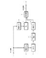
次に、この発明の一実施形態における学習、すなわち予測係数を決定する処理について図8を参照して説明する。入力端子20を介して、画像情報変換の結果として生成されるべき画像と同一の信号形式を有する画像(教師画像と称される)内の画素を全て含む画像が供給される。この発明の一実施形態は、50Hz画像を100Hz画像に変換するものなので、100Hzプログレッシブ画像が入力端子20を介して垂直位相シフトフィルタ21および遅延回路28に供給される。垂直位相シフトフィルタ21は、図4〜図7を参照して上述したような画素位置関係の何れを前提として学習を行うかに応じた処理を行う(これについては後述する)。
【0035】
垂直位相シフトフィルタ21の出力が時間間引きフィルタ22に供給される。時間間引きフィルタ22は、垂直位相シフトフィルタ21の出力に対して、時間方向に平滑化する処理を施すことにより、50Hzインターレース画素位置に画素を生成する。このようにして、SD画像と同一の信号形式(すなわち50Hzインターレース画像)を生成することができる。かかる画像は生徒画像と称される。生徒画像が領域切り出し回路23、26に供給される。
【0036】
領域切り出し回路23は、図1中の領域切り出し回路2と同一の処理を行う。すなわち、領域切り出し回路23は、供給される生徒画像から、領域切り出し回路2によって切り出されるものと同一の画素領域をクラスタップとして切り出し、切り出したクラスタップのデータをADRC回路24に供給する。ADRC回路24は、供給されるデータに図1中のADRC回路3と同一の処理を施す。すなわち、上述の式(1)に示したような演算を行うことにより、例えば8ビットを単位とするデータから2ビットを単位とする再量子化コードを形成する。形成された再量子化コードがパターン圧縮データとしてクラスコード発生回路25に供給する。
【0037】
クラスコード発生回路25は、図1中のクラスコード発生回路3と同一の処理を行う。すなわち、クラスコード発生回路25は、ADRC回路24の出力に基づいて上述の式(2)に示したような演算を行うことにより、クラスコードを発生する。クラスコード発生回路25の出力は、正規方程式加算回路29に供給される。一方、領域切り出し回路26は、図1中の領域切り出し回路6と同一の処理を行う。すなわち、領域切り出し回路26は、供給される画像信号から、領域切り出し回路6によって切り出されるものと同一の画素領域を予測タップとして切り出し、切り出した予測タップのデータを遅延回路27に供給する。遅延回路27は、供給されるデータを一旦保持し、その後、正規方程式加算回路29に供給する。
【0038】
また、遅延回路28は、供給される100Hzプログレッシブ画像を一旦保持し、その後、正規方程式加算回路29に供給する。遅延回路28および29により、算処理を行ために好適なタイミングで、正規方程式加算回路29が領域切り出し回路26の出力および100Hzプログレッシブ画像を供給されることが担保される。
【0039】
正規方程式加算回路29は、遅延回路27から供給されるクラスタップのデータ、遅延回路25から供給されるクラスコード、および遅延回路28から供給される100Hzプログレッシブ画像に基づいて、後述するような正規方程式のデータを算出する。ここで、正規方程式加算回路29は、100Hzプログレッシブ画像から教師画像を構成するデータを抽出し、抽出したデータに基づく演算処理を行う。算出されるデータは、予測係数決定回路30に供給される。予測係数決定回路30は、供給されるデータに基づいて正規方程式を解くための演算を行う。かかる演算の結果として算出された予測係数はメモリ31に供給される。図1を参照して上述した構成による処理を行うに先立ち、メモリ31の記憶内容が係数メモリ5にロードされる。
【0040】
予測係数を算出するための演算処理について説明する。以下の説明では、予測タップとして切り出される画素数を一般化してnとする。すなわち、x1 ,x2 ,‥‥,xn を予測タップとする場合、フィールド倍速画像中の画素レベルyが次の式(4)に従って計算されるとする。
【0041】
y=w1 ×x1 +w2 ×x2 +‥‥+wn ×xn (4)
学習前は、予測係数w1 ,‥‥,wn が未定係数である。学習は、クラス毎に複数の画像データについて行う。画像データの種類数をmと表記する場合、式(4)から、以下の式(5)が設定される。
【0042】
yk =w1 ×xk1+w2 ×xk2+‥‥+wn ×xkn (5)
(k=1,2,‥‥,m)
m>nの場合には、w1 ,‥‥,wn は一意に決まらないので、誤差ベクトルeの要素ek を以下の式(6)で定義して、式(7)によって定義される誤差ベクトルeを最小とするように予測係数を定めるようにする。すなわち、いわゆる最小2乗法によって予測係数を一意に定める。
【0043】
ek =yk −{w1 ×xk1+w2 ×xk2+‥‥+wn ×xkn} (6)
(k=1,2,‥‥m)
【0044】
【数2】
式(7)のe2 を最小とする予測係数を求めるための実際的な計算方法としては、e2 を予測係数wi (i=1,2‥‥)で偏微分し(式(8))、iの各値について偏微分値が0となるように各予測係数wi を決定すれば良い。
【0046】
【数3】
式(8)から各予測係数wi を決定する具体的な手順について説明する。式(9)、(10)のようにXji,Yi を定義すると、式(8)は、式(11)の行列式の形に書くことができる。
【0048】
【数4】
【数5】
【数6】
式(11)が一般に正規方程式と呼ばれるものである。正規方程式加算回路29は、供給されるデータに基づいて式(9)、(10)に示すような演算を行うことにより、Xji,Yi (i=1,2,‥‥,n)をそれぞれ計算する。予測係数決定回路30は、掃き出し法等の一般的な行列解法に従って正規方程式(11)を解くことにより、予測係数wi (i=1,2,‥‥,n)を算出する。以上のような処理の結果として、統計的に最も真値に近い推定値を各クラス毎のフィールド倍速データyとして推定するための予測係数が算出される。
【0052】
この発明は、上述したような学習を、複数の画素位置関係の各々について選択的に行うようにしたものである。この発明の一実施形態では、図4〜図7を参照して上述した4種類の画素位置関係の何れに対しても、対応する予測係数を計算できるように構成されている。まず、図5および図7を参照して上述したような画素位置関係においては、入力する50Hz画像内の画素と、創造すべき100Hz画像内の画素との垂直方向の画素位置がずれている。かかる位置関係に対応した学習を行う際には、垂直間位相シフトフィルタ21は、供給される100Hzプログレッシブ画像に対して垂直方向の位相シフトを行う。
【0053】
一方、図4および図6を参照して上述したような画素位置関係においては、入力する50Hz画像内の画素と、創造すべき100Hz画像内の画素との垂直方向の画素位置が一致している。かかる位置関係に対応した学習を行う際には、垂直間引きフィルタ21は、位相シフトは行わず、供給される100Hzプログレッシブ画像をそのまま出力する。
【0054】
上述したようにして、画像情報変換の対象および結果である、50Hz画像および100Hz画像の間の複数種類の画素位置関係の内で、画像情報変換の結果として生成されるべき100Hz画像のとしてより高品質の画像が生成されるような学習を行うことが可能となる。
【0055】
また、予測係数を保持するためのメモリ容量等のハードウエア的な制約、ラインフリッカが許容されるか否か等の用途等に係る条件等に関連して最も好適な画素位置関係に対応する学習を選択的に行うことができる。これにより、より好適な画素位置関係を前提とするクラス分類適応処理を適用してフィールド倍速変換等の画像情報変換を行うことが可能となるので、総合的な変換性能を向上させることができる。
【0056】
上述したこの発明の一実施形態は、50Hz画像を100Hz画像に変換するフィールド倍速変換を行うものである。これに対して、学習時に、例えば垂直方向の位相シフト等を必要に応じて行うことによって教師画像、或いは生徒画像を生成することにより、インターレース画像をプログレッシブ画像に変換する、或いはSD画像をHD(High Definition) 画像に変換する等の画像情報変換を行う場合等においても、この発明を適用することができる。すなわち、この発明は、ディジタル画像を、より画素数の多いディジタル画像に変換する画像情報変換全般において有効である。
【0057】
また、この発明の一実施形態は、100Hzのプログレッシブ画像と50Hzのインターレース画像との間で学習を行うものであるが、学習に係る画像の組み合わせはこれに限定されるものではない。例えば、50Hzのプログレッシブ画像と25Hzのインターレース画像との間で学習を行うようにしても良いし、60Hzのプログレッシブ画像と30Hzのインターレース画像との間で学習を行うようにしても良い。
【0058】
また、上述したこの発明の一実施形態では、50Hz画像等の入力画像の空間波形を少ないビット数でパターン化するためにADRCを行うようにしている。これに対して、時空間内における画像パターンを少ないクラスで表現することに資するような情報圧縮方法であれば、ADRC以外の方法を用いるようにしても良い。例えば、DPCM(Differential Pulse Code Modulation)や、VQ(Vector Quantization )等の方法を用いるようにしても良い。
【0059】
この発明は、上述したこの発明の一実施形態に限定されるものでは無く、この発明の主旨を逸脱しない範囲内で様々な変形や応用が可能である。
【0060】
【発明の効果】
この発明によれば、生徒画像と教師画像との複数種類の組合わせの内から何れかの組合わせを選択し、選択した組合わせの下で学習を行うことによって決定される予測係数を使用して予測演算を行うことができる。
【0061】
このため、画像情報変換の結果としてより高品質の画像が生成されるような学習を行うことが可能となる。
【0062】
また、予測係数を保持するためのメモリ容量等のハードウエア的な制約、ラインフリッカが許容されるか否か等の用途等に係る条件等に関連して最も好適な画素位置関係に対応する学習を行うことが可能となる。
【0063】
また、生徒画像と教師画像との組合わせによって時間方向或いは空間方向の対称性が異なることに起因して、予測係数の種類数も異なるので、予測係数として記憶されるべきデータ量は、選択される生徒画像と教師画像との組合わせによって異なる。このため、この発明を適用することにより、装置の仕様等において許容される予測係数用のメモリの容量等の条件により適合する画像情報変換を行うことができる。
【図面の簡単な説明】
【図1】この発明の一実施形態における画像情報変換に係る構成の一例を示すブロック図である。
【図2】クラスタップのタップ構造の一例を示す略線図である。
【図3】予測タップのタップ構造の一例を示す略線図である。
【図4】本願出願人の先の提案に係る画像情報変換における画素位置関係について説明するための略線図である。
【図5】この発明の一実施形態において用いることができる画素位置関係の一例について説明するための略線図である。
【図6】この発明の一実施形態において用いることができる画素位置関係の他の例について説明するための略線図である。
【図7】この発明の一実施形態において用いることができる画素位置関係のさらに他の一例について説明するための略線図である。
【図8】この発明の一実施形態における学習について説明するためのブロック図である。
【符号の説明】
21・・・垂直位相シフトフィルタ[0001]
BACKGROUND OF THE INVENTION
The present invention relates to an image information conversion apparatus and conversion method for converting an input digital image signal into a digital image signal having a larger number of pixels.
[0002]
[Prior art]
Conventionally, as a scanning method for a television receiver, an interlace scanning method in which scanning is performed by skipping every other horizontal scanning line (line) has been most widely adopted. In the interlace scanning method, one frame is formed by two fields of an odd field obtained by scanning odd lines and an even field obtained by scanning even lines.
[0003]
The interlace scanning method is adopted as a television standard method in various countries around the world. For example, in European television broadcasting, an interlace scanning method with a field frequency of 50 Hz is used.
[0004]
[Problems to be solved by the invention]
In a television receiver using an interlace scanning method with a field frequency of 50 Hz, there is a problem that flicker called surface flicker occurs over a wide range of the display screen. The surface flicker occurs due to the fact that each line is displayed at every predetermined time interval because it takes a predetermined time to switch from the odd field to the even field in the interlace scanning method.
[0005]
As a method for coping with such a problem, a field double speed process for generating an image signal of, for example, 100 Hz by generating an interpolation field by a median filter based on an input (for example, 50 Hz SD (Standard Definition)) image is known. ing. This method uses an intermediate pixel value as a pixel value of an interpolated pixel in, for example, three pixels close to the interpolated pixel in a field including the interpolated pixel and in a field preceding the field including the interpolated pixel. It is what.
[0006]
However, in such a method, when the SD image to be subjected to the interpolation process is a still image, unnatural distortion occurs in an image region having a high vertical resolution. In addition, when the SD image to be interpolated is a moving image, the pixel value of the pixel one field before may be selected as the pixel value of the interpolation pixel. When such a selection is made, There was a problem that unnatural movement occurred.
[0007]
In order to solve such a problem, the applicant of the present application has proposed a method of converting an input image into a field double speed image by performing a classification adaptation process. However, in such a method, there is a possibility that the conversion performance partially varies depending on the positional relationship between the pixel in the image to be generated and the pixel in the SD image, and as a result, improvement in the image quality of the entire field double speed image may be hindered. there were.
[0008]
Accordingly, an object of the present invention is to perform image information conversion such as a field double-speed image by performing processing assuming a plurality of types of pixel positional relationships between pixels in an image to be generated and pixels in an SD image. It is an object of the present invention to provide an image information conversion apparatus and conversion method capable of improving the image quality of an image generated as a result of the above.
[0009]
[Means for Solving the Problems]
The invention of
[0010]
Claim 4 The invention of Interlaced scanning By generating a new field between the fields of the input digital image signal, the number of fields greater than the number of fields of the input digital image signal Interlaced scanning In an image information conversion method for forming an output digital image signal, a first image cutout step of cutting out a plurality of image data around a target pixel to be processed from the input digital image signal, and a plurality of cutouts by the first image cutout step Detecting a level distribution of each of the image data, determining a class to which the target pixel belongs from the detected level distribution, outputting class detection information expressing the determined class, and a target pixel from the input digital image signal A second image cut-out step for cutting out a plurality of image data around the image, and a prediction coefficient determined in advance corresponding to each of the classes and storing an output digital image signal, from among the stored prediction coefficients , Output the prediction coefficient corresponding to the class detection information from the class detection step A product-sum operation is performed on the plurality of pieces of image data cut out by the number storage step, the second image cut-out step, and the prediction coefficient supplied from the coefficient storage step, and a predicted value of the image data of the output digital image signal is generated. A prediction coefficient is obtained by learning in advance for each class and stored, and learning is performed by calculating the pixel position of the input digital image signal. In contrast, an output digital image signal having a first positional relationship that includes a field that matches the field of the input digital image signal in the time direction and that has a pixel position in the vertical direction that matches the input digital image signal; And an output digital image signal having a second positional relationship in which the pixel position is symmetrical in the vertical direction with the pixel position of the input digital image signal as the center, and a field of the input digital image signal The field is symmetrical in the time direction and the output digital image signal in the third positional relationship in which the pixel position in the vertical direction coincides with the input digital image signal and the field of the input digital image signal is in the time direction. And the pixel position of the input digital image signal Pixel position as the center of the fourth positional relation of symmetry in the vertical direction Output digital image signal Of the output digital image signal of the first, second, third and fourth positional relationships One from the inside Position-related output digital image signal Select The input digital image signal is the pixel of the teacher image signal in the same signal format as the selected output digital image signal. To the pixel position of conversion A digital image signal in which the number of fields per unit time of the output digital image signal is converted so as to be the same as the input digital image signal, Generated From digital image signal chosen Output digital image signal Pixel value of Generate a Do Sometimes generated Be done Pixel value and teacher In order to minimize the error from the true value of the pixel at the corresponding position of the image signal, The prediction factor This is an image information conversion method that is a process to be obtained.
[0011]
According to the invention as described above, a prediction coefficient can be generated using a combination more suitable for desired image information conversion among a plurality of types of combinations of a student image signal and a teacher image signal. .
[0012]
DETAILED DESCRIPTION OF THE INVENTION
Hereinafter, an embodiment of the present invention will be described with reference to the drawings. FIG. 1 shows an example of a configuration relating to image information conversion in one embodiment of the present invention. An image signal obtained by digitizing a 50 Hz interlaced image in the PAL system is supplied to the
[0013]
The class code generation circuit 4 generates a class code indicating a class corresponding to a pattern in space-time based on the supplied code value. The generated class code is supplied to the coefficient memory 5. The coefficient memory 5 is determined in advance as will be described later. Forecast Coefficient of measurement set Is stored corresponding to the class code.
[0014]
On the other hand, the region cutout circuit 6 cuts out a predetermined pixel region from the supplied 50 Hz interlaced image as a prediction tap, and supplies the cutout tap data to the delay circuit 7. The delay circuit 7 once holds the supplied data, and supplies the held data to the estimation arithmetic circuit 8 at an appropriate timing. Thereby, the timing at which the prediction tap data is supplied to the estimation calculation circuit 8 and the timing at which the prediction coefficient is supplied from the coefficient memory 5 to the estimation calculation circuit 8 are matched. The estimation operation circuit 8 generates a 100 Hz image as a field double speed image by performing an operation based on the output of the delay circuit 7 and the output of the coefficient memory 5. The generated 100 Hz image is displayed on a display device such as a television receiver (not shown) via the output terminal 9. etc To be supplied.
[0015]
Hereinafter, processing by each component will be described in detail. A typical example of the tap structure of the class tap cut out by the
[0016]
The
[0017]
DR = MAX-
Q = [(L−MIN + 0.5) × 2 n / DR] (1)
Here, DR is a dynamic range within the region. Also, n is the number of bits allocated, and for example, n = 2 can be set. L is the data level of the pixels in the area, and Q is the requantization code. However, the brackets ([...]) Indicate truncation processing.
[0018]
K as shown in FIG. 1 ~ K 7 When the tap structure of class taps consisting of 7 pixels is used, the 7 requantization codes q corresponding to each pixel are obtained by the processing as described above. 1 ~ Q 7 Is the output of the
[0019]
[Expression 1]
Here, n is the number of pixels in the class tap, and n = 7 in the tap structure of the class tap as shown in FIG. Moreover, as a value of p, it can be set as p = 2, for example.
[0021]
A general example of the tap structure of the prediction tap cut out by the area cutout circuit 6 is shown in FIG. Here, the horizontal direction shows the transition of time. That is, # (k−2), # (k−1),..., # (K + 2) indicate fields at time points k−2, k−1,. The vertical direction indicates the vertical direction in each field. In this example, k 1 ~ K 7 These seven pixels are taken as prediction taps.
[0022]
hd '= w 1 X 1 + W 2 X 2 + ... + w n X n (3)
Where x 1 , ..., x n Is the pixel data of each prediction tap, and w 1 , ..., w n Is each prediction coefficient set It is.
[0023]
hd '= w 1 X 1 + W 2 X 2 + ... + w n X n (3)
Where x 1 , ..., x n Is the pixel data of each prediction tap, and w 1 , ..., w n Is each prediction coefficient.
[0024]
As described above, when the field double speed image is generated by the class classification adaptive process, the field double speed image can be generated with higher accuracy than when the SD image data is simply interpolated. Note that the prediction coefficient is determined by processing as will be described later in accordance with the relationship between the pixel position in the SD image data and the pixel position in the field double speed image to be generated.
[0025]
Next, the conversion performance according to the positional relationship between the pixel position in the 50 Hz image as the SD image and the pixel position in the 100 Hz image as the field double speed image will be described. First, FIG. 4 shows an example of the relationship between the pixel position of the field to be created and the pixel position of the prediction tap in the previous proposal (see 9800237506) related to the field double speed processing by the applicant of the present application. In this case, the created 100 Hz pixel m 1 , M 2 , M Three , M Four Of which m 1 Is in a position that coincides with the 50 Hz pixel in time and space, m 1 The conversion performance related to the creation of is very good.
[0026]
In contrast, m 2 And m Four Has a large temporal separation from the 50 Hz pixel. 2 And m Four The conversion performance related to the creation of 1 There was a problem that it was inferior to the conversion performance related to the creation. In general, the quality of an image as a whole tends to be strongly influenced by the most deteriorated portion of the entire image. For this reason, in order to improve the image quality of the entire image, it is not preferable that the conversion performance varies greatly depending on the positional relationship of the pixels.
[0027]
Also, 100Hz pixel m 2 And m Four Can be created by using the same prediction coefficients when using temporal symmetry. In contrast, 100 Hz pixel m 1 And m Three In order to create each, it is necessary to use a separate prediction coefficient. That is, in the example shown in FIG. 4, three types of prediction coefficients are required. For this reason, since the scale of hardware becomes large, it may become a problem especially when the scale of hardware is restricted.
[0028]
Therefore, the present invention enables selection of a more appropriate pixel positional relationship between the pixels in the SD image and the pixels in the field double speed image. Hereinafter, in addition to the example shown in FIG. 4, one example of the pixel positional relationship that can be used in one embodiment of the present invention, another example, and another example shown in FIG. 5, FIG. 6, and FIG. explain.
[0029]
When performing field double speed conversion using the example of the pixel position relationship shown in FIG. 1 Has the highest prediction accuracy of m Three Has the next highest prediction accuracy, m 2 And m Four Has the lowest prediction accuracy. The image quality of the entire image obtained by the conversion is m 2 And m Four Is greatly affected by the prediction accuracy. Further, as described above, a total of three types of prediction coefficients are required. In this pixel position relationship, line flicker is not emphasized.
[0030]
When performing field double speed conversion using another example of the pixel position relationship shown in FIG. 1 , M 2 , M Three , M Four The prediction accuracy differs for each of the four types of pixels. However, the variation is small compared to the example shown in FIG. 4, and the degree of variation is substantially the same as the example shown in FIG. M 1 And m Three Can be made common by using the symmetry in the time direction. Furthermore, m 2 And m Four Is created by using the symmetry of the space (vertical) direction. Person in charge Numbers can be shared. Therefore, two types of prediction coefficients are required in total for the four types of pixels to be created. In this case, line flicker is not emphasized.
[0031]
When performing field double speed conversion using another example of the pixel position relationship shown in FIG. 1 , M 2 , M Three , M Four The prediction accuracy differs for each of the four types of pixels. However, the variation is small compared to the example shown in FIG. 4, and the degree of variation is substantially the same as the example shown in FIG. M 1 And m Three Can be made common by using the symmetry in the time direction. Furthermore, m 2 And m Four Can be made common by using the symmetry in the spatial (vertical) direction. Therefore, two types of prediction coefficients are required in total for the four types of pixels to be created. In this case, line flicker is not emphasized.
[0032]
When performing field double speed conversion using still another example of the pixel positional relationship shown in FIG. 1 , M 2 , M Three , M Four The prediction accuracy is the same for each of the four types of pixels, and there is no variation depending on the pixel position of the prediction accuracy. Also, by using the symmetry in the time direction / the symmetry in the space (vertical) direction, m 1 ~ M Four It is possible to share all the prediction coefficients. Therefore, all of the four types of pixels to be created can be created under one type of prediction coefficient. In this case, line flicker may be emphasized.
[0033]
Considering the characteristics of each example of the pixel position relationship as described above, it is related to hardware restrictions such as memory capacity for holding the prediction coefficient, usage such as whether line flicker is allowed, etc. By selecting the most suitable pixel positional relationship according to conditions and the like, it is possible to improve the overall conversion performance.
[0034]
Next, learning in one embodiment of the present invention, that is, processing for determining a prediction coefficient will be described with reference to FIG. An image including all pixels in an image (referred to as a teacher image) having the same signal format as the image to be generated as a result of image information conversion is supplied via the
[0035]
The output of the vertical
[0036]
The
[0037]
The class code generation circuit 25 performs the same processing as the class
[0038]
The
[0039]
The normal
[0040]
A calculation process for calculating the prediction coefficient will be described. In the following description, the number of pixels cut out as a prediction tap is generalized to n. That is, x 1 , X 2 , ..., x n Is a prediction tap, the pixel level y in the field double speed image is calculated according to the following equation (4).
[0041]
y = w 1 X 1 + W 2 X 2 + ... + w n X n (4)
Before learning, prediction coefficient w 1 , ..., w n Is an undetermined coefficient. Learning is performed for a plurality of image data for each class. When the number of types of image data is expressed as m, the following equation (5) is set from equation (4).
[0042]
y k = W 1 X k1 + W 2 X k2 + ... + w n X kn (5)
(K = 1, 2,..., M)
If m> n, w 1 , ..., w n Is not uniquely determined, the element e of the error vector e k Is defined by the following equation (6), and the prediction coefficient is determined so as to minimize the error vector e defined by equation (7). That is, the prediction coefficient is uniquely determined by a so-called least square method.
[0043]
e k = Y k -{W 1 X k1 + W 2 X k2 + ... + w n X kn } (6)
(K = 1, 2, ... m)
[0044]
[Expression 2]
E in equation (7) 2 As a practical calculation method for obtaining the prediction coefficient that minimizes 2 Prediction coefficient w i (i = 1, 2...) is partially differentiated (equation (8)), and each prediction coefficient w i You just have to decide.
[0046]
[Equation 3]
From Equation (8), each prediction coefficient w i A specific procedure for determining the will be described. X as in equations (9) and (10) ji , Y i (8) can be written in the form of the determinant of equation (11).
[0048]
[Expression 4]
[Equation 5]
[Formula 6]
Equation (11) is generally called a normal equation. The normal
[0052]
In the present invention, learning as described above is selectively performed for each of a plurality of pixel positional relationships. In one embodiment of the present invention, a prediction coefficient corresponding to any of the four types of pixel positional relationships described above with reference to FIGS. 4 to 7 can be calculated. First, in the pixel position relationship as described above with reference to FIGS. 5 and 7, the pixel position in the vertical direction is shifted between the pixel in the input 50 Hz image and the pixel in the 100 Hz image to be created. When learning corresponding to such a positional relationship is performed, the inter-vertical
[0053]
On the other hand, in the pixel positional relationship as described above with reference to FIGS. 4 and 6, the pixel position in the vertical direction of the input pixel in the 50 Hz image and the pixel in the 100 Hz image to be created are the same. . When performing learning corresponding to such a positional relationship, the vertical thinning
[0054]
As described above, among the plurality of types of pixel positional relationships between the 50 Hz image and the 100 Hz image, which are objects and results of the image information conversion, higher as a 100 Hz image to be generated as a result of the image information conversion. It is possible to perform learning such that a quality image is generated.
[0055]
Also, learning corresponding to the most suitable pixel positional relationship in relation to hardware restrictions such as memory capacity for holding prediction coefficients, conditions such as whether or not line flicker is allowed, etc. Can be selectively performed. As a result, it is possible to perform image information conversion such as field double speed conversion by applying a class classification adaptation process that presupposes a more preferable pixel position relationship, and thus it is possible to improve the overall conversion performance.
[0056]
One embodiment of the present invention described above performs field double speed conversion for converting a 50 Hz image into a 100 Hz image. On the other hand, at the time of learning, for example, a teacher image or a student image is generated by performing vertical phase shift or the like as necessary, thereby converting an interlaced image into a progressive image, or an SD image as an HD ( (High Definition) The present invention can also be applied to image information conversion such as conversion to an image. That is, the present invention is effective in general image information conversion for converting a digital image into a digital image having a larger number of pixels.
[0057]
In addition, although one embodiment of the present invention performs learning between a 100 Hz progressive image and a 50 Hz interlaced image, the combination of images related to learning is not limited to this. For example, learning may be performed between a 50 Hz progressive image and a 25 Hz interlaced image, or learning may be performed between a 60 Hz progressive image and a 30 Hz interlaced image.
[0058]
In the embodiment of the present invention described above, ADRC is performed to pattern the spatial waveform of an input image such as a 50 Hz image with a small number of bits. On the other hand, if it is an information compression method that contributes to expressing an image pattern in space-time with a small number of classes, a method other than ADRC is used In You may do it. For example, a method such as DPCM (Differential Pulse Code Modulation) or VQ (Vector Quantization) may be used.
[0059]
The present invention is not limited to the above-described embodiment of the present invention, and various modifications and applications can be made without departing from the gist of the present invention.
[0060]
【The invention's effect】
According to the present invention, a prediction coefficient determined by selecting any combination from among a plurality of combinations of student images and teacher images and performing learning under the selected combination is used. Predictive calculations can be performed.
[0061]
Therefore, it is possible to perform learning such that a higher quality image is generated as a result of the image information conversion.
[0062]
Also, learning corresponding to the most suitable pixel positional relationship in relation to hardware restrictions such as memory capacity for holding prediction coefficients, conditions such as whether or not line flicker is allowed, etc. Can be performed.
[0063]
In addition, since the number of types of prediction coefficients varies depending on the combination of the student image and the teacher image, the number of types of prediction coefficients varies, so the amount of data to be stored as the prediction coefficient is selected. It depends on the combination of the student image and the teacher image. For this reason, by applying the present invention, it is possible to perform image information conversion that is more suitable for conditions such as the capacity of the memory for prediction coefficients allowed in the specifications of the apparatus.
[Brief description of the drawings]
FIG. 1 is a block diagram illustrating an example of a configuration related to image information conversion according to an embodiment of the present invention.
FIG. 2 is a schematic diagram illustrating an example of a tap structure of a class tap.
FIG. 3 is a schematic diagram illustrating an example of a tap structure of a prediction tap.
FIG. 4 is a schematic diagram for explaining a pixel position relationship in image information conversion according to the previous proposal of the applicant of the present application.
FIG. 5 is a schematic diagram for explaining an example of a pixel position relationship that can be used in an embodiment of the present invention;
FIG. 6 is a schematic diagram for explaining another example of the pixel positional relationship that can be used in one embodiment of the present invention.
FIG. 7 is a schematic diagram for explaining yet another example of a pixel positional relationship that can be used in an embodiment of the present invention.
FIG. 8 is a block diagram for explaining learning in an embodiment of the present invention.
[Explanation of symbols]
21 ... Vertical phase shift filter
Claims (4)
上記入力ディジタル画像信号から処理対象の注目画素の周辺の複数の画像データを切り出す第1の画像切り出し手段と、
上記第1の画像切り出し手段によって切り出される上記複数の画像データの各々のレベル分布を検出し、検出したレベル分布から上記注目画素が属するクラスを決定し、決定したクラスを表現するクラス検出情報を出力するクラス検出手段と、
上記入力ディジタル画像信号から上記注目画素の周辺の複数の画像データを切り出す第2の画像切り出し手段と、
上記クラスのそれぞれに対応して予め決定され、上記出力ディジタル画像信号を推定するための予測係数を記憶し、記憶した予測係数の内から、上記クラス検出手段からの上記クラス検出情報に対応する予測係数を出力する係数記憶手段と、
上記第2の画像切り出し手段によって切り出される上記複数の画像データと、上記係数記憶手段から供給される予測係数との積和演算を行い、上記出力ディジタル画像信号の画像データの予測値を生成する演算処理手段とを有し、
上記予測係数は、上記クラス毎に予め学習によって求められて上記係数記憶手段に記憶され、
上記学習は、
上記入力ディジタル画像信号の画素位置に対して、上記入力ディジタル画像信号のフィールドと時間方向に一致するフィールドを含み、且つ上記入力ディジタル画像信号と垂直方向の画素位置が一致する第1の位置関係の出力ディジタル画像信号と、上記入力ディジタル画像信号のフィールドと時間方向に一致するフィールドを含み、且つ上記入力ディジタル画像信号の画素位置を中心として画素位置が垂直方向に対称となる第2の位置関係の出力ディジタル画像信号と、上記入力ディジタル画像信号のフィールドを中心としてフィールドが時間方向に対称となり、且つ上記入力ディジタル画像信号と垂直方向の画素位置が一致する第3の位置関係の出力ディジタル画像信号と、上記入力ディジタル画像信号のフィールドを中心としてフィールドが時間方向に対称となり、且つ上記入力ディジタル画像信号の画素位置を中心として画素位置が垂直方向に対称となる第4の位置関係の出力ディジタル画像信号とからなり、
上記第1、第2、第3、および第4の位置関係の出力ディジタル画像信号の内から1つの位置関係の出力ディジタル画像信号を選択し、上記選択された出力ディジタル画像信号と同一の信号形式の教師画像信号の画素を、上記入力ディジタル画像信号の画素位置へ変換し、
上記変換された出力ディジタル画像信号の単位時間当たりのフィールド数を、上記入力ディジタル画像信号と同一となるように変換したディジタル画像信号を生成し、
上記積和演算によって、上記生成されたディジタル画像信号から上記選択された出力ディジタル画像信号の画素値を生成する時に、生成される画素値と上記教師画像信号の対応する位置の画素の真値との誤差を最小にするように、上記予測係数を求める処理である画像情報変換装置。 In an image information conversion apparatus for forming an interlace scanning output digital image signal having a number of fields larger than the number of fields of the input digital image signal by generating a new field between fields of the interlace scanning input digital image signal.
First image cutout means for cutting out a plurality of image data around a target pixel to be processed from the input digital image signal;
The level distribution of each of the plurality of image data cut out by the first image cutout means is detected, the class to which the target pixel belongs is determined from the detected level distribution, and class detection information representing the determined class is output. Class detection means to
Second image cutout means for cutting out a plurality of image data around the pixel of interest from the input digital image signal;
Prediction corresponding to each of the classes, a prediction coefficient for estimating the output digital image signal is stored, and a prediction corresponding to the class detection information from the class detection means is stored out of the stored prediction coefficients Coefficient storage means for outputting a coefficient;
An operation for performing a product-sum operation on the plurality of image data cut out by the second image cut-out means and a prediction coefficient supplied from the coefficient storage means to generate a predicted value of the image data of the output digital image signal Processing means,
The prediction coefficient is obtained by learning in advance for each class and stored in the coefficient storage means.
The above learning
A first positional relationship that includes a field that coincides with the field of the input digital image signal in the time direction with respect to the pixel position of the input digital image signal and that has a pixel position in the vertical direction that coincides with the input digital image signal. A second positional relationship that includes an output digital image signal and a field that coincides with the field of the input digital image signal in the time direction, and that the pixel position is symmetrical in the vertical direction about the pixel position of the input digital image signal. An output digital image signal, and an output digital image signal having a third positional relationship in which the field is symmetric in the time direction around the field of the input digital image signal and the pixel position in the vertical direction coincides with the input digital image signal; The field centered on the input digital image signal field De becomes symmetrical in the time direction, and consists of a output digital image signal of the fourth positional relationship pixel position as the center pixel position of the input digital image signal is symmetrical in the vertical direction,
An output digital image signal having one positional relationship is selected from the output digital image signals having the first, second, third, and fourth positional relationships, and the same signal format as the selected output digital image signal Converting the pixel of the teacher image signal into the pixel position of the input digital image signal ,
Generating a digital image signal in which the number of fields per unit time of the converted output digital image signal is converted to be the same as the input digital image signal;
By the product-sum operation, and a true value of the pixel at the corresponding position of at, the pixel values generated and the teacher image signal to generate a pixel value of the selected output digital image signal from a digital image signal generated as above An image information conversion apparatus which is a process for obtaining the prediction coefficient so as to minimize the error.
単位時間当たりのフィールド数が上記入力ディジタル画像信号の2倍となるような上記出力ディジタル画像信号を生成する請求項1に記載の画像情報変換装置。The arithmetic processing means is:
2. The image information conversion apparatus according to claim 1, wherein the output digital image signal is generated so that the number of fields per unit time is twice that of the input digital image signal.
上記出力ディジタル画像信号の画素に対して垂直位相のずれを生じさせ、上記入力ディジタル画像信号の画素位置へ変換する垂直位相シフト手段を有する請求項1に記載の画像情報変換装置。In the above learning,
2. The image information conversion apparatus according to claim 1, further comprising vertical phase shift means for generating a vertical phase shift with respect to a pixel of the output digital image signal and converting the pixel to a pixel position of the input digital image signal .
上記入力ディジタル画像信号から処理対象の注目画素の周辺の複数の画像データを切り出す第1の画像切り出しステップと、
上記第1の画像切り出しステップによって切り出される上記複数の画像データの各々のレベル分布を検出し、検出したレベル分布から上記注目画素が属するクラスを決定し、決定したクラスを表現するクラス検出情報を出力するクラス検出ステップと、
上記入力ディジタル画像信号から上記注目画素の周辺の複数の画像データを切り出す第2の画像切り出しステップと、
上記クラスのそれぞれに対応して予め決定され、上記出力ディジタル画像信号を推定するための予測係数を記憶し、記憶した予測係数の内から、上記クラス検出ステップからの上記クラス検出情報に対応する予測係数を出力する係数記憶ステップと、
上記第2の画像切り出しステップによって切り出される上記複数の画像データと、上記係数記憶ステップから供給される予測係数との積和演算を行い、上記出力ディジタル画像信号の画像データの予測値を生成する演算処理ステップとを有し、
上記予測係数は、上記クラス毎に予め学習によって求められて記憶され、
上記学習は、
上記入力ディジタル画像信号の画素位置に対して、上記入力ディジタル画像信号のフィールドと時間方向に一致するフィールドを含み、且つ上記入力ディジタル画像信号と垂直方向の画素位置が一致する第1の位置関係の出力ディジタル画像信号と、上記入力ディジタル画像信号のフィールドと時間方向に一致するフィールドを含み、且つ上記入力ディジタル画像信号の画素位置を中心として画素位置が垂直方向に対称となる第2の位置関係の出力ディジタル画像信号と、上記入力ディジタル画像信号のフィールドを中心としてフィールドが時間方向に対称となり、且つ上記入力ディジタル画像信号と垂直方向の画素位置が一致する第3の位置関係の出力ディジタル画像信号と、上記入力ディジタル画像信号のフィールドを中心としてフィールドが時間方向に対称となり、且つ上記入力ディジタル画像信号の画素位置を中心として画素位置が垂直方向に対称となる第4の位置関係の出力ディジタル画像信号とからなり、
上記第1、第2、第3、および第4の位置関係の出力ディジタル画像信号の内から1つの位置関係の出力ディジタル画像信号を選択し、上記選択された出力ディジタル画像信号と同一の信号形式の教師画像信号の画素を、上記入力ディジタル画像信号の画素位置へ変換し、
上記変換された出力ディジタル画像信号の単位時間当たりのフィールド数を、上記入力ディジタル画像信号と同一となるように変換したディジタル画像信号を生成し、
上記積和演算によって、上記生成されたディジタル画像信号から上記選択された出力ディジタル画像信号の画素値を生成する時に、生成される画素値と上記教師画像信号の対応する位置の画素の真値との誤差を最小にするように、上記予測係数を求める処理である画像情報変換方法。 In an image information conversion method for forming an interlace scanning output digital image signal having a number of fields larger than the number of fields of the input digital image signal by generating a new field between fields of the interlace scanning input digital image signal.
A first image cutout step of cutting out a plurality of pieces of image data around a target pixel to be processed from the input digital image signal;
The level distribution of each of the plurality of image data cut out by the first image cut-out step is detected, the class to which the target pixel belongs is determined from the detected level distribution, and class detection information expressing the determined class is output. Class detection step to
A second image cutout step of cutting out a plurality of image data around the pixel of interest from the input digital image signal;
Prediction corresponding to each of the classes, a prediction coefficient for estimating the output digital image signal is stored, and a prediction corresponding to the class detection information from the class detection step is stored out of the stored prediction coefficients A coefficient storage step for outputting a coefficient;
An operation for performing a product-sum operation on the plurality of image data cut out by the second image cut-out step and a prediction coefficient supplied from the coefficient storage step to generate a predicted value of the image data of the output digital image signal Processing steps,
The prediction coefficient is obtained by learning in advance for each class and stored,
The above learning
A first positional relationship that includes a field that coincides with the field of the input digital image signal in the time direction with respect to the pixel position of the input digital image signal and that has a pixel position in the vertical direction that coincides with the input digital image signal. A second positional relationship that includes an output digital image signal and a field that coincides with the field of the input digital image signal in the time direction, and that the pixel position is symmetrical in the vertical direction about the pixel position of the input digital image signal. An output digital image signal, and an output digital image signal having a third positional relationship in which the field is symmetric in the time direction around the field of the input digital image signal and the pixel position in the vertical direction coincides with the input digital image signal; The field centered on the input digital image signal field De becomes symmetrical in the time direction, and consists of a output digital image signal of the fourth positional relationship pixel position as the center pixel position of the input digital image signal is symmetrical in the vertical direction,
An output digital image signal having one positional relationship is selected from the output digital image signals having the first, second, third, and fourth positional relationships, and the same signal format as the selected output digital image signal Converting the pixel of the teacher image signal into the pixel position of the input digital image signal ,
Generating a digital image signal in which the number of fields per unit time of the converted output digital image signal is converted to be the same as the input digital image signal;
By the product-sum operation, and a true value of the pixel at the corresponding position of at, the pixel values generated and the teacher image signal to generate a pixel value of the selected output digital image signal from a digital image signal generated as above An image information conversion method, which is a process for obtaining the prediction coefficient so as to minimize the error.
Priority Applications (1)
| Application Number | Priority Date | Filing Date | Title |
|---|---|---|---|
| JP12729499A JP4310847B2 (en) | 1999-05-07 | 1999-05-07 | Image information conversion apparatus and conversion method |
Applications Claiming Priority (1)
| Application Number | Priority Date | Filing Date | Title |
|---|---|---|---|
| JP12729499A JP4310847B2 (en) | 1999-05-07 | 1999-05-07 | Image information conversion apparatus and conversion method |
Publications (3)
| Publication Number | Publication Date |
|---|---|
| JP2000324497A JP2000324497A (en) | 2000-11-24 |
| JP2000324497A5 JP2000324497A5 (en) | 2006-04-06 |
| JP4310847B2 true JP4310847B2 (en) | 2009-08-12 |
Family
ID=14956413
Family Applications (1)
| Application Number | Title | Priority Date | Filing Date |
|---|---|---|---|
| JP12729499A Expired - Fee Related JP4310847B2 (en) | 1999-05-07 | 1999-05-07 | Image information conversion apparatus and conversion method |
Country Status (1)
| Country | Link |
|---|---|
| JP (1) | JP4310847B2 (en) |
Families Citing this family (1)
| Publication number | Priority date | Publication date | Assignee | Title |
|---|---|---|---|---|
| JP4277446B2 (en) * | 2000-12-26 | 2009-06-10 | ソニー株式会社 | INFORMATION SIGNAL PROCESSING DEVICE, INFORMATION SIGNAL PROCESSING METHOD, IMAGE SIGNAL PROCESSING DEVICE AND IMAGE DISPLAY DEVICE USING THE SAME |
-
1999
- 1999-05-07 JP JP12729499A patent/JP4310847B2/en not_active Expired - Fee Related
Also Published As
| Publication number | Publication date |
|---|---|
| JP2000324497A (en) | 2000-11-24 |
Similar Documents
| Publication | Publication Date | Title |
|---|---|---|
| JP4158232B2 (en) | Image information conversion device and image display device | |
| JP4696388B2 (en) | Information signal processing apparatus, information signal processing method, image signal processing apparatus and image display apparatus using the same, coefficient seed data generation apparatus, coefficient data generation apparatus, and information recording medium | |
| JP4147632B2 (en) | Image information conversion apparatus, image information conversion method, and television receiver | |
| JP4131048B2 (en) | Image information conversion apparatus, conversion method, and image display apparatus | |
| JP4168490B2 (en) | Motion determination device, method and image information conversion device | |
| JPH0795591A (en) | Digital picture signal processing unit | |
| JP4193233B2 (en) | Motion determination device, method and image information conversion device | |
| JP3946781B2 (en) | Image information conversion apparatus and method | |
| JP4310847B2 (en) | Image information conversion apparatus and conversion method | |
| JP3723995B2 (en) | Image information conversion apparatus and method | |
| JP4140091B2 (en) | Image information conversion apparatus and image information conversion method | |
| JP4470324B2 (en) | Image signal conversion apparatus and method | |
| JP4078719B2 (en) | Image information conversion apparatus, conversion method, and image display apparatus | |
| JP3480015B2 (en) | Apparatus and method for generating image data | |
| JP3800638B2 (en) | Image information conversion apparatus and method | |
| JP4123587B2 (en) | Image information processing apparatus and method | |
| JP4174891B2 (en) | Image information conversion apparatus and method | |
| JP4311166B2 (en) | Information signal processing apparatus and processing method, coefficient seed data generating apparatus and generating method used therefor, program for executing each method, and medium recording the program | |
| JP3653287B2 (en) | Image information conversion apparatus and image information conversion method | |
| JP3480011B2 (en) | Image information conversion device | |
| JP3587188B2 (en) | Digital image signal processing apparatus and processing method | |
| JP3918759B2 (en) | Image data generation apparatus and generation method | |
| JP4042121B2 (en) | Image information processing apparatus and image information processing method | |
| JP4193236B2 (en) | Image information conversion apparatus, image information conversion method, and television receiver | |
| JP4154768B2 (en) | Image information conversion device and image display device |
Legal Events
| Date | Code | Title | Description |
|---|---|---|---|
| A521 | Written amendment |
Free format text: JAPANESE INTERMEDIATE CODE: A523 Effective date: 20060216 |
|
| A621 | Written request for application examination |
Free format text: JAPANESE INTERMEDIATE CODE: A621 Effective date: 20060216 |
|
| A131 | Notification of reasons for refusal |
Free format text: JAPANESE INTERMEDIATE CODE: A131 Effective date: 20081007 |
|
| A521 | Written amendment |
Free format text: JAPANESE INTERMEDIATE CODE: A523 Effective date: 20081205 |
|
| A131 | Notification of reasons for refusal |
Free format text: JAPANESE INTERMEDIATE CODE: A131 Effective date: 20090106 |
|
| A521 | Written amendment |
Free format text: JAPANESE INTERMEDIATE CODE: A523 Effective date: 20090218 |
|
| TRDD | Decision of grant or rejection written | ||
| A01 | Written decision to grant a patent or to grant a registration (utility model) |
Free format text: JAPANESE INTERMEDIATE CODE: A01 Effective date: 20090421 |
|
| A01 | Written decision to grant a patent or to grant a registration (utility model) |
Free format text: JAPANESE INTERMEDIATE CODE: A01 |
|
| A61 | First payment of annual fees (during grant procedure) |
Free format text: JAPANESE INTERMEDIATE CODE: A61 Effective date: 20090504 |
|
| FPAY | Renewal fee payment (event date is renewal date of database) |
Free format text: PAYMENT UNTIL: 20120522 Year of fee payment: 3 |
|
| FPAY | Renewal fee payment (event date is renewal date of database) |
Free format text: PAYMENT UNTIL: 20120522 Year of fee payment: 3 |
|
| FPAY | Renewal fee payment (event date is renewal date of database) |
Free format text: PAYMENT UNTIL: 20120522 Year of fee payment: 3 |
|
| FPAY | Renewal fee payment (event date is renewal date of database) |
Free format text: PAYMENT UNTIL: 20130522 Year of fee payment: 4 |
|
| R250 | Receipt of annual fees |
Free format text: JAPANESE INTERMEDIATE CODE: R250 |
|
| R250 | Receipt of annual fees |
Free format text: JAPANESE INTERMEDIATE CODE: R250 |
|
| R250 | Receipt of annual fees |
Free format text: JAPANESE INTERMEDIATE CODE: R250 |
|
| LAPS | Cancellation because of no payment of annual fees |