JP4517264B2 - Information signal processing apparatus, information signal processing method, image signal processing apparatus, image display apparatus using the same, and information providing medium - Google Patents
Information signal processing apparatus, information signal processing method, image signal processing apparatus, image display apparatus using the same, and information providing medium Download PDFInfo
- Publication number
- JP4517264B2 JP4517264B2 JP2000395872A JP2000395872A JP4517264B2 JP 4517264 B2 JP4517264 B2 JP 4517264B2 JP 2000395872 A JP2000395872 A JP 2000395872A JP 2000395872 A JP2000395872 A JP 2000395872A JP 4517264 B2 JP4517264 B2 JP 4517264B2
- Authority
- JP
- Japan
- Prior art keywords
- data
- information
- coefficient
- class
- coefficient data
- Prior art date
- Legal status (The legal status is an assumption and is not a legal conclusion. Google has not performed a legal analysis and makes no representation as to the accuracy of the status listed.)
- Expired - Fee Related
Links
Images


Classifications
-
- H—ELECTRICITY
- H04—ELECTRIC COMMUNICATION TECHNIQUE
- H04N—PICTORIAL COMMUNICATION, e.g. TELEVISION
- H04N7/00—Television systems
- H04N7/01—Conversion of standards, e.g. involving analogue television standards or digital television standards processed at pixel level
-
- H—ELECTRICITY
- H04—ELECTRIC COMMUNICATION TECHNIQUE
- H04N—PICTORIAL COMMUNICATION, e.g. TELEVISION
- H04N7/00—Television systems
- H04N7/01—Conversion of standards, e.g. involving analogue television standards or digital television standards processed at pixel level
- H04N7/0135—Conversion of standards, e.g. involving analogue television standards or digital television standards processed at pixel level involving interpolation processes
- H04N7/0137—Conversion of standards, e.g. involving analogue television standards or digital television standards processed at pixel level involving interpolation processes dependent on presence/absence of motion, e.g. of motion zones
-
- G—PHYSICS
- G06—COMPUTING; CALCULATING OR COUNTING
- G06T—IMAGE DATA PROCESSING OR GENERATION, IN GENERAL
- G06T9/00—Image coding
- G06T9/005—Statistical coding, e.g. Huffman, run length coding
-
- H—ELECTRICITY
- H04—ELECTRIC COMMUNICATION TECHNIQUE
- H04N—PICTORIAL COMMUNICATION, e.g. TELEVISION
- H04N7/00—Television systems
- H04N7/01—Conversion of standards, e.g. involving analogue television standards or digital television standards processed at pixel level
- H04N7/0125—Conversion of standards, e.g. involving analogue television standards or digital television standards processed at pixel level one of the standards being a high definition standard
-
- G—PHYSICS
- G09—EDUCATION; CRYPTOGRAPHY; DISPLAY; ADVERTISING; SEALS
- G09G—ARRANGEMENTS OR CIRCUITS FOR CONTROL OF INDICATING DEVICES USING STATIC MEANS TO PRESENT VARIABLE INFORMATION
- G09G2340/00—Aspects of display data processing
- G09G2340/04—Changes in size, position or resolution of an image
- G09G2340/0407—Resolution change, inclusive of the use of different resolutions for different screen areas
-
- H—ELECTRICITY
- H04—ELECTRIC COMMUNICATION TECHNIQUE
- H04N—PICTORIAL COMMUNICATION, e.g. TELEVISION
- H04N7/00—Television systems
- H04N7/01—Conversion of standards, e.g. involving analogue television standards or digital television standards processed at pixel level
- H04N7/0135—Conversion of standards, e.g. involving analogue television standards or digital television standards processed at pixel level involving interpolation processes
- H04N7/0145—Conversion of standards, e.g. involving analogue television standards or digital television standards processed at pixel level involving interpolation processes the interpolation being class adaptive, i.e. it uses the information of class which is determined for a pixel based upon certain characteristics of the neighbouring pixels
Description
【0001】
【発明の属する技術分野】
この発明は、例えばNTSC方式のビデオ信号をハイビジョンのビデオ信号に変換する際に適用して好適な情報信号処理装置、情報信号処理方法、画像信号処理装置およびそれを使用した画像表示装置、並びに情報提供媒体に関する。詳しくは、第1の情報信号を第2の情報信号に変換する際に使用される推定式の係数データを係数種データを用いて生成する際に、第1の情報信号に関連して得られる特徴量に基づいて生成式の項を選択することによって、演算精度を落とすことなく係数種データや演算器の規模圧縮を可能にすると共に、係数曲面の近似精度を上げるようにした情報信号処理装置等に係るものである。
【0002】
【従来の技術】
従来、SD(Standard Definition)信号としての525i信号を、HD(High Definition)信号としての1050i信号に変換するフォーマット変換が提案されている。525i信号は、ライン数が525本でインタレース方式の画像信号を意味し、1050i信号は、ライン数が1050本でインタレース方式の画像信号を意味する。
【0003】
図14は、525i信号と1050i信号の画素位置関係を示している。ここで、大きなドットが525i信号の画素であり、小さなドットが1050i信号の画素である。また、奇数フィールドの画素位置を実線で示し、偶数フィールドの画素位置を破線で示している。525i信号を1050i信号に変換する場合、奇数、偶数のそれぞれのフィールドにおいて、525i信号の1画素に対応して1050i信号の4画素を得る必要がある。
【0004】
従来、上述したようなフォーマット変換を行うために、525i信号の画素データより1050i信号の画素データを得る際に、525i信号の画素に対する1050i信号の各画素の位相に対応した推定式の係数データをメモリに格納しておき、この係数データを用いて推定式によって1050i信号の画素データを求めることが提案されている。
【0005】
【発明が解決しようとする課題】
上述したように推定式によって1050i信号の画素データを求めるものにおいては、この1050i信号による画像の解像度は固定されており、従来のコントラストやシャープネス等の調整のように、画像内容等に応じて所望の解像度とすることができなかった。
【0006】
そこで、この発明では、例えば画像の画質を無段階になめらかに調整可能にし、また係数データの演算精度を落とすことなく係数種データや演算器の規模圧縮を可能にすると共に、係数曲面の近似精度を上げるようにした情報信号処理装置等を提供することを目的とする。
【0007】
【課題を解決するための手段】
この発明に係る情報信号処理装置は、複数の情報データからなる第1の情報信号を複数の情報データからなる第2の情報信号に変換する情報信号処理装置であって、第2の情報信号に係るパラメータの値を設定するパラメータ設定手段と、推定式の係数データを生成する上記パラメータを含む生成式の係数データである係数種データが記憶された第1のメモリ手段と、第1の情報信号に関連して得られる特徴量に基づいて上記生成式の項を選択する項選択手段と、第1のメモリ手段に記憶されている係数種データとパラメータ設定手段で設定されたパラメータの値とを用いて、項選択手段で選択された項からなる上記生成式によって生成され、設定されたパラメータの値に対応した上記推定式の係数データを発生する係数データ発生手段と、第1の情報信号から第2の情報信号に係る注目点の周辺に位置する複数の第1の情報データを選択する第1のデータ選択手段と、係数データ発生手段で発生された係数データと上記第1のデータ選択手段で選択された上記複数の第1の情報データとから、上記推定式を用いて上記注目点の情報データを算出して得る演算手段とを備えるものである。
【0008】
また、この発明に係る情報信号処理方法は、複数の情報データからなる第1の情報信号を複数の情報データからなる第2の情報信号に変換する情報信号処理方法であって、第2の情報信号に係るパラメータの値を設定する第1のステップと、推定式の係数データを生成する上記パラメータを含む生成式の項を選択する第2のステップと、上記生成式の係数データである係数種データと第1のステップで設定されたパラメータの値とを用いて、第2のステップで選択された項からなる上記生成式によって生成され、設定されたパラメータの値に対応した上記推定式の係数データを発生する第3のステップと、第1の情報信号から第2の情報信号に係る注目点の周辺に位置する複数の第1の情報データを選択する第4のステップと、第3のステップで発生された係数データと第4のステップで選択された複数の第1の情報データとから、上記推定式を用いて上記注目点の情報データを算出して得る第5のステップとを備えるものである。
【0009】
また、この発明に係る情報提供媒体は、上述の情報信号処理方法の各ステップを実行するためのコンピュータプログラムを提供するものである。
【0010】
また、この発明に係る画像信号処理装置は、複数の画素データからなる第1の画像信号を複数の画素データからなる第2の画像信号に変換する画像信号処理装置であって、第2の画像信号に係るパラメータの値を設定するパラメータ設定手段と、推定式の係数データを生成する上記パラメータを含む生成式の係数データである係数種データが記憶されたメモリ手段と、第1の画像信号に関連して得られる特徴量に基づいて上記生成式の項を選択する項選択手段と、メモリ手段に記憶されている係数種データとパラメータ設定手段で設定されたパラメータの値とを用いて、項選択手段で選択された項からなる上記生成式によって生成され、設定されたパラメータの値に対応した上記推定式の係数データを発生する係数データ発生手段と、第1の画像信号から第2の画像信号に係る注目点の周辺に位置する複数の画素データを選択するデータ選択手段と、係数データ発生手段で発生された係数データとデータ選択手段で選択された複数の画素データとから、上記推定式を用いて上記注目点の画素データを算出して得る演算手段とを備えるものである。
【0011】
また、この発明に係る画像表示装置は、複数の画素データからなる第1の画像信号を入力する画像信号入力手段と、画像信号入力手段より入力された第1の画像信号を複数の画素データからなる第2の画像信号に変換して出力する画像信号処理手段と、この画像信号処理手段より出力される第2の画像信号による画像を画像表示素子に表示する画像表示手段と、第2の画像信号に係るパラメータの値を設定するパラメータ設定手段とを有してなるものである。そして、画像信号処理手段は、推定式の係数データを生成する上記パラメータを含む生成式の係数データである係数種データが記憶された第1のメモリ手段と、第1の画像信号に関連して得られる特徴量に基づいて上記生成式の項を選択する項選択手段と、第1のメモリ手段に記憶されている係数種データとパラメータ設定手段で設定された上記パラメータの値とを用いて、項選択手段で選択された項からなる上記生成式によって生成され、設定されたパラメータの値に対応した上記推定式の係数データを発生する係数データ発生手段と、第1の画像信号から第2の画像信号に係る注目画素の周辺に位置する複数の第1の画素データを選択する第1のデータ選択手段と、係数データ発生手段で発生された係数データと第1のデータ選択手段で選択された複数の第1の画素データとから、上記推定式を用いて上記注目画素の画素データを算出して得る演算手段とを備えるものである。
【0012】
この発明においては、第2の情報信号に係るパラメータが設定される。例えば、パラメータは、第2の情報信号によって得られる出力の質を決めるものである。例えば、情報信号が画像信号である場合にはパラメータの値によって解像度等の画質が決められ、情報信号が音声信号である場合にはパラメータの値によって音質が決められる。また例えば、パラメータは、第1の情報信号の情報データ位置に対する第2の情報信号の情報データ位置の位相情報である。第2の情報信号のフォーマットやサイズが変換される場合には、この位相情報が変化する。
【0013】
また、第1の情報信号から第2の情報信号に係る注目点の周辺に位置する複数の第1の情報データが選択される。そして、設定されたパラメータの値に対応して、その注目点の情報データが求められる。すなわち、推定式の係数データを生成するための生成式の係数データである係数種データがメモリ手段に記憶されており、この係数種データと設定されたパラメータの値とを用いて、設定されたパラメータの値に対応した推定式の係数データが発生され、この係数データと複数の第1の情報データとから、推定式を用いて、注目点の情報データが生成される。
【0014】
ここで、上述したように推定式の係数データを生成するための生成式の項が、第1の情報信号に関連して得られる特徴量に基づいて選択される。例えば、第1の情報信号から第2の情報信号に係る注目点の周辺に位置する複数の第2の情報データが選択され、この複数の第2の情報データに基づいて検出される当該注目点の属するクラスが特徴量とされる。
【0015】
このように、第1の情報信号を第2の情報信号に変換する際に使用される推定式の係数データを係数種データを用いて生成する際に、第1の情報信号に関連して得られる特徴量に基づいて生成式の項が選択されるものであり、演算精度を落とすことなく係数種データや演算器の規模圧縮が可能となると共に、係数曲面の近似精度を上げることが可能となる。
【0016】
なお、係数種データを用いて生成された推定式の係数データの総和を求め、上述したように推定式を用いて生成された注目点の情報データをその総和で除算して正規化することで、係数種データを用いて生成式で推定式の係数データを求める際の丸め誤差による注目点の情報データのレベル変動を除去できる。
【0017】
【発明の実施の形態】
以下、図面を参照しながら、この発明の実施の形態について説明する。図1は、実施の形態としてのテレビ受信機100の構成を示している。このテレビ受信機100は、放送信号よりSD信号としての525i信号を得、この525i信号をHD信号としての1050i信号に変換し、その1050i信号による画像を表示するものである。
【0018】
テレビ受信機100は、マイクロコンピュータを備え、システム全体の動作を制御するためのシステムコントローラ101と、リモートコントロール信号を受信するリモコン信号受信回路102とを有している。リモコン信号受信回路102は、システムコントローラ101に接続され、リモコン送信機200よりユーザの操作に応じて出力されるリモートコントロール信号RMを受信し、その信号RMに対応する操作信号をシステムコントローラ101に供給するように構成されている。
【0019】
また、テレビ受信機100は、受信アンテナ105と、この受信アンテナ105で捕らえられた放送信号(RF変調信号)が供給され、選局処理、中間周波増幅処理、検波処理等を行ってSD信号(525i信号)を得るチューナ106と、このチューナ106より出力されるSD信号を一時的に保存するためのバッファメモリ109とを有している。
【0020】
また、テレビ受信機100は、バッファメモリ109に一時的に保存されるSD信号(525i信号)を、HD信号(1050i信号)に変換する画像信号処理部110と、この画像信号処理部110より出力されるHD信号による画像を表示するディスプレイ部111とを有している。ディスプレイ部111は、例えばCRT(cathode-ray tube)ディスプレイ、あるいはLCD(liquid crystal display)等のフラットパネルディスプレイで構成されている。
【0021】
図1に示すテレビ受信機100の動作を説明する。
チューナ106より出力されるSD信号(525i信号)は、バッファメモリ109に供給されて一時的に保存される。そして、このバッファメモリ109に一時的に記憶されたSD信号は画像信号処理部110に供給され、HD信号(1050i信号)に変換される。すなわち、画像信号処理部110では、SD信号を構成する画素データ(以下、「SD画素データ」という)から、HD信号を構成する画素データ(以下、「HD画素データ」という)が得られる。この画像信号処理部110より出力されるHD信号はディスプレイ部111に供給され、このディスプレイ部111の画面上にはそのHD信号による画像が表示される。
【0022】
また、上述せずも、ユーザは、リモコン送信機200の操作によって、上述したようにディスプレイ部111の画面上に表示される画像の水平および垂直の解像度を無段階になめらかに調整できる。画像信号処理部110では、後述するように、HD画素データが推定式によって算出されるが、この推定式の係数データとして、ユーザのリモコン送信機200の操作によって調整された水平、垂直の解像度を決めるパラメータh,vに対応したものが、これらパラメータh,vを含む生成式によって生成されて使用される。これにより、画像信号処理部110より出力されるHD信号による画像の水平、垂直の解像度は、調整されたパラメータh,vに対応したものとなる。
【0023】
次に、画像信号処理部110の詳細を説明する。この画像信号処理部110は、バッファメモリ109に記憶されているSD信号(525i信号)より、HD信号(1050i信号)に係る注目画素の周辺に位置する複数のSD画素のデータを選択的に取り出して出力する第1〜第3のタップ選択回路121〜123を有している。
【0024】
第1のタップ選択回路121は、予測に使用するSD画素(「予測タップ」と称する)のデータを選択的に取り出すものである。第2のタップ選択回路122は、SD画素データのレベル分布パターンに対応するクラス分類に使用するSD画素(「空間クラスタップ」と称する)のデータを選択的に取り出すものである。第3のタップ選択回路123は、動きに対応するクラス分類に使用するSD画素(「動きクラスタップ」と称する)のデータを選択的に取り出すものである。なお、空間クラスを複数フィールドに属するSD画素データを使用して決定する場合には、この空間クラスにも動き情報が含まれることになる。
【0025】
また、画像信号処理部110は、第2のタップ選択回路122で選択的に取り出される空間クラスタップのデータ(SD画素データ)のレベル分布パターンを検出し、このレベル分布パターンに基づいて空間クラスを検出し、そのクラス情報を出力する空間クラス検出回路124を有している。
【0026】
空間クラス検出回路124では、例えば、各SD画素データを、8ビットデータから2ビットデータに圧縮するような演算が行われる。そして、空間クラス検出回路124からは、各SD画素データに対応した圧縮データが空間クラスのクラス情報として出力される。本実施の形態においては、ADRC(Adaptive Dynamic Range Coding)によって、データ圧縮が行われる。なお、情報圧縮手段としては、ADRC以外にDPCM(予測符号化)、VQ(ベクトル量子化)等を用いてもよい。
【0027】
本来、ADRCは、VTR(Video Tape Recorder)向け高性能符号化用に開発された適応再量子化法であるが、信号レベルの局所的なパターンを短い語長で効率的に表現できるので、上述したデータ圧縮に使用して好適なものである。ADRCを使用する場合、空間クラスタップのデータ(SD画素データ)の最大値をMAX、その最小値をMIN、空間クラスタップのデータのダイナミックレンジをDR(=MAX−MIN+1)、再量子化ビット数をPとすると、空間クラスタップのデータとしての各SD画素データkiに対して、(1)式の演算により、圧縮データとしての再量子化コードQiが得られる。ただし、(1)式において、[ ]は切り捨て処理を意味している。空間クラスタップのデータとして、Na個のSD画素データがあるとき、i=1〜Naである。
Qi=[(ki−MIN+0.5).2P/DR] ・・・(1)
【0028】
また、画像信号処理部110は、第3のタップ選択回路123で選択的に取り出される動きクラスタップのデータ(SD画素データ)より、主に動きの程度を表すための動きクラスを検出し、そのクラス情報を出力する動きクラス検出回路125を有している。
【0029】
この動きクラス検出回路125では、第3のタップ選択回路123で選択的に取り出される動きクラスタップのデータ(SD画素データ)mi,niからフレーム間差分が算出され、さらにその差分の絶対値の平均値に対してしきい値処理が行われて動きの指標である動きクラスが検出される。すなわち、動きクラス検出回路125では、(2)式によって、差分の絶対値の平均値AVが算出される。第3のタップ選択回路123で、例えばクラスタップのデータとして、6個のSD画素データm1〜m6と、その1フレーム前の6個のSD画素データn1〜n6が取り出されるとき、(2)式におけるNbは6である。
【0030】
【数1】

そして、動きクラス検出回路125では、上述したように算出された平均値AVが1個または複数個のしきい値と比較されて動きクラスのクラス情報MVが得られる。例えば、3個のしきい値th1,th2,th3(th1<th2<th3)が用意され、4つの動きクラスを検出する場合、AV≦th1のときはMV=0、th1<AV≦th2のときはMV=1、th2<AV≦th3のときはMV=2、th3<AVのときはMV=3とされる。
【0032】
また、画像信号処理部110は、空間クラス検出回路124より出力される空間クラスのクラス情報としての再量子化コードQiと、動きクラス検出回路125より出力される動きクラスのクラス情報MVに基づき、作成すべきHD信号(1050i信号)の画素(注目画素)が属するクラスを示すクラスコードCLを得るためのクラス合成回路126を有している。
【0033】
このクラス合成回路126では、(3)式によって、クラスコードCLの演算が行われる。なお、(3)式において、Naは空間クラスタップのデータ(SD画素データ)の個数、PはADRCにおける再量子化ビット数を示している。
【0034】
【数2】
また、画像信号処理部110は、係数メモリ134を有している。この係数メモリ134は、後述する推定予測演算回路127で使用される推定式の係数データを、クラス毎に、格納するものである。この係数データは、SD信号(525i信号)を、HD信号(1050i信号)に変換するための情報である。係数メモリ134には上述したクラス合成回路126より出力されるクラスコードCLが読み出しアドレス情報として供給され、この係数メモリ134からはクラスコードCLに対応した係数データが読み出され、推定予測演算回路127に供給されることとなる。
【0036】
また、画像信号処理部110は、情報メモリバンク135を有している。この情報メモリバンク135には、各クラスにおける係数種データが予め蓄えられている。この係数種データは、上述した係数メモリ134に格納するための係数データを生成するための生成式の係数データである。また、情報メモリバンク135には、各クラスにおける生成式の項選択情報が予め蓄えられている。上述した各クラスにおける係数種データの個数は、上述の項選択情報で選択される項の個数に対応したものとなっている。
【0037】
なお、上述したように、525i信号を1050i信号に変換する場合、奇数、偶数のそれぞれのフィールドにおいて、525i信号の1画素に対応して1050i信号の4画素を得る必要があることから、各クラスにおける係数種データは、さらに、奇数、偶数のそれぞれのフィールドにおける1050i信号を構成する2×2の単位画素ブロック内の4画素に対応した係数種データからなっている。この2×2の単位画素ブロック内の4画素は、525i信号の画素に対して互いに異なる位相関係にある。
【0038】
後述する推定予測演算回路127では、予測タップのデータ(SD画素データ)xiと、係数メモリ134より読み出される係数データWiとから、(4)式の推定式によって、作成すべきHD画素データyが演算される。第1のタップ選択回路121で選択される予測タップが10個であるとき、(4)式におけるnは10となる。
【0039】
【数3】
本実施の形態においては、(5)式を、各クラスの推定式の係数データWi(i=1〜n)を生成するための基本生成式とする。各クラスの推定式の係数データWi(i=1〜n)は、この基本生成式を構成する各項のうち、選択された項からなる生成式(最大で10項からなる)によって生成される。情報メモリバンク135には、このように選択された項からなる生成式の係数データである係数種データが、クラス毎に、記憶されている。また、情報メモリバンク135には、項選択情報が、クラス毎に、記憶されている。この係数種データおよび項選択情報の生成方法については後述する。
【0041】
【数4】
また、画像信号処理部110は、各クラスの係数種データおよびパラメータh,vの値とを用い、選択された項からなる生成式によって、クラス毎に、パラメータh,vの値に対応した推定式の係数データWi(i=1〜n)を生成する係数生成回路136を有している。この係数生成回路136は、項候補群発生部136Aおよび係数演算部136Bからなっている。
【0043】
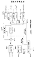
項候補群発生部136Aについて説明する。この項候補群発生部136Aは、上述の基本生成式((5)式)の各項の係数部分を除いた部分をパラメータh,vの値を用いて算出し、15個の項候補T0〜T14を発生するものである。図2は、項候補群発生部136Aの構成例を示している。
【0044】
この項候補群発生部136Aは、スタート信号ST1に基づいて、種々のタイミング信号を発生するタイミング発生器201と、このタイミング発生器201より出力されるカウントアドレスに基づいて選択信号SEL1を発生するプログラムバンク202と、パラメータh,vおよび整数定数1を入力し、プログラムバンク202より出力される選択信号SEL1に基づいて、パラメータh,vおよび整数定数1のいずれかを選択的に出力する選択器203とを有している。
【0045】
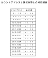
ここで、タイミング発生器201からは、図3Bに示すようにスタート信号ST1が供給された後、図3Aに示すクロック信号に同期して、図3Cに示すようにカウントアドレスが発生され、選択器203からは、図3Dに示すように、出力S1が得られる。図4は、カウントアドレスと選択器203の選択内容との対応関係を示している。
【0046】
また、項候補群発生部136Aは、選択器203の出力S1を積算するための乗算器204と、この乗算器204の乗算結果を格納するレジスタ205と、このレジスタ205に格納された乗算結果または整数定数1を入力し、これら乗算結果または整数定数1のいずれかを選択的に出力する選択器206とを有している。この選択器206の出力S2は乗算器204に供給される。この選択器206にはタイミング発生器201より、図3Eに示すように初期化タイミング信号が供給される。これにより、選択器206からは、カウントアドレスが0,4,8,・・・のように4の倍数となる毎に整数定数1が選択的に出力され、積算の初期化が行われる。なお、カウントアドレスが4の倍数でない場合は、選択器206でレジスタ205の出力S3が選択的に出力される。
【0047】
また、項候補群発生部136Aは、パラメータh,vを含まない項候補T0、すなわち1を保持するレジスタ207-0と、項候補T1〜T14を出力するレジスタ207-1〜207-14と、レジスタ205の出力S3をレジスタ207-1〜207-14に格納するか否かを制御するイネーブル器208-1〜208-14とを有している。イネーブル器208-1〜208-14のそれぞれには、タイミング発生器201より、図3Fに示すように、イネーブル信号EN1〜EN14が供給される。これにより、レジスタ207-1〜207-14は、カウントアドレスが4の倍数−1となる毎に、順次書き込みイネーブル状態となって、レジスタ205の出力S3が書き込まれる。
【0048】
図2に示す項候補群発生部136Aの動作を説明する。システムコントローラ101(図1参照)よりスタート信号ST1(図3B)が供給されると、クロック信号(図3A)に同期して、カウントアドレス(図3C)が発生される。そして、プログラムバンク202より選択器203にカウントアドレスに対応して選択信号SEL1が供給され、選択器203からはパラメータh,vまたは整数定数1が選択的に取り出される(図3D)。
【0049】
また、タイミング発生器201より選択器206に初期化タイミング信号(図3E)が供給され、選択器206ではカウントアドレスが4の倍数となる毎に、レジスタ205の出力ではなく、整数定数1が取り出される。したがって、カウントアドレスが4の倍数となる毎に、積算の初期化が行われる。
【0050】
そして、イネーブル器208-1〜208-14のそれぞれにはタイミング発生器201よりイネーブル信号EN1〜EN14(図3F)が供給され、レジスタ207-1〜207-14はカウントアドレスが4の倍数−1となる毎に順次書き込みイネーブル状態となる。したがって、レジスタ207-1〜207-14には、選択器203で選択的に取り出される4個毎の積算値が順次書き込まれていく。
【0051】
これにより、レジスタ207-1〜207-14には、(5)式に示す基本生成式の第2項〜第15項に対応した項候補T1〜T14が保持されて出力されることとなる。なお、レジスタ207-0には、上述したように、(5)式に示す基本生成式の第1項に対応した項候補T0が予め保持されており、上述の項候補T1〜T14と共に出力される。
【0052】
係数演算部136Bについて説明する。この係数演算部136Bは、クラス毎に、上述した項候補群発生部136Aより出力される項候補T0〜T14より、情報メモリバンク135より読み出される項選択情報SL0〜SL9によって項を選択し、選択された項からなる生成式により、情報メモリバンク135より読み出される係数種データAi0〜Ai9を使用して、推定式の係数データWi(i=1〜n)を演算するものである。図5は、係数演算部136Bの構成例を示している。
【0053】
この係数演算部136Bは、15個の項候補T0〜T14より、必要とする項を選択する項選択部211-0〜211-9を有している。これら項選択部211-0〜211-9では、それぞれ項選択情報SL0〜SL9に基づいて、項候補T0〜T14のいずれかを選択するか、あるいはいずれも選択しないようにされる。選択する項が10項より少ない場合には、項候補T0〜T14のいずれも選択しない項選択部が発生することとなる。
【0054】
これら項選択部211-0〜211-9には、浮動小数点形式の係数種データAi0〜Ai9の固定小数点部bi0〜bi9が供給される。上述したように項候補T0〜T14のいずれも選択しない項選択部に供給される係数種データの固定小数点部は0とされる。
【0055】
図6は、項選択部211-0の構成例を示している。この項選択部211-0は、項選択情報SL0に基づいて、項候補T0〜T14より所定の項を選択的に取り出す選択器231と、この選択器231の出力に固定小数点部bi0を乗算する乗算器232とを有している。この項選択部211-0で項候補T0〜T14のいずれも選択しない場合、選択器231からは例えば整数定数1が出力されるが、これに乗算器232で0が乗算されるため、この項選択部211-0の出力d0は0となる。なお、詳細説明は省略するが、項選択部211-1〜211-9も、項選択部211-0と同様に構成される。
【0056】
図5に戻って、また、係数演算部136Bは、項選択部211-0,211-1の出力d0,d1を加算する加算部212と、項選択部211-2,211-3の出力d2,d3を加算する加算部213と、項選択部211-4,211-5の出力d4,d5を加算する加算部214と、項選択部211-6,211-7の出力d6,d7を加算する加算部215と、項選択部211-8,211-9の出力d8,d9を加算する加算部216とを有している。
【0057】
加算部212には、係数種データAi0,Ai1の指数部ci0,ci1が供給される。加算部213には、係数種データAi2,Ai3の指数部ci2,ci3が供給される。加算部214には、係数種データAi4,Ai5の指数部ci4,ci5が供給される。加算部215には、係数種データAi6,Ai7の指数部ci6,ci7が供給される。加算部216には、係数種データAi8,Ai9の指数部ci8,ci9が供給される。
【0058】
図7は、加算部212の構成例を示している。この加算部212は、項選択部211-0の出力d0を指数部ci0に基づいてビットシフトして固定小数点方式に変換して保持するレジスタ241と、項選択部211-1の出力d1を指数部ci1に基づいてビットシフトして固定小数点方式に変換して保持するレジスタ242と、レジスタ241,242の出力を加算する加算器243と、この加算器243の加算出力を保持するレジスタ244とを有している。
【0059】
図5に戻って、また、係数演算部136Bは、加算部213,214より出力される固定小数点方式の出力を加算する加算器217と、加算部215,216より出力される固定小数点方式の出力を加算する加算器218と、これら加算器217,218の加算出力を加算する加算器219と、この加算器219の出力に加算部212の出力を加算して係数データWiを得る加算器220とを有している。
【0060】
図5に示す係数演算部136Bでは、項選択部211-0〜211-9で項候補T0〜T14より必要とする項が選択され、そして、これら項選択部211-0〜211-9で選択された項に対して、項選択部211-0〜211-9および加算部212で対応する係数種データAi0〜Ai9が乗算され、それぞれの乗算結果が加算されて、係数データWiが得られる。
【0061】
上述した係数生成回路136で生成される各クラスの係数データWi(i=1〜n)は、上述した係数メモリ134に格納される。なお、上述したように情報メモリバンク135に蓄えられている各クラスの係数種データは奇数、偶数のそれぞれのフィールドにおける2×2の単位画素ブロック内の4画素に対応した係数種データからなっていることから、係数生成回路136で生成される各クラスの係数データWiは、奇数、偶数のそれぞれのフィールドにおける2×2の単位画素ブロック内の4画素に対応した係数データからなっている。
【0062】
この係数生成回路136における各クラスの係数データWiの生成は、例えば各垂直ブランキング期間で行われる。これにより、ユーザのリモコン送信機200の操作によってパラメータh,vの値が変更されても、係数メモリ134に格納される各クラスの係数データWiを、そのパラメータh,vの値に対応したものに即座に変更でき、ユーザによる解像度の調整がスムーズに行われる。
【0063】
また、画像信号処理部110は、係数生成回路136で生成される各クラスの係数データWi(i=1〜n)に対応した正規化係数Sを、(6)式によって、演算する正規化係数演算部137と、ここで生成された正規化係数Sを、クラス毎に格納する正規化係数メモリ138とを有している。正規化係数メモリ138には上述したクラス合成回路126より出力されるクラスコードCLが読み出しアドレス情報として供給され、この正規化係数メモリ138からはクラスコードCLに対応した正規化係数Sが読み出され、後述する正規化演算回路128に供給されることとなる。
【0064】
【数5】
図8は、係数データWiと正規化係数Sの生成動作に係るタイミングを示すタイミングチャートである。
図8Aは、垂直ブランキング信号を示している。各クラスの係数データWi(i=1〜n)の生成およびその係数データWiに対応した正規化係数Sの生成は垂直ブランキング期間で行われる。図8Bに示すスタート信号ST1に対応して、項候補群発生部136Aの動作が開始され、パラメータh,vを使用して、項候補T1〜T14が生成される。
【0066】
この項候補T1〜T14の生成が終了し、項候補群発生部136Aより項候補T0〜T14が出力される状態となった後に、図8Cに示すスタート信号ST2に対応して、情報メモリバンク135より係数種データAi0〜Ai9および項選択情報SL0〜SL9の読み出しが開始される。そして、係数データWiを演算するために必要なデータおよび情報の読み出しが行われた後に、図8Dに示すスタート信号ST3に対応して、係数演算部136Bの動作が開始され、各クラスの推定式の係数データWiが順次演算され、その演算された係数データWiが係数メモリ134に書き込まれていく。
【0067】
また、係数演算部136Bで最初のクラスの係数データWiが演算された後に、図8Eに示すスタート信号ST4に対応して、正規化係数演算部137の動作が開始され、各クラスの推定式の係数データWi(i=1〜n)に対応した正規化係数Sが順次演算され、その演算された正規化係数Sが正規化係数メモリ138に書き込まれていく。
【0068】
また、画像信号処理部110は、第1のタップ選択回路121で選択的に取り出される予測タップのデータ(SD画素データ)xiと、係数メモリ134より読み出される係数データWiとから、作成すべきHD信号の画素(注目画素)のデータを演算する推定予測演算回路127を有している。
【0069】
上述したように、SD信号(525i信号)をHD信号(1050i信号)に変換する際には、SD信号の1画素に対してHD信号の4画素を得る必要があることから、この推定予測演算回路127では、HD信号を構成する2×2の単位画素ブロック毎に、画素データが生成される。すなわち、この推定予測演算回路127には、第1のタップ選択回路121より単位画素ブロック内の4画素(注目画素)に対応した予測タップのデータxiと、係数メモリ134よりその単位画素ブロックを構成する4画素に対応した係数データWiとが供給され、単位画素ブロックを構成する4画素のデータy1〜y4は、それぞれ個別に上述した(4)式の推定式で演算される。
【0070】
また、画像信号処理部110は、推定予測演算回路127より順次出力される4画素のデータy1〜y4を、正規化係数メモリ138より読み出され、それぞれの演算に使用された係数データWi(i=1〜n)に対応した正規化係数Sで除算して正規化する正規化演算回路128を有している。上述せずも、係数生成回路136で係数種データより生成式によって推定式の係数データWiを求めるものであるが、生成される係数データは丸め誤差を含み、係数データWi(i=1〜n)の総和が1.0になることは保証されない。そのため、推定予測演算回路127で演算される各画素のデータy1〜y4は、丸め誤差によってレベル変動したものとなる。上述したように、正規化演算回路128で正規化することで、その変動を除去できる。
【0071】
また、画像信号処理部110は、正規化演算回路128で正規化されて順次供給される単位画素ブロック内の4画素のデータy1′〜y4′を線順次化して1050i信号のフォーマットで出力する後処理回路129を有している。
【0072】
次に、画像信号処理部110の動作を説明する。
バッファメモリ109に記憶されているSD信号(525i信号)より、第2のタップ選択回路122で、作成すべきHD信号(1050i信号)を構成する単位画素ブロック内の4画素(注目画素)の周辺に位置する空間クラスタップのデータ(SD画素データ)が選択的に取り出される。この第2のタップ選択回路122で選択的に取り出される空間クラスタップのデータ(SD画素データ)は空間クラス検出回路124に供給される。この空間クラス検出回路124では、空間クラスタップのデータとしての各SD画素データに対してADRC処理が施されて空間クラス(主に空間内の波形表現のためのクラス分類)のクラス情報としての再量子化コードQiが得られる((1)式参照)。
【0073】
また、バッファメモリ109に記憶されているSD信号(525i信号)より、第3のタップ選択回路123で、作成すべきHD信号(1050i信号)を構成する単位画素ブロック内の4画素(注目画素)の周辺に位置する動きクラスタップのデータ(SD画素データ)が選択的に取り出される。この第3のタップ選択回路123で選択的に取り出される動きクラスタップのデータ(SD画素データ)は動きクラス検出回路125に供給される。この動きクラス検出回路125では、動きクラスタップのデータとしての各SD画素データより動きクラス(主に動きの程度を表すためのクラス分類)のクラス情報MVが得られる。
【0074】
この動き情報MVと上述した再量子化コードQiはクラス合成回路126に供給される。このクラス合成回路126では、これら動き情報MVと再量子化コードQiとから、作成すべきHD信号(1050i信号)を構成する単位画素ブロック毎にその単位画素ブロック内の4画素(注目画素)が属するクラスを示すクラスコードCLが得られる((3)式参照)。そして、このクラスコードCLは、係数メモリ134および正規化係数メモリ138に読み出しアドレス情報として供給される。
【0075】
係数メモリ134には、例えば各垂直ブランキング期間に、ユーザによって調整されたパラメータh,vの値に対応した各クラスの推定式の係数データWi(i=1〜n)が係数生成回路136で生成されて格納される。また、正規化係数メモリ138には、上述したように係数生成回路136で生成された各クラスの係数データWi(i=1〜n)に対応した正規化係数Sが正規化係数演算部137で生成されて格納される。
【0076】
係数メモリ134に上述したようにクラスコードCLが読み出しアドレス情報として供給されることで、この係数メモリ134からクラスコードCLに対応した係数データWiが読み出されて推定予測演算回路127に供給される。また、バッファメモリ109に記憶されているSD信号(525i信号)より、第1のタップ選択回路121で、作成すべきHD信号(1050i信号)を構成する単位画素ブロック内の4画素(注目画素)の周辺に位置する予測タップのデータ(SD画素データ)が選択的に取り出される。この第1のタップ選択回路121で選択的に取り出される予測タップのデータ(SD画素データ)xiは推定予測演算回路127に供給される。
【0077】
推定予測演算回路127では、予測タップのデータ(SD画素データ)xiと、係数メモリ134より読み出される4画素分の係数データWiとから、作成すべきHD信号を構成する単位画素ブロック内の4画素(注目画素)のデータy1〜y4が同時的に演算される((4)式参照)。そして、この推定予測演算回路127より順次出力されるHD信号を構成する単位画素ブロック内の4画素のデータy1〜y4は正規化演算回路128に供給される。
【0078】
正規化係数メモリ138には上述したようにクラスコードCLが読み出しアドレス情報として供給され、この正規化係数メモリ138からはクラスコードCLに対応した正規化係数S、つまり推定予測演算回路127より出力されるHD画素データy1〜y4の演算に使用された係数データWiに対応した正規化係数Sが読み出されて正規化演算回路128に供給される。この正規化演算回路128では、推定予測演算回路127より出力されるHD画素データy1〜y4がそれぞれ対応する正規化係数Sで除算されて正規化される。これにより、係数種データを用いて生成式((5)式参照)で推定式((4)式参照)の係数データを求める際の丸め誤差によるデータy1〜y4のレベル変動が除去される。
【0079】
このように正規化演算回路128で正規化されて順次出力される単位画素ブロック内の4画素のデータy1′〜y4′は後処理回路129に供給される。この後処理回路129では、正規化演算回路128より順次供給される単位画素ブロック内の4画素のデータy1′〜y4′が線順次化され、1050i信号のフォーマットで出力される。つまり、この後処理回路129からは、HD信号としての1050i信号が出力される。
【0080】
上述したように、係数生成回路136で、情報メモリバンク135よりロードされる係数種データを用いて、クラス毎に、パラメータh,vの値に対応した推定式の係数データWi(i=1〜n)が生成され、これが係数メモリ134に格納される。そして、この係数メモリ134より、クラスコードCLに対応して読み出される係数データWi(i=1〜n)を用いて推定予測演算回路127でHD画素データyが演算される。したがって、ユーザは、パラメータh,vの値を調整することで、HD信号によって得られる画像の水平および垂直の画質を、無段階になめらかに調整することができる。なおこの場合、調整されたパラメータh,vの値に対応した各クラスの係数データをその都度係数生成回路136で生成して使用するものであり、大量の係数データを格納しておくメモリを必要としない。
【0081】
また、上述したように係数生成回路136で係数種データを用いて各クラスの推定式の係数データWiを生成する際に、クラス毎に生成式の項が選択されるようになされているので、演算精度を落とすことなく、情報メモリバンク135に蓄積される係数種データや、係数データWiを得るための演算器の規模圧縮を図ることことができる。
【0082】
また、生成式の中に重みの少ない項が存在すると、それにトータルゲインの中から一定の重みが取られてしまって係数曲面の近似精度が落ちてしまうが、上述したように生成式の項の選択を可能とすることで、生成式より重みの少ない項を省略でき、従って係数曲面の近似精度を上げることができる。
【0083】
次に、情報メモリバンク135に蓄積されている係数種データおよび項選択情報の生成方法については説明する。これら係数種データおよび項選択情報は、予め学習によって生成されたものである。
【0084】
まず、係数種データの生成方法の一例について説明する。(5)式の基本生成式における係数データである係数種データwi0〜w i14を求める例を示すものとする。
ここで、以下の説明のため、(7)式のように、ti(i=0〜14)を定義する。
t0=1,t1=h,t2=h2,t3=h3,t4=h4,t5=v,
t6=hv,t7=h2v,t8=h3v,t9=v2,t10=hv2,
t11=h2v2,t12=v3,t13=hv3,t14=v4
・・・(7)
この(7)式を用いると、(5)式は、(8)式のように書き換えられる。
【0085】
【数6】
最終的に、学習によって未定係数w ij を求める。すなわち、変換方法毎かつクラス毎に、複数のSD画素データとHD画素データを用いて、二乗誤差を最小にする係数値を決定する。いわゆる最小二乗法による解法である。学習数をm、k(1≦k≦m)番目の学習データにおける残差をek、二乗誤差の総和をEとすると、(4)式および(5)式を用いて、Eは(9)式で表される。ここで、xikはSD画像のi番目の予測タップ位置におけるk番目の画素データ、ykはそれに対応するk番目のHD画像の画素データを表している。
【0087】
【数7】
最小二乗法による解法では、(9)式のw ij による偏微分が0になるようなw ij を求める。これは、(10)式で示される。
【0089】
【数8】
以下、(11)式、(12)式のように、Xipjq、Yipを定義すると、(10)式は、行列を用いて(13)式のように書き換えられる。
【0091】
【数9】
【数10】
この方程式は一般に正規方程式と呼ばれている。この正規方程式は、掃き出し法(Gauss-Jordanの消去法)等を用いて、w ij について解かれ、係数種データが算出される。
【0094】
図9は、上述した係数種データの生成方法の概念を示している。HD信号から複数のSD信号を生成する。例えば、HD信号からSD信号を生成する際に使用するフィルタの水平帯域と垂直帯域を可変するパラメータh,vをそれぞれ9段階に可変して、合計81種類のSD信号を生成している。このようにして生成した複数のSD信号とHD信号との間で学習を行って係数種データを生成する。
【0095】
図10は、上述した概念で係数種データを生成する係数種データ生成装置150の構成を示している。
この係数種データ生成装置150は、教師信号としてのHD信号(1050i信号)が入力される入力端子151と、このHD信号に対して水平および垂直の間引き処理を行って、生徒信号としてのSD信号(525i信号)を得るSD信号生成回路152とを有している。
【0096】
このSD信号生成回路152には、パラメータh,vが制御信号として供給される。このパラメータh,vに対応して、HD信号からSD信号を生成する際に使用するフィルタの水平帯域と垂直帯域とが可変される。ここで、フィルタの詳細について、いくつかの例を示す。
【0097】
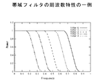
例えば、フィルタを、水平帯域を制限する帯域フィルタと垂直帯域を制限する帯域フィルタとから構成することが考えられる。この場合、図11に示すように、パラメータhまたはvの段階的な値に対応した周波数特性を設計し、逆フーリエ変換をすることにより、パラメータhまたはvの段階的な値に対応した周波数特性を持つ1次元フィルタを得ることができる。
【0098】
また例えば、フィルタを、水平帯域を制限する1次元ガウシアンフィルタと垂直帯域を制限する1次元ガウシアンフィルタとから構成することが考えられる。この1次元ガウシアンフィルタは(14)式で示される。この場合、パラメータhまたはvの段階的な値に対応して標準偏差σの値を段階的に変えることにより、パラメータhまたはvの段階的な値に対応した周波数特性を持つ1次元ガウシアンフィルタを得ることができる。
【0099】
【数11】
また例えば、フィルタを、パラメータh,vの両方で水平および垂直の周波数特性が決まる2次元フィルタF(h,v)で構成することが考えられる。この2次元フィルタの生成方法は、上述した1次元フィルタと同様に、パラメータh,vの段階的な値に対応した2次元周波数特性を設計し、2次元の逆フーリエ変換をすることにより、パラメータh,vの段階的な値に対応した2次元周波数特性を持つ2次元フィルタを得ることができる。
【0101】
また、係数種データ生成装置150は、SD信号生成回路152より出力されるSD信号(525i信号)より、HD信号(1050i信号)に係る注目画素の周辺に位置する複数のSD画素のデータを選択的に取り出して出力する第1〜第3のタップ選択回路153〜155を有している。これら第1〜第3のタップ選択回路153〜155は、上述した画像信号処理部110の第1〜第3のタップ選択回路121〜123と同様に構成される。
【0102】
また、係数種データ生成装置150は、第2のタップ選択回路154で選択的に取り出される空間クラスタップのデータ(SD画素データ)のレベル分布パターンを検出し、このレベル分布パターンに基づいて空間クラスを検出し、そのクラス情報を出力する空間クラス検出回路157を有している。この空間クラス検出回路157は、上述した画像信号処理部110の空間クラス検出回路124と同様に構成される。この空間クラス検出回路157からは、空間クラスタップのデータとしての各SD画素データ毎の再量子化コードQiが空間クラスを示すクラス情報として出力される。
【0103】
また、係数種データ生成装置150は、第3のタップ選択回路155で選択的に取り出される動きクラスタップのデータ(SD画素データ)より、主に動きの程度を表すための動きクラスを検出し、そのクラス情報MVを出力する動きクラス検出回路158を有している。この動きクラス検出回路158は、上述した画像信号処理部110の動きクラス検出回路125と同様に構成される。この動きクラス検出回路158では、第3のタップ選択回路155で選択的に取り出される動きクラスタップのデータ(SD画素データ)からフレーム間差分が算出され、さらにその差分の絶対値の平均値に対してしきい値処理が行われて動きの指標である動きクラスが検出される。
【0104】
また、係数種データ生成装置150は、空間クラス検出回路157より出力される空間クラスのクラス情報としての再量子化コードQiと、動きクラス検出回路158より出力される動きクラスのクラス情報MVに基づき、HD信号(1050i信号)に係る注目画素が属するクラスを示すクラスコードCLを得るためのクラス合成回路159を有している。このクラス合成回路159も、上述した画像信号処理部110のクラス合成回路126と同様に構成される。
【0105】
また、係数種データ生成装置150は、入力端子151に供給されるHD信号より得られる注目画素データとしての各HD画素データyと、この各HD画素データyにそれぞれ対応して第1のタップ選択回路153で選択的に取り出される予測タップのデータ(SD画素データ)xiと、各HD画素データyにそれぞれ対応してクラス合成回路159より出力されるクラスコードCLと、パラメータh,vとから、各クラス毎に、係数種データw1,0〜wn,14を得るための正規方程式((13)式参照)を生成する正規方程式生成部160を有している。
【0106】
この場合、一個のHD画素データyとそれに対応するn個の予測タップ画素データとの組み合わせで学習データが生成されるが、SD信号生成回路152へのパラメータh,vが順次変更されていって水平および垂直の帯域が段階的に変化した複数のSD信号が順次生成されていき、これにより正規方程式生成部160では多くの学習データが登録された正規方程式が生成される。
【0107】
ここで、HD信号と、そのHD信号から帯域が狭いフィルタを作用させて生成したSD信号との間で学習して算出した係数種データは、解像度の高いHD信号を得るためのものとなる。逆に、HD信号と、そのHD信号から帯域が広いフィルタを作用させて生成したSD信号との間で学習して算出した係数種データは解像度の低いHD信号を得るためのものとなる。上述したように複数のSD信号を順次生成して学習データを登録することで、連続した解像度のHD信号を得るための係数種データを求めることが可能となる。
【0108】
なお、図示せずも、第1のタップ選択回路153の前段に時間合わせ用の遅延回路を配置することで、この第1のタップ選択回路153から正規方程式生成部160に供給されるSD画素データxiのタイミング合わせを行うことができる。
【0109】
また、係数種データ生成装置150は、正規方程式生成部160でクラス毎に生成された正規方程式のデータが供給され、クラス毎に正規方程式を解いて、各クラスの係数種データw1,0〜wn,14を求める係数種データ決定部161と、この求められた係数種データw1,0〜wn,14を記憶する係数種メモリ162とを有している。係数種データ決定部161では、正規方程式が例えば掃き出し法などによって解かれて、係数データw1,0〜wn,14が求められる。
【0110】
図10に示す係数種データ生成装置150の動作を説明する。入力端子151には教師信号としてのHD信号(1050i信号)が供給され、そしてこのHD信号に対してSD信号生成回路152で水平および垂直の間引き処理が行われて生徒信号としてのSD信号(525i信号)が生成される。この場合、SD信号生成回路152にはパラメータh,vが制御信号として供給され、水平および垂直の帯域が段階的に変化した複数のSD信号が順次生成されていく。
【0111】
このSD信号(525i信号)より、第2のタップ選択回路154で、HD信号(1050i信号)に係る注目画素の周辺に位置する空間クラスタップのデータ(SD画素データ)が選択的に取り出される。この第2のタップ選択回路154で選択的に取り出される空間クラスタップのデータ(SD画素データ)は空間クラス検出回路157に供給される。この空間クラス検出回路157では、空間クラスタップのデータとしての各SD画素データに対してADRC処理が施されて空間クラス(主に空間内の波形表現のためのクラス分類)のクラス情報としての再量子化コードQiが得られる((1)式参照)。
【0112】
また、SD信号生成回路152で生成されたSD信号より、第3のタップ選択回路155で、HD信号に係る注目画素の周辺に位置する動きクラスタップのデータ(SD画素データ)が選択的に取り出される。この第3のタップ選択回路155で選択的に取り出される動きクラスタップのデータ(SD画素データ)は動きクラス検出回路158に供給される。この動きクラス検出回路158では、動きクラスタップのデータとしての各SD画素データより動きクラス(主に動きの程度を表すためのクラス分類)のクラス情報MVが得られる。
【0113】
この動き情報MVと上述した再量子化コードQiはクラス合成回路159に供給される。このクラス合成回路159では、これら動き情報MVと再量子化コードQiとから、HD信号(1050i信号)に係る注目画素が属するクラスを示すクラスコードCLが得られる((3)式参照)。
【0114】
また、SD信号生成回路152で生成されるSD信号より、第1のタップ選択回路153で、HD信号に係る注目画素の周辺に位置する予測タップのデータ(SD画素データ)が選択的に取り出される。そして、入力端子151に供給されるHD信号より得られる注目画素データとしての各HD画素データyと、この各HD画素データyにそれぞれ対応して第1のタップ選択回路153で選択的に取り出される予測タップのデータ(SD画素データ)xiと、各HD画素データyにそれぞれ対応してクラス合成回路159より出力されるクラスコードCLと、パラメータh,vとから、正規方程式生成部160では、クラス毎に、係数種データw1,0〜wn,14を生成するための正規方程式((13)式参照)が生成される。
【0115】
そして、係数種データ決定部161でその正規方程式が解かれ、各クラスの係数種データw1,0〜wn,14が求められ、その係数種データw1,0〜wn,14はクラス別にアドレス分割された係数種メモリ162に記憶される。
【0116】
なお、正規方程式生成部160で、HD画素データyとそれに対応するn個の予測タップ画素データとの組み合わせで生成される学習データを、HD画素データyが奇数、偶数のいずれのフィールドにおけるHD信号のものか、さらにはそのHD信号を構成する上述した2×2の単位画素ブロック内の4画素のいずれであるかの情報によって分別することで、奇数、偶数のそれぞれのフィールドにおけるHD信号(1050i信号)を構成する2×2の単位画素ブロック内の4画素に対応した係数種データw1,0〜wn,14を求めるための正規方程式((13)式参照)を個別に生成できる。
【0117】
これにより、係数種データ決定部では、奇数、偶数のそれぞれのフィールドにおけるHD信号(1050i信号)を構成する2×2の単位画素ブロック内の4画素に対応した係数種データw1,0〜wn,14を求めることができ、係数種メモリ162に記憶できる。
【0118】
以上は、(5)式の基本生成式における係数データである係数種データwi0〜wi、14(i=1〜n)を求める例を示したが、この基本生成式を構成する各項のうち、選択された項からなる生成式(例えば、最大で10項からなる)における係数データである係数種データも同様にして求めることができる。
【0119】
次に、項選択情報の生成方法の一例について説明する。
上述したように、基本生成式を構成する各項のうち、所定の項が選択された候補生成式を作成する。そして、この候補生成式を使用して、上述した係数種データの生成方法に基づいて、各クラスの係数種データを求める。そして、この各クラスの係数種データを用いて、各クラスの推定式の係数データWi(i=1〜n)を作成し、図1に示す画像信号処理部110におけると同様の処理で、生徒信号としてのSD信号(525i信号)よりHD信号(1050i信号)を生成する。そして、この生成されたHD信号の画素データと、上述したように生徒信号SDを作成する前のHD信号の画素データとを、クラス別に分け、対応する画素データ毎の差の総和を求めて誤差情報とする。
【0120】
上述した処理を、選択する項を順次変えた複数の候補生成式に対して繰り返して行う。その結果、クラス毎に、誤差情報が最低となる候補生成式が決定される。これにより、図1の画像信号処理部110の情報メモリバンク135に蓄積される各クラスにおける項選択情報SL0〜SL9は、基本生成式を構成する各項より誤差情報が最低となる候補生成式に対応する項を選択するものとされる。また、図1の画像信号処理部110の情報メモリバンク135に蓄積される各クラスにおける係数種データAi0〜Ai9は、誤差情報が最低となる候補生成式を使用して求められた係数種データとされる。
【0121】
なお、図1の画像信号処理部110では、情報メモリバンク135に予め蓄積されている項選択情報SL0〜SL9を用いて各クラスにおける生成式の項を選択するようにしたものであるが、例えばクラス合成回路126より得られるクラスコードCLに基づいて、その都度項選択情報を求めて用いるようにしてもよい。また、図1の画像信号処理部110では、SD信号(525i信号)に関連して得られる特徴量として、HD信号の注目画素が属するクラスを用いたものであるが、これに限定されるものではない。
【0122】
また、図1の画像信号処理部110では、係数データWi(i=1〜n)を生成する際の基本生成式として(5)式を使用したものであるが、他の次数の異なった多項式や、他の関数で表現される式でも実現可能である。
【0123】
また、図1の画像信号処理部110では、水平解像度を指定するパラメータhと垂直解像度を指定するパラメータvとを設定し、これらパラメータh,vの値を調整することで画像の水平および垂直の解像度を調整し得るものを示したが、例えばノイズ除去度(ノイズ低減度)を指定するパラメータzを設け、このパラメータzの値を調整することで画像のノイズ除去度を調整し得るものも同様に構成することができる。
【0124】
さらに、上述せずも入力画像信号Vinを種々の倍率の画像を得るための出力画像信号Voutに変換する場合、その倍率によって出力画像信号Voutを構成する画素の位相(位置)が変換する。この場合、各位相の画素を得るための推定式の係数データWiを、画素の位相情報をパラメータとする生成式により、係数種データを用いて生成することが考えられる。この場合にも、上述したようにして、各クラス毎に生成式の項の選択を行うことができ、上述した実施の形態と同様の効果を得ることができる。
【0125】
また、図1の画像信号処理部110における処理を、例えば図12に示すような画像信号処理装置300によって、ソフトウェアで実現することも可能である。
【0126】
まず、図12に示す画像信号処理装置300について説明する。この画像信号処理装置300は、装置全体の動作を制御するCPU301と、このCPU301の動作プログラムや係数種データ、項選択情報等が格納されたROM(read only memory)302と、CPU301の作業領域を構成するRAM(random access memory)303とを有している。これらCPU301、ROM302およびRAM303は、それぞれバス304に接続されている。
【0127】
また、画像信号処理装置300は、外部記憶装置としてのハードディスクドライブ(HDD)305と、フロッピーディスク306をドライブするフロッピーディスクドライブ(FDD)307とを有している。これらドライブ305,307は、それぞれバス304に接続されている。
【0128】
また、画像信号処理装置300は、インターネット等の通信網400に有線または無線で接続する通信部308を有している。この通信部308は、インタフェース309を介してバス304に接続されている。
【0129】
また、画像信号処理装置300は、ユーザインタフェース部を備えている。このユーザインタフェース部は、リモコン送信機200からのリモコン信号RMを受信するリモコン信号受信回路310と、LCD(liquid crystal display)等からなるディスプレイ311とを有している。受信回路310はインタフェース312を介してバス304に接続され、同様にディスプレイ311はインタフェース313を介してバス304に接続されている。
【0130】
また、画像信号処理装置300は、SD信号を入力するための入力端子314と、HD信号を出力するための出力端子315とを有している。入力端子314はインタフェース316を介してバス304に接続され、同様に出力端子315はインタフェース317を介してバス304に接続される。
【0131】
ここで、上述したようにROM302に処理プログラムや係数種データ、項選択情報等を予め格納しておく代わりに、例えばインターネットなどの通信網400より通信部308を介してダウンロードし、ハードディスクやRAM303に蓄積して使用することもできる。また、これら処理プログラムや係数種データ、項選択情報等をフロッピーディスク306で提供するようにしてもよい。
【0132】
また、処理すべきSD信号を入力端子314より入力する代わりに、予めハードディスクに記録しておき、あるいはインターネットなどの通信網400より通信部308を介してダウンロードしてもよい。また、処理後のHD信号を出力端子315に出力する代わり、あるいはそれと並行してディスプレイ311に供給して画像表示をしたり、さらにはハードディスクに格納したり、通信部308を介してインターネットなどの通信網400に送出するようにしてもよい。
【0133】
図13のフローチャートを参照して、図12に示す画像信号処理装置300における、SD信号よりHD信号を得るため処理手順を説明する。
【0134】
まず、ステップST1で、処理を開始し、ステップST2で、SD画素データをフレーム単位またはフィールド単位で入力する。このSD画素データが入力端子314より入力される場合には、このSD画素データをRAM303に一時的に格納する。また、このSD画素データがハードディスクに記録されている場合には、ハードディスクドライブ307でこのSD画素データを読み出し、RAM303に一時的に格納する。そして、ステップST3で、入力SD画素データの全フレームまたは全フィールドの処理が終わっているか否かを判定する。処理が終わっているときは、ステップST4で、処理を終了する。一方、処理が終わっていないときは、ステップST5に進む。
【0135】
このステップST5では、ユーザがリモコン送信機200を操作して入力した画質指定値(例えばパラメータh,vの値など)を例えばRAM303より読み込む。そして、ステップST6で、読み込んだ画質指定値および各クラスの係数種データを使用して、項選択情報で選択された項からなる生成式によって、各クラスの推定式((4)式参照)の係数データWiを生成する。
【0136】
次に、ステップST7で、ステップST2で入力されたSD画素データより、生成すべき各HD画素データに対応して、クラスタップおよび予測タップの画素データを取得する。そして、ステップST8で、入力されたSD画素データの全領域においてHD画素データを得る処理が終了したか否かを判定する。終了しているときは、ステップST2に戻り、次のフレームまたはフィールドのSD画素データの入力処理に移る。一方、処理が終了していないときは、ステップST9に進む。
【0137】
このステップST9では、ステップST7で取得されたクラスタップのSD画素データからクラスコードCLを生成する。そして、ステップST10で、そのクラスコードCLに対応した係数データと予測タップのSD画素データを使用して、推定式により、HD画素データを生成し、その後にステップST7に戻って、上述したと同様の処理を繰り返す。
【0138】
このように、図13に示すフローチャートに沿って処理をすることで、入力されたSD信号を構成するSD画素データを処理して、HD信号を構成するHD画素データを得ることができる。上述したように、このように処理して得られたHD信号は出力端子315に出力されたり、ディスプレイ311に供給されてそれによる画像が表示されたり、さらにはハードディスクドライブ305に供給されてハードディスクに記録されたりする。
【0139】
なお、上述実施の形態においては、HD信号を生成する際の推定式として線形一次方程式を使用したものを挙げたが、これに限定されるものではなく、例えば推定式として高次方程式を使用するものであってもよい。
【0140】
また、上述実施の形態においては、SD信号(525i信号)をHD信号(1050i信号)に変換する例を示したが、この発明はそれに限定されるものでなく、推定式を使用して第1の画像信号を第2の画像信号に変換するその他の場合にも同様に適用できることは勿論である。
【0141】
また、上述実地の形態においては、情報信号が画像信号である場合を示したが、この発明はこれに限定されない。例えば、情報信号が音声信号である場合にも、この発明を同様に適用することができる。
【0142】
【発明の効果】
この発明によれば、第1の情報信号を第2の情報信号に変換する際に使用される推定式の係数データを係数種データを用いて生成する際に、第1の情報信号に関連して得られる特徴量に基づいて生成式の項を選択するものであり、演算精度を落とすことなく係数種データや演算器の規模圧縮を可能にすると共に、係数曲面の近似精度を上げることが可能となる。
【図面の簡単な説明】
【図1】実施の形態としてのテレビ受信機の構成を示すブロック図である。
【図2】項候補群発生部の構成例を示すブロック図である。
【図3】項候補群発生部の動作を説明するためのタイミングチャートである。
【図4】カウントアドレスと選択内容との対応関係を示す図である。
【図5】係数演算部の構成例を示すブロック図である。
【図6】項選択部の構成例を示すブロック図である。
【図7】加算部の構成例を示すブロック図である。
【図8】係数データと正規化係数の生成動作を説明するためのタイミングチャートである。
【図9】係数種データの生成方法の一例の概念を示す図である。
【図10】係数種データ生成装置の構成例を示すブロック図である。
【図11】帯域フィルタの周波数特性の一例を示す図である。
【図12】ソフトウェアで実現するための画像信号処理装置の構成例を示すブロック図である。
【図13】画像信号の処理手順を示すフローチャートである。
【図14】525i信号と1050i信号の画素位置関係を説明するための図である。
【符号の説明】
100・・・テレビ受信機、101・・・システムコントローラ、102・・・リモコン信号受信回路、105・・・受信アンテナ、106・・・チューナ、110・・・画像信号処理部、111・・・ディスプレイ部、121・・・第1のタップ選択回路、122・・・第2のタップ選択回路、123・・・第3のタップ選択回路、124・・・空間クラス検出回路、125・・・動きクラス検出回路、126・・・クラス合成回路、127・・・推定予測演算回路、128・・・正規化演算回路、129・・・後処理回路、134・・・係数メモリ、135・・・情報メモリバンク、136・・・係数生成回路、136A・・・項候補群発生部、136B・・・係数演算部、137・・・正規化係数演算部、138・・・正規化係数メモリ、150・・・係数種データ生成装置、151・・・入力端子、152・・・SD信号生成回路、153・・・第1のタップ選択回路、154・・・第2のタップ選択回路、155・・・第3のタップ選択回路、157・・・空間クラス検出回路、158・・・動きクラス検出回路、159・・・クラス合成回路、160・・・正規方程式生成部、161・・・係数種データ決定部、162・・・係数種メモリ、200・・・リモコン送信機、300・・・画像信号処理装置、301・・・CPU、302・・・ROM、303・・・RAM、304・・・バス、305・・・ハードディスクドライブ、307・・・フロッピーディスクドライブ、308・・・通信部、309,312,313,316,317・・・インタフェース、310・・・リモコン信号受信回路、311・・・ディスプレイ、314・・・入力端子、315・・・出力端子、400・・・通信網[0001]
BACKGROUND OF THE INVENTION
The present invention is, for example, an information signal processing apparatus, an information signal processing method, an image signal processing apparatus, an image display apparatus using the same, and information that can be suitably applied when converting an NTSC video signal to a high-definition video signal. It relates to a distribution medium. More specifically, it is obtained in association with the first information signal when the coefficient data of the estimation formula used when converting the first information signal into the second information signal is generated using the coefficient seed data. An information signal processing device that enables the compression of the coefficient seed data and the scale of the computing unit without lowering the computation accuracy by selecting the term of the generation formula based on the feature quantity, and increases the approximation accuracy of the coefficient surface. Etc.
[0002]
[Prior art]
Conventionally, a format conversion for converting a 525i signal as an SD (Standard Definition) signal into a 1050i signal as an HD (High Definition) signal has been proposed. The 525i signal means an interlaced image signal having 525 lines, and the 1050i signal means an interlaced image signal having 1050 lines.
[0003]
FIG. 14 shows the pixel position relationship between the 525i signal and the 1050i signal. Here, a large dot is a pixel of a 525i signal, and a small dot is a pixel of a 1050i signal. In addition, pixel positions in odd fields are indicated by solid lines, and pixel positions in even fields are indicated by broken lines. When converting a 525i signal to a 1050i signal, it is necessary to obtain four pixels of the 1050i signal corresponding to one pixel of the 525i signal in each of the odd and even fields.
[0004]
Conventionally, when the pixel data of the 1050i signal is obtained from the pixel data of the 525i signal in order to perform the format conversion as described above, the coefficient data of the estimation formula corresponding to the phase of each pixel of the 1050i signal with respect to the pixel of the 525i signal is obtained. It has been proposed that pixel data of a 1050i signal is obtained by an estimation formula using the coefficient data stored in a memory.
[0005]
[Problems to be solved by the invention]
As described above, in the case of obtaining the pixel data of the 1050i signal by the estimation formula, the resolution of the image by the 1050i signal is fixed, and it is desired according to the image content or the like like the conventional adjustment of contrast, sharpness, etc. The resolution could not be achieved.
[0006]
Therefore, in the present invention, for example, the image quality of the image can be smoothly adjusted steplessly, the coefficient seed data and the scale of the calculator can be compressed without reducing the calculation accuracy of the coefficient data, and the approximation accuracy of the coefficient curved surface An object of the present invention is to provide an information signal processing apparatus and the like that increase the speed.
[0007]
[Means for Solving the Problems]
An information signal processing apparatus according to the present invention is an information signal processing apparatus that converts a first information signal made up of a plurality of information data into a second information signal made up of a plurality of information data. Parameter setting means for setting the value of the parameter, first memory means for storing coefficient seed data, which is coefficient data of the generation formula including the parameter for generating coefficient data of the estimation formula, and a first information signal A term selecting means for selecting a term of the generation formula based on a feature quantity obtained in relation to the above, a coefficient seed data stored in the first memory means, and a parameter value set by the parameter setting means. A coefficient data generating means for generating coefficient data of the estimation formula corresponding to the set parameter value generated by the generation formula comprising the terms selected by the term selection means; A first data selection unit that selects a plurality of first information data located around a point of interest related to a second information signal from one information signal; coefficient data generated by a coefficient data generation unit; And calculating means for obtaining information data of the attention point from the plurality of first information data selected by one data selection means using the estimation formula.
[0008]
The information signal processing method according to the present invention is an information signal processing method for converting a first information signal composed of a plurality of information data into a second information signal composed of a plurality of information data, wherein the second information signal A first step of setting a parameter value relating to the signal, a second step of selecting a generation equation term including the parameter for generating coefficient data of the estimation equation, and a coefficient type which is coefficient data of the generation equation Using the data and the parameter value set in the first step, the coefficient of the estimation formula that is generated by the generation formula including the term selected in the second step and corresponds to the set parameter value A third step of generating data, a fourth step of selecting a plurality of first information data located around the point of interest related to the second information signal from the first information signal, and a third step And a fifth step obtained by calculating the information data of the attention point using the estimation formula from the coefficient data generated in
[0009]
An information providing medium according to the present invention provides a computer program for executing each step of the information signal processing method described above.
[0010]
An image signal processing apparatus according to the present invention is an image signal processing apparatus for converting a first image signal composed of a plurality of pixel data into a second image signal composed of a plurality of pixel data, wherein the second image A parameter setting means for setting a value of a parameter relating to the signal, a memory means for storing coefficient seed data which is coefficient data of a generation formula including the parameter for generating coefficient data of an estimation formula, and a first image signal Using the term selection means for selecting the term of the generation formula based on the feature quantity obtained in association, the coefficient seed data stored in the memory means and the parameter value set by the parameter setting means, the term Coefficient data generation means for generating coefficient data of the estimation expression corresponding to the set parameter value generated by the generation expression comprising the terms selected by the selection means; Data selection means for selecting a plurality of pixel data located around the point of interest related to the second image signal from the image signal, coefficient data generated by the coefficient data generation means, and a plurality of pixels selected by the data selection means And calculating means for calculating pixel data of the attention point from the data using the estimation formula.
[0011]
The image display apparatus according to the present invention includes an image signal input means for inputting a first image signal composed of a plurality of pixel data, and a first image signal input from the image signal input means based on the plurality of pixel data. An image signal processing means for converting and outputting the second image signal, an image display means for displaying an image based on the second image signal output from the image signal processing means on the image display element, and a second image Parameter setting means for setting the value of the parameter relating to the signal. The image signal processing means is associated with the first memory means storing coefficient seed data, which is coefficient data of a generation formula including the parameters for generating coefficient data of the estimation formula, and the first image signal. Using the term selection means for selecting the term of the generation formula based on the obtained feature quantity, the coefficient seed data stored in the first memory means and the value of the parameter set by the parameter setting means, Coefficient data generation means for generating coefficient data of the estimation expression corresponding to the set parameter value generated by the generation expression comprising the term selected by the term selection means, and second from the first image signal A first data selection unit that selects a plurality of first pixel data located around the pixel of interest related to the image signal, a coefficient data generated by the coefficient data generation unit, and a first data selection unit; And a-option plurality of first pixel data, by using the estimated equation in which and a computing means capable calculates the pixel data of the pixel of interest.
[0012]
In the present invention, a parameter relating to the second information signal is set. For example, the parameter determines the quality of the output obtained by the second information signal. For example, when the information signal is an image signal, the image quality such as resolution is determined by the parameter value, and when the information signal is an audio signal, the sound quality is determined by the parameter value. For example, the parameter is phase information of the information data position of the second information signal with respect to the information data position of the first information signal. When the format or size of the second information signal is converted, this phase information changes.
[0013]
In addition, a plurality of first information data located around the point of interest related to the second information signal are selected from the first information signal. Then, in correspondence with the set parameter value, information data of the attention point is obtained. That is, coefficient seed data, which is coefficient data of a generation formula for generating coefficient data of an estimation formula, is stored in the memory means, and is set using the coefficient seed data and a set parameter value. Coefficient data of the estimation formula corresponding to the parameter value is generated, and information data of the attention point is generated from the coefficient data and the plurality of first information data using the estimation formula.
[0014]
Here, as described above, the term of the generation formula for generating the coefficient data of the estimation formula is selected based on the feature amount obtained in association with the first information signal. For example, a plurality of second information data located around a point of interest related to the second information signal from the first information signal is selected, and the point of interest detected based on the plurality of second information data The class to which the
[0015]
As described above, when the coefficient data of the estimation formula used when converting the first information signal into the second information signal is generated using the coefficient seed data, it is obtained in association with the first information signal. The term of the generation formula is selected based on the feature quantity obtained, and it is possible to reduce the scale of the coefficient seed data and the arithmetic unit without reducing the calculation accuracy, and it is possible to increase the approximation accuracy of the coefficient surface. Become.
[0016]
By calculating the sum of the coefficient data of the estimation formula generated using the coefficient seed data, and normalizing by dividing the information data of the attention point generated using the estimation formula by the total as described above. Thus, it is possible to remove the level fluctuation of the information data of the attention point due to the rounding error when obtaining the coefficient data of the estimation formula by the generation formula using the coefficient seed data.
[0017]
DETAILED DESCRIPTION OF THE INVENTION
Hereinafter, embodiments of the present invention will be described with reference to the drawings. FIG. 1 shows a configuration of a television receiver 100 as an embodiment. The television receiver 100 obtains a 525i signal as an SD signal from a broadcast signal, converts the 525i signal into a 1050i signal as an HD signal, and displays an image based on the 1050i signal.
[0018]
The television receiver 100 includes a microcomputer, and includes a system controller 101 for controlling the operation of the entire system, and a remote control
[0019]
Further, the television receiver 100 is supplied with a receiving antenna 105 and a broadcast signal (RF modulation signal) captured by the receiving antenna 105, and performs a channel selection process, an intermediate frequency amplification process, a detection process, and the like to generate an SD signal ( The
[0020]
Further, the television receiver 100 converts the SD signal (525i signal) temporarily stored in the
[0021]
The operation of the television receiver 100 shown in FIG. 1 will be described.
The SD signal (525i signal) output from the
[0022]
In addition, the user can smoothly adjust the horizontal and vertical resolutions of the image displayed on the screen of the display unit 111 steplessly as described above by operating the
[0023]
Next, details of the image signal processing unit 110 will be described. The image signal processing unit 110 selectively extracts data of a plurality of SD pixels located around the target pixel related to the HD signal (1050i signal) from the SD signal (525i signal) stored in the
[0024]
The first tap selection circuit 121 selectively extracts data of SD pixels (referred to as “prediction taps”) used for prediction. The second tap selection circuit 122 selectively extracts data of SD pixels (referred to as “space class taps”) used for class classification corresponding to the level distribution pattern of the SD pixel data. The third tap selection circuit 123 selectively extracts data of SD pixels (referred to as “motion class taps”) used for class classification corresponding to motion. When the space class is determined using SD pixel data belonging to a plurality of fields, motion information is also included in this space class.
[0025]
Further, the image signal processing unit 110 detects the level distribution pattern of the space class tap data (SD pixel data) selectively extracted by the second tap selection circuit 122, and determines the space class based on the level distribution pattern. It has a spatial class detection circuit 124 that detects and outputs the class information.
[0026]
In the space class detection circuit 124, for example, an operation is performed to compress each SD pixel data from 8-bit data to 2-bit data. The space class detection circuit 124 outputs compressed data corresponding to each SD pixel data as class information of the space class. In the present embodiment, data compression is performed by ADRC (Adaptive Dynamic Range Coding). As the information compression means, DPCM (predictive coding), VQ (vector quantization), or the like may be used in addition to ADRC.
[0027]
Originally, ADRC is an adaptive requantization method developed for high performance coding for VTR (Video Tape Recorder), but it can efficiently express local patterns of signal level with short word length. It is suitable for use in data compression. When ADRC is used, the maximum value of space class tap data (SD pixel data) is MAX, the minimum value is MIN, the dynamic range of space class tap data is DR (= MAX−MIN + 1), and the number of requantization bits Is P, the requantized code Qi as compressed data is obtained by the calculation of the equation (1) for each SD pixel data ki as the space class tap data. However, in the expression (1), [] means a truncation process. When there are Na SD pixel data as the space class tap data, i = 1 to Na.
Qi = [(ki-MIN + 0.5). 2P/ DR] (1)
[0028]
The image signal processing unit 110 detects a motion class mainly representing the degree of motion from the motion class tap data (SD pixel data) selectively extracted by the third tap selection circuit 123, and A motion class detection circuit 125 that outputs class information is provided.
[0029]
In the motion class detection circuit 125, the inter-frame difference is calculated from the motion class tap data (SD pixel data) mi, ni selectively extracted by the third tap selection circuit 123, and the average of absolute values of the differences is calculated. Threshold processing is performed on the value to detect a motion class that is an index of motion. That is, in the motion class detection circuit 125, the average value AV of the absolute value of the difference is calculated by the equation (2). When the third tap selection circuit 123 extracts, for example, six SD pixel data m1 to m6 and six SD pixel data n1 to n6 one frame before as class tap data, equation (2) Nb in is 6.
[0030]
[Expression 1]
Then, in the motion class detection circuit 125, the average value AV calculated as described above is compared with one or a plurality of threshold values to obtain class information MV of the motion class. For example, three thresholds th1, th2, th3 (th1 <th2 <th3) are prepared, and when four motion classes are detected, when AV ≦ th1, MV = 0 and th1 <AV ≦ th2 Is MV = 2 when MV = 1, th2 <AV ≦ th3, and MV = 3 when th3 <AV.
[0032]
Further, the image signal processing unit 110 is based on the re-quantization code Qi as the class information of the space class output from the space class detection circuit 124 and the class information MV of the motion class output from the motion class detection circuit 125. A class combining circuit 126 for obtaining a class code CL indicating a class to which a pixel (target pixel) of an HD signal (1050i signal) to be created belongs is provided.
[0033]
In the class synthesis circuit 126, the calculation of the class code CL is performed by the equation (3). In equation (3), Na represents the number of space class tap data (SD pixel data), and P represents the number of requantization bits in ADRC.
[0034]
[Expression 2]
The image signal processing unit 110 has a
[0036]
Further, the image signal processing unit 110 has an information memory bank 135. In the information memory bank 135, coefficient seed data for each class is stored in advance. The coefficient seed data is coefficient data of a generation formula for generating coefficient data to be stored in the
[0037]
As described above, when converting a 525i signal to a 1050i signal, it is necessary to obtain four pixels of the 1050i signal corresponding to one pixel of the 525i signal in each of the odd and even fields. The coefficient seed data in is further composed of coefficient seed data corresponding to four pixels in the 2 × 2 unit pixel block constituting the 1050i signal in each of the odd and even fields. The four pixels in the 2 × 2 unit pixel block have different phase relationships with respect to the pixels of the 525i signal.
[0038]
In the estimated prediction calculation circuit 127 described later, the HD pixel data y to be generated is calculated from the prediction tap data (SD pixel data) xi and the coefficient data Wi read from the
[0039]
[Equation 3]
In the present embodiment, equation (5) is a basic generation equation for generating coefficient data Wi (i = 1 to n) of the estimation equation for each class. The coefficient data Wi (i = 1 to n) of the estimation formula of each class is generated by a generation formula (consisting of a maximum of 10 terms) consisting of selected terms among the terms constituting this basic generation formula. . In the information memory bank 135, coefficient seed data, which is coefficient data of a generation formula composed of the terms thus selected, is stored for each class. The information memory bank 135 stores item selection information for each class. A method for generating the coefficient seed data and the term selection information will be described later.
[0041]
[Expression 4]
Further, the image signal processing unit 110 uses the coefficient seed data of each class and the values of the parameters h and v, and estimates corresponding to the values of the parameters h and v for each class according to a generation formula composed of the selected terms. A
[0043]
The term candidate
[0044]
The term candidate
[0045]
Here, after the start signal ST1 is supplied from the
[0046]
The term candidate
[0047]
The term candidate
[0048]
The operation of the term candidate
[0049]
An initialization timing signal (FIG. 3E) is supplied from the
[0050]
The enabler 208-1~ 208-14For each of the enable signals EN from the timing generator 201.1~ EN14(FIG. 3F) is supplied and the register 207-1~ 207-14Each time the count address becomes a multiple of 4
[0051]
As a result, the register 207-1~ 207-14Includes a term candidate T corresponding to the second term to the fifteenth term of the basic generation formula shown in the formula (5).1~ T14Is held and output. Note that the register 207-0As described above, the term candidate T corresponding to the first term of the basic generation formula shown in the formula (5)0Are stored in advance, and the above term candidate T1~ T14Is output together.
[0052]
The coefficient calculation unit 136B will be described. The coefficient calculation unit 136B outputs a term candidate T output from the term candidate
[0053]
The coefficient calculation unit 136B includes 15 term candidates T0~ T14Thus, a
[0054]
These
[0055]
FIG. 6 shows the term selection unit 211.-0The example of a structure is shown. This
[0056]
Returning to FIG. 5, the coefficient calculation unit 136B also includes a term selection unit 211.-0, 211-1Output d0, D1And an item selection unit 211.-2, 211-3Output d2, DThreeAn adder 213 for adding and a
[0057]
In
[0058]
FIG. 7 shows a configuration example of the adding
[0059]
Returning to FIG. 5, the coefficient calculation unit 136B also adds an adder 217 that adds the output of the fixed-point method output from the addition units 213 and 214, and the output of the fixed-point method that is output from the
[0060]
In the coefficient calculation unit 136B shown in FIG.-0~ 211-9Term candidate T0~ T14The more necessary terms are selected, and these
[0061]
The coefficient data Wi (i = 1 to n) of each class generated by the
[0062]
The generation of coefficient data Wi for each class in the
[0063]
Further, the image signal processing unit 110 calculates a normalization coefficient S corresponding to the coefficient data Wi (i = 1 to n) of each class generated by the
[0064]
[Equation 5]
FIG. 8 is a timing chart showing timings related to the generation operation of the coefficient data Wi and the normalization coefficient S.
FIG. 8A shows a vertical blanking signal. Generation of coefficient data Wi (i = 1 to n) of each class and generation of a normalization coefficient S corresponding to the coefficient data Wi are performed in the vertical blanking period. In response to the start signal ST1 shown in FIG. 8B, the operation of the term candidate
[0066]
This term candidate T1~ T14Is generated, and the term candidate T is generated by the term candidate group generation unit 136A.0~ T14Is output from the information memory bank 135 in response to the start signal ST2 shown in FIG. 8C.i0~ Ai9And term selection information SL0~ SL9Starts reading. Then, after data and information necessary for calculating the coefficient data Wi are read, the operation of the coefficient calculation unit 136B is started in response to the start signal ST3 shown in FIG. The coefficient data Wi are sequentially calculated, and the calculated coefficient data Wi is written into the
[0067]
In addition, after the coefficient data Wi of the first class is calculated by the coefficient calculation unit 136B, the operation of the normalization
[0068]
Further, the image signal processing unit 110 generates an HD to be generated from the prediction tap data (SD pixel data) xi selectively extracted by the first tap selection circuit 121 and the coefficient data Wi read from the
[0069]
As described above, when the SD signal (525i signal) is converted to the HD signal (1050i signal), it is necessary to obtain four pixels of the HD signal for one pixel of the SD signal. In the circuit 127, pixel data is generated for each 2 × 2 unit pixel block constituting the HD signal. That is, in the estimated prediction calculation circuit 127, the first tap selection circuit 121 configures the prediction pixel data xi corresponding to the four pixels (target pixel) in the unit pixel block and the unit memory block from the
[0070]
The image signal processing unit 110 also outputs 4-pixel data y sequentially output from the estimated prediction calculation circuit 127.1~ YFourIs normalized by dividing by the normalization coefficient S corresponding to the coefficient data Wi (i = 1 to n) used for each calculation. is doing. Although not described above, the
[0071]
The image signal processing unit 110 also normalizes the data y of four pixels in the unit pixel block that is normalized by the normalization calculation circuit 128 and sequentially supplied.1′ 〜YFour′ Is line-sequentially processed and output in the format of a 1050i signal.
[0072]
Next, the operation of the image signal processing unit 110 will be described.
From the SD signal (525i signal) stored in the
[0073]
In addition, from the SD signal (525i signal) stored in the
[0074]
This motion information MV and the above-described requantization code Qi are supplied to the class synthesis circuit 126. In this class synthesis circuit 126, four pixels (target pixel) in the unit pixel block are formed for each unit pixel block constituting the HD signal (1050i signal) to be created from the motion information MV and the requantization code Qi. A class code CL indicating the class to which it belongs is obtained (see equation (3)). The class code CL is supplied to the
[0075]
In the
[0076]
As described above, the class code CL is supplied to the
[0077]
In the estimated prediction calculation circuit 127, four pixels in the unit pixel block constituting the HD signal to be created from the prediction tap data (SD pixel data) xi and the coefficient data Wi for four pixels read from the
[0078]
As described above, the class code CL is supplied to the
[0079]
In this way, the data y of the four pixels in the unit pixel block which are normalized by the normalization operation circuit 128 and sequentially output.1′ 〜YFour'Is supplied to the
[0080]
As described above, the
[0081]
Further, as described above, when the
[0082]
In addition, if there is a term with a small weight in the generation formula, a certain weight is taken from the total gain and the approximation accuracy of the coefficient surface decreases. By making the selection possible, it is possible to omit terms with less weight than the generation formula, and thus it is possible to increase the approximation accuracy of the coefficient surface.
[0083]
Next, a method for generating coefficient seed data and term selection information stored in the information memory bank 135 will be described. These coefficient seed data and term selection information are generated in advance by learning.
[0084]
First, an example of a method for generating coefficient seed data will be described. (5) Coefficient seed data w which is coefficient data in the basic generation formula of the formulai0~w i14The example which calculates | requires is shown.
Here, for the following explanation, ti (i = 0 to 14) is defined as in the equation (7).
t0= 1, t1= H, t2= H2, TThree= HThree, TFour= HFour, TFive= V,
t6= Hv, t7= H2v, t8= HThreev, t9= V2, TTen= Hv2,
t11= H2v2, T12= VThree, T13= HvThree, T14= VFour
... (7)
Using this equation (7), equation (5) can be rewritten as equation (8).
[0085]
[Formula 6]
Finally, the undetermined coefficient by learningw ij Ask for. That is, for each conversion method and class, a coefficient value that minimizes the square error is determined using a plurality of SD pixel data and HD pixel data. This is a so-called least square method. The learning number is m, and the residual in the kth learning data (1 ≦ k ≦ m) is e.kWhen E is the sum of the square errors, E is expressed by equation (9) using equations (4) and (5). Where xikIs the k-th pixel data at the i-th predicted tap position of the SD image, ykRepresents pixel data of the k-th HD image corresponding thereto.
[0087]
[Expression 7]
In the least squares method, the equation (9)w ij The partial differential due to becomes zerow ij Ask for. This is shown by equation (10).
[0089]
[Equation 8]
Hereinafter, as in the equations (11) and (12), Xipjq, YipIs defined, equation (10) can be rewritten as equation (13) using a matrix.
[0091]
[Equation 9]
[Expression 10]
This equation is generally called a normal equation. This normal equation can be obtained by sweeping out (Gauss-Jordan elimination), etc.w ij The coefficient seed data is calculated.
[0094]
FIG. 9 shows the concept of the above-described coefficient seed data generation method. A plurality of SD signals are generated from the HD signal. For example, a total of 81 types of SD signals are generated by varying the parameters h and v for varying the horizontal band and vertical band of the filter used when generating the SD signal from the HD signal in 9 stages. Learning is performed between the plurality of SD signals generated in this way and the HD signal to generate coefficient seed data.
[0095]
FIG. 10 shows a configuration of a coefficient seed
The coefficient seed
[0096]
The SD signal generation circuit 152 is supplied with parameters h and v as control signals. Corresponding to the parameters h and v, the horizontal band and the vertical band of the filter used when generating the SD signal from the HD signal are varied. Here, some examples of the details of the filter are shown.
[0097]
For example, it can be considered that the filter is composed of a band filter for limiting the horizontal band and a band filter for limiting the vertical band. In this case, as shown in FIG. 11, by designing a frequency characteristic corresponding to the stepped value of the parameter h or v and performing inverse Fourier transform, the frequency characteristic corresponding to the stepped value of the parameter h or v is obtained. Can be obtained.
[0098]
For example, it is conceivable that the filter is composed of a one-dimensional Gaussian filter that limits the horizontal band and a one-dimensional Gaussian filter that limits the vertical band. This one-dimensional Gaussian filter is expressed by equation (14). In this case, a one-dimensional Gaussian filter having a frequency characteristic corresponding to the stepped value of the parameter h or v is obtained by changing the value of the standard deviation σ stepwise corresponding to the stepped value of the parameter h or v. Obtainable.
[0099]
## EQU11 ##
Further, for example, it is conceivable that the filter is constituted by a two-dimensional filter F (h, v) in which horizontal and vertical frequency characteristics are determined by both parameters h and v. This two-dimensional filter generation method, like the above-described one-dimensional filter, designs a two-dimensional frequency characteristic corresponding to the stepwise values of the parameters h and v, and performs a two-dimensional inverse Fourier transform to thereby create a parameter. A two-dimensional filter having a two-dimensional frequency characteristic corresponding to the stepwise values of h and v can be obtained.
[0101]
Further, the coefficient seed
[0102]
The coefficient seed
[0103]
The coefficient seed
[0104]
Also, the coefficient seed
[0105]
Also, the coefficient seed
[0106]
In this case, learning data is generated by a combination of one HD pixel data y and n prediction tap pixel data corresponding thereto, but the parameters h and v to the SD signal generation circuit 152 are sequentially changed. A plurality of SD signals in which the horizontal and vertical bands change stepwise are sequentially generated, whereby the normal
[0107]
Here, the coefficient seed data calculated by learning between the HD signal and the SD signal generated by applying a narrow band filter from the HD signal is used to obtain a high-resolution HD signal. Conversely, coefficient seed data calculated by learning between an HD signal and an SD signal generated by applying a filter having a wide band from the HD signal is used to obtain an HD signal having a low resolution. As described above, by sequentially generating a plurality of SD signals and registering learning data, it is possible to obtain coefficient seed data for obtaining HD signals with continuous resolution.
[0108]
Although not shown in the figure, SD pixel data supplied from the first tap selection circuit 153 to the normal
[0109]
Also, the coefficient seed
[0110]
The operation of the coefficient seed
[0111]
From this SD signal (525i signal), the second
[0112]
Further, from the SD signal generated by the SD signal generation circuit 152, the third tap selection circuit 155 selectively extracts data of the motion class tap (SD pixel data) located around the target pixel related to the HD signal. It is. The motion class tap data (SD pixel data) selectively extracted by the third tap selection circuit 155 is supplied to the motion class detection circuit 158. In this motion class detection circuit 158, class information MV of a motion class (mainly class classification for representing the degree of motion) is obtained from each SD pixel data as motion class tap data.
[0113]
The motion information MV and the above-described requantization code Qi are supplied to the
[0114]
Further, from the SD signal generated by the SD signal generation circuit 152, the first tap selection circuit 153 selectively extracts data of prediction taps (SD pixel data) located around the target pixel related to the HD signal. . Then, each HD pixel data y as target pixel data obtained from the HD signal supplied to the
[0115]
Then, the coefficient seed data determining unit 161 solves the normal equation, and the coefficient seed data w of each class.1,0~ Wn, 14Is obtained and its coefficient seed data w1,0~ Wn, 14Is stored in the
[0116]
The normal
[0117]
As a result, the coefficient seed data determination unit determines coefficient seed data w corresponding to four pixels in the 2 × 2 unit pixel block constituting the HD signal (1050i signal) in each of the odd and even fields.1,0~ Wn, 14Can be obtained and stored in the
[0118]
The above is the coefficient seed data w which is the coefficient data in the basic generation formula of the formula (5).i0~ Wi, 14Although an example in which (i = 1 to n) is obtained is shown, coefficient data in a generation formula (for example, consisting of 10 terms at the maximum) consisting of selected terms among the terms constituting this basic generation formula. The coefficient seed data can be obtained in the same manner.
[0119]
Next, an example of a method for generating item selection information will be described.
As described above, a candidate generation formula is created in which a predetermined term is selected from the terms constituting the basic generation formula. Then, using this candidate generation formula, the coefficient seed data of each class is obtained based on the above-described coefficient seed data generation method. Then, coefficient data Wi (i = 1 to n) of the estimation formula of each class is created using the coefficient seed data of each class, and the student performs the same processing as in the image signal processing unit 110 shown in FIG. An HD signal (1050i signal) is generated from the SD signal (525i signal) as a signal. Then, the generated pixel data of the HD signal and the pixel data of the HD signal before creating the student signal SD as described above are classified by class, and the sum of differences for each corresponding pixel data is obtained to obtain an error. Information.
[0120]
The above-described processing is repeated for a plurality of candidate generation formulas in which the terms to be selected are sequentially changed. As a result, for each class, a candidate generation formula that minimizes error information is determined. Thereby, the term selection information SL in each class stored in the information memory bank 135 of the image signal processing unit 110 in FIG.0~ SL9Is used to select a term corresponding to a candidate generation formula having the lowest error information from each of the terms constituting the basic generation formula. The coefficient seed data A in each class stored in the information memory bank 135 of the image signal processing unit 110 in FIG.i0~ Ai9Is the coefficient seed data obtained using the candidate generation formula that minimizes the error information.
[0121]
In the image signal processing unit 110 in FIG. 1, the item selection information SL stored in the information memory bank 135 in advance.0~ SL9Is used to select the term of the generation formula in each class. For example, each term is selected based on the class code CL obtained from the class synthesis circuit 126.ChoiceInformation may be obtained and used. In the image signal processing unit 110 in FIG. 1, the class to which the target pixel of the HD signal belongs is used as the feature quantity obtained in relation to the SD signal (525i signal). is not.
[0122]
The image signal processing unit 110 in FIG. 1 uses the expression (5) as a basic generation expression when generating the coefficient data Wi (i = 1 to n), but other polynomials having different orders. It can also be realized by expressions expressed by other functions.
[0123]
In addition, the image signal processing unit 110 in FIG. 1 sets a parameter h for specifying the horizontal resolution and a parameter v for specifying the vertical resolution, and adjusts the values of these parameters h and v to adjust the horizontal and vertical directions of the image. Although what can adjust the resolution is shown, for example, a parameter z that specifies the noise removal degree (noise reduction degree) is provided, and the value that can adjust the value of the parameter z is the same as that that can adjust the noise removal degree of the image. Can be configured.
[0124]
Further, when the input image signal Vin is converted into the output image signal Vout for obtaining images with various magnifications, the phase (position) of the pixels constituting the output image signal Vout is converted according to the magnification. In this case, it is conceivable that the coefficient data Wi of the estimation formula for obtaining the pixel of each phase is generated using the coefficient seed data by a generation formula using the phase information of the pixel as a parameter. Also in this case, as described above, the term of the generation formula can be selected for each class, and the same effect as the above-described embodiment can be obtained.
[0125]
Further, the processing in the image signal processing unit 110 in FIG. 1 can be realized by software by an image
[0126]
First, the image
[0127]
The image
[0128]
In addition, the image
[0129]
In addition, the image
[0130]
The image
[0131]
Here, instead of storing the processing program, coefficient seed data, term selection information, and the like in advance in the ROM 302 as described above, for example, they are downloaded from the
[0132]
Further, instead of inputting the SD signal to be processed from the input terminal 314, it may be recorded in advance on a hard disk or downloaded from the
[0133]
A processing procedure for obtaining an HD signal from an SD signal in the image
[0134]
First, in step ST1, processing is started, and in step ST2, SD pixel data is input in frame units or field units. When the SD pixel data is input from the input terminal 314, the SD pixel data is temporarily stored in the RAM 303. When this SD pixel data is recorded on the hard disk, this SD pixel data is read by the
[0135]
In step ST5, an image quality designation value (for example, values of parameters h and v) input by the user operating the
[0136]
Next, in step ST7, the pixel data of the class tap and the prediction tap is acquired from the SD pixel data input in step ST2 corresponding to each HD pixel data to be generated. In step ST8, it is determined whether or not the processing for obtaining HD pixel data has been completed in all areas of the input SD pixel data. If completed, the process returns to step ST2 and proceeds to the input process of SD pixel data of the next frame or field. On the other hand, when the process is not completed, the process proceeds to step ST9.
[0137]
In this step ST9, the class code CL is generated from the SD pixel data of the class tap acquired in step ST7. In step ST10, using the coefficient data corresponding to the class code CL and the SD pixel data of the prediction tap, HD pixel data is generated by the estimation formula, and then the process returns to step ST7 and is the same as described above. Repeat the process.
[0138]
In this way, by performing processing according to the flowchart shown in FIG. 13, it is possible to process the SD pixel data constituting the input SD signal and obtain HD pixel data constituting the HD signal. As described above, the HD signal obtained by such processing is output to the output terminal 315, supplied to the display 311 to display an image, and further supplied to the hard disk drive 305 to be stored on the hard disk. It is recorded.
[0139]
In the above-described embodiment, the linear equation is used as the estimation equation when generating the HD signal. However, the present invention is not limited to this, and for example, a higher-order equation is used as the estimation equation. It may be a thing.
[0140]
In the above-described embodiment, an example in which an SD signal (525i signal) is converted into an HD signal (1050i signal) has been described. However, the present invention is not limited to this, and the first equation is estimated using an estimation formula. Of course, the present invention can be similarly applied to other cases in which the image signal is converted into the second image signal.
[0141]
Moreover, although the case where the information signal is an image signal has been shown in the above-described embodiment, the present invention is not limited to this. For example, the present invention can be similarly applied when the information signal is an audio signal.
[0142]
【The invention's effect】
According to this invention, when the coefficient data of the estimation formula used when converting the first information signal into the second information signal is generated using the coefficient seed data, the first information signal is related to the first information signal. The term of the generation formula is selected based on the feature value obtained in this way, and it is possible to reduce the scale of the coefficient seed data and the arithmetic unit without reducing the calculation accuracy, and to increase the approximation accuracy of the coefficient surface. It becomes.
[Brief description of the drawings]
FIG. 1 is a block diagram illustrating a configuration of a television receiver as an embodiment.
FIG. 2 is a block diagram illustrating a configuration example of a term candidate group generation unit.
FIG. 3 is a timing chart for explaining an operation of a term candidate group generation unit;
FIG. 4 is a diagram illustrating a correspondence relationship between count addresses and selection contents.
FIG. 5 is a block diagram illustrating a configuration example of a coefficient calculation unit.
FIG. 6 is a block diagram illustrating a configuration example of a term selection unit.
FIG. 7 is a block diagram illustrating a configuration example of an adding unit.
FIG. 8 is a timing chart for explaining the generation operation of coefficient data and a normalization coefficient.
FIG. 9 is a diagram illustrating a concept of an example of a generation method of coefficient seed data.
FIG. 10 is a block diagram illustrating a configuration example of a coefficient seed data generation apparatus.
FIG. 11 is a diagram illustrating an example of frequency characteristics of a band-pass filter.
FIG. 12 is a block diagram illustrating a configuration example of an image signal processing device to be realized by software.
FIG. 13 is a flowchart showing a processing procedure of an image signal.
FIG. 14 is a diagram for explaining a pixel positional relationship between a 525i signal and a 1050i signal.
[Explanation of symbols]
DESCRIPTION OF SYMBOLS 100 ... Television receiver, 101 ... System controller, 102 ... Remote control signal receiving circuit, 105 ... Receiving antenna, 106 ... Tuner, 110 ... Image signal processing part, 111 ... Display unit 121... First tap selection circuit 122... Second tap selection circuit 123. Third tap selection circuit 124... Spatial class detection circuit 125. Class detection circuit, 126... Class synthesis circuit, 127... Estimation prediction calculation circuit, 128... Normalization calculation circuit, 129 .. post-processing circuit, 134.
Claims (23)
上記第2の情報信号に係るパラメータの値を設定するパラメータ設定手段と、
推定式の係数データを生成する上記パラメータを含む生成式の係数データである係数種データが記憶された第1のメモリ手段と、
上記第1の情報信号に関連して得られる特徴量に基づいて上記生成式の項を選択する項選択手段と、
上記第1のメモリ手段に記憶されている係数種データと、上記パラメータ設定手段で設定された上記パラメータの値とを用いて、上記項選択手段で選択された項からなる上記生成式によって生成され、上記設定されたパラメータの値に対応した上記推定式の係数データを発生する係数データ発生手段と、
上記第1の情報信号から、上記第2の情報信号に係る注目点の周辺に位置する複数の第1の情報データを選択する第1のデータ選択手段と、
上記係数データ発生手段で発生された上記係数データと上記第1のデータ選択手段で選択された上記複数の第1の情報データとから、上記推定式を用いて上記注目点の情報データを算出して得る演算手段と
を備えることを特徴とする情報信号処理装置。An information signal processing device for converting a first information signal composed of a plurality of information data into a second information signal composed of a plurality of information data,
Parameter setting means for setting a parameter value relating to the second information signal;
First memory means for storing coefficient seed data, which is coefficient data of a generation formula including the parameters for generating coefficient data of an estimation formula;
A term selection means for selecting a term of the generation formula based on a feature amount obtained in relation to the first information signal;
Using the coefficient seed data stored in the first memory means and the value of the parameter set by the parameter setting means, it is generated by the generation formula consisting of the terms selected by the term selection means. Coefficient data generating means for generating coefficient data of the estimation formula corresponding to the set parameter value;
First data selection means for selecting, from the first information signal, a plurality of first information data located around a point of interest related to the second information signal;
From the coefficient data generated by the coefficient data generation means and the plurality of first information data selected by the first data selection means, the information data of the attention point is calculated using the estimation formula. An information signal processing apparatus comprising: an arithmetic means that is obtained.
上記第2のデータ選択手段で選択された上記複数の第2の情報データに基づいて、上記注目点が属するクラスを検出するクラス検出手段とをさらに備え、
上記第1のメモリ手段には、上記クラス検出手段で検出されるクラス毎に予め求められた上記係数種データが記憶されており、
上記係数データ発生手段は、上記クラス検出手段で検出されたクラスおよび上記パラメータ設定手段で設定された上記パラメータの値に対応した上記推定式の係数データを発生することを特徴とする請求項1に記載の情報信号処理装置。Second data selection means for selecting, from the first information signal, a plurality of second information data located around the point of interest related to the second information signal;
Class detection means for detecting a class to which the attention point belongs based on the plurality of second information data selected by the second data selection means;
The first memory means stores the coefficient seed data obtained in advance for each class detected by the class detection means,
The coefficient data generation means generates coefficient data of the estimation formula corresponding to the class detected by the class detection means and the parameter value set by the parameter setting means. The information signal processing apparatus described.
上記第1のメモリ手段に記憶されている係数種データと上記パラメータ設定手段で設定された上記パラメータの値とを用い、上記項選択手段で選択された項からなる上記生成式により、上記クラス検出手段で検出されるクラス毎に上記推定式の係数データを生成する係数データ生成手段と、
上記係数データ生成手段で生成された各クラスにおける上記推定式の係数データを記憶する第2のメモリ手段と、
上記第2のメモリ手段より上記クラス検出手段で検出されたクラスに対応した上記推定式の係数データを読み出して出力する係数データ読み出し手段と
を有してなることを特徴とする請求項2に記載の情報信号処理装置。The coefficient data generating means is
The class detection is performed by the generation formula including the term selected by the term selection unit using the coefficient seed data stored in the first memory unit and the value of the parameter set by the parameter setting unit. Coefficient data generation means for generating coefficient data of the estimation formula for each class detected by the means;
Second memory means for storing coefficient data of the estimation formula in each class generated by the coefficient data generating means;
3. Coefficient data reading means for reading out and outputting coefficient data of the estimation formula corresponding to the class detected by the class detecting means from the second memory means. Information signal processing device.
上記演算手段で得られた上記注目点の情報データを上記加算手段で求められた上記総和で除算して正規化する正規化手段をさらに備える
ことを特徴とする請求項1に記載の情報信号処理装置。Adding means for obtaining a sum of coefficient data of the estimation formula generated by the coefficient data generating means;
The information signal processing according to claim 1, further comprising: a normalizing unit that normalizes the information data of the attention point obtained by the computing unit by dividing the information data by the sum obtained by the adding unit. apparatus.
ことを特徴とする請求項2に記載の情報信号処理装置。The information signal processing apparatus according to claim 2, wherein the feature quantity obtained in association with the first information signal is a class detected by the class detection unit.
上記特徴量より項選択情報を取得する情報取得手段を有し、
上記情報取得手段で取得された項選択情報を使用して上記生成式の項を選択する
ことを特徴とする請求項1に記載の情報信号処理装置。The above item selection means is:
Having information acquisition means for acquiring the item selection information from the feature amount;
The information signal processing apparatus according to claim 1, wherein the term of the generation formula is selected using the term selection information acquired by the information acquisition unit.
ことを特徴とする請求項6に記載の情報信号処理装置。The information signal processing apparatus according to claim 6, wherein the information acquisition unit includes a ROM table.
上記第2の画像信号に係るパラメータの値を設定するパラメータ設定手段と、
推定式の係数データを生成する上記パラメータを含む生成式の係数データである係数種データが記憶されたメモリ手段と、
上記第1の画像信号に関連して得られる特徴量に基づいて上記生成式の項を選択する項選択手段と、
上記メモリ手段に記憶されている係数種データと、上記パラメータ設定手段で設定された上記パラメータの値とを用いて、上記項選択手段で選択された項からなる上記生成式によって生成され、上記設定されたパラメータの値に対応した上記推定式の係数データを発生する係数データ発生手段と、
上記第1の画像信号から、上記第2の画像信号に係る注目点の周辺に位置する複数の画素データを選択するデータ選択手段と、
上記係数データ発生手段で発生された上記係数データと上記データ選択手段で選択された上記複数の画素データとから、上記推定式を用いて上記注目点の画素データを算出して得る演算手段と
を備えることを特徴とする画像信号処理装置。An image signal processing apparatus that converts a first image signal composed of a plurality of pixel data into a second image signal composed of a plurality of pixel data,
Parameter setting means for setting a parameter value relating to the second image signal;
Memory means for storing coefficient seed data which is coefficient data of a generation formula including the above parameters for generating coefficient data of an estimation formula;
A term selection means for selecting a term of the generation formula based on a feature amount obtained in relation to the first image signal;
Using the coefficient seed data stored in the memory means and the value of the parameter set by the parameter setting means, it is generated by the generation formula consisting of the term selected by the term selecting means, and the setting is made Coefficient data generating means for generating coefficient data of the estimation formula corresponding to the parameter value,
Data selection means for selecting, from the first image signal, a plurality of pixel data located around a point of interest related to the second image signal;
An arithmetic means for calculating the pixel data of the attention point from the coefficient data generated by the coefficient data generating means and the plurality of pixel data selected by the data selecting means using the estimation formula; An image signal processing apparatus comprising:
上記画像信号入力手段より入力された上記第1の画像信号を複数の画素データからなる第2の画像信号に変換して出力する画像信号処理手段と、
上記画像信号処理手段より出力される上記第2の画像信号による画像を画像表示素子に表示する画像表示手段と、
上記第2の画像信号に係るパラメータの値を設定するパラメータ設定手段とを有してなり、
上記画像信号処理手段は、
推定式の係数データを生成する上記パラメータを含む生成式の係数データである係数種データが記憶された第1のメモリ手段と、
上記第1の画像信号に関連して得られる特徴量に基づいて上記生成式の項を選択する項選択手段と、
上記第1のメモリ手段に記憶されている係数種データと、上記パラメータ設定手段で設定された上記パラメータの値とを用いて、上記項選択手段で選択された項からなる上記生成式によって生成され、上記設定されたパラメータの値に対応した上記推定式の係数データを発生する係数データ発生手段と、
上記第1の画像信号から、上記第2の画像信号に係る注目画素の周辺に位置する複数の第1の画素データを選択する第1のデータ選択手段と、
上記係数データ発生手段で発生された上記係数データと上記第1のデータ選択手段で選択された上記複数の第1の画素データとから、上記推定式を用いて上記注目画素の画素データを算出して得る演算手段とを備える
ことを特徴とする画像表示装置。Image signal input means for inputting a first image signal composed of a plurality of pixel data;
Image signal processing means for converting the first image signal input from the image signal input means into a second image signal comprising a plurality of pixel data and outputting the second image signal;
Image display means for displaying an image based on the second image signal output from the image signal processing means on an image display element;
Parameter setting means for setting a parameter value relating to the second image signal,
The image signal processing means includes:
First memory means for storing coefficient seed data, which is coefficient data of a generation formula including the parameters for generating coefficient data of an estimation formula;
A term selection means for selecting a term of the generation formula based on a feature amount obtained in relation to the first image signal;
Using the coefficient seed data stored in the first memory means and the value of the parameter set by the parameter setting means, it is generated by the generation formula consisting of the terms selected by the term selection means. Coefficient data generating means for generating coefficient data of the estimation formula corresponding to the set parameter value;
First data selection means for selecting, from the first image signal, a plurality of first pixel data located around a pixel of interest related to the second image signal;
From the coefficient data generated by the coefficient data generation means and the plurality of first pixel data selected by the first data selection means, the pixel data of the target pixel is calculated using the estimation formula. An image display device comprising: an arithmetic operation unit obtained.
上記第2のデータ選択手段で選択された上記第2の画素データに基づいて、上記注目画素が属するクラスを検出するクラス検出手段とをさらに備え、
上記第1のメモリ手段には、上記クラス検出手段で検出されるクラス毎に予め求められた上記係数種データが記憶されており、
上記係数データ発生手段は、上記クラス検出手段で検出されたクラスおよび上記パラメータ設定手段で設定された上記パラメータの値に対応した上記推定式の係数データを発生する
ことを特徴とする請求項9に記載の画像表示装置。Second data selection means for selecting, from the first image signal, a plurality of second pixel data located around the pixel of interest related to the second image signal;
Class detecting means for detecting a class to which the pixel of interest belongs based on the second pixel data selected by the second data selecting means;
The first memory means stores the coefficient seed data obtained in advance for each class detected by the class detection means,
The coefficient data generation means generates coefficient data of the estimation formula corresponding to the class detected by the class detection means and the parameter value set by the parameter setting means. The image display device described.
上記第1のメモリ手段に記憶されている係数種データと上記パラメータ設定手段で設定された上記パラメータの値とを用い、上記項選択手段で選択された項からなる上記生成式により、上記クラス検出手段で検出されるクラス毎に上記推定式の係数データを生成する係数データ生成手段と、
上記係数データ生成手段で生成された各クラスにおける上記推定式の係数データを記憶する第2のメモリ手段と、
上記第2のメモリ手段より上記クラス検出手段で検出されたクラスに対応した上記推定式の係数データを読み出して出力する係数データ読み出し手段と
を有してなることを特徴とする請求項10に記載の画像表示装置。The coefficient data generating means is
The class detection is performed by the generation formula including the term selected by the term selection unit using the coefficient seed data stored in the first memory unit and the value of the parameter set by the parameter setting unit. Coefficient data generation means for generating coefficient data of the estimation formula for each class detected by the means;
Second memory means for storing coefficient data of the estimation formula in each class generated by the coefficient data generating means;
11. Coefficient data reading means for reading out and outputting coefficient data of the estimation formula corresponding to the class detected by the class detecting means from the second memory means. Image display device.
上記演算手段で得られた上記注目画素の画素データを上記加算手段で求められた上記総和で除算して正規化する正規化手段をさらに備える
ことを特徴とする請求項9に記載の画像表示装置。Adding means for obtaining a sum of coefficient data of the estimation formula generated by the coefficient data generating means;
The image display device according to claim 9, further comprising normalizing means for normalizing the pixel data of the pixel of interest obtained by the computing means by dividing the pixel data by the sum obtained by the adding means. .
ことを特徴とする請求項10に記載の画像表示装置。The image display device according to claim 10, wherein the feature amount obtained in association with the first image signal is a class detected by the class detection unit.
上記特徴量より項選択情報を取得する情報取得手段を有し、
上記情報取得手段で取得された項選択情報を使用して上記生成式の項を選択する
ことを特徴とする請求項9に記載の画像表示装置。The above item selection means is:
Having information acquisition means for acquiring the item selection information from the feature amount;
The image display device according to claim 9, wherein the term of the generation formula is selected using the term selection information acquired by the information acquisition unit.
ことを特徴とする請求項14に記載の画像表示装置。The image display apparatus according to claim 14, wherein the information acquisition unit includes a ROM table.
上記第2の情報信号に係るパラメータの値を設定する第1のステップと、
推定式の係数データを生成する上記パラメータを含む生成式の項を選択する第2のステップと、
上記生成式の係数データである係数種データと、上記第1のステップで設定された上記パラメータの値とを用いて、上記第2のステップで選択された項からなる上記生成式によって生成され、上記設定されたパラメータの値に対応した上記推定式の係数データを発生する第3のステップと、
上記第1の情報信号から、上記第2の情報信号に係る注目点の周辺に位置する複数の第1の情報データを選択する第4のステップと、
上記第3のステップで発生された上記係数データと上記第4のステップで選択された上記複数の第1の情報データとから、上記推定式を用いて上記注目点の情報データを算出して得る第5のステップと
を備えることを特徴とする情報信号処理方法。An information signal processing method for converting a first information signal composed of a plurality of information data into a second information signal composed of a plurality of information data,
A first step of setting a parameter value related to the second information signal;
A second step of selecting a term of the generation formula including the parameter for generating coefficient data of the estimation formula;
Using the coefficient seed data, which is the coefficient data of the generation formula, and the value of the parameter set in the first step, generated by the generation formula consisting of the terms selected in the second step, A third step of generating coefficient data of the estimation equation corresponding to the set parameter value;
A fourth step of selecting, from the first information signal, a plurality of first information data located around a point of interest related to the second information signal;
Obtained from the coefficient data generated in the third step and the plurality of first information data selected in the fourth step by calculating the information data of the attention point using the estimation formula An information signal processing method comprising: a fifth step.
上記第6のステップで選択された上記複数の第2の情報データに基づいて、上記注目点が属するクラスを検出する第7のステップとをさらに備え、
上記第3のステップでは、上記第7のステップで検出されたクラスおよび上記第1のステップで設定された上記パラメータの値に対応した上記推定式の係数データを発生する
ことを特徴とする請求項16に記載の情報信号処理方法。A sixth step of selecting, from the first information signal, a plurality of second information data located around a point of interest related to the second information signal;
A seventh step of detecting a class to which the attention point belongs based on the plurality of second information data selected in the sixth step;
The coefficient data of the estimation formula corresponding to the class detected in the seventh step and the value of the parameter set in the first step is generated in the third step. 16. The information signal processing method according to 16.
上記第7のステップで検出されるクラス毎の上記係数種データと上記第1のステップで設定された上記パラメータの値とを用い、上記第2のステップで選択された項からなる上記生成式により、上記クラス毎に上記推定式の係数データを生成するステップと、
上記生成された各クラスにおける上記推定式の係数データをメモリ手段に記憶するステップと、
上記メモリ手段より上記第7のステップで検出されたクラスに対応した上記推定式の係数データを読み出して出力するステップとを有する
ことを特徴とする請求項17に記載の情報信号処理方法。The third step is
Using the coefficient seed data for each class detected in the seventh step and the value of the parameter set in the first step, and using the generation formula comprising the term selected in the second step Generating coefficient data of the estimation formula for each class;
Storing coefficient data of the estimation formula in each of the generated classes in a memory means;
18. The information signal processing method according to claim 17, further comprising: reading out and outputting coefficient data of the estimation formula corresponding to the class detected in the seventh step from the memory means.
上記第5のステップで得られた上記注目点の情報データを上記第8のステップで求められる上記総和で除算して正規化する第9のステップとをさらに備える
ことを特徴とする請求項16に記載の情報信号処理方法。An eighth step of obtaining a sum of coefficient data of the estimation formula generated in the third step;
The information processing method according to claim 16, further comprising: a ninth step of normalizing by dividing the information data of the attention point obtained in the fifth step by the sum obtained in the eighth step. The information signal processing method described.
ことを特徴とする請求項17に記載の情報信号処理方法。The information signal processing method according to claim 17, wherein the feature amount obtained in association with the first information signal is a class detected in the seventh step.
上記特徴量より項選択情報を取得し、該項選択情報を使用して上記生成式の項を選択する
ことを特徴とする請求項16に記載の情報信号処理方法。In the second step,
The information signal processing method according to claim 16, wherein term selection information is acquired from the feature amount, and the term of the generation formula is selected using the term selection information.
ことを特徴とする請求項21に記載の情報信号処理方法。The information signal processing method according to claim 21, wherein in the second step, the light selection information is acquired from the feature amount using a ROM table.
上記第2の情報信号に係るパラメータの値を設定する第1のステップと、
推定式の係数データを生成する上記パラメータを含む生成式の項を選択する第2のステップと、
上記生成式の係数データである係数種データと、上記第1のステップで設定された上記パラメータの値とを用いて、上記第2のステップで選択された項からなる上記生成式によって生成され、上記設定されたパラメータの値に対応した上記推定式の係数データを発生する第3のステップと、
上記第1の情報信号から、上記第2の情報信号に係る注目点の周辺に位置する複数の第1の情報データを選択する第4のステップと、
上記第3のステップで発生された上記係数データと上記第4のステップで選択された上記複数の第1の情報データとから、上記推定式を用いて上記注目点の情報データを算出して得る第5のステップと
をコンピュータに実行させるためのコンピュータプログラムを記録したコンピュータ読み取り可能な情報提供媒体。In order to convert a first information signal composed of a plurality of information data into a second information signal composed of a plurality of information data,
A first step of setting a parameter value related to the second information signal;
A second step of selecting a term of the generation formula including the parameter for generating coefficient data of the estimation formula;
Using the coefficient seed data, which is the coefficient data of the generation formula, and the value of the parameter set in the first step, generated by the generation formula consisting of the terms selected in the second step, A third step of generating coefficient data of the estimation equation corresponding to the set parameter value;
A fourth step of selecting, from the first information signal, a plurality of first information data located around a point of interest related to the second information signal;
Obtained from the coefficient data generated in the third step and the plurality of first information data selected in the fourth step by calculating the information data of the attention point using the estimation formula A computer-readable information providing medium recording a computer program for causing a computer to execute the fifth step.
Priority Applications (7)
| Application Number | Priority Date | Filing Date | Title |
|---|---|---|---|
| JP2000395872A JP4517264B2 (en) | 2000-12-26 | 2000-12-26 | Information signal processing apparatus, information signal processing method, image signal processing apparatus, image display apparatus using the same, and information providing medium |
| KR1020027011103A KR100770067B1 (en) | 2000-12-26 | 2001-12-26 | Information signal processing device, information signal processing method, image signal processing device, image display comprising the same, and information providing medium |
| CNB018055389A CN1220376C (en) | 2000-12-26 | 2001-12-26 | Information signal processing device, information singal processing method, image signal processing device and image display using the image signal processing device |
| DE60142360T DE60142360D1 (en) | 2000-12-26 | 2001-12-26 | INFORMATION SIGNAL PROCESSING DEVICE, INFORMATION SIGNAL PROCESSING METHOD, IMAGE SIGNAL PROCESSING APPARATUS, IMAGE DISPLAY WITH IT AND INFORMATION PROCESSING |
| PCT/JP2001/011452 WO2002052538A1 (en) | 2000-12-26 | 2001-12-26 | Information signal processing device, information signal processing method, image signal processing device, image display comprising the same, and information providing medium |
| US10/204,687 US7061539B2 (en) | 2000-12-26 | 2001-12-26 | Information signal processing device, information signal processing method, image signal processing device, image display comprising the same, and information providing medium |
| EP01272328A EP1353320B1 (en) | 2000-12-26 | 2001-12-26 | Information signal processing device, information signal processing method, image signal processing device, image display comprising the same, and information providing medium |
Applications Claiming Priority (1)
| Application Number | Priority Date | Filing Date | Title |
|---|---|---|---|
| JP2000395872A JP4517264B2 (en) | 2000-12-26 | 2000-12-26 | Information signal processing apparatus, information signal processing method, image signal processing apparatus, image display apparatus using the same, and information providing medium |
Publications (3)
| Publication Number | Publication Date |
|---|---|
| JP2002199353A JP2002199353A (en) | 2002-07-12 |
| JP2002199353A5 JP2002199353A5 (en) | 2007-03-22 |
| JP4517264B2 true JP4517264B2 (en) | 2010-08-04 |
Family
ID=18861260
Family Applications (1)
| Application Number | Title | Priority Date | Filing Date |
|---|---|---|---|
| JP2000395872A Expired - Fee Related JP4517264B2 (en) | 2000-12-26 | 2000-12-26 | Information signal processing apparatus, information signal processing method, image signal processing apparatus, image display apparatus using the same, and information providing medium |
Country Status (7)
| Country | Link |
|---|---|
| US (1) | US7061539B2 (en) |
| EP (1) | EP1353320B1 (en) |
| JP (1) | JP4517264B2 (en) |
| KR (1) | KR100770067B1 (en) |
| CN (1) | CN1220376C (en) |
| DE (1) | DE60142360D1 (en) |
| WO (1) | WO2002052538A1 (en) |
Families Citing this family (11)
| Publication number | Priority date | Publication date | Assignee | Title |
|---|---|---|---|---|
| WO2003065712A1 (en) * | 2002-01-30 | 2003-08-07 | Sony Corporation | Apparatus, method and program for generating coefficient type data or coefficient data used in image display apparatus, computer-readable medium containing the program |
| JP4055655B2 (en) * | 2003-05-29 | 2008-03-05 | ソニー株式会社 | Coefficient generation apparatus and generation method, class configuration generation apparatus and generation method, information signal processing apparatus, and program for executing each method |
| JP4265291B2 (en) * | 2003-06-06 | 2009-05-20 | ソニー株式会社 | Information signal processing apparatus and method, and program for executing information signal processing method |
| JP4311166B2 (en) * | 2003-11-05 | 2009-08-12 | ソニー株式会社 | Information signal processing apparatus and processing method, coefficient seed data generating apparatus and generating method used therefor, program for executing each method, and medium recording the program |
| JP4311258B2 (en) * | 2004-04-02 | 2009-08-12 | ソニー株式会社 | Coefficient data generating apparatus and generating method, coefficient seed data generating apparatus and generating method, information signal processing apparatus, program, and recording medium recording the same |
| JP2005311629A (en) * | 2004-04-20 | 2005-11-04 | Sony Corp | Coefficient data generating apparatus and generating method, processing apparatus and processing method for information signal, and program and medium for recording the same |
| JP2005326690A (en) * | 2004-05-14 | 2005-11-24 | Sony Corp | Image processor and image processing method |
| JP4517300B2 (en) * | 2006-01-06 | 2010-08-04 | ソニー株式会社 | Display device, display method, learning device, learning method, and program |
| JP5099429B2 (en) * | 2007-12-21 | 2012-12-19 | ソニー株式会社 | Signal processing apparatus, signal processing method, program, and learning apparatus |
| KR100947729B1 (en) * | 2008-06-10 | 2010-03-16 | 대성전기공업 주식회사 | Haptic Switching Unit for Steering Wheel and Haptic Switching System with the same |
| US20140118290A1 (en) * | 2012-10-31 | 2014-05-01 | Vemund Kval Bakken | Chirp signal touch sensor |
Citations (3)
| Publication number | Priority date | Publication date | Assignee | Title |
|---|---|---|---|---|
| JP2000207391A (en) * | 1998-11-10 | 2000-07-28 | Sony Corp | Device and method for interpolation and image display device |
| JP2000244876A (en) * | 1999-02-18 | 2000-09-08 | Sony Corp | Processor and method for image processing and providing medium |
| JP2001195586A (en) * | 2000-01-14 | 2001-07-19 | Sony Corp | Device and method for learning, and medium |
Family Cites Families (8)
| Publication number | Priority date | Publication date | Assignee | Title |
|---|---|---|---|---|
| US5946044A (en) * | 1995-06-30 | 1999-08-31 | Sony Corporation | Image signal converting method and image signal converting apparatus |
| EP0800744B1 (en) * | 1995-11-01 | 2002-01-09 | Koninklijke Philips Electronics N.V. | Video signal scan conversion |
| DE69731872T2 (en) * | 1996-05-30 | 2005-11-24 | Sony Corp. | DEVICE AND METHOD FOR IMAGE INFORMATION CONVERSION |
| JP3864494B2 (en) * | 1997-05-12 | 2006-12-27 | ソニー株式会社 | Image signal converter and television receiver using the same |
| JP4147632B2 (en) | 1998-08-24 | 2008-09-10 | ソニー株式会社 | Image information conversion apparatus, image information conversion method, and television receiver |
| EP1001353A1 (en) | 1998-11-10 | 2000-05-17 | Sony Corporation | Interpolation apparatus and methods and image display apparatus |
| US6493023B1 (en) * | 1999-03-12 | 2002-12-10 | The United States Of America As Represented By The Administrator Of The National Aeronautics And Space Administration | Method and apparatus for evaluating the visual quality of processed digital video sequences |
| JP2001054075A (en) * | 1999-08-06 | 2001-02-23 | Hitachi Ltd | Motion compensation scanning conversion circuit for image signal |
-
2000
- 2000-12-26 JP JP2000395872A patent/JP4517264B2/en not_active Expired - Fee Related
-
2001
- 2001-12-26 WO PCT/JP2001/011452 patent/WO2002052538A1/en active Application Filing
- 2001-12-26 KR KR1020027011103A patent/KR100770067B1/en not_active IP Right Cessation
- 2001-12-26 DE DE60142360T patent/DE60142360D1/en not_active Expired - Lifetime
- 2001-12-26 US US10/204,687 patent/US7061539B2/en not_active Expired - Fee Related
- 2001-12-26 EP EP01272328A patent/EP1353320B1/en not_active Expired - Lifetime
- 2001-12-26 CN CNB018055389A patent/CN1220376C/en not_active Expired - Fee Related
Patent Citations (3)
| Publication number | Priority date | Publication date | Assignee | Title |
|---|---|---|---|---|
| JP2000207391A (en) * | 1998-11-10 | 2000-07-28 | Sony Corp | Device and method for interpolation and image display device |
| JP2000244876A (en) * | 1999-02-18 | 2000-09-08 | Sony Corp | Processor and method for image processing and providing medium |
| JP2001195586A (en) * | 2000-01-14 | 2001-07-19 | Sony Corp | Device and method for learning, and medium |
Also Published As
| Publication number | Publication date |
|---|---|
| EP1353320A4 (en) | 2005-10-05 |
| EP1353320A1 (en) | 2003-10-15 |
| US20030011707A1 (en) | 2003-01-16 |
| DE60142360D1 (en) | 2010-07-22 |
| CN1406370A (en) | 2003-03-26 |
| US7061539B2 (en) | 2006-06-13 |
| WO2002052538A1 (en) | 2002-07-04 |
| KR20020079907A (en) | 2002-10-19 |
| EP1353320B1 (en) | 2010-06-09 |
| CN1220376C (en) | 2005-09-21 |
| KR100770067B1 (en) | 2007-10-24 |
| JP2002199353A (en) | 2002-07-12 |
Similar Documents
| Publication | Publication Date | Title |
|---|---|---|
| KR100939736B1 (en) | Device and method of generating coefficient data, device and method of processing information signal using the same, device and method of generating data for generating coefficients using therefor, and carrier for providing information | |
| JP4696388B2 (en) | Information signal processing apparatus, information signal processing method, image signal processing apparatus and image display apparatus using the same, coefficient seed data generation apparatus, coefficient data generation apparatus, and information recording medium | |
| JP4670169B2 (en) | Information signal processing device, information signal processing method, image signal processing device and image display device using the same, coefficient seed data generation device used therefor, and information recording medium | |
| WO2004055775A1 (en) | Image signal processing apparatus, image signal processing method, program for practicing that method, and computer-readable medium in which that program has been recorded | |
| JP4517264B2 (en) | Information signal processing apparatus, information signal processing method, image signal processing apparatus, image display apparatus using the same, and information providing medium | |
| JP4277446B2 (en) | INFORMATION SIGNAL PROCESSING DEVICE, INFORMATION SIGNAL PROCESSING METHOD, IMAGE SIGNAL PROCESSING DEVICE AND IMAGE DISPLAY DEVICE USING THE SAME | |
| CN100367788C (en) | Coefficient kind data generator and method thereof | |
| JP4691835B2 (en) | Coefficient data generating apparatus and generating method, information signal processing apparatus and processing method using the same, coefficient data acquiring apparatus and acquiring method used therefor, and information recording medium | |
| JP4311166B2 (en) | Information signal processing apparatus and processing method, coefficient seed data generating apparatus and generating method used therefor, program for executing each method, and medium recording the program | |
| JP4349086B2 (en) | Information signal processing apparatus and processing method, program for executing the processing method, and medium storing the program | |
| JP4691814B2 (en) | Information signal processing apparatus, information signal processing method, and recording medium | |
| JP4051934B2 (en) | INFORMATION SIGNAL PROCESSING DEVICE, INFORMATION SIGNAL PROCESSING METHOD, IMAGE PROCESSING DEVICE USING THE SAME, IMAGE PROCESSING METHOD, PROGRAM FOR EXECUTING INFORMATION SIGNAL PROCESSING METHOD OR IMAGE PROCESSING METHOD, AND COMPUTER-READABLE MEDIUM CONTAINING THE PROGRAM | |
| JP4649812B2 (en) | Image signal processing apparatus, image signal processing method and image display apparatus using the same, program for executing each image signal processing method, and computer-readable medium storing the program | |
| JP2002300617A (en) | Information signal processor and method of setting its adjustment parameter | |
| JP4232430B2 (en) | Image processing apparatus and method, recording medium, and program | |
| JP2003271970A (en) | Terop area extraction circuit, terop area extraction method, program for executing the method, computer- readable medium recorded with the program, and circuit for processing image signal | |
| JP4649786B2 (en) | Coefficient data generating apparatus and generating method, information signal processing apparatus and processing method using the same, and coefficient seed data generating apparatus and generating method used therefor | |
| JP4692800B2 (en) | Coefficient data generating apparatus and generating method, information signal processing apparatus and processing method using the same, coefficient seed data generating apparatus and generating method used therefor, and recording medium | |
| US7529787B2 (en) | Apparatus and method for generating coefficient data, apparatus and method for processing information signal, program, and medium for recording the same | |
| JP4692798B2 (en) | Information signal processing device, information signal processing method, image signal processing device, image display device using the same, and recording medium | |
| JP4691849B2 (en) | Coefficient data generating apparatus and generating method, information signal processing apparatus and processing method using the same, and information acquiring apparatus and acquiring method used therefor | |
| JP2002359821A (en) | Device and method for generating coefficient data, device and method for processing information signal using the same, device and method for generating coefficient information used therefor, and information providing medium |
Legal Events
| Date | Code | Title | Description |
|---|---|---|---|
| RD04 | Notification of resignation of power of attorney |
Free format text: JAPANESE INTERMEDIATE CODE: A7424 Effective date: 20060519 |
|
| A521 | Written amendment |
Free format text: JAPANESE INTERMEDIATE CODE: A523 Effective date: 20070206 |
|
| A621 | Written request for application examination |
Free format text: JAPANESE INTERMEDIATE CODE: A621 Effective date: 20070206 |
|
| RD03 | Notification of appointment of power of attorney |
Free format text: JAPANESE INTERMEDIATE CODE: A7423 Effective date: 20090916 |
|
| RD04 | Notification of resignation of power of attorney |
Free format text: JAPANESE INTERMEDIATE CODE: A7424 Effective date: 20091029 |
|
| A131 | Notification of reasons for refusal |
Free format text: JAPANESE INTERMEDIATE CODE: A131 Effective date: 20100209 |
|
| A521 | Written amendment |
Free format text: JAPANESE INTERMEDIATE CODE: A523 Effective date: 20100405 |
|
| TRDD | Decision of grant or rejection written | ||
| A01 | Written decision to grant a patent or to grant a registration (utility model) |
Free format text: JAPANESE INTERMEDIATE CODE: A01 Effective date: 20100422 |
|
| A01 | Written decision to grant a patent or to grant a registration (utility model) |
Free format text: JAPANESE INTERMEDIATE CODE: A01 |
|
| A61 | First payment of annual fees (during grant procedure) |
Free format text: JAPANESE INTERMEDIATE CODE: A61 Effective date: 20100505 |
|
| FPAY | Renewal fee payment (event date is renewal date of database) |
Free format text: PAYMENT UNTIL: 20130528 Year of fee payment: 3 |
|
| R250 | Receipt of annual fees |
Free format text: JAPANESE INTERMEDIATE CODE: R250 |
|
| R250 | Receipt of annual fees |
Free format text: JAPANESE INTERMEDIATE CODE: R250 |
|
| R250 | Receipt of annual fees |
Free format text: JAPANESE INTERMEDIATE CODE: R250 |
|
| LAPS | Cancellation because of no payment of annual fees |