JP4133005B2 - Die for punch press - Google Patents
Die for punch press Download PDFInfo
- Publication number
- JP4133005B2 JP4133005B2 JP2002172740A JP2002172740A JP4133005B2 JP 4133005 B2 JP4133005 B2 JP 4133005B2 JP 2002172740 A JP2002172740 A JP 2002172740A JP 2002172740 A JP2002172740 A JP 2002172740A JP 4133005 B2 JP4133005 B2 JP 4133005B2
- Authority
- JP
- Japan
- Prior art keywords
- punch
- tip
- die
- processing
- chip
- Prior art date
- Legal status (The legal status is an assumption and is not a legal conclusion. Google has not performed a legal analysis and makes no representation as to the accuracy of the status listed.)
- Expired - Fee Related
Links
Images


Classifications
-
- B—PERFORMING OPERATIONS; TRANSPORTING
- B21—MECHANICAL METAL-WORKING WITHOUT ESSENTIALLY REMOVING MATERIAL; PUNCHING METAL
- B21D—WORKING OR PROCESSING OF SHEET METAL OR METAL TUBES, RODS OR PROFILES WITHOUT ESSENTIALLY REMOVING MATERIAL; PUNCHING METAL
- B21D28/00—Shaping by press-cutting; Perforating
- B21D28/02—Punching blanks or articles with or without obtaining scrap; Notching
- B21D28/10—Incompletely punching in such a manner that the parts are still coherent with the work
-
- B—PERFORMING OPERATIONS; TRANSPORTING
- B21—MECHANICAL METAL-WORKING WITHOUT ESSENTIALLY REMOVING MATERIAL; PUNCHING METAL
- B21D—WORKING OR PROCESSING OF SHEET METAL OR METAL TUBES, RODS OR PROFILES WITHOUT ESSENTIALLY REMOVING MATERIAL; PUNCHING METAL
- B21D28/00—Shaping by press-cutting; Perforating
- B21D28/24—Perforating, i.e. punching holes
- B21D28/34—Perforating tools; Die holders
-
- B—PERFORMING OPERATIONS; TRANSPORTING
- B21—MECHANICAL METAL-WORKING WITHOUT ESSENTIALLY REMOVING MATERIAL; PUNCHING METAL
- B21D—WORKING OR PROCESSING OF SHEET METAL OR METAL TUBES, RODS OR PROFILES WITHOUT ESSENTIALLY REMOVING MATERIAL; PUNCHING METAL
- B21D37/00—Tools as parts of machines covered by this subclass
- B21D37/02—Die constructions enabling assembly of the die parts in different ways
-
- Y—GENERAL TAGGING OF NEW TECHNOLOGICAL DEVELOPMENTS; GENERAL TAGGING OF CROSS-SECTIONAL TECHNOLOGIES SPANNING OVER SEVERAL SECTIONS OF THE IPC; TECHNICAL SUBJECTS COVERED BY FORMER USPC CROSS-REFERENCE ART COLLECTIONS [XRACs] AND DIGESTS
- Y10—TECHNICAL SUBJECTS COVERED BY FORMER USPC
- Y10T—TECHNICAL SUBJECTS COVERED BY FORMER US CLASSIFICATION
- Y10T83/00—Cutting
- Y10T83/929—Tool or tool with support
- Y10T83/9411—Cutting couple type
- Y10T83/9423—Punching tool
- Y10T83/9428—Shear-type male tool
- Y10T83/943—Multiple punchings
Description
【0001】
【発明の属する技術分野】
この発明は、例えば電子部品を製造するためのワークに高精度な下向きまたは上向きの切り起こし曲げの加工を行うパンチプレス用金型に関する。
【0002】
【従来の技術】
従来、例えば電子部品を製造するためのワークの一部分に、例えば下向きまたは上向きの切り起こしの曲げ製品を加工する場合には、各曲げ製品の幅に応じて専用のパンチ金型、ダイ金型を多数作成すると共にその都度交換して加工を行っている。
【0003】
【発明が解決しようとする課題】
ところで、上述した専用の金型であると、各曲げ製品の幅に応じてそれなりの金型を多数作成し準備しなければならず、対応するのに大変であって、しかも、各曲げ製品の幅を自由にできないという問題があった。
【0004】
この発明は上述の課題を解決するためになされたもので、その目的は、下向きまたは上向きの切り起こしの各曲げ製品の幅を自由に出来るようにしたパンチプレス用金型を提供することにある。
【0005】
【課題を解決するための手段】
上記目的を達成するために請求項1に記載の発明は、パンチボディの組立体を筒状のパンチガイド内に摺動自在に嵌合したパンチプレス用金型において、前記パンチボディの組立体はパンチボディの先端部にパンチ装着凹部を設けると共に、該パンチ装着凹部に連通し、前記パンチボディの外周面両側へ開口する一対の係止凹部を設け、前記パンチ装着凹部に着脱可能に装着されたパンチチップの外周面に係合自在な係合面と、前記パンチチップの頭部に形成した突出部に係合する係合面を備えた一対の係止片を前記係止凹部に着脱可能に嵌合してなり、前記パンチ装着凹部に装着された前記パンチチップが先端部にプレス加工部を備えた適数の長い加工用パンチチップと、この加工用パンチチップより短い適数の押さえ用パンチチップとからなり、前記パンチガイドの先端側に、前記加工用パンチチップと押さえ用パンチチップに嵌合してガイドするガイド孔を備えたストリッパを設け、該ストリッパの先端で前記ガイド孔に隣接した位置に板押さえ用の突出部を備えてなることを特徴とするものである。
【0006】
請求項2に記載の発明は、請求項1記載のパンチプレス用金型において、前記加工用パンチチップまたは押さえ用パンチチップの少なくとも一方は複数に分割してあることを特徴とするものである。
【0007】
請求項3に記載の発明は、ダイチップを保持したダイ本体をダイベースに取付けたパンチプレス用金型において、前記ダイチップは、先端部に加工部を備えた適数の加工用ダイチップと、この加工用ダイチップより寸法の小さな適数のサブダイチップを備えてなり、前記加工用ダイチップまたはサブダイチップの少なくとも一方は複数に分割して設けると共に前記ダイ本体に対して着脱交換可能に設けてなることを特徴とするものである。
【0008】
請求項4に記載の発明は、パンチプレスにおけるパンチホルダに摺動自在に支持される摺動体の先端部に、プレス加工を行うためのパンチチップを備え、このパンチチップは、先端部にプレス加工部を備えた適数の長い加工用パンチチップと、この加工用パンチチップより短い適数の押さえ用パンチチップとを備えてなり、前記両チップは前記摺動体に対して着脱交換可能に設けてあることを特徴とするものである。
【0009】
請求項5に記載の発明は、請求項4に記載のパンチプレス用金型において、前記加工用パンチチップまたは押さえ用パンチチップの少なくとも一方は複数に分割してあることを特徴とするものである。
【0012】
したがって、請求項1〜5に記載の発明のパンチプレス用金型によれば、加工用パンチチップ、押さえ用パンチチップと、加工用ダイチップ、サブダイチップとを適組み合わせて用いることで、ワークの一部分に、下向きまたは上向きの切り起こしの曲げ加工を行うことができる。また、上記の各チップの幅を選択することで、曲げ幅と間隔が自由に選択できると共に、種々の曲げ幅の曲げ製品に対応してパンチチップとダイチップを交換して加工を行うことができる。
【0013】
また、下向きの切り起こし曲げの加工を行うときには、ストリッパの先端部に備えられた突出部と押さえ用パンチチップとでワークを押さられ、高精度な曲げ製品が得られる。
【0014】
【発明の実施の形態】
以下、この発明の実施の形態について図面を参照して詳細に説明する。
【0015】
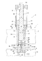
図1には、この発明に係る高精度なパンチプレス用金型1が示されている。このパンチプレス用金型1はパンチ金型3とダイ金型5とで構成されている。前記パンチ金型3としては、パンチホルダとしての上部金型支持部材7の穴7Hにはパンチガイド9が上下方向へ摺動自在に装着されている。このパンチガイド9の内部には、パンチチップ11およびこのパンチチップ11の上側に着脱可能に備えたパンチボディ13およびこのパンチボディ13にネジ部15により一体的に結合されているパンチドライバ17が上下方向(図1において上下方向)へ摺動自在に支持されている。
【0016】
前記パンチガイド9の上端部にはフランジ部19が設けられており、このフランジ部19の外周面には係止溝39が設けられており、係止溝39内には係止部材としてのOリング21が取り付けられている。前記パンチドライバ17の中央部23の外径dは下部25の外径Dに比して小さくなっており、中央部23の外側には下部25の外径Dよりも内径が小さなリテーナカラー27が上下方向へ摺動自在に設けられている。従って、リテーナカラー27はパンチドライバ17の中央部23でのみ摺動可能となっている。また、パンチドライバ17の上端部にはパンチヘッド29が取り付けられている。
【0017】
リテーナカラー27とパンチヘッド29との間には、ストリップ弾性部材として例えばストリッパスプリング31が設けられており、常時リテーナカラー27とパンチヘッド29を離す方向へ付勢している。
【0018】
リテーナカラー27およびストリッパスプリング31の外側を覆うようにして、固定部材としてのスライドカラー33が摺動自在に設けられている。このスライドカラー33の下端部内側面には、リテーナカラー27の下端部に設けられている押さえ突起35を下方へ抑えるための係止突起37が設けられており、このスライドカラー33の下端部と、パンチガイド9のフランジ部19に設けられているOリング21とが係止自在に設けられている。前記パンチガイド9のフランジ部19の下面と上部金型支持部材7の上面との間にはパンチガイド9を常時上方へ付勢したリフタスプリング20が設けられている。
【0019】
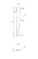
前記パンチチップ11は図2(A)、(B)および図3(A)、(B)を併せて参照するに、先端部にプレス加工部41Aを備えた適数の寸法L1の長い加工用パンチチップ41と、この加工用パンチチップ41より寸法L2(L2<L1)の短い適数の押さえ用パンチチップ43とを備えてなり、前記両チップ41、43は前記パンチボディ13に対して着脱交換可能に設けられている。
【0020】
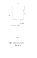
加工用パンチチップ41としては図2(A)、(B)に示されているように、頭部41Bの下端が本体41Cに対して図2(A)において左右方向へ突出部41Dを有して上下方向へ段差を有している。同様に、前記押さえ用パンチチップ43としても図3(A)、(B)に示されているように、頭部43Bの下端が本体43Cに対して図3(A)において左右方向へ突出部43Dを有して上下方向へ段差を有している。
【0021】
前記加工用パンチチップ41の幅Tは例えば1個の幅T1、2個の幅2T1などが予め準備されている。また、前記押さえ用パンチチップ43の幅Tは例えば2個の幅T1、2個の幅1.5T1、1個の幅2T1などが予め準備されている。
【0022】
前記パンチボディ13の先端部13Aには、図4および図5も併せて参照するに、先端面13Bに開口13Cを備えたパンチ装着凹部45が設けられていると共に、前記パンチボディ13の先端部13Aには、外周面に開口47Aが設けられかつ前記パンチ装着凹部45に連通した係止凹部47が設けられている。前記パンチ装着凹部45に装着されたパンチチップ11の周面に係合自在な係合面49Aを内側に形成した係止片49が、前記係止凹部47に係脱自在に設けられていると共に対称位置に一対設けられている。前記係止片49の係合面49Aは、パンチチップ11の外側面形状に対応した形状となっている。
【0023】
前記パンチチップ11である加工用パンチチップ41、押さえ用パンチチップ43の頭部41B、43Bには、前記係止凹部47に対して水平側へ突出しかつ前記係止片49の係合面49Aと係合可能の突出部41D、43Dが設けられている。なお、前記パンチボディ13の外周部にはキー53が設けられており、このキー53はパンチガイド9に形成されたキー溝9Aに嵌まり込んでいる。
【0024】
前記パンチガイド9の先端部(下端部)には十字形状のプレート55が嵌合されていると共にこのプレート55の内側には十字形状のプレート57がボルトなどで固定されている。このプレート57の先端の中央部には図6(A)、(B)も併せて参照するに、前記パンチチップ11である加工用パンチチップ41、押さえ用パンチチップ43を嵌合案内するガイド孔59Hを備えたストリッパ59が設けられている。このストリッパ59の先端部には前記ガイド孔59Hに隣接した位置に板押さえ用の突出部59Tが備えられている。
【0025】
前記ダイ金型5は、図1に示されているように、下部金型支持部材61の装着穴61Hに装着されており、ダイべース63上にダイホルダ65を介してダイ本体67がボルト69で取り付けられている。前記ダイホルダ65およびダイ本体67の中央部に設けられた穴71、73にダイチップ75が保持されていると共に着脱可能に設けられている。前記ダイチップ75は図7(A)、(B)に示されているように、先端部(上端部)に加工部77Aを備えた適数の寸法L3の加工用ダイチップ77と、この加工用ダイチップ77より寸法L4(L4<L3)より小さな適数のサブダイチップ79が図8(A)、(B)に示されているように、備えられており、前記両チップである加工用ダイチップ77とサブダイチップ79が、前記ダイ本体67に対して着脱交換可能に設けられている。
【0026】
前記加工用ダイチップ77の幅Tは例えば1個の幅T1、2個の幅2T1などが予め準備されている。また、前記サブダイチップ79の幅Tは例えば2個の幅T1、2個の幅1.5T1、1個の幅2T1などが予め準備されている。
【0027】
上記構成により、図5においてパンチチップ11である適数の加工用パンチチップ41と適数の押さえ用パンチチップ43が重ねられて例えば右側からパンチボディ13の先端部13Aに設けられたパンチ装着凹部45の先端面の開口から装着される。そして、一対の係止片49が両側から前記パンチボディ13の先端部13Aにおける外周面に開口された開口47Aに前記パンチ装着凹部45が連通して設けられた係止凹部47に装着されると、係止片49の内側に形成された係合面49Aがパンチチップ11の周面に係合される。パンチチップ11を装着したパンチボディ13をパンチガイド9に形成された穴9Hに装着せしめると、図1に示した状態になる。
【0028】
図1に示したごとく、パンチヘッド29の先端を図示省略のストライカにより打撃すると、パンチガイド9がリフタスプリング20の付勢力に抗して下降し、さらに、下降するとストリッパ59の突出部59Tの下面と加工用ダイチップ77の上面とでワークWを把持すると共に加工用ダイチップ77によりワークWの一部が下向きに切り起し曲げ製品が曲げられることになる。
【0029】
例えば図9(A)に示されているような幅T1からなる1個の加工用パンチチップ41、幅T1からなる2個の押さえ用パンチチップ43および幅T2からなる1個の押さえ用パンチチップ43と、幅T1からなる1個の加工用ダイチップ77、幅T1からなる2個のサブダイチップ79、幅1.5T1からなる2個のサブダイチップ79および幅2T1からなる2個のサブダイチップ79をそれぞれ用いると共に組み合わせて、ワークWに下向きの曲げ加工を行うと、図9(B)に示されているような下向きの切り起し曲げ製品を得ることができる。
【0030】
また、例えば図10(A)に示されているような幅T1からなる1個の加工用パンチチップ41、幅2T1からなる1個の加工用パンチチップ41および幅21Tからなる1個の押さえ用パンチチップ43と、幅T1からなる1個の加工用ダイチップ77、幅2T1からなる1個の加工用ダイチップ77、幅T1からなる2個のサブダイチップ79、幅1.5T1からなる2個のサブダイチップ79および幅2T1からなる1個のサブダイチップ79をそれぞれ用いると共に組み合わせて、ワークWに下向きの曲げ加工を行うと、図10(B)に示されているような下向きの切り起し曲げ製品を得ることができる。
【0031】
さらに、加工用パンチチップ41、押さえ用パンチチップ43と、加工用ダイチップ77、サブダイチップ79を用いると共に、幅と個数を種々組み合わせることにより、それ以外の曲げ幅と適宜な間隔の種々な曲げ製品を得ることができる。
【0032】
図11には図1に代わる他の実施形態の高精度なパンチプレス用パンチ金型81が示されている。図11において、パンチプレス用パンチ金型81はパンチ金型83とダイ金型85とで構成されている。前記パンチ金型83としては、パンチホルダとしての上部金型支持部材87の穴87Hには摺動体としてのパンチボディ89が上下方向へ摺動自在に設けられている。このパンチボディ89の上部にパンチヘッド91が取り付けられている。このパンチヘッド91の下面と前記上部金型支持部材87の上面との間にはパンチボディ89を常時上方向へ付勢したリフタスプリング93が介在されている。
【0033】
前記パンチボディ89の先端部(下端部)には十字形状のプレート95が嵌合されていると共にこのプレート95には十字形状のプレート97がボルトなどで固定されている。しかも、前記プレート95の中心部にパンチチップ99が挿入され一体化される。
【0034】
前記パンチチップ99は図12(A)、(B)および図13(A)、(B)を併せて参照するに、先端部にプレス加工部101Aを備えた適数の寸法L5の長い加工用パンチチップ101と、この加工用パンチチップ101より寸法L6(L6<L5)の短い適数の押さえ用パンチチップ103とを備えてなり、前記両チップ10、103は前記パンチボディ89に対して交換可能に設けられている。
【0035】
前記加工用パンチチップ101の幅Tは例えば1個の幅T1、2個の幅2T1および1個の幅T3などが予め準備されている。また、前記押さえ用パンチチップ103の幅Tは例えば2個の幅T1、2個の幅1.5T1、1個の幅2T1などが予め準備されている。
【0036】
前記ダイ金型85は、図1に示されているように、下部金型支持部材105の装着穴105Hに装着されており、ダイべース107上にダイホルダ109がボルト111で取り付けられている。このダイホルダ109上にはエジェクタプレート113が設けられていて、このエジェクタプレート113はダイホルダ109に対してスプリング115の付勢力により常時上方へ付勢されている。
【0037】
前記ダイホルダ109およびエジェクタプレート113の中央部に設けられた穴117、119にはダイチップ121が保持されていると共に着脱可能に設けられている。前記ダイチップ121は図14(A)、(B)に示されているように、先端部(上端部)に加工部123Aを備えた適数の寸法L7の加工用ダイチップ123と、この加工用ダイチップ123より小さな寸法L8(L8<L7)の適数のサブダイチップ125を備えてなり、前記両チップである加工用ダイチップ123とサブダイチップ125が、前記ダイホルダ109に対して着脱交換可能に設けられている。
【0038】
前記加工用ダイチップ123の幅Tは例えば1個の幅T1、2個の幅2T1および1個の幅T3などが予め準備されている。また、前記サブダイチップ125の幅Tは例えば2個の幅T1、2個の幅1.5T1、1個の幅2T1などが予め準備されている。
【0039】
上記構成により、図11に示したごとく、パンチヘッド91の先端を図示省略のストライカにより打撃すると、パンチボディ89がリフタスプリング93の付勢力に抗して下降し、さらに、下降すると加工用パンチ101の下面が前記エジェクタプレート113の上面をスプリング115の付勢力に抗して押圧して、加工用ダイチップ123の上面でワークWを上方向へ押圧するでワークWの一部に上向きの切り起し製品が曲げられることになる。
【0040】
例えば図16(A)に示されているような幅T1からなる1個の加工用パンチチップ101、幅T1からなる2個の押さえ用パンチチップ103、幅1.5T1からなる2個の押さえ用パンチチップ103および幅T2からなる1個の押さえ用パンチチップ103と、幅T1からなる1個の加工用ダイチップ123、幅T1からなる2個のサブダイチップ123、幅1.5T1からなる2個のサブダイチップ125および幅2T1からなる1個のサブダイチップ125をそれぞれ用いると共に組み合わせて、ワークWに上向きの切り起し曲げ製品の加工を行うと、図16(B)に示されているような上向きの切り起し曲げ製品を得ることができる。
【0041】
また、例えば図17(A)に示されているような幅2T1からなる2個の加工用パンチチップ101、幅T1からなる2個の押さえ用パンチチップ103、幅2T1からなる1個の加工用パンチチップ101と、幅2T1からなる2個の加工用ダイチップ123、幅T1からなる2個のサブダイチップ125および幅2T1からなる1個のサブダイチップ125をそれぞれ用いると共に組み合わせて、ワークWに上向きの切り起し曲げ製品の曲げ加工を行うと、図17(B)に示されているような上向きの切り起し曲げ曲げ製品を得ることができる。
【0042】
さらに、加工用パンチチップ101、押さえ用パンチチップ103と、加工用ダイチップ123、サブダイチップ125を用いると共に、幅と個数を種々組み合わせることにより、それ以外の曲げ幅と適宜な間隔の種々な曲げ製品を得ることができる。
【0043】
なお、この発明は前述した実施の形態に限定されることなく、適宜な変更を行うことによりその他の態様で実施し得るものである。
【0044】
【発明の効果】
以上のごとき発明の実施の形態の説明から理解されるように、請求項1〜5の発明によるパンチプレス用金型によれは、加工用パンチチップ、押さえ用パンチチップと、加工用ダイチップ、サブダイチップとを適宜組み合わせて用いることで、ワークの一部分に、下向きまたは上向きの切り起こしの曲げ製品の加工を行うことができる。また、上記の各チップ幅を選択することで、曲げ製品の幅と間隔を自由に選択できると共に種々の曲げ幅の曲げ製品に応じてパンチチップとダイチップを交換して加工を行うことができる。
【0045】
また、下向きの切り起こし曲げの加工を行うときには、ストリッパの先端部に備えられた突出部と押さえ用パンチチップとでワークを押さえることができ、高精度な曲げ製品を得ることができる。
【図面の簡単な説明】
【図1】この発明を実施するためのパンチプレス用金型正面断面図である。
【図2】(A)、(B)は下向き用の加工用パンチチップの正面断面図、底面図である。
【図3】(A)、(B)は下向き用の押さえ用パンチチップの正面断面図、底面図である。
【図4】 パンチボディの先端部にパンチチップを係脱せしめる構造の分解斜視図である。
【図5】パンチボディの先端部にパンチチップを係脱せしめる構造の分解正面図である。
【図6】(A)、(B)はストリッパの正面断面図、底面図である。
【図7】(A)、(B)は下向き用の加工用ダイチップの正面断面図、平面図である。
【図8】(A)、(B)は下向き用のサブダイチップの正面断面図、平面図である。
【図9】(A)は下向き用の加工用パンチチップ、押さえ用パンチチップと加工用ダイチップ、サブダイチップを組み合わせ一例の側面図で、(A)の金型を用いて下向きの曲げ製品を加工した一例のワークの斜視図である。
【図10】(A)は加工用パンチチップ、押さえ用パンチチップと加工用ダイチップ、サブダイチップを組み合わせ一例の側面図で、(A)の金型を用いて下向きの曲げ製品を加工した他例のワークの斜視図である。
【図11】図1に代わる他の実施形態のパンチプレス用金型正面断面図である。
【図12】 (A)、(B)は上向き用の加工用パンチチップの正面断面図、底面図である。
【図13】(A)、(B)は上向き用の押さえ用パンチチップの正面断面図、底面図である。
【図14】(A)、(B)は上向き用の加工用ダイチップの正面断面図、平面図である。
【図15】(A)、(B)は下向き用のサブダイチップの正面断面図、平面図である。
【図16】(A)は上向き用の加工用パンチチップ、押さえ用パンチチップと加工用ダイチップ、サブダイチップを組み合わせ一例の側面図で、(A)の金型を用いて上向きの曲げ製品を加工した一例のワークの斜視図である。
【図17】(A)は上向き用の加工用パンチチップ、押さえ用パンチチップと加工用ダイチップ、サブダイチップを組み合わせ一例の側面図で、(A)の金型を用いて上向きの曲げ製品を加工した他例のワークの斜視図である。
【符号の説明】
1 パンチプレス用金型
3 パンチ金型
5 ダイ金型
7 上部金型支持部材(パンチホルダ)
9 パンチガイド
11 パンチチップ
13 パンチボディ
20 リフタスプリング
29 パンチヘッド
35 押さえ突起
37 係止突起
39 係止溝
41 加工用パンチチップ
41A プレス加工部
43 押さえ用パンチチップ
55 プレート
57 プレート
59 ストリッパ
59T 突出部
61 下部金型支持部材
63 ダイベース
65 ダイホルダ
67 ダイ本体
75 ダイチップ
77 加工用ダイチップ
77A 加工部
79 サブダイチップ
81 パンチプレス用金型
83 パンチ金型
85 ダイ金型
87 上部金型支持部材(パンチホルダ)
89 パンチボディ(摺動体)
91 パンチヘッド
93 リフタスプリング
95 プレート
97 プレート
99 パンチチップ
101 加工用パンチチップ
103 押さえ用パンチチップ
105 下部金型支持部材
107 ダイベース
109 ダイ本体
113 エジェクタプレート
115 スプリング
121 ダイチップ
123 加工用ダイチップ
123A 加工部
125 サブダイチップ[0001]
BACKGROUND OF THE INVENTION
The present invention relates to a die for a punch press that performs highly accurate downward or upward cut-and-bend bending on a workpiece for manufacturing an electronic component, for example.
[0002]
[Prior art]
Conventionally, for example, when processing a downward or upward cut and bent product on a part of a workpiece for manufacturing an electronic component, for example, a dedicated punch die or die die is used according to the width of each bent product. Many are created and exchanged each time.
[0003]
[Problems to be solved by the invention]
By the way, in the case of the above-described dedicated mold, it is necessary to prepare and prepare a number of appropriate molds according to the width of each bent product, and it is difficult to cope with it. There was a problem that the width was not free.
[0004]
The present invention has been made to solve the above-described problems, and an object of the present invention is to provide a punch press mold in which the width of each downwardly or upwardly bent product can be freely set. .
[0005]
[Means for Solving the Problems]
In order to achieve the above object, the invention described in claim 1 is a punch press mold in which a punch body assembly is slidably fitted in a cylindrical punch guide, and the punch body assembly includes: A punch mounting recess is provided at the tip of the punch body, and a pair of locking recesses that open to both sides of the outer peripheral surface of the punch body are provided in communication with the punch mounting recess, and are detachably mounted on the punch mounting recess. A pair of engaging pieces having an engaging surface that can be engaged with the outer peripheral surface of the punch tip and an engaging surface that engages with a protrusion formed on the head of the punch tip can be attached to and detached from the engaging recess. An appropriate number of long processing punch tips, each of which has a press working portion at the tip, and an appropriate number of pressing punches shorter than the processing punch tip. Like chips A stripper provided with a guide hole for fitting and guiding the punching tip for pressing and the punching tip for pressing on the tip side of the punch guide, and a plate at a position adjacent to the guide hole at the tip of the stripper. It is characterized by comprising a pressing protrusion .
[0006]
According to a second aspect of the present invention, in the punch press die according to the first aspect, at least one of the processing punch tip or the pressing punch tip is divided into a plurality of portions .
[0007]
According to a third aspect of the present invention, there is provided a punch press mold in which a die body holding a die chip is attached to a die base, wherein the die chip includes an appropriate number of processing die chips each having a processing portion at a tip portion thereof, and the processing An appropriate number of sub-die chips smaller in size than the die chip are provided, and at least one of the processing die chip or the sub-die chip is divided into a plurality and provided so as to be attachable / detachable with respect to the die body. It is a feature .
[0008]
According to a fourth aspect of the present invention, the tip of the sliding body that is slidably supported by the punch holder in the punch press is provided with a punch tip for performing press working, and the punch tip is pressed at the tip. An appropriate number of long processing punch tips provided with a portion and an appropriate number of pressing punch tips shorter than the processing punch tip, both the tips being provided to be detachable and replaceable with respect to the sliding body. It is characterized by being .
[0009]
According to a fifth aspect of the present invention, in the punch press die according to the fourth aspect, at least one of the processing punch tip or the pressing punch tip is divided into a plurality of portions. .
[0012]
Therefore, according to the punch press die of the invention described in claims 1 to 5, by using an appropriate combination of a processing punch tip, a pressing punch tip, a processing die tip, and a sub die tip, A portion of the cut can be bent downward or upward. In addition, by selecting the width of each of the above chips, the bending width and the interval can be freely selected, and the punch chip and the die chip can be exchanged in accordance with bending products having various bending widths. .
[0013]
Further, when performing the downward cut-and-raise bending process, the workpiece is pushed by the protrusion provided at the tip of the stripper and the pressing punch tip, and a highly accurate bending product is obtained.
[0014]
DETAILED DESCRIPTION OF THE INVENTION
Hereinafter, embodiments of the present invention will be described in detail with reference to the drawings.
[0015]
FIG. 1 shows a highly accurate punch press mold 1 according to the present invention. The punch press die 1 is composed of a punch die 3 and a die die 5. As the
[0016]
A
[0017]
For example, a
[0018]
A slide collar 33 as a fixing member is slidably provided so as to cover the outside of the
[0019]
The
[0020]
As shown in FIGS. 2 (A) and 2 (B), the lower end of the
[0021]
As the width T of the
[0022]
4A and 4B, the
[0023]
The
[0024]
A
[0025]
As shown in FIG. 1, the die mold 5 is mounted in the mounting
[0026]
As the width T of the processing die
[0027]
With the above-described configuration, the punch mounting recess provided in the
[0028]
As shown in FIG. 1, when the tip of the
[0029]
For example, as shown in FIG. 9A, one
[0030]
Further, for example, as shown in FIG. 10A, one
[0031]
Furthermore, by using the
[0032]
FIG. 11 shows a punch die 81 for a high precision punch press according to another embodiment instead of FIG. In FIG. 11, a punch press punch die 81 includes a
[0033]
A
[0034]
The
[0035]
For example, one width T1, two widths 2T1, and one width T3 are prepared in advance as the width T of the
[0036]
As shown in FIG. 1, the
[0037]
A
[0038]
As the width T of the
[0039]
With the above configuration, as shown in FIG. 11, when the tip of the
[0040]
For example, as shown in FIG. 16A, one
[0041]
Further, for example, as shown in FIG. 17A, two processing
[0042]
Furthermore, by using the
[0043]
In addition, this invention is not limited to embodiment mentioned above, It can implement in another aspect by making an appropriate change.
[0044]
【The invention's effect】
As can be understood from the description of the embodiments of the invention as described above, the punch press die according to the inventions of claims 1 to 5 includes a processing punch tip, a pressing punch tip, a processing die chip, a sub By using an appropriate combination with a die chip, it is possible to process a downward or upward bent product on a part of the workpiece. Further, by selecting the above chip widths, the width and interval of the bent products can be freely selected, and the punch chip and the die chip can be exchanged according to the bent products having various bending widths.
[0045]
Further, when performing the downward cut-and-raise bending process, the workpiece can be pressed by the protrusion provided at the tip of the stripper and the pressing punch tip, and a highly accurate bending product can be obtained.
[Brief description of the drawings]
FIG. 1 is a front sectional view of a punch press mold for carrying out the present invention.
FIGS. 2A and 2B are a front sectional view and a bottom view of a punching chip for processing downward.
FIGS. 3A and 3B are a front sectional view and a bottom view of a downward pressing punch tip, respectively.
FIG. 4 is an exploded perspective view of a structure in which a punch tip is engaged with and disengaged from a distal end portion of a punch body.
FIG. 5 is an exploded front view of a structure in which a punch tip is engaged with and disengaged from a front end portion of a punch body.
6A and 6B are a front sectional view and a bottom view of a stripper.
FIGS. 7A and 7B are a front sectional view and a plan view of a downward processing die chip, respectively.
8A and 8B are a front sectional view and a plan view of a downward-facing sub die chip, respectively.
FIG. 9A is a side view of an example of a combination of a downward processing punch tip, a pressing punch tip and a processing die chip, and a sub die chip. FIG. 9A shows a downward bent product using the mold of FIG. It is a perspective view of an example work processed.
FIG. 10A is a side view of an example of a combination of a processing punch tip, a pressing punch tip and a processing die chip, and a sub die chip, in which a downward bending product is processed using the mold of FIG. It is a perspective view of an example work.
11 is a front sectional view of a punch press die according to another embodiment instead of FIG. 1. FIG.
FIGS. 12A and 12B are a front cross-sectional view and a bottom view of an upward-facing punch tip for machining. FIGS.
FIGS. 13A and 13B are a front sectional view and a bottom view of an upward pressing punch tip, respectively.
14A and 14B are a front sectional view and a plan view of an upward processing die chip, respectively.
15A and 15B are a front sectional view and a plan view of a downward-facing sub die chip, respectively.
FIG. 16A is a side view of an example of a combination of an upward processing punch tip, a pressing punch tip, a processing die chip, and a sub die chip, and an upward bending product using the mold of FIG. It is a perspective view of an example work processed.
FIG. 17A is a side view of an example of a combination of an upward processing punch tip, a pressing punch tip and a processing die chip, and a sub die chip, and shows an upward bent product using the mold of FIG. It is a perspective view of the workpiece of other examples processed.
[Explanation of symbols]
1
9
89 Punch body (sliding body)
91
Claims (5)
Priority Applications (6)
| Application Number | Priority Date | Filing Date | Title |
|---|---|---|---|
| JP2002172740A JP4133005B2 (en) | 2002-06-13 | 2002-06-13 | Die for punch press |
| PCT/JP2003/007504 WO2003106067A1 (en) | 2002-06-13 | 2003-06-12 | Punch press die |
| DE2003620261 DE60320261T2 (en) | 2002-06-13 | 2003-06-12 | MATRIZE OF A PUNCHING PRESS |
| US10/516,316 US7225659B2 (en) | 2002-06-13 | 2003-06-12 | Punch press die |
| EP03733389A EP1529576B1 (en) | 2002-06-13 | 2003-06-12 | Punch press die |
| TW92115937A TWI222905B (en) | 2002-06-13 | 2003-06-12 | Die for punch press |
Applications Claiming Priority (1)
| Application Number | Priority Date | Filing Date | Title |
|---|---|---|---|
| JP2002172740A JP4133005B2 (en) | 2002-06-13 | 2002-06-13 | Die for punch press |
Publications (2)
| Publication Number | Publication Date |
|---|---|
| JP2004017062A JP2004017062A (en) | 2004-01-22 |
| JP4133005B2 true JP4133005B2 (en) | 2008-08-13 |
Family
ID=29727878
Family Applications (1)
| Application Number | Title | Priority Date | Filing Date |
|---|---|---|---|
| JP2002172740A Expired - Fee Related JP4133005B2 (en) | 2002-06-13 | 2002-06-13 | Die for punch press |
Country Status (6)
| Country | Link |
|---|---|
| US (1) | US7225659B2 (en) |
| EP (1) | EP1529576B1 (en) |
| JP (1) | JP4133005B2 (en) |
| DE (1) | DE60320261T2 (en) |
| TW (1) | TWI222905B (en) |
| WO (1) | WO2003106067A1 (en) |
Cited By (1)
| Publication number | Priority date | Publication date | Assignee | Title |
|---|---|---|---|---|
| CN107186047A (en) * | 2017-06-05 | 2017-09-22 | 湖南七纬科技有限公司 | A kind of aluminium alloy extrusions processing blanking die |
Families Citing this family (10)
| Publication number | Priority date | Publication date | Assignee | Title |
|---|---|---|---|---|
| US7610838B2 (en) * | 2007-03-30 | 2009-11-03 | Staples The Office Superstore, Llc | Hole punch |
| TWI409656B (en) * | 2007-12-31 | 2013-09-21 | Hon Hai Prec Ind Co Ltd | System and method for outspreading an irregular curve of a part of a punching die |
| CN101569908B (en) | 2008-04-28 | 2013-11-06 | 鸿富锦精密工业(深圳)有限公司 | Stamping die |
| DE102010006939A1 (en) | 2010-02-04 | 2011-08-04 | Voxeljet Technology GmbH, 86167 | Device for producing three-dimensional models |
| USD669936S1 (en) | 2011-05-25 | 2012-10-30 | Staples The Office Superstore, Llc | Hole punch |
| USD736280S1 (en) * | 2012-04-11 | 2015-08-11 | Milwaukee Electric Tool Corporation | Die |
| CN102632129A (en) * | 2012-04-16 | 2012-08-15 | 江苏金方圆数控机床有限公司 | Contactless cutting mould for numerical control turret punch press |
| DE102015116562A1 (en) * | 2015-09-30 | 2017-03-30 | Tkr Spezialwerkzeuge Gmbh | Hydraulic punching device as well as punching punch carrier for punching device |
| CN110280646B (en) * | 2019-07-23 | 2023-12-22 | 西安工业大学 | Cold stamping die |
| CN114951864B (en) * | 2022-07-13 | 2022-11-25 | 杭州爱新凯科技有限公司 | Punching needle processing method of micro-punching machine and micro-punching machine |
Family Cites Families (20)
| Publication number | Priority date | Publication date | Assignee | Title |
|---|---|---|---|---|
| US1402284A (en) * | 1918-05-29 | 1922-01-03 | George H Daniels | Sectional die |
| US1449385A (en) * | 1919-05-20 | 1923-03-27 | Ludwig M Dieterich | Art and apparatus for forcing material into a predetermined form |
| US1468271A (en) * | 1921-04-18 | 1923-09-18 | American Multigraph Co | Mechanism for making printing-strip holders |
| US1939503A (en) * | 1929-02-11 | 1933-12-12 | Guardian Trust Company Of Detr | Tool holder |
| US2017247A (en) * | 1934-10-17 | 1935-10-15 | George A Vis | Tool attachment |
| US3100411A (en) * | 1959-04-22 | 1963-08-13 | Carrick Prec Tools Ltd | Press tools |
| US3077135A (en) * | 1960-02-29 | 1963-02-12 | Henn Harry Walther | Close center slot perforating device |
| US3690209A (en) * | 1969-09-25 | 1972-09-12 | Robert J Gargrave | Die-assembly |
| JPS6277124A (en) * | 1985-09-30 | 1987-04-09 | Ohashi Seisakusho:Kk | Press metal die for punching and burring |
| JP2647405B2 (en) * | 1988-01-22 | 1997-08-27 | 株式会社協豊製作所 | Press working method with drilling, apparatus therefor and punch for the working method |
| JP2837719B2 (en) * | 1989-12-18 | 1998-12-16 | 株式会社アマダメトレックス | Mold for punch press |
| JP2627354B2 (en) | 1990-07-23 | 1997-07-02 | 三洋電機株式会社 | Magnetic sensors and magnetic rotary encoders |
| JP2548763Y2 (en) * | 1990-11-28 | 1997-09-24 | 株式会社アマダ | Turret punch press |
| JP2578289B2 (en) * | 1992-04-08 | 1997-02-05 | 株式会社アマダメトレックス | Louver mold |
| JP2545176B2 (en) * | 1992-05-19 | 1996-10-16 | 株式会社アマダメトレックス | Mold for punching machine |
| JP2611089B2 (en) * | 1992-06-30 | 1997-05-21 | 株式会社アマダメトレックス | Mold for molding |
| US5661993A (en) * | 1995-05-22 | 1997-09-02 | Tee-Lok Corporation | Punch tool and method for manufacturing truss plates |
| US6189361B1 (en) * | 1997-09-04 | 2001-02-20 | Amada Metrecs Company Limited | Tool for forming protrusions in material by cutting and deforming |
| JP3722258B2 (en) * | 1998-09-25 | 2005-11-30 | 日本碍子株式会社 | Punching device for punching, punch for punching, and method for manufacturing punch for punching |
| JP2001062784A (en) * | 1999-08-27 | 2001-03-13 | Ngk Insulators Ltd | Method for punching fragile material and punching die used for the same |
-
2002
- 2002-06-13 JP JP2002172740A patent/JP4133005B2/en not_active Expired - Fee Related
-
2003
- 2003-06-12 WO PCT/JP2003/007504 patent/WO2003106067A1/en active IP Right Grant
- 2003-06-12 TW TW92115937A patent/TWI222905B/en not_active IP Right Cessation
- 2003-06-12 EP EP03733389A patent/EP1529576B1/en not_active Expired - Fee Related
- 2003-06-12 US US10/516,316 patent/US7225659B2/en not_active Expired - Fee Related
- 2003-06-12 DE DE2003620261 patent/DE60320261T2/en not_active Expired - Lifetime
Cited By (1)
| Publication number | Priority date | Publication date | Assignee | Title |
|---|---|---|---|---|
| CN107186047A (en) * | 2017-06-05 | 2017-09-22 | 湖南七纬科技有限公司 | A kind of aluminium alloy extrusions processing blanking die |
Also Published As
| Publication number | Publication date |
|---|---|
| DE60320261D1 (en) | 2008-05-21 |
| US20050217343A1 (en) | 2005-10-06 |
| TWI222905B (en) | 2004-11-01 |
| EP1529576B1 (en) | 2008-04-09 |
| EP1529576A4 (en) | 2007-04-04 |
| DE60320261T2 (en) | 2009-05-20 |
| WO2003106067A1 (en) | 2003-12-24 |
| TW200405830A (en) | 2004-04-16 |
| EP1529576A1 (en) | 2005-05-11 |
| JP2004017062A (en) | 2004-01-22 |
| US7225659B2 (en) | 2007-06-05 |
Similar Documents
| Publication | Publication Date | Title |
|---|---|---|
| JP4133005B2 (en) | Die for punch press | |
| JP4279532B2 (en) | Mold apparatus and lower mold for use in processing method of molded product | |
| CN105382068B (en) | The device and method of the cut surface with burr on finishing stamping parts or fine part | |
| JP2003181569A (en) | Pressing die | |
| CN211191673U (en) | One-time stamping forming's cell-phone shell mould | |
| JPH0375247B2 (en) | ||
| JP4812307B2 (en) | Burring mold and burring method | |
| JP4753396B1 (en) | Mold equipment | |
| CN213495901U (en) | Die-cut mould and die-cut equipment of die casting | |
| CN210701996U (en) | Stamping die and stamping equipment | |
| CN210877138U (en) | Stamping die slider mechanism convenient to take off material | |
| JPH0910860A (en) | Press punching device | |
| CN210586694U (en) | Cam fine blanking die | |
| CN203184417U (en) | Folded forming die for car trunk lock catch | |
| JP2600475B2 (en) | Panel cutting molding machine | |
| JP2591391B2 (en) | Punching die | |
| CN217252133U (en) | General drawing die for common stamping machine tool and automatic stamping machine tool | |
| JP4390316B2 (en) | Die equipment | |
| CN213436560U (en) | Hardware mould punching device | |
| CN211360302U (en) | Double-station punching and bending forming die for pipe parts | |
| CN210614791U (en) | Baffle blanking mould | |
| CN216175832U (en) | One-step forming die | |
| CN211247957U (en) | Stamping die is used in middle part shaping processing of casing behind booster | |
| CN212792687U (en) | Compressor main body stamping die | |
| CN212857378U (en) | Forming die of complicated curved member |
Legal Events
| Date | Code | Title | Description |
|---|---|---|---|
| A621 | Written request for application examination |
Free format text: JAPANESE INTERMEDIATE CODE: A621 Effective date: 20050531 |
|
| A131 | Notification of reasons for refusal |
Free format text: JAPANESE INTERMEDIATE CODE: A131 Effective date: 20080219 |
|
| A521 | Written amendment |
Free format text: JAPANESE INTERMEDIATE CODE: A523 Effective date: 20080319 |
|
| TRDD | Decision of grant or rejection written | ||
| A01 | Written decision to grant a patent or to grant a registration (utility model) |
Free format text: JAPANESE INTERMEDIATE CODE: A01 Effective date: 20080509 |
|
| A01 | Written decision to grant a patent or to grant a registration (utility model) |
Free format text: JAPANESE INTERMEDIATE CODE: A01 |
|
| A61 | First payment of annual fees (during grant procedure) |
Free format text: JAPANESE INTERMEDIATE CODE: A61 Effective date: 20080602 |
|
| FPAY | Renewal fee payment (event date is renewal date of database) |
Free format text: PAYMENT UNTIL: 20110606 Year of fee payment: 3 |
|
| R150 | Certificate of patent or registration of utility model |
Free format text: JAPANESE INTERMEDIATE CODE: R150 |
|
| FPAY | Renewal fee payment (event date is renewal date of database) |
Free format text: PAYMENT UNTIL: 20120606 Year of fee payment: 4 |
|
| FPAY | Renewal fee payment (event date is renewal date of database) |
Free format text: PAYMENT UNTIL: 20120606 Year of fee payment: 4 |
|
| FPAY | Renewal fee payment (event date is renewal date of database) |
Free format text: PAYMENT UNTIL: 20130606 Year of fee payment: 5 |
|
| FPAY | Renewal fee payment (event date is renewal date of database) |
Free format text: PAYMENT UNTIL: 20140606 Year of fee payment: 6 |
|
| S533 | Written request for registration of change of name |
Free format text: JAPANESE INTERMEDIATE CODE: R313533 |
|
| R350 | Written notification of registration of transfer |
Free format text: JAPANESE INTERMEDIATE CODE: R350 |
|
| LAPS | Cancellation because of no payment of annual fees |