EP1529576A1 - Punch press die - Google Patents
Punch press die Download PDFInfo
- Publication number
- EP1529576A1 EP1529576A1 EP03733389A EP03733389A EP1529576A1 EP 1529576 A1 EP1529576 A1 EP 1529576A1 EP 03733389 A EP03733389 A EP 03733389A EP 03733389 A EP03733389 A EP 03733389A EP 1529576 A1 EP1529576 A1 EP 1529576A1
- Authority
- EP
- European Patent Office
- Prior art keywords
- punch
- tips
- forming
- die
- tip
- Prior art date
- Legal status (The legal status is an assumption and is not a legal conclusion. Google has not performed a legal analysis and makes no representation as to the accuracy of the status listed.)
- Granted
Links
Images


Classifications
-
- B—PERFORMING OPERATIONS; TRANSPORTING
- B21—MECHANICAL METAL-WORKING WITHOUT ESSENTIALLY REMOVING MATERIAL; PUNCHING METAL
- B21D—WORKING OR PROCESSING OF SHEET METAL OR METAL TUBES, RODS OR PROFILES WITHOUT ESSENTIALLY REMOVING MATERIAL; PUNCHING METAL
- B21D28/00—Shaping by press-cutting; Perforating
- B21D28/02—Punching blanks or articles with or without obtaining scrap; Notching
- B21D28/10—Incompletely punching in such a manner that the parts are still coherent with the work
-
- B—PERFORMING OPERATIONS; TRANSPORTING
- B21—MECHANICAL METAL-WORKING WITHOUT ESSENTIALLY REMOVING MATERIAL; PUNCHING METAL
- B21D—WORKING OR PROCESSING OF SHEET METAL OR METAL TUBES, RODS OR PROFILES WITHOUT ESSENTIALLY REMOVING MATERIAL; PUNCHING METAL
- B21D28/00—Shaping by press-cutting; Perforating
- B21D28/24—Perforating, i.e. punching holes
- B21D28/34—Perforating tools; Die holders
-
- B—PERFORMING OPERATIONS; TRANSPORTING
- B21—MECHANICAL METAL-WORKING WITHOUT ESSENTIALLY REMOVING MATERIAL; PUNCHING METAL
- B21D—WORKING OR PROCESSING OF SHEET METAL OR METAL TUBES, RODS OR PROFILES WITHOUT ESSENTIALLY REMOVING MATERIAL; PUNCHING METAL
- B21D37/00—Tools as parts of machines covered by this subclass
- B21D37/02—Die constructions enabling assembly of the die parts in different ways
-
- Y—GENERAL TAGGING OF NEW TECHNOLOGICAL DEVELOPMENTS; GENERAL TAGGING OF CROSS-SECTIONAL TECHNOLOGIES SPANNING OVER SEVERAL SECTIONS OF THE IPC; TECHNICAL SUBJECTS COVERED BY FORMER USPC CROSS-REFERENCE ART COLLECTIONS [XRACs] AND DIGESTS
- Y10—TECHNICAL SUBJECTS COVERED BY FORMER USPC
- Y10T—TECHNICAL SUBJECTS COVERED BY FORMER US CLASSIFICATION
- Y10T83/00—Cutting
- Y10T83/929—Tool or tool with support
- Y10T83/9411—Cutting couple type
- Y10T83/9423—Punching tool
- Y10T83/9428—Shear-type male tool
- Y10T83/943—Multiple punchings
Definitions
- the present invention relates to a punch press tool that is used for forming a workpiece precisely, which is to be used for, for example, electronic parts, through a process consisting of upward or downward cut-and-raising and bending.
- a punch tool or die tool is made corresponding to the width of the bent part, and such tools are exchanged to be used for different widths.
- the present invention is intended to solve the problems described above, and an object of the invention is to provide a punch press tool that is capable of forming a bent part with a freely-designed width by downward or upward cut-and-raising and bending.
- a punch press tool comprises: a cylindrical punch guide; a punch body fitted slidably within the aforesaid punch guide; and a punch tip to perform press forming; wherein the aforesaid punch tip includes an appropriate number of long forming punch tips each including a press forming portion in the leading portion thereof and an appropriate number of clamping punch tip each having a shorter length compared with the forming punch tips; and both of the aforesaid tips are attached to the aforesaid punch body detachably and exchangeably.
- a punch press tool is a punch press tool of the first aspect in which at least either the aforesaid forming punch tips and the aforesaid clamping punch tips are split into a plurality.
- a punch press tool is a punch press tool according to the first or the second aspect in which provided is a stripper having a guide hole for receiving and guiding both of the aforesaid tips in the leading end side of the aforesaid punch guide and provided is a projected portion for clamping a workpiece in a position adjacent to the aforesaid guide hole located in the leading end of the aforesaid stripper.
- a punch press tool comprises: a die base; a die body supported on the aforesaid die base; and a die tip held in the aforesaid die body; wherein the aforesaid die tip comprises an appropriate number of forming die tips each including a forming portion in the leading end thereof and an appropriate number of sub die tips each having a smaller size compared with the forming die tips; and both of the aforesaid tips are attached to the aforesaid die body detachably and exchangeably.
- a punch press tool is a punch press tool according to the fourth aspect in which at least either the aforesaid forming die tips or the sub die tips are split into a plurality.
- a punch press tool comprises: a punch holder for the punch press; a sliding body supported slidably within the aforesaid punch holder; and a punch tip for performing press forming, which punch tip is attached to the leading end of the aforesaid sliding body; wherein the aforesaid punch tip includes an appropriate number of long forming punch tips each including a press forming portion in the leading end thereof and an appropriate number of clamping punch tips each having a shorter length compared with the forming punch tips; and the aforesaid forming punch tips and the aforesaid clamping punch tip are attached to the aforesaid sliding body detachably and exchangeably.
- a punch press tool is a punch press tool according to the sixth aspect in which at least either the aforesaid forming punch tips or the aforesaid clamping punch tips are split into a plurality.
- a downward or upward cut-and-raised and bent part can be formed in a portion of a workpiece.
- the width and the spacing of a bent part can be selected freely, and the punch tips and the die tips can be exchanged for forming various bent parts having various bent width.
- the workpiece when forming into a downward cut-and-raised and bent part in a workpiece, the workpiece can be clamped between the projected portion provided in the leading end of the stripper and the clamping punch tip, so that a bent part can be obtained with high accuracy.
- FIG. 1 shows a punch press tool 1 of high precision according to the present invention.
- This punch press tool 1 is constructed of a punch tool 3 and a die tool 5.
- a punch guide 9 is provided to be slidable upward and downward within a hole 7H formed in a upper die supporting member 7 that serves as a punch holder.
- This flange portion 19 includes a locking groove 39 formed on a circumference surface thereof, and an O ring 21 as a locking member is inserted into the locking groove 39.
- the aforesaid punch driver 17 consists of a middle portion 23 with an outer diameter d and a lower portion 25 with an outer diameter 25, in which the outer diameter d is adapted to be smaller than the outer diameter D.
- a retainer collar 27 having an inner diameter smaller than the outer diameter D of the lower portion 25 is provided slidably upward and downward outside the middle portion 23. Accordingly, the retainer collar 27 is slidable along only the middle portion 23 of the punch driver 17. Further, a punch head 29 is mounted on the upper end of the punch driver 17.
- a resiliently stripping member such as a stripper spring 31 is provided for constantly biasing the retainer collar 27 and punch head 29 to press them apart.
- a slide collar 33 Surrounding the peripheries of the retainer collar 27 and the stripper spring 31, a slide collar 33 that servers as a fixing member is disposed slidably. On the internal surface of the lower end of the slide collar 33, a locking projection 37 is formed. This locking projection 37 serves to press downward a clamping projection 35 formed in the lower end of the retainer collar 27 so as to allow the lower end of the slide collar 33 to engage lockably the O-ring 21 disposed in the flange portion 19 of the punch guide 9. Between the flange portion 19 of the aforesaid punch guide 9 and the upper surface of the upper die supporting member 7, a lifter spring 20 is disposed for biasing upward the punch guide 9 constantly.
- the aforesaid punch tip 11 comprises an appropriate number of forming punch tips 41 each of which includes a press forming portion in the leading end portion thereof and has a length L1 and an appropriate number of clamping punch tips 43 each of which has a shorter length L2 compared with that of the forming punch tip 41 (L2 ⁇ L1). Both tips 41 and 43 are received in the aforesaid punch body 13 detachably.
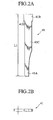
- FIG. 2A and FIG. 2B show the forming punch tip 41.
- the head portion 41B has projections 41D in the bottom thereof, which projections project toward right and left with respect to the body portion 41C so as to make a step in the vertical direction.
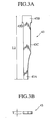
- FIG. 3A and FIG. 3B show the aforesaid clamping punch tip 43.
- the head portion 43B has projections 43D in the bottom thereof, which projections project toward right and left with respect to the body portion 43C so as to make a step in the vertical direction.
- the aforesaid forming punch tips 41 are prepared preliminarily with various widths T such as the width T1 for one piece and the width 2T1 for two pieces.
- the aforesaid clamping punch tips 43 are prepared preliminarily with various widths T such as the width T1 for two pieces, the width 1.5T1 for two pieces and the width 2T1 for one piece.
- a punch receiving recess 45 including an opening 13C is formed in the leading end surface 13B.
- locking recesses 47 including openings 47A formed on the periphery surfaces thereof and communicating with the aforesaid punch receiving recess 45 are formed.
- a locking piece 49 is provided with an engaging surface 49A in an inner side thereof, which is adapted to be engageable with a peripheral surface of the punch tip 11 attached inside the aforesaid punch receiving recess 45.
- the locking piece 49 is disposed detachably in one of the aforesaid locking recesses 47, and the paired locking piece is disposed in the other locking recess located oppositely to the foregoing locking recess.
- the engaging surface 49A of the aforesaid locking piece 49 is formed with the shape corresponding to a shape of the outer periphery of the punch tip 11.
- the forming punch tip 41 and the clamping punch tip 43 both of which compose the aforesaid punch tip 11, are provided with the projections 41D and 43D respectively on the respective head portions 41B and 43B thereof, which projections project horizontally with respect to the aforesaid locking recess 47 and are engageable with the engaging surface 49A of the aforesaid locking piece 49.
- the aforesaid punch body 13 is provided with a key 53 in the peripheral surface thereof, and this key 53 is received in a key groove 9A that is formed on the punch guide 9.
- a cross-shaped plate 55 is fitted, and inside this plate 55 a cross-shaped plate 57 is fixed by means of a bolt or the like.
- a stripper 59 is disposed, which stripper is formed with a guide hole 59H for receiving and guiding the aforesaid punch tip 11 composed of the forming punch tips 41 and the clamping punch tips 43.
- a projected portion 59T is disposed adjacent to the aforesaid guide hole 59H, which projected portion serves for clamping the work sheet.
- the aforesaid die tool 5 is, as shown in FIG. 1, mounted within a mounting hole 61H disposed in the lower die supporting member 61, and a die body 67 is supported on a die base 63 via a die holder 65 and fastened by means of a bolt 69.
- a die tip 75 is held detachably.
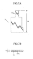
- the aforesaid die tip 75 comprises an appropriate number of the forming die tips 77, which have a size L3, having a forming portion 77A as shown in FIG. 7A and FIG.
- Such tips i.e., the forming die tips 77 and the sub die tips 79 are disposed detachably and exchangeably in the aforesaid die body 67.
- the aforesaid forming die tips 77 are prepared preliminarily with various widths T such as width T1 for one piece and width 2T1 for two pieces. Also, the aforesaid sub die tips 79 are prepared preliminarily with various widths such as width T1 for two pieces, width 1.5T1 for two pieces and width 2T1 for one piece.
- the appropriate number of forming punch tips 41 and the appropriate number of clamping punch tips 43 are bound together to form the punch tip 11.
- Such bound tips are inserted from the right in the figure into an opening formed in the leading end surface of the punch receiving recess 45 that is disposed in the leading end portion 13A of the punch body 13.
- the locking pieces 49 are mounted within the locking recess 47, which is formed in such a manner that the openings 47A formed on the peripheral surface of the leading end portion 13A of the aforesaid punch body 13 communicate with the aforesaid punch receiving recess 45, the engaging surface 49 formed in the inner side of the locking piece 49 comes to engage the peripheral surface of the punch tip 11.
- the punch body 13 including the punch tip 11 is accommodated in the hole 9H formed in the punch guide 9, which is shown in Fig. 1.
- the punch guide 9 moves downward against the bias of the lifter spring 20. While the punch guide 9 moves downward further, the lower surface of the projected portion 59T of the stripper 59 and the upper surface of the forming die tip 77 hold the workpiece cooperatively, and the forming die tip 77 performs to cut-and-raise and to bend downward for forming a bent part.
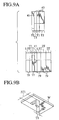
- one piece of the forming punch tip 41 with the width T1, two pieces of the clamping punch tips 43 with the width T1 and one piece of the clamping punch tip 43 with the width T2, and one piece of the forming die tip 77 with the width T1, two pieces of the sub die tips 79 with the width T1, two pieces of the sub die tips 79 with the width 1.5T1 and two pieces of the sub die tips 79 with the width 2T1 are combined together into two sets. And when such combinations are used for bending a workpiece downward, a downward cut-and-raised and bent part can be obtained as shown in FIG. 9B.
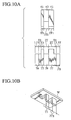
- one piece of the forming punch tip 41 with the width T1 one piece of the forming punch tip 41 with the width 2T1 and one piece of the clamping punch tip 43 with the width 21T, and one piece of the forming die tip 77 with the width T1, one piece of the forming die tip 77 with the width 2T1, two pieces of the sub die tips 79 with the width T1, two pieces of the sub die tips 79 with the width 1.5T1 and one piece of the sub die tip 79 with the width 2T1 are combined together into two sets. And when such combinations are used for bending a workpiece downward, a downward cut-and-raised and bent part can be obtained as shown in FIG. 10B.
- FIG. 11 shows a punch tool 81, which is an alternative to the same shown in FIG. 1, for a high precision punch press according to another embodiment of the present invention.
- the punch tool 81 of a punch press comprises a punch tool 83 and a die tool 85.
- an upper die supporting member 87 as a punch holder, which member is provided with a hole 87H.
- a punch body 89 as a sliding body is accommodated in this hole slidably upward and downward.
- a punch head is mounted on the top of the punch body 89.
- a lifter spring 93 that biases the punch body 89 upward normally.
- a cross-shaped plate 95 is fitted, and another cross-shaped plate 97 is fixed to the forgoing plate 95 by means of a bolt or the like. Furthermore, a punch tip 99 is inserted into the center portion of the aforesaid plate 95.
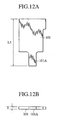
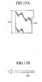
- the punch tip 99 comprises, referring to FIG. 12A together with FIG. 12B, FIG. 13A and FIG. 13B, an appropriate number of forming punch tips 101, each of which is provided with a press forming portion 101A in the leading end thereof and has a long size L5, and an appropriate number of clamping punch tips 103, each of which has a size L6 (L6 ⁇ L5) shorter than that of the forming punch tip 101.
- Both of the aforesaid tips 101 and 103 are attached to the aforesaid punch body 89 exchangeably.
- the aforesaid forming punch tips 101 are prepared preliminarily with various widths such as the width T1 for one piece, width 2T1 for two pieces and the width T3 for one piece.
- the aforesaid clamping punch tips 103 are prepared preliminarily with various widths such as the width T1 for two pieces, the width 1.5T1 for two pieces and the width 2T1 for one piece.
- the aforesaid die tool 85 is, as shown in FIG. 11, accommodated in a mounting hole 105H disposed in a lower die supporting member 105, and a die holder 109 is fixed on a die base 107 by means of a bolt 111.
- a die holder 109 On the die holder 109, an ejector plate 113 is mounted, and this ejector plate 113 is biased against the die holder 109 upward normally by means of a spring 115.
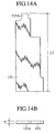
- the aforesaid die tip 121 comprises, as shown in FIG. 14A and FIG. 14B, an appropriate number of die tips 123, each of which is provided with a forming portion 123A in the leading end (upper end) thereof and has a size L7, and an appropriate number of sub die tips 125 each having a size L8 smaller than L7 (L8 ⁇ L7).
- a combination of both of the forming die tips 123 and the sub die tips 125 is attached to the aforesaid die holder 109 detachably and exchangeably.
- the aforesaid forming die tips 123 are prepared preliminarily with various widths T such as the width T1 for one piece, the width 2T1 for two pieces and the width T3 for one piece.
- the aforesaid sub die tips 125 are prepared preliminarily with various widths T such as the width T1 for two pieces, the width 1.5T1 for two piece and the width 2T1 for one piece.
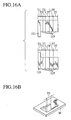
- an upward cut-and-raising and bending on a workpiece W by means of these sets an upward cut-and-raised and bet part shown in FIG. 16B can be obtained.
- two pieces of the forming punch tips 101 with the width 2T1, two pieces of the clamping punch tips 103 with the width T1 and one piece of the forming punch tip 101 with the width 2T1, and two pieces of the forming die tips 123 with the width 2T1, two pieces of the sub die tips 125 with the width T1 and one piece of the sub die tip 125 with the width 2T1 are combined together into two sets.
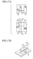
- an upward cut-and-raised and bent part shown in FIG. 17B can be obtained.
Landscapes
- Engineering & Computer Science (AREA)
- Mechanical Engineering (AREA)
- Mounting, Exchange, And Manufacturing Of Dies (AREA)
- Punching Or Piercing (AREA)
- Perforating, Stamping-Out Or Severing By Means Other Than Cutting (AREA)
Abstract
Description
- The present invention relates to a punch press tool that is used for forming a workpiece precisely, which is to be used for, for example, electronic parts, through a process consisting of upward or downward cut-and-raising and bending.
- Conventionally, in order to form a bent part through, for example, a downward or upward cut-and-raising and bending process being performed on a portion of a workpiece that is to be used for, for example, electronic parts, a punch tool or die tool is made corresponding to the width of the bent part, and such tools are exchanged to be used for different widths.
- However, using the individual tools discussed above causes a problem that it is necessary to make and prepare a large number of tools corresponding to various widths of respective bent parts. Moreover, there is another problem that the width of each of the bent parts cannot be designed freely.
- The present invention is intended to solve the problems described above, and an object of the invention is to provide a punch press tool that is capable of forming a bent part with a freely-designed width by downward or upward cut-and-raising and bending.
- In order to achieve the above object, a punch press tool according to a first aspect of the present invention comprises: a cylindrical punch guide; a punch body fitted slidably within the aforesaid punch guide; and a punch tip to perform press forming; wherein the aforesaid punch tip includes an appropriate number of long forming punch tips each including a press forming portion in the leading portion thereof and an appropriate number of clamping punch tip each having a shorter length compared with the forming punch tips; and both of the aforesaid tips are attached to the aforesaid punch body detachably and exchangeably.
- A punch press tool according to a second aspect of the present invention is a punch press tool of the first aspect in which at least either the aforesaid forming punch tips and the aforesaid clamping punch tips are split into a plurality.
- A punch press tool according to a third aspect of the present invention is a punch press tool according to the first or the second aspect in which provided is a stripper having a guide hole for receiving and guiding both of the aforesaid tips in the leading end side of the aforesaid punch guide and provided is a projected portion for clamping a workpiece in a position adjacent to the aforesaid guide hole located in the leading end of the aforesaid stripper.
- A punch press tool according to a fourth aspect of the present invention comprises: a die base; a die body supported on the aforesaid die base; and a die tip held in the aforesaid die body; wherein the aforesaid die tip comprises an appropriate number of forming die tips each including a forming portion in the leading end thereof and an appropriate number of sub die tips each having a smaller size compared with the forming die tips; and both of the aforesaid tips are attached to the aforesaid die body detachably and exchangeably.
- A punch press tool according to a fifth aspect of the present invention is a punch press tool according to the fourth aspect in which at least either the aforesaid forming die tips or the sub die tips are split into a plurality.
- A punch press tool according to a sixth aspect of the present invention comprises: a punch holder for the punch press; a sliding body supported slidably within the aforesaid punch holder; and a punch tip for performing press forming, which punch tip is attached to the leading end of the aforesaid sliding body; wherein the aforesaid punch tip includes an appropriate number of long forming punch tips each including a press forming portion in the leading end thereof and an appropriate number of clamping punch tips each having a shorter length compared with the forming punch tips; and the aforesaid forming punch tips and the aforesaid clamping punch tip are attached to the aforesaid sliding body detachably and exchangeably.
- A punch press tool according to a seventh aspect of the present invention is a punch press tool according to the sixth aspect in which at least either the aforesaid forming punch tips or the aforesaid clamping punch tips are split into a plurality.
- Thus, by means of combining appropriately the aforesaid forming punch tips, the aforesaid clamping punch tips, the aforesaid forming die tips and the aforesaid sub die tips, a downward or upward cut-and-raised and bent part can be formed in a portion of a workpiece.
- In addition, by means of selecting the width for each of the aforesaid tips, the width and the spacing of a bent part can be selected freely, and the punch tips and the die tips can be exchanged for forming various bent parts having various bent width.
- Furthermore, when forming into a downward cut-and-raised and bent part in a workpiece, the workpiece can be clamped between the projected portion provided in the leading end of the stripper and the clamping punch tip, so that a bent part can be obtained with high accuracy.
-
- FIG. 1 shows a cross-sectional front view of a punch press tool for executing the present invention.
- FIG. 2A shows a cross-sectional front view of a punch tip for downward forming.
- FIG. 2B shows a bottom view of a punch tip for downward forming.
- FIG. 3A shows a cross-sectional front view of a punch tip for downward clamping.
- FIG. 3B shows a bottom view of a punch tip for downward clamping.
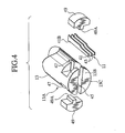
- FIG. 4 shows an exploded perspective view of a leading end of a punch body, which end receives punch tips disengageably.
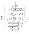
- FIG. 5 shows an exploded front view of a leading end of a punch body, which end receives punch tips disengageably.
- FIG. 6A shows a cross-sectional front view of a stripper.
- FIG. 6B shows a bottom view of a stripper.
- FIG. 7A shows a cross-sectional front view of a die tip for downward forming.
- FIG 7B shows a plan view of a die tip for downward forming.
- FIG. 8A shows a cross-sectional front view of a downward sub die tip.
- FIG. 8B shows a plan view of a downward sub die tip.
- FIG. 9A shows a side view of an example of combinations of a punch tip for downward forming with punch tips for downward clamping and of a die tip for downward forming with downward sub die tips.
- FIG. 9B shows a perspective view of an example of a workpiece provided with a downward bent part that is formed with the tools shown in the foregoing FIG 9A.
- FIG. 10A shows a side view of an example of combinations of punch tips for forming and a punch tip for clamping and of die tips for forming and sub die tips.
- FIG. 10B shows a perspective view of another example of a workpiece provided with downward bent parts that are formed with the tools shown in the foregoing FIG. 10A.
- FIG. 11 shows a cross-sectional front view of a punch press tool according to an embodiment other than the die shown in FIG. 1.
- FIG. 12A shows a cross-sectional front view of a punch tip for upward forming.
- FIG. 12B shows a bottom view of a punch tip for upward forming.
- FIG. 13A shows a cross-sectional front view of a punch tip for upward clamping.
- FIG. 13B shows a bottom view of a punch tip for upward clamping.
- FIG. 14A shows a cross-sectional front view of a die tip for upward forming.
- FIG. 14B shows a plan view of a die tip for upward forming.
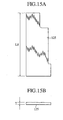
- FIG. 15A shows a cross-sectional front view of a downward sub die tip.
- FIG. 15B shows a plan view of a downward sub die tip.
- FIG. 16A shows a side view of an example of combinations of a punch tip for upward forming with punch tips for clamping and of a die tip for forming with sub die tips.
- FIG. 16B shows a perspective view of an example of a workpiece provided with an upward bent part that is formed with the tools shown in the foregoing FIG. 16A.
- FIG. 17A shows a side view of an example of combinations of punch tips for upward forming with punch tips for clamping and of die tips for forming with sub die tips.
- FIG. 17B shows a perspective view of another example of a workpiece provided with an upward bent part that is formed with the tools shown in the foregoing FIG. 17A.
-
- Hereunder, the best mode of carrying out the present invention will be described in detail referring to the attached drawings.
- FIG. 1 shows a
punch press tool 1 of high precision according to the present invention. Thispunch press tool 1 is constructed of apunch tool 3 and adie tool 5. In theaforesaid punch tool 3, apunch guide 9 is provided to be slidable upward and downward within ahole 7H formed in a upper die supporting member 7 that serves as a punch holder. Within thepunch guide 9, supported slidably upward and downward (upward and downward in FIG. 1) are apunch tip 11, apunch body 13 provided detachably on the upper side of thepunch tip 11 and apunch driver 17 connected integrally to thepunch body 13 by means of a threadedportion 15. - There is provided a
flange portion 19 on the upper end of theaforesaid punch guide 9. Thisflange portion 19 includes a lockinggroove 39 formed on a circumference surface thereof, and anO ring 21 as a locking member is inserted into the lockinggroove 39. Theaforesaid punch driver 17 consists of amiddle portion 23 with an outer diameter d and alower portion 25 with anouter diameter 25, in which the outer diameter d is adapted to be smaller than the outer diameter D. And aretainer collar 27 having an inner diameter smaller than the outer diameter D of thelower portion 25 is provided slidably upward and downward outside themiddle portion 23. Accordingly, theretainer collar 27 is slidable along only themiddle portion 23 of thepunch driver 17. Further, apunch head 29 is mounted on the upper end of thepunch driver 17. - Between the
retainer collar 27 and thepunch head 29, a resiliently stripping member such as astripper spring 31 is provided for constantly biasing theretainer collar 27 and punchhead 29 to press them apart. - Surrounding the peripheries of the
retainer collar 27 and thestripper spring 31, aslide collar 33 that servers as a fixing member is disposed slidably. On the internal surface of the lower end of theslide collar 33, a lockingprojection 37 is formed. This lockingprojection 37 serves to press downward a clampingprojection 35 formed in the lower end of theretainer collar 27 so as to allow the lower end of theslide collar 33 to engage lockably the O-ring 21 disposed in theflange portion 19 of thepunch guide 9. Between theflange portion 19 of theaforesaid punch guide 9 and the upper surface of the upper die supporting member 7, alifter spring 20 is disposed for biasing upward thepunch guide 9 constantly. - Referring to FIG. 2A together with FIG. 2B, FIG. 3A and FIG. 3B, the
aforesaid punch tip 11 comprises an appropriate number of formingpunch tips 41 each of which includes a press forming portion in the leading end portion thereof and has a length L1 and an appropriate number of clampingpunch tips 43 each of which has a shorter length L2 compared with that of the forming punch tip 41 (L2<L1). Bothtips aforesaid punch body 13 detachably. - FIG. 2A and FIG. 2B show the forming
punch tip 41. Referring to FIG 2A, thehead portion 41B hasprojections 41D in the bottom thereof, which projections project toward right and left with respect to thebody portion 41C so as to make a step in the vertical direction. FIG. 3A and FIG. 3B show the aforesaidclamping punch tip 43. Referring to FIG. 3A, in the similar manner to the forming punch tip, thehead portion 43B hasprojections 43D in the bottom thereof, which projections project toward right and left with respect to thebody portion 43C so as to make a step in the vertical direction. - The aforesaid forming
punch tips 41 are prepared preliminarily with various widths T such as the width T1 for one piece and the width 2T1 for two pieces. Also, the aforesaidclamping punch tips 43 are prepared preliminarily with various widths T such as the width T1 for two pieces, the width 1.5T1 for two pieces and the width 2T1 for one piece. - Referring also to FIG. 4 and FIG. 5, in the
leading end portion 13A of theaforesaid punch body 13, apunch receiving recess 45 including anopening 13C is formed in theleading end surface 13B. Further, in theleading end portion 13A of thepunch body 13, locking recesses 47 includingopenings 47A formed on the periphery surfaces thereof and communicating with the aforesaidpunch receiving recess 45 are formed. A lockingpiece 49 is provided with anengaging surface 49A in an inner side thereof, which is adapted to be engageable with a peripheral surface of thepunch tip 11 attached inside the aforesaidpunch receiving recess 45. The lockingpiece 49 is disposed detachably in one of the aforesaid locking recesses 47, and the paired locking piece is disposed in the other locking recess located oppositely to the foregoing locking recess. Theengaging surface 49A of theaforesaid locking piece 49 is formed with the shape corresponding to a shape of the outer periphery of thepunch tip 11. - The forming
punch tip 41 and the clampingpunch tip 43, both of which compose theaforesaid punch tip 11, are provided with theprojections respective head portions aforesaid locking recess 47 and are engageable with theengaging surface 49A of theaforesaid locking piece 49. Moreover, theaforesaid punch body 13 is provided with a key 53 in the peripheral surface thereof, and this key 53 is received in akey groove 9A that is formed on thepunch guide 9. - At the leading end (lower end) of the
aforesaid punch guide 9, across-shaped plate 55 is fitted, and inside this plate 55 across-shaped plate 57 is fixed by means of a bolt or the like. Referring also to FIG. 6A and FIG. 6B, at the center of this plate 57 astripper 59 is disposed, which stripper is formed with aguide hole 59H for receiving and guiding theaforesaid punch tip 11 composed of the formingpunch tips 41 and the clampingpunch tips 43. On the leading end of thisstripper 59, a projectedportion 59T is disposed adjacent to theaforesaid guide hole 59H, which projected portion serves for clamping the work sheet. - The
aforesaid die tool 5 is, as shown in FIG. 1, mounted within a mountinghole 61H disposed in the lowerdie supporting member 61, and adie body 67 is supported on adie base 63 via adie holder 65 and fastened by means of abolt 69. Withinrespective holes aforesaid die holder 65 and thedie body 67 respectively, adie tip 75 is held detachably. Theaforesaid die tip 75 comprises an appropriate number of the forming dietips 77, which have a size L3, having a formingportion 77A as shown in FIG. 7A and FIG. 7B as well as an appropriate number of the sub dietips 79, which have a size L4 smaller than L3 (L4<L3), as shown in FIG. 8A and FIG. 8B. Such tips, i.e., the forming dietips 77 and the sub dietips 79 are disposed detachably and exchangeably in theaforesaid die body 67. - The aforesaid forming die
tips 77 are prepared preliminarily with various widths T such as width T1 for one piece and width 2T1 for two pieces. Also, the aforesaid sub dietips 79 are prepared preliminarily with various widths such as width T1 for two pieces, width 1.5T1 for two pieces and width 2T1 for one piece. - According to the construction described above, as shown in FIG. 5, the appropriate number of forming
punch tips 41 and the appropriate number of clampingpunch tips 43 are bound together to form thepunch tip 11. Such bound tips are inserted from the right in the figure into an opening formed in the leading end surface of thepunch receiving recess 45 that is disposed in theleading end portion 13A of thepunch body 13. And, when a pair of the lockingpieces 49 are mounted within the lockingrecess 47, which is formed in such a manner that theopenings 47A formed on the peripheral surface of theleading end portion 13A of theaforesaid punch body 13 communicate with the aforesaidpunch receiving recess 45, the engagingsurface 49 formed in the inner side of the lockingpiece 49 comes to engage the peripheral surface of thepunch tip 11. Thepunch body 13 including thepunch tip 11 is accommodated in the hole 9H formed in thepunch guide 9, which is shown in Fig. 1. - As shown in FIG. 1, when the top of the
punch head 29 is struck by means of a striker that is not shown, thepunch guide 9 moves downward against the bias of thelifter spring 20. While thepunch guide 9 moves downward further, the lower surface of the projectedportion 59T of thestripper 59 and the upper surface of the formingdie tip 77 hold the workpiece cooperatively, and the formingdie tip 77 performs to cut-and-raise and to bend downward for forming a bent part. - By way of example, as shown in FIG. 9A, one piece of the forming
punch tip 41 with the width T1, two pieces of the clampingpunch tips 43 with the width T1 and one piece of the clampingpunch tip 43 with the width T2, and one piece of the formingdie tip 77 with the width T1, two pieces of the sub dietips 79 with the width T1, two pieces of the sub dietips 79 with the width 1.5T1 and two pieces of the sub dietips 79 with the width 2T1 are combined together into two sets. And when such combinations are used for bending a workpiece downward, a downward cut-and-raised and bent part can be obtained as shown in FIG. 9B. - Alternatively, as shown in FIG. 10A by way of example, one piece of the forming
punch tip 41 with the width T1, one piece of the formingpunch tip 41 with the width 2T1 and one piece of the clampingpunch tip 43 with the width 21T, and one piece of the formingdie tip 77 with the width T1, one piece of the formingdie tip 77 with the width 2T1, two pieces of the sub dietips 79 with the width T1, two pieces of the sub dietips 79 with the width 1.5T1 and one piece of the sub dietip 79 with the width 2T1 are combined together into two sets. And when such combinations are used for bending a workpiece downward, a downward cut-and-raised and bent part can be obtained as shown in FIG. 10B. - Furthermore, by making use of the forming
punch tip 41, the clampingpunch tip 43, the formingdie tip 77 and the sub dietip 79, and by making various combinations through varying the width and the number of these tips, various bent parts that have bent widths other than discussed above and appropriate spacing can be obtained. - FIG. 11 shows a
punch tool 81, which is an alternative to the same shown in FIG. 1, for a high precision punch press according to another embodiment of the present invention. In FIG. 11, it is shown that thepunch tool 81 of a punch press comprises apunch tool 83 and adie tool 85. In theaforesaid punch tool 83, there is included an upperdie supporting member 87 as a punch holder, which member is provided with ahole 87H. Apunch body 89 as a sliding body is accommodated in this hole slidably upward and downward. On the top of thepunch body 89, a punch head is mounted. Between a lower surface of thepunch head 91 and an upper surface of the aforesaid upperdie supporting member 87, there is interposed alifter spring 93 that biases thepunch body 89 upward normally. - In the leading end (lower end) of the
aforesaid punch body 89, across-shaped plate 95 is fitted, and anothercross-shaped plate 97 is fixed to the forgoingplate 95 by means of a bolt or the like. Furthermore, apunch tip 99 is inserted into the center portion of theaforesaid plate 95. - The
punch tip 99 comprises, referring to FIG. 12A together with FIG. 12B, FIG. 13A and FIG. 13B, an appropriate number of formingpunch tips 101, each of which is provided with apress forming portion 101A in the leading end thereof and has a long size L5, and an appropriate number of clampingpunch tips 103, each of which has a size L6 (L6<L5) shorter than that of the formingpunch tip 101. Both of theaforesaid tips aforesaid punch body 89 exchangeably. - The aforesaid forming
punch tips 101 are prepared preliminarily with various widths such as the width T1 for one piece, width 2T1 for two pieces and the width T3 for one piece. Also, the aforesaidclamping punch tips 103 are prepared preliminarily with various widths such as the width T1 for two pieces, the width 1.5T1 for two pieces and the width 2T1 for one piece. - The
aforesaid die tool 85 is, as shown in FIG. 11, accommodated in a mountinghole 105H disposed in a lowerdie supporting member 105, and adie holder 109 is fixed on adie base 107 by means of abolt 111. On thedie holder 109, anejector plate 113 is mounted, and thisejector plate 113 is biased against thedie holder 109 upward normally by means of aspring 115. - Within
holes aforesaid die holder 109 and theejector plate 113, thedie tip 121 is held detachably. Theaforesaid die tip 121 comprises, as shown in FIG. 14A and FIG. 14B, an appropriate number ofdie tips 123, each of which is provided with a formingportion 123A in the leading end (upper end) thereof and has a size L7, and an appropriate number of sub dietips 125 each having a size L8 smaller than L7 (L8<L7). A combination of both of the forming dietips 123 and the sub dietips 125 is attached to theaforesaid die holder 109 detachably and exchangeably. - The aforesaid forming die
tips 123 are prepared preliminarily with various widths T such as the width T1 for one piece, the width 2T1 for two pieces and the width T3 for one piece. Also, the aforesaid sub dietips 125 are prepared preliminarily with various widths T such as the width T1 for two pieces, the width 1.5T1 for two piece and the width 2T1 for one piece. - According to the construction described above, as shown in FIG. 11, when the leading end of the
punch head 91 is struck with a striker that is not shown, thepunch body 89 moves downward against the biasing force from thelifter spring 93. While thepunch body 89 moves downward further, the lower surface of the formingpunch 101 presses the upper surface of theaforesaid ejector plate 113 against the biasing force from thespring 115 and the upper surface of the formingdie tip 123 presses upward the workpiece, so that an upward cut-and-raised part can be obtained. - By way of example, as shown in FIG. 16A, one piece of the forming
punch tip 101 with the width T1, two pieces of the clampingpunch tips 103 with the width T1, two pieces of the clampingpunch tips 103 with the width 1.5T1 and one piece of the clampingpunch tip 103 with the width T2, and one piece of the formingdie tip 123 with the width T1, two pieces of the sub dietips 125 with the width T1, two pieces of the sub dietips 125 with the width 1.5T1 and one piece of thesub die tip 125 with the width 2T1 are combined together into two sets. When performing an upward cut-and-raising and bending on a workpiece W by means of these sets, an upward cut-and-raised and bet part shown in FIG. 16B can be obtained. - Alternatively, as shown in FIG. 17A, two pieces of the forming
punch tips 101 with the width 2T1, two pieces of the clampingpunch tips 103 with the width T1 and one piece of the formingpunch tip 101 with the width 2T1, and two pieces of the forming dietips 123 with the width 2T1, two pieces of the sub dietips 125 with the width T1 and one piece of thesub die tip 125 with the width 2T1 are combined together into two sets. When performing an upward cut-and-raising and bending on a workpiece W by means of these sets, an upward cut-and-raised and bent part shown in FIG. 17B can be obtained. - Furthermore, by making use of the forming
punch tips 101, the clampingpunch tips 103, the forming dietips 123 and the sub dietips 125 and by making various combinations through varying the width and the number of these tips, various bent parts which have bent widths other than discussed above and appropriate spacing can be obtained. - It should be noted that all of the substances of the Japan Patent Application No. 2002-172740 filed on June 13th of 2002 be incorporated in this specification by a reference.
- Furthermore, the present invention should not be limited by the embodiment of the present invention described above, and other embodiments may be executed by providing appropriate changes to the present invention.
Claims (7)
- A punch press tool comprising:wherein said punch tip comprises an appropriate number of forming punch tips each including a press forming portion in a leading end thereof and an appropriate number of clamping punch tips each having shorter length compared with said forming punch tips; anda cylindrical punch guide;a punch body fit slidably into said punch guide; anda punch tip for performing the press forming,
both of said tips are attached to said punch body detachably and exchangeably. - The punch press tool according to claim 1, wherein at least either said forming punch tips or said clamping punch tips are split into a plurality.
- The punch press tool according to claim 2, wherein said punch guide is provided with a stripper in the leading end thereof, said stripper including a guide hole for receiving and guiding both of said tips; and
said stripper is provided with a projected portion for clamping a workpiece in a position adjacent to said guide hole located in the leading end of said stripper. - A punch press tool comprising:wherein said die tip comprises an appropriate number of forming die tips each including a forming portion in a leading end thereof and an appropriate number of sub die tips each having a smaller size compared with said forming die tips; anda die base;a die body supported on said die base; anda die tip held in said die body;
both of said tips are attached to said die body detachably and exchangeably. - The punch press tool according to claim 4, wherein at least either said forming die tips or said sub die tips are split into a plurality.
- A punch press tool comprising:wherein said punch tip comprises an appropriate number of long forming punch tips each including a press forming portion in a leading end thereof and an appropriate number of clamping punch tips each having a shorter length compared with said forming punch tips; anda punch holder for punch press;a sliding body supported slidably within said punch holder; anda punch tip for performing press forming, said punch tip provided in a leading end of said sliding body;
said forming punch tips and said clamping punch tips are attached to said sliding body detachably and exchangeably. - The punch press tool according to claim 6, wherein at least either said forming punch tips or said clamping punch tips arez split into a plurality.
Applications Claiming Priority (3)
| Application Number | Priority Date | Filing Date | Title |
|---|---|---|---|
| JP2002172740 | 2002-06-13 | ||
| JP2002172740A JP4133005B2 (en) | 2002-06-13 | 2002-06-13 | Die for punch press |
| PCT/JP2003/007504 WO2003106067A1 (en) | 2002-06-13 | 2003-06-12 | Punch press die |
Publications (3)
| Publication Number | Publication Date |
|---|---|
| EP1529576A1 true EP1529576A1 (en) | 2005-05-11 |
| EP1529576A4 EP1529576A4 (en) | 2007-04-04 |
| EP1529576B1 EP1529576B1 (en) | 2008-04-09 |
Family
ID=29727878
Family Applications (1)
| Application Number | Title | Priority Date | Filing Date |
|---|---|---|---|
| EP03733389A Expired - Lifetime EP1529576B1 (en) | 2002-06-13 | 2003-06-12 | Punch press die |
Country Status (6)
| Country | Link |
|---|---|
| US (1) | US7225659B2 (en) |
| EP (1) | EP1529576B1 (en) |
| JP (1) | JP4133005B2 (en) |
| DE (1) | DE60320261T2 (en) |
| TW (1) | TWI222905B (en) |
| WO (1) | WO2003106067A1 (en) |
Cited By (1)
| Publication number | Priority date | Publication date | Assignee | Title |
|---|---|---|---|---|
| EP3150297A1 (en) * | 2015-09-30 | 2017-04-05 | TKR Spezialwerkzeuge GmbH | Hydraulic punching device and punch support for punching device |
Families Citing this family (10)
| Publication number | Priority date | Publication date | Assignee | Title |
|---|---|---|---|---|
| US7610838B2 (en) * | 2007-03-30 | 2009-11-03 | Staples The Office Superstore, Llc | Hole punch |
| TWI409656B (en) * | 2007-12-31 | 2013-09-21 | Hon Hai Prec Ind Co Ltd | System and method for outspreading an irregular curve of a part of a punching die |
| CN101569908B (en) | 2008-04-28 | 2013-11-06 | 鸿富锦精密工业(深圳)有限公司 | Stamping die |
| DE102010006939A1 (en) | 2010-02-04 | 2011-08-04 | Voxeljet Technology GmbH, 86167 | Device for producing three-dimensional models |
| USD669936S1 (en) | 2011-05-25 | 2012-10-30 | Staples The Office Superstore, Llc | Hole punch |
| USD736280S1 (en) * | 2012-04-11 | 2015-08-11 | Milwaukee Electric Tool Corporation | Die |
| CN102632129A (en) * | 2012-04-16 | 2012-08-15 | 江苏金方圆数控机床有限公司 | Contactless cutting mould for numerical control turret punch press |
| CN107186047A (en) * | 2017-06-05 | 2017-09-22 | 湖南七纬科技有限公司 | A kind of aluminium alloy extrusions processing blanking die |
| CN110280646B (en) * | 2019-07-23 | 2023-12-22 | 西安工业大学 | Cold stamping die |
| CN114951864B (en) * | 2022-07-13 | 2022-11-25 | 杭州爱新凯科技有限公司 | Punching needle processing method of micro-punching machine and micro-punching machine |
Family Cites Families (20)
| Publication number | Priority date | Publication date | Assignee | Title |
|---|---|---|---|---|
| US1402284A (en) * | 1918-05-29 | 1922-01-03 | George H Daniels | Sectional die |
| US1449385A (en) * | 1919-05-20 | 1923-03-27 | Ludwig M Dieterich | Art and apparatus for forcing material into a predetermined form |
| US1468271A (en) * | 1921-04-18 | 1923-09-18 | American Multigraph Co | Mechanism for making printing-strip holders |
| US1939503A (en) * | 1929-02-11 | 1933-12-12 | Guardian Trust Company Of Detr | Tool holder |
| US2017247A (en) * | 1934-10-17 | 1935-10-15 | George A Vis | Tool attachment |
| US3100411A (en) * | 1959-04-22 | 1963-08-13 | Carrick Prec Tools Ltd | Press tools |
| US3077135A (en) * | 1960-02-29 | 1963-02-12 | Henn Harry Walther | Close center slot perforating device |
| US3690209A (en) * | 1969-09-25 | 1972-09-12 | Robert J Gargrave | Die-assembly |
| JPS6277124A (en) | 1985-09-30 | 1987-04-09 | Ohashi Seisakusho:Kk | Press metal die for punching and burring |
| JP2647405B2 (en) | 1988-01-22 | 1997-08-27 | 株式会社協豊製作所 | Press working method with drilling, apparatus therefor and punch for the working method |
| JP2837719B2 (en) * | 1989-12-18 | 1998-12-16 | 株式会社アマダメトレックス | Mold for punch press |
| JP2627354B2 (en) | 1990-07-23 | 1997-07-02 | 三洋電機株式会社 | Magnetic sensors and magnetic rotary encoders |
| JP2548763Y2 (en) * | 1990-11-28 | 1997-09-24 | 株式会社アマダ | Turret punch press |
| JP2578289B2 (en) | 1992-04-08 | 1997-02-05 | 株式会社アマダメトレックス | Louver mold |
| JP2545176B2 (en) | 1992-05-19 | 1996-10-16 | 株式会社アマダメトレックス | Mold for punching machine |
| JP2611089B2 (en) | 1992-06-30 | 1997-05-21 | 株式会社アマダメトレックス | Mold for molding |
| US5661993A (en) | 1995-05-22 | 1997-09-02 | Tee-Lok Corporation | Punch tool and method for manufacturing truss plates |
| WO1999011399A1 (en) | 1997-09-04 | 1999-03-11 | Amada Metorecs Company, Limited | Mold for forming projection |
| JP3722258B2 (en) * | 1998-09-25 | 2005-11-30 | 日本碍子株式会社 | Punching device for punching, punch for punching, and method for manufacturing punch for punching |
| JP2001062784A (en) * | 1999-08-27 | 2001-03-13 | Ngk Insulators Ltd | Method for punching fragile material and punching die used for the same |
-
2002
- 2002-06-13 JP JP2002172740A patent/JP4133005B2/en not_active Expired - Fee Related
-
2003
- 2003-06-12 EP EP03733389A patent/EP1529576B1/en not_active Expired - Lifetime
- 2003-06-12 TW TW92115937A patent/TWI222905B/en not_active IP Right Cessation
- 2003-06-12 DE DE2003620261 patent/DE60320261T2/en not_active Expired - Lifetime
- 2003-06-12 WO PCT/JP2003/007504 patent/WO2003106067A1/en active IP Right Grant
- 2003-06-12 US US10/516,316 patent/US7225659B2/en not_active Expired - Fee Related
Non-Patent Citations (2)
| Title |
|---|
| No further relevant documents disclosed * |
| See also references of WO03106067A1 * |
Cited By (2)
| Publication number | Priority date | Publication date | Assignee | Title |
|---|---|---|---|---|
| EP3150297A1 (en) * | 2015-09-30 | 2017-04-05 | TKR Spezialwerkzeuge GmbH | Hydraulic punching device and punch support for punching device |
| US10052780B2 (en) | 2015-09-30 | 2018-08-21 | Tkr Spezialwerkzeuge Gmbh | Hydraulic punch machine, and punch carrier for a punch machine |
Also Published As
| Publication number | Publication date |
|---|---|
| DE60320261D1 (en) | 2008-05-21 |
| TWI222905B (en) | 2004-11-01 |
| JP2004017062A (en) | 2004-01-22 |
| US7225659B2 (en) | 2007-06-05 |
| EP1529576B1 (en) | 2008-04-09 |
| WO2003106067A1 (en) | 2003-12-24 |
| US20050217343A1 (en) | 2005-10-06 |
| TW200405830A (en) | 2004-04-16 |
| EP1529576A4 (en) | 2007-04-04 |
| JP4133005B2 (en) | 2008-08-13 |
| DE60320261T2 (en) | 2009-05-20 |
Similar Documents
| Publication | Publication Date | Title |
|---|---|---|
| EP1529576B1 (en) | Punch press die | |
| CN107186058B (en) | Stamping tool, drift termination and the method that drift termination and punch body is fixed | |
| US7490501B2 (en) | Method of processing formed product, and metal cope and metal drag used for the method | |
| CN213350457U (en) | Keyboard bottom plate stamping die of high accuracy location | |
| JP2002219529A (en) | Press die | |
| US9409223B2 (en) | Punch assemblies and universal punch therefor | |
| JP2014233749A (en) | Drilling device | |
| EP0972584A2 (en) | Forming tools | |
| GB1563737A (en) | Stock lifter device for metal-working presses | |
| US20140318343A1 (en) | Punching Machine | |
| CN210701996U (en) | Stamping die and stamping equipment | |
| US4945752A (en) | Tool carrier for a punch or stamping machine | |
| CN108297597B (en) | Stamping steel seal tool | |
| US9755687B2 (en) | Housing mounting mechanism for portable electronic device | |
| CN217343142U (en) | Workpiece shaping device | |
| CN213258917U (en) | Universal grinding jig for round punch | |
| JP6575297B2 (en) | Punch mold | |
| CN213162904U (en) | Calendering part manufacturing installation | |
| JP3662686B2 (en) | Stamping device | |
| JP6717416B2 (en) | Punch mold | |
| CN219233705U (en) | Fine blanking wedge mechanism | |
| CN110191787B (en) | Insertion device for inserting first punches or second punches in an alternating manner | |
| CN213856661U (en) | Hardware composite stamping die | |
| KR100634618B1 (en) | Identification number punch guiding device of vehicle | |
| JP2534068Y2 (en) | Different direction drilling structure |
Legal Events
| Date | Code | Title | Description |
|---|---|---|---|
| PUAI | Public reference made under article 153(3) epc to a published international application that has entered the european phase |
Free format text: ORIGINAL CODE: 0009012 |
|
| 17P | Request for examination filed |
Effective date: 20041117 |
|
| AK | Designated contracting states |
Kind code of ref document: A1 Designated state(s): AT BE BG CH CY CZ DE DK EE ES FI FR GB GR HU IE IT LI LU MC NL PT RO SE SI SK TR |
|
| RBV | Designated contracting states (corrected) |
Designated state(s): DE |
|
| A4 | Supplementary search report drawn up and despatched |
Effective date: 20070307 |
|
| GRAP | Despatch of communication of intention to grant a patent |
Free format text: ORIGINAL CODE: EPIDOSNIGR1 |
|
| GRAS | Grant fee paid |
Free format text: ORIGINAL CODE: EPIDOSNIGR3 |
|
| GRAA | (expected) grant |
Free format text: ORIGINAL CODE: 0009210 |
|
| AK | Designated contracting states |
Kind code of ref document: B1 Designated state(s): DE |
|
| REF | Corresponds to: |
Ref document number: 60320261 Country of ref document: DE Date of ref document: 20080521 Kind code of ref document: P |
|
| PLBE | No opposition filed within time limit |
Free format text: ORIGINAL CODE: 0009261 |
|
| STAA | Information on the status of an ep patent application or granted ep patent |
Free format text: STATUS: NO OPPOSITION FILED WITHIN TIME LIMIT |
|
| 26N | No opposition filed |
Effective date: 20090112 |
|
| PGFP | Annual fee paid to national office [announced via postgrant information from national office to epo] |
Ref country code: DE Payment date: 20120627 Year of fee payment: 10 |
|
| REG | Reference to a national code |
Ref country code: DE Ref legal event code: R119 Ref document number: 60320261 Country of ref document: DE Effective date: 20140101 |
|
| PG25 | Lapsed in a contracting state [announced via postgrant information from national office to epo] |
Ref country code: DE Free format text: LAPSE BECAUSE OF NON-PAYMENT OF DUE FEES Effective date: 20140101 |