JP4114824B2 - Image generating apparatus and information storage medium - Google Patents
Image generating apparatus and information storage medium Download PDFInfo
- Publication number
- JP4114824B2 JP4114824B2 JP13138698A JP13138698A JP4114824B2 JP 4114824 B2 JP4114824 B2 JP 4114824B2 JP 13138698 A JP13138698 A JP 13138698A JP 13138698 A JP13138698 A JP 13138698A JP 4114824 B2 JP4114824 B2 JP 4114824B2
- Authority
- JP
- Japan
- Prior art keywords
- image
- space
- given
- changing
- area
- Prior art date
- Legal status (The legal status is an assumption and is not a legal conclusion. Google has not performed a legal analysis and makes no representation as to the accuracy of the status listed.)
- Expired - Lifetime
Links
Images


Classifications
-
- A—HUMAN NECESSITIES
- A63—SPORTS; GAMES; AMUSEMENTS
- A63F—CARD, BOARD, OR ROULETTE GAMES; INDOOR GAMES USING SMALL MOVING PLAYING BODIES; VIDEO GAMES; GAMES NOT OTHERWISE PROVIDED FOR
- A63F2300/00—Features of games using an electronically generated display having two or more dimensions, e.g. on a television screen, showing representations related to the game
- A63F2300/60—Methods for processing data by generating or executing the game program
- A63F2300/66—Methods for processing data by generating or executing the game program for rendering three dimensional images
Description
【0001】
【発明の属する技術分野】
本発明は、オブジェクト空間内の所与の視点での画像を生成する画像生成装置及び情報記憶媒体に関する。
【0002】
【背景技術及び発明が解決しようとする課題】
従来より、仮想的な3次元空間であるオブジェクト空間内に複数のオブジェクトを配置し、オブジェクト空間内の所与の視点から見える画像を生成する画像生成装置が開発、実用化されており、いわゆる仮想現実を体験できるものとして人気が高い。対戦ゲームを楽しむことができる画像生成装置を例にとれば、プレーヤは、自身が操作するキャラクタ(人間、ロボットなど)をオブジェクト空間内で移動させ、他のプレーヤやコンピュータが操作するキャラクタと対戦することで3次元ゲームを楽しむ。
【0003】
さて、このような画像生成装置では、図13(A)に示すように、キャラクタ400と視点410との間に障害物となるオブジェクト420が入り込むと、図13(B)に示すようにプレーヤの視界がオブジェクト420によりふさがれてしまい、キャラクタ400やその周辺がプレーヤから見えなくなってしまうという問題がある。
【0004】
このような問題を解決する従来技術として、例えば特開平9−50541号公報に開示される技術が知られている。この従来技術では、視点とキャラクタの間に障害物となるオブジェクトが入り込んだか否かを判定して、入り込んだと判定した場合にはオブジェクトを透過表示にすることで、上記問題を解決している。
【0005】
しかしながら、この従来技術では、視点の位置、キャラクタの位置、障害物となるオブジェクトの位置という3つの位置に基づき、オブジェクトが入り込んだか否かの判定を行わなければならない。したがって、処理負担及び処理時間が過大になるという問題があった。
【0006】
また、この従来技術には、視点障害物を透過表示にする以外に、他の応用例がないという問題点もある。
【0007】
本発明は、以上のような技術的課題に鑑みてなされたものであり、その目的とするところは、2つのオブジェクト間の位置関係を調べるだけで様々な画像表現が可能になる画像生成装置及び情報記憶媒体を提供することにある。
【0008】
また本発明の他の目的は、他のオブジェクトが視点障害物となって注視すべきオブジェクトが見えなくなるという事態を防止できる画像生成装置及び情報記憶媒体を提供することにある。
【0009】
【課題を解決するための手段】
上記課題を解決するために、本発明は、オブジェクト空間内の所与の視点での画像を生成する画像生成装置であって、第1、第2のオブジェクトを含む複数のオブジェクトが配置されるオブジェクト空間を形成する手段と、前記第1のオブジェクトと前記第2のオブジェクトとの位置関係に基づいて前記第2のオブジェクトの画像を変更する手段と、オブジェクト空間内の所与の視点での画像を生成する手段とを含むことを特徴とする。
【0010】
本発明によれば、例えば移動体、マップ、背景などのオブジェクトが配置されるオブジェクト空間が形成される。そして、これらのオブジェクトの中の第1、第2のオブジェクトの位置関係がどのようになっているかが判断され、その位置関係に基づいて第2のオブジェクトの画像が変更される。例えば第1のオブジェクトがキャラクタで第2のオブジェクトが障害物である場合には、キャラクタと障害物との位置関係に応じて障害物が透過表示、半透明表示、メッシュ表示されたり、障害物の形状、色、輝度、テクスチャなどが変更される。このようにすることで、例えば障害物が邪魔になって障害物の向こう側のキャラクタが視点から見えなくなる問題を解消したり、障害物の向こう側が見えるようにしてゲームプレイを容易にしたりすることが可能になる。特に本発明によれば、視点の位置を考慮しなくても、第1、第2のオブジェクトの位置関係のみによって第2のオブジェクトの画像を変更できるため、処理負担、処理時間を従来技術に比べて格段に軽減できるようになる。
【0011】
また本発明は、前記第1のオブジェクトの位置により特定される所与のエリアに前記第2のオブジェクトが入った場合に、前記第2のオブジェクトの画像を変更することを特徴とする。ここで第1のオブジェクトの位置としては第1のオブジェクトの例えば代表点を考えることができる。所与のエリアは、この第1のオブジェクトの位置により、その設けられる場所などが特定される。所与のエリアが例えば円や扇形である場合には、第1のオブジェクトの位置、あるいはその位置から所与の距離だけ離れた位置を円や扇形の中心とすることができる。また、第1のオブジェクトが移動体である場合には、その移動に追従させて所与のエリアを移動させることもできる。そして、本発明によれば、このような所与のエリアに第2のオブジェクトが入り込むと第2のオブジェクトの画像が変更される。即ち、第2のオブジェクトの画像が変更されるエリアを、第1のオブジェクトに付随させて設けることができるようになる。
【0012】
また本発明は、前記所与のエリアが、前記第1のオブジェクトと前記第1のオブジェクトに追従する視点との間に設けられていることを特徴とする。本発明によれば、第1のオブジェクトの移動に視点が追従する。そして、第1のオブジェクトとこれに追従する視点との間に上記所与のエリアが介在するように、該所与のエリアの位置が予め決められている。そして、この所与のエリアに第2のオブジェクトが入り込むと、第2のオブジェクトの画像が変更される。この場合、画像を変更するか否かは、視点の位置については考慮することなく、第1、第2のオブジェクトの位置関係によって判断される。したがって、本発明によれば、第1、第2のオブジェクトの位置関係を判断するだけで、視点の位置については判断することなく、第1のオブジェクトと視点との間に入り込んだ第2のオブジェクトを透過表示、半透明表示、或いはメッシュ表示にすることが可能になる。したがって、第1、第2のオブジェクトのみならず視点の位置関係も判断する従来技術に比べて、格段に少ない処理負担、処理時間で視点障害物の問題を解消できるようになる。
【0013】
また本発明は、前記所与のエリアが、前記第1のオブジェクトの位置により中心が特定される扇形であることを特徴とする。このようにすれば、第2のオブジェクトが所与のエリアに入り込んだか否かの判断を、簡易で負担が少ない処理で実現できるようになる。
【0014】
また本発明は、前記第2のオブジェクトの位置により特定される所与のエリアに前記第1のオブジェクトが入った場合に、前記第2のオブジェクトの画像を変更することを特徴とする。ここで第2のオブジェクトの位置としては第2のオブジェクトの例えば代表点を考えることができる。所与のエリアは、この第2のオブジェクトの位置により、その設けられる場所などが特定される。例えば所与のエリアが円や扇形である場合には、第2のオブジェクトの位置、あるいはその位置から所与の距離だけ離れた位置を円や扇形の中心とすることができる。そして、本発明によれば、このような所与のエリアに第1のオブジェクトが入り込むと第2のオブジェクトの画像が変更される。即ち、第2のオブジェクトの画像が変更されるエリアを、第2のオブジェクト自体に付随させて設けることができるようになる。
【0015】
また本発明は、前記所与のエリアが、前記第2のオブジェクトの位置により中心が特定される扇形であることを特徴とする。このようにすれば、第1のオブジェクトが所与のエリアに入り込んだか否かの判断を、簡易で負担が少ない処理で実現できるようになる。
【0016】
また本発明は、前記中心が前記第2のオブジェクトの外側にあると共に、扇形の前記所与のエリアが前記第2のオブジェクトに重なるように配置されていることを特徴とする。このようにすれば、所与のエリアの中の第2のオブジェクトの向こう側(扇形の中心がある側)の部分に第1のオブジェクトが入り込んだ場合にも、第2のオブジェクトの手前側(扇形の弧がある側)の部分に第1のオブジェクトが入り込んだ場合にも、第2のオブジェクトの画像を変更できるようになる。
【0017】
また本発明は、前記第2のオブジェクトの位置と前記中心との距離、前記扇形の半径、及び前記扇形の中心角の少なくとも1つを、前記第2のオブジェクトの種類に応じて変えることを特徴とする。このようにすれば、第2のオブジェクトの種類(大きさ、形状)に応じて、適切な扇形のエリアを第2のオブジェクト毎に設定できるようになる。
【0018】
なお、本発明では、前記第1のオブジェクトが、前記オブジェクト空間内において移動する移動体であり、前記第2のオブジェクトが、前記オブジェクト空間内においてその位置が固定される固定物であることが望ましい。
【0019】
また、前記第2のオブジェクトの画像を変更する処理としては、前記第2のオブジェクトを透過表示にする処理、前記第2のオブジェクトを半透明表示にする処理、前記第2のオブジェクトをメッシュ表示にする処理、前記第2のオブジェクトを他のオブジェクトに切り替える処理、前記第2のオブジェクトの形状を変更する処理、前記第2のオブジェクトの色を変更する処理、前記第2のオブジェクトの輝度を変更する処理、及び前記第2のオブジェクトのテクスチャを変更する処理などを考えることができる。
【0020】
【発明の実施の形態】
以下、本発明の好適な実施形態について図面を用いて説明する。なお以下では、本発明を、複数のキャラクタが敵と味方に分かれて対戦するゲームに適用した場合を例にとり説明するが、本発明はこれに限定されず種々のゲームに適用できる。
【0021】
図1に、本実施形態の画像生成装置の機能ブロック図の一例を示す。
【0022】
ここで操作部10は、プレーヤが、レバーやボタンなどを操作することで操作データを入力するためのものであり、操作部10にて得られた操作データは処理部100に入力される。
【0023】
処理部100は、上記操作データと所与のプログラムなどに基づいて、オブジェクト空間にオブジェクトを配置する処理や、このオブジェクト空間の所与の視点での画像を生成する処理を行うものである。この処理部100の機能は、CPU(CISC型、RISC型)、DSP、ASIC(ゲートアレイ等)、メモリなどのハードウェアにより実現できる。
【0024】
情報記憶媒体190は、プログラムやデータを記憶するものである。この情報記憶媒体190の機能は、CD−ROM、ゲームカセット、ICカード、MO、FD、DVD、ハードディスク、ROMなどのハードウェアにより実現できる。処理部100は、この情報記憶媒体190からのプログラム、データに基づいて種々の処理を行うことになる。
【0025】
処理部100は、ゲーム演算部110と画像生成部150を含む。
【0026】
ここでゲーム演算部110は、ゲームモードの設定処理、ゲームの進行処理、移動体の位置や方向を決める処理、視点位置や視線方向を決める処理、オブジェクト空間へオブジェクトを配置する処理等を行う。
【0027】
画像生成部150は、ゲーム演算部110により形成されたオブジェクト空間での所与の視点での画像を生成する処理を行う。画像生成部150により生成された画像は表示部12において表示される。
【0028】
ゲーム演算部110は、オブジェクト空間形成部111を含む。
【0029】
ここでオブジェクト空間形成部111は、キャラクタ、敵キャラクタ(標的)、マップ、背景などの種々のオブジェクトを、オブジェクト空間内に配置するための処理を行う。より具体的には、マップや背景のオブジェクトの配置や種類を各ゲームステージ毎に決めたり、移動体(キャラクタ、標的、ショット等)をオブジェクト空間内で移動させるための演算などを行う。
【0030】
オブジェクト空間形成部111は、移動体演算部112と画像変更部114を含む。
【0031】
ここで移動体演算部112は、操作部10から入力される操作データや所与のプログラムに基づき、プレーヤが操作するキャラクタ(広義には移動体)や、他のプレーヤや所与の制御プログラム(コンピュータ)により操作されるキャラクタを、オブジェクト空間内で移動させるための演算を行う。より具体的には、キャラクタの位置や方向を例えば1フレーム(1/60秒)毎に求める演算を行う。
【0032】
画像変更部114は、第1のオブジェクトと第2のオブジェクトとの位置関係を判断して、その位置関係に基づいて第2のオブジェクトの画像を変更するための処理を行う。より具体的には以下のような処理を行う。
【0033】
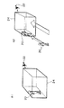
例えば図2のA1に示すように、キャラクタ20の後方であってキャラクタ20と視点22との間に所与のエリア24を設ける。このエリア24は、A2に示すようにキャラクタ20が移動するとそれに追従して移動する(視点22も追従する)。即ち、エリア24の位置は、キャラクタ20の位置により特定される。そして、図3のB1、B2に示すように、キャラクタ(第1のオブジェクト)20が移動することで、障害物となるオブジェクト(第2のオブジェクト)30がエリア24内に入ると、オブジェクト30の画像が変更される。より具体的には、オブジェクト30が透過表示(非表示)になる。また、図3のB3、B4に示すように、オブジェクト30の方が移動してエリア24に入っても、オブジェクト30が透過表示になる。
【0034】
このように、キャラクタ20の後方に、その中に入り込んだオブジェクト30が透過表示(或いは半透明表示、メッシュ表示)になるエリア24を設けることで、オブジェクト30が視点障害物となってキャラクタ20やその周囲がプレーヤから見えなくなる事態を防止できる。即ち図13(A)、(B)に示す問題を解決できる。しかも、図3の手法では、キャラクタ(第1のオブジェクト)20とオブジェクト30(第2のオブジェクト)との位置関係だけを調べればよい。したがって、キャラクタと視点との間にオブジェクトが入り込んだか否かを判定しなければならない(キャラクタと視点とオブジェクトの位置関係を調べなければならない)特開平9−50541号公報の従来技術に比べて、処理負担や処理時間を格段に軽減できる。
【0035】
なお、エリア24の形状としては様々なものを考えることができる。例えば図4のC1、C2では、エリア24は扇形となっている。そして、この扇形のエリア24にオブジェクト30が入り込むと、オブジェクト30の画像が変更される(透過表示等になる)。このようにエリア24の形状として扇形を採用すると、処理負担や処理時間を更に軽減できる。即ち、オブジェクト30がエリア24に入り込んだか否かは、扇形の中心C(キャラクタ20の位置Pにより特定される)とオブジェクト30の位置(例えば代表点)Dとの距離、及びCとDを結ぶベクトルの方向を調べれば判断できるからである。
【0036】
なお、Z座標(高さ方向の座標)も考慮してオブジェクト30がエリア24に入り込んだか否かを判断する場合には、エリア24は、四角錐又は円錐であることが望ましい。
【0037】
また、図4のC1、C2では、エリア24の場所は、キャラクタ(第1のオブジェクト)20の位置(例えば代表点)Pにより特定されている。即ち、図4のC1、C2では、エリア24の扇形の中心Cはキャラクタ20の位置Pと一致するようになっており(ずらすようにしても構わない)、キャラクタ20が移動すると扇形のエリア24も移動する。つまり、エリア24は、キャラクタ20に付随している。
【0038】
しかしながら、エリア24の場所を、オブジェクト(第2のオブジェクト)30の位置により特定するようにしてもよい。例えば、図4のC3、C4では、エリア24の扇形の中心Cはオブジェクト30の位置Dと一致するようになっており、オブジェクト30の位置Dによりエリア24の場所が特定されている。即ち、エリア24は、キャラクタ20ではなくオブジェクト30に付随している。そして、図4のC1、C2では、オブジェクト30がエリア24に入り込んだ場合にオブジェクト30の画像が変更されていたが、C3、C4では、キャラクタ20がエリア24に入り込んだ場合にオブジェクト30の画像が変更される。
【0039】
このように、第1、第2のオブジェクトの位置関係に基づいて第2のオブジェクトの画像を変更する本実施形態の手法は、視点障害物を透過表示にする以外にも、種々の応用が可能である。
【0040】
例えば特開平9−50541号公報の従来技術では、キャラクタと視点との間に入り込んだ邪魔なオブジェクトしか透過表示にできなかったが、本実施形態によれば、図4のC4に示すように、キャラクタ20の前にあり障害物となっているオブジェクト30を透過表示にすることができるようになる。
【0041】
また、例えばキャラクタ20がエリア24に入り込んだ場合に、オブジェクト30の輝度を変更するようにすれば、懐中電灯を持って歩くキャラクタの前にあるオブジェクトを光らせるなどの画像表現が簡易な処理で実現できるようになる。このような画像表現は、通常、懐中電灯を光源とするシェーディング演算を行うという、非常に負担の重い処理により実現される。しかしながら、本実施形態によれば、キャラクタ20がエリア24に入り込んだかを判断し、入り込んだ場合にはオブジェクト30の輝度を変更するという、非常に負担の軽い処理でこのような画像表現を実現できるようになる。
【0042】
このように、本実施形態の手法は、視点障害物を透過表示にする応用例しかない特開平9−50541号公報の従来技術に比べて、種々の画像表現への応用が可能であるという利点を有する。
【0043】
なお、図4のC3、C4では、エリア24を扇形にしているが、円、多角形、四角錐、円錐などにすることもできる。但し、エリア24を扇形にすれば前述のように処理負担、処理時間を軽減できる。また、キャラクタ20がオブジェクト30の右側や左側にきた場合にオブジェクト30の画像が変更されてしまうと、プレーヤに不自然感を与えるという問題が生じるが、エリア24を扇形にすれば、C3に示すように、このような問題を解決できる。
【0044】
また、図4のC5、C6に示すように、扇形の中心Cをオブジェクト30の外側に設けると共に、オブジェクト30に重なり合うようにエリア24を設けるようにしてもよい。このようにすれば、オブジェクト30の手前にキャラクタ20がいる場合にオブジェクト30を透明表示にできるようになると共に(図4のC5)、キャラクタ20と視点22の間にオブジェクト30がある場合にもオブジェクト30を透明表示にできるようになる(C6)。即ち、図4のC1及びC2と、C3及びC4の両方の特徴を兼ね備えることができるようになる。
【0045】
また、図5のD1、D2、D3に示すように、オブジェクト30の位置Dと扇形の中心Cとの距離LDや、扇形の半径Rや、扇形の中心角αは、オブジェクト30の種類(形状、大きさ)に応じて変えるようにすることが望ましい。例えば奥行きのあるオブジェクトについては距離LDや半径Rを大きくし、幅の大きいオブジェクトについては中心角αを大きくする。このようにすることで、各オブジェクトに対するエリアの設定を、各オブジェクトに最適となるように調整できるようになる。これにより、プレーヤが感じる不自然さがより少ない画像を生成できるようになる。
【0046】
次に本実施形態が適用される対戦ゲームの例について説明する。
【0047】
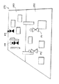
図6に示すように、この対戦ゲームでは、各キャラクタは、しゃがんだり、ジャンプしたり、高い場所に上ったり、ゲームフィールド270上で移動したりすることができる。そして、キャラクタP1、P2はペアを組み、対戦相手であるキャラクタP3、P4のペアと対戦する。ゲームフィールド270には、いくつもの障害物が配置されている。キャラクタはこれらの障害物に隠れたりしながら、銃を用いた銃撃戦により敵と対戦する。
【0048】
ここで、ゲームフィールド270は、第1の陣地250と第2の陣地260に分かれている。そして、キャラクタP1、P2は第1の陣地250内でのみ移動可能であり、キャラクタP3、P4は第2の陣地260内でのみ移動可能になっている。このように移動範囲を制限することで、敵が常に正面に位置するようになり、敵の位置が把握しやすくなる。また、敵が背後から回り込んでくることがなくなるため、見えない位置から攻撃されるという理不尽な状況を解消できる。したがって、ゲームフィールド270内の全ての領域を自由に移動できるゲームに比べて、プレーヤが非常にゲームプレイしやすいゲームを実現できるようになる。
【0049】
図7(A)、(B)、図8に、本実施形態により生成されるゲーム画像の例を示す。図7(A)では、キャラクタ20はオブジェクト(障害物)30の手前側に隠れている。この場合、キャラクタ20とオブジェクト30との距離が離れているため、オブジェクト30の画像は変更されない。
【0050】
これに対して、図7(B)では、キャラクタ20とオブジェクト30との距離が近づいたため、オブジェクト30の画像が変更されメッシュ表示(1又は複数画素毎にオブジェクト30の画像を表示する)になる(図4のC5参照)。これにより、キャラクタ20を操作するプレーヤは、オブジェクト30の向こう側の様子を把握できるようになる。
【0051】
即ち、画像のリアル性を重視するならば、図7(B)のような場合にオブジェクト30の向こう側が見えることは、あまり望ましくない。
【0052】
しかしながら、この種の3次元ゲームには、自分の周りの状況を把握することが難しくゲームプレイが難しいため、初心者やゲーム操作に自信のない人に敬遠されてしまうという欠点がある。したがって、画像のリアル性をある程度犠牲にしても、プレーヤがゲームプレイしやすいゲーム環境を提供することが望ましい。図6のように陣地を分けたのも、このような目的を達成するためである。そして、本実施形態では、図7(B)のような場合にオブジェクト30をメッシュ表示しているため、プレーヤは、オブジェクト30の向こう側の状況を把握できるようになる。この結果、プレーヤが更にゲームプレイしやすいゲーム環境を提供できるようになる。
【0053】
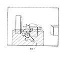
一方、図8では、キャラクタ20はオブジェクト30の向こう側に位置している。この時、本実施形態では、キャラクタ20がプレーヤから見えるようにオブジェクト30をメッシュ表示にしている(図4のC6参照)。これにより、オブジェクト30が障害物になってキャラクタ20がプレーヤから見えなくなる事態を防止できるようになる。
【0054】
次に本実施形態の詳細な処理例について、図9のフローチャートを用いて説明する。
【0055】
まず、キャラクタ20の位置P(図10参照)を算出する(ステップS1)。この位置Pは、プレーヤからの操作データ等に基づいて図1の移動体演算部112が各フレーム毎に算出するものである。
【0056】
次に、位置Pと扇形(エリア24)の中心Cとの距離LPを算出する(ステップS2)。ここで、位置PはステップS1により算出されている。また、中心Cは、オブジェクト30の位置(代表点)Dから特定される。
【0057】
次に、ステップS2で得られた距離LPが、扇形(エリア24)の半径Rよりも小さいか否かを判断する(ステップS3)。そして、大きい場合には、キャラクタ20はエリア24の外側にあると判断できるため処理を終了する。一方、小さい場合には次のステップに移行する。
【0058】
次に、CとPを結ぶベクトルの方向とCとDを結ぶベクトルの方向のなす角度θを算出する(ステップS4)。そして、角度θの絶対値が、α/2(αは扇形の中心角)よりも小さいか否かを判断する(ステップS5)。そして、大きい場合には、キャラクタ20はエリア24の外側にあると判断できるため処理を終了する。一方、小さい場合には、キャラクタ20はエリア24の内側にあると判断できるため、オブジェクト30の画像を変更する(ステップS6)。即ち、オブジェクト30を、透過表示、半透明表示、或いはメッシュ表示にしたり、オブジェクト30の形状、色、輝度、或いはテクスチャを変更したり、オブジェクト30を別のオブジェクトに切り替えたりする。
【0059】
以上の本実施形態によれば、視点障害物の問題を解決できるのみならず、例えば図7(B)に示すような様々な映像効果を得ることができるようになる。
【0060】
次に、本実施形態を実現できるハードウェアの構成の一例について図11を用いて説明する。同図に示す装置では、CPU1000、ROM1002、RAM1004、情報記憶媒体1006、音生成IC1008、画像生成IC1010、I/Oポート1012、1014が、システムバス1016により相互にデータ送受信可能に接続されている。そして前記画像生成IC1010にはディスプレイ1018が接続され、音生成IC1008にはスピーカ1020が接続され、I/Oポート1012にはコントロール装置1022が接続され、I/Oポート1014には通信装置1024が接続されている。
【0061】
情報記憶媒体1006は、プログラム、表示物を表現するための画像データ、音データ等が主に格納されるものである。例えば家庭用ゲーム装置ではゲームプログラム等を格納する情報記憶媒体としてCD−ROM、ゲームカセット、DVD等が用いられる。また業務用ゲーム装置ではROM等のメモリが用いられ、この場合には情報記憶媒体1006はROM1002になる。
【0062】
コントロール装置1022はゲームコントローラ、操作パネル等に相当するものであり、プレーヤがゲーム進行に応じて行う判断の結果を装置本体に入力するための装置である。
【0063】
情報記憶媒体1006に格納されるプログラム、ROM1002に格納されるシステムプログラム(装置本体の初期化情報等)、コントロール装置1022によって入力される信号等に従って、CPU1000は装置全体の制御や各種データ処理を行う。RAM1004はこのCPU1000の作業領域等として用いられる記憶手段であり、情報記憶媒体1006やROM1002の所与の内容、あるいはCPU1000の演算結果等が格納される。また本実施形態を実現するための論理的な構成を持つデータ構造(例えばオブジェクトのデータ構造)は、このRAM又は情報記憶媒体上に構築されることになる。
【0064】
更に、この種の装置には音生成IC1008と画像生成IC1010とが設けられていてゲーム音やゲーム画像の好適な出力が行えるようになっている。音生成IC1008は情報記憶媒体1006やROM1002に記憶される情報に基づいて効果音やバックグラウンド音楽等のゲーム音を生成する集積回路であり、生成されたゲーム音はスピーカ1020によって出力される。また、画像生成IC1010は、RAM1004、ROM1002、情報記憶媒体1006等から送られる画像情報に基づいてディスプレイ1018に出力するための画素情報を生成する集積回路である。なおディスプレイ1018として、いわゆるヘッドマウントディスプレイ(HMD)と呼ばれるものを使用することもできる。
【0065】
また、通信装置1024はゲーム装置内部で利用される各種の情報を外部とやりとりするものであり、他のゲーム装置と接続されてゲームプログラムに応じた所与の情報を送受したり、通信回線を介してゲームプログラム等の情報を送受することなどに利用される。
【0066】
そして図1〜図8、図10で説明した種々の処理は、図9のフローチャートに示した処理等を行うプログラムを格納した情報記憶媒体1006と、該プログラムに従って動作するCPU1000、画像生成IC1010、音生成IC1008等によって実現される。なお画像生成IC1010、音生成IC1008等で行われる処理は、CPU1000あるいは汎用のDSP等によりソフトウェア的に行ってもよい。
【0067】
図12(A)に、本実施形態を業務用ゲーム装置に適用した場合の例を示す。プレーヤは、ディスプレイ1100上に映し出されたゲーム画像を見ながら、レバー1102、ボタン1104を操作してゲームを楽しむ。装置に内蔵されるIC基板1106には、CPU、画像生成IC、音処理IC等が実装されている。そして、第1、第2のオブジェクトを含む複数のオブジェクトが配置されるオブジェクト空間を形成するための情報、前記第1のオブジェクトと前記第2のオブジェクトとの位置関係に基づいて前記第2のオブジェクトの画像を変更するための情報、オブジェクト空間内の所与の視点での画像を生成するための情報、前記第1のオブジェクトの位置により特定される所与のエリアに前記第2のオブジェクトが入った場合に、前記第2のオブジェクトの画像を変更するための情報、前記第2のオブジェクトの位置により特定される所与のエリアに前記第1のオブジェクトが入った場合に、前記第2のオブジェクトの画像を変更するための情報等は、IC基板1106上の情報記憶媒体であるメモリ1108に格納される。以下、これらの情報を格納情報と呼ぶ。これらの格納情報は、上記の種々の処理を行うためのプログラムコード、画像情報、音情報、表示物の形状情報、テーブルデータ、リストデータ、プレーヤ情報等の少なくとも1つを含むものである。
【0068】
図12(B)に、本実施形態を家庭用のゲーム装置に適用した場合の例を示す。プレーヤはディスプレイ1200に映し出されたゲーム画像を見ながら、ゲームコントローラ1202、1204を操作してゲームを楽しむ。この場合、上記格納情報は、本体装置に着脱自在な情報記憶媒体であるCD−ROM1206、ICカード1208、1209等に格納されている。
【0069】
図12(C)に、ホスト装置1300と、このホスト装置1300と通信回線1302を介して接続される端末1304-1〜1304-nとを含むゲーム装置に本実施形態を適用した場合の例を示す。この場合、上記格納情報は、例えばホスト装置1300が制御可能な磁気ディスク装置、磁気テープ装置、メモリ等の情報記憶媒体1306に格納されている。端末1304-1〜1304-nが、CPU、画像生成IC、音処理ICを有し、スタンドアロンでゲーム画像、ゲーム音を生成できるものである場合には、ホスト装置1300からは、ゲーム画像、ゲーム音を生成するためのゲームプログラム等が端末1304-1〜1304-nに配送される。一方、スタンドアロンで生成できない場合には、ホスト装置1300がゲーム画像、ゲーム音を生成し、これを端末1304-1〜1304-nに伝送し端末において出力することになる。
【0070】
なお本発明は、上記実施形態で説明したものに限らず、種々の変形実施が可能である。
【0071】
例えば、第1、第2のオブジェクトの位置関係に基づいて第2のオブジェクトの画像を変更する発明は、図3、図4で説明したものに限定されず、種々の変形実施が可能である。
【0072】
また、本実施形態では、第1のオブジェクトが、オブジェクト空間内を移動するキャラクタなどの移動体であり、第2のオブジェクトが、オブジェクト空間内でその位置が固定される障害物などの固定物である場合について説明した。しかしながら、本発明の第1、第2のオブジェクトは、このようなものに限定されるものではなく、例えば、第1のオブジェクトを固定物とし、第2のオブジェクトを移動体としたり、第1、第2のオブジェクトを共に移動体にしたりすることが可能である。
【0073】
また、第2のオブジェクトの画像変更処理としては、例えば、第2のオブジェクトを透過表示、半透明表示、或いはメッシュ表示にしたり、第2のオブジェクトを他のオブジェクトに切り替えたり、第2のオブジェクトの形状、色、輝度、或いはテクスチャを変更する処理を考えることができる。しかしながら、本発明の画像変更処理はこれに限定されるものではない。
【0074】
また本実施形態では本発明をキャラクタ同士の対戦ゲームに適用した場合について説明したが、本発明はこれに限らず種々のゲーム(格闘技ゲーム、ロールプレイングゲーム、シューティングゲーム、スポーツゲーム、競争ゲーム等)に適用できる。
【0075】
また本発明は、家庭用、業務用のゲーム装置のみならず、シミュレータ、多数のプレーヤが参加する大型アトラクション装置、パーソナルコンピュータ、マルチメディア端末、ゲーム画像を生成するシステム基板等の種々の画像生成装置にも適用できる。
【0076】
【図面の簡単な説明】
【図1】本実施形態の画像生成装置の機能ブロック図の一例である。
【図2】キャラクタとエリアとの関係を説明するための図である。
【図3】キャラクタの後方に設けられたエリアに入り込んだオブジェクトを透過表示にする手法について説明するための図である。
【図4】本実施形態の原理及び種々の応用例について説明するための図である。
【図5】扇形の半径、中心角などをオブジェクト毎に変える手法について説明するための図である。
【図6】本実施形態により実現される対戦ゲームのゲームフィールドについて説明するための図である。
【図7】図7(A)、(B)は、本実施形態により生成される画像の例について示す図である。
【図8】本実施形態により生成される画像の例について示す図である。
【図9】本実施形態の詳細な処理例を説明するためのフローチャートである。
【図10】キャラクタとオブジェクトとエリアとの位置関係について示す図である。
【図11】本実施形態を実現できるハードウェアの構成の一例を示す図である。
【図12】図12(A)、(B)、(C)は、本実施形態が適用される種々の形態の装置の例を示す図である。
【図13】図13(A)、(B)は、視点障害物の問題について説明するための図である。
【符号の説明】
10 操作部
12 表示部
20 キャラクタ(第1のオブジェクト)
22 視点
24 エリア
30 オブジェクト(第2のオブジェクト)
100 処理部
110 ゲーム演算部
111 オブジェクト空間形成部
112 移動体演算部
114 画像変更部
150 画像生成部
190 情報記憶媒体[0001]
BACKGROUND OF THE INVENTION
The present invention relates to an image generation apparatus and an information storage medium that generate an image at a given viewpoint in an object space.
[0002]
[Background Art and Problems to be Solved by the Invention]
2. Description of the Related Art Conventionally, image generation apparatuses that arrange a plurality of objects in an object space that is a virtual three-dimensional space and generate an image that can be viewed from a given viewpoint in the object space have been developed and put into practical use. It is popular as a way to experience reality. Taking an image generation device capable of enjoying a competitive game as an example, a player moves a character (human, robot, etc.) operated by the player in the object space and battles with a character operated by another player or a computer. Enjoy a 3D game.
[0003]
Now, in such an image generating apparatus, as shown in FIG. 13 (A), when an
[0004]
As a conventional technique for solving such a problem, for example, a technique disclosed in JP-A-9-50541 is known. In this conventional technique, it is determined whether or not an object that becomes an obstacle has entered between the viewpoint and the character, and when it is determined that the object has entered, the object is transparently displayed to solve the above problem. .
[0005]
However, in this prior art, it is necessary to determine whether or not an object has entered based on three positions: a viewpoint position, a character position, and an obstacle object position. Therefore, there is a problem that the processing load and the processing time become excessive.
[0006]
In addition, this conventional technique also has a problem that there is no other application example except that the viewpoint obstacle is transparently displayed.
[0007]
The present invention has been made in view of the technical problems as described above, and an object of the present invention is to provide an image generation apparatus capable of various image expression only by examining the positional relationship between two objects, and An object is to provide an information storage medium.
[0008]
Another object of the present invention is to provide an image generation apparatus and an information storage medium that can prevent a situation in which an object to be watched cannot be seen because another object becomes a viewpoint obstacle.
[0009]
[Means for Solving the Problems]
In order to solve the above-described problem, the present invention is an image generation apparatus that generates an image at a given viewpoint in an object space, and an object in which a plurality of objects including first and second objects are arranged. Means for forming a space; means for changing an image of the second object based on a positional relationship between the first object and the second object; and an image at a given viewpoint in the object space. Generating means.
[0010]
According to the present invention, an object space in which objects such as a moving object, a map, and a background are arranged is formed. Then, it is determined what the positional relationship between the first and second objects among these objects is, and the image of the second object is changed based on the positional relationship. For example, when the first object is a character and the second object is an obstacle, the obstacle is displayed transparently, translucently, or meshed according to the positional relationship between the character and the obstacle. Shape, color, brightness, texture, etc. are changed. By doing this, for example, it is possible to solve the problem that the obstacle becomes obstructive and the character behind the obstacle can not be seen from the viewpoint, or to make the game play easier by making the other side of the obstacle visible Is possible. In particular, according to the present invention, the image of the second object can be changed only by the positional relationship between the first and second objects without considering the position of the viewpoint. Can be greatly reduced.
[0011]
Further, the present invention is characterized in that when the second object enters a given area specified by the position of the first object, the image of the second object is changed. Here, as the position of the first object, for example, a representative point of the first object can be considered. In the given area, the place where the first object is provided is specified by the position of the first object. When the given area is, for example, a circle or a sector, the position of the first object or a position away from the position by a given distance can be set as the center of the circle or the sector. In addition, when the first object is a moving body, a given area can be moved following the movement. According to the present invention, when the second object enters such a given area, the image of the second object is changed. That is, an area where the image of the second object is changed can be provided in association with the first object.
[0012]
Further, the present invention is characterized in that the given area is provided between the first object and a viewpoint that follows the first object. According to the present invention, the viewpoint follows the movement of the first object. The position of the given area is determined in advance so that the given area is interposed between the first object and the viewpoint that follows the first object. Then, when the second object enters the given area, the image of the second object is changed. In this case, whether or not to change the image is determined by the positional relationship between the first and second objects without considering the position of the viewpoint. Therefore, according to the present invention, the second object that has entered between the first object and the viewpoint is determined only by determining the positional relationship between the first and second objects and not the position of the viewpoint. Can be made transparent display, translucent display, or mesh display. Therefore, it is possible to solve the problem of the viewpoint obstacle with much less processing load and processing time than the conventional technique that determines not only the first and second objects but also the positional relationship of the viewpoint.
[0013]
In the invention, it is preferable that the given area has a sector shape whose center is specified by the position of the first object. In this way, it is possible to determine whether or not the second object has entered a given area with simple and low-load processing.
[0014]
The present invention is characterized in that when the first object enters a given area specified by the position of the second object, the image of the second object is changed. Here, as the position of the second object, for example, a representative point of the second object can be considered. In a given area, the location where the second object is provided is specified by the position of the second object. For example, when a given area is a circle or a sector, the position of the second object or a position away from the position by a given distance can be set as the center of the circle or sector. According to the present invention, when the first object enters such a given area, the image of the second object is changed. That is, an area where the image of the second object is changed can be provided in association with the second object itself.
[0015]
In the invention, it is preferable that the given area has a sector shape whose center is specified by the position of the second object. In this way, it is possible to determine whether or not the first object has entered a given area with simple and low-load processing.
[0016]
Furthermore, the present invention is characterized in that the center is located outside the second object, and the given area in the shape of a sector overlaps the second object. In this way, even when the first object enters the part of the given area beyond the second object (the side with the fan-shaped center), the front side of the second object ( Even when the first object enters the portion on the side having the fan-shaped arc, the image of the second object can be changed.
[0017]
According to the present invention, at least one of the distance between the position of the second object and the center, the radius of the sector, and the central angle of the sector is changed according to the type of the second object. And In this way, an appropriate sector area can be set for each second object according to the type (size, shape) of the second object.
[0018]
In the present invention, it is desirable that the first object is a moving body that moves in the object space, and the second object is a fixed object whose position is fixed in the object space. .
[0019]
The processing for changing the image of the second object includes processing for making the second object transparent display, processing for making the second object semi-transparent display, and making the second object mesh display. Processing to switch the second object to another object, processing to change the shape of the second object, processing to change the color of the second object, and change the luminance of the second object A process and a process of changing the texture of the second object can be considered.
[0020]
DETAILED DESCRIPTION OF THE INVENTION
Hereinafter, preferred embodiments of the present invention will be described with reference to the drawings. In the following, the case where the present invention is applied to a game in which a plurality of characters are divided into enemies and allies will be described as an example, but the present invention is not limited to this and can be applied to various games.
[0021]
FIG. 1 shows an example of a functional block diagram of the image generation apparatus of the present embodiment.
[0022]
Here, the
[0023]
The
[0024]
The
[0025]
The
[0026]
Here, the
[0027]
The
[0028]
The
[0029]
Here, the object space forming unit 111 performs processing for arranging various objects such as characters, enemy characters (targets), maps, and backgrounds in the object space. More specifically, the arrangement and type of the map and background objects are determined for each game stage, and calculations for moving a moving body (character, target, shot, etc.) in the object space are performed.
[0030]
The object space forming unit 111 includes a moving
[0031]
Here, based on the operation data input from the
[0032]
The image changing unit 114 determines the positional relationship between the first object and the second object, and performs processing for changing the image of the second object based on the positional relationship. More specifically, the following processing is performed.
[0033]
For example, as shown by A1 in FIG. 2, a given
[0034]
As described above, by providing the
[0035]
Various shapes of the
[0036]
When determining whether or not the
[0037]
4, the location of the
[0038]
However, the location of the
[0039]
As described above, the method of the present embodiment that changes the image of the second object based on the positional relationship between the first and second objects can be applied to various applications in addition to displaying the viewpoint obstacle transparently. It is.
[0040]
For example, in the prior art disclosed in Japanese Patent Laid-Open No. 9-50541, only disturbing objects that have entered between the character and the viewpoint can be transparently displayed. However, according to the present embodiment, as indicated by C4 in FIG. The
[0041]
Further, for example, when the
[0042]
Thus, the method of the present embodiment has an advantage that it can be applied to various image representations as compared with the prior art disclosed in Japanese Patent Laid-Open No. 9-50541, which has only an application example in which a viewpoint obstacle is transmissively displayed. Have
[0043]
In C3 and C4 in FIG. 4, the
[0044]
Further, as shown by C5 and C6 in FIG. 4, the sector-shaped center C may be provided outside the
[0045]
5, the distance LD between the position D of the
[0046]
Next, an example of a battle game to which the present embodiment is applied will be described.
[0047]
As shown in FIG. 6, in this competitive game, each character can squat, jump, climb to a high place, or move on the
[0048]
Here, the
[0049]
7A, 7B, and 8 show examples of game images generated by the present embodiment. In FIG. 7A, the
[0050]
On the other hand, in FIG. 7B, since the distance between the
[0051]
That is, if importance is attached to the realism of the image, it is not so desirable that the other side of the
[0052]
However, this type of three-dimensional game has a drawback in that it is difficult to grasp the situation around you and it is difficult to play a game, so that it is avoided by beginners and those who are not confident in game operation. Therefore, it is desirable to provide a game environment in which the player can easily play the game even if the realism of the image is sacrificed to some extent. The reason why the positions are divided as shown in FIG. 6 is to achieve such a purpose. In this embodiment, since the
[0053]
On the other hand, in FIG. 8, the
[0054]
Next, a detailed processing example of this embodiment will be described with reference to the flowchart of FIG.
[0055]
First, the position P (see FIG. 10) of the
[0056]
Next, a distance LP between the position P and the center C of the sector (area 24) is calculated (step S2). Here, the position P is calculated in step S1. The center C is specified from the position (representative point) D of the
[0057]
Next, it is determined whether or not the distance LP obtained in step S2 is smaller than the radius R of the sector (area 24) (step S3). If it is larger, it can be determined that the
[0058]
Next, an angle θ formed by the direction of the vector connecting C and P and the direction of the vector connecting C and D is calculated (step S4). Then, it is determined whether or not the absolute value of the angle θ is smaller than α / 2 (α is a sector central angle) (step S5). If it is larger, it can be determined that the
[0059]
According to the present embodiment described above, not only the problem of the viewpoint obstacle can be solved, but also various video effects as shown in FIG. 7B can be obtained.
[0060]
Next, an example of a hardware configuration capable of realizing the present embodiment will be described with reference to FIG. In the apparatus shown in the figure, a
[0061]
The
[0062]
The
[0063]
In accordance with a program stored in the
[0064]
Further, this type of apparatus is provided with a
[0065]
The
[0066]
The various processes described in FIGS. 1 to 8 and 10 include an
[0067]
FIG. 12A shows an example in which the present embodiment is applied to an arcade game device. The player enjoys the game by operating the
[0068]
FIG. 12B shows an example in which the present embodiment is applied to a home game device. The player enjoys the game by operating the
[0069]
FIG. 12C shows an example in which the present embodiment is applied to a game device including a
[0070]
The present invention is not limited to that described in the above embodiment, and various modifications can be made.
[0071]
For example, the invention for changing the image of the second object based on the positional relationship between the first and second objects is not limited to that described with reference to FIGS. 3 and 4, and various modifications can be made.
[0072]
In the present embodiment, the first object is a moving object such as a character that moves in the object space, and the second object is a fixed object such as an obstacle whose position is fixed in the object space. I explained a case. However, the first and second objects of the present invention are not limited to such objects. For example, the first object is a fixed object and the second object is a moving object, or the first, It is possible to make the second object a moving object together.
[0073]
In addition, as the image change processing of the second object, for example, the second object is displayed in a transparent display, a semi-transparent display, or a mesh display, the second object is switched to another object, A process of changing the shape, color, brightness, or texture can be considered. However, the image change process of the present invention is not limited to this.
[0074]
Moreover, although this embodiment demonstrated the case where this invention was applied to the battle game between characters, this invention is not limited to this, A variety of games (a martial arts game, a role-playing game, a shooting game, a sports game, a competition game, etc.) Applicable to.
[0075]
The present invention is not limited to home and business game devices, but also various image generation devices such as a simulator, a large attraction device in which a large number of players participate, a personal computer, a multimedia terminal, and a system board for generating game images. It can also be applied to.
[0076]
[Brief description of the drawings]
FIG. 1 is an example of a functional block diagram of an image generation apparatus according to an embodiment.
FIG. 2 is a diagram for explaining a relationship between a character and an area.
FIG. 3 is a diagram for explaining a technique for transparently displaying an object that has entered an area provided behind a character.
FIG. 4 is a diagram for explaining the principle of the present embodiment and various application examples.
FIG. 5 is a diagram for explaining a method of changing a sector radius, a center angle, and the like for each object.
FIG. 6 is a diagram for describing a game field of a battle game realized by the present embodiment.
FIGS. 7A and 7B are diagrams illustrating examples of images generated according to the present embodiment.
FIG. 8 is a diagram illustrating an example of an image generated according to the present embodiment.
FIG. 9 is a flowchart for explaining a detailed processing example of the present embodiment;
FIG. 10 is a diagram illustrating a positional relationship among a character, an object, and an area.
FIG. 11 is a diagram illustrating an example of a hardware configuration capable of realizing the present embodiment.
FIGS. 12A, 12B, and 12C are diagrams illustrating examples of various types of apparatuses to which the present embodiment is applied.
FIGS. 13A and 13B are diagrams for explaining the problem of viewpoint obstacles. FIG.
[Explanation of symbols]
10 Operation part
12 Display section
20 characters (first object)
22 viewpoints
24 areas
30 objects (second objects)
100 processor
110 Game calculation part
111 Object space forming part
112 Mobile object calculation unit
114 Image change section
150 Image generator
190 Information storage media
Claims (7)
第1、第2のオブジェクトを含む複数のオブジェクトが配置されるオブジェクト空間を形成するオブジェクト空間形成手段と、
前記第1のオブジェクトをオブジェクト空間内で移動させる演算を行う移動体演算手段と、
前記第1のオブジェクトの所定方向に設定される視点を、前記第1のオブジェクトの移動に追従させてオブジェクト空間内で移動させる演算を行う手段と、
前記第1のオブジェクトの所定方向に前記第1のオブジェクトと所定の位置関係を構築する所与のエリアを設定し、前記第1のオブジェクトと前記第2のオブジェクトとの位置関係に基づいて、所与のエリアに前記第2のオブジェクトが入ったか否かを判断し、所与のエリアに前記第2のオブジェクトが入ったと判断された場合に、前記第2のオブジェクトの画像を変更する画像変更手段と、
オブジェクト空間内の所与の視点での画像を生成する画像生成手段とを含むことを特徴とする画像生成装置。An image generation device that generates an image at a given viewpoint in an object space,
An object space forming means for forming an object space in which a plurality of objects including the first and second objects are arranged;
Moving body computing means for performing computation to move the first object in the object space;
Means for performing an operation of moving a viewpoint set in a predetermined direction of the first object in the object space by following the movement of the first object;
A predetermined area for establishing a predetermined positional relationship with the first object is set in a predetermined direction of the first object, and based on the positional relationship between the first object and the second object , Image changing means for determining whether or not the second object has entered the given area, and changing the image of the second object when it is determined that the second object has entered the given area When,
An image generation apparatus comprising: an image generation unit configured to generate an image at a given viewpoint in an object space.
前記画像変更手段が、
前記第1のオブジェクトの位置により中心が特定される扇形の所与のエリアに、前記第2のオブジェクトが入った場合に、前記第2のオブジェクトの画像を変更することを特徴とする画像生成装置。In claim 1 ,
The image changing means is
An image generating apparatus that changes an image of the second object when the second object enters a given sector-shaped area whose center is specified by the position of the first object. .
第1、第2のオブジェクトを含む複数のオブジェクトが配置されるオブジェクト空間を形成するオブジェクト空間形成手段と、
前記第1のオブジェクトをオブジェクト空間内で移動させる演算を行う移動体演算手段と、
中心及び弧が前記第2のオブジェクトの外側にあって前記第2のオブジェクトの位置により当該中心が特定されると共に、前記第2のオブジェクトに重なるように配置される扇形の所与のエリアを設定し、前記第1のオブジェクトと前記第2のオブジェクトとの位置関係に基づいて、所与のエリアに前記第1のオブジェクトが入ったか否かを判断し、所与のエリアに前記第1のオブジェクトが入ったと判断された場合に、前記第2のオブジェクトの画像を変更する画像変更手段と、
オブジェクト空間内の所与の視点での画像を生成する画像生成手段と、
前記第2のオブジェクトの位置と前記中心との距離、前記扇形の半径、及び前記扇形の中心角の少なくとも1つを、前記第2のオブジェクトの形状及び大きさの少なくとも一方に応じて設定する手段とを含むことを特徴とする画像生成装置。 An image generation device that generates an image at a given viewpoint in an object space,
An object space forming means for forming an object space in which a plurality of objects including the first and second objects are arranged;
Moving body computing means for performing computation to move the first object in the object space;
The center and the arc are outside the second object, the center is specified by the position of the second object, and a given sector-shaped area is arranged so as to overlap the second object. Then, based on the positional relationship between the first object and the second object, it is determined whether or not the first object has entered the given area, and the first object enters the given area. Image changing means for changing the image of the second object when it is determined that
Image generating means for generating an image at a given viewpoint in the object space;
Means for setting at least one of the distance between the position of the second object and the center, the radius of the sector, and the central angle of the sector according to at least one of the shape and size of the second object image generating device which comprises and.
前記第1のオブジェクトが、前記オブジェクト空間内において移動する移動体であり、前記第2のオブジェクトが、前記オブジェクト空間内においてその位置が固定される固定物であることを特徴とする画像生成装置。In any one of Claims 1 thru | or 3 ,
The image generation apparatus according to claim 1, wherein the first object is a moving body that moves in the object space, and the second object is a fixed object whose position is fixed in the object space.
前記第2のオブジェクトの画像を変更する処理が、
前記第2のオブジェクトを透過表示にする処理、前記第2のオブジェクトを半透明表示にする処理、前記第2のオブジェクトをメッシュ表示にする処理、前記第2のオブジェクトを他のオブジェクトに切り替える処理、前記第2のオブジェクトの形状を変更する処理、前記第2のオブジェクトの色を変更する処理、前記第2のオブジェクトの輝度を変更する処理、及び前記第2のオブジェクトのテクスチャを変更する処理の少なくとも1つであることを特徴とする画像生成装置。In any one of Claims 1 thru | or 4 ,
The process of changing the image of the second object includes
A process for making the second object transparent, a process for making the second object semi-transparent, a process for making the second object mesh display, a process for switching the second object to another object, At least one of processing for changing the shape of the second object, processing for changing the color of the second object, processing for changing the brightness of the second object, and processing for changing the texture of the second object One image generating apparatus characterized by being one.
第1、第2のオブジェクトを含む複数のオブジェクトが配置されるオブジェクト空間を形成するオブジェクト空間形成手段と、
前記第1のオブジェクトをオブジェクト空間内で移動させる演算を行う移動体演算手段と、
前記第1のオブジェクトの所定方向に設定される視点を、前記第1のオブジェクトの移動に追従させてオブジェクト空間内で移動させる演算を行う手段と、
前記第1のオブジェクトの所定方向に前記第1のオブジェクトと所定の位置関係を構築する所与のエリアを設定し、前記第1のオブジェクトと前記第2のオブジェクトとの位置関係に基づいて、所与のエリアに前記第2のオブジェクトが入ったか否かを判断し、所与のエリアに前記第2のオブジェクトが入ったと判断された場合に、前記第2のオブジェクトの画像を変更する画像変更手段と、
オブジェクト空間内の所与の視点での画像を生成する画像生成手段として、
コンピュータを機能させるプログラムを記憶した情報記憶媒体。A computer-readable information storage medium for generating an image at a given viewpoint in an object space,
An object space forming means for forming an object space in which a plurality of objects including the first and second objects are arranged;
Moving body computing means for performing computation to move the first object in the object space;
Means for performing an operation of moving a viewpoint set in a predetermined direction of the first object in the object space by following the movement of the first object;
A predetermined area for establishing a predetermined positional relationship with the first object is set in a predetermined direction of the first object, and based on the positional relationship between the first object and the second object , Image changing means for determining whether or not the second object has entered the given area, and changing the image of the second object when it is determined that the second object has entered the given area When,
As an image generation means for generating an image at a given viewpoint in the object space,
An information storage medium storing a program that causes a computer to function.
オブジェクト空間内の所与の視点での画像を生成する画像生成装置であって、An image generation device that generates an image at a given viewpoint in an object space,
第1、第2のオブジェクトを含む複数のオブジェクトが配置されるオブジェクト空間を形成するオブジェクト空間形成手段と、Object space forming means for forming an object space in which a plurality of objects including the first and second objects are arranged;
前記第1のオブジェクトをオブジェクト空間内で移動させる演算を行う移動体演算手段と、Moving body computing means for performing computation to move the first object in the object space;
中心及び弧が前記第2のオブジェクトの外側にあって前記第2のオブジェクトの位置により当該中心が特定されると共に、前記第2のオブジェクトに重なるように配置される扇形の所与のエリアを設定し、前記第1のオブジェクトと前記第2のオブジェクトとの位置関係に基づいて、所与のエリアに前記第1のオブジェクトが入ったか否かを判断し、所与のエリアに前記第1のオブジェクトが入ったと判断された場合に、前記第2のオブジェクトの画像を変更する画像変更手段と、The center and the arc are outside the second object, the center is specified by the position of the second object, and a given sector-shaped area is arranged so as to overlap the second object. Then, based on the positional relationship between the first object and the second object, it is determined whether or not the first object has entered the given area, and the first object enters the given area. Image changing means for changing the image of the second object when it is determined that
オブジェクト空間内の所与の視点での画像を生成する画像生成手段と、Image generating means for generating an image at a given viewpoint in the object space;
前記第2のオブジェクトの位置と前記中心との距離、前記扇形の半径、及び前記扇形の中心角の少なくとも1つを、前記第2のオブジェクトの形状及び大きさの少なくとも一方に応じて設定する手段として、Means for setting at least one of the distance between the position of the second object and the center, the radius of the sector, and the central angle of the sector according to at least one of the shape and size of the second object As
コンピュータを機能させるプログラムを記憶した情報記憶媒体。An information storage medium storing a program that causes a computer to function.
Priority Applications (1)
| Application Number | Priority Date | Filing Date | Title |
|---|---|---|---|
| JP13138698A JP4114824B2 (en) | 1998-04-24 | 1998-04-24 | Image generating apparatus and information storage medium |
Applications Claiming Priority (1)
| Application Number | Priority Date | Filing Date | Title |
|---|---|---|---|
| JP13138698A JP4114824B2 (en) | 1998-04-24 | 1998-04-24 | Image generating apparatus and information storage medium |
Publications (2)
| Publication Number | Publication Date |
|---|---|
| JPH11306383A JPH11306383A (en) | 1999-11-05 |
| JP4114824B2 true JP4114824B2 (en) | 2008-07-09 |
Family
ID=15056753
Family Applications (1)
| Application Number | Title | Priority Date | Filing Date |
|---|---|---|---|
| JP13138698A Expired - Lifetime JP4114824B2 (en) | 1998-04-24 | 1998-04-24 | Image generating apparatus and information storage medium |
Country Status (1)
| Country | Link |
|---|---|
| JP (1) | JP4114824B2 (en) |
Families Citing this family (4)
| Publication number | Priority date | Publication date | Assignee | Title |
|---|---|---|---|---|
| JP4489800B2 (en) * | 2007-08-30 | 2010-06-23 | 株式会社スクウェア・エニックス | Image generating apparatus and method, program, and recording medium |
| JP6341759B2 (en) * | 2014-05-30 | 2018-06-13 | キヤノン株式会社 | Head-mounted information display device and control method for head-mounted information display device |
| JP6122047B2 (en) * | 2015-02-10 | 2017-04-26 | 株式会社カプコン | GAME PROGRAM AND GAME DEVICE |
| JP7304701B2 (en) * | 2019-01-28 | 2023-07-07 | 株式会社コーエーテクモゲームス | Game program, recording medium, game processing method |
Family Cites Families (3)
| Publication number | Priority date | Publication date | Assignee | Title |
|---|---|---|---|---|
| JP3251639B2 (en) * | 1992-06-08 | 2002-01-28 | 株式会社東芝 | Pointing device |
| JP3239683B2 (en) * | 1995-05-11 | 2001-12-17 | 株式会社セガ | Image processing apparatus and image processing method |
| JP3141737B2 (en) * | 1995-08-10 | 2001-03-05 | 株式会社セガ | Virtual image generation apparatus and method |
-
1998
- 1998-04-24 JP JP13138698A patent/JP4114824B2/en not_active Expired - Lifetime
Also Published As
| Publication number | Publication date |
|---|---|
| JPH11306383A (en) | 1999-11-05 |
Similar Documents
| Publication | Publication Date | Title |
|---|---|---|
| JP4974319B2 (en) | Image generation system, program, and information storage medium | |
| JP3183632B2 (en) | Information storage medium and image generation device | |
| JP6643775B2 (en) | Game machine, game system and program | |
| JP4187182B2 (en) | Image generation system, program, and information storage medium | |
| JP3707995B2 (en) | GAME SYSTEM AND INFORMATION STORAGE MEDIUM | |
| JP3747050B1 (en) | Program, information storage medium, and image generation system | |
| JP4707080B2 (en) | Image generation system, program, and information storage medium | |
| JP3786670B1 (en) | Program, information storage medium, and image generation system | |
| JP4508918B2 (en) | Image generation system and information storage medium | |
| JP4363595B2 (en) | Image generating apparatus and information storage medium | |
| JP2007105499A (en) | Game system, program and information storage medium | |
| JP4114824B2 (en) | Image generating apparatus and information storage medium | |
| JPH11146978A (en) | Three-dimensional game unit, and information recording medium | |
| JP2000288248A (en) | Game device and information storage medium | |
| JP4114825B2 (en) | Image generating apparatus and information storage medium | |
| JP5054908B2 (en) | Program, information storage medium, and image generation system | |
| JP4187192B2 (en) | Image generation system, program, and information storage medium | |
| JPH10113465A (en) | Game device, screen generating method, and information memory medium | |
| JP3482017B2 (en) | 3D game device and 3D game image generation method | |
| JP6931723B2 (en) | Game consoles, game systems and programs | |
| JP3827054B2 (en) | Image processing apparatus and game apparatus having the same | |
| JP4632521B2 (en) | GAME SYSTEM AND INFORMATION STORAGE MEDIUM | |
| JPH11244532A (en) | Image producing device and information storage medium | |
| JP4261211B2 (en) | GAME DEVICE AND INFORMATION STORAGE MEDIUM | |
| JP4069459B2 (en) | GAME DEVICE AND ITS CONTROL METHOD |
Legal Events
| Date | Code | Title | Description |
|---|---|---|---|
| A521 | Request for written amendment filed |
Free format text: JAPANESE INTERMEDIATE CODE: A523 Effective date: 20050425 |
|
| A621 | Written request for application examination |
Free format text: JAPANESE INTERMEDIATE CODE: A621 Effective date: 20050425 |
|
| A977 | Report on retrieval |
Free format text: JAPANESE INTERMEDIATE CODE: A971007 Effective date: 20071128 |
|
| A131 | Notification of reasons for refusal |
Free format text: JAPANESE INTERMEDIATE CODE: A131 Effective date: 20071212 |
|
| A521 | Request for written amendment filed |
Free format text: JAPANESE INTERMEDIATE CODE: A523 Effective date: 20080206 |
|
| TRDD | Decision of grant or rejection written | ||
| A01 | Written decision to grant a patent or to grant a registration (utility model) |
Free format text: JAPANESE INTERMEDIATE CODE: A01 Effective date: 20080409 |
|
| A61 | First payment of annual fees (during grant procedure) |
Free format text: JAPANESE INTERMEDIATE CODE: A61 Effective date: 20080411 |
|
| FPAY | Renewal fee payment (event date is renewal date of database) |
Free format text: PAYMENT UNTIL: 20110425 Year of fee payment: 3 |
|
| R150 | Certificate of patent or registration of utility model |
Free format text: JAPANESE INTERMEDIATE CODE: R150 |
|
| FPAY | Renewal fee payment (event date is renewal date of database) |
Free format text: PAYMENT UNTIL: 20110425 Year of fee payment: 3 |
|
| FPAY | Renewal fee payment (event date is renewal date of database) |
Free format text: PAYMENT UNTIL: 20110425 Year of fee payment: 3 |
|
| FPAY | Renewal fee payment (event date is renewal date of database) |
Free format text: PAYMENT UNTIL: 20110425 Year of fee payment: 3 |
|
| FPAY | Renewal fee payment (event date is renewal date of database) |
Free format text: PAYMENT UNTIL: 20120425 Year of fee payment: 4 |
|
| FPAY | Renewal fee payment (event date is renewal date of database) |
Free format text: PAYMENT UNTIL: 20130425 Year of fee payment: 5 |
|
| FPAY | Renewal fee payment (event date is renewal date of database) |
Free format text: PAYMENT UNTIL: 20130425 Year of fee payment: 5 |
|
| FPAY | Renewal fee payment (event date is renewal date of database) |
Free format text: PAYMENT UNTIL: 20140425 Year of fee payment: 6 |
|
| R250 | Receipt of annual fees |
Free format text: JAPANESE INTERMEDIATE CODE: R250 |
|
| R250 | Receipt of annual fees |
Free format text: JAPANESE INTERMEDIATE CODE: R250 |
|
| S531 | Written request for registration of change of domicile |
Free format text: JAPANESE INTERMEDIATE CODE: R313531 |
|
| R360 | Written notification for declining of transfer of rights |
Free format text: JAPANESE INTERMEDIATE CODE: R360 |
|
| S533 | Written request for registration of change of name |
Free format text: JAPANESE INTERMEDIATE CODE: R313533 |
|
| R370 | Written measure of declining of transfer procedure |
Free format text: JAPANESE INTERMEDIATE CODE: R370 |
|
| R350 | Written notification of registration of transfer |
Free format text: JAPANESE INTERMEDIATE CODE: R350 |
|
| S531 | Written request for registration of change of domicile |
Free format text: JAPANESE INTERMEDIATE CODE: R313531 |
|
| R350 | Written notification of registration of transfer |
Free format text: JAPANESE INTERMEDIATE CODE: R350 |
|
| R250 | Receipt of annual fees |
Free format text: JAPANESE INTERMEDIATE CODE: R250 |
|
| EXPY | Cancellation because of completion of term |