JP4187192B2 - Image generation system, program, and information storage medium - Google Patents
Image generation system, program, and information storage medium Download PDFInfo
- Publication number
- JP4187192B2 JP4187192B2 JP2002195810A JP2002195810A JP4187192B2 JP 4187192 B2 JP4187192 B2 JP 4187192B2 JP 2002195810 A JP2002195810 A JP 2002195810A JP 2002195810 A JP2002195810 A JP 2002195810A JP 4187192 B2 JP4187192 B2 JP 4187192B2
- Authority
- JP
- Japan
- Prior art keywords
- virtual
- virtual point
- image
- setting unit
- virtual camera
- Prior art date
- Legal status (The legal status is an assumption and is not a legal conclusion. Google has not performed a legal analysis and makes no representation as to the accuracy of the status listed.)
- Expired - Lifetime
Links
Images


Description
【0001】
【発明の属する技術分野】
本発明は、画像生成システム、プログラム及び情報記憶媒体に関する。
【0002】
【背景技術及び発明が解決しようとする課題】
従来より、仮想的な3次元空間であるオブジェクト空間内において所与の視点(仮想カメラ)から見える画像を生成する画像生成システム(ゲームシステム)が知られており、いわゆる仮想現実を体験できるものとして人気が高い。競争ゲーム(カーゲーム)を楽しむことができる画像生成システムを例にとれば、プレーヤは、操作部(ステアリング、シフトレバー、アクセルペダル、ブレーキペダル等)を用いてプレーヤ移動体(プレーヤカー、プレーヤオブジェクト)を操作し、コンピュータや相手プレーヤが操作する敵移動体(敵カー、敵オブジェクト)と競争することでゲームを楽しむ。
【0003】
このような画像生成システムでは、少ないデータ量で高品質な画像を生成するために、いわゆるビルボードと呼ばれる処理が行われる。このビルボード処理では、立体的に見える木、炎などの画像が描かれた板形状の多数のオブジェクト(平面ポリゴン)を、仮想カメラに正対するように配置することで、少ないデータ量で木、炎などの画像を生成する。このビルボード処理の従来技術としては例えば特開平8−501948がある。
【0004】
しかしながら、これまでのビルボード処理では、ビルボードのオブジェクトの向きを決定するのに、仮想カメラの視点位置や視線方向だけが用いられていた。このため、生成される画像が画一的になってしまったり、オブジェクト配置の設計の自由度が制限されてしまうなどの課題があることが判明した。
【0005】
本発明は、以上のような課題に鑑みてなされたものであり、その目的とするところは、少ないデータ量で多様な画像表現を実現できる画像生成システム、プログラム及び情報記憶媒体を提供することにある。
【0006】
【課題を解決するための手段】
本発明は、画像生成を行う画像生成システムであって、仮想カメラの視点位置とは別に用意される仮想点を設定し、仮想点と各オブジェクトとの位置関係により決められる方向と、各オブジェクトの向きとが、所定の方向関係になるように、オブジェクト空間内にオブジェクトを配置設定するオブジェクト空間設定部と、オブジェクト空間内において仮想カメラから見える画像を生成する画像生成部とを含む画像生成システムに関係する。また本発明は、上記各部としてコンピュータを機能させるプログラムに関係する。また本発明は、コンピュータ読み取り可能な情報記憶媒体であって、上記各部としてコンピュータを機能させるプログラムを記憶(記録)した情報記憶媒体に関係する。
【0007】
本発明によれば、仮想カメラの視点位置とは別に仮想点が用意される。そして、仮想点とオブジェクトとの位置関係に応じて、オブジェクトが配置設定される。従って、仮想点を用いて、オブジェクトの向きを任意に制御できるようになり、少ないデータ量で多様な画像を生成できる。また、オブジェクトの配置設計の自由度を増すことができる。
【0008】
また本発明に係る画像生成システム、プログラム及び情報記憶媒体では、前記仮想点が、仮想点によりその向きが設定されるオブジェクトが、ゲームにおいて注視する点の位置に設定されてもよい。
【0009】
また本発明に係る画像生成システム、プログラム及び情報記憶媒体では、前記仮想点が、仮想カメラが追従する移動オブジェクトの位置又は移動オブジェクトの速度により決められる位置に設定されてもよい。
【0010】
また本発明に係る画像生成システム、プログラム及び情報記憶媒体では、複数のオブジェクトのうちの第1のオブジェクト群については、第1の仮想点又は仮想カメラの視点位置に基づいて、その向きが設定され、複数のオブジェクトのうちの第2のオブジェクト群については、第2の仮想点基づいて、その向きが設定されてもよい。
【0011】
また本発明に係る画像生成システム、プログラム及び情報記憶媒体では、仮想カメラの視点設定の変更イベントが発生したことを条件に、第1の仮想点又は仮想カメラの視点位置に基づいて第1のオブジェクト群の向きが設定され、第2の仮想点に基づいて第2のオブジェクト群の向きが設定されてもよい。
【0012】
また本発明に係る画像生成システム、プログラム及び情報記憶媒体では、前記第1、第2の仮想点が、仮想カメラの視線方向の線分上において異なった位置に設定されてもよい。
【0013】
また本発明に係る画像生成システム、プログラム及び情報記憶媒体では、各オブジェクトと仮想点との距離に基づいて、各オブジェクトに施される画像処理の内容が変更されてもよい。
【0014】
また本発明は、画像生成を行う画像生成システムであって、複数のオブジェクトの向きを設定するための仮想方向であり仮想カメラの視線方向とは別に用意される仮想方向を設定し、仮想方向と複数のオブジェクトの向きとが所定の方向関係になるように、オブジェクト空間内にオブジェクトを配置設定するオブジェクト空間設定部と、オブジェクト空間内において仮想カメラから見える画像を生成する画像生成部とを含む画像生成システムに関係する。また本発明は、上記各部としてコンピュータを機能させるプログラムに関係する。また本発明は、コンピュータ読み取り可能な情報記憶媒体であって、上記各部としてコンピュータを機能させるプログラムを記憶(記録)した情報記憶媒体に関係する。
【0015】
本発明によれば、仮想カメラの視線方向とは別に仮想方向が用意される。そして、この仮想方向に基づいて、オブジェクトが配置設定される。従って、仮想方向を用いて、オブジェクトの向きを任意に制御できるようになり、少ないデータ量で多様な画像を生成できる。また、オブジェクトの配置設計の自由度を増すことができる。
【0016】
また本発明に係る画像生成システム、プログラム及び情報記憶媒体では、複数のオブジェクトのうちの第1のオブジェクト群については、第1の仮想方向又は仮想カメラの視線方向に基づいて、その向きが設定され、複数のオブジェクトのうちの第2のオブジェクト群については、第2の仮想方向に基づいて、その向きが設定されてもよい。
【0017】
また本発明に係る画像生成システム、プログラム及び情報記憶媒体では、仮想カメラの視点設定の変更イベントが発生したことを条件に、第1の仮想方向又は仮想カメラの視線方向に基づいて第1のオブジェクト群の向きが設定され、第2の仮想方向に基づいて第2のオブジェクト群の向きが設定されてもよい。
【0018】
また本発明に係る画像生成システム、プログラム及び情報記憶媒体では、前記仮想方向が、仮想カメラと仮想カメラが追従する移動オブジェクトとの位置関係により決められてもよい。
【0019】
また本発明に係る画像生成システム、プログラム及び情報記憶媒体では、仮想カメラの視線方向が変化した場合に、仮想方向を、視線方向の変化に追従させない或いは弱い追従度で追従させてもよい。
【0020】
また本発明は、画像生成を行う画像生成システムであって、仮想カメラの視点位置とは別に用意される仮想点を設定し、各オブジェクトと仮想点との距離に基づいて、各オブジェクトに施される画像処理の内容を変更する画像処理変更部と、オブジェクト空間内において仮想カメラから見える画像を生成する画像生成部とを含む画像生成システムに関係する。また本発明は、上記各部としてコンピュータを機能させるプログラムに関係する。また本発明は、コンピュータ読み取り可能な情報記憶媒体であって、上記各部としてコンピュータを機能させるプログラムを記憶(記録)した情報記憶媒体に関係する。
【0021】
本発明によれば、仮想カメラの視点位置とは別に仮想点が用意される。そして、この仮想点からの距離に基づいて、オブジェクトに施される画像処理の内容が変更される。従って、仮想点を用いて、オブジェクトの画像処理の内容を制御できるようになり、少ない処理負荷で多様な画像を生成できる。
【0022】
また本発明に係る画像生成システム、プログラム及び情報記憶媒体では、各オブジェクトと仮想点との距離に基づいて、各オブジェクトのα値の変更処理、デプスキューイング処理、テクスチャの変更処理が行われてもよい。
【0023】
また本発明に係る画像生成システム、プログラム及び情報記憶媒体では、仮想点又は仮想方向に基づいて、その向きが設定される又は画像処理の内容が変更されるオブジェクトが、板形状のオブジェクト又は基準線から放射状に延びる複数のプリミティブ面を有するオブジェクトであってもよい。
【0024】
【発明の実施の形態】
以下、本実施形態について図面を用いて説明する。
【0025】
なお、以下に説明する本実施形態は、特許請求の範囲に記載された本発明の内容を不当に限定するものではない。また本実施形態で説明される構成の全てが、本発明の必須構成要件であるとは限らない。
【0026】
1.構成
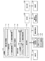
図1に、本実施形態の画像生成システム(ゲームシステム)の機能ブロック図の一例を示す。なお、本実施形態の画像生成システムは、図1の各部(機能ブロック)を全て含む必要はなく、その一部(例えば操作部160、携帯型情報記憶装置194又は通信部196等)を省略した構成としてもよい。
【0027】
操作部160は、プレーヤが操作データを入力するためのものであり、その機能は、レバー、ボタン、ステアリング、シフトレバー、アクセルペダル、ブレーキペダル、マイク、センサー、或いは筺体などのハードウェアにより実現できる。
【0028】
記憶部170は、処理部100や通信部196などのワーク領域となるもので、その機能はRAMなどのハードウェアにより実現できる。
【0029】
情報記憶媒体180(コンピュータにより読み取り可能な媒体)は、プログラムやデータなどを格納するものであり、その機能は、光ディスク(CD、DVD)、光磁気ディスク(MO)、磁気ディスク、ハードディスク、磁気テープ、或いはメモリ(ROM)などのハードウェアにより実現できる。処理部100は、この情報記憶媒体180に格納されるプログラム(データ)に基づいて本実施形態の種々の処理を行う。即ち情報記憶媒体180には、本実施形態の各部としてコンピュータを機能させるためのプログラム(各部をコンピュータに実現させるためのプログラム)が記憶(記録、格納)される。
【0030】
表示部190は、本実施形態により生成された画像を出力するものであり、その機能は、CRT、LCD、或いはHMD(ヘッドマウントディスプレイ)などのハードウェアにより実現できる。
【0031】
音出力部192は、本実施形態により生成された音を出力するものであり、その機能は、スピーカ、或いはヘッドフォンなどのハードウェアにより実現できる。
【0032】
携帯型情報記憶装置194は、プレーヤの個人データやゲームのセーブデータなどが記憶されるものであり、この携帯型情報記憶装置194としては、メモリカードや携帯型ゲーム装置などを考えることができる。
【0033】
通信部196は、外部(例えばホスト装置や他の画像生成システム)との間で通信を行うための各種の制御を行うものであり、その機能は、各種プロセッサ又は通信用ASICなどのハードウェアや、プログラムなどにより実現できる。
【0034】
なお本実施形態の各部としてコンピュータを機能させるためのプログラム(データ)は、ホスト装置(サーバー)が有する情報記憶媒体からネットワーク及び通信部196を介して情報記憶媒体180(記憶部170)に配信するようにしてもよい。このようなホスト装置(サーバー)の情報記憶媒体の使用も本発明の範囲内に含まれる。
【0035】
処理部100(プロセッサ)は、操作部160からの操作データやプログラムなどに基づいて、ゲーム処理、画像生成処理、或いは音生成処理などの各種の処理を行う。この場合、処理部100は、記憶部170内の主記憶部172をワーク領域として使用して、各種の処理を行う。この処理部100の機能は、各種プロセッサ(CPU、DSP等)又はASIC(ゲートアレイ等)などのハードウェアや、プログラム(ゲームプログラム)により実現できる。
【0036】
処理部100は、移動・動作処理部110、オブジェクト空間設定部112、仮想カメラ(視点)制御部118、画像生成部120、音生成部130を含む。なお、処理部100は、これらの各部(機能ブロック)を全て含む必要はなく、その一部を省略してもよい。
【0037】
移動・動作処理部110は、オブジェクト(移動オブジェクト)の移動情報(位置、回転角度)や動作情報(オブジェクトの各パーツの位置、回転角度)を求める処理を行う。即ち、操作部160によりプレーヤが入力した操作データやゲームプログラムなどに基づいて、オブジェクトを移動させたり動作(モーション、アニメーション)させたりする処理を行う。
【0038】
オブジェクト空間設定部112は、移動体(キャラクタ、車、戦車、ロボット)、柱、壁、建物、マップ(地形)などの各種オブジェクト(ポリゴン、自由曲面又はサブディビジョンサーフェスなどのプリミティブ面で構成されるオブジェクト)をオブジェクト空間内に配置設定するための処理を行う。より具体的には、ワールド座標系でのオブジェクトの位置や回転角度(方向)を決定し、その位置(X、Y、Z)にその回転角度(X、Y、Z軸回りでの回転)でオブジェクトを配置する。
【0039】
オブジェクト空間設定部112は仮想点設定部114を含む。この仮想点設定部114は、仮想カメラの視点位置とは別に用意される仮想点(プログラムにおいて、視点位置とは別のパラメータでその位置が表される仮想的な点)をオブジェクト空間に設定する。
【0040】
そして、オブジェクト空間設定部112は、設定された仮想点と各オブジェクト(例えば板形状のオブジェクト又は基準線から放射状に延びる複数のプリミティブ面を有するオブジェクト)との位置関係により決められる方向(例えばオブジェクトの任意の点と仮想点とを結ぶ線分の方向)と、各オブジェクトの向き(例えばオブジェクトのプリミティブ面又は主面の法線ベクトルの方向)とが、所定の方向関係(例えば平行)になるように、オブジェクト空間内にオブジェクトを配置設定する。
【0041】
オブジェクト空間設定部112は仮想方向設定部116を含む。この仮想方向設定部116は、オブジェクト(オブジェクト群)の向き(例えばオブジェクトのプリミティブ面又は主面の法線ベクトルの方向)を設定するための方向であり仮想カメラの視線方向とは別に用意される仮想方向(プログラムにおいて、視線方向とは別のパラメータでその方向が表される仮想的な方向)を、オブジェクト空間に設定する。
【0042】
そして、オブジェクト空間設定部112は、設定された仮想方向とオブジェクト(例えば板形状のオブジェクト又は基準線から放射状に延びる複数のプリミティブ面を有するオブジェクト)の向きとが、所定の方向関係(例えば平行)になるように、オブジェクト空間内にオブジェクト(オブジェクト群)を配置設定する。
【0043】
仮想カメラ制御部118は、オブジェクト空間内の所与(任意)の視点での画像を生成するための仮想カメラを制御する処理を行う。即ち、仮想カメラの位置(X、Y、Z)又は回転(X、Y、Z軸回りでの回転)を制御する処理(視点位置や視線方向を制御する処理)等を行う。
【0044】
例えば、仮想カメラにより移動オブジェクトを後方から撮影する場合には、移動オブジェクトの位置又は回転の変化に仮想カメラが追従するように、仮想カメラの位置又は回転(仮想カメラの方向)を制御する。この場合には、移動・動作演算部110で得られた移動オブジェクトの位置、方向又は速度などの情報に基づいて、仮想カメラを制御することになる。或いは、仮想カメラを、予め決められた移動経路で移動させながら予め決められた角度で回転させるようにしてもよい。この場合には、仮想カメラの位置(移動経路)や回転角度を特定するための仮想カメラデータに基づいて仮想カメラを制御することになる。
【0045】
画像生成部120は、処理部100で行われる種々の処理の結果に基づいて描画処理を行い、これにより画像を生成し、表示部190に出力する。即ち、いわゆる3次元のゲーム画像を生成する場合には、まず、座標変換、クリッピング処理、透視変換或いは光源処理等のジオメトリ処理が行われ、その処理結果に基づいて、描画データ(プリミティブ面の頂点の位置座標、テクスチャ座標、色データ、法線ベクトル或いはα値等)が作成される。そして、この描画データ(プリミティブ面データ)に基づいて、透視変換後(ジオメトリ処理後)のオブジェクト(1又は複数プリミティブ面)が、描画バッファ174(フレームバッファ、ワークバッファ等のピクセル単位で画像情報を記憶できるバッファ)に描画される。これにより、オブジェクト空間内において仮想カメラ(所与の視点)から見える画像が生成されるようになる。
【0046】
画像生成部120はα合成部122を含む。このα合成部122は、α値(A値)に基づくα合成処理(αブレンディング、α加算又はα減算等)を行う。例えばα合成がαブレンディングである場合には下式のような合成処理が行われる。
【0047】
RQ=(1−α)×R1+α×R2 (1)
GQ=(1−α)×G1+α×G2 (2)
BQ=(1−α)×B1+α×B2 (3)
ここで、R1、G1、B1は、描画バッファ174に既に描画されている画像(背景画像)の色(輝度)のR、G、B成分であり、R2、G2、B2は、描画バッファ174に描画するオブジェクト(プリミティブ)の色のR、G、B成分である。また、RQ、GQ、BQは、αブレンディングにより得られる画像の色のR、G、B成分である。
【0048】
なお、α値(A値)は、各ピクセル(テクセル、ドット)に関連づけて記憶できる情報であり、例えば色情報以外のプラスアルファの情報である。α値は、マスク情報、半透明度(透明度、不透明度と等価)、バンプ情報などとして使用できる。
【0049】
画像生成部120はデプスキューイング部124を含む。このデプスキューイング部124は、オブジェクトのデプスキューイング処理を行う。
【0050】
ここでデプスキューイング処理は、オブジェクトの色(輝度)を距離を関数として補間して、背景の色(広義にはターゲット色)に徐々に近づける処理である。例えば背景色が青であった場合には、距離(例えば仮想カメラ又は仮想点からの距離)が遠いオブジェクトほど、その色が青に近づくようになる。従って、オブジェクトの元の色が何色であっても、遠景においてはオブジェクトの色が背景色に近づき、オブジェクトが背景に溶け込んだかのように見える画像を生成できる。なお、デプスキューイング処理は、デプスキューイング効果の強さを決めるパラメータであるデプスキューイング値を用いて制御される。
【0051】
画像生成部120はテクスチャマッピング部126を含む。このテクスチャマッピング部126は、テクスチャ記憶部176に記憶されるテクスチャをオブジェクトにマッピングする処理を行う。具体的には、オブジェクト(プリミティブ面)の頂点に設定(付与)されるテクスチャ座標等を用いて、テクスチャ記憶部176からテクスチャ(色、輝度、法線、α値などの表面プロパティ)を読み出す。そして、2次元の画像又はパターンであるテクスチャをオブジェクトにマッピング(project)する。この場合に、画素とテクセルとを対応づける処理やバイリニア補間(テクセル補間)などを行う。また、インデックスカラー・テクスチャマッピング用のLUT(ルックアップテーブル)を用いたテクスチャマッピングを行うようにしてもよい。
【0052】
画像生成部120は画像処理変更部128を含む。この画像処理変更部128は、オブジェクトと仮想点との距離(奥行き距離、直線距離等)に応じて、オブジェクトに施される画像処理の内容を変更する。
【0053】
より具体的には、オブジェクトと仮想点との距離に基づいて、α合成処理、デプスキューイング処理、テクスチャマッピング処理が行われるようにする。例えば、オブジェクトと仮想点との距離に基づいて、オブジェクトに使用されるα値(半透明度、透明度)を変更する。或いは、オブジェクトと仮想点の距離に基づいて、デプスキューイング処理が行われるようにする。或いは、オブジェクトと仮想点の距離に基づいて、オブジェクトにマッピングされるテクスチャ(テクスチャ座標)を変更する。
【0054】
音生成部130は、処理部100で行われる種々の処理の結果に基づいて音処理を行い、BGM、効果音、又は音声などのゲーム音を生成し、音出力部192に出力する。
【0055】
なお、本実施形態の画像生成システムは、1人のプレーヤのみがプレイできるシングルプレーヤモード専用のシステムにしてもよいし、このようなシングルプレーヤモードのみならず、複数のプレーヤがプレイできるマルチプレーヤモードも備えるシステムにしてもよい。
【0056】
また複数のプレーヤがプレイする場合に、これらの複数のプレーヤに提供するゲーム画像やゲーム音を、1つの端末を用いて生成してもよいし、ネットワーク(伝送ライン、通信回線)などで接続された複数の端末(ゲーム機、携帯電話)を用いて生成してもよい。
【0057】
2.本実施形態の手法
次に本実施形態の手法について図面を用いて説明する。
【0058】
2.1 仮想点の設定
さて、いわゆるビルボード処理では、図2(A)に示すように、仮想カメラVCの視点位置VWPとオブジェクトOB1、OB2、OB3を結ぶ方向を求める。そして、求められた方向とOB1、OB2、OB3の向きN1、N2、N3とが平行になるように、OB1、OB2、OB3を配置する。これにより、オブジェクトOB1〜OB3が仮想カメラVCの視点位置VWPの方に正対するように配置される。
【0059】
しかしながら、これまでのビルボード処理では、オブジェクトOB1〜OB3の向きを決定するのに、仮想カメラの視点位置だけが用いられていた。このため、生成される画像が画一的になってしまったり、オブジェクト配置の設計の自由度が制限されてしまうなどの課題があることが判明した。
【0060】
そこで本実施形態では図2(B)に示すように、仮想カメラVCの視点位置VWPとは別に仮想点VLPを用意する。即ち、視点位置VWPのパラメータとは別のパラメータ(変数)でその位置が表される仮想点VLPを用意する。
【0061】
そして、この仮想点VLPとオブジェクトOB1〜OB3との位置関係により決められる方向と、OB1〜OB3の向きN1〜N3とが所定(所与)の方向関係になるように、OB1〜OB3を配置する。
【0062】
このようにすることで、図2(A)では、仮想カメラVCの視点位置VWPの方にしかオブジェクトOB1〜OB3を正対させることができなかったのに対して、図2(B)では、仮想点VLPの方にオブジェクトOB1〜OB3を正対させることが可能になる。これにより、視点位置VWPとは独立に任意の位置に設定可能な仮想点VLPの方に、オブジェクトOB1〜OB3を向かせることが可能になる。従って、視点設定の変更イベントの発生、仮想カメラVCが追従するオブジェクトとVCとの位置関係、或いはゲーム状況の変化などに応じて、種々の位置に仮想点VLPを設定することで、多種多様な画像を生成できるようになる。また、仮想点VLPを任意の位置に設定することで、オブジェクト配置の設計の自由度を増すことが可能になり、ゲーム設計の容易化を図れる。
【0063】
なお、VLPとOB1〜OB3との位置関係(位置座標)により決められる方向は、例えば、VLPとOB1〜OB3の任意の点(代表点又は頂点等)とを結ぶ方向である。或いは、VLPの第1、第2の座標成分(X、Z座標)で特定される点(XZ平面上の点)と、OB1〜OB3の第1、第2の座標成分で特定される点とを結ぶ方向などであってもよい。
【0064】
また、オブジェクトOB1〜OB3の向きN1〜N3(表示方向の向き。表の面の向き)は、オブジェクトOB1〜OB3を構成するプリミティブ面(主面)の法線ベクトルの方向である。或いは、オブジェクトOB1〜OB3の向きを代表的に表す方向として仮想的に設定された方向であってもよい。
【0065】
また、VLPとOB1〜OB3との位置関係により決められる方向とOB1〜OB3の向きN1〜N3とが所定の方向関係になるとは、例えば、その方向とN1〜N3とのなす角度が所定の角度になることである。より具体的には図2(B)に示すように、その方向とN1〜N3とのなす角度を例えば零度(ほぼ零度の場合を含む)に設定して、その方向とN1〜N3が平行(ほぼ平行の場合を含む)になるようにする。
【0066】
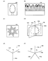
図3(A)〜(F)に、仮想点VLP(或いは仮想方向)に基づいてその向きが設定されるオブジェクトOB(図2(B)のOB1〜OB3)の例を示す。
【0067】
図3(A)のOBは板形状のオブジェクト(1又は複数のプリミティブ面を平面的に配置することで構成されるオブジェクト)であり、木の画像(立体的に見えるようにCGにより作成された画像)がOBに描かれている。より具体的には木の画像のテクスチャ(木が描かれている部分以外は透明のテクスチャ)がOBにマッピングされている。
【0068】
図3(A)の板形状のオブジェクトOBを多数配置することで森林を表現できる。そして、仮想点VLPの方にその向きが向くように複数のオブジェクトOBを配置すれば、より少ない個数のオブジェクトOBで、より広い面積を占める森林を表現できる。
【0069】
図3(B)、(C)のOBも板形状のオブジェクトであり、観客の画像、爆発の画像がOBに描かれている。より具体的には観客の画像、爆発の画像のテクスチャがOBにマッピングされている。図3(B)、(C)の板形状のオブジェクトOBを多数配置することで、大きな観客席や大きな爆発を表現できる。
【0070】
なお、図3(A)、(B)、(C)のオブジェクトOBでは、画像が描かれている表示面側(表の面)の法線ベクトルの方向を、OBの向き(図2(B)のN1〜N3)に設定できる。
【0071】
図3(D)、(E)、(F)のOBは、基準線RL(中心線)から放射状に延びる複数のプリミティブ面(ポリゴン)PR1〜PR4、PR1〜PR3、PR1〜PR5を有するオブジェクトである。図3(D)、(E)、(F)に示すようなオブジェクトOBを用いれば、いわゆる書き割り形状(十字形状等)であるのにもかかわらず、あたかもボリュームを持つ立体形状であるかのように表示物を見せることができる。
【0072】
なお、図3(D)、(E)、(F)のオブジェクトOBでは、OBを構成するプリミティブ面のうちの1つのプリミティブ面(PR1〜PR5のいずれか)の法線ベクトルの方向を、OBの向き(図2(B)のN1〜N3)に設定できる。或いは、オブジェクトOBに仮想的に設定された代表方向を、OBの向きに設定してもよい。この場合の代表方向としては、例えば、プリミティブ面(PR1〜PR5のいずれか)に沿った方向や、第1のプリミティブ面(例えばPR1)に沿った方向と第2のプリミティブ面(例えばPR2)に沿った方向の中間方向などを採用できる。
【0073】
また、図3(D)、(E)、(F)のオブジェクトOBにおいて、プリミティブ面PR1〜PR5に交差(直交)するプリミティブ面を更に付加してもよい。
【0074】
また、図3(A)〜(F)のオブジェクトOBに、ムービー・テクスチャをマッピングするようにしてもよい。
【0075】
2.2 注視点、移動体位置への仮想点の設定
仮想点VLPを設定位置としては種々の位置を考えることができる。
【0076】
例えば図4では、オブジェクトOB1、OB2がゲームにおいて注視する点の位置に、VLPが設定されている。
【0077】
より具体的には、オブジェクトOB1、OB2には、図3(B)に示すような観客の画像がマッピングされている。そして、ゲームにおける観客の注視点は、オブジェクトEOB1、EOB2(他のプレーヤ又はコンピュータが操作するオブジェクト)のクラッシュ地点になっている。この場合には、OB1、OB2の注視点であるクラッシュ地点に、仮想点VLPを設定する。なお、MOBは仮想カメラVCが追従するオブジェクト(プレーヤが操作するオブジェクト)である。
【0078】
図4のようにすれば、観客表現用のオブジェクトOB1、OB2の向きN1、N2が、仮想点VLPが設定される注視点(クラッシュ地点)の方に向くようになる。従って、観客がクラッシュ地点を注視している様子が、仮想カメラVCから見えるようになり、より多様でリアルな画像を表現できる。例えば図2(A)のように視点位置VWPだけに基づいてオブジェクトの向きを設定する手法では、図4に示すような画像表現を実現できない。
【0079】
なお、仮想点VLPが設定される注視点は、固定的な位置であってもよいし、ゲーム状況、ゲーム進行、時間経過又移動オブジェクトの速度等に応じてその位置を動的に変化させてもよい。
【0080】
また、仮想点VLPが設定される注視点としては、ゲームにおけるイベントの発生位置(クラッシュ位置、キャラクタ同士の戦闘位置)、球技ゲームにおけるボールの位置など、種々のものを考えることができる。
【0081】
図5(A)では、仮想カメラVCが追従する移動オブジェクトMOB(プレーヤが操作するオブジェクト)の位置(代表点)に、仮想点VLPが設定されている。
【0082】
図5(A)のようにすれば、オブジェクトOB1〜OB3の向きN1、N2、N3が、仮想点VLPが設定された移動オブジェクトMOBの方に向くようになる。従って、仮想カメラVCの視点位置VWPの変化に依らず、オブジェクトOB1〜OB3の向きN1〜N3が、移動オブジェクトMOBを注視する方向に向くようになる。
【0083】
また図5(B)、(C)では、仮想カメラVCが追従する移動オブジェクトMOBの速度により決められる位置に、仮想点VLPが設定されている。
【0084】
例えば図5(B)では、移動オブジェクトMOBの速度が速いため、オブジェクトOB1〜OB3から、より近い位置に仮想点VLPが設定される。一方、図5(C)では、移動オブジェクトMOBの速度が遅いため、オブジェクトOB1〜OB3から、より遠い位置に仮想点VLPが設定される。
【0085】
このようにすれば、移動オブジェクトMOBの速度が速いほど、図5(B)のオブジェクトOB1、OB3の向きN1、N3が、MOBの移動方向(仮想カメラVCの視線方向VWD)に対してより直交する方向に向くようになる。この結果、スピード感溢れる画像が仮想カメラVCから見えるようになり、画像のリアル度を増すことができる。
【0086】
なお、移動オブジェクトMOBの速度に応じて仮想点VLPの位置を変化させる場合には、仮想カメラVCの視線方向VWDの線分上で、MOBの速度に応じて仮想点VLPの位置を変化させてもよい。或いは、移動オブジェクトMOBが走行するコースに沿った方向(コースデータが有するコース方向データにより特定される方向)の線分上で、MOBの速度に応じて仮想点VLPの位置を変化させてもよい。
【0087】
2.3 オブジェクト群毎の仮想点の設定
本実施形態では、オブジェクト群毎に異なる仮想点を設定できる。
【0088】
例えば図6では、オブジェクトOB1〜OB3(第1のオブジェクト群)は、仮想点VLP1(第1の仮想点)に基づいて、その向きN1〜N3が設定される。即ち、仮想点VLP1とOB1〜OB3との位置関係により決められる方向とOB1〜OB3の向きN1〜N3とが、所定(所与)の方向関係になるように、OB1〜OB3が配置される。なお、仮想点VLP1の代わりに、仮想カメラVCの視点位置VWPに基づいて、OB1〜OB3の向きN1〜N3を設定してもよい。
【0089】
一方、オブジェクトOB4〜OB6(第2のオブジェクト群)は、仮想点VLP2(第2の仮想点)に基づいて、その向きN4〜N6が設定される。即ち、仮想点VLP2とOB4〜OB6との位置関係により決められる方向とOB4〜OB6の向きN4〜N6とが、所定の方向関係になるように、OB4〜OB6が配置される。
【0090】
このように、オブジェクト群毎に異なる仮想点を設定することで、更に多様な画像を生成できる。
【0091】
例えば、オブジェクトOB1〜OB3として図3(B)に示すような観客表現用オブジェクトを採用し、これらのOB1〜OB3については、OB1〜OB3から近い位置に設定される仮想点VLP1(或いは視点位置VWP)に基づいて、その向きN1〜N3を設定する。
【0092】
一方、オブジェクトOB4〜OB7として図3(A)に示すような木表現用のオブジェクトを採用し、これらのOB4〜OB7については、OB4〜OB7から遠い位置に設定される仮想点VLP2に基づいて、その向きN4〜N6を設定する。
【0093】
このようにすれば、観客表現用のオブジェクトOB1、OB3の向きN1、N3を、仮想カメラVCの視線方向VWDに対してより直交する方向に向けることが可能になる。これにより、観客がVLP1の方を注視している様子を表現できる。
【0094】
一方、木表現用のオブジェクトOB4、OB6の向きN4、N6については、仮想カメラVCの視線方向VWDに対してより平行な方向に向けることが可能になる。これにより、より少ない個数のオブジェクトで、より広い面積を占める森林を表現できるようになる。
【0095】
なお、仮想点VLP1、VLP2は、仮想カメラVCの視線方向VWDの線分上(視点位置VWPを通る線分上)において異なった位置に設定できる。或いは、移動オブジェクトが走行するコースに沿った方向(コースデータが有するコース方向データにより特定される方向)の線分上で、異なった位置に設定してもよい。
【0096】
また、仮想カメラVCの視点設定の変更イベント(広義には、ゲーム中のイベント)が発生したことを条件に、オブジェクト群毎に異なる仮想点を設定するようにしてもよい。
【0097】
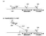
例えば図7(A)に示すように、視点設定変更イベントの発生前においては、爆発表現用の第1のオブジェクト群のオブジェクトOB1、木表現用の第2のオブジェクト群のオブジェクトOB2は、共に、仮想カメラVCの視点位置VWP(或いは視線方向VWD)に基づいて、その向きN1、N2が設定されている。
【0098】
一方、図7(B)に示すように、仮想カメラVCの視点位置VWPや視線方向VWDが急激に変化する視点設定変更イベントが発生した場合には、仮想点VLP1、VLP2を新たに設定する(VLP1、VLP2のパラメータを用意する)。そして、爆発表現用の第1のオブジェクト群のオブジェクトOB1については、仮想点VLP1又は視点位置VWPに基づいて、その向きN1を設定する。一方、木表現用の第2のオブジェクト群のオブジェクトOB2については、仮想点VLP2に基づいて、その向きN2を設定する。即ち、オブジェクト毎の仮想点の設定を異ならせる。
【0099】
このようにすることで、例えば、爆発表現用の第1のオブジェクト群のオブジェクトOB1の向きN1については、仮想点VLP1(視点位置VWP)の方に向き、木表現用の第2のオブジェクト群のオブジェクトOB2の向きN2については、仮想点VLP2の方に向くという、オブジェクトの配置制御が可能になる。
【0100】
これにより、視点設定変更イベントの発生により、木表現用のオブジェクトOB2の向きN2が仮想カメラVCの方に向いてしまうというような不自然な画像が生成されるのを防止できる。一方、爆発表現用のオブジェクトOB1については、視点設定変更イベントの発生時に仮想カメラVCの方に向いても不自然な画像にならない。逆にOB1の向きN1を仮想カメラVCの方に向けることで、VCから見たときのスクリーン上での爆発表示の占有面積が増すという利点が得られる。
【0101】
なお、視点設定変更イベントは、仮想カメラの視点位置や視線方向が急激に変化等することで、仮想カメラの制御プログラムのアルゴリズムの切り替えが必要になるイベント等である。例えば、コース上で走行する移動オブジェクトに仮想カメラが追従している時に、仮想カメラが急激に上空に移動するイベントや、移動オブジェクトがスリップしてその向きが急激に変化するイベントや、ロールプレイングゲームにおいてゲーム場面が切り替わるイベントなどを考えることができる。
【0102】
2.4 仮想点から距離に応じた画像処理内容の変更
本実施形態によれば、オブジェクトと仮想点との距離に応じて、オブジェクトに施される画像処理の内容を変更できる。より具体的には、オブジェクトと仮想点との距離に基づいて、オブジェクトのα値(半透明度、透明度)の変更処理、デプスキューイング処理、テクスチャ(テクスチャ座標)の変更処理などを行う。
【0103】
例えば図8(A)において、オブジェクトOB1、OB2、OB3にはフォグ(霧、雲又は煙等)の画像(テクスチャ)が描かれている。そして、仮想点VLPとオブジェクトOB1、OB2、OB3の間の距離(奥行き距離或いは直線距離等)はD1、D2、D3(D1<D2<D3)となっている。
【0104】
この場合に本実施形態では、例えば仮想点VLPから遠いオブジェクトほど、より不透明になるようにα値を設定する。例えば図8(A)では、オブジェクトOB1、OB2、OB3の順で、徐々に不透明度が高くなっている。このようにすることで、手前側では半透明で、奥側に行くほど徐々に不透明になってゆくリアルなフォグ画像を表現できる。
【0105】
また図8(B)において、オブジェクトOB1、OB2、OB3にはビル、看板、道路等の画像(テクスチャ)が描かれている。そして、仮想点VLPとオブジェクトOB1、OB2、OB3の間の距離はD1、D2、D3(D1<D2<D3)となっている。
【0106】
この場合に本実施形態では、例えば仮想点VLPから遠いオブジェクトほど、よりデプスキューイング効果(背景色の補間率)が高くなるように設定する。例えば図8(B)では、オブジェクトOB1、OB2、OB3の順で、その色が、徐々に背景色(ターゲット色)に近づいて行く。このようにすることで、奥側のオブジェクトが背景に溶け込んで行く様子を表現できる。
【0107】
また図8(C)において、仮想点VLPとオブジェクトOB1、OB2、OB3の間の距離はD1、D2、D3(D1<D2<D3)となっている。
【0108】
この場合に本実施形態では、仮想点VLPとオブジェクトの間の距離に応じて、そのオブジェクトにマッピングされるテクスチャを変更する。これにより、距離に応じて、オブジェクトの絵柄や半透明度を変化させることが可能になる。
【0109】
例えば本実施形態と異なる手法として、仮想カメラVCの視点位置VWPからの距離に応じて、オブジェクトに施す画像処理の内容を変化させる手法を考えることができる。
【0110】
しかしながら、この手法では、α合成処理のα値やデプスキューイング処理の補間率を制御するパラメータとして、視点位置VWPからの距離だけしか用いることができない。このため、α値や補間率を求める関数(距離を引数とする関数)が複雑化するなどの問題が生じる。
【0111】
これに対して、本実施形態のように仮想点VLPからの距離に基づいてα値や補間率を制御する手法によれば、仮想点VLPを適切な位置に設定することで、α値や補間率を求める関数の簡素化等を図れる。例えば、オブジェクトOB1〜OB3のうち、奥側に位置するOB2、OB3だけについて、そのα値や補間率を変化させたい場合には、OB2の手前の位置に仮想点VLPを設定する。そして、オブジェクトOB2、OB3と仮想点VLPとの距離を引数となる簡素な関数(例えば一次関数、2次関数等)を用いて、OB2、OB3のα値や補間率を求めるようにする。
【0112】
なお、仮想点との距離に応じて変更する画像処理は、図8(A)、(B)、(C)に限定されず、種々の処理を考えることができる。また、2個以上の仮想点を用いて画像処理の内容を変更してもよい。また、オブジェクトの向き等を変更せずに、仮想点との距離に応じて画像処理の内容だけを変更するようにしてもよい。
【0113】
2.5 仮想方向の設定
以上では、仮想点を用いてオブジェクトの向きを制御していたが、本実施形態では、仮想方向を用いてオブジェクトの向きを制御することもできる。
【0114】
具体的には図9(A)に示すように、複数のオブジェクトOB1〜OB3の向きN1、N2、N3を一律に設定するための仮想方向VLDを用意する。この仮想方向VLDは、仮想カメラVCの視線方向VWDとは別に用意される。即ち、仮想方向VLDは、視線方向VWDのパラメータとは別のパラメータ(変数)でその方向が表される。なお、一時的に仮想方向VLDと視線方向VWDが同じ方向になってもかまわない。
【0115】
そして本実施形態では図9(A)に示すように、仮想方向VLDとオブジェクトOB1〜OB3(図3(A)〜(F)のオブジェクト)の向きN1〜N3とが所定(所与)の方向関係になるように、OB1〜OB3を配置する。
【0116】
このようにすれば、仮想カメラVCの視線方向VWDとは独立に任意の方向に設定可能な仮想方向VLDを用いて、オブジェクトOB1〜OB3の向きN1〜N3を制御できるようになる。従って、オブジェクトOB1〜OB3の向きN1〜N3を視線方向VWDでしか制御できない手法に比べて、オブジェクト配置の設計の自由度を増すことができる。また、仮想方向VLDを任意の方向に設定することで、多種多様な画像を生成できるようになる。
【0117】
例えば本実施形態によれば、図9(B)に示すように仮想カメラVCの視線方向VWDが変化した場合にも、この変化に仮想方向VLDを追従させないようにすることができる。従って、視線方向VWDが変化した時にも、オブジェクトOB1〜OB3の向きN1〜N4は変化しないようになり、より自然な画像を生成できる。
【0118】
また、図2(B)に示す仮想点VLPを用いる手法では、VLPとオブジェクトOB1〜OB3とを結ぶ線分を求める処理が必要になる。これに対して、仮想方向VLDを用いる手法によれば、このような処理が不要になり、処理負荷を軽減できる。
【0119】
なお、仮想方向VLDとOB1〜OB3の向きN1〜N3とが所定の方向関係になるとは、例えば、VLDとN1〜N3とのなす角度が所定の角度になることである。より具体的には図9(A)、(B)に示すように、仮想方向VLDとN1〜N3とのなす角度を例えば零度(ほぼ零度の場合を含む)に設定して、仮想方向VLDとN1〜N3が平行(ほぼ平行の場合を含む)になるようにする。或いは、仮想方向VLDのベクトルの第1、第2の座標成分(X、Z座標)で決められる方向と、N1〜N3のベクトルの第1、第2の座標成分で決められる方向とのなす角度が、所定の角度になるように、オブジェクトOB1〜OB3を配置してもよい。
【0120】
2.6 オブジェクト群毎の仮想点の設定
本実施形態では、オブジェクト群毎に異なる仮想方向を設定できる。
【0121】
例えば図10において、オブジェクトOB1〜OB3(第1のオブジェクト群)については仮想方向VLD1(第1の仮想方向)に基づいて、その向きN1〜N3を設定し、オブジェクトOB4〜OB6(第2のオブジェクト群)については、仮想方向VLD2(第2の仮想方向)に基づいて、その向きN4〜N6を設定する またオブジェクトOB7〜OB9(第3のオブジェクト群)については、仮想方向VLD3(第3の仮想方向)に基づいて、その向きN7〜N9を設定する。なお、仮想方向VLD1の代わりに、仮想カメラVCの視線方向VWDに基づいて、OB1〜OB3の向きN1〜N3を設定してもよい。
【0122】
このように、オブジェクト群毎に異なる仮想方向を設定することで、更に多様な画像を生成できるようになる。
【0123】
例えば、オブジェクトOB1〜OB3として図3(A)に示すような木表現用のオブジェクトを採用し、これらのOB1〜OB3については、視線方向VWDと同じ又は近い方向に設定される仮想方向VLD1(或いはVWDそのもの)に基づいて、その向きN1〜N3を設定する。
【0124】
一方、オブジェクトOB4〜OB6、OB7〜OB9として図3(B)に示すような観客表現用のオブジェクトを採用し、これらのOB4〜OB6、OB7〜OB9については、視線方向VWDとは異なる方向に設定される仮想方向VLD2、VLD3に基づいて、その向きN4〜N6、N7〜N9を設定する。
【0125】
このようにすれば、木表現用のオブジェクトOB1〜OB3の向きN1〜N3を、視線方向VWDに対してより平行な方向に向けることが可能になる。これにより、少ない個数のオブジェクトで、より広い面積を占める森林を表現できる。
【0126】
一方、観客表現用オブジェクトOB4〜OB6、OB7〜OB9の向きN4〜N6、N7〜N9については、視線方向VWDに対してより直交する方向に向けることが可能になる。これにより、観客が移動オブジェクトや仮想カメラの方を注視している様子を表現できる。
【0127】
また、仮想カメラVCの視点設定の変更イベント(広義には、ゲーム中のイベント)が発生したことを条件に、オブジェクト群毎に異なる仮想方向を設定するようにしてもよい。
【0128】
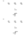
例えば図11(A)に示すように、視点設定変更イベントの発生前においては、爆発表現用の第1のオブジェクト群のオブジェクトOB1、木表現用の第2のオブジェクト群のオブジェクトOB2は、共に、仮想カメラVCの視線方向VWDに基づいて、その向きN1、N2が設定されている。
【0129】
一方、図11(B)に示すように、仮想カメラVCの視点位置VWPや視線方向VWDが急激に変化する視点設定変更イベントが発生した場合には、仮想方向VLD1、VLD2を新たに設定する(VLD1、VLD2のパラメータを用意する)。そして、爆発表現用の第1のオブジェクト群のオブジェクトOB1については、仮想方向VLD1又は視線方向VWDに基づいて、その向きN1を設定する。一方、木表現用の第2のオブジェクト群のオブジェクトOB2については、仮想方向VLD2に基づいて、その向きN2を設定する。即ち、オブジェクト毎の仮想方向の設定を異ならせる。
【0130】
このようにすることで、視点設定変更イベントの発生により、木表現用のオブジェクトOB2の向きN2が仮想カメラVCの方に向いてしまうというような不自然な画像が生成されるのを防止できる。一方、爆発表現用のオブジェクトOB1については、視点設定変更イベントの発生時に仮想カメラVCの方に向いても不自然な画像にならない。逆にOB1の向きN1を仮想カメラVCの方に向けることで、VCから見たときのスクリーン上での爆発表示の占有面積が増すという利点が得られる。
【0131】
2.7 移動オブジェクトとの位置関係に基づく仮想方向の設定
本実施形態では、仮想カメラと移動オブジェクトとの位置関係に基づき、仮想方向を設定できる。
【0132】
例えば図12(A)において、仮想カメラVCは移動オブジェクトMOBの移動に追従する。この時に、仮想カメラVCと移動オブジェクトMOBとの位置関係に基づいて、仮想方向VLDを設定する。
【0133】
ここで、仮想カメラVCと移動オブジェクトMOBとの位置関係に基づいて仮想方向VLDを設定するとは、例えば、仮想カメラVC(視点位置VWP)と移動オブジェクトMOB(代表点MP)とを結ぶ線分の方向を、仮想方向VLPに設定することである。或いは、視点位置VWPの第1、第2の座標成分(X、Z座標)で特定される点と、移動オブジェクトMOBの代表点MPの第1、第2の座標成分で特定される点を結ぶ線分の方向を、仮想方向VLPに設定してもよい。
【0134】
このようにすれば、例えば仮想カメラVCの視線方向VWDが変化した場合にも、仮想方向VLDは、移動オブジェクトMOBと仮想カメラVCを結ぶ線分の方向に常に向くようになる。この結果、視線方向VWDが変化した場合にも、オブジェクトOB1〜OB3の向きN1〜N3は、VLDに平行な方向に常に向くようになり、視線方向VWDの変化の影響を受けにくい自然な画像を生成できる。
【0135】
2.8 視線方向の変化への不追従
本実施形態では、仮想方向を、視線方向の変化に追従させない或いは弱い追従度で追従させるようにしてもよい。
【0136】
例えば図13(A)、(B)、(C)に示すように、仮想カメラVCの視線方向VWDが変化した場合にも、この変化に仮想方向VLDを追従させないようにする(或いは弱い追従度で追従させる)。このようにすれば、視線方向VWDが変化した場合にも、オブジェクトOB1〜OB3の向きN1〜N3は変化しないようになり、より自然な画像を生成できる。
【0137】
例えば、移動オブジェクト(車)のスリップ等が原因となって仮想カメラVCの視線方向VWDが急激に変化した場合に、この変化に追従してオブジェクトOB1〜OB3の向きN1〜N3が変化してしまうと、プレーヤが不自然さを感じてしまう可能性がある。
【0138】
図13(A)、(B)、(C)の手法によれば、オブジェクトOB1〜OB3の向きN1〜N3は、仮想方向VLD(VWDの初期方向)に基づき決められる。従って、移動オブジェクトのスリップ等により視線方向VWDが急激に変化した場合にも、N1〜N3の方向は変化しないようになり、自然な画像を生成できる。
【0139】
なお、 仮想方向VLDを弱い追従度で視線方向VWDに追従させる場合には、VWDの方向の変化を所与の減衰関数で減衰させ、減衰により得られた方向に、仮想方向VLDを設定すればよい。
【0140】
3.本実施形態の処理
次に、本実施形態の処理の詳細例について、図14、図15のフローチャートを用いて説明する。
【0141】
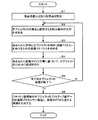
図14は仮想点を用いる手法の処理を示すフローチャートである。
【0142】
まず、視点位置とは別に仮想点を設定する(ステップS1)。即ち、プログラムにおいて仮想点のパラメータを宣言する。
【0143】
次に、オブジェクトの代表点(任意の点)と仮想点とを結ぶ線分の方向を求める(ステップS2)。そして、求められた方向にオブジェクトの向き(法線ベクトル)を向けるための変換マトリクス(例えばローカル座標系からワールド座標系への変換マトリクス)を求める(ステップS3)。
【0144】
次に、求められた変換マトリクス等に基づいて、オブジェクトのジオメトリ処理(座標系変換処理)を行う(ステップS4)。そして、全てのオブジェクトの処理が終了したか否かを判断し(ステップS5)、終了していない場合にはステップS2に戻る。
【0145】
全てのオブジェクトの処理が終了した場合には、ジオメトリ処理後のオブジェクトのプリミティブ面データ(ポリゴンデータ、頂点リスト)を作成し、描画プロセッサに転送する(ステップS6)。これにより、オブジェクト空間において仮想カメラから見える画像が生成されるようになる。
【0146】
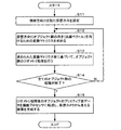
図15は仮想方向を用いる手法の処理を示すフローチャートである。
【0147】
まず、仮想カメラの視線方向とは別に仮想方向を設定する(ステップS11)。即ち、プログラムにおいて仮想方向のパラメータを宣言する。
【0148】
次に、設定された仮想方向にオブジェクト群の向きを向けるための変換マトリクスを求める(ステップS12)。
【0149】
次に、求められた変換マトリクス等に基づいて、オブジェクト群のジオメトリ処理を行う(ステップS13)。そして、全てのオブジェクトの処理が終了したか否かを判断し(ステップS14)、終了していない場合にはステップS12に戻る。
【0150】
全てのオブジェクトの処理が終了した場合には、ジオメトリ処理後のオブジェクトのプリミティブ面データを作成し、描画プロセッサに転送する(ステップS15)。これにより、オブジェクト空間において仮想カメラから見える画像が生成されるようになる。
【0151】
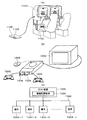
4.ハードウェア構成
次に、本実施形態を実現できるハードウェアの構成の一例について図16を用いて説明する。
【0152】
メインプロセッサ900は、CD982(情報記憶媒体)に格納されたプログラム、通信インターフェース990を介して転送されたプログラム、或いはROM950(情報記憶媒体の1つ)に格納されたプログラムなどに基づき動作し、ゲーム処理、画像処理、音処理などの種々の処理を実行する。
【0153】
コプロセッサ902は、メインプロセッサ900の処理を補助するものであり、高速並列演算が可能な積和算器や除算器を有し、マトリクス演算(ベクトル演算)を高速に実行する。例えば、オブジェクトを移動させたり動作(モーション)させるための物理シミュレーションに、マトリクス演算などの処理が必要な場合には、メインプロセッサ900上で動作するプログラムが、その処理をコプロセッサ902に指示(依頼)する。
【0154】
ジオメトリプロセッサ904は、座標変換、透視変換、光源計算、曲面生成などのジオメトリ処理を行うものであり、高速並列演算が可能な積和算器や除算器を有し、マトリクス演算(ベクトル演算)を高速に実行する。例えば、座標変換、透視変換、光源計算などの処理を行う場合には、メインプロセッサ900で動作するプログラムが、その処理をジオメトリプロセッサ904に指示する。
【0155】
データ伸張プロセッサ906は、圧縮された画像データや音データを伸張するデコード処理を行ったり、メインプロセッサ900のデコード処理をアクセレートする処理を行う。これにより、オープニング画面、インターミッション画面、エンディング画面、或いはゲーム画面などにおいて、MPEG方式等で圧縮された動画像を表示できるようになる。なお、デコード処理の対象となる画像データや音データは、ROM950、CD982に格納されたり、或いは通信インターフェース990を介して外部から転送される。
【0156】
描画プロセッサ910は、ポリゴンや曲面などのプリミティブ(プリミティブ面)で構成されるオブジェクトの描画(レンダリング)処理を高速に実行するものである。オブジェクトの描画の際には、メインプロセッサ900は、DMAコントローラ970の機能を利用して、オブジェクトデータを描画プロセッサ910に渡すと共に、必要であればテクスチャ記憶部924にテクスチャを転送する。すると、描画プロセッサ910は、これらのオブジェクトデータやテクスチャに基づいて、Zバッファなどを利用した隠面消去を行いながら、オブジェクトをフレームバッファ922に高速に描画する。また、描画プロセッサ910は、αブレンディング(半透明処理)、デプスキューイング、ミップマッピング、フォグ処理、バイリニア・フィルタリング、トライリニア・フィルタリング、アンチエリアシング、シェーディング処理なども行うことができる。そして、1フレーム分の画像がフレームバッファ922に書き込まれると、その画像はディスプレイ912に表示される。
【0157】
サウンドプロセッサ930は、多チャンネルのADPCM音源などを内蔵し、BGM、効果音、音声などの高品位のゲーム音を生成する。生成されたゲーム音は、スピーカ932から出力される。
【0158】
ゲームコントローラ942(レバー、ボタン、筺体、パッド型コントローラ又はガン型コントローラ等)からの操作データや、メモリカード944からのセーブデータ、個人データは、シリアルインターフェース940を介してデータ転送される。
【0159】
ROM950にはシステムプログラムなどが格納される。なお、業務用ゲームシステムの場合には、ROM950が情報記憶媒体として機能し、ROM950に各種プログラムが格納されることになる。なお、ROM950の代わりにハードディスクを利用するようにしてもよい。
【0160】
RAM960は、各種プロセッサの作業領域として用いられる。
【0161】
DMAコントローラ970は、プロセッサ、メモリ(RAM、VRAM、ROM等)間でのDMA転送を制御するものである。
【0162】
CDドライブ980は、プログラム、画像データ、或いは音データなどが格納されるCD982(情報記憶媒体)を駆動し、これらのプログラム、データへのアクセスを可能にする。
【0163】
通信インターフェース990は、ネットワークを介して外部との間でデータ転送を行うためのインターフェースである。この場合に、通信インターフェース990に接続されるネットワークとしては、通信回線(アナログ電話回線、ISDN)、高速シリアルバスなどを考えることができる。そして、通信回線を利用することでインターネットを介したデータ転送が可能になる。また、高速シリアルバスを利用することで、他の画像生成システムとの間でのデータ転送が可能になる。
【0164】
なお、本実施形態の各部(各手段)は、その全てを、ハードウェアのみにより実現してもよいし、情報記憶媒体に格納されるプログラムや通信インターフェースを介して配信されるプログラムのみにより実現してもよい。或いは、ハードウェアとプログラムの両方により実現してもよい。
【0165】
そして、本実施形態の各部をハードウェアとプログラムの両方により実現する場合には、情報記憶媒体には、ハードウェア(コンピュータ)を本実施形態の各部として機能させるためのプログラムが格納されることになる。より具体的には、上記プログラムが、ハードウェアである各プロセッサ902、904、906、910、930等に処理を指示すると共に、必要であればデータを渡す。そして、各プロセッサ902、904、906、910、930等は、その指示と渡されたデータとに基づいて、本発明の各部を実現することになる。
【0166】
図17(A)に、本実施形態を業務用ゲームシステム(画像生成システム)に適用した場合の例を示す。プレーヤは、ディスプレイ1100上に映し出されたゲーム画像を見ながら、操作部1102(レバー、ボタン)を操作してゲームを楽しむ。内蔵されるシステムボード(サーキットボード)1106には、各種プロセッサ、各種メモリなどが実装される。そして、本実施形態の各部を実現するためのプログラム(データ)は、システムボード1106上の情報記憶媒体であるメモリ1108に格納される。以下、このプログラムを格納プログラム(格納情報)と呼ぶ。
【0167】
図17(B)に、本実施形態を家庭用のゲームシステム(画像生成システム)に適用した場合の例を示す。プレーヤはディスプレイ1200に映し出されたゲーム画像を見ながら、コントローラ1202、1204などを操作してゲームを楽しむ。この場合、上記格納プログラム(格納情報)は、本体システムに着脱自在な情報記憶媒体であるCD1206、或いはメモリカード1208、1209などに格納されている。
【0168】
図17(C)に、ホスト装置1300と、このホスト装置1300とネットワーク1302(LANのような小規模ネットワークや、インターネットのような広域ネットワーク)を介して接続される端末1304-1〜1304-n(ゲーム機、携帯電話)とを含むシステムに本実施形態を適用した場合の例を示す。この場合、上記格納プログラム(格納情報)は、例えばホスト装置1300が制御可能な磁気ディスク装置、磁気テープ装置、メモリなどの情報記憶媒体1306に格納されている。端末1304-1〜1304-nが、スタンドアロンでゲーム画像、ゲーム音を生成できるものである場合には、ホスト装置1300からは、ゲーム画像、ゲーム音を生成するためのゲームプログラム等が端末1304-1〜1304-nに配送される。一方、スタンドアロンで生成できない場合には、ホスト装置1300がゲーム画像、ゲーム音を生成し、これを端末1304-1〜1304-nに伝送し端末において出力することになる。
【0169】
なお、図17(C)の構成の場合に、本実施形態の各部を、ホスト装置(サーバー)と端末とで分散して実現するようにしてもよい。また、本実施形態の各部を実現するための上記格納プログラム(格納情報)を、ホスト装置(サーバー)の情報記憶媒体と端末の情報記憶媒体に分散して格納するようにしてもよい。
【0170】
またネットワークに接続する端末は、家庭用ゲームシステムであってもよいし業務用ゲームシステムであってもよい。
【0171】
なお本発明は、上記実施形態で説明したものに限らず、種々の変形実施が可能である。
【0172】
例えば、明細書中の記載において広義な用語(方向関係、α値、ターゲット色、視点設定変更イベント等)として引用された用語(なす角度、半透明度、背景色、ゲームイベント等)は、明細書中の他の記載においても広義な用語に置き換えることができる。
【0173】
また、仮想点、仮想方向の設定手法も、本実施形態で詳細に説明した手法に限定されず、種々の変形実施が可能である。
【0174】
また、本発明のうち従属請求項に係る発明においては、従属先の請求項の構成要件の一部を省略する構成とすることもできる。また、本発明の1の独立請求項に係る発明の要部を、他の独立請求項に従属させることもできる。
【0175】
また、本発明は種々のゲーム(格闘ゲーム、競争ゲーム、シューティングゲーム、ロボット対戦ゲーム、スポーツゲーム、ロールプレイングゲーム等)に適用できる。
【0176】
また本発明は、業務用ゲームシステム、家庭用ゲームシステム、多数のプレーヤが参加する大型アトラクションシステム、シミュレータ、マルチメディア端末、ゲーム画像を生成するシステムボード等の種々の画像生成システム(ゲームシステム)に適用できる。
【図面の簡単な説明】
【図1】本実施形態の画像生成システムの機能ブロック図の例である。
【図2】図2(A)、(B)は、本実施形態の仮想点設定手法について説明するための図である。
【図3】図3(A)〜(F)は、仮想点や仮想方向に基づきその向きが決められるオブジェクトの例を示す図である。
【図4】オブジェクトの注視点に仮想点を設定する手法について説明するための図である。
【図5】図5(A)、(B)、(C)は、移動オブジェクトの位置や速度に基づいて仮想点を設定する手法について説明するための図である。
【図6】オブジェクト群毎に仮想点を設定する手法について説明するための図である。
【図7】図7(A)、(B)は、視点設定変更イベントの発生時にオブジェクト群毎に仮想点を設定する手法について説明するための図である。
【図8】図8(A)、(B)、(C)は、仮想点からの距離に応じてオブジェクトの画像処理の内容を変更する手法について説明するための図である。
【図9】図9(A)、(B)は、本実施形態の仮想方向設定手法について説明するための図である。
【図10】オブジェクト群毎に仮想方向を設定する手法について説明するための図である。
【図11】図11(A)、(B)は、視点設定変更イベントの発生時にオブジェクト群毎に仮想方向を設定する手法について説明するための図である。
【図12】図12(A)、(B)は、仮想カメラと移動オブジェクトを結ぶ方向に仮想方向を設定する手法について説明するための図である。
【図13】図13(A)、(B)、(C)は、仮想カメラの視線方向の変化に仮想方向を追従させない手法について説明するための図である。
【図14】本実施形態の処理の詳細例について示すフローチャートである。
【図15】本実施形態の処理の詳細例について示すフローチャートである。
【図16】本実施形態を実現できるハードウェアの構成の一例を示す図である。
【図17】図17(A)、(B)、(C)は、本実施形態が適用される種々の形態のシステムの例を示す図である。
【符号の説明】
VC 仮想カメラ
VWP 視点位置
VWD 視線方向
VLP、VLP1、VLP2 仮想点
VLD、VLD1〜VLD3 仮想方向
OB1〜OB9 オブジェクト
100 処理部
110 移動・動作処理部
112 オブジェクト空間設定部
114 仮想点設定部
116 仮想方向設定部
118 仮想カメラ制御部
120 画像生成部
122 α合成部
124 デプスキューイング部
126 テクスチャマッピング部
128 画像処理変更部
130 音生成部
160 操作部
170 記憶部
172 主記憶部
174 描画バッファ
176 テクスチャ記憶部
180 情報記憶媒体
190 表示部
192 音出力部
194 携帯型情報記憶装置
196 通信部[0001]
BACKGROUND OF THE INVENTION
The present invention relates to an image generation system, a program, and an information storage medium.
[0002]
[Background Art and Problems to be Solved by the Invention]
Conventionally, an image generation system (game system) that generates an image that can be seen from a given viewpoint (virtual camera) in an object space, which is a virtual three-dimensional space, is known. Popular. Taking an image generation system capable of enjoying a competitive game (car game) as an example, a player uses a control unit (steering, shift lever, accelerator pedal, brake pedal, etc.) to move a player moving body (player car, player object). ) And compete with enemy moving bodies (enemy cars and enemy objects) operated by the computer and the opponent player to enjoy the game.
[0003]
In such an image generation system, a so-called billboard process is performed in order to generate a high-quality image with a small amount of data. In this billboard processing, a large number of plate-shaped objects (planar polygons) on which images of three-dimensional trees, flames, etc. are drawn are placed so as to face the virtual camera. Generate images such as flames. For example, JP-A-8-501948 discloses a conventional technique for billboard processing.
[0004]
However, in the conventional billboard processing, only the viewpoint position and the line-of-sight direction of the virtual camera are used to determine the orientation of the billboard object. For this reason, it has been found that there are problems such as that the generated image becomes uniform and the degree of freedom in designing the object arrangement is limited.
[0005]
The present invention has been made in view of the above problems, and an object of the present invention is to provide an image generation system, a program, and an information storage medium capable of realizing various image representations with a small amount of data. is there.
[0006]
[Means for Solving the Problems]
The present invention is an image generation system that performs image generation, sets a virtual point prepared separately from the viewpoint position of the virtual camera, sets the direction determined by the positional relationship between the virtual point and each object, An image generation system including an object space setting unit that arranges and sets an object in an object space and an image generation unit that generates an image that can be viewed from a virtual camera in the object space so that the orientation has a predetermined direction relationship Involved. The present invention also relates to a program that causes a computer to function as each of the above-described units. The present invention also relates to a computer-readable information storage medium that stores (records) a program that causes a computer to function as each unit.
[0007]
According to the present invention, a virtual point is prepared separately from the viewpoint position of the virtual camera. Then, the object is arranged and set according to the positional relationship between the virtual point and the object. Accordingly, the orientation of the object can be arbitrarily controlled using the virtual point, and various images can be generated with a small amount of data. In addition, the degree of freedom in object layout design can be increased.
[0008]
In the image generation system, the program, and the information storage medium according to the present invention, the virtual point may be set at the position of the point at which the object whose direction is set by the virtual point is watched in the game.
[0009]
In the image generation system, the program, and the information storage medium according to the present invention, the virtual point may be set to a position determined by the position of the moving object that the virtual camera follows or the speed of the moving object.
[0010]
In the image generation system, the program, and the information storage medium according to the present invention, the orientation of the first object group of the plurality of objects is set based on the first virtual point or the viewpoint position of the virtual camera. The orientation of the second object group of the plurality of objects may be set based on the second virtual point.
[0011]
In the image generation system, the program, and the information storage medium according to the present invention, the first object is based on the first virtual point or the viewpoint position of the virtual camera on the condition that a change event of the viewpoint setting of the virtual camera has occurred. The direction of the group may be set, and the direction of the second object group may be set based on the second virtual point.
[0012]
In the image generation system, the program, and the information storage medium according to the present invention, the first and second virtual points may be set at different positions on a line segment in the line-of-sight direction of the virtual camera.
[0013]
In the image generation system, the program, and the information storage medium according to the present invention, the content of the image processing performed on each object may be changed based on the distance between each object and the virtual point.
[0014]
The present invention is also an image generation system for generating an image, which is a virtual direction for setting the orientation of a plurality of objects, sets a virtual direction prepared separately from the line-of-sight direction of the virtual camera, and An image that includes an object space setting unit that arranges and sets objects in the object space so that the directions of a plurality of objects have a predetermined directional relationship, and an image generation unit that generates an image that can be viewed from a virtual camera in the object space Related to the generation system. The present invention also relates to a program that causes a computer to function as each of the above-described units. The present invention also relates to a computer-readable information storage medium that stores (records) a program that causes a computer to function as each unit.
[0015]
According to the present invention, a virtual direction is prepared separately from the viewing direction of the virtual camera. Based on this virtual direction, an object is arranged and set. Therefore, the orientation of the object can be arbitrarily controlled using the virtual direction, and various images can be generated with a small amount of data. In addition, the degree of freedom in object layout design can be increased.
[0016]
In the image generation system, the program, and the information storage medium according to the present invention, the orientation of the first object group among the plurality of objects is set based on the first virtual direction or the visual line direction of the virtual camera. The direction of the second object group of the plurality of objects may be set based on the second virtual direction.
[0017]
In the image generation system, the program, and the information storage medium according to the present invention, the first object based on the first virtual direction or the visual line direction of the virtual camera on the condition that a change event of the viewpoint setting of the virtual camera has occurred. The direction of the group may be set, and the direction of the second object group may be set based on the second virtual direction.
[0018]
In the image generation system, the program, and the information storage medium according to the present invention, the virtual direction may be determined by a positional relationship between the virtual camera and a moving object that the virtual camera follows.
[0019]
In the image generation system, the program, and the information storage medium according to the present invention, when the line-of-sight direction of the virtual camera changes, the virtual direction may not follow the change in the line-of-sight direction or may follow with a weak tracking degree.
[0020]
The present invention is also an image generation system for generating an image, wherein a virtual point prepared separately from the viewpoint position of the virtual camera is set and applied to each object based on the distance between each object and the virtual point. The present invention relates to an image generation system that includes an image processing change unit that changes the content of image processing and an image generation unit that generates an image that can be viewed from a virtual camera in the object space. The present invention also relates to a program that causes a computer to function as each of the above-described units. The present invention also relates to a computer-readable information storage medium that stores (records) a program that causes a computer to function as each unit.
[0021]
According to the present invention, a virtual point is prepared separately from the viewpoint position of the virtual camera. Based on the distance from the virtual point, the content of the image processing performed on the object is changed. Therefore, it becomes possible to control the contents of the image processing of the object using the virtual points, and various images can be generated with a small processing load.
[0022]
In the image generation system, the program, and the information storage medium according to the present invention, the α value changing process, the depth cueing process, and the texture changing process of each object are performed based on the distance between each object and the virtual point. Also good.
[0023]
In the image generation system, the program, and the information storage medium according to the present invention, the object whose direction is set or the content of the image processing is changed based on the virtual point or the virtual direction is a plate-shaped object or a reference line. It may be an object having a plurality of primitive surfaces extending radially from.
[0024]
DETAILED DESCRIPTION OF THE INVENTION
Hereinafter, the present embodiment will be described with reference to the drawings.
[0025]
In addition, this embodiment demonstrated below does not unduly limit the content of this invention described in the claim. In addition, all the configurations described in the present embodiment are not necessarily essential configuration requirements of the present invention.
[0026]
1. Constitution
FIG. 1 shows an example of a functional block diagram of the image generation system (game system) of the present embodiment. Note that the image generation system according to the present embodiment does not need to include all the units (functional blocks) in FIG. 1 and omits some of them (for example, the
[0027]
The
[0028]
The
[0029]
The information storage medium 180 (computer-readable medium) stores programs, data, and the like, and functions as an optical disk (CD, DVD), magneto-optical disk (MO), magnetic disk, hard disk, and magnetic tape. Alternatively, it can be realized by hardware such as a memory (ROM). The
[0030]
The
[0031]
The
[0032]
The portable
[0033]
The
[0034]
Note that a program (data) for causing a computer to function as each unit of this embodiment is distributed from the information storage medium of the host device (server) to the information storage medium 180 (storage unit 170) via the network and the
[0035]
The processing unit 100 (processor) performs various processes such as a game process, an image generation process, and a sound generation process based on operation data from the
[0036]
The
[0037]
The movement /
[0038]
The object
[0039]
The object
[0040]
The object
[0041]
The object
[0042]
Then, the object
[0043]
The virtual
[0044]
For example, when a moving object is photographed from behind using a virtual camera, the position or rotation (the direction of the virtual camera) of the virtual camera is controlled so that the virtual camera follows changes in the position or rotation of the moving object. In this case, the virtual camera is controlled based on information such as the position, direction, or speed of the moving object obtained by the movement /
[0045]
The
[0046]
The
[0047]
R Q = (1-α) × R 1 + Α × R 2 (1)
G Q = (1-α) × G 1 + Α × G 2 (2)
B Q = (1-α) × B 1 + Α × B 2 (3)
Where R 1 , G 1 , B 1 Are the R, G, B components of the color (luminance) of the image (background image) already drawn in the
[0048]
The α value (A value) is information that can be stored in association with each pixel (texel, dot), for example, plus alpha information other than color information. The α value can be used as mask information, translucency (equivalent to transparency and opacity), bump information, and the like.
[0049]
The
[0050]
Here, the depth cueing process is a process of interpolating the object color (luminance) as a function of the distance and gradually approaching the background color (target color in a broad sense). For example, when the background color is blue, an object with a longer distance (for example, a distance from a virtual camera or a virtual point) comes closer to blue. Therefore, regardless of the original color of the object, it is possible to generate an image in which the object color approaches the background color in a distant view and the object looks as if it has melted into the background. The depth cueing process is controlled using a depth cueing value that is a parameter that determines the strength of the depth cueing effect.
[0051]
The
[0052]
The
[0053]
More specifically, α composition processing, depth cueing processing, and texture mapping processing are performed based on the distance between the object and the virtual point. For example, the α value (translucency, transparency) used for the object is changed based on the distance between the object and the virtual point. Alternatively, the depth cueing process is performed based on the distance between the object and the virtual point. Alternatively, the texture (texture coordinates) mapped to the object is changed based on the distance between the object and the virtual point.
[0054]
The
[0055]
Note that the image generation system of the present embodiment may be a system dedicated to the single player mode in which only one player can play, or not only the single player mode but also a multiplayer mode in which a plurality of players can play. The system may also be provided.
[0056]
Further, when a plurality of players play, game images and game sounds to be provided to the plurality of players may be generated using one terminal, or connected via a network (transmission line, communication line) or the like. Alternatively, it may be generated using a plurality of terminals (game machine, mobile phone).
[0057]
2. Method of this embodiment
Next, the method of this embodiment will be described with reference to the drawings.
[0058]
2.1 Virtual point setting
In so-called billboard processing, as shown in FIG. 2A, a direction connecting the viewpoint position VWP of the virtual camera VC and the objects OB1, OB2, and OB3 is obtained. Then, OB1, OB2, and OB3 are arranged so that the obtained direction and the directions N1, N2, and N3 of OB1, OB2, and OB3 are parallel to each other. Thereby, the objects OB1 to OB3 are arranged so as to face the viewpoint position VWP of the virtual camera VC.
[0059]
However, in the billboard processing so far, only the viewpoint position of the virtual camera is used to determine the orientation of the objects OB1 to OB3. For this reason, it has been found that there are problems such as that the generated image becomes uniform and the degree of freedom in designing the object arrangement is limited.
[0060]
Therefore, in this embodiment, as shown in FIG. 2B, a virtual point VLP is prepared separately from the viewpoint position VWP of the virtual camera VC. That is, a virtual point VLP whose position is represented by a parameter (variable) different from the parameter of the viewpoint position VWP is prepared.
[0061]
Then, OB1 to OB3 are arranged so that the direction determined by the positional relationship between the virtual point VLP and the objects OB1 to OB3 and the directions N1 to N3 of OB1 to OB3 have a predetermined (given) direction relationship. .
[0062]
By doing so, in FIG. 2A, the objects OB1 to OB3 can be opposed only to the viewpoint position VWP of the virtual camera VC, whereas in FIG. 2B, The objects OB1 to OB3 can be directly opposed to the virtual point VLP. As a result, the objects OB1 to OB3 can be directed toward the virtual point VLP that can be set at an arbitrary position independently of the viewpoint position VWP. Therefore, by setting the virtual point VLP at various positions in accordance with the occurrence of a change event of the viewpoint setting, the positional relationship between the object followed by the virtual camera VC and the VC, or the change in the game situation, various types can be obtained. An image can be generated. Further, by setting the virtual point VLP at an arbitrary position, it becomes possible to increase the degree of freedom in designing the object arrangement, and the game design can be facilitated.
[0063]
Note that the direction determined by the positional relationship (positional coordinates) between the VLP and OB1 to OB3 is, for example, a direction connecting any point (representative point or vertex) of the VLP and OB1 to OB3. Alternatively, a point (point on the XZ plane) specified by the first and second coordinate components (X, Z coordinates) of VLP and a point specified by the first and second coordinate components of OB1 to OB3 It may be the direction that connects the two.
[0064]
Further, the directions N1 to N3 of the objects OB1 to OB3 (the direction of the display direction, the direction of the front surface) are directions of normal vectors of the primitive surfaces (main surfaces) constituting the objects OB1 to OB3. Alternatively, it may be a direction virtually set as a direction representative of the direction of the objects OB1 to OB3.
[0065]
In addition, the direction determined by the positional relationship between the VLP and OB1 to OB3 and the directions N1 to N3 of OB1 to OB3 have a predetermined directional relationship. For example, the angle between the direction and N1 to N3 is a predetermined angle. Is to become. More specifically, as shown in FIG. 2B, the angle between the direction and N1 to N3 is set to, for example, zero degrees (including the case of almost zero degree), and the direction and N1 to N3 are parallel ( (Including the case of almost parallel).
[0066]
FIGS. 3A to 3F show examples of objects OB (OB1 to OB3 in FIG. 2B) whose orientation is set based on the virtual point VLP (or virtual direction).
[0067]
OB in FIG. 3A is a plate-shaped object (an object configured by arranging one or more primitive surfaces in a plane), and is an image of a tree (created by CG so that it looks three-dimensionally) Image) is drawn on OB. More specifically, a texture of a tree image (transparent texture except for a portion where a tree is drawn) is mapped to OB.
[0068]
A forest can be expressed by arranging a large number of plate-shaped objects OB in FIG. If a plurality of objects OB are arranged so that the virtual points VLP face the virtual points VLP, a forest occupying a larger area can be expressed with a smaller number of objects OB.
[0069]
3B and 3C are also plate-shaped objects, and an image of the audience and an explosion image are drawn on the OB. More specifically, the texture of the audience image and the explosion image are mapped to the OB. By arranging a large number of plate-shaped objects OB in FIGS. 3B and 3C, a large auditorium or a large explosion can be expressed.
[0070]
3A, 3B, and 3C, the direction of the normal vector on the display surface side (front surface) on which the image is drawn is set to the direction of OB (FIG. 2B ) N1 to N3).
[0071]
3D, 3E, and 3F are objects having a plurality of primitive surfaces (polygons) PR1 to PR4, PR1 to PR3, and PR1 to PR5 that extend radially from the reference line RL (center line). is there. If an object OB as shown in FIGS. 3D, 3E, and 3F is used, it is as if it is a three-dimensional shape having a volume despite a so-called split shape (cross shape, etc.). You can show the display.
[0072]
Note that in the object OB in FIGS. 3D, 3E, and 3F, the direction of the normal vector of one primitive surface (any one of PR1 to PR5) of the primitive surfaces constituting the OB is set to OB. (N1 to N3 in FIG. 2B). Alternatively, the representative direction virtually set in the object OB may be set as the OB direction. As the representative direction in this case, for example, the direction along the primitive surface (any one of PR1 to PR5), the direction along the first primitive surface (for example, PR1), and the second primitive surface (for example, PR2). An intermediate direction along the direction can be adopted.
[0073]
In addition, in the objects OB in FIGS. 3D, 3E, and 3F, a primitive surface that intersects (orthogonally) the primitive surfaces PR1 to PR5 may be further added.
[0074]
Also, a movie / texture may be mapped to the object OB shown in FIGS.
[0075]
2.2 Setting virtual points at the point of interest and moving object
Various positions can be considered as the setting position of the virtual point VLP.
[0076]
For example, in FIG. 4, VLPs are set at the positions of the points where the objects OB1 and OB2 gaze in the game.
[0077]
More specifically, a spectator image as shown in FIG. 3B is mapped to the objects OB1 and OB2. The gazing point of the audience in the game is the crash point of the objects EOB1 and EOB2 (objects operated by other players or computers). In this case, a virtual point VLP is set at the crash point that is the gazing point of OB1 and OB2. Note that MOB is an object (an object operated by the player) that the virtual camera VC follows.
[0078]
According to FIG. 4, the orientations N1 and N2 of the objects OB1 and OB2 for audience expression are directed toward the point of interest (crash point) where the virtual point VLP is set. Therefore, the state in which the audience is gazing at the crash point can be seen from the virtual camera VC, and more diverse and realistic images can be expressed. For example, the method of setting the direction of the object based only on the viewpoint position VWP as shown in FIG. 2A cannot realize the image representation as shown in FIG.
[0079]
Note that the gazing point at which the virtual point VLP is set may be a fixed position, or the position may be dynamically changed according to the game situation, game progress, elapsed time, moving object speed, or the like. Also good.
[0080]
Also, as the gazing point at which the virtual point VLP is set, various points such as an event occurrence position (crash position, battle position between characters) in the game, a ball position in the ball game, and the like can be considered.
[0081]
In FIG. 5A, the virtual point VLP is set at the position (representative point) of the moving object MOB (object operated by the player) followed by the virtual camera VC.
[0082]
As shown in FIG. 5A, the directions N1, N2, and N3 of the objects OB1 to OB3 are directed toward the moving object MOB in which the virtual point VLP is set. Therefore, the directions N1 to N3 of the objects OB1 to OB3 are directed to the direction of gazing at the moving object MOB regardless of the change in the viewpoint position VWP of the virtual camera VC.
[0083]
5B and 5C, a virtual point VLP is set at a position determined by the speed of the moving object MOB that the virtual camera VC follows.
[0084]
For example, in FIG. 5B, since the speed of the moving object MOB is high, the virtual point VLP is set at a position closer to the objects OB1 to OB3. On the other hand, in FIG. 5C, since the speed of the moving object MOB is low, the virtual point VLP is set at a position farther from the objects OB1 to OB3.
[0085]
In this way, the higher the speed of the moving object MOB, the more the directions N1 and N3 of the objects OB1 and OB3 in FIG. 5B are orthogonal to the moving direction of the MOB (the line-of-sight direction VWD of the virtual camera VC). It comes to face in the direction to do. As a result, an image full of speed can be seen from the virtual camera VC, and the realism of the image can be increased.
[0086]
When the position of the virtual point VLP is changed according to the speed of the moving object MOB, the position of the virtual point VLP is changed according to the speed of the MOB on the line segment of the visual line direction VWD of the virtual camera VC. Also good. Alternatively, the position of the virtual point VLP may be changed according to the speed of the MOB on the line segment in the direction along the course along which the moving object MOB travels (the direction specified by the course direction data included in the course data). .
[0087]
2.3 Setting virtual points for each object group
In the present embodiment, a different virtual point can be set for each object group.
[0088]
For example, in FIG. 6, the directions N1 to N3 of the objects OB1 to OB3 (first object group) are set based on the virtual point VLP1 (first virtual point). That is, OB1 to OB3 are arranged so that the direction determined by the positional relationship between the virtual point VLP1 and OB1 to OB3 and the directions N1 to N3 of OB1 to OB3 have a predetermined (given) direction relationship. Note that the directions N1 to N3 of OB1 to OB3 may be set based on the viewpoint position VWP of the virtual camera VC instead of the virtual point VLP1.
[0089]
On the other hand, the directions N4 to N6 of the objects OB4 to OB6 (second object group) are set based on the virtual point VLP2 (second virtual point). That is, OB4 to OB6 are arranged so that the direction determined by the positional relationship between the virtual point VLP2 and OB4 to OB6 and the directions N4 to N6 of OB4 to OB6 have a predetermined directional relationship.
[0090]
In this way, by setting different virtual points for each object group, a wider variety of images can be generated.
[0091]
For example, spectator expressing objects as shown in FIG. 3B are adopted as the objects OB1 to OB3. For these OB1 to OB3, the virtual point VLP1 (or the viewpoint position VWP) set at a position close to OB1 to OB3. ), The directions N1 to N3 are set.
[0092]
On the other hand, as the objects OB4 to OB7, tree representation objects as shown in FIG. 3A are adopted, and for these OB4 to OB7, based on the virtual point VLP2 set at a position far from OB4 to OB7, The directions N4 to N6 are set.
[0093]
In this way, it is possible to orient the orientations N1 and N3 of the objects OB1 and OB3 for spectator expression in a direction more orthogonal to the line-of-sight direction VWD of the virtual camera VC. As a result, it is possible to express a state in which the audience is gazing at the
[0094]
On the other hand, the orientations N4 and N6 of the objects OB4 and OB6 for tree representation can be directed in a direction parallel to the line-of-sight direction VWD of the virtual camera VC. This makes it possible to represent a forest that occupies a larger area with a smaller number of objects.
[0095]
The virtual points VLP1 and VLP2 can be set at different positions on the line segment in the line-of-sight direction VWD of the virtual camera VC (on the line segment passing through the viewpoint position VWP). Or you may set in a different position on the line segment of the direction (direction specified by the course direction data which course data has) along the course in which a moving object runs.
[0096]
Alternatively, a different virtual point may be set for each object group on the condition that an event for changing the viewpoint setting of the virtual camera VC (in a broad sense, an event during a game) has occurred.
[0097]
For example, as shown in FIG. 7A, before the viewpoint setting change event occurs, the object OB1 of the first object group for explosion expression and the object OB2 of the second object group for tree expression are both The directions N1 and N2 are set based on the viewpoint position VWP (or the line-of-sight direction VWD) of the virtual camera VC.
[0098]
On the other hand, as shown in FIG. 7B, when a viewpoint setting change event occurs in which the viewpoint position VWP or the line-of-sight direction VWD of the virtual camera VC changes abruptly, virtual points VLP1 and VLP2 are newly set ( VLP1 and VLP2 parameters are prepared). Then, the direction N1 of the object OB1 of the first object group for explosive expression is set based on the virtual point VLP1 or the viewpoint position VWP. On the other hand, for the object OB2 of the second object group for tree representation, the direction N2 is set based on the virtual point VLP2. That is, the virtual point setting for each object is varied.
[0099]
In this way, for example, the direction N1 of the object OB1 of the first object group for explosion expression is directed toward the virtual point VLP1 (viewpoint position VWP), and the second object group for tree expression is With respect to the direction N2 of the object OB2, it is possible to control the placement of the object so as to face the virtual point VLP2.
[0100]
Thereby, it is possible to prevent generation of an unnatural image in which the orientation N2 of the tree representation object OB2 is directed toward the virtual camera VC due to the occurrence of the viewpoint setting change event. On the other hand, the explosion expression object OB1 does not become an unnatural image even if it faces the virtual camera VC when the viewpoint setting change event occurs. Conversely, by directing the direction N1 of OB1 toward the virtual camera VC, there is an advantage that the area occupied by the explosion display on the screen when viewed from the VC increases.
[0101]
Note that the viewpoint setting change event is an event or the like that requires switching of the algorithm of the control program of the virtual camera due to a sudden change in the viewpoint position or line-of-sight direction of the virtual camera. For example, when a virtual camera follows a moving object running on a course, an event in which the virtual camera suddenly moves up, an event in which the moving object slips and its direction changes suddenly, or a role-playing game It is possible to think of an event that changes the game scene.
[0102]
2.4 Change of image processing contents according to distance from virtual point
According to this embodiment, the content of the image processing performed on the object can be changed according to the distance between the object and the virtual point. More specifically, based on the distance between the object and the virtual point, an α value (semi-transparency, transparency) change process, depth cueing process, texture (texture coordinate) change process, and the like of the object are performed.
[0103]
For example, in FIG. 8A, fog (fog, cloud, smoke, etc.) images (textures) are drawn on the objects OB1, OB2, and OB3. The distances between the virtual point VLP and the objects OB1, OB2, and OB3 (depth distance or linear distance) are D1, D2, and D3 (D1 <D2 <D3).
[0104]
In this case, in this embodiment, for example, the α value is set so that an object farther from the virtual point VLP becomes more opaque. For example, in FIG. 8A, the opacity gradually increases in the order of the objects OB1, OB2, and OB3. In this way, it is possible to express a realistic fog image that is translucent on the front side and gradually becomes opaque as it goes to the back side.
[0105]
In FIG. 8B, images (textures) of buildings, signboards, roads, and the like are drawn on the objects OB1, OB2, and OB3. The distances between the virtual point VLP and the objects OB1, OB2, and OB3 are D1, D2, and D3 (D1 <D2 <D3).
[0106]
In this case, in this embodiment, for example, an object farther from the virtual point VLP is set to have a higher depth cueing effect (interpolation rate of the background color). For example, in FIG. 8B, the colors of the objects OB1, OB2, and OB3 gradually approach the background color (target color) in this order. By doing in this way, it is possible to express how the object on the back side melts into the background.
[0107]
In FIG. 8C, the distances between the virtual point VLP and the objects OB1, OB2, and OB3 are D1, D2, and D3 (D1 <D2 <D3).
[0108]
In this case, in the present embodiment, the texture mapped to the object is changed according to the distance between the virtual point VLP and the object. Thereby, it becomes possible to change the pattern and translucency of an object according to distance.
[0109]
For example, as a method different from the present embodiment, a method of changing the content of image processing performed on an object according to the distance from the viewpoint position VWP of the virtual camera VC can be considered.
[0110]
However, in this method, only the distance from the viewpoint position VWP can be used as a parameter for controlling the α value of the α composition processing and the interpolation rate of the depth cueing processing. For this reason, there arises a problem that a function for obtaining an α value and an interpolation rate (a function having a distance as an argument) becomes complicated.
[0111]
On the other hand, according to the method of controlling the α value and the interpolation rate based on the distance from the virtual point VLP as in the present embodiment, the α value and the interpolation can be performed by setting the virtual point VLP at an appropriate position. It is possible to simplify the function for obtaining the rate. For example, in the case where only the OB2 and OB3 located on the far side among the objects OB1 to OB3 are desired to change the α value and the interpolation rate, the virtual point VLP is set at a position before OB2. Then, by using a simple function (for example, a linear function, a quadratic function, or the like) using the distance between the objects OB2 and OB3 and the virtual point VLP as an argument, the α value and the interpolation rate of OB2 and OB3 are obtained.
[0112]
Note that the image processing to be changed according to the distance from the virtual point is not limited to FIGS. 8A, 8B, and 8C, and various processes can be considered. Further, the content of the image processing may be changed using two or more virtual points. Further, only the content of the image processing may be changed according to the distance from the virtual point without changing the orientation of the object.
[0113]
2.5 Setting the virtual direction
In the above, the orientation of the object is controlled using the virtual point. However, in this embodiment, the orientation of the object can be controlled using the virtual direction.
[0114]
Specifically, as shown in FIG. 9A, a virtual direction VLD for uniformly setting the directions N1, N2, and N3 of the plurality of objects OB1 to OB3 is prepared. This virtual direction VLD is prepared separately from the line-of-sight direction VWD of the virtual camera VC. That is, the direction of the virtual direction VLD is represented by a parameter (variable) different from the parameter of the line-of-sight direction VWD. The virtual direction VLD and the line-of-sight direction VWD may be temporarily the same.
[0115]
In this embodiment, as shown in FIG. 9A, the virtual direction VLD and the directions N1 to N3 of the objects OB1 to OB3 (objects of FIGS. 3A to 3F) are predetermined (given) directions. OB1 to OB3 are arranged so as to be in a relationship.
[0116]
In this way, the directions N1 to N3 of the objects OB1 to OB3 can be controlled using the virtual direction VLD that can be set in an arbitrary direction independently of the visual line direction VWD of the virtual camera VC. Therefore, the degree of freedom in designing the object arrangement can be increased as compared with the method in which the directions N1 to N3 of the objects OB1 to OB3 can be controlled only by the line-of-sight direction VWD. In addition, by setting the virtual direction VLD in an arbitrary direction, various images can be generated.
[0117]
For example, according to the present embodiment, even when the line-of-sight direction VWD of the virtual camera VC changes as shown in FIG. 9B, the virtual direction VLD can be prevented from following this change. Therefore, even when the line-of-sight direction VWD changes, the directions N1 to N4 of the objects OB1 to OB3 do not change, and a more natural image can be generated.
[0118]
In the method using the virtual point VLP shown in FIG. 2B, a process for obtaining a line segment connecting the VLP and the objects OB1 to OB3 is required. On the other hand, according to the method using the virtual direction VLD, such processing is not necessary, and the processing load can be reduced.
[0119]
Note that the virtual direction VLD and the directions N1 to N3 of OB1 to OB3 have a predetermined directional relationship means that, for example, the angle formed between the VLD and N1 to N3 is a predetermined angle. More specifically, as shown in FIGS. 9A and 9B, the angle formed between the virtual direction VLD and N1 to N3 is set to, for example, zero degrees (including the case of almost zero degrees), and the virtual direction VLD N1 to N3 are made parallel (including the case of being almost parallel). Alternatively, an angle formed between the direction determined by the first and second coordinate components (X, Z coordinates) of the vector of the virtual direction VLD and the direction determined by the first and second coordinate components of the vectors N1 to N3. However, the objects OB1 to OB3 may be arranged so as to have a predetermined angle.
[0120]
2.6 Setting virtual points for each object group
In the present embodiment, a different virtual direction can be set for each object group.
[0121]
For example, in FIG. 10, for objects OB1 to OB3 (first object group), the directions N1 to N3 are set based on the virtual direction VLD1 (first virtual direction), and the objects OB4 to OB6 (second object) Group), the orientations N4 to N6 are set based on the virtual direction VLD2 (second virtual direction). For the objects OB7 to OB9 (third object group), the virtual direction VLD3 (third virtual direction) is set. The direction N7 to N9 is set based on (direction). Instead of the virtual direction VLD1, the directions N1 to N3 of OB1 to OB3 may be set based on the line-of-sight direction VWD of the virtual camera VC.
[0122]
In this way, by setting different virtual directions for each object group, it becomes possible to generate more various images.
[0123]
For example, as the objects OB1 to OB3, tree representation objects as shown in FIG. 3A are adopted, and for these OB1 to OB3, a virtual direction VLD1 (or a direction close to the line-of-sight direction VWD) is set. The directions N1 to N3 are set based on VWD itself.
[0124]
On the other hand, as objects OB4 to OB6 and OB7 to OB9, spectator expressing objects as shown in FIG. 3B are adopted, and these OB4 to OB6 and OB7 to OB9 are set in directions different from the line-of-sight direction VWD. Based on the virtual directions VLD2 and VLD3, the directions N4 to N6 and N7 to N9 are set.
[0125]
In this way, the directions N1 to N3 of the objects OB1 to OB3 for tree representation can be directed in a direction parallel to the line-of-sight direction VWD. As a result, a forest occupying a larger area can be expressed with a small number of objects.
[0126]
On the other hand, the orientations N4 to N6 and N7 to N9 of the audience expressing objects OB4 to OB6 and OB7 to OB9 can be directed more orthogonal to the line-of-sight direction VWD. As a result, it is possible to express a state in which the audience is gazing at the moving object or the virtual camera.
[0127]
Alternatively, a different virtual direction may be set for each object group on the condition that an event for changing the viewpoint setting of the virtual camera VC (an event in a game in a broad sense) has occurred.
[0128]
For example, as shown in FIG. 11A, before the occurrence of the viewpoint setting change event, the object OB1 of the first object group for explosion expression and the object OB2 of the second object group for tree expression are both The directions N1 and N2 are set based on the line-of-sight direction VWD of the virtual camera VC.
[0129]
On the other hand, as shown in FIG. 11B, when a viewpoint setting change event in which the viewpoint position VWP or the line-of-sight direction VWD of the virtual camera VC changes suddenly occurs, the virtual directions VLD1 and VLD2 are newly set ( Prepare parameters for VLD1 and VLD2). Then, the direction N1 of the object OB1 in the first object group for explosive expression is set based on the virtual direction VLD1 or the line-of-sight direction VWD. On the other hand, for the object OB2 of the second object group for tree representation, the direction N2 is set based on the virtual direction VLD2. That is, the setting of the virtual direction for each object is made different.
[0130]
By doing so, it is possible to prevent generation of an unnatural image in which the orientation N2 of the tree representation object OB2 is directed toward the virtual camera VC due to the occurrence of the viewpoint setting change event. On the other hand, the explosion expression object OB1 does not become an unnatural image even if it faces the virtual camera VC when the viewpoint setting change event occurs. Conversely, by directing the direction N1 of OB1 toward the virtual camera VC, there is an advantage that the area occupied by the explosion display on the screen when viewed from the VC increases.
[0131]
2.7 Setting of virtual direction based on positional relationship with moving object
In the present embodiment, the virtual direction can be set based on the positional relationship between the virtual camera and the moving object.
[0132]
For example, in FIG. 12A, the virtual camera VC follows the movement of the moving object MOB. At this time, the virtual direction VLD is set based on the positional relationship between the virtual camera VC and the moving object MOB.
[0133]
Here, setting the virtual direction VLD based on the positional relationship between the virtual camera VC and the moving object MOB is, for example, a line segment connecting the virtual camera VC (viewpoint position VWP) and the moving object MOB (representative point MP). Setting the direction to the virtual direction VLP. Alternatively, the point specified by the first and second coordinate components (X, Z coordinates) of the viewpoint position VWP and the point specified by the first and second coordinate components of the representative point MP of the moving object MOB are connected. The direction of the line segment may be set to the virtual direction VLP.
[0134]
In this way, for example, even when the line-of-sight direction VWD of the virtual camera VC changes, the virtual direction VLD always faces the direction of the line segment connecting the moving object MOB and the virtual camera VC. As a result, even when the line-of-sight direction VWD changes, the directions N1 to N3 of the objects OB1 to OB3 always face in the direction parallel to the VLD, and a natural image that is not easily affected by the change in the line-of-sight direction VWD is obtained. Can be generated.
[0135]
2.8 Unfollowing changes in gaze direction
In the present embodiment, the virtual direction may not follow the change in the line-of-sight direction, or may follow the weak direction.
[0136]
For example, as shown in FIGS. 13A, 13B, and 13C, even when the line-of-sight direction VWD of the virtual camera VC changes, the virtual direction VLD is not allowed to follow this change (or weak follow-up degree). To follow). In this way, even when the line-of-sight direction VWD changes, the directions N1 to N3 of the objects OB1 to OB3 do not change, and a more natural image can be generated.
[0137]
For example, when the visual line direction VWD of the virtual camera VC changes abruptly due to slipping of a moving object (car), the directions N1 to N3 of the objects OB1 to OB3 change following this change. Then, the player may feel unnatural.
[0138]
According to the methods of FIGS. 13A, 13B, and 13C, the directions N1 to N3 of the objects OB1 to OB3 are determined based on the virtual direction VLD (the initial direction of VWD). Therefore, even when the line-of-sight direction VWD changes suddenly due to slipping of a moving object, the directions of N1 to N3 do not change, and a natural image can be generated.
[0139]
When the virtual direction VLD is made to follow the line-of-sight direction VWD with a weak follow-up degree, the change in the direction of the VWD is attenuated by a given attenuation function, and the virtual direction VLD is set in the direction obtained by the attenuation. Good.
[0140]
3. Processing of this embodiment
Next, a detailed example of the processing of this embodiment will be described using the flowcharts of FIGS.
[0141]
FIG. 14 is a flowchart showing processing of a technique using virtual points.
[0142]
First, a virtual point is set separately from the viewpoint position (step S1). That is, the virtual point parameters are declared in the program.
[0143]
Next, the direction of a line segment connecting the representative point (arbitrary point) of the object and the virtual point is obtained (step S2). Then, a conversion matrix (for example, a conversion matrix from the local coordinate system to the world coordinate system) for directing the direction of the object (normal vector) in the determined direction is obtained (step S3).
[0144]
Next, based on the obtained conversion matrix or the like, an object geometry process (coordinate system conversion process) is performed (step S4). Then, it is determined whether or not the processing of all objects has been completed (step S5), and if not, the process returns to step S2.
[0145]
When processing of all objects is completed, primitive surface data (polygon data, vertex list) of the object after geometry processing is created and transferred to the drawing processor (step S6). As a result, an image visible from the virtual camera in the object space is generated.
[0146]
FIG. 15 is a flowchart showing processing of a method using a virtual direction.
[0147]
First, a virtual direction is set separately from the viewing direction of the virtual camera (step S11). That is, a parameter in the virtual direction is declared in the program.
[0148]
Next, a conversion matrix for directing the direction of the object group in the set virtual direction is obtained (step S12).
[0149]
Next, based on the obtained conversion matrix or the like, geometry processing of the object group is performed (step S13). Then, it is determined whether or not processing of all objects has been completed (step S14), and if not, the process returns to step S12.
[0150]
When processing of all objects is completed, primitive surface data of the object after geometry processing is created and transferred to the drawing processor (step S15). As a result, an image visible from the virtual camera in the object space is generated.
[0151]
4). Hardware configuration
Next, an example of a hardware configuration capable of realizing the present embodiment will be described with reference to FIG.
[0152]
The
[0153]
The
[0154]
The
[0155]
The
[0156]
The drawing
[0157]
The
[0158]
Operation data from the game controller 942 (lever, button, housing, pad type controller, gun type controller, etc.), save data from the
[0159]
The
[0160]
The
[0161]
The
[0162]
The CD drive 980 drives a CD 982 (information storage medium) in which programs, image data, sound data, and the like are stored, and enables access to these programs and data.
[0163]
The
[0164]
Note that all the units (units) of the present embodiment may be realized only by hardware, or only by a program stored in an information storage medium or a program distributed via a communication interface. May be. Alternatively, it may be realized by both hardware and a program.
[0165]
And when each part of this embodiment is implement | achieved by both hardware and a program, the program for functioning hardware (computer) as each part of this embodiment is stored in an information storage medium. Become. More specifically, the program instructs each
[0166]
FIG. 17A shows an example in which the present embodiment is applied to an arcade game system (image generation system). The player enjoys the game by operating the operation unit 1102 (lever, button) while watching the game image displayed on the
[0167]
FIG. 17B shows an example in which the present embodiment is applied to a home game system (image generation system). The player enjoys the game by operating the
[0168]
FIG. 17C shows a
[0169]
In the case of the configuration of FIG. 17C, each unit of the present embodiment may be realized by being distributed between a host device (server) and a terminal. Further, the storage program (storage information) for realizing each unit of the present embodiment may be distributed and stored in the information storage medium of the host device (server) and the information storage medium of the terminal.
[0170]
The terminal connected to the network may be a home game system or an arcade game system.
[0171]
The present invention is not limited to that described in the above embodiment, and various modifications can be made.
[0172]
For example, terms (angle formed, translucency, background color, game event, etc.) cited as broad terms (direction relation, α value, target color, viewpoint setting change event, etc.) in the description in the specification are described in the specification. Other terms in the description can be replaced with broad terms.
[0173]
Further, the setting method of the virtual point and the virtual direction is not limited to the method described in detail in the present embodiment, and various modifications can be made.
[0174]
In the invention according to the dependent claims of the present invention, a part of the constituent features of the dependent claims can be omitted. Moreover, the principal part of the invention according to one independent claim of the present invention may be made dependent on another independent claim.
[0175]
Further, the present invention can be applied to various games (such as fighting games, competitive games, shooting games, robot battle games, sports games, role playing games, etc.).
[0176]
The present invention is also applicable to various image generation systems (game systems) such as a business game system, a home game system, a large attraction system in which a large number of players participate, a simulator, a multimedia terminal, and a system board for generating game images. Applicable.
[Brief description of the drawings]
FIG. 1 is an example of a functional block diagram of an image generation system according to an embodiment.
FIGS. 2A and 2B are diagrams for explaining a virtual point setting method according to the present embodiment.
FIGS. 3A to 3F are diagrams showing examples of objects whose directions are determined based on virtual points and virtual directions. FIGS.
FIG. 4 is a diagram for explaining a method for setting a virtual point at an gazing point of an object.
FIGS. 5A, 5B, and 5C are diagrams for explaining a method of setting a virtual point based on the position and speed of a moving object.
FIG. 6 is a diagram for explaining a method of setting a virtual point for each object group.
FIGS. 7A and 7B are diagrams for explaining a method of setting a virtual point for each object group when a viewpoint setting change event occurs.
FIGS. 8A, 8B, and 8C are diagrams for explaining a technique for changing the content of image processing of an object in accordance with the distance from a virtual point.
FIGS. 9A and 9B are diagrams for describing a virtual direction setting method according to the present embodiment.
FIG. 10 is a diagram for explaining a method of setting a virtual direction for each object group.
FIGS. 11A and 11B are diagrams for explaining a method of setting a virtual direction for each object group when a viewpoint setting change event occurs.
FIGS. 12A and 12B are diagrams for describing a method of setting a virtual direction in a direction connecting a virtual camera and a moving object.
FIGS. 13A, 13B, and 13C are diagrams for explaining a technique for preventing the virtual direction from following the change in the viewing direction of the virtual camera.
FIG. 14 is a flowchart illustrating a detailed example of processing according to the embodiment.
FIG. 15 is a flowchart illustrating a detailed example of processing according to the embodiment.
FIG. 16 is a diagram illustrating an example of a hardware configuration capable of realizing the present embodiment.
FIGS. 17A, 17B, and 17C are diagrams illustrating examples of various types of systems to which the present embodiment is applied.
[Explanation of symbols]
VC virtual camera
VWP viewpoint position
VWD line-of-sight direction
VLP, VLP1, VLP2 Virtual points
VLD, VLD1 to VLD3 Virtual direction
OB1 to OB9 objects
100 processor
110 Movement / motion processing section
112 Object space setting part
114 Virtual point setting unit
116 Virtual direction setting unit
118 Virtual Camera Control Unit
120 Image generator
122 α synthesis unit
124 Depth cueing section
126 Texture mapping section
128 Image processing change section
130 Sound generator
160 Operation unit
170 Storage unit
172 Main memory
174 Drawing buffer
176 Texture storage
180 Information storage medium
190 Display
192 sound output section
194 Portable information storage device
196 Communication Department
Claims (19)
仮想カメラの視点位置とは別に用意される仮想点を設定する仮想点設定部と、
仮想点と各オブジェクトとの位置関係により決められる方向と、各オブジェクトの向きとが、所定の方向関係になるように、オブジェクト空間内にオブジェクトを配置設定するオブジェクト空間設定部と、
オブジェクト空間内において仮想カメラから見える画像を生成する画像生成部と、
を含み、
前記仮想点設定部が、
仮想カメラの視点位置又は視線方向に応じて、仮想点を動的に変化させることを特徴とする画像生成システム。An image generation system for generating an image,
A virtual point setting unit for setting a virtual point prepared separately from the viewpoint position of the virtual camera;
An object space setting unit for arranging and setting the object in the object space so that the direction determined by the positional relationship between the virtual point and each object and the direction of each object have a predetermined direction relationship;
An image generator that generates an image visible from a virtual camera in the object space;
Including
The virtual point setting unit is
An image generation system characterized by dynamically changing a virtual point according to a viewpoint position or a line-of-sight direction of a virtual camera .
仮想カメラの視点位置とは別に用意される仮想点を設定する仮想点設定部と、A virtual point setting unit for setting a virtual point prepared separately from the viewpoint position of the virtual camera;
仮想点と各オブジェクトとの位置関係により決められる方向と、各オブジェクトの向きとが、所定の方向関係になるように、オブジェクト空間内にオブジェクトを配置設定するオブジェクト空間設定部と、An object space setting unit configured to place and set the object in the object space so that the direction determined by the positional relationship between the virtual point and each object and the direction of each object have a predetermined direction relationship;
オブジェクト空間において、プレーヤからの操作情報に基づいて移動オブジェクトを移動させる移動処理部と、A movement processing unit that moves a moving object based on operation information from a player in the object space;
オブジェクト空間内において仮想カメラから見える画像を生成する画像生成部と、An image generator that generates an image visible from a virtual camera in the object space;
を含み、Including
前記仮想点設定部が、The virtual point setting unit is
移動オブジェクトの位置に応じて、仮想点を動的に変化させることを特徴とする画像生成システム。An image generation system characterized by dynamically changing a virtual point according to the position of a moving object.
仮想カメラの視点位置とは別に用意される仮想点を設定する仮想点設定部と、A virtual point setting unit for setting a virtual point prepared separately from the viewpoint position of the virtual camera;
仮想点と各オブジェクトとの位置関係により決められる方向と、各オブジェクトの向きとが、所定の方向関係になるように、オブジェクト空間内にオブジェクトを配置設定するオブジェクト空間設定部と、An object space setting unit configured to place and set the object in the object space so that the direction determined by the positional relationship between the virtual point and each object and the direction of each object have a predetermined direction relationship;
オブジェクト空間内において仮想カメラから見える画像を生成する画像生成部と、An image generator that generates an image visible from a virtual camera in the object space;
を含み、Including
前記仮想点設定部が、The virtual point setting unit is
仮想カメラが追従する移動オブジェクトの位置に応じて、仮想点を動的に変化させることを特徴とする画像生成システム。An image generation system characterized by dynamically changing a virtual point in accordance with the position of a moving object followed by a virtual camera.
仮想カメラの視点位置とは別に用意される仮想点を設定する仮想点設定部と、A virtual point setting unit for setting a virtual point prepared separately from the viewpoint position of the virtual camera;
仮想点と各オブジェクトとの位置関係により決められる方向と、各オブジェクトの向きとが、所定の方向関係になるように、オブジェクト空間内にオブジェクトを配置設定するオブジェクト空間設定部と、An object space setting unit for arranging and setting the object in the object space so that the direction determined by the positional relationship between the virtual point and each object and the direction of each object have a predetermined direction relationship;
オブジェクト空間内において仮想カメラから見える画像を生成する画像生成部と、An image generator that generates an image visible from a virtual camera in the object space;
を含み、Including
前記仮想点設定部が、The virtual point setting unit is
仮想カメラが追従する移動オブジェクトの速度により決められる位置に応じて、仮想点を動的に変化させることを特徴とする画像生成システム。An image generation system, wherein a virtual point is dynamically changed according to a position determined by a speed of a moving object followed by a virtual camera.
前記オブジェクト空間設定部は、
複数のオブジェクトのうちの第1のオブジェクト群については、第1の仮想点又は仮想カメラの視点位置に基づいて、その向きを設定し、
複数のオブジェクトのうちの第2のオブジェクト群については、第2の仮想点に基づいて、その向きを設定することを特徴とする画像生成システム。In any one of Claims 1-4 ,
The object space setting unit
For the first object group of the plurality of objects, the orientation is set based on the first virtual point or the viewpoint position of the virtual camera,
An image generation system characterized in that a direction of a second object group among a plurality of objects is set based on a second virtual point.
前記オブジェクト空間設定部は、
仮想カメラの視点設定の変更イベントが発生したことを条件に、
第1の仮想点又は仮想カメラの視点位置に基づいて第1のオブジェクト群の向きを設定し、第2の仮想点に基づいて第2のオブジェクト群の向きを設定することを特徴とする画像生成システム。In claim 5 ,
The object space setting unit
On the condition that a virtual camera viewpoint setting change event has occurred,
Image generation characterized in that the direction of the first object group is set based on the first virtual point or the viewpoint position of the virtual camera, and the direction of the second object group is set based on the second virtual point system.
前記仮想点設定部は、
前記第1、第2の仮想点を、
仮想カメラの視線方向の線分上において異なった位置に設定することを特徴とする画像生成システム。In claim 5 or 6 ,
The virtual point setting unit
The first and second virtual points are
An image generation system, wherein the image generation system is set at different positions on a line segment in a line-of-sight direction of a virtual camera.
各オブジェクトと仮想点との距離に基づいて、各オブジェクトに施される画像処理の内容を変更する画像処理変更部を含むことを特徴とする画像生成システム。In any of the claims 1-7,
An image generation system comprising: an image processing change unit that changes the contents of image processing performed on each object based on a distance between each object and a virtual point.
仮想点によりその向きが設定されるオブジェクトが、板形状のオブジェクト又は基準線から放射状に延びる複数のプリミティブ面を有するオブジェクトであることを特徴とする画像生成システム。In any one of Claims 1-8 ,
An image generation system characterized in that an object whose orientation is set by a virtual point is a plate-shaped object or an object having a plurality of primitive surfaces extending radially from a reference line.
仮想カメラの視点位置とは別に用意される仮想点を設定する仮想点設定部と、
仮想点と各オブジェクトとの位置関係により決められる方向と、各オブジェクトの向きとが、所定の方向関係になるように、オブジェクト空間内にオブジェクトを配置設定するオブジェクト空間設定部と、
オブジェクト空間内において仮想カメラから見える画像を生成する画像生成部として、
コンピュータを機能させ、
前記仮想点設定部が、
仮想カメラの視点位置又は視線方向に応じて、仮想点を動的に変化させることを特徴とするプログラム。A program for generating images,
A virtual point setting unit for setting a virtual point prepared separately from the viewpoint position of the virtual camera;
An object space setting unit for arranging and setting the object in the object space so that the direction determined by the positional relationship between the virtual point and each object and the direction of each object have a predetermined direction relationship;
As an image generator that generates an image visible from a virtual camera in the object space,
Make the computer work,
The virtual point setting unit is
A program characterized by dynamically changing a virtual point according to a viewpoint position or a line-of-sight direction of a virtual camera .
仮想カメラの視点位置とは別に用意される仮想点を設定する仮想点設定部と、A virtual point setting unit for setting a virtual point prepared separately from the viewpoint position of the virtual camera;
仮想点と各オブジェクトとの位置関係により決められる方向と、各オブジェクトの向きとが、所定の方向関係になるように、オブジェクト空間内にオブジェクトを配置設定するオブジェクト空間設定部と、An object space setting unit for arranging and setting the object in the object space so that the direction determined by the positional relationship between the virtual point and each object and the direction of each object have a predetermined direction relationship;
オブジェクト空間において、プレーヤからの操作情報に基づいて移動オブジェクトを移動させる移動処理部と、A movement processing unit that moves a moving object based on operation information from the player in the object space;
オブジェクト空間内において仮想カメラから見える画像を生成する画像生成部として、As an image generator that generates an image visible from a virtual camera in the object space,
コンピュータを機能させ、Make the computer work,
前記仮想点設定部が、The virtual point setting unit is
移動オブジェクトの位置に応じて、仮想点を動的に変化させることを特徴とするプログラム。A program characterized by dynamically changing a virtual point according to the position of a moving object.
仮想カメラの視点位置とは別に用意される仮想点を設定する仮想点設定部と、A virtual point setting unit for setting a virtual point prepared separately from the viewpoint position of the virtual camera;
仮想点と各オブジェクトとの位置関係により決められる方向と、各オブジェクトの向きとが、所定の方向関係になるように、オブジェクト空間内にオブジェクトを配置設定するオブジェクト空間設定部と、An object space setting unit configured to place and set the object in the object space so that the direction determined by the positional relationship between the virtual point and each object and the direction of each object have a predetermined direction relationship;
オブジェクト空間内において仮想カメラから見える画像を生成する画像生成部として、As an image generator that generates an image visible from a virtual camera in the object space,
コンピュータを機能させ、Make the computer work,
前記仮想点設定部が、The virtual point setting unit is
仮想カメラが追従する移動オブジェクトの位置に応じて、仮想点を動的に変化させることを特徴とするプログラム。A program characterized by dynamically changing a virtual point according to the position of a moving object followed by a virtual camera.
仮想カメラの視点位置とは別に用意される仮想点を設定する仮想点設定部と、A virtual point setting unit for setting a virtual point prepared separately from the viewpoint position of the virtual camera;
仮想点と各オブジェクトとの位置関係により決められる方向と、各オブジェクトの向きとが、所定の方向関係になるように、オブジェクト空間内にオブジェクトを配置設定するオブジェクト空間設定部と、An object space setting unit configured to place and set the object in the object space so that the direction determined by the positional relationship between the virtual point and each object and the direction of each object have a predetermined direction relationship;
オブジェクト空間内において仮想カメラから見える画像を生成する画像生成部として、As an image generator that generates an image visible from a virtual camera in the object space,
コンピュータを機能させ、Make the computer work,
前記仮想点設定部が、The virtual point setting unit is
仮想カメラが追従する移動オブジェクトの速度により決められる位置に応じて、仮想点を動的に変化させることを特徴とするプログラム。A program characterized by dynamically changing a virtual point according to a position determined by the speed of a moving object followed by a virtual camera.
前記オブジェクト空間設定部は、
複数のオブジェクトのうちの第1のオブジェクト群については、第1の仮想点又は仮想カメラの視点位置に基づいて、その向きを設定し、
複数のオブジェクトのうちの第2のオブジェクト群については、第2の仮想点に基づいて、その向きを設定することを特徴とするプログラム。In any one of Claims 10-13 ,
The object space setting unit
For the first object group of the plurality of objects, the orientation is set based on the first virtual point or the viewpoint position of the virtual camera,
A program for setting a direction of a second object group of a plurality of objects based on a second virtual point.
前記オブジェクト空間設定部は、
仮想カメラの視点設定の変更イベントが発生したことを条件に、
第1の仮想点又は仮想カメラの視点位置に基づいて第1のオブジェクト群の向きを設定し、第2の仮想点に基づいて第2のオブジェクト群の向きを設定することを特徴とするプログラム。In claim 14 ,
The object space setting unit
On the condition that a virtual camera viewpoint setting change event has occurred,
A program that sets the direction of a first object group based on a first virtual point or a viewpoint position of a virtual camera, and sets the direction of a second object group based on a second virtual point.
前記仮想点設定部は、
前記第1、第2の仮想点を、
仮想カメラの視線方向の線分上において異なった位置に設定することを特徴とするプログラム。In claim 14 or 15 ,
The virtual point setting unit
The first and second virtual points are
A program characterized by being set at different positions on a line segment in the viewing direction of the virtual camera.
各オブジェクトと仮想点との距離に基づいて、各オブジェクトに施される画像処理の内容を変更する画像処理変更部としてコンピュータを機能させることを特徴とするプログラム。In any one of Claims 10-16 ,
A program that causes a computer to function as an image processing change unit that changes the contents of image processing performed on each object based on the distance between each object and a virtual point.
仮想点によりその向きが設定されるオブジェクトが、板形状のオブジェクト又は基準線から放射状に延びる複数のプリミティブ面を有するオブジェクトであることを特徴とするプログラム。In any one of Claims 10-17 ,
An object whose direction is set by a virtual point is a plate-shaped object or an object having a plurality of primitive surfaces extending radially from a reference line.
Priority Applications (1)
| Application Number | Priority Date | Filing Date | Title |
|---|---|---|---|
| JP2002195810A JP4187192B2 (en) | 2002-07-04 | 2002-07-04 | Image generation system, program, and information storage medium |
Applications Claiming Priority (1)
| Application Number | Priority Date | Filing Date | Title |
|---|---|---|---|
| JP2002195810A JP4187192B2 (en) | 2002-07-04 | 2002-07-04 | Image generation system, program, and information storage medium |
Related Child Applications (2)
| Application Number | Title | Priority Date | Filing Date |
|---|---|---|---|
| JP2008121098A Division JP4794597B2 (en) | 2008-05-07 | 2008-05-07 | Image generation system, program, and information storage medium |
| JP2008121097A Division JP4698701B2 (en) | 2008-05-07 | 2008-05-07 | Image generation system, program, and information storage medium |
Publications (3)
| Publication Number | Publication Date |
|---|---|
| JP2004038639A JP2004038639A (en) | 2004-02-05 |
| JP2004038639A5 JP2004038639A5 (en) | 2005-10-20 |
| JP4187192B2 true JP4187192B2 (en) | 2008-11-26 |
Family
ID=31704081
Family Applications (1)
| Application Number | Title | Priority Date | Filing Date |
|---|---|---|---|
| JP2002195810A Expired - Lifetime JP4187192B2 (en) | 2002-07-04 | 2002-07-04 | Image generation system, program, and information storage medium |
Country Status (1)
| Country | Link |
|---|---|
| JP (1) | JP4187192B2 (en) |
Families Citing this family (6)
| Publication number | Priority date | Publication date | Assignee | Title |
|---|---|---|---|---|
| JP4838067B2 (en) * | 2006-07-20 | 2011-12-14 | 株式会社コナミデジタルエンタテインメント | Image processing apparatus, image processing apparatus control method, and program |
| JP2008073242A (en) * | 2006-09-21 | 2008-04-03 | Samii Kk | Game apparatus, game program and computer-readable recording medium |
| JP5294554B2 (en) * | 2006-11-16 | 2013-09-18 | 任天堂株式会社 | GAME PROGRAM, GAME DEVICE, GAME SYSTEM, AND GAME PROCESSING METHOD |
| JP5226960B2 (en) * | 2007-02-28 | 2013-07-03 | 株式会社スクウェア・エニックス | GAME DEVICE, VIRTUAL CAMERA CONTROL METHOD, PROGRAM, AND RECORDING MEDIUM |
| JP4838221B2 (en) * | 2007-10-30 | 2011-12-14 | 株式会社コナミデジタルエンタテインメント | Image processing apparatus, image processing apparatus control method, and program |
| JP2015039585A (en) * | 2013-08-23 | 2015-03-02 | 京楽産業.株式会社 | Game machine |
-
2002
- 2002-07-04 JP JP2002195810A patent/JP4187192B2/en not_active Expired - Lifetime
Also Published As
| Publication number | Publication date |
|---|---|
| JP2004038639A (en) | 2004-02-05 |
Similar Documents
| Publication | Publication Date | Title |
|---|---|---|
| US7312804B2 (en) | Program product, image generation method and image generation system | |
| JP2006318389A (en) | Program, information storage medium, and image generation system | |
| JP4707080B2 (en) | Image generation system, program, and information storage medium | |
| JP4610748B2 (en) | Image generation system, program, and information storage medium | |
| JP2005032140A (en) | Image generation system, program, and information storage medium | |
| JP3280355B2 (en) | Image generation system and information storage medium | |
| JP4223244B2 (en) | Image generation system, program, and information storage medium | |
| JP4187192B2 (en) | Image generation system, program, and information storage medium | |
| JP4743770B2 (en) | Image generation system, program, and information storage medium | |
| JP4651204B2 (en) | Image generation system, program, and information storage medium | |
| JP4698701B2 (en) | Image generation system, program, and information storage medium | |
| JP4721476B2 (en) | Image generation system and information storage medium | |
| JP4707078B2 (en) | Image generation system, program, and information storage medium | |
| JP4528008B2 (en) | Program, information storage medium, and image generation system | |
| JP4577968B2 (en) | GAME SYSTEM AND INFORMATION STORAGE MEDIUM | |
| JP4574058B2 (en) | Image generation system, program, and information storage medium | |
| JP4056035B2 (en) | Image generation system, program, and information storage medium | |
| JP3269813B2 (en) | Image generation system and information storage medium | |
| JP2002216167A (en) | Image generation system, program and information storage medium | |
| JP4794597B2 (en) | Image generation system, program, and information storage medium | |
| JP4728510B2 (en) | Image generation system, program, and information storage medium | |
| JP4450535B2 (en) | Image generation system and information storage medium | |
| JP4592043B2 (en) | Image generation system, program, and information storage medium | |
| JP4162125B2 (en) | Image generation system, program, and information storage medium | |
| JP4592042B2 (en) | Image generation system, program, and information storage medium |
Legal Events
| Date | Code | Title | Description |
|---|---|---|---|
| A521 | Request for written amendment filed |
Free format text: JAPANESE INTERMEDIATE CODE: A523 Effective date: 20050701 |
|
| A621 | Written request for application examination |
Free format text: JAPANESE INTERMEDIATE CODE: A621 Effective date: 20050701 |
|
| A131 | Notification of reasons for refusal |
Free format text: JAPANESE INTERMEDIATE CODE: A131 Effective date: 20080305 |
|
| A521 | Request for written amendment filed |
Free format text: JAPANESE INTERMEDIATE CODE: A523 Effective date: 20080507 |
|
| A131 | Notification of reasons for refusal |
Free format text: JAPANESE INTERMEDIATE CODE: A131 Effective date: 20080604 |
|
| A521 | Request for written amendment filed |
Free format text: JAPANESE INTERMEDIATE CODE: A523 Effective date: 20080804 |
|
| TRDD | Decision of grant or rejection written | ||
| A01 | Written decision to grant a patent or to grant a registration (utility model) |
Free format text: JAPANESE INTERMEDIATE CODE: A01 Effective date: 20080903 |
|
| A01 | Written decision to grant a patent or to grant a registration (utility model) |
Free format text: JAPANESE INTERMEDIATE CODE: A01 |
|
| A61 | First payment of annual fees (during grant procedure) |
Free format text: JAPANESE INTERMEDIATE CODE: A61 Effective date: 20080905 |
|
| R150 | Certificate of patent or registration of utility model |
Free format text: JAPANESE INTERMEDIATE CODE: R150 Ref document number: 4187192 Country of ref document: JP Free format text: JAPANESE INTERMEDIATE CODE: R150 |
|
| FPAY | Renewal fee payment (event date is renewal date of database) |
Free format text: PAYMENT UNTIL: 20110919 Year of fee payment: 3 |
|
| FPAY | Renewal fee payment (event date is renewal date of database) |
Free format text: PAYMENT UNTIL: 20110919 Year of fee payment: 3 |
|
| FPAY | Renewal fee payment (event date is renewal date of database) |
Free format text: PAYMENT UNTIL: 20110919 Year of fee payment: 3 |
|
| FPAY | Renewal fee payment (event date is renewal date of database) |
Free format text: PAYMENT UNTIL: 20110919 Year of fee payment: 3 |
|
| FPAY | Renewal fee payment (event date is renewal date of database) |
Free format text: PAYMENT UNTIL: 20120919 Year of fee payment: 4 |
|
| R250 | Receipt of annual fees |
Free format text: JAPANESE INTERMEDIATE CODE: R250 |
|
| FPAY | Renewal fee payment (event date is renewal date of database) |
Free format text: PAYMENT UNTIL: 20120919 Year of fee payment: 4 |
|
| FPAY | Renewal fee payment (event date is renewal date of database) |
Free format text: PAYMENT UNTIL: 20130919 Year of fee payment: 5 |
|
| R250 | Receipt of annual fees |
Free format text: JAPANESE INTERMEDIATE CODE: R250 |
|
| R250 | Receipt of annual fees |
Free format text: JAPANESE INTERMEDIATE CODE: R250 |
|
| S533 | Written request for registration of change of name |
Free format text: JAPANESE INTERMEDIATE CODE: R313533 |
|
| R350 | Written notification of registration of transfer |
Free format text: JAPANESE INTERMEDIATE CODE: R350 |
|
| R250 | Receipt of annual fees |
Free format text: JAPANESE INTERMEDIATE CODE: R250 |
|
| S531 | Written request for registration of change of domicile |
Free format text: JAPANESE INTERMEDIATE CODE: R313531 |
|
| R350 | Written notification of registration of transfer |
Free format text: JAPANESE INTERMEDIATE CODE: R350 |
|
| R250 | Receipt of annual fees |
Free format text: JAPANESE INTERMEDIATE CODE: R250 |
|
| R250 | Receipt of annual fees |
Free format text: JAPANESE INTERMEDIATE CODE: R250 |
|
| R250 | Receipt of annual fees |
Free format text: JAPANESE INTERMEDIATE CODE: R250 |
|
| R250 | Receipt of annual fees |
Free format text: JAPANESE INTERMEDIATE CODE: R250 |
|
| R250 | Receipt of annual fees |
Free format text: JAPANESE INTERMEDIATE CODE: R250 |
|
| R250 | Receipt of annual fees |
Free format text: JAPANESE INTERMEDIATE CODE: R250 |
|
| EXPY | Cancellation because of completion of term |