JP4056035B2 - Image generation system, program, and information storage medium - Google Patents
Image generation system, program, and information storage medium Download PDFInfo
- Publication number
- JP4056035B2 JP4056035B2 JP2002038638A JP2002038638A JP4056035B2 JP 4056035 B2 JP4056035 B2 JP 4056035B2 JP 2002038638 A JP2002038638 A JP 2002038638A JP 2002038638 A JP2002038638 A JP 2002038638A JP 4056035 B2 JP4056035 B2 JP 4056035B2
- Authority
- JP
- Japan
- Prior art keywords
- light source
- light sources
- light
- unit
- sources
- Prior art date
- Legal status (The legal status is an assumption and is not a legal conclusion. Google has not performed a legal analysis and makes no representation as to the accuracy of the status listed.)
- Expired - Fee Related
Links
Images


Description
【0001】
【発明の属する技術分野】
本発明は、画像生成システム、プログラム及び情報記憶媒体に関する。
【0002】
【背景技術及び発明が解決しようとする課題】
従来より、仮想的な3次元空間であるオブジェクト空間内において仮想カメラ(所与の視点)から見える画像を生成する画像生成システム(ゲームシステム)が知られており、いわゆる仮想現実を体験できるものとして人気が高い。格闘ゲームを楽しむことができる画像生成システムを例にとれば、プレーヤは、ゲームコントローラ(操作部)を用いて自キャラクタ(オブジェクト)を操作し、相手プレーヤやコンピュータが操作する敵キャラクタと対戦することでゲームを楽しむ。
【0003】
さて、このような画像生成システムでは、照明方向ベクトル、色、光源位置などの光源情報が設定された光源が用意される。そして、この光源情報と照明モデルとに基づいて、グーロー(Gouraud)シェーディング、フォン(Phong)シェーディングなどの種々のスムースシェーディングが行われ、オブジェクトの陰影づけが行われる。
【0004】
そして、このような画像生成システムにおいて、よりリアルな画像を生成するためには、より多くの光源を用意することが望ましい。例えば、日光(太陽)を表現する光源のみならず、松明、炎、エフェクトなどを表現する種々の光源を用意することが望ましい。
【0005】
しかしながら、用意する光源の数を増やすと、その分だけ画像生成システムの処理負荷が増えてしまう。このため、光源の数を増やしすぎると、1フレーム以内に全ての処理を完了させるというリアルタイム処理の要請に応えることが難しくなるという課題がある。
【0006】
本発明は、以上のような課題に鑑みてなされたものであり、その目的とするところは、少ない処理負荷でリアルな光源処理を実現できる画像生成システム、プログラム及び情報記憶媒体を提供することにある。
【0007】
【課題を解決するための手段】
上記課題を解決するために、本発明は、オブジェクト空間において所与の視点から見える画像を生成するための画像生成システムであって、オブジェクトを照明するための複数の光源を用意し、複数の光源の各光源に対して、オブジェクトに対する各光源の照明方向ベクトルを設定する光源設定部と、複数の光源の照明方向ベクトルを合成し、オブジェクトに対する合成光源の照明方向ベクトルをオブジェクト毎に求める光源合成部と、合成光源に基づいて、オブジェクトのシェーディングを行うシェーディング部とを含むことを特徴とする。また本発明に係るプログラムは、上記各部としてコンピュータを機能させることを特徴とする。また本発明に係る情報記憶媒体は、コンピュータ読み取り可能な情報記憶媒体であって、上記各部としてコンピュータを機能させるためのプログラムを記憶(記録)したことを特徴とする。
【0008】
本発明では、オブジェクトを照明するための複数の光源が用意(設定、配置)される。そして、これらの複数の光源の照明方向ベクトルを合成することで、合成光源の照明方向ベクトルが求められ、合成光源に基づいてオブジェクトのシェーディングが行われる。
【0009】
このように本発明では、最終的にシェーディングに使用される光源(合成光源)の数を少なくすることができるため、処理負荷を軽減できる。そして本発明では、論理的に用意された複数の光源に基づいて合成光源が生成され、この合成光源に基づいてオブジェクトのシェーディングが行われるため、よりリアルな光源処理を実現できる。
【0010】
なお、照明方向ベクトルと数学的に均等なパラメータを用いる場合も、本発明の範囲に含めることができる。
【0011】
また、光源が平行光源を表すものである場合には、その照明方向ベクトルは、オブジェクトとの位置関係に依存せずに一義的に決めることができる。
【0012】
また本発明に係る画像生成システム、プログラム及び情報記憶媒体では、前記光源合成部が、複数の光源に設定された色を合成することで、合成光源の色を求めるようにしてもよい。
【0013】
この場合に、色の合成率と照明方向ベクトルの合成率は、同じ合成率であってもよいし、違う合成率であってもよい。
【0014】
また本発明に係る画像生成システム、プログラム及び情報記憶媒体では、前記光源合成部が、光源の合成率を、合成される複数の光源の照明方向ベクトルの内積、及び、合成される複数の光源の明度の割合の少なくとも一方に基づいて求めるようにしてもよい。
【0015】
この場合に、光源の合成率は、例えば、内積又は内積に変換処理を施したものや、明度割合又は明度割合に変換処理を施したものなどに基づいて求めることができる。また、光源の合成率は、例えば、光源情報(照明方向ベクトル又は色等)の合成率である。
【0016】
また本発明に係る画像生成システム、プログラム及び情報記憶媒体では、前記複数の光源が疑似点光源を含み、前記光源設定部が、オブジェクトと疑似点光源との位置関係に基づいて、オブジェクトに対する疑似点光源の照明方向ベクトルと疑似点光源の明度を設定するようにしてもよい。
【0017】
この場合にオブジェクトと疑似点光源との位置関係としては、オブジェクトと疑似点光源の間の距離や、オブジェクトと疑似点光源とを結ぶ方向などを考えることができる。
【0018】
また本発明に係る画像生成システム、プログラム及び情報記憶媒体では、光源の明度に基づいて複数の光源の中から基底光源を選択する基底光源選択部を含み(或いは基底光源選択部としてコンピュータを機能させるためのプログラム又は該プログラムを記憶した情報記憶媒体であって)、前記光源合成部が、選択された基底光源よりも他の光源の合成率が低くなるように、選択された基底光源に対して他の光源を合成するようにしてもよい。
【0019】
この場合に、基底光源の選択に使用される明度は、光源の明度に変換処理を施したものであってもよい。また、光源の合成率は、例えば、光源情報(照明方向ベクトル又は色等)の合成率などである。
【0020】
また本発明に係る画像生成システム、プログラム及び情報記憶媒体では、前記光源合成部が、第Nのフレームでは第Kの光源が基底光源として選択され、次の第N+1のフレームでは第Lの光源が基底光源として選択された場合には、合成処理に対する第Kの光源の影響度がフレーム経過に伴い減少するように、光源の合成を行うようにしてもよい。
【0021】
この場合の影響度は、光源の合成率などにより制御されるものである。また、基底光源の切替時に、第Kの光源の影響度を零又はほぼ零にすることも可能である。
【0022】
また本発明に係る画像生成システム、プログラム及び情報記憶媒体では、前記光源合成部が、現在のフレームで得られた合成光源に前回のフレームで得られた合成光源を合成し、最終的な合成光源を求めるようにしてもよい。
【0023】
この場合の前回のフレームは、1フレーム前でもよいし、1〜Jフレーム前でもよい。
【0024】
また本発明に係る画像生成システム、プログラム及び情報記憶媒体では、前記光源合成部が、現在のフレームで得られた合成光源と前回のフレームで得られた合成光源との合成率を、可変に制御するようにしてもよい。
【0025】
この場合の合成光源の合成率は、例えば時間要素に基づいて制御してもよいし、ゲームイベント(ヒットイベント、オブジェクトの移動・動作)の発生に基づいて制御してもよい。
【0026】
また本発明に係る画像生成システム、プログラム及び情報記憶媒体では、前記光源合成部が、複数の光源のうち、合成処理の対象とならなかった光源の色を、アンビエント光の色に付加するようにしてもよい。
【0027】
また本発明に係る画像生成システム、プログラム及び情報記憶媒体では、前記光源設定部が、オブジェクトに対するヒットイベントが発生した場合に、複数のヒット位置に前記複数の光源を設定し、前記光源合成部が、複数のヒット位置に設定された複数の光源を合成し、合成光源を求めるようにしてもよい。
【0028】
また本発明は、オブジェクト空間において所与の視点から見える画像を生成する画像生成システムであって、複数の光源を設定する光源設定部と、設定された複数の光源を合成し、合成光源を求める光源合成部と、求められた合成光源に基づいて、オブジェクトのシェーディングを行うシェーディング部とを含み、前記光源合成部が、複数の光源のうち、合成処理の対象とならなかった光源の色を、アンビエント光の色に付加することを特徴とする。また本発明に係るプログラムは、上記各部としてコンピュータを機能させることを特徴とする。また本発明に係る情報記憶媒体は、コンピュータ読み取り可能な情報記憶媒体であって、上記各部としてコンピュータを機能させるためのプログラムを記憶(記録)したことを特徴とする。
【0029】
本発明によれば、複数の光源のうち、合成処理の対象とならなかった光源が特定される。そして、この光源の色が、アンビエント光の色に付加(合成、ブレンド)されて、オブジェクトのシェーディングが行われる。これにより、合成処理の対象とならなかった光源の影響を残すことが可能になり、よりリアルな画像表現を実現できる。
【0030】
なお、光源の色そのものを、アンビエント光の色に付加してもよいし、光源の色に変換処理を施したものを、アンビエント光の色に付加してもよい。
【0031】
また本発明は、オブジェクト空間において所与の視点から見える画像を生成する画像生成システムであって、オブジェクトに対するヒットイベントが発生した場合に、オブジェクトのヒットチェックを行い、ヒット位置を求めるヒットチェック部と、求められた複数のヒット位置に、ヒットエフェクト光を表すための複数の光源を設定する光源設定部と、複数のヒット位置に設定された複数の光源を合成し、合成光源を求める光源合成部と、求められた合成光源に基づいて、オブジェクトのシェーディングを行うシェーディング部とを含むことを特徴とする。また本発明に係るプログラムは、上記各部としてコンピュータを機能させることを特徴とする。また本発明に係る情報記憶媒体は、コンピュータ読み取り可能な情報記憶媒体であって、上記各部としてコンピュータを機能させるためのプログラムを記憶(記録)したことを特徴とする。
【0032】
本発明によれば、ヒット位置が判定され、そのヒット位置に光源が設定(配置)される。そして、設定された光源が合成され、求められた合成光源に基づいてオブジェクトのシェーディングが行われる。これにより、ヒットイベント時に発生するヒットイベント光の表現を、簡素で自動的な処理により実現できるようになる。
【0033】
【発明の実施の形態】
以下、本実施形態について図面を用いて説明する。
【0034】
なお、以下に説明する本実施形態は、特許請求の範囲に記載された本発明の内容を不当に限定するものではない。また本実施形態で説明される構成の全てが、本発明の必須構成要件であるとは限らない。
【0035】
1.構成
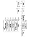
図1に、本実施形態の画像生成システム(ゲームシステム)の機能ブロック図の一例を示す。なお同図において本実施形態は、少なくとも処理部100を含めばよく(或いは処理部100と記憶部170を含めばよく)、それ以外の各部(機能ブロック)については任意の構成要素とすることができる。
【0036】
操作部160は、プレーヤが操作データを入力するためのものであり、その機能は、レバー、ボタン、ステアリング、シフトレバー、アクセルペダル、ブレーキペダル、マイク、センサー、或いは筺体などのハードウェアにより実現できる。
【0037】
記憶部170は、処理部100や通信部196などのワーク領域となるもので、その機能はRAMなどのハードウェアにより実現できる。
【0038】
情報記憶媒体180(コンピュータにより読み取り可能な媒体)は、プログラムやデータなどを格納するものであり、その機能は、光ディスク(CD、DVD)、光磁気ディスク(MO)、磁気ディスク、ハードディスク、磁気テープ、或いはメモリ(ROM)などのハードウェアにより実現できる。処理部100は、この情報記憶媒体180に格納されるプログラム(データ)に基づいて本実施形態の種々の処理を行う。即ち情報記憶媒体180には、本実施形態の各部(各手段)としてコンピュータを機能させるためのプログラム(各部をコンピュータに実現させるためのプログラム)が記憶(記録、格納)される。
【0039】
表示部190は、本実施形態により生成された画像を出力するものであり、その機能は、CRT、LCD、或いはHMD(ヘッドマウントディスプレイ)などのハードウェアにより実現できる。
【0040】
音出力部192は、本実施形態により生成された音を出力するものであり、その機能は、スピーカ、或いはヘッドフォンなどのハードウェアにより実現できる。
【0041】
携帯型情報記憶装置194は、プレーヤの個人データやゲームのセーブデータなどが記憶されるものであり、この携帯型情報記憶装置194としては、メモリカードや携帯型ゲーム装置などを考えることができる。
【0042】
通信部196は、外部(例えばホスト装置や他の画像生成システム)との間で通信を行うための各種の制御を行うものであり、その機能は、各種プロセッサ又は通信用ASICなどのハードウェアや、プログラムなどにより実現できる。
【0043】
なお本実施形態の各部(各手段)としてコンピュータを機能させるためのプログラム(データ)は、ホスト装置(サーバー)が有する情報記憶媒体からネットワーク及び通信部196を介して情報記憶媒体180(記憶部170)に配信するようにしてもよい。このようなホスト装置(サーバー)の情報記憶媒体の使用も本発明の範囲内に含まれる。
【0044】
処理部100(プロセッサ)は、操作部160からの操作データやプログラムなどに基づいて、ゲーム処理、画像生成処理、或いは音生成処理などの各種の処理を行う。この場合、処理部100は、記憶部170内の主記憶部172をワーク領域として使用して、各種の処理を行う。この処理部100の機能は、各種プロセッサ(CPU、DSP等)又はASIC(ゲートアレイ等)などのハードウェアや、プログラム(ゲームプログラム)により実現できる。
【0045】
ここで、処理部100が行う処理としては、コイン(代価)の受け付け処理、各種モードの設定処理、ゲームの進行処理、選択画面の設定処理、オブジェクト(1又は複数のプリミティブ)の位置や回転角度(X、Y又はZ軸回り回転角度)を求める処理、オブジェクトを動作させる処理(モーション処理)、視点の位置(仮想カメラの位置)や視線角度(仮想カメラの回転角度)を求める処理、マップオブジェクトなどのオブジェクトをオブジェクト空間へ配置する処理、ヒットチェック処理、ゲーム結果(成果、成績)を演算する処理、複数のプレーヤが共通のゲーム空間でプレイするための処理、或いはゲームオーバー処理などを考えることができる。
【0046】
処理部100は、移動・動作処理部110、オブジェクト空間設定部112、ヒットチェック部114、光源設定部116、基底光源選択部118、光源合成部119、画像生成部120、音生成部130を含む。なお、処理部100は、これらの各部(機能ブロック)を全て含む必要はなく、その一部を省略してもよい。
【0047】
移動・動作処理部110は、オブジェクト(移動体)の移動情報(位置、回転角度)や動作情報(オブジェクトの各パーツの位置、回転角度)を求める処理を行う。即ち、操作部160によりプレーヤが入力した操作データやゲームプログラムなどに基づいて、オブジェクトを移動させたり動作(モーション、アニメーション)させたりする処理を行う。
【0048】
より具体的には、移動・動作処理部110は、オブジェクト(移動体)の位置や回転角度を例えば1フレーム(1/60秒、1/30秒等)毎に変化させる。例えば(k−1)フレームでのオブジェクトの位置、回転角度をPk-1、θk-1とし、オブジェクトの1フレームでの位置変化量(速度)、回転変化量(回転速度)を△P、△θとする。するとkフレームでのオブジェクトの位置Pk、回転角度θkは例えば下式(1)、(2)のように求められる。
【0049】
Pk=Pk-1+△P (1)
θk=θk-1+△θ (2)
オブジェクト空間設定部112は、移動体(キャラクタ、車、戦車、ロボット)、柱、壁、建物、マップ(地形)などの各種オブジェクト(ポリゴン、自由曲面又はサブディビジョンサーフェスなどのプリミティブ面で構成されるオブジェクト)をオブジェクト空間内に配置設定するための処理を行う。より具体的には、ワールド座標系でのオブジェクトの位置や回転角度(方向)を決定し、その位置(X、Y、Z)にその回転角度(X、Y、Z軸回りでの回転)でオブジェクトを配置する。
【0050】
ヒットチェック部114は、オブジェクト(キャラクタ)に対して、攻撃(キック、パンチ又はショット等)がヒットしたか否かをチェックする処理を行う。具体的には、一方のオブジェクトの部位(手、足)や武器(剣、ショット)が、他方のオブジェクト(体、武器)にヒットしたか否かをチェックする。そして、他方のオブジェクトに攻撃がヒットした場合には、攻撃がヒットしたことをプレーヤに視覚的に伝えられるためのヒットエフェクト光(ヒットエフェクト画像)が生成される。また、他方のオブジェクトは、攻撃を受けたことを示すモーション(やられモーション、被ヒットモーション)を行うようになる。
【0051】
なお、オブジェクト(キャラクタ)の形状を簡略化して擬似的に表したヒットボリューム(ヒットボックス、ヒットエリア、簡易オブジェクト)や、オブジェクトの部位(手、足)や武器などが描く軌道を簡略化して擬似的に表したヒットボリュームを用いて、ヒットチェックを行うことが望ましい。
【0052】
光源設定部116は、複数の光源を設定(配置)する処理を行う。具体的には、オブジェクト(照明位置又はオブジェクトの代表位置)を照明するための複数の光源(論理的な光源)を用意し、複数の光源の各光源に対して、照明方向ベクトル、色、明度又は光源位置などの光源情報(属性情報)を設定する。
【0053】
なお、光源設定部116は、オブジェクトに対するヒットイベントが発生した場合に、ヒットチェック部114により検出されたヒット位置に、ヒットエフェクト光を表すための光源を設定(配置)する処理も行う。
【0054】
基底光源選択部118は、光源の明度(光源情報)に基づいて、複数の光源の中から基底光源(メイン光源、基準光源)を選択する処理(光源のソート処理)を行う。
【0055】
光源合成部119は、複数の光源を合成する処理(照明方向ベクトルの合成処理、色の合成処理等)を行い、合成光源(合成ベクトルや合成色などを、光源情報として有する光源)を求める処理を行う。より具体的には、光源設定部116により設定された複数の光源の照明方向ベクトルを合成し、合成光源の照明方向ベクトル(合成ベクトル)を求める。或いは、複数の光源に設定された色を合成することで、合成光源の色(合成色)を求める。
【0056】
この場合、光源合成部119は、例えば、照明方向ベクトルの内積(内積と数学的に均等なものを含む)や、明度の割合(明度を関数により変換したものの割合を含む)などに基づいて。光源の合成率(照明方向ベクトルの合成率、色の合成率又は光源位置の合成率等)を得る。
【0057】
また、光源合成部119は、基底光源選択部118により選択された基底光源(基底ベクトル)に対して、他の光源(照明方向ベクトル)を合成する処理を行う。そして、前のフレームで選択された光源とは異なる光源が基底光源選択部118により基底光源として選択された場合には、前のフレームで選択された光源の影響度(合成率)が、その後のフレーム経過に伴い徐々に減少するように、光源の合成を行う。これにより、光源の切り替わりが目立ってしまう事態を防止できる。
【0058】
画像生成部120は、処理部100で行われる種々の処理の結果に基づいて画像処理を行い、ゲーム画像を生成し、表示部190に出力する。例えば、いわゆる3次元のゲーム画像を生成する場合には、まず、座標変換、クリッピング処理、透視変換或いは光源処理等のジオメトリ処理が行われ、その処理結果に基づいて、描画データ(プリミティブ面の頂点(構成点)に付与される位置座標、テクスチャ座標、色(輝度)データ、法線ベクトル或いはα値等)が作成される。そして、この描画データ(プリミティブ面データ)に基づいて、ジオメトリ処理後のオブジェクト(1又は複数プリミティブ面)の画像が、描画バッファ174(フレームバッファ、ワークバッファ等のピクセル単位で画像情報を記憶できるバッファ)に描画される。これにより、オブジェクト空間内において仮想カメラ(所与の視点)から見える画像が生成されるようになる。
【0059】
音生成部130は、処理部100で行われる種々の処理の結果に基づいて音処理を行い、BGM、効果音、又は音声などのゲーム音を生成し、音出力部192に出力する。
【0060】
画像生成部120が含むシェーディング部122は、オブジェクトに陰影をつけるための処理を行う。より具体的には、光源情報(照明方向ベクトル、色又は光源位置等)、照明モデル、オブジェクトの法線ベクトル(頂点又は面の法線ベクトル)などに基づいてシェーディング処理を行う。
【0061】
ここで、シェーディング処理は、例えばオブジェクトの各点(ピクセル、ドット)での光の色(RGB、YCrCb、YUV、YIQ)を決定する処理と定義できる。そして、このシェーディング処理は、実世界での照明現象を模擬した数学的なモデルである照明モデルを用いて行われる。この照明モデルとしては、実世界現象のモデル化の態様に応じて、ランバード(Lambert)、フォン(Phong)、ブリン(Blinn)などの種々のモデルがある。また、プリミティブ面(ポリゴン、曲面等)の陰影づけを滑らかにして、プリミティブ面の境界を目立たなくする手法として、グーロー(Gouraud)シェーディング、フォン(Phong)シェーディングなどの種々のスムースシェーディング手法がある。
【0062】
なお、本実施形態の画像生成システムは、1人のプレーヤのみがプレイできるシングルプレーヤモード専用のシステムにしてもよいし、このようなシングルプレーヤモードのみならず、複数のプレーヤがプレイできるマルチプレーヤモードも備えるシステムにしてもよい。
【0063】
また複数のプレーヤがプレイする場合に、これらの複数のプレーヤに提供するゲーム画像やゲーム音を、1つの端末を用いて生成してもよいし、ネットワーク(伝送ライン、通信回線)などで接続された複数の端末(ゲーム機、携帯電話)を用いて生成してもよい。
【0064】
2.本実施形態の手法
次に本実施形態の手法について図面を用いて説明する。なお、以下では、格闘ゲームに本実施形態を適用した場合を主に例にとり説明するが、本実施形態は、格闘ゲーム以外の種々のゲームに広く適用できる。
【0065】
2.1 光源の合成
さて、よりリアルで高品質なゲーム画像を生成するためには、より多くの数の光源を用いてシェーディングを行うことが望ましい。
【0066】
しかしながら、光源の数が多くなると、その分だけシェーディングの処理負荷が重くなってしまうという問題がある。
【0067】
例えばグーローシェーディングでは、オブジェクトの頂点に設定された法線ベクトルと光源の照明方向ベクトルとの内積を求めることで、オブジェクトの各頂点色を求める。従って、オブジェクトの頂点数がI個であり、光源の数が1個の場合には、頂点色を求める処理がI回分だけ必要になる。従って、光源の数がJ個になると、頂点色を求める処理が(I×J)回分だけ必要になってしまう。
【0068】
通常、オブジェクトの頂点数Iは非常に多いため、このように光源数を増やすことによる処理負荷の増加は過大なものとなる。
【0069】
このような課題を解決するために本実施形態では以下のような手法を採用している。
【0070】
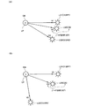
即ち、本実施形態では図2(A)に示すように、複数の光源LS1、LS2を用意する(3個以上用意してもよい)。
【0071】
例えば、光源LS1は、その照明方向ベクトルがV11であり、その色がC1であり、その明度がBR1(例えば色C1をグレースケールで表した時の明るさ)である。ここで、照明方向ベクトルV11は、光源LS1とオブジェクトOB1(照明位置又はOB1の代表位置LP1)とを結ぶ方向に沿ったベクトル(単位ベクトル)である。
【0072】
また、光源LS2は、その照明方向ベクトルがV21であり、その色がC2であり、その明度がBR2である。ここで、照明方向ベクトルV21は、光源LS2とオブジェクトOB1(照明位置又は代表位置LP1)とを結ぶ方向に沿ったベクトル(単位ベクトル)である。
【0073】
本実施形態では図2(A)に示すように、これらの光源LS1、LS2(論理的な光源)を合成することで、オブジェクトOB1に対する合成光源LSS1(シェーディング用の光源)を求める。
【0074】
より具体的には、オブジェクトOB1に対する光源LS1、LS2の照明方向ベクトルV11、V21を合成し、合成光源LSS1の照明方向ベクトルVS1(単位ベクトル)を求める。また、光源LS1、LS2の色C1、C2を合成し、合成光源LSS1の色CS1を求める。
【0075】
そして、この求められた合成光源LSS1を用いて、オブジェクトOB1に対するシェーディングを行う。即ち、光源LS1、LS2の代わりに、照明方向ベクトルがVS1で色がCS1である合成光源LSS1(平行光源)が仮想的に存在すると考え、この合成光源LSS1だけを用いてシェーディングを行う。
【0076】
一方、オブジェクトOB2については、図2(B)に示すような合成処理を行う。即ち、光源LS1、LS2を合成することで、オブジェクトOB2(照明位置又はOB2の代表位置LP2)に対する合成光源LSS2を求める。
【0077】
より具体的には、オブジェクトOB2に対する光源LS1、LS2の照明方向ベクトルV12、V22を合成し、合成光源LSS2の照明方向ベクトルVS2を求める。また、光源LS1、LS2の色C1、C2を合成し、合成光源LSS2の色CS2を求める。
【0078】
そして、この求められた合成光源LSS2を用いて、オブジェクトOB2に対するシェーディングを行う。
【0079】
このようにすれば、論理的な光源(LS1、LS2)は複数個存在するにも拘わらず、シェーディング用の物理的な光源は例えば1個で済むため、シェーディングの処理負荷を軽減できる。例えば、オブジェクトの頂点数がI個である場合には、頂点色を求める処理は、各オブジェクトについてI回分だけ行えば済むようになる。
【0080】
そして、本実施形態では、論理的な光源(LS1、LS2)が複数個存在するため、光源が1個しか存在しない場合に比べてリアルな画像表現が可能になる。例えば、光源LS1、LS2の位置関係や色の関係に応じて、合成光源の照明方向ベクトルや色が様々に変化するようになる。また、図2(A)、(B)から明らかなように、オブジェクト毎に、或いはオブジェクトと光源との位置関係に応じて、シェーディングに使用される合成光源は異なったものになり、異なったシェーディングが施されるようになる。
【0081】
例えば本実施形態と異なる手法として、複数の光源を用意し、オブジェクトとの位置関係に基づいて、その複数の光源の中から適当な1つの光源を選択し、選択された光源を用いてオブジェクトのシェーディングを行う手法が考えられる。
【0082】
しかしながら、この手法では、例えば図2(A)において光源LS1が選択された場合には、光源LS2の影響が全く無視されてしまう。逆に、光源LS2が選択された場合には、光源LS1の影響が全く無視されてしまう。
【0083】
即ち、光源LS1が選択された場合には照明方向はV11の方向になり、LS2が選択された場合にはV21の方向になるというように、照明方向が択一的になってしまう。同様に、光源LS1の色が白でLS2の色が赤であったとすると、LS1が選択された場合には白の陰影づけだけがオブジェクトに施され、LS2が選択された場合には赤の陰影づけだけが施されるようになり、陰影づけされる色も択一的になってしまう。従って、今ひとつリアルな画像を生成できない。
【0084】
これに対して本実施形態では、合成光源LSS1の照明方向、色は、光源LS1の照明方向、色のみならず、光源LS2の照明方向、色の影響も受けるようになる。従って、上記の手法に比べて、得られる画像のリアル度を格段に高めることができる。
【0085】
なお、以下では、説明を簡単にするために、2個又は3個の数の光源を合成する場合を主に例にとり説明する。しかしながら、この明細書で説明する本実施形態の手法は、3個以上又は4個以上の数の光源を使用する場合にも当然に拡張できる。
【0086】
2.2 光源の合成率
さて、本実施形態では光源の合成率(照明方向ベクトルの合成率、色の合成率)を、以下に説明する手法で求めている。
【0087】
例えば、図3(A)において、光源LS1、LS2の明度をBR1、BR2とした場合に、明度の割合BRP(例えばBRP=BR2/BR1)を求める。
【0088】
また、光源LS1、LS2の照明方向ベクトルV1、V2の内積VIP=V1・V2を求める。
【0089】
次に、これらの明度割合BRPと内積VIPに基づいて、合成率γ=F(BRP、VIP)を求める。ここで、F(BRP、VIP)は、BRP、VIPを引数とする関数である。
【0090】
そして、この合成率γを用いて、光源LS1、LS2の照明方向ベクトルV1、V2を合成し、合成光源LSSの照明方向ベクトルVSを求める。或いは、LS1、LS2の色C1、C2を合成し、LSSの色CSを求める。
【0091】
VS=V1+γ×V2 (3)
CS=C1+γ×C2 (4)
なお、上式(3)のベクトル合成処理は、ベクトルVS、V1、V2のX、Y、Z座標の各々について行う。また、上式(4)の色合成処理は、色CS、C1、C2のR、G、B成分(広義には第1〜第3の成分)の各々について行う。
【0092】
また、上式(3)、(4)は、加算ブレンディング方式を採用しているが、下式のような狭義のブレンディング方式を採用してもよい。
【0093】
VS=(1−γ)×V1+γ×V2 (5)
CS=(1−γ)×C1+γ×C2 (6)
また、合成率γを求める際に使用する明度割合(明度比率)BRPは、BR1、BR2そのものの割合(比率)であってもよいし、BR1、BR2を関数等で変換することで得られるBR1’、BR2’の割合であってもよい。
【0094】
また、合成率γを求める関数Fとしては、例えばF(BRP、VIP)=K×BRP×VIP(Kは定数)を考えることができる。また、関数G、Hを用いて、F(BRP、VIP)=K×G(BRP)×H(VIP)とすることもできる。ここで、関数G、Hとしては、引数を非線形変換する関数(正弦関数、余弦関数、n次式)などを採用できる。
【0095】
また、合成率γを、内積VIPのみに基づいて求めたり、明度割合BRPにのみに基づいて求めてもよい。
【0096】
以上のように本実施形態では、光源LS1、LS2の照明方向ベクトルV1、V2の内積VIPを用いて合成率γを求めている。従って、図3(A)、(B)に示すように、照明方向ベクトルV1、V2間のなす角度に応じて、合成率γも変化するようになり、多様な画像表現を実現できる。
【0097】
より具体的には、内積VIPを用いて合成率γを求めるようにすれば、図3(B)のようにV1とV2のなす角度が大きくなって90度に近づいたとしても、合成光源LSSの照明方向ベクトルVSの向きを、V2の方向よりもV1の方向に常に近づけるようにすることができる。これにより、例えば照明ベクトルV1(基底ベクトル)を、常に支配的な光源に設定できるようになる。
【0098】
また本実施形態では、光源LS1、LS2の明度BR1、BR2の割合BRPを用いて合成率γを求めている。従って、明度(RGBをグレースケール変換した時の明るさ等)の高い方の光源を支配的な光源に設定することが可能になる。例えば、図3(A)、(B)において、光源LS1の明度BR1の方が明るい場合には、合成光源LSSの照明方向ベクトルVSの向きが、V2の方向よりもV1の方向に近づくようになる。
【0099】
2.3 疑似点光源
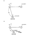
本実施形態では平行光源を用いて点光源を擬似的に表現している。
【0100】
即ち図4(A)において、光源LS1は通常の平行光源(例えば日光)に設定され、光源LS2は疑似点光源(例えば松明)に設定されている。そして、この場合には、オブジェクトOB(照明位置又はOBの代表位置LP)と疑似点光源LS2との距離DIS(広義には位置関係)を求める。そして、疑似点光源LS2の明度BR2を、この距離DISに応じて変化(減衰)させる。具体的には、例えば、BR2=BR2/DISn(例えばn=3)という変換を行う。また、点光源LS2の照明方向ベクトルV2を、LS2からOB(LP)へと向かう方向のベクトルに設定する。
【0101】
このようにすることで、平行光源を用いながら、擬似的に点光源を表現できるようになる。
【0102】
即ち、図4(B)に示すように、オブジェクトOBと疑似点光源LS2との位置関係(距離関係、方向関係)が変化すると、OBに対するLS2の明度BR2が変化(増減)したり、照明方向ベクトルV2の方向が変化するようになる。
【0103】
なお、平行光源(例えば日光)として設定された光源LS1については、その明度BR1や照明方向ベクトルV1の方向は、オブジェクトOBが移動しても一定になる。但し、BR1やV1の方向を、時間経過やゲームイベントの発生に伴い変化させるようにしてもよい。
【0104】
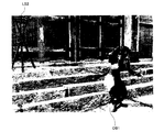
図5、図6に、本実施形態により生成される画像の例を示す。
【0105】
図5は、ゲームフィールド(オブジェクト空間)の全体を示す画像の例である。このゲームフィールドには、日光を表現する光源LS1や、松明を表現する疑似点光源LS2などが設定されており、これらの光源LS1、LS2を用いてオブジェクト(キャラクタ)OB1、OB2のシェーディングが行われる。
【0106】
図6は、図2(A)、(B)の手法で光源LS1、LS2を合成し、求められた合成光源を用いてオブジェクトOB1をシェーディングした場合の画像の例である。
【0107】
図6に示すように、本実施形態によれば、オブジェクトOB1の体全体が、光源LS1、LS2の合成光源により自然にシェーディングされるようになる。また、合成光源の色は、日光(LS1)の白と松明(LS2)の赤が合成された色になる。従って、あたかも2つの光源でシェーディングしたかのように見えるリアルな画像を提供できる。また、オブジェクトOB1が、松明(LS2)から離れた位置から松明の方に近づいて行った場合に、日光により支配的にシェーディングされる状態から、松明により支配的にシェーディングされる状態に徐々に移行するようになり、より自然な画像表現が可能になる。
【0108】
なお、図7に、日光(LS1)だけを用いてオブジェクトOB1をシェーディングした場合の画像の例を示し、図8に、松明(LS2)だけを用いてOB1をシェーディングした場合の画像の例を示す。
【0109】
図7では、松明(LS2)からの光の影響が、オブジェクトOB1のシェーディングの際に考慮されず、日光(LS1)の白の光だけでシェーディングされてしまうため、図6に比べて今ひとつリアルな画像を表現できない。また、図8では、松明(LS2)からの赤の色の光だけでオブジェクトOB1がシェーディングされてしまうため、不自然な画像になってしまう。
【0110】
この場合、例えば、オブジェクトOB1が松明(LS2)に近づいた時に、所与のタイミングで、日光(LS1)だけを用いるシェーディングから、松明(LS2)だけを用いるシェーディングに切り替える手法を考えることもできる。
【0111】
しかしながら、この手法によると、プレーヤの見る画像が、図7の画像から図8の画像に突然切り替わる事態が生じてしまい、プレーヤが不自然さを感じる。
【0112】
図2(A)、(B)の本実施形態によれば、光源LS1、LS2の合成光源でオブジェクトOB1がシェーディングされるため、上記のような事態を防止でき、より自然でリアルな画像を生成できる。
【0113】
2.4 基底光源
本実施形態では、光源を合成する前に、複数の光源の中から基底光源(メイン光源、基準光源)を、まず選択する。そして、この選択された基底光源に対して、他の光源を合成するようにしている。
【0114】
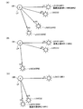
より具体的には、例えば図9(A)では、光源LS1が基底光源として選択されている。この基底光源の選択は、例えば光源の明度(広義には光源情報)に基づいて行う。そして、明度が最も高い光源を基底光源として選択する。図9(A)では、光源LS1〜LS3のうち、LS1の明度BR1がLS2、LS3の明度BR2、BR3よりも高いため、LS1が基底光源として選択される。
【0115】
本実施形態では、このようにして選択された基底光源LS1に対して、他の光源LS2、LS3を合成する。
【0116】
即ち、図2(A)〜図4(B)で説明した手法を用いて、基底光源LS1の照明方向ベクトルV1に対して、光源LS2、LS3の照明方向ベクトルV2、V3を合成する。また、LS1の色C1に対して、LS2、LS3の色C2、C3を合成する。そして、得られた合成光源LSS(合成ベクトルVS、合成色CS)でオブジェクトOB(LP)をシェーディングする。
【0117】
この場合に本実施形態では、基底光源よりも他の光源の合成率が低くなるように、基底光源に対して他の光源を合成している。
【0118】
従って、図9(B)に示すように、LS1の明度BR1の方がLS2のBR2より高く、LS1が基底光源として選択された場合には、合成光源LSSの照明方向ベクトルVSの方向が、V2の方向よりもV1の方向に近づくようになる。また、図9(C)に示すように、LS2の明度BR2の方がLS1のBR1より高く、LS2が基底光源として選択された場合には、VSの方向が、V1の方向よりもV2の方向に近づくようになる。即ち、合成光源の照明方向ベクトルの方向を、明度が高い基底光源の照明ベクトルの方向の方に自動的に近づけることができる。これにより、明度が高い基底光源を支配的な光源に設定して、オブジェクトOBをシェーディングすることが可能になる。
【0119】
例えば図5に示すゲームフィールドにおいて、オブジェクトOB1と疑似点光源LS2(松明)との距離が遠い場合には、図4(A)、(B)で説明したようにOB1に対する疑似点光源LS2の明度は低くなる。従って、この場合には、LS2に比べて明度が高い光源LS1(日光)が基底光源として選択され、LS1の照明方向にほぼ一致する照明方向で、オブジェクトOB1がシェーディングされるようになる。
【0120】
一方、オブジェクトOB1が疑似点光源LS2(松明)に近づくと、OB1、LS2間の距離が短くなり、OB1に対する疑似点光源LS2の明度は高くなる。そして、OB1、LS2間が所与の距離になると、LS2(松明)の明度の方がLS1(日光)の明度よりも高くなり、LS2が基底光源として選択される。これにより、LS2の照明方向に近い照明方向で、オブジェクトOB1がシェーディングされるようになる。
【0121】
従って、OB1、LS2間の距離が遠い場合には、LS1(日光)が支配的な光源になるシェーディングが行われ、OB1、LS2間の距離が近い場合には、LS2(松明)が支配的な光源になるシェーディングが行われるようになる。
【0122】
さて、図9(A)に示す手法を採用すると、例えば基底光源がLS1からLS2に切り替わった際に、合成光源LSSの照明方向ベクトルVSの方向が、図9(B)、図9(C)に示すように急激に切り替わってしまう可能性がある。また、合成光源LSSの色CSが、例えば白(日光)から赤(松明)に急激に切り替わってしまう可能性がある。
【0123】
そこで本実施形態では、基底光源が、例えばLS1(第Nのフレームの第Kの光源)からLS2(第N+1のフレームの第Lの光源)に切り替わった場合に、合成処理に対するLS1の影響度(合成率)が、フレーム経過に伴い徐々に減少するように、光源の合成処理を行っている。
【0124】
即ち図10(A)に示すように、合成光源LSSのVSの方向が、LS1のV1の方向から、LS2のV2の方向の方に徐々に変化するように、光源の合成処理を行っている。また、合成光源LSSの色CSが、LS1の色C1から、LS2の色C2の方に徐々に変化するように、光源の合成処理を行っている。
【0125】
より具体的には、このような合成処理は例えば以下のような手法で実現できる。
【0126】
即ち、図10(B)に示すように、前回のフレーム(第Nのフレーム)で得られた合成光源LSS’の情報(VS’、CS’)を破棄せずに取っておく。そして、この前回(過去)のフレームの合成光源LSS’と、現在のフレーム(第N+1のフレーム)の合成光源LSSを合成し、最終的な合成光源LSSLを求める。そして、このLSSLを用いてオブジェクトOBをシェーディングする。
【0127】
例えば、前回のフレームの合成光源LSS’の照明方向ベクトルVS’、色CS’と、現在のフレームの合成光源LSSの照明方向ベクトルVS、色CSとを、合成率GRを用いて下式のように合成し、最終的な合成光源LSSLの照明方向ベクトルVSL、色CSLを求める。
【0128】
VSL=(1.0−GR)×VS’+GR×VS (7)
CSL=(1.0−GR)×CS’+GR×CS (8)
なお、上式(7)、(8)に示すような狭義のブレンディング方式ではなく、前述した式(3)、(4)のような加算ブレンディング方式で合成処理を行ってもよい。
【0129】
また、上式の合成率GRを、可変に制御するようにしてもよい。
【0130】
例えば、基底光源の切り替わりの際に、図9(B)の状態から図9(C)の状態に素早く移行させたい場合には、合成率GRを1.0(最大値)に設定したり、1.0に近い値に設定する。
【0131】
このようにすれば、上式(7)、(8)から明らかなように、前回(過去)のフレームの合成光源LSS’のVS’、CS’が、最終的な合成光源LSSLのVSL、CSLに対して与える影響が少なくなる。これにより、光源の素早い切替が可能になる。
【0132】
一方、基底光源の切り替わりの際に、図10(A)に示すように、LSSのVSやCSを徐々に変化させたい場合には、GRを小さな値(0.0に近い値)に設定する。或いは、小さな値から大きな値にフレーム経過に伴い変化するように、GRを設定する。
【0133】
このようにすれば、上式(7)、(8)から明らかなように、前回(過去)のフレームの合成光源LSS’のVS’、CS’の影響が強く残るようになる。これにより、最終的な合成光源LSSLのVSL、CSLがゆっくりと変化するようになり、より自然で滑らかな光源の切替が可能になる。
【0134】
2.5 アンビエント光への付加
本実施形態では、複数の光源のうち、合成処理の対象とならなかった光源の色を、アンビエント光の色に付加するようにしている。
【0135】
例えば図11(A)では、光源LS1、LS2、LS3を合成することで、合成光源LSSが求められ、LSSに基づいてオブジェクトOBのシェーディングが行われている。
【0136】
一方、図11(B)では、オブジェクトOBが移動しており、OBとLS1、LS2、LS3の位置関係が変化している。そして図11(B)では、基底光源となるLS1の照明方向ベクトルV1と、光源LS2の照明方向ベクトルV2とのなす角度が90度(直角)以上になっている。
【0137】
このような場合に、光源LS2の影響がLSSの合成処理に及んだままになると、不自然な事態が生じるおそれがある。特に、光源の合成率γを、図3(A)、(B)に示すように内積値VIPに基づいて求めている場合には、V1とV2のなす角度が90度よりも広がると、VIPが負の値になってしまい、合成率γを適切に求めることができなくなるおそれがある。
【0138】
そこで本実施形態では、図11(B)のようにV1とV2のなす角度が90度以上になった場合には、光源LS2を合成処理の対象から除外している。そして、この除外された光源LS2の色C2を、アンビエント光の色(RGB)に付加する。
【0139】
このようにすれば、光源LS2は、合成処理の対象からは除外されるものの、その影響は、アンビエント光の色として残るようになる。
【0140】
例えば図5において、オブジェクトOB1と松明(LS2)の位置関係が変化し、松明が光源の合成処理の対象から除外された場合を考える。このような場合に、松明(LS2)による照明の影響が全く無くなってしまうと、今ひとつリアルな画像を生成できない。
【0141】
本実施形態では、このような場合にも、松明(LS2)の色(赤)がアンビエント光の色に付加される。従って、松明による赤の照明の影響が少なからず残るようになり、少ない処理でリアルな画像の生成が可能になる。
【0142】
なお、図11(B)において光源LS2を合成処理の対象から除外するか否かは、V1とV2の内積VIPが負になったか否かで判断することが望ましいが、これとは異なる基準で判断するようにしてもよい。
【0143】
また、LS2の色C2そのものをアンビエント光の色に付加する代わりに、C2に変換処理を施し、変換処理後のC2をアンビエント光の色に付加するようにしてもよい。
【0144】
2.6 ヒットイベント時のエフェクト光
格闘ゲームなどにおいては、一方のオブジェクト(キャラクタ)の攻撃(武器、キック、パンチ)が他方のオブジェクトにヒットするヒットイベントの発生時に、ヒットイベントが発生したことをプレーヤに視覚的に伝えるヒットエフェクト光を表示することが望ましい。
【0145】
本実施形態では、このヒットエフェクト光の表示を、図2(A)、(B)で説明した光源合成処理で実現している。
【0146】
例えば図12(A)では、オブジェクトOB2(キャラクタ)の攻撃(武器)がオブジェクトOB1にヒットしている。そして、ヒットチェック処理により、ヒット位置としてHP1、HP2、HP3、HP4が検出されている。
【0147】
この場合に本実施形態では図12(B)に示すように、これらの複数のヒット位置HP1、HP2、HP3、HP4に、ヒットエフェクト光を表現するための光源LS1、LS2、LS3、LS4を設定(配置)する。
【0148】
そして、これらの光源LS1〜LS4を図2(A)、(B)で説明した手法により合成することで、図13(A)に示すように、合成光源LSS1を求める。そして、求められた合成光源LSS1に基づいてオブジェクトOB1のシェーディングを行う。
【0149】
より具体的には、光源LS1〜LS4からオブジェクトOB1の代表位置LP1に向かう方向の照明方向ベクトルを求める。そして、これらの照明方向ベクトルを合成し、合成光源LSS1の照明方向ベクトルVS1を求める。また、光源LS1〜LS4の色を合成し、合成光源LSS1の色CS1を求める。
【0150】
そして、求められた照明方向ベクトルLSS1、色CS1を用いて、オブジェクトOB1の各頂点の色などを求め、OB1のシェーディングを行う。
【0151】
一方、オブジェクトOB2については、図13(B)に示すような合成光源LSS2を求める。そして、求められた合成光源LSS2に基づいてオブジェクトOB2のシェーディングを行う。
【0152】
より具体的には、光源LS1〜LS4からオブジェクトOB2の代表位置LP2に向かう方向の照明方向ベクトルを求める。そして、これらの照明方向ベクトルを合成し、合成光源LSS2の照明方向ベクトルを求める。また、光源LS1〜LS4の色を合成し、合成光源LSS2の色CS2を求める。そして、求められた照明方向ベクトルLSS2、色CS2を用いて、オブジェクトOB2の各頂点の色などを求め、OB2のシェーディングを行う。
【0153】
図14に、図12(A)〜図13(B)の本実施形態の手法により生成される画像の例を示す。
【0154】
このように本実施形態によれば、あたかも複数個の光源で構成されているかのように見えるヒットエフェクト光を、簡素な処理で生成できる。
【0155】
しかも、ヒットチェックにより検出されたヒット位置に複数の光源を配置するだけで、その後の光源合成処理は自動的に行われる。従って、ヒット位置に応じて処理内容を変えるなどの煩雑な処理を必要とすることなく、ヒット位置を反映した適正な合成光源で、オブジェクトをシェーディングすることが可能になる。
【0156】
また、本実施形態によれば、図13(A)、(B)に示すように、同じヒット位置に基づいて、オブジェクトOB1用の合成光源LSS1と、オブジェクトOB2用の合成光源LSS2の両方を自動的に生成できる。そして、これらのLSS1、LSS2を用いることで、オブジェクトOB1、OB2に対して、異なったシェーディングを施すことが可能になり、よりリアルなシェーディングを実現できる。
【0157】
なお、ヒットイベントが発生する前においては、合成光源LSS1やLSS2に使用されるシェーディング用の物理的な光源を、他の用途に使用することが望ましい。ここで、他の用途としては、例えば、オブジェクトの逆光部分を照明する逆光補正用の光源などの用途が考えられる。そして、ヒットイベントが発生したことを条件に、このシェーディング用の物理的な光源を、図13(A)、(B)に示すようなヒットエフェクト光の光源に使用するようにすればよい。
【0158】
また、ヒットエフェクト光の生成時には、図10(A)、(B)や上式(7)、(8)で説明した合成率GR(移行速度)を、なるべく大きな値に設定することが望ましい。例えば、ヒットエフェクト光の生成時には、上式(7)、(8)においてGR=1.0に設定する。このようにすることで、例えば他の用途の光源(逆光補正用の光源)からヒットエフェクト用の光源への切替を素早く行うことが可能になる。
【0159】
3.本実施形態の処理
次に、本実施形態の処理の詳細例について、図15、図16、図17のフローチャートを用いて説明する。
【0160】
まず、各光源について、オブジェクト(照明位置)に対する照明方向ベクトルと明度(減衰度)を決定する(ステップS1)。ここで、減衰率は、図4(A)、(B)で説明した疑似点光源の明度の減衰率である。そして、全ての光源について処理が終了するまで処理を繰り返す(ステップS2)。
【0161】
次に、ステップS1で決定した明度(減衰後の明度)に基づき、オブジェクトを照明する光源を、明るい順になるようにソートする(ステップS3)。即ち、明度が最も高い光源が先頭になるようにソートする。そして、全ての光源のソートが終了するまで処理を繰り返す(ステップS4)。
【0162】
次に、処理対象となる光源が、ソートされた光源のうちの先頭の光源か否かを判断する(図16のステップS5)。そして、先頭の光源である場合には、その光源が、前回のフレームで基底光源として使用した光源と同じか否かを判断する(ステップS6)。そして、同じ光源である場合にはステップS10に移行する。
【0163】
一方、違う光源である場合(基底光源が切り替わった場合)には、合成率GRの移行速度SSを早くするか否かを判定する(ステップS7)。そして、速くする場合(図12(A)〜図14のヒットエフェクト光の場合)には、SSを1.0(最大値)に設定する(ステップS8)。一方、速くしない場合(図5の日光と松明の場合)には、SSを0.0(最小値)に設定する(ステップS9)。
【0164】
次に、処理対象光源を基底光源に設定する(ステップS10)。より具体的には、基底光源(図9(A)〜(C)参照)の照明方向ベクトルを基底ベクトルVBに設定すると共に合成ベクトルVSの初期値に設定する。また、基底光源の明度を基底明度BRBに設定し、基底光源の色を合成色CSの初期値に設定する。そして、追従度Tを1.0に設定し(ステップS11)、ステップS19に移行する。
【0165】
ステップS5で、処理対象光源が先頭の光源ではないと判断された場合には、基底明度BRBに対する、処理対象光源の明度BRの割合BRPを求め、求められたBRPを0.0〜1.0の範囲にリミットする(ステップS12)。また、基底ベクトルVBと処理対象光源の照明方向ベクトルVとの内積VIPを求める(ステップS13)。
【0166】
次に、内積VIPが負の値か否かを判断し(ステップS14)、VIP<0の場合には、処理対象光源の色CとVIPに基づき、アンビエント光の色に付加すべき色CAを求める(ステップS15。図11(A)、(B)参照)。
【0167】
一方、VIP≧0の場合には、明度割合BRPと内積VIPに基づいて、合成率γ=F(BRP,VIP)を求める(ステップS16。図3(A)、(B)参照)。
【0168】
次に、基底光源と処理対象光源の明度が近いほど小さな値になる追従度T={T+(1−BRP)}×0.5を設定する(ステップS17)。
【0169】
次に、求まった合成率γと、処理対象光源の照明方向ベクトルV及び色Cに基づいて、合成ベクトルVS=VS+γ×V、合成色CS=CS+γ×Cを求める。(ステップS18。図2(A)、(B)、図9(A)、(B)、(C)参照)。そして、全ての処理対象光源を処理したか否かを判断し(ステップS19)、処理していない場合にはステップS5に戻る。
【0170】
次に、合成ベクトルVSを正規化する(図17のステップS20)。そして、過去の合成ベクトルとの合成率GRをコントロールするか否かを判断する(ステップS21)。
【0171】
そして、GRをコントロールする場合には、GR=T3に設定し、得られたGRを0.1〜1.0の範囲にリミットする(ステップS22)。このようにすることで、GRは、T=1.0付近で急峻に0.0から1.0に変化するようになる。一方、GRをコントロールしない場合には、GR=1.0に設定する(ステップS23)。
【0172】
次に、GR=GR×SSに設定し、得られたGRを0.05〜1.0の範囲にリミットする(ステップS24)。GR≧0.05となるようにGRをリミットすることで、移行速度SS=0.0の場合にも、GRが0.05よりも小さくならないことが保証されるようになる。
【0173】
次に、移行速度SS=SS+1/M(例えばM=24)に設定し、得られたSSを0.0〜1.0の範囲にリミットする(ステップS25)。このようにすることで、移行速度SSが、フレーム経過に伴い徐々に増加するようになる。
【0174】
次に、前回のフレームの合成ベクトルVS’と、今回のフレームの合成ベクトルVSと、合成率GRに基づき、最終合成ベクトルVSL=(1.0−GR)×VS’+GR×VSを求める(ステップS26。図10(B)参照)。
【0175】
また、前回のフレームの合成色CS’と、今回のフレームの合成色CSと、合成率GRに基づき、最終合成色CSL=(1.0−GR)×CS’+GR×CSを求める(ステップS27)。
【0176】
そして、求められた最終合成ベクトルVSLと、最終合成色CSLと、移行速度SSを、次のフレームの処理に使用するために主記憶部に保存する(ステップS28)。
【0177】
最後に、最終合成ベクトルVSL、最終合成色CSLに基づき、オブジェクトのシェーディングを行う(ステップS29)。
【0178】
以上のようにすることで、当該フレームでの光源の合成処理が完了し、オブジェクトをシェーディングすることができる。
【0179】
4.ハードウェア構成
次に、本実施形態を実現できるハードウェアの構成の一例について図18を用いて説明する。
【0180】
メインプロセッサ900は、CD982(情報記憶媒体)に格納されたプログラム、通信インターフェース990を介して転送されたプログラム、或いはROM950(情報記憶媒体の1つ)に格納されたプログラムなどに基づき動作し、ゲーム処理、画像処理、音処理などの種々の処理を実行する。
【0181】
コプロセッサ902は、メインプロセッサ900の処理を補助するものであり、高速並列演算が可能な積和算器や除算器を有し、マトリクス演算(ベクトル演算)を高速に実行する。例えば、オブジェクトを移動させたり動作(モーション)させるための物理シミュレーションに、マトリクス演算などの処理が必要な場合には、メインプロセッサ900上で動作するプログラムが、その処理をコプロセッサ902に指示(依頼)する。
【0182】
ジオメトリプロセッサ904は、座標変換、透視変換、光源計算、曲面生成などのジオメトリ処理を行うものであり、高速並列演算が可能な積和算器や除算器を有し、マトリクス演算(ベクトル演算)を高速に実行する。例えば、座標変換、透視変換、光源計算などの処理を行う場合には、メインプロセッサ900で動作するプログラムが、その処理をジオメトリプロセッサ904に指示する。
【0183】
データ伸張プロセッサ906は、圧縮された画像データや音データを伸張するデコード処理を行ったり、メインプロセッサ900のデコード処理をアクセレートする処理を行う。これにより、オープニング画面、インターミッション画面、エンディング画面、或いはゲーム画面などにおいて、MPEG方式等で圧縮された動画像を表示できるようになる。なお、デコード処理の対象となる画像データや音データは、ROM950、CD982に格納されたり、或いは通信インターフェース990を介して外部から転送される。
【0184】
描画プロセッサ910は、ポリゴンや曲面などのプリミティブ(プリミティブ面)で構成されるオブジェクトの描画(レンダリング)処理を高速に実行するものである。オブジェクトの描画の際には、メインプロセッサ900は、DMAコントローラ970の機能を利用して、オブジェクトデータを描画プロセッサ910に渡すと共に、必要であればテクスチャ記憶部924にテクスチャを転送する。すると、描画プロセッサ910は、これらのオブジェクトデータやテクスチャに基づいて、Zバッファなどを利用した陰面消去を行いながら、オブジェクトをフレームバッファ922に高速に描画する。また、描画プロセッサ910は、αブレンディング(半透明処理)、デプスキューイング、ミップマッピング、フォグ処理、バイリニア・フィルタリング、トライリニア・フィルタリング、アンチエリアシング、シェーディング処理なども行うことができる。そして、1フレーム分の画像がフレームバッファ922に書き込まれると、その画像はディスプレイ912に表示される。
【0185】
サウンドプロセッサ930は、多チャンネルのADPCM音源などを内蔵し、BGM、効果音、音声などの高品位のゲーム音を生成する。生成されたゲーム音は、スピーカ932から出力される。
【0186】
ゲームコントローラ942(レバー、ボタン、筺体、パッド型コントローラ又はガン型コントローラ等)からの操作データや、メモリカード944からのセーブデータ、個人データは、シリアルインターフェース940を介してデータ転送される。
【0187】
ROM950にはシステムプログラムなどが格納される。なお、業務用ゲームシステムの場合には、ROM950が情報記憶媒体として機能し、ROM950に各種プログラムが格納されることになる。なお、ROM950の代わりにハードディスクを利用するようにしてもよい。
【0188】
RAM960は、各種プロセッサの作業領域として用いられる。
【0189】
DMAコントローラ970は、プロセッサ、メモリ(RAM、VRAM、ROM等)間でのDMA転送を制御するものである。
【0190】
CDドライブ980は、プログラム、画像データ、或いは音データなどが格納されるCD982(情報記憶媒体)を駆動し、これらのプログラム、データへのアクセスを可能にする。
【0191】
通信インターフェース990は、ネットワークを介して外部との間でデータ転送を行うためのインターフェースである。この場合に、通信インターフェース990に接続されるネットワークとしては、通信回線(アナログ電話回線、ISDN)、高速シリアルバスなどを考えることができる。そして、通信回線を利用することでインターネットを介したデータ転送が可能になる。また、高速シリアルバスを利用することで、他の画像生成システムとの間でのデータ転送が可能になる。
【0192】
なお、本実施形態の各部(各手段)は、その全てを、ハードウェアのみにより実現してもよいし、情報記憶媒体に格納されるプログラムや通信インターフェースを介して配信されるプログラムのみにより実現してもよい。或いは、ハードウェアとプログラムの両方により実現してもよい。
【0193】
そして、本実施形態の各部をハードウェアとプログラムの両方により実現する場合には、情報記憶媒体には、ハードウェア(コンピュータ)を本実施形態の各部として機能させるためのプログラムが格納されることになる。より具体的には、上記プログラムが、ハードウェアである各プロセッサ902、904、906、910、930等に処理を指示すると共に、必要であればデータを渡す。そして、各プロセッサ902、904、906、910、930等は、その指示と渡されたデータとに基づいて、本発明の各部を実現することになる。
【0194】
図19(A)に、本実施形態を業務用ゲームシステム(画像生成システム)に適用した場合の例を示す。プレーヤは、ディスプレイ1100上に映し出されたゲーム画像を見ながら、操作部1102(レバー、ボタン)を操作してゲームを楽しむ。内蔵されるシステムボード(サーキットボード)1106には、各種プロセッサ、各種メモリなどが実装される。そして、本実施形態の各部を実現するためのプログラム(データ)は、システムボード1106上の情報記憶媒体であるメモリ1108に格納される。以下、このプログラムを格納プログラム(格納情報)と呼ぶ。
【0195】
図19(B)に、本実施形態を家庭用のゲームシステム(画像生成システム)に適用した場合の例を示す。プレーヤはディスプレイ1200に映し出されたゲーム画像を見ながら、コントローラ1202、1204などを操作してゲームを楽しむ。この場合、上記格納プログラム(格納情報)は、本体システムに着脱自在な情報記憶媒体であるCD1206、或いはメモリカード1208、1209などに格納されている。
【0196】
図19(C)に、ホスト装置1300と、このホスト装置1300とネットワーク1302(LANのような小規模ネットワークや、インターネットのような広域ネットワーク)を介して接続される端末1304-1〜1304-n(ゲーム機、携帯電話)とを含むシステムに本実施形態を適用した場合の例を示す。この場合、上記格納プログラム(格納情報)は、例えばホスト装置1300が制御可能な磁気ディスク装置、磁気テープ装置、メモリなどの情報記憶媒体1306に格納されている。端末1304-1〜1304-nが、スタンドアロンでゲーム画像、ゲーム音を生成できるものである場合には、ホスト装置1300からは、ゲーム画像、ゲーム音を生成するためのゲームプログラム等が端末1304-1〜1304-nに配送される。一方、スタンドアロンで生成できない場合には、ホスト装置1300がゲーム画像、ゲーム音を生成し、これを端末1304-1〜1304-nに伝送し端末において出力することになる。
【0197】
なお、図19(C)の構成の場合に、本実施形態の各部を、ホスト装置(サーバー)と端末とで分散して実現するようにしてもよい。また、本実施形態の各部を実現するための上記格納プログラム(格納情報)を、ホスト装置(サーバー)の情報記憶媒体と端末の情報記憶媒体に分散して格納するようにしてもよい。
【0198】
またネットワークに接続する端末は、家庭用ゲームシステムであってもよいし業務用ゲームシステムであってもよい。
【0199】
なお本発明は、上記実施形態で説明したものに限らず、種々の変形実施が可能である。
【0200】
例えば、明細書中の記載において広義な用語(光源情報、光源の合成、光源等)として引用された用語(照明方向ベクトル・色・光源位置・明度、照明方向ベクトル・色の合成、疑似点光源等)は、明細書中の他の記載においても広義な用語に置き換えることができる。
【0201】
また、本発明の光源の合成処理手法は、図2(A)〜図17で詳細に説明した手法に限定されず、種々の変形実施が可能である。
【0202】
例えば、合成率を、内積や明度割合以外のパラメータで求めるようにしてもよい。また、光源を合成する方式も、加算ブレンディング方式や狭義のブレンディング方式に限定されない。
【0203】
特に、合成処理の対象とならなかった光源の色をアンビエント光の色に付加する発明や、複数のヒット位置に複数の光源を設定して合成光源を求める発明においては、光源の合成処理を、本実施形態で説明したものとは異なる処理で実現してもよい。
【0204】
また、本発明のうち従属請求項に係る発明においては、従属先の請求項の構成要件の一部を省略する構成とすることもできる。また、本発明の1の独立請求項に係る発明の要部を、他の独立請求項に従属させることもできる。
【0205】
また、本発明は種々のゲーム(格闘ゲーム、競争ゲーム、シューティングゲーム、ロボット対戦ゲーム、スポーツゲーム、ロールプレイングゲーム等)に適用できる。
【0206】
また本発明は、業務用ゲームシステム、家庭用ゲームシステム、多数のプレーヤが参加する大型アトラクションシステム、シミュレータ、マルチメディア端末、ゲーム画像を生成するシステムボード等の種々の画像生成システム(ゲームシステム)に適用できる。
【図面の簡単な説明】
【図1】本実施形態の画像生成システムの機能ブロック図の例である。
【図2】図2(A)、(B)は、本実施形態の光源合成手法について説明するための図である。
【図3】図3(A)、(B)は、光源合成の合成率を得る手法について説明するための図である。
【図4】図4(A)、(B)は、疑似点光源について説明するための図である。
【図5】本実施形態により生成された画像の例を示す図である。
【図6】本実施形態により生成された画像の例を示す図である。
【図7】本実施形態の処理を施さなかった場合の画像の例を示す図である。
【図8】本実施形態の処理を施さなかった場合の画像の例を示す図である。
【図9】図9(A)、(B)、(C)は、基底光源を用いて光源合成を行う手法について説明するための図である。
【図10】図10(A)、(B)は、基底光源の切替時における光源合成手法について説明するための図である。
【図11】図11(A)、(B)は、合成処理の対象とならなかった光源の色をアンビエント光に付加する手法について説明するための図である。
【図12】図12(A)、(B)は、複数のヒット位置に複数の光源を設定して合成する手法について説明するための図である。
【図13】図13(A)、(B)も、複数のヒット位置に複数の光源を設定して合成する手法について説明するための図である。
【図14】本実施形態により生成された画像の例を示す図である。
【図15】本実施形態の処理の詳細例について示すフローチャートである。
【図16】本実施形態の処理の詳細例について示すフローチャートである。
【図17】本実施形態の処理の詳細例について示すフローチャートである。
【図18】本実施形態を実現できるハードウェアの構成の一例を示す図である。
【図19】図19(A)、(B)、(C)は、本実施形態が適用される種々の形態のシステムの例を示す図である。
【符号の説明】
LS1、LS2 光源
C1、C2 色
BR1、BR2 明度
V11、V21、V12、V22、V1、V2 照明方向ベクトル
LSS1、LSS2、LSS 合成光源
CS1、CS2、CS 色
VS1、VS2、VS 照明方向ベクトル
OB1、OB2、OB オブジェクト
LP1、LP2、LP 照明位置、代表位置
100 処理部
110 移動・動作処理部
112 オブジェクト空間設定部
114 ヒットチェック部
116 光源設定部
118 基底光源選択部
119 光源合成部
120 画像生成部
122 シェーディング部
130 音生成部
160 操作部
170 記憶部
172 主記憶部
174 描画バッファ
180 情報記憶媒体
190 表示部
192 音出力部
194 携帯型情報記憶装置
196 通信部[0001]
BACKGROUND OF THE INVENTION
The present invention relates to an image generation system, a program, and an information storage medium.
[0002]
[Background Art and Problems to be Solved by the Invention]
Conventionally, an image generation system (game system) that generates an image that can be seen from a virtual camera (a given viewpoint) in an object space that is a virtual three-dimensional space is known. Popular. Taking an image generation system capable of enjoying a fighting game as an example, a player operates his / her character (object) using a game controller (operation unit) to play against an opponent character or an enemy character operated by a computer. Enjoy the game at.
[0003]
In such an image generation system, a light source in which light source information such as an illumination direction vector, a color, and a light source position is set is prepared. Based on the light source information and the illumination model, various smooth shadings such as Gouraud shading and Phong shading are performed to shade the object.
[0004]
In such an image generation system, it is desirable to prepare more light sources in order to generate a more realistic image. For example, it is desirable to prepare not only a light source that expresses sunlight (sun) but also various light sources that express torches, flames, effects, and the like.
[0005]
However, when the number of light sources to be prepared is increased, the processing load on the image generation system is increased accordingly. For this reason, if the number of light sources is increased too much, there is a problem that it becomes difficult to meet a request for real-time processing in which all processing is completed within one frame.
[0006]
The present invention has been made in view of the above problems, and an object of the present invention is to provide an image generation system, a program, and an information storage medium that can realize a real light source process with a small processing load. is there.
[0007]
[Means for Solving the Problems]
In order to solve the above problems, the present invention provides an image generation system for generating an image that can be viewed from a given viewpoint in an object space, and a plurality of light sources for illuminating an object are prepared. A light source setting unit that sets an illumination direction vector of each light source with respect to each object, and a light source composition unit that combines the illumination direction vectors of a plurality of light sources and obtains the illumination direction vector of the combined light source for each object for each object And a shading unit that performs shading of the object based on the combined light source. A program according to the present invention causes a computer to function as each of the above-described units. An information storage medium according to the present invention is a computer-readable information storage medium, and stores (records) a program for causing the computer to function as each of the above-described units.
[0008]
In the present invention, a plurality of light sources for illuminating an object are prepared (set and arranged). Then, by combining the illumination direction vectors of the plurality of light sources, the illumination direction vector of the combined light source is obtained, and the object is shaded based on the combined light source.
[0009]
As described above, according to the present invention, the number of light sources (synthesized light sources) that are finally used for shading can be reduced, so that the processing load can be reduced. In the present invention, a combined light source is generated based on a plurality of logically prepared light sources, and object shading is performed based on the combined light source, so that more realistic light source processing can be realized.
[0010]
Note that a case where a parameter mathematically equivalent to the illumination direction vector is used can be included in the scope of the present invention.
[0011]
If the light source represents a parallel light source, the illumination direction vector can be uniquely determined without depending on the positional relationship with the object.
[0012]
In the image generation system, the program, and the information storage medium according to the present invention, the light source combining unit may determine the color of the combined light source by combining colors set for a plurality of light sources.
[0013]
In this case, the color composition ratio and the illumination direction vector composition ratio may be the same composition ratio or different composition ratios.
[0014]
Further, in the image generation system, the program, and the information storage medium according to the present invention, the light source synthesis unit calculates a synthesis rate of light sources, an inner product of illumination direction vectors of a plurality of light sources to be synthesized, and a plurality of light sources to be synthesized. You may make it obtain | require based on at least one of the ratio of the brightness.
[0015]
In this case, the composition ratio of the light sources can be obtained based on, for example, the inner product or the inner product subjected to the conversion process, the lightness ratio or the lightness ratio subjected to the conversion process, or the like. The light source composition rate is, for example, a light source information (illumination direction vector or color) composition rate.
[0016]
Further, in the image generation system, the program, and the information storage medium according to the present invention, the plurality of light sources include a pseudo point light source, and the light source setting unit performs the pseudo point for the object based on the positional relationship between the object and the pseudo point light source. The illumination direction vector of the light source and the brightness of the pseudo point light source may be set.
[0017]
In this case, as the positional relationship between the object and the pseudo point light source, the distance between the object and the pseudo point light source, the direction connecting the object and the pseudo point light source, and the like can be considered.
[0018]
The image generation system, program, and information storage medium according to the present invention include a base light source selection unit that selects a base light source from a plurality of light sources based on the lightness of the light source (or causes the computer to function as the base light source selection unit). And a light source composition unit for the selected base light source so that the composite rate of the other light sources is lower than the selected base light source. You may make it synthesize | combine another light source.
[0019]
In this case, the brightness used for selecting the base light source may be a value obtained by performing a conversion process on the brightness of the light source. The light source composition rate is, for example, a light source information (illumination direction vector or color) composition rate.
[0020]
In the image generation system, the program, and the information storage medium according to the present invention, the light source synthesis unit selects the Kth light source as the base light source in the Nth frame, and the Lth light source in the next N + 1th frame. When the base light source is selected, the light sources may be combined so that the degree of influence of the Kth light source on the combining process decreases with the passage of frames.
[0021]
The degree of influence in this case is controlled by the composition ratio of the light sources. In addition, when the base light source is switched, the influence degree of the Kth light source can be made zero or almost zero.
[0022]
In the image generation system, the program, and the information storage medium according to the present invention, the light source synthesis unit synthesizes the synthesized light source obtained in the previous frame with the synthesized light source obtained in the current frame. May be requested.
[0023]
In this case, the previous frame may be one frame before or 1 to J frames before.
[0024]
In the image generation system, the program, and the information storage medium according to the present invention, the light source synthesis unit variably controls the synthesis rate of the synthesized light source obtained in the current frame and the synthesized light source obtained in the previous frame. You may make it do.
[0025]
In this case, the synthesis rate of the synthesis light source may be controlled based on, for example, a time element, or may be controlled based on the occurrence of a game event (hit event, object movement / motion).
[0026]
In the image generation system, the program, and the information storage medium according to the present invention, the light source synthesis unit adds the color of the light source that is not the target of the synthesis process among the plurality of light sources to the color of the ambient light. May be.
[0027]
In the image generation system, program, and information storage medium according to the present invention, when the light source setting unit generates a hit event for an object, the light source setting unit sets the plurality of light sources at a plurality of hit positions. Alternatively, a plurality of light sources set at a plurality of hit positions may be combined to obtain a combined light source.
[0028]
The present invention is also an image generation system that generates an image viewed from a given viewpoint in an object space, and combines a light source setting unit that sets a plurality of light sources and a plurality of set light sources to obtain a combined light source. A light source combining unit and a shading unit that performs shading of an object based on the determined combined light source, and the light source combining unit selects a color of a light source that is not a target of the combining process among a plurality of light sources, It is added to the color of ambient light. A program according to the present invention causes a computer to function as each of the above-described units. An information storage medium according to the present invention is a computer-readable information storage medium, and stores (records) a program for causing the computer to function as each of the above-described units.
[0029]
According to the present invention, a light source that is not the target of the synthesis process among the plurality of light sources is identified. The color of the light source is added (synthesized and blended) to the color of the ambient light, and the object is shaded. As a result, it is possible to leave the influence of the light source that has not been the target of the synthesis process, and to realize a more realistic image expression.
[0030]
The light source color itself may be added to the ambient light color, or the light source color that has been subjected to conversion processing may be added to the ambient light color.
[0031]
The present invention also relates to an image generation system that generates an image that can be viewed from a given viewpoint in an object space, and a hit check unit that performs a hit check of an object and obtains a hit position when a hit event occurs for the object; A light source setting unit for setting a plurality of light sources for representing hit effect light at a plurality of obtained hit positions and a light source composition unit for obtaining a combined light source by combining a plurality of light sources set at the plurality of hit positions And a shading unit that performs shading of the object based on the obtained combined light source. A program according to the present invention causes a computer to function as each of the above-described units. An information storage medium according to the present invention is a computer-readable information storage medium, and stores (records) a program for causing the computer to function as each of the above-described units.
[0032]
According to the present invention, a hit position is determined, and a light source is set (arranged) at the hit position. Then, the set light sources are synthesized, and the object is shaded based on the obtained synthesized light source. As a result, the expression of the hit event light generated at the time of the hit event can be realized by simple and automatic processing.
[0033]
DETAILED DESCRIPTION OF THE INVENTION
Hereinafter, the present embodiment will be described with reference to the drawings.
[0034]
In addition, this embodiment demonstrated below does not unduly limit the content of this invention described in the claim. In addition, all the configurations described in the present embodiment are not necessarily essential configuration requirements of the present invention.
[0035]
1. Constitution
FIG. 1 shows an example of a functional block diagram of the image generation system (game system) of the present embodiment. In this figure, the present embodiment only needs to include at least the processing unit 100 (or include the
[0036]
The
[0037]
The
[0038]
The information storage medium 180 (computer-readable medium) stores programs, data, and the like, and functions as an optical disk (CD, DVD), magneto-optical disk (MO), magnetic disk, hard disk, and magnetic tape. Alternatively, it can be realized by hardware such as a memory (ROM). The
[0039]
The
[0040]
The
[0041]
The portable
[0042]
The
[0043]
Note that a program (data) for causing a computer to function as each unit (each unit) of the present embodiment is transferred from an information storage medium included in the host device (server) to the information storage medium 180 (storage unit 170) via the network and
[0044]
The processing unit 100 (processor) performs various processes such as a game process, an image generation process, and a sound generation process based on operation data from the
[0045]
Here, the processing performed by the
[0046]
The
[0047]
The movement /
[0048]
More specifically, the movement /
[0049]
Pk = Pk-1 + ΔP (1)
θk = θk-1 + △ θ (2)
The object
[0050]
The
[0051]
In addition, the trajectory drawn by the hit volume (hit box, hit area, simple object), the object part (hand, foot), weapons, etc., which is a simplified representation of the shape of the object (character), is simplified. It is desirable to perform a hit check using a hit volume expressed as a model.
[0052]
The light
[0053]
Note that the light
[0054]
The base light
[0055]
The light
[0056]
In this case, the light
[0057]
Further, the light
[0058]
The
[0059]
The
[0060]
The
[0061]
Here, the shading process can be defined as a process for determining the color (RGB, YCrCb, YUV, YIQ) of light at each point (pixel, dot) of the object, for example. The shading process is performed using an illumination model that is a mathematical model that simulates an illumination phenomenon in the real world. As this illumination model, there are various models such as Lambert, Phong, Blinn, etc., depending on how to model real world phenomena. In addition, there are various smooth shading methods such as Gouraud shading and Phong shading to smooth the shading of primitive surfaces (polygons, curved surfaces, etc.) and to make the boundary of the primitive surfaces inconspicuous.
[0062]
Note that the image generation system of the present embodiment may be a system dedicated to the single player mode in which only one player can play, or not only the single player mode but also a multiplayer mode in which a plurality of players can play. The system may also be provided.
[0063]
Further, when a plurality of players play, game images and game sounds to be provided to the plurality of players may be generated using one terminal, or connected via a network (transmission line, communication line) or the like. Alternatively, it may be generated using a plurality of terminals (game machine, mobile phone).
[0064]
2. Method of this embodiment
Next, the method of this embodiment will be described with reference to the drawings. Hereinafter, the case where the present embodiment is applied to a fighting game will be mainly described as an example, but the present embodiment can be widely applied to various games other than the fighting game.
[0065]
2.1 Combining light sources
Now, in order to generate a more realistic and high-quality game image, it is desirable to perform shading using a larger number of light sources.
[0066]
However, when the number of light sources increases, there is a problem that the shading processing load increases accordingly.
[0067]
For example, in Gouraud shading, each vertex color of an object is obtained by obtaining the inner product of the normal vector set at the vertex of the object and the illumination direction vector of the light source. Therefore, when the number of vertices of an object is I and the number of light sources is one, processing for obtaining the vertex color is required only I times. Therefore, when the number of light sources is J, the processing for obtaining the vertex color is required for (I × J) times.
[0068]
Usually, since the number I of vertices of the object is very large, the increase in processing load due to the increase in the number of light sources is excessive.
[0069]
In order to solve such problems, the present embodiment employs the following method.
[0070]
That is, in this embodiment, as shown in FIG. 2A, a plurality of light sources LS1, LS2 are prepared (three or more light sources may be prepared).
[0071]
For example, the light source LS1 has an illumination direction vector of V11, a color of C1, and a lightness of BR1 (for example, brightness when the color C1 is expressed in gray scale). Here, the illumination direction vector V11 is a vector (unit vector) along the direction connecting the light source LS1 and the object OB1 (the illumination position or the representative position LP1 of OB1).
[0072]
The light source LS2 has an illumination direction vector of V21, a color of C2, and a brightness of BR2. Here, the illumination direction vector V21 is a vector (unit vector) along the direction connecting the light source LS2 and the object OB1 (illumination position or representative position LP1).
[0073]
In the present embodiment, as shown in FIG. 2A, by combining these light sources LS1 and LS2 (logical light sources), a combined light source LSS1 (shading light source) for the object OB1 is obtained.
[0074]
More specifically, the illumination direction vectors V11 and V21 of the light sources LS1 and LS2 with respect to the object OB1 are combined to obtain the illumination direction vector VS1 (unit vector) of the combined light source LSS1. Further, the colors C1 and C2 of the light sources LS1 and LS2 are combined to obtain the color CS1 of the combined light source LSS1.
[0075]
Then, the obtained synthesized light source LSS1 is used to perform shading on the object OB1. That is, instead of the light sources LS1 and LS2, it is considered that a combined light source LSS1 (parallel light source) having an illumination direction vector VS1 and a color CS1 exists virtually, and shading is performed using only the combined light source LSS1.
[0076]
On the other hand, for the object OB2, a composition process as shown in FIG. That is, by combining the light sources LS1 and LS2, a combined light source LSS2 for the object OB2 (illumination position or representative position LP2 of OB2) is obtained.
[0077]
More specifically, the illumination direction vectors V12 and V22 of the light sources LS1 and LS2 with respect to the object OB2 are combined to obtain the illumination direction vector VS2 of the combined light source LSS2. Further, the colors C1 and C2 of the light sources LS1 and LS2 are combined to determine the color CS2 of the combined light source LSS2.
[0078]
Then, the obtained synthesized light source LSS2 is used to perform shading on the object OB2.
[0079]
In this way, even though there are a plurality of logical light sources (LS1, LS2), only one physical light source for shading is required, so that the shading processing load can be reduced. For example, when the number of vertices of an object is I, the processing for obtaining the vertex color only needs to be performed I times for each object.
[0080]
In this embodiment, since there are a plurality of logical light sources (LS1, LS2), realistic image expression is possible as compared with the case where only one light source exists. For example, the illumination direction vector and color of the combined light source change variously according to the positional relationship and color relationship between the light sources LS1 and LS2. Further, as is apparent from FIGS. 2A and 2B, the composite light source used for shading differs depending on the object or depending on the positional relationship between the object and the light source. Will be given.
[0081]
For example, as a method different from the present embodiment, a plurality of light sources are prepared, and an appropriate one light source is selected from the plurality of light sources based on the positional relationship with the object, and the object light source is selected using the selected light source. A method of performing shading can be considered.
[0082]
However, in this method, for example, when the light source LS1 is selected in FIG. 2A, the influence of the light source LS2 is completely ignored. Conversely, when the light source LS2 is selected, the influence of the light source LS1 is completely ignored.
[0083]
That is, when the light source LS1 is selected, the illumination direction is the direction of V11, and when LS2 is selected, the illumination direction is alternative. Similarly, if the color of the light source LS1 is white and the color of LS2 is red, when LS1 is selected, only white shading is applied to the object, and when LS2 is selected, red shading is applied. Only the coloring is applied, and the shaded color is also alternative. Therefore, it is impossible to generate a more realistic image.
[0084]
On the other hand, in the present embodiment, the illumination direction and color of the combined light source LSS1 are affected not only by the illumination direction and color of the light source LS1, but also by the illumination direction and color of the light source LS2. Therefore, compared to the above method, the realism of the obtained image can be significantly increased.
[0085]
In the following, in order to simplify the description, a case where two or three light sources are combined will be mainly described as an example. However, the method of the present embodiment described in this specification can naturally be extended to a case where three or more or four or more light sources are used.
[0086]
2.2 Light source composition rate
In this embodiment, the light source composition ratio (the illumination direction vector composition ratio and the color composition ratio) is obtained by the method described below.
[0087]
For example, in FIG. 3A, when the lightness of the light sources LS1 and LS2 is BR1 and BR2, the lightness ratio BRP (for example, BRP = BR2 / BR1) is obtained.
[0088]
Further, the inner product VIP = V1 · V2 of the illumination direction vectors V1 and V2 of the light sources LS1 and LS2 is obtained.
[0089]
Next, based on the lightness ratio BRP and the inner product VIP, a synthesis rate γ = F (BRP, VIP) is obtained. Here, F (BRP, VIP) is a function having BRP and VIP as arguments.
[0090]
Then, using this combination rate γ, the illumination direction vectors V1 and V2 of the light sources LS1 and LS2 are combined to determine the illumination direction vector VS of the combined light source LSS. Alternatively, the colors C1 and C2 of LS1 and LS2 are combined to obtain the color CS of LSS.
[0091]
VS = V1 + γ × V2 (3)
CS = C1 + γ × C2 (4)
Note that the vector composition processing of the above equation (3) is performed for each of the X, Y, and Z coordinates of the vectors VS, V1, and V2. Further, the color synthesis process of the above equation (4) is performed for each of the R, G, and B components (first to third components in a broad sense) of the colors CS, C1, and C2.
[0092]
Further, although the above formulas (3) and (4) employ the addition blending method, a narrowly defined blending method such as the following formula may be employed.
[0093]
VS = (1−γ) × V1 + γ × V2 (5)
CS = (1−γ) × C1 + γ × C2 (6)
Further, the lightness ratio (lightness ratio) BRP used when determining the synthesis rate γ may be the ratio (ratio) of BR1 and BR2 itself, or BR1 obtained by converting BR1 and BR2 by a function or the like. It may be a ratio of “, BR2”.
[0094]
As the function F for obtaining the synthesis rate γ, for example, F (BRP, VIP) = K × BRP × VIP (K is a constant) can be considered. Further, using the functions G and H, F (BRP, VIP) = K × G (BRP) × H (VIP) can also be established. Here, as the functions G and H, a function (sine function, cosine function, n-order expression) for nonlinearly converting an argument can be adopted.
[0095]
Further, the synthesis rate γ may be obtained based only on the inner product VIP or based only on the lightness ratio BRP.
[0096]
As described above, in this embodiment, the synthesis rate γ is obtained using the inner product VIP of the illumination direction vectors V1 and V2 of the light sources LS1 and LS2. Therefore, as shown in FIGS. 3A and 3B, the composition ratio γ also changes according to the angle formed between the illumination direction vectors V1 and V2, and various image representations can be realized.
[0097]
More specifically, if the synthesis rate γ is obtained using the inner product VIP, even if the angle formed by V1 and V2 increases and approaches 90 degrees as shown in FIG. The direction of the illumination direction vector VS can always be closer to the direction V1 than the direction V2. As a result, for example, the illumination vector V1 (base vector) can be always set as a dominant light source.
[0098]
Further, in the present embodiment, the synthesis rate γ is obtained using the ratios BRP of the brightness BR1 and BR2 of the light sources LS1 and LS2. Therefore, it becomes possible to set the light source having the higher lightness (such as the brightness when RGB is converted to gray scale) as the dominant light source. For example, in FIGS. 3A and 3B, when the brightness BR1 of the light source LS1 is brighter, the direction of the illumination direction vector VS of the combined light source LSS is closer to the direction of V1 than the direction of V2. Become.
[0099]
2.3 Pseudo point light source
In this embodiment, a point light source is expressed in a pseudo manner using a parallel light source.
[0100]
That is, in FIG. 4A, the light source LS1 is set to a normal parallel light source (for example, sunlight), and the light source LS2 is set to a pseudo point light source (for example, torches). In this case, a distance DIS (positional relationship in a broad sense) between the object OB (illumination position or OB representative position LP) and the pseudo point light source LS2 is obtained. Then, the brightness BR2 of the pseudo point light source LS2 is changed (attenuated) according to the distance DIS. Specifically, for example, BR2 = BR2 / DIS n Conversion (for example, n = 3) is performed. Further, the illumination direction vector V2 of the point light source LS2 is set to a vector in the direction from LS2 to OB (LP).
[0101]
By doing so, it becomes possible to express a point light source in a pseudo manner while using a parallel light source.
[0102]
That is, as shown in FIG. 4B, when the positional relationship (distance relationship, directional relationship) between the object OB and the pseudo point light source LS2 changes, the brightness BR2 of LS2 with respect to OB changes (increases or decreases), or the illumination direction The direction of the vector V2 changes.
[0103]
For the light source LS1 set as a parallel light source (for example, sunlight), the brightness BR1 and the direction of the illumination direction vector V1 are constant even if the object OB moves. However, the direction of BR1 or V1 may be changed as time passes or a game event occurs.
[0104]
5 and 6 show examples of images generated by this embodiment.
[0105]
FIG. 5 is an example of an image showing the entire game field (object space). In this game field, a light source LS1 that expresses sunlight, a pseudo point light source LS2 that expresses torches, and the like are set, and shading of objects (characters) OB1 and OB2 is performed using these light sources LS1 and LS2. .
[0106]
FIG. 6 is an example of an image when the light sources LS1 and LS2 are combined by the method shown in FIGS. 2A and 2B and the object OB1 is shaded using the obtained combined light source.
[0107]
As shown in FIG. 6, according to the present embodiment, the entire body of the object OB1 is naturally shaded by the combined light source of the light sources LS1 and LS2. The color of the combined light source is a color obtained by combining white of sunlight (LS1) and red of torches (LS2). Therefore, it is possible to provide a realistic image that looks as if it is shaded with two light sources. Further, when the object OB1 approaches the torches from a position away from the torches (LS2), it gradually shifts from a state shaded predominantly by sunlight to a state shaded predominantly by torches. As a result, more natural image expression becomes possible.
[0108]
FIG. 7 shows an example of an image when the object OB1 is shaded using only sunlight (LS1), and FIG. 8 shows an example of an image when the object OB1 is shaded using only torches (LS2). .
[0109]
In FIG. 7, the influence of the light from the torches (LS2) is not considered when the object OB1 is shaded, and is shaded only by the white light of the sunlight (LS1). The image cannot be expressed. In FIG. 8, the object OB1 is shaded only by the red light from the torches (LS2), resulting in an unnatural image.
[0110]
In this case, for example, when the object OB1 approaches torches (LS2), a method of switching from shading using only sunlight (LS1) to shading using only torches (LS2) at a given timing can be considered.
[0111]
However, according to this method, a situation in which the image viewed by the player is suddenly switched from the image of FIG. 7 to the image of FIG. 8 occurs, and the player feels unnatural.
[0112]
2A and 2B, since the object OB1 is shaded by the combined light source of the light sources LS1 and LS2, the above situation can be prevented and a more natural and realistic image can be generated. it can.
[0113]
2.4 Basal light source
In this embodiment, before combining light sources, a base light source (main light source, reference light source) is first selected from a plurality of light sources. Then, another light source is combined with the selected base light source.
[0114]
More specifically, for example, in FIG. 9A, the light source LS1 is selected as the base light source. The selection of the base light source is performed based on the lightness of the light source (light source information in a broad sense), for example. Then, the light source having the highest brightness is selected as the base light source. In FIG. 9A, among the light sources LS1 to LS3, LS1 is selected as the base light source because the brightness BR1 of LS1 is higher than LS2 and the brightness BR2 and BR3 of LS3.
[0115]
In the present embodiment, the other light sources LS2 and LS3 are combined with the base light source LS1 selected in this way.
[0116]
That is, the illumination direction vectors V2 and V3 of the light sources LS2 and LS3 are combined with the illumination direction vector V1 of the base light source LS1 using the method described in FIGS. 2 (A) to 4 (B). Also, the colors C2 and C3 of LS2 and LS3 are synthesized with the color C1 of LS1. Then, the object OB (LP) is shaded with the obtained synthesized light source LSS (synthesized vector VS, synthesized color CS).
[0117]
In this case, in the present embodiment, the other light sources are combined with the base light source so that the combination ratio of the other light sources is lower than that of the base light source.
[0118]
Therefore, as shown in FIG. 9B, when the brightness BR1 of LS1 is higher than BR2 of LS2 and LS1 is selected as the base light source, the direction of the illumination direction vector VS of the combined light source LSS is V2 It comes closer to the direction of V1 than the direction of. As shown in FIG. 9C, when the brightness BR2 of LS2 is higher than BR1 of LS1 and LS2 is selected as the base light source, the direction of VS is the direction of V2 rather than the direction of V1. Get closer to. That is, the direction of the illumination direction vector of the combined light source can be automatically made closer to the direction of the illumination vector of the base light source having a high brightness. As a result, it is possible to set the base light source having high brightness as the dominant light source and to shade the object OB.
[0119]
For example, in the game field shown in FIG. 5, when the distance between the object OB1 and the pseudo point light source LS2 (torches) is long, the brightness of the pseudo point light source LS2 with respect to OB1 as described with reference to FIGS. Becomes lower. Accordingly, in this case, the light source LS1 (sunlight) having a higher brightness than LS2 is selected as the base light source, and the object OB1 is shaded in the illumination direction that substantially matches the illumination direction of LS1.
[0120]
On the other hand, when the object OB1 approaches the pseudo point light source LS2 (torches), the distance between OB1 and LS2 decreases, and the brightness of the pseudo point light source LS2 with respect to OB1 increases. When the distance between OB1 and LS2 is a given distance, the brightness of LS2 (torches) becomes higher than the brightness of LS1 (sunlight), and LS2 is selected as the base light source. As a result, the object OB1 is shaded in the illumination direction close to the illumination direction of LS2.
[0121]
Accordingly, when the distance between OB1 and LS2 is long, shading is performed in which LS1 (sunlight) is the dominant light source, and when the distance between OB1 and LS2 is short, LS2 (torches) is dominant. Shading that becomes a light source is performed.
[0122]
When the method shown in FIG. 9A is adopted, for example, when the base light source is switched from LS1 to LS2, the direction of the illumination direction vector VS of the combined light source LSS is as shown in FIGS. 9B and 9C. As shown in Fig. 3, there is a possibility of switching suddenly. Further, the color CS of the combined light source LSS may be suddenly switched from white (sunlight) to red (torches), for example.
[0123]
Therefore, in the present embodiment, when the base light source is switched from, for example, LS1 (Kth light source of the Nth frame) to LS2 (Lth light source of the (N + 1) th frame), the degree of influence of LS1 on the synthesis process ( The light source composition processing is performed so that the composition rate gradually decreases with the passage of frames.
[0124]
That is, as shown in FIG. 10A, the light source composition processing is performed so that the VS direction of the composite light source LSS gradually changes from the V1 direction of LS1 to the V2 direction of LS2. . Further, the light source composition processing is performed so that the color CS of the composite light source LSS gradually changes from the color C1 of LS1 to the color C2 of LS2.
[0125]
More specifically, such a synthesis process can be realized by the following method, for example.
[0126]
That is, as shown in FIG. 10B, the information (VS ′, CS ′) of the combined light source LSS ′ obtained in the previous frame (Nth frame) is saved without being discarded. Then, the combined light source LSS ′ of the previous (past) frame and the combined light source LSS of the current frame (N + 1th frame) are combined to obtain the final combined light source LSSL. Then, the object OB is shaded using this LSSL.
[0127]
For example, the illumination direction vector VS ′ and color CS ′ of the combined light source LSS ′ of the previous frame and the illumination direction vector VS and color CS of the combined light source LSS of the current frame are expressed by the following expression using the combination rate GR. To obtain the final illumination direction vector VSL and color CSL of the combined light source LSSL.
[0128]
VSL = (1.0−GR) × VS ′ + GR × VS (7)
CSL = (1.0−GR) × CS ′ + GR × CS (8)
Note that the synthesizing process may be performed not by the narrowly-defined blending method as shown in the above formulas (7) and (8) but by the addition blending method as in the above-described formulas (3) and (4).
[0129]
Further, the synthesis rate GR in the above equation may be variably controlled.
[0130]
For example, when the base light source is switched, when it is desired to quickly shift from the state of FIG. 9B to the state of FIG. 9C, the synthesis rate GR is set to 1.0 (maximum value), Set to a value close to 1.0.
[0131]
In this way, as is clear from the above equations (7) and (8), VS ′ and CS ′ of the combined light source LSS ′ of the previous (past) frame become VSL and CSL of the final combined light source LSSL. Has less effect on This enables quick switching of the light source.
[0132]
On the other hand, when the base light source is switched, as shown in FIG. 10A, in order to gradually change the VS or CS of the LSS, GR is set to a small value (a value close to 0.0). . Alternatively, GR is set so as to change from a small value to a large value as the frame elapses.
[0133]
In this way, as apparent from the above equations (7) and (8), the influence of VS ′ and CS ′ of the combined light source LSS ′ of the previous (past) frame remains strong. As a result, the VSL and CSL of the final combined light source LSSL change slowly, and a more natural and smooth light source can be switched.
[0134]
2.5 Addition to ambient light
In the present embodiment, among the plurality of light sources, the color of the light source that is not the target of the synthesis process is added to the color of the ambient light.
[0135]
For example, in FIG. 11A, the combined light sources LSS are obtained by combining the light sources LS1, LS2, and LS3, and the object OB is shaded based on the LSS.
[0136]
On the other hand, in FIG. 11B, the object OB has moved, and the positional relationship between OB and LS1, LS2, and LS3 has changed. In FIG. 11B, the angle formed by the illumination direction vector V1 of the LS1 serving as the base light source and the illumination direction vector V2 of the light source LS2 is 90 degrees (right angle) or more.
[0137]
In such a case, if the influence of the light source LS2 remains on the LSS synthesis process, an unnatural situation may occur. In particular, when the light source composition ratio γ is obtained based on the inner product value VIP as shown in FIGS. 3A and 3B, if the angle formed by V1 and V2 is larger than 90 degrees, VIP Becomes a negative value, and there is a possibility that the synthesis rate γ cannot be obtained appropriately.
[0138]
Therefore, in the present embodiment, when the angle formed by V1 and V2 is 90 degrees or more as shown in FIG. 11B, the light source LS2 is excluded from the synthesis processing targets. Then, the excluded color C2 of the light source LS2 is added to the ambient light color (RGB).
[0139]
In this way, the light source LS2 is excluded from the target of the synthesis process, but its influence remains as the ambient light color.
[0140]
For example, consider the case in FIG. 5 where the positional relationship between the object OB1 and the torches (LS2) changes, and the torches are excluded from the light source synthesis processing targets. In such a case, if the influence of torches (LS2) is completely eliminated, a more realistic image cannot be generated.
[0141]
In this embodiment, even in such a case, the color of torches (LS2) (red) is added to the color of ambient light. Therefore, the influence of red illumination by torches remains, and a realistic image can be generated with a small amount of processing.
[0142]
In FIG. 11B, it is desirable to determine whether or not to exclude the light source LS2 from the synthesis processing target, based on whether or not the inner product VIP of V1 and V2 has become negative, but on a different basis. You may make it judge.
[0143]
Alternatively, instead of adding the LS2 color C2 itself to the ambient light color, C2 may be subjected to a conversion process, and C2 after the conversion process may be added to the ambient light color.
[0144]
2.6 Effect light at the time of a hit event
In a fighting game or the like, a hit effect light that visually notifies the player that a hit event has occurred when an attack (weapon, kick, punch) of one object (character) hits the other object. It is desirable to display.
[0145]
In this embodiment, the display of the hit effect light is realized by the light source synthesis processing described with reference to FIGS.
[0146]
For example, in FIG. 12A, the attack (weapon) of the object OB2 (character) hits the object OB1. Then, HP1, HP2, HP3, and HP4 are detected as hit positions by hit check processing.
[0147]
In this case, in this embodiment, as shown in FIG. 12B, light sources LS1, LS2, LS3, and LS4 for expressing hit effect light are set at the plurality of hit positions HP1, HP2, HP3, and HP4. (Deploy.
[0148]
And these light sources LS1-LS4 are synthesize | combined by the method demonstrated in FIG. 2 (A), (B), and as shown to FIG. 13 (A), synthetic | combination light source LSS1 is calculated | required. Then, the object OB1 is shaded based on the obtained combined light source LSS1.
[0149]
More specifically, an illumination direction vector in a direction from the light sources LS1 to LS4 toward the representative position LP1 of the object OB1 is obtained. And these illumination direction vectors are synthesize | combined and the illumination direction vector VS1 of the synthetic | combination light source LSS1 is calculated | required. Further, the colors of the light sources LS1 to LS4 are synthesized to obtain the color CS1 of the synthesized light source LSS1.
[0150]
Then, using the obtained illumination direction vector LSS1 and color CS1, the color of each vertex of the object OB1 is obtained, and shading of OB1 is performed.
[0151]
On the other hand, for the object OB2, a synthetic light source LSS2 as shown in FIG. 13B is obtained. Then, the object OB2 is shaded based on the obtained combined light source LSS2.
[0152]
More specifically, an illumination direction vector in a direction from the light sources LS1 to LS4 toward the representative position LP2 of the object OB2 is obtained. And these illumination direction vectors are synthesize | combined and the illumination direction vector of synthetic | combination light source LSS2 is calculated | required. Further, the colors of the light sources LS1 to LS4 are combined to obtain the color CS2 of the combined light source LSS2. Then, using the obtained illumination direction vector LSS2 and color CS2, the color of each vertex of the object OB2 is obtained, and shading of OB2 is performed.
[0153]
FIG. 14 shows an example of an image generated by the method of the present embodiment shown in FIGS. 12 (A) to 13 (B).
[0154]
Thus, according to the present embodiment, hit effect light that looks as if it is composed of a plurality of light sources can be generated by a simple process.
[0155]
In addition, only by arranging a plurality of light sources at the hit positions detected by the hit check, the subsequent light source synthesis processing is automatically performed. Therefore, the object can be shaded with an appropriate combined light source that reflects the hit position without requiring complicated processing such as changing the processing contents according to the hit position.
[0156]
Further, according to the present embodiment, as shown in FIGS. 13A and 13B, both the combined light source LSS1 for the object OB1 and the combined light source LSS2 for the object OB2 are automatically set based on the same hit position. Can be generated automatically. By using these LSS1 and LSS2, different shading can be performed on the objects OB1 and OB2, and more realistic shading can be realized.
[0157]
Before a hit event occurs, it is desirable to use a physical light source for shading used for the combined light sources LSS1 and LSS2 for other purposes. Here, as another application, for example, an application such as a light source for backlight correction for illuminating a backlight portion of an object can be considered. Then, on the condition that a hit event has occurred, this physical light source for shading may be used as a light source of hit effect light as shown in FIGS.
[0158]
Further, when generating the hit effect light, it is desirable to set the synthesis rate GR (transition speed) described in FIGS. 10A and 10B and the above equations (7) and (8) as large as possible. For example, when generating the hit effect light, GR = 1.0 is set in the above equations (7) and (8). In this way, for example, it is possible to quickly switch from a light source for other purposes (light source for backlight correction) to a light source for hit effects.
[0159]
3. Processing of this embodiment
Next, a detailed example of processing according to the present embodiment will be described with reference to the flowcharts of FIGS. 15, 16, and 17.
[0160]
First, for each light source, an illumination direction vector and brightness (attenuation) for an object (illumination position) are determined (step S1). Here, the attenuation rate is the brightness attenuation rate of the pseudo-point light source described with reference to FIGS. Then, the processing is repeated until the processing is completed for all the light sources (step S2).
[0161]
Next, based on the lightness (lightness after attenuation) determined in step S1, the light sources that illuminate the object are sorted in order of brightness (step S3). That is, sorting is performed so that the light source with the highest brightness is at the top. Then, the process is repeated until all light sources are sorted (step S4).
[0162]
Next, it is determined whether or not the light source to be processed is the first light source among the sorted light sources (step S5 in FIG. 16). If it is the head light source, it is determined whether or not the light source is the same as the light source used as the base light source in the previous frame (step S6). And when it is the same light source, it transfers to step S10.
[0163]
On the other hand, when the light source is different (when the base light source is switched), it is determined whether or not the transition rate SS of the synthesis rate GR is increased (step S7). When the speed is increased (in the case of the hit effect light in FIGS. 12A to 14), SS is set to 1.0 (maximum value) (step S8). On the other hand, if not fast (in the case of sunlight and torches in FIG. 5), SS is set to 0.0 (minimum value) (step S9).
[0164]
Next, the processing target light source is set as a base light source (step S10). More specifically, the illumination direction vector of the base light source (see FIGS. 9A to 9C) is set to the base vector VB and set to the initial value of the combined vector VS. Further, the lightness of the base light source is set to the base lightness BRB, and the color of the base light source is set to the initial value of the composite color CS. Then, the follow-up degree T is set to 1.0 (step S11), and the process proceeds to step S19.
[0165]
If it is determined in step S5 that the processing target light source is not the first light source, the ratio BRP of the brightness BR of the processing target light source to the base brightness BRB is obtained, and the obtained BRP is set to 0.0 to 1.0. (Step S12). Further, the inner product VIP of the base vector VB and the illumination direction vector V of the processing target light source is obtained (step S13).
[0166]
Next, it is determined whether or not the inner product VIP is a negative value (step S14). If VIP <0, the color CA to be added to the ambient light color is determined based on the colors C and VIP of the light source to be processed. (Step S15; see FIGS. 11A and 11B).
[0167]
On the other hand, when VIP ≧ 0, the composition ratio γ = F (BRP, VIP) is obtained based on the lightness ratio BRP and the inner product VIP (step S16; see FIGS. 3A and 3B).
[0168]
Next, a follow-up degree T = {T + (1-BRP)} × 0.5, which becomes a smaller value as the brightness of the base light source and the processing light source is closer, is set (step S17).
[0169]
Next, a composite vector VS = VS + γ × V and a composite color CS = CS + γ × C are obtained based on the obtained composition rate γ, the illumination direction vector V and the color C of the processing target light source. (Step S18; see FIGS. 2A, 2B, 9A, 9B, and 9C). Then, it is determined whether or not all the processing target light sources have been processed (step S19), and if not, the process returns to step S5.
[0170]
Next, the composite vector VS is normalized (step S20 in FIG. 17). Then, it is determined whether or not to control the synthesis rate GR with the past synthesis vector (step S21).
[0171]
And when controlling GR, GR = T Three And the obtained GR is limited to a range of 0.1 to 1.0 (step S22). By doing so, the GR abruptly changes from 0.0 to 1.0 near T = 1.0. On the other hand, if the GR is not controlled, GR = 1.0 is set (step S23).
[0172]
Next, GR = GR × SS is set, and the obtained GR is limited to a range of 0.05 to 1.0 (step S24). By limiting the GR so that GR ≧ 0.05, it is ensured that the GR does not become smaller than 0.05 even when the transition speed SS = 0.0.
[0173]
Next, the transition speed SS is set to SS + 1 / M (for example, M = 24), and the obtained SS is limited to a range of 0.0 to 1.0 (step S25). By doing so, the transition speed SS gradually increases with the passage of frames.
[0174]
Next, a final composite vector VSL = (1.0−GR) × VS ′ + GR × VS is obtained based on the composite vector VS ′ of the previous frame, the composite vector VS of the current frame, and the composite rate GR (step S26, see FIG.
[0175]
Further, the final composite color CSL = (1.0−GR) × CS ′ + GR × CS is obtained based on the composite color CS ′ of the previous frame, the composite color CS of the current frame, and the composite rate GR (step S27). ).
[0176]
Then, the obtained final composite vector VSL, final composite color CSL, and transition speed SS are stored in the main storage unit for use in processing of the next frame (step S28).
[0177]
Finally, the object is shaded based on the final composite vector VSL and the final composite color CSL (step S29).
[0178]
By doing as described above, the light source composition processing in the frame is completed, and the object can be shaded.
[0179]
4). Hardware configuration
Next, an example of a hardware configuration capable of realizing the present embodiment will be described with reference to FIG.
[0180]
The
[0181]
The
[0182]
The
[0183]
The
[0184]
The drawing
[0185]
The
[0186]
Operation data from the game controller 942 (lever, button, chassis, pad type controller, gun type controller, etc.), save data from the
[0187]
The
[0188]
The
[0189]
The
[0190]
The CD drive 980 drives a CD 982 (information storage medium) in which programs, image data, sound data, and the like are stored, and enables access to these programs and data.
[0191]
The
[0192]
Note that all the units (units) of the present embodiment may be realized only by hardware, or only by a program stored in an information storage medium or a program distributed via a communication interface. May be. Alternatively, it may be realized by both hardware and a program.
[0193]
And when each part of this embodiment is implement | achieved by both hardware and a program, the program for functioning hardware (computer) as each part of this embodiment is stored in an information storage medium. Become. More specifically, the program instructs each
[0194]
FIG. 19A shows an example in which the present embodiment is applied to an arcade game system (image generation system). The player enjoys the game by operating the operation unit 1102 (lever, button) while watching the game image displayed on the
[0195]
FIG. 19B shows an example in which this embodiment is applied to a home game system (image generation system). The player enjoys the game by operating the
[0196]
FIG. 19C shows a
[0197]
In the case of the configuration of FIG. 19C, each unit of the present embodiment may be realized by being distributed between a host device (server) and a terminal. Further, the storage program (storage information) for realizing each unit of the present embodiment may be distributed and stored in the information storage medium of the host device (server) and the information storage medium of the terminal.
[0198]
The terminal connected to the network may be a home game system or an arcade game system.
[0199]
The present invention is not limited to that described in the above embodiment, and various modifications can be made.
[0200]
For example, terms (illumination direction vector / color / light source position / lightness, illumination direction vector / color synthesis, pseudo point light source) cited as broad terms (light source information, light source composition, light source, etc.) in the description. Etc.) can be replaced by broad terms in other descriptions in the specification.
[0201]
The light source composition processing method of the present invention is not limited to the method described in detail with reference to FIGS. 2A to 17, and various modifications can be made.
[0202]
For example, the synthesis rate may be obtained using parameters other than the inner product and the brightness ratio. Further, the method of combining the light sources is not limited to the addition blending method or the narrow blending method.
[0203]
In particular, in the invention for adding the color of the light source that was not the target of the synthesis process to the ambient light color, or the invention for determining the synthesized light source by setting a plurality of light sources at a plurality of hit positions, the synthesis process of the light source is You may implement | achieve by the process different from what was demonstrated in this embodiment.
[0204]
In the invention according to the dependent claims of the present invention, a part of the constituent features of the dependent claims can be omitted. Moreover, the principal part of the invention according to one independent claim of the present invention may be made dependent on another independent claim.
[0205]
Further, the present invention can be applied to various games (such as fighting games, competitive games, shooting games, robot battle games, sports games, role playing games, etc.).
[0206]
The present invention is also applicable to various image generation systems (game systems) such as a business game system, a home game system, a large attraction system in which a large number of players participate, a simulator, a multimedia terminal, and a system board for generating game images. Applicable.
[Brief description of the drawings]
FIG. 1 is an example of a functional block diagram of an image generation system according to an embodiment.
FIGS. 2A and 2B are diagrams for explaining a light source synthesis method according to the present embodiment.
FIGS. 3A and 3B are diagrams for explaining a method of obtaining a synthesis rate of light source synthesis.
FIGS. 4A and 4B are diagrams for explaining a pseudo point light source. FIGS.
FIG. 5 is a diagram illustrating an example of an image generated according to the present embodiment.
FIG. 6 is a diagram illustrating an example of an image generated according to the present embodiment.
FIG. 7 is a diagram illustrating an example of an image when processing of the present embodiment is not performed.
FIG. 8 is a diagram illustrating an example of an image when the process of the present embodiment is not performed.
FIGS. 9A, 9B, and 9C are diagrams for explaining a method of performing light source synthesis using a base light source. FIG.
FIGS. 10A and 10B are diagrams for explaining a light source synthesis method when a base light source is switched.
FIGS. 11A and 11B are diagrams for explaining a method of adding a color of a light source that has not been a target of synthesis processing to ambient light. FIGS.
FIGS. 12A and 12B are diagrams for explaining a method of combining a plurality of light sources by setting a plurality of light sources at a plurality of hit positions.
FIGS. 13A and 13B are diagrams for explaining a method of combining a plurality of light sources at a plurality of hit positions.
FIG. 14 is a diagram illustrating an example of an image generated according to the present embodiment.
FIG. 15 is a flowchart illustrating a detailed example of processing according to the embodiment.
FIG. 16 is a flowchart illustrating a detailed example of processing according to the embodiment.
FIG. 17 is a flowchart illustrating a detailed example of processing according to the embodiment.
FIG. 18 is a diagram illustrating an example of a hardware configuration capable of realizing the present embodiment.
FIGS. 19A, 19B, and 19C are diagrams illustrating examples of various types of systems to which this embodiment is applied.
[Explanation of symbols]
LS1, LS2 light source
C1, C2 colors
BR1, BR2 brightness
V11, V21, V12, V22, V1, V2 Illumination direction vector
LSS1, LSS2, LSS combined light source
CS1, CS2, CS color
VS1, VS2, VS Illumination direction vector
OB1, OB2, OB objects
LP1, LP2, LP Illumination position, representative position
100 processor
110 Movement / motion processing section
112 Object space setting part
114 Hit check part
116 Light source setting unit
118 Basal light source selector
119 Light source synthesis unit
120 Image generator
122 Shading part
130 Sound generator
160 Operation unit
170 Storage unit
172 Main memory
174 Drawing buffer
180 Information storage medium
190 Display
192 sound output section
194 Portable information storage device
196 Communication Department
Claims (21)
オブジェクトを照明するための複数の光源を用意し、複数の光源の各光源に対して、オブジェクトに対する各光源の照明方向ベクトルを設定する光源設定部と、
複数の光源の照明方向ベクトルを合成し、オブジェクトに対する合成光源の照明方向ベクトルをオブジェクト毎に求める光源合成部と、
合成光源に基づいて、オブジェクトのシェーディングを行うシェーディング部と、
を含むことを特徴とする画像生成システム。An image generation system for generating an image viewed from a given viewpoint in an object space,
A light source setting unit that prepares a plurality of light sources for illuminating an object and sets an illumination direction vector of each light source with respect to the object for each light source of the plurality of light sources,
A light source combining unit that combines the illumination direction vectors of a plurality of light sources and obtains the illumination direction vector of the combined light source for the object for each object;
A shading unit for shading an object based on a synthetic light source;
An image generation system comprising:
前記光源合成部が、
複数の光源に設定された色を合成することで、合成光源の色を求めることを特徴とする画像生成システム。In claim 1,
The light source synthesis unit is
An image generation system characterized by obtaining a color of a combined light source by combining colors set for a plurality of light sources.
前記光源合成部が、
光源の合成率を、合成される複数の光源の照明方向ベクトルの内積、及び、合成される複数の光源の明度の割合の少なくとも一方に基づいて求めることを特徴とする画像生成システム。In claim 1 or 2,
The light source synthesis unit is
An image generation system characterized in that a synthesis rate of light sources is obtained based on at least one of an inner product of illumination direction vectors of a plurality of light sources to be synthesized and a lightness ratio of the plurality of light sources to be synthesized.
前記複数の光源が疑似点光源を含み、
前記光源設定部が、
オブジェクトと疑似点光源との位置関係に基づいて、オブジェクトに対する疑似点光源の照明方向ベクトルと疑似点光源の明度を設定することを特徴とする画像生成システム。In any one of Claims 1 thru | or 3,
The plurality of light sources includes pseudo point light sources;
The light source setting unit is
An image generation system, wherein an illumination direction vector of a pseudo point light source and the brightness of the pseudo point light source with respect to the object are set based on a positional relationship between the object and the pseudo point light source.
光源の明度に基づいて複数の光源の中から基底光源を選択する基底光源選択部を含み、
前記光源合成部が、
選択された基底光源よりも他の光源の合成率が低くなるように、選択された基底光源に対して他の光源を合成することを特徴とする画像生成システム。In any one of Claims 1 thru | or 4,
A base light source selection unit that selects a base light source from a plurality of light sources based on the lightness of the light source;
The light source synthesis unit is
An image generation system characterized by synthesizing another light source with a selected base light source so that a combination rate of the other light sources is lower than that of the selected base light source.
前記光源合成部が、
第Nのフレームでは第Kの光源が基底光源として選択され、次の第N+1のフレームでは第Lの光源が基底光源として選択された場合には、合成処理に対する第Kの光源の影響度がフレーム経過に伴い減少するように、光源の合成を行うことを特徴とする画像生成システム。In claim 5,
The light source synthesis unit is
In the Nth frame, when the Kth light source is selected as the base light source, and in the next N + 1th frame, the Lth light source is selected as the base light source, the degree of influence of the Kth light source on the composition processing is the frame. An image generation system characterized by combining light sources so as to decrease with progress.
前記光源合成部が、
現在のフレームで得られた合成光源に前回のフレームで得られた合成光源を合成し、最終的な合成光源を求めることを特徴とする画像生成システム。In any one of Claims 1 thru | or 6.
The light source synthesis unit is
An image generation system characterized in that a synthesized light source obtained in a previous frame is synthesized with a synthesized light source obtained in a current frame to obtain a final synthesized light source.
前記光源合成部が、
現在のフレームで得られた合成光源と前回のフレームで得られた合成光源との合成率を、可変に制御することを特徴とする画像生成システム。In claim 7,
The light source synthesis unit is
An image generation system characterized by variably controlling a synthesis rate of a synthetic light source obtained in a current frame and a synthetic light source obtained in a previous frame.
前記光源合成部が、
複数の光源のうち、合成処理の対象とならなかった光源の色を、アンビエント光の色に付加することを特徴とする画像生成システム。In any one of Claims 1 thru | or 8.
The light source synthesis unit is
An image generation system characterized by adding a color of a light source that is not a target of synthesis processing to a color of ambient light among a plurality of light sources.
前記光源設定部が、
オブジェクトに対するヒットイベントが発生した場合に、複数のヒット位置に前記複数の光源を設定し、
前記光源合成部が、
複数のヒット位置に設定された複数の光源を合成し、合成光源を求めることを特徴とする画像生成システム。In any one of Claims 1 thru | or 9,
The light source setting unit is
When a hit event occurs for an object, the plurality of light sources are set at a plurality of hit positions,
The light source synthesis unit is
An image generation system characterized by combining a plurality of light sources set at a plurality of hit positions to obtain a combined light source.
オブジェクトを照明するための複数の光源を用意し、複数の光源の各光源に対して、オブジェクトに対する各光源の照明方向ベクトルを設定する光源設定部と、
複数の光源の照明方向ベクトルを合成し、オブジェクトに対する合成光源の照明方向ベクトルをオブジェクト毎に求める光源合成部と、
合成光源に基づいて、オブジェクトのシェーディングを行うシェーディング部として、
コンピュータを機能させることを特徴とするプログラム。A program for generating an image that can be viewed from a given viewpoint in an object space,
A light source setting unit that prepares a plurality of light sources for illuminating an object and sets an illumination direction vector of each light source with respect to the object for each light source of the plurality of light sources,
A light source combining unit that combines the illumination direction vectors of a plurality of light sources and obtains the illumination direction vector of the combined light source for the object for each object;
As a shading part that performs shading of objects based on the synthetic light source,
A program characterized by causing a computer to function.
前記光源合成部が、
複数の光源に設定された色を合成することで、合成光源の色を求めることを特徴とするプログラム。In claim 11 ,
The light source synthesis unit is
A program for obtaining a color of a combined light source by combining colors set for a plurality of light sources.
前記光源合成部が、
光源の合成率を、合成される複数の光源の照明方向ベクトルの内積、及び、合成される複数の光源の明度の割合の少なくとも一方に基づいて求めることを特徴とするプログラム。In claim 11 or 12 ,
The light source synthesis unit is
A program characterized in that a synthesis rate of light sources is obtained based on at least one of an inner product of illumination direction vectors of a plurality of light sources to be synthesized and a ratio of brightness of the plurality of light sources to be synthesized.
前記複数の光源が疑似点光源を含み、
前記光源設定部が、
オブジェクトと疑似点光源との位置関係に基づいて、オブジェクトに対する疑似点光源の照明方向ベクトルと疑似点光源の明度を設定することを特徴とするプログラム。In any of claims 11 to 13 ,
The plurality of light sources includes pseudo point light sources;
The light source setting unit is
A program characterized in that, based on the positional relationship between an object and a pseudo point light source, an illumination direction vector of the pseudo point light source and the brightness of the pseudo point light source with respect to the object are set.
光源の明度に基づいて複数の光源の中から基底光源を選択する基底光源選択部としてコンピュータを機能させると共に、
前記光源合成部が、
選択された基底光源よりも他の光源の合成率が低くなるように、選択された基底光源に対して他の光源を合成することを特徴とするプログラム。In any one of Claims 11 thru | or 14 .
While causing the computer to function as a base light source selection unit that selects a base light source from a plurality of light sources based on the lightness of the light source,
The light source synthesis unit is
A program characterized in that another light source is combined with a selected base light source so that a combination ratio of the other light sources is lower than that of the selected base light source.
前記光源合成部が、
第Nのフレームでは第Kの光源が基底光源として選択され、次の第N+1のフレームでは第Lの光源が基底光源として選択された場合には、合成処理に対する第Kの光源の影響度がフレーム経過に伴い減少するように、光源の合成を行うことを特徴とするプログラム。In claim 15 ,
The light source synthesis unit is
In the Nth frame, when the Kth light source is selected as the base light source, and in the next N + 1th frame, the Lth light source is selected as the base light source, the degree of influence of the Kth light source on the composition processing is the frame. A program characterized by combining light sources so as to decrease with the passage of time.
前記光源合成部が、
現在のフレームで得られた合成光源に前回のフレームで得られた合成光源を合成し、最終的な合成光源を求めることを特徴とするプログラム。In any of claims 11 to 16 ,
The light source synthesis unit is
A program characterized by combining a synthesized light source obtained in the previous frame with a synthesized light source obtained in the current frame to obtain a final synthesized light source.
前記光源合成部が、
現在のフレームで得られた合成光源と前回のフレームで得られた合成光源との合成率を、可変に制御することを特徴とするプログラム。In claim 17 ,
The light source synthesis unit is
A program characterized by variably controlling a composite rate of a composite light source obtained in a current frame and a composite light source obtained in a previous frame.
前記光源合成部が、
複数の光源のうち、合成処理の対象とならなかった光源の色を、アンビエント光の色に付加することを特徴とするプログラム。In any of claims 11 to 18 ,
The light source synthesis unit is
A program characterized in that, among a plurality of light sources, a color of a light source that has not been subjected to synthesis processing is added to a color of ambient light.
前記光源設定部が、
オブジェクトに対するヒットイベントが発生した場合に、複数のヒット位置に前記複数の光源を設定し、
前記光源合成部が、
複数のヒット位置に設定された複数の光源を合成し、合成光源を求めることを特徴とするプログラム。In any of claims 11 to 19 ,
The light source setting unit is
When a hit event occurs for an object, the plurality of light sources are set at a plurality of hit positions,
The light source synthesis unit is
A program characterized by combining a plurality of light sources set at a plurality of hit positions to obtain a combined light source.
Priority Applications (1)
| Application Number | Priority Date | Filing Date | Title |
|---|---|---|---|
| JP2002038638A JP4056035B2 (en) | 2002-02-15 | 2002-02-15 | Image generation system, program, and information storage medium |
Applications Claiming Priority (1)
| Application Number | Priority Date | Filing Date | Title |
|---|---|---|---|
| JP2002038638A JP4056035B2 (en) | 2002-02-15 | 2002-02-15 | Image generation system, program, and information storage medium |
Related Child Applications (1)
| Application Number | Title | Priority Date | Filing Date |
|---|---|---|---|
| JP2007286312A Division JP4596551B2 (en) | 2007-11-02 | 2007-11-02 | Image generation system, program, and information storage medium |
Publications (2)
| Publication Number | Publication Date |
|---|---|
| JP2003242521A JP2003242521A (en) | 2003-08-29 |
| JP4056035B2 true JP4056035B2 (en) | 2008-03-05 |
Family
ID=27779904
Family Applications (1)
| Application Number | Title | Priority Date | Filing Date |
|---|---|---|---|
| JP2002038638A Expired - Fee Related JP4056035B2 (en) | 2002-02-15 | 2002-02-15 | Image generation system, program, and information storage medium |
Country Status (1)
| Country | Link |
|---|---|
| JP (1) | JP4056035B2 (en) |
Families Citing this family (5)
| Publication number | Priority date | Publication date | Assignee | Title |
|---|---|---|---|---|
| JP4366165B2 (en) * | 2003-09-30 | 2009-11-18 | キヤノン株式会社 | Image display apparatus and method, and storage medium |
| JP4671756B2 (en) * | 2005-05-17 | 2011-04-20 | 株式会社バンダイナムコゲームス | Program, information storage medium, and image generation system |
| JP3881361B1 (en) * | 2005-08-02 | 2007-02-14 | 株式会社コナミデジタルエンタテインメント | Sound output device, sound output method and program |
| CN110891659B (en) * | 2017-06-09 | 2021-01-29 | 索尼互动娱乐股份有限公司 | Optimized delayed illumination and foveal adaptation of particle and simulation models in a point of gaze rendering system |
| CN112566335B (en) * | 2020-10-27 | 2023-06-27 | 一飞(海南)科技有限公司 | Unmanned aerial vehicle formation streamer lighting effect realization method, system and unmanned aerial vehicle formation |
-
2002
- 2002-02-15 JP JP2002038638A patent/JP4056035B2/en not_active Expired - Fee Related
Also Published As
| Publication number | Publication date |
|---|---|
| JP2003242521A (en) | 2003-08-29 |
Similar Documents
| Publication | Publication Date | Title |
|---|---|---|
| JP4734138B2 (en) | Program, information storage medium, and image generation system | |
| JP2006318389A (en) | Program, information storage medium, and image generation system | |
| JP3249955B2 (en) | Image generation system and information storage medium | |
| JP4804122B2 (en) | Program, texture data structure, information storage medium, and image generation system | |
| JP4187188B2 (en) | Image generation system, program, and information storage medium | |
| JP4651527B2 (en) | Program, information storage medium, and image generation system | |
| JP4223244B2 (en) | Image generation system, program, and information storage medium | |
| JP3280355B2 (en) | Image generation system and information storage medium | |
| JP4056035B2 (en) | Image generation system, program, and information storage medium | |
| JP4824514B2 (en) | Program, information storage medium, and image generation system | |
| JP4159082B2 (en) | Image generation system, program, and information storage medium | |
| JP2006252426A (en) | Program, information storage medium, and image generation system | |
| JP3297410B2 (en) | Image generation system and information storage medium | |
| JP4707078B2 (en) | Image generation system, program, and information storage medium | |
| JP4187192B2 (en) | Image generation system, program, and information storage medium | |
| JP4782583B2 (en) | Program, information storage medium, and image generation system | |
| JP2004341570A (en) | Image generation system, program and information storage medium | |
| JP4574058B2 (en) | Image generation system, program, and information storage medium | |
| JP4704615B2 (en) | Image generation system, program, and information storage medium | |
| JP3254195B2 (en) | Image generation system and information storage medium | |
| JP4596551B2 (en) | Image generation system, program, and information storage medium | |
| JP2010033288A (en) | Image generation system, program and information storage medium | |
| JP4698701B2 (en) | Image generation system, program, and information storage medium | |
| JP2002092631A (en) | Game system, program, and information storage medium | |
| JP2008077406A (en) | Image generation system, program, and information storage medium |
Legal Events
| Date | Code | Title | Description |
|---|---|---|---|
| A621 | Written request for application examination |
Free format text: JAPANESE INTERMEDIATE CODE: A621 Effective date: 20050124 |
|
| A977 | Report on retrieval |
Free format text: JAPANESE INTERMEDIATE CODE: A971007 Effective date: 20070829 |
|
| A131 | Notification of reasons for refusal |
Free format text: JAPANESE INTERMEDIATE CODE: A131 Effective date: 20070905 |
|
| A521 | Written amendment |
Free format text: JAPANESE INTERMEDIATE CODE: A523 Effective date: 20071102 |
|
| TRDD | Decision of grant or rejection written | ||
| A01 | Written decision to grant a patent or to grant a registration (utility model) |
Free format text: JAPANESE INTERMEDIATE CODE: A01 Effective date: 20071205 |
|
| A61 | First payment of annual fees (during grant procedure) |
Free format text: JAPANESE INTERMEDIATE CODE: A61 Effective date: 20071210 |
|
| R150 | Certificate of patent or registration of utility model |
Ref document number: 4056035 Country of ref document: JP Free format text: JAPANESE INTERMEDIATE CODE: R150 Free format text: JAPANESE INTERMEDIATE CODE: R150 |
|
| FPAY | Renewal fee payment (event date is renewal date of database) |
Free format text: PAYMENT UNTIL: 20101221 Year of fee payment: 3 |
|
| FPAY | Renewal fee payment (event date is renewal date of database) |
Free format text: PAYMENT UNTIL: 20101221 Year of fee payment: 3 |
|
| FPAY | Renewal fee payment (event date is renewal date of database) |
Free format text: PAYMENT UNTIL: 20101221 Year of fee payment: 3 |
|
| FPAY | Renewal fee payment (event date is renewal date of database) |
Free format text: PAYMENT UNTIL: 20111221 Year of fee payment: 4 |
|
| R250 | Receipt of annual fees |
Free format text: JAPANESE INTERMEDIATE CODE: R250 |
|
| FPAY | Renewal fee payment (event date is renewal date of database) |
Free format text: PAYMENT UNTIL: 20111221 Year of fee payment: 4 |
|
| FPAY | Renewal fee payment (event date is renewal date of database) |
Free format text: PAYMENT UNTIL: 20121221 Year of fee payment: 5 |
|
| R250 | Receipt of annual fees |
Free format text: JAPANESE INTERMEDIATE CODE: R250 |
|
| FPAY | Renewal fee payment (event date is renewal date of database) |
Free format text: PAYMENT UNTIL: 20121221 Year of fee payment: 5 |
|
| FPAY | Renewal fee payment (event date is renewal date of database) |
Free format text: PAYMENT UNTIL: 20131221 Year of fee payment: 6 |
|
| R250 | Receipt of annual fees |
Free format text: JAPANESE INTERMEDIATE CODE: R250 |
|
| R250 | Receipt of annual fees |
Free format text: JAPANESE INTERMEDIATE CODE: R250 |
|
| R250 | Receipt of annual fees |
Free format text: JAPANESE INTERMEDIATE CODE: R250 |
|
| S533 | Written request for registration of change of name |
Free format text: JAPANESE INTERMEDIATE CODE: R313533 |
|
| R350 | Written notification of registration of transfer |
Free format text: JAPANESE INTERMEDIATE CODE: R350 |
|
| R250 | Receipt of annual fees |
Free format text: JAPANESE INTERMEDIATE CODE: R250 |
|
| S531 | Written request for registration of change of domicile |
Free format text: JAPANESE INTERMEDIATE CODE: R313531 |
|
| R350 | Written notification of registration of transfer |
Free format text: JAPANESE INTERMEDIATE CODE: R350 |
|
| R250 | Receipt of annual fees |
Free format text: JAPANESE INTERMEDIATE CODE: R250 |
|
| R250 | Receipt of annual fees |
Free format text: JAPANESE INTERMEDIATE CODE: R250 |
|
| R250 | Receipt of annual fees |
Free format text: JAPANESE INTERMEDIATE CODE: R250 |
|
| R250 | Receipt of annual fees |
Free format text: JAPANESE INTERMEDIATE CODE: R250 |
|
| LAPS | Cancellation because of no payment of annual fees |