JP4107824B2 - Method and apparatus for adjusting antenna direction of OFDM receiver - Google Patents
Method and apparatus for adjusting antenna direction of OFDM receiver Download PDFInfo
- Publication number
- JP4107824B2 JP4107824B2 JP2001308209A JP2001308209A JP4107824B2 JP 4107824 B2 JP4107824 B2 JP 4107824B2 JP 2001308209 A JP2001308209 A JP 2001308209A JP 2001308209 A JP2001308209 A JP 2001308209A JP 4107824 B2 JP4107824 B2 JP 4107824B2
- Authority
- JP
- Japan
- Prior art keywords
- signal
- level
- value
- ofdm
- direction adjustment
- Prior art date
- Legal status (The legal status is an assumption and is not a legal conclusion. Google has not performed a legal analysis and makes no representation as to the accuracy of the status listed.)
- Expired - Lifetime
Links
Images


Description
【0001】
【発明の属する技術分野】
本発明は直交周波数分割多重変調方式(Orthogonal Frequency Division Multi plexing:以下、OFDM方式と記す)を用いた伝送装置における受信アンテナの方向調整に関するものである。
【0002】
【従来の技術】
従来、アナログFPU(Field Pickup Unit)の受信アンテナの方向を受信レベルが最大になる最良な方向に調整する際は、受信アンテナから出力される受信信号をスペクトラムアナライザに入力し、受信アンテナの方向を、上下左右に微妙に動かしながら、スペクトラムアナライザに鋭いピークとして表示される搬送波のレベルを測定し、ピークレベルが最大になる方向を探索して調整する方法が取られてきた。
【0003】
【発明が解決しようとする課題】
ところで近年、無線装置の分野では、マルチパスフェージングに強い変調方式としてOFDM方式が脚光を集め、欧州や日本を初めとする各国の次世代テレビ放送、FPU、無線LAN等の分野で多くの応用研究が進められている。この内、UHF帯の地上ディジタル放送の開発動向と方式については、映像情報メディア学会誌 1998年Vol.52,No.11に詳しく記されている。
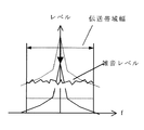
このOFDM方式は、ほぼ、伝送帯域一杯に、一定の周波数間隔で配置された数百本の搬送波を、一定のシンボル周期Ts’でデジタル変調して伝送する方式である。そのため、OFDM信号の波形はランダム雑音に類似した波形になる。その周波数分布も、図11に模式的に示す様に、伝送帯域幅全体に平坦に広がる形状になり、伝送帯域の利用効率が極めて高い方式である。しかしそのために、逆に受信アンテナの方向調整が非常に困難になる欠点がある。
上記した従来のアナログFPUの受信アンテナの方向調整で、単純なスペクトラムアナライザが利用できたのは、アナログFPUが雑音に弱く、高い送信電力で送信していたためだけではなく、変調に用いているFM方式が、伝送帯域利用効率の低い変調方式であったためでもある。
【0004】
図12は、このFM方式で変調された信号の周波数分布を模式的に示したものであるが、高いピークを形成する搬送波を中心に、その両側に急激に減少しながら広がる分布になっている。図中に破線で示すレベルは、送信電力が伝送帯域内全体に平坦に広がると仮定して算出される平均電力レベルである。 図12から分かるように、FM信号の送信電力は搬送波に集中し、搬送波は破線の平均電力レベルに比べて、極めて高いピークレベルを有している。そのため、受信アンテナの方向が最適な方向から大きくずれている方向調整の初期段階において、受信信号のレベルが極めて低く、平均電力レベルが雑音の下に隠れている場合でも、図13の様に、搬送波のピークレベルを測定することが可能である。そのため、全く復調できない受信アンテナの方向調整の初期段階から、受信アンテナの方向と受信レベルの関係を測定することができ、容易に受信アンテナの方向を調整することができた。
これに対しOFDM方式では、図11のように、ほぼ平均電力レベルに等しい平坦な分布になる。しかもOFDM方式の伝送装置では、例えば各搬送波を変調する変調方式としてBPSKを採用し、符号化率1/2の畳み込み符号を用いて伝送すると、C/Nが約0dBでも受信可能である。この状態では、受信信号のレベルと雑音のレベルがほぼ等しくなるが、受信信号の電力と雑音の電力の和からなる伝送帯域内の信号の電力密度は、図14のように、その外側の雑音のみの電力レベルに対して3dB程度高くなる。 従って、スペクトラムアナライザを用いる方法でも、最適な方向に受信アンテナを向ければ、何とか伝送信号の存在を確認することができる。
【0005】
しかし、図13の場合と同じように、受信アンテナの方向が大きくずれると、OFDM信号のレベルは、図15のように雑音の下に完全に埋もれ、目で見てもその存在すら確認できなくなる。送信場所が見える近距離の伝送であれば、感に頼って方向調整を実施することも可能である。しかし伝送距離が数キロを越えると、GPS等を利用して、送信場所と受信場所の正確な位置関係を測定しなければ、受信アンテナの方向調整は事実上不可能になる。
本発明はこれらの欠点を除去し、OFDM方式の受信装置において、C/Nが約0dB以下になる受信アンテナの方向調整の初期段階でも、受信信号のレベルを検出することができ、受信アンテナの方向調整可能としたシステムを提供することを目的とする。
【0006】
【課題を解決するための手段】
本発明は上記目的を達成するため、ガード期間を含んだOFDM信号を伝送する伝送装置の受信装置において、受信した上記OFDM信号のガード期間における相関演算を行い、当該相関演算の結果得られるガード相関信号に基づき受信アンテナの方向調整用信号を生成し、該受信アンテナの方向調整を行うようにしたものである。
また、ガード期間を含んだOFDM信号を伝送する伝送装置の受信装置において、受信信号の上記ガード期間における相関演算を行い、当該相関演算の結果得られるガード相関信号から上記受信信号のレベルを算出し、該受信信号レベルに基づき受信アンテナの方向調整用信号を生成し、該生成した方向調整用信号を用いて受信アンテナの方向調整を行うようにしたものである。
また、上記生成される方向調整用信号を、上記受信信号のレベルに応じて音質、音量、断続間隔の少なくとも1つが変化する方向調整用の音の信号としたものである。
また、上記生成した方向調整用信号のレベルを表示し、これに応じて受信アンテナの方向調整を行うようにしたものである。
また、ガード期間を含んだOFDM信号を伝送する伝送装置の受信装置において、受信信号の上記ガード期間における相関演算を行いガード相関信号を出力するガード相関算出回路と、該ガード相関信号から上記受信信号のレベルを算出して出力する受信レベル算出回路と、該算出した受信信号レベルに基づき受信アンテナの方向調整用信号を生成し出力する方向調整信号発生回路とを有し、該生成した方向調整用信号を用いて受信アンテナの方向調整を行うようにしたものである。
【0007】
また、ガード期間を含んだOFDM信号を伝送する伝送装置の受信装置において、受信信号の上記ガード期間における相関演算を行いガード相関信号を出力するガード相関算出回路と、該ガード相関信号から上記受信信号のレベルを算出して出力する受信レベル算出回路と、該算出した受信信号レベルに基づき受信アンテナの方向調整用信号を生成し出力する方向調整信号発生回路と、該生成した方向調整信号を上記受信アンテナに伝送する伝送系を有するものである。
また、ガード期間を含んだOFDM信号を伝送する伝送システムにおいて、受信信号の上記ガード期間における相関演算を行い、ガード相関信号あるいはその絶対値信号を算出する復調装置から出力される上記ガード相関信号あるいはその絶対値信号を入力する入力端子と、該ガード相関信号あるいはその絶対値信号から上記受信信号のレベルを算出して出力する受信レベル算出回路と、該算出した受信信号レベルに基づき受信アンテナの方向調整用信号を生成し出力する方向調整信号発生回路と、該生成した方向調整信号を出力する出力端子を有する受信アンテナ調整用のアダプタである。
また、ガード期間を含んだOFDM信号を伝送する伝送システムにおいて、受信信号の上記ガード期間における相関演算を行い、ガード相関信号あるいはその絶対値信号を算出し、該ガード相関信号あるいはその絶対値信号に基づき上記受信信号のレベルを算出する復調装置から出力される上記受信信号レベルを入力する入力端子と、該受信信号レベルに基づき受信アンテナの方向調整用信号を生成し出力する方向調整信号発生回路と、該生成した方向調整信号を出力する出力端子を有する受信アンテナ調整用のアダプタである。
【0008】
また、上記受信レベル算出回路を、上記ガード相関信号の絶対値のピーク位置を検出し、当該検出したピーク位置におけるガード相関信号の複素ベクトル信号としての絶対値のピーク値、その二乗値、該ピーク値の平方根値、該ピーク値とその二乗値と平方根値の何れかの値の平均値のいずれか1つを受信レベル信号として出力する回路としたものである。
また、上記方向調整信号発生回路を、上記受信レベル信号自身、該受信信号の実効値にほぼ比例する信号、該受信信号の電力値にほぼ比例する信号、該受信信号のdB値(対数値)にほぼ比例する信号、該受信信号の受信レベルに応じた高さまたは断続間隔の音の信号、該受信信号の受信レベルに応じた明るさまたは色または表示バーの長さ等のメータ表示値を制御する信号、上記受信アンテナの方向を調整する雲台の方向を制御する制御信号の内のいずれか1つの信号を方向調整信号として出力する回路としたものである。
また、上記ガード相関信号、その絶対値信号、上記受信レベル信号、上記方向調整信号の何れか1つの信号波形とともに、これらの信号の最大レベルあるいは最小レベルあるいは上記受信信号を正しく復調できる限界レベルの内の少なくとも1つのレベルを表示するようにしたものである。
【0009】
【発明の実施の形態】
本発明の伝送装置における受信アンテナ方向調整システムの第1の実施例による構成例を図1に示し、受信側を中心にして説明する。
送信装置12の送信前処理回路13aに入力された情報符号は、誤り訂正符号への変換、64QAMへの変調等の前処理により、各搬送波の信号を表す周波数分布イメージの信号列に変換され、逆フーリエ変換(IFFT)回路13bで時間波形を表す信号列に変換される。そしてガードインターバル挿入回路13cで、後述の様に、伝送路での遅延波に起因する受信側での符号間干渉の影響を少なくするため、送信されるOFDM信号にガードインターバルが付加される。 このガードインターバルを挿入された信号は、送信後処理回路13dにおいてさらに直交変調、D/A変換、アップコンバート等の後処理を施された後、送信アンテナ11から送信される。
この送信されたOFDM伝送信号は、受信アンテナ1で受信され、ケーブルを通して復調装置2に送られる。 復調装置2に入力された受信信号は、ダウンコンバータ3a、A/D変換回路3bでディジタルの複素ベクトル信号に変換された後、伝送された情報符号を復調する信号処理を実施するFFT(フーリエ変換)回路3c、伝送路応答等化回路3d、復調&復号回路3e等からなる本線系の経路に入力されるとともに、別経路にあるガード相関算出回路4に入力される。
【0010】
このガード相関算出回路4では、シンボル期間の境界点を検出する方法として特開平7−099486号公報に開示されている演算と類似の演算を実施する。本発明の方法では、全てこのガード相関算出回路4で算出されるガード相関信号Cgが出発点となるので、初めにこの回路で実施する信号処理をやや詳しく説明しておく。
ところで、上記したように、OFDM方式は、一定の周波数間隔で配置された数百本の搬送波(キャリア)を、それぞれ一定のシンボル期間Ts’でデジタル変調して伝送する方式である。OFDM信号への変調には、通常、ポイント数M(例えば、M=2048)のIFFT(逆フーリエ変換)が用いられる。送信側から送出される伝送信号の1シンボルは、図2に模式的に示すように、このIFFTで変調された、MポイントのOFDM信号からなる有効シンボル期間Tsの信号(B+b)と、1シンボルの最後のMg(例えばMg=128)ポイント期間Tg’の信号bを有効シンボル期間Ts前のガード期間Tgに複写したMgポイントのガードインターバル信号b’で構成される。なお、aとa’の部分、cとc’の部分についても同様である。
【0011】
以上の知識を基に、図1のガード相関算出回路4で実施される処理を、図3の回路例を用いて説明する。A/D変換回路3bでサンプリングされ、ガード相関算出回路4に入力された複素ベクトル信号Zin(m)は2つに分岐され、その一方は遅延回路41に入力され、図4(a)の下段の信号の様に、有効シンボル期間Tsに相当するサンプリング数M(例えばM=2048)だけ遅延される。ここで、mはサンプル点の番号である。
図1のA/D変換回路3bでは、送信装置12のIFFTで用いられるクロック周波数と同じ周波数のクロックを用いてサンプリングするので、有効シンボル期間Tsのサンプル点数は、IFFTのポイント数Mに等しくなる。
この有効シンボル期間Tsだけ遅延された信号Zin(m−M)と、遅延前の信号Zin(m)は、複素乗算回路42でサンプル点毎に複素乗算され、
Zmul(m)=Zin(m)×Zin(m−M)* ・・・・・・・・・・・(1)
が算出される。この複素乗算信号の波形を、図4(b)に模式的に示す。
ここで、同じ信号であるbとb’を乗算する範囲の値は|b(m)|2+j・0となり、図4の期間21のように、正の実数値になる。なお、OFDM信号は、ランダム雑音に近い波形であり、その振幅値である|b(m)|2の値もランダムに振動する。そのため、正確には、図4の期間21のI成分(実数成分)のレベルもランダムに振動する。しかし後述する雑音の影響との混同を避けるため、ここでは直線を用いて模式的に示した。
【0012】
一方、図4の期間22の様に、C×B*等、互いに異なる複素ベクトル信号を乗算する期間の複素乗算信号は、ランダムなままの波形(但し振幅が二乗された波形)になる。
図3の複素乗算回路42から出力された複素ベクトル信号Zmul(m)は、相関演算回路43内のシフトレジスタに順次入力され、下記(2)式に示すように、各サンプル点毎に、シフトレジスタ内のMgサンプルの信号の加算演算、
Cg(m)=ΣZmul(m−k) (但し、k=0〜Mg−1) ・・・・(2)
を実施し、ガード相関信号Cgとして出力する。図4(c)は、このガード相関信号Cgの波形を模式的に示したものである。
サンプル点23では、加算する信号がランダムに変化するMgサンプルの信号であるため、互いに打ち消し合いレベルが比較的小さくランダムな信号になる。これに対し、サンプル点24では加算する信号が全て同じ信号bとb’同士の乗算値|b(m)|2+j・0になる。そのためI成分では、Mg個の正の実数値が、互いに打ち消し合うことなく全て加算されるようになり、図4(c)の太い矢印で示す様に、大きな正の実数値の信号になる。また、Q成分では、加算すべき値が全て0に成るため、加算結果も0に成る。
【0013】
サンプル点25の様にサンプル点24から少しずれると、加算する正の実数値の数が減り、代わりに互いに打ち消し合うランダムな信号の数が増加する。そのため、I成分のレベルは徐々に小さくなる。また、Q成分の値は逆に徐々に増大し、ランダムに振動する信号になる。
そのため、図1のガード相関算出回路4から出力されるガード相関信号Cgは、図4(c)の様に、I成分はシンボル期間の境界点でピークを持つほぼ三角形の波形になり、Q成分は逆に境界点でほぼ0に成る波形になる。
なお、以上の説明は、受信装置のLo周波数(局部発振周波数)の同期が引き込まれた場合にのみ成り立つ。受信アンテナの方向調整の初期段階のように同期が確立されていない時は、図4(c)のI成分とQ成分で構成される複素ベクトル信号は、任意の方向に回転された信号になる。
【0014】
図1のガード相関算出回路4から出力されたガード相関信号Cgは、受信信号のレベルを算出するために、受信レベル算出回路5に入力される。図5は、この受信レベル算出回路5の内部回路の例を示したものである。
受信レベル算出回路5に入力されたガード相関信号Cgは、図5のピーク点検出回路51に入力され、ここで1シンボル期間Ts’毎に、ガード相関信号Cgの複素ベクトル信号としての絶対値の、そのシンボル期間内におけるピーク点が検出される。検出されたピーク位置を表すピーク位置信号とガード相関信号Cgは、I成分絶対値のピーク点値算出回路52とQ成分絶対値のピーク点値算出回路53に入力される。
そして、それぞれの回路で、検出したピーク点における、ガード相関信号CgのI成分の絶対値|maxIc|とQ成分の絶対値|maxQc|を算出した後、ピーク点値加算回路54でそれらの加算値|maxIc|+|maxQc|を算出する。
これはガード相関信号Cgの複素ベクトル信号としての絶対値の近似値を算出する演算で、正確な絶対値max|Cg|=√(maxCg×maxCg*)を算出するのが好ましい。ここで、maxCgはガード相関信号Cgのピーク点における値(複素ベクトル信号)である。
【0015】
ところで、受信アンテナの方向が最適な方向に向けられているときは、受信信号のレベルが大きく、雑音を無視することができるので、OFDM信号のみからなる信号が得られると近似できる。そのため、ピーク値max|Cg|は、

通常、Mgの値は約128サンプルあるいはそれ以上の大きな正数であるため、ガード相関算出回路4に入力されるOFDM信号の平均電力をσ2とすると、ピーク値max|Cg|は、値Mg×σ2に近い値、すなわち平均電力σ2にほぼ比例した値になる。
【0016】
一方、受信アンテナの方向が誤った方向に向けられているときは、OFDM信号を殆ど受信できず、極端な場合、ガード相関算出回路4に入力される信号は、殆ど雑音のみになる。この場合、複素乗算するZin(m)とZin(m−M)*の間には相関が無くなるため、Zmul(m)は、ガード相関算出回路4に入力される雑音の電力σn2にほぼ等しい実効値を持つ、ランダムな信号になる。そのため、Mgサンプル分のZmul(m)を加算すると、極性が逆の値同士が打ち消し合い、ガード相関信号Cg(m)は、ほぼσn2×√Mg程度の実効値を持つランダムな信号になる。
【0017】
また、受信アンテナの方向調整の途中では、無視できないレベルの雑音が混入したOFDM信号がガード相関算出回路4に入力されるが、この場合に算出されるピーク値max|Cg|は、入力されるOFDM信号成分の電力σ2に比例する値Mg×σ2を有する信号に、混入している雑音成分の電力σn2に比例した実効値σn2×√Mgを持つランダムな信号が加算された信号になる。
従って、受信信号のCN比がσ/σnの場合、
SN比 (Mg×σ2)/(σn2×√Mg)=(σ/σn)2×√Mg
のOFDM信号のピーク値が得られる。例えばガードインターバルの長さMgが128サンプルの場合、受信信号のCN比が0dB=20・log(σ/σn)であっても、
【0018】
図5の平均化回路55は、得られるピーク値のSN比をさらに上げるために、ピーク点値加算回路54からシンボル毎に出力されるピーク値max|Cg|の平均値を算出する回路である。具体的には、一定数のピーク値max|Cg|の加算平均を算出する回路またはシンボル毎に入力されるピーク値max|Cg|の帯域を制限するLPF(ローパスフィルタ)を用いれば良い。例えば、64シンボルのピーク値max|Cg|の加算平均を算出するだけで、SN比をさらに、10・log(64)=18dB改善することができる。この平均化の演算には、この他、上記した値|b(m)|2のランダムな振動の影響で発生する、ピーク値のランダムな変動を低減する効果も得られる。
【0019】
ところで、以上の演算で算出されるピーク値max|Cg|は、ガード相関算出回路4に入力される信号Zinに含まれるOFDM信号成分の電力σ2に比例する値であり、必ずしも受信した信号の電力レベルPsに比例しない。通常、受信装置では、受信条件で大きく変化する受信信号のレベルをAGC回路でほぼ一定レベルの信号に変換してから、各種の信号処理を実施する。ガード相関算出回路4に入力される信号Zinの電力も、常にほぼ一定に保たれる。
【0020】
従って、受信されるOFDM信号のレベルが大きい時は、ガード相関算出回路4に入力されるOFDM信号の電力レベルσ2がほぼ一定になるように制御されてしまい、受信レベル算出回路5で算出されるピーク値max|Cg|の大きさも、ほぼ一定になる。そのため通常は、算出したピーク値max|Cg|から、受信されたOFDM信号の正確な電力レベルPsを検出することはできない。
しかし、実際にAGC回路で制御される信号は、受信された電力レベルPsのOFDM信号と混入された電力レベルPnの雑音からなる信号全体の電力レベルPtot=Ps+Pnである。そのため、ガード相関算出回路4に入力される信号Zinに含まれるOFDM信号の電力レベルは、正確には、
σ2=Ps/Ptot=(Ps/Pn)×1/(Ps/Pn+1) となる。
【0021】
一方、受信アンテナの方向調整において、受信信号のレベルの検出が最も重要になるのは、受信アンテナの方向がずれ、受信されるOFDM信号の電力レベルPsが減少し、受信装置のヘッドAMPで発生する雑音の電力レベルPnの方が大きくなった時である。
このように、OFDM信号の電力レベルPsより雑音の電力レベルPnの方が充分大きくなると、Ps/Pn+1≒1の近似が成り立つ様になり、ガード相関算出回路4に入力されるOFDM信号の電力レベルは、σ2≒Ps/Pnと近似できるようになる。ここで、ヘッドAMPで発生する雑音の電力レベルPnは、受信装置の回路の性能で決まる一定値なので、結局、ガード相関算出回路4に入力されるOFDM信号の電力レベルσ2は、受信されたOFDM信号の電力レベルPsにほぼ比例した値になる。従って、受信レベル算出回路5で算出したピーク値max|Cg|も、受信されたOFDM信号の電力レベルPsにほぼ比例した値になり、そのレベルを検出することができる。
しかも、上記した様に、ピーク値max|Cg|は、約21dB+18dB=39dBもの高SN比の値である。そのため、受信アンテナの方向が誤った方向に向けられ、受信されるOFDM信号の電力レベルが、図15の様に雑音レベルより20dB程度以上低下しても、その信号の存在だけでなく、そのレベル変化をも検出することができる。
【0022】
そこで、受信レベル算出回路5からは、このようにして算出され平均化されたピーク値max|Cg|を、受信レベル信号として出力する。
受信レベル算出回路5から出力された受信レベル信号は方向調整信号発生回路6に入力され、受信アンテナ1の調整に適した信号に変換され、方向調整信号として出力される。
この方向調整信号としては、例えば受信アンテナ1の調整を実施するときは、受信アンテナの調整者が調整し易いように、受信レベルが高いほど高音になる、あるいは受信レベルが高いほど間隔が狭くなる断続音等のビープ音を発生させる方向調整信号を出力するようにする。
あるいは、オシロスコープ等でその電圧変化を観察しながらレベルが最大になるように調整する等、受信レベルを測定しながら受信アンテナの方向を調整する場合は、受信レベル信号の値を、調整が容易になる単位系の値、例えばdB値等の値に変換して得た信号を、方向調整信号として出力するようにする。
あるいは、受信レベルを表示するメータを用い受信レベルを測定しながら受信アンテナの方向を調整する場合は、受信レベルに応じた明るさ、色または表示バーの長さ等のメータ表示値を制御する信号を、方向調整信号として出力するようにする。
あるいは、受信アンテナの雲台を小さく動かした時に、受信レベルが増加するときは、更に同じ方向に移動し、減少するときは反対方向に動かすことにより、最適な方向に受信アンテナを制御する方法を用いる場合は、受信レベル信号の値を雲台の制御が容易になる単位系の値に変換して得た信号を、方向調整信号として出力するようにする。勿論、雲台の制御信号を方向調整信号として出力するようにしても良い。
このように、本実施例によるOFDM方式の復調装置を用いると、受信されるOFDM信号のCN比が0dB以下になり、従来と同じ方法、即ちスペクトラムアナライザを用いる方法では、OFDM信号の存在すら検出できないような受信アンテナの方向調整の初期段階においても、OFDM信号の存在を検出できるようになるだけでなく、受信されたOFDM信号の電力レベルとその変化量を、高SN比で測定することができるようになる。
そのため、受信アンテナの方向を変えながら、受信されるOFDM信号レベルが最大になる方向を探すことができるようになり、算出した受信レベル信号を用いて、容易に受信アンテナの方向調整ができるシステムを構築することができるようになる。
【0023】
次に、本発明の第2の実施例による受信装置のシステム構成例を図6に示す。このシステム構成は、受信レベル算出回路5と方向調整信号発生回路6を、復調装置2’の外部のアダプタ7として分離した点が、第1の実施例と異なる。
OFDM方式の復調装置では、シンボルの境界位置の同期を検出するために、通常、ガード相関算出回路4と同じ機能を持つガード相関演算回路4’を有している。本実施例によるシステムでは、この復調装置2’が通常有しているガード相関演算回路4’から出力されるガード相関信号Cgまたはその絶対値|Cg|を利用する。
そのため、本実施例の復調装置2’では、従来の復調装置に、新たにガード相関信号Cgあるいはその絶対値|Cg|を出力する出力端子を設けておくだけでよい。
受信アンテナ1の方向調整を実施する時は、ガード相関信号Cgあるいはその絶対値|Cg|を入力する端子と、方向調整信号発生回路6から出力される方向調整信号を出力する端子を有するアダプタ7を別に用意する。これ以外の回路構成は第1の実施例と同一なので、説明を省略する。
この様に、本実施例によるシステムにおいても、第1の実施例と同様に、受信されるOFDM信号のCN比が0dB以下になっても、受信信号の電力レベルとその変化量を高SN比で測定することができるようになり、受信アンテナの方向を変えながら、受信信号のレベルが最大になる方向を探すことができるようになる。また、本実施例によるシステムでは、従来の復調装置に、ガード相関信号を出力できる端子を新たに設ける小改造を施すだけで良い。
そのため、既にOFDM方式の復調装置を所有しているユーザも、新たに高価な復調装置に買い換えることなく、比較的安価なアダプタを購入するだけで、受信アンテナの方向調整が容易になるシステムを構築することができるようになる効果が得られる。
【0024】
なお、第2の実施例における復調装置2’と外部アダプタ7の分離方法としては、図7の様に、方向調整信号発生回路6のみを、復調装置2’の外部アダプタ7として分離するようにしても、ほぼ同様の効果が得られる。
また、受信レベル算出回路5において、ピーク点におけるガード相関信号Cgの正確な絶対値max|Cg|=√(maxCg×maxCg*)を算出するには、maxCg×maxCg*によって、|maxCg|2を算出した後、その平方根を算出することになる。
しかし、この平方根の算出を省略し、算出した|maxCg|2をそのまま受信レベル信号として出力するようにしても良い。但しこの場合、受信レベル信号のレベルが第1の実施例の受信レベル信号の二乗になっていることを考慮して、方向調整信号への変換を実施する必要がある。
また、ピーク点におけるガード相関信号Cgの絶対値を算出する際は、前もってガード相関信号Cgをシンボル内で平均化し、図4(c)の波形を滑らかにした後、算出するようにしても良いのは明らかである。
また、方向調整信号発生回路6で算出される方向調整信号は、受信レベル信号max|Cg|そのものでも良いが、そのほか、受信レベル信号の平方根である√(max|Cg|)、受信信号dB値に比例する10×log(max|Cg|)等、他の単位系の値であっても良いのは言うまでもない。
【0025】
また上記したように、ガード相関算出回路4に入力されるOFDM信号の電力レベルは、1/(Ps/Pn+1)の式で特徴付けられる飽和特性を示すが、この飽和特性を補正した信号を算出するようにすることが好ましいのは言うまでもない。
また、図1の第1の実施例においても、第2の実施例と同様、シンボルの境界位置の同期を検出するためのガード相関演算回路から出力されるガード相関信号Cgを利用するようにしても良いのは、明らかである。
また、受信アンテナの方向調整では、ガード相関信号をそのまま受信アンテナ部に伝送する伝送系を設ければ、受信アンテナ部でオシロスコープ等の表示装置で図4(c)のI成分の波形に類似したガード相関波形を観察しながら方向調整を実施することができる。
また、ガード相関信号あるいは方向調整信号あるいは受信レベル信号の波形を表示させながら受信アンテナの方向を調整する時は、例えば図8に示すように、表示する信号の最大値あるいは最小値あるいはその両方が同時に表示されるようにするのが好ましい。あるいは図9のように、情報符号を正しく復調できる限界レベルが同時に表示されるようにするのが好ましい。
【0026】
また、図8あるいは図9の様に、最大値と最小値あるいは更に復調できる限界レベルの内の少なくとも何れか1つのレベルを表示できるようにするには、これらのレベルを表す信号を別に送る様にしても良い。しかし、図10に例示する様に、ガード相関信号、方向調整信号あるいは受信レベル信号の波形の間に、一定周期毎に、最大レベル、最小レベルあるいは復調できる限界レベルを表す信号を挿入しておくのが好ましい。一般に電気信号は、ケーブル等で長距離伝送すると信号の大きさ(Gain)や直流レベルが変化する現象が起こる。しかし、図10の様に基準となるレベルの信号も同時に伝送する様にすると、伝送の過程で信号のGainや直流レベルが変化しても、同時に伝送した基準レベルを用いることで、正しいレベルの信号を容易に再生することができる効果が得られる。
【0027】
また、図4(c)の説明で述べたように、ガード相関信号Cgのピーク点ではOFDM信号のQ成分はほぼ0になる。そのため、ガード相関算出回路4に入力される信号Zinに雑音が混入している場合、このピーク点のQ成分の絶対値を加算する等の方法で、混入している雑音のレベルを独立に算出することができる。そこで、このQ成分から算出した雑音を利用して、例えばガード相関信号Cgの絶対値max|Cg|と上記のQ成分から算出した雑音レベルとの比を算出する等の方法で受信レベルを算出することができる。受信アンテナの方向調整の初期段階のように同期が確立されていない時は、図4(c)のI成分とQ成分で構成される複素ベクトルが、位相空間上の任意の方向に回転された信号になるため、座標変換等の複雑な演算が必要になるものの、更に精度の高い受信レベル信号を得ることができる。
【0028】
【発明の効果】
以上説明した本発明による手段を用いると、受信されるOFDM信号のCN比が0dB以下になり、従来と同じ方法、即ち、スペクトラムアナライザを用いる方法ではOFDM信号の存在すら検出できないような受信アンテナの方向調整の初期段階においても、OFDM信号の存在を検出できるようになるだけでなく、受信されたOFDM信号の電力レベルとその変化量を、高SN比で測定することができるようになる。そのため、受信アンテナの方向を変えながら、受信されるOFDM信号のレベルが最大になる方向を探すことができるようになり、算出した受信レベル信号を用いて、容易に受信アンテナの方向調整ができるシステムを構築することができるようになる。
【図面の簡単な説明】
【図1】第1の実施例のシステム構成の例
【図2】OFDM信号の構造の説明図
【図3】ガード相関算出回路の回路構成の例
【図4】ガード相関算出回路で実施する演算の説明図
【図5】受信レベル算出回路の回路構成の例
【図6】第2の実施例のシステム構成の例
【図7】第2の実施例に関わる別のシステム構成の例
【図8】第1の表示例
【図9】第2の表示例
【図10】信号の波形例
【図11】OFDM信号の周波数分布の説明図
【図12】従来のアナログFPUで用いるFM信号の周波数分布の説明図
【図13】アナログFPUの受信アンテナの方向調整時の周波数分布の説明図
【図14】OFDM信号を受信している時の周波数分布の説明図
【図15】OFDM方式の受信装置の受信アンテナの方向調整時の周波数分布の説明図
【符号の説明】
1:受信アンテナ、2:復調装置、3:A/D変換回路、4:ガード相関算出回路、4’:ガード相関演算回路、5:受信レベル算出回路、6:方向調整信号発生回路、7:アダプタ、41:遅延回路、42:複素乗算回路、43:相関演算回路、51:ピーク点検出回路、52:I成分絶対値のピーク点値算出回路、53:Q成分絶対値のピーク点値算出回路、54:ピーク点値加算回路、55:平均化回路。[0001]
BACKGROUND OF THE INVENTION
The present invention relates to direction adjustment of a receiving antenna in a transmission apparatus using an orthogonal frequency division multiplex modulation scheme (hereinafter referred to as an OFDM scheme).
[0002]
[Prior art]
Conventionally, when adjusting the direction of the reception antenna of an analog FPU (Field Pickup Unit) to the best direction that maximizes the reception level, the reception signal output from the reception antenna is input to the spectrum analyzer, and the direction of the reception antenna is changed. The method of measuring the level of the carrier wave displayed as a sharp peak on the spectrum analyzer while moving it up and down, left and right, and searching for the direction in which the peak level becomes maximum has been taken.
[0003]
[Problems to be solved by the invention]
By the way, in recent years, in the field of wireless equipment, the OFDM method has attracted attention as a modulation method that is strong against multipath fading, and many applied researches in the fields of next-generation television broadcasting, FPU, wireless LAN, etc. in countries such as Europe and Japan. Is underway. Among them, the development trend and method of terrestrial digital broadcasting in the UHF band are described in 1998, Vol. 52, no. 11 is described in detail.
This OFDM system is a system in which several hundreds of carriers arranged at a constant frequency interval are digitally modulated at a constant symbol period Ts ′ and transmitted over the entire transmission band. Therefore, the waveform of the OFDM signal is similar to random noise. As schematically shown in FIG. 11, the frequency distribution also has a shape that spreads flatly over the entire transmission bandwidth, and is an extremely high transmission band utilization efficiency. However, on the contrary, there is a drawback that the direction adjustment of the receiving antenna becomes very difficult.
In the above-described conventional analog FPU receiving antenna direction adjustment, a simple spectrum analyzer can be used not only because the analog FPU is vulnerable to noise and transmitting with high transmission power, but also for FM used for modulation. This is also because the method was a modulation method with low transmission band utilization efficiency.
[0004]
FIG. 12 schematically shows the frequency distribution of the signal modulated by the FM method, and the distribution is widened while rapidly decreasing on both sides of the carrier wave forming a high peak. . The level indicated by a broken line in the figure is an average power level calculated on the assumption that the transmission power spreads flatly throughout the transmission band. As can be seen from FIG. 12, the transmission power of the FM signal is concentrated on the carrier wave, and the carrier wave has a very high peak level compared to the average power level of the broken line. Therefore, even when the level of the received signal is extremely low and the average power level is hidden under noise at the initial stage of direction adjustment in which the direction of the receiving antenna is greatly deviated from the optimum direction, as shown in FIG. It is possible to measure the peak level of the carrier wave. Therefore, the relationship between the direction of the receiving antenna and the reception level can be measured from the initial stage of the direction adjustment of the receiving antenna that cannot be demodulated at all, and the direction of the receiving antenna can be easily adjusted.
On the other hand, in the OFDM method, as shown in FIG. 11, a flat distribution almost equal to the average power level is obtained. Moreover, in an OFDM transmission apparatus, for example, when BPSK is adopted as a modulation scheme for modulating each carrier wave and transmission is performed using a convolutional code with a coding rate of 1/2, reception is possible even with a C / N of about 0 dB. In this state, the level of the received signal is almost equal to the noise level, but the power density of the signal within the transmission band, which is the sum of the power of the received signal and the noise, is outside the noise as shown in FIG. Only about 3 dB higher than the power level. Therefore, even with a method using a spectrum analyzer, the presence of a transmission signal can be confirmed somehow if the receiving antenna is pointed in an optimum direction.
[0005]
However, as in the case of FIG. 13, when the direction of the receiving antenna is greatly deviated, the OFDM signal level is completely buried under noise as shown in FIG. 15, and even its presence cannot be confirmed visually. . If it is a short-distance transmission where the transmission location can be seen, it is possible to adjust the direction depending on the feeling. However, when the transmission distance exceeds several kilometers, the direction adjustment of the receiving antenna becomes practically impossible unless the exact positional relationship between the transmitting location and the receiving location is measured using GPS or the like.
The present invention eliminates these drawbacks, and can detect the level of the received signal even in the initial stage of the direction adjustment of the receiving antenna where the C / N is about 0 dB or less in the OFDM receiver. An object is to provide a system capable of adjusting the direction.
[0006]
[Means for Solving the Problems]
In order to achieve the above object, the present invention performs a correlation calculation in the guard period of the received OFDM signal in a receiving apparatus of a transmission apparatus that transmits an OFDM signal including a guard period, and obtains a guard correlation obtained as a result of the correlation calculation. A signal for adjusting the direction of the receiving antenna is generated based on the signal, and the direction of the receiving antenna is adjusted.
Further, in a receiving apparatus of a transmission apparatus that transmits an OFDM signal including a guard period, a correlation calculation is performed on the received signal in the guard period, and a level of the received signal is calculated from the guard correlation signal obtained as a result of the correlation calculation. The direction adjustment signal of the reception antenna is generated based on the reception signal level, and the direction adjustment of the reception antenna is performed using the generated direction adjustment signal.
Further, the generated direction adjustment signal is a direction adjustment sound signal in which at least one of sound quality, volume, and intermittent interval changes according to the level of the received signal.
Further, the level of the generated direction adjustment signal is displayed, and the direction of the receiving antenna is adjusted accordingly.
Further, in a receiving apparatus of a transmission apparatus that transmits an OFDM signal including a guard period, a guard correlation calculation circuit that performs a correlation operation in the guard period of the received signal and outputs a guard correlation signal, and the received signal from the guard correlation signal A reception level calculation circuit that calculates and outputs a level of the signal, and a direction adjustment signal generation circuit that generates and outputs a direction adjustment signal of the reception antenna based on the calculated reception signal level, and for the generated direction adjustment The direction of the receiving antenna is adjusted using the signal.
[0007]
Further, in a receiving apparatus of a transmission apparatus that transmits an OFDM signal including a guard period, a guard correlation calculation circuit that performs a correlation operation in the guard period of the received signal and outputs a guard correlation signal, and the received signal from the guard correlation signal A reception level calculation circuit that calculates and outputs a level of the signal, a direction adjustment signal generation circuit that generates and outputs a direction adjustment signal for the reception antenna based on the calculated reception signal level, and the reception of the generated direction adjustment signal It has a transmission system for transmitting to an antenna.
Further, in a transmission system for transmitting an OFDM signal including a guard period, the guard correlation signal or the guard correlation signal output from a demodulator that performs correlation calculation in the guard period of the received signal and calculates a guard correlation signal or an absolute value signal thereof, or An input terminal for inputting the absolute value signal, a reception level calculating circuit for calculating and outputting the level of the received signal from the guard correlation signal or the absolute value signal, and a direction of the receiving antenna based on the calculated received signal level A receiving antenna adjustment adapter having a direction adjustment signal generation circuit that generates and outputs an adjustment signal and an output terminal that outputs the generated direction adjustment signal.
Further, in a transmission system for transmitting an OFDM signal including a guard period, a correlation calculation of the received signal in the guard period is performed, a guard correlation signal or an absolute value signal thereof is calculated, and the guard correlation signal or the absolute value signal is calculated. An input terminal for inputting the received signal level output from a demodulator that calculates the received signal level based on the received signal level; and a direction adjustment signal generating circuit for generating and outputting a direction adjustment signal for the receiving antenna based on the received signal level; A receiving antenna adjustment adapter having an output terminal for outputting the generated direction adjustment signal.
[0008]
Further, the reception level calculation circuit detects the peak position of the absolute value of the guard correlation signal, the peak value of the absolute value as a complex vector signal of the guard correlation signal at the detected peak position, its square value, the peak The circuit outputs one of the square root value of the value, the peak value, the square value thereof, and the average value of any of the square root values as a reception level signal.
In addition, the direction adjustment signal generation circuit includes the reception level signal itself, a signal substantially proportional to the effective value of the reception signal, a signal substantially proportional to the power value of the reception signal, and a dB value (logarithmic value) of the reception signal. Meter display values such as brightness or color or display bar length according to the reception level of the received signal In this circuit, any one of a control signal and a control signal for controlling the direction of the pan head for adjusting the direction of the receiving antenna is output as a direction adjustment signal.
In addition to the signal waveform of any one of the guard correlation signal, its absolute value signal, the reception level signal, and the direction adjustment signal, the maximum level or minimum level of these signals or the limit level at which the received signal can be correctly demodulated At least one of the levels is displayed.
[0009]
DETAILED DESCRIPTION OF THE INVENTION
A configuration example according to the first embodiment of the receiving antenna direction adjusting system in the transmission apparatus of the present invention is shown in FIG.
The information code input to the transmission preprocessing circuit 13a of the
The transmitted OFDM transmission signal is received by the receiving
[0010]
The guard
By the way, as described above, the OFDM scheme is a scheme in which several hundreds of carriers (carriers) arranged at a certain frequency interval are digitally modulated and transmitted at a certain symbol period Ts ′. For the modulation to the OFDM signal, IFFT (Inverse Fourier Transform) with M points (for example, M = 2048) is usually used. As schematically shown in FIG. 2, one symbol of a transmission signal transmitted from the transmission side is a signal (B + b) of an effective symbol period Ts composed of an M-point OFDM signal modulated by the IFFT and one symbol. The last Mg (for example, Mg = 128) point period Tg ′ of the signal b is copied to the guard period Tg before the effective symbol period Ts, and is composed of the Mg point guard interval signal b ′. The same applies to the parts a and a ′ and the parts c and c ′.
[0011]
Based on the above knowledge, the processing performed by the guard
In the A / D conversion circuit 3b of FIG. 1, sampling is performed using a clock having the same frequency as the clock frequency used in the IFFT of the
The signal Zin (m−M) delayed by the effective symbol period Ts and the signal Zin (m) before the delay are complex-multiplied for each sample point by the complex multiplier circuit 42.
Zmul (m) = Zin (m) × Zin (m−M) * ・ ・ ・ ・ ・ ・ ・ ・ ・ ・ ・ (1)
Is calculated. The waveform of this complex multiplication signal is schematically shown in FIG.
Here, the value of the range in which the same signal b and b ′ are multiplied is | b (m) | 2 + J · 0, which is a positive real value as in the period 21 in FIG. The OFDM signal has a waveform close to random noise, and its amplitude value | b (m) | 2 The value of also vibrates randomly. Therefore, precisely, the level of the I component (real number component) in the period 21 in FIG. 4 also vibrates randomly. However, in order to avoid confusion with the influence of noise, which will be described later, here, it is schematically shown using a straight line.
[0012]
On the other hand, as in the period 22 in FIG. * The complex multiplication signal during a period of multiplying different complex vector signals, for example, has a random waveform (however, the amplitude is squared).
The complex vector signal Zmul (m) output from the complex multiplication circuit 42 in FIG. 3 is sequentially input to the shift register in the correlation calculation circuit 43, and is shifted at each sample point as shown in the following equation (2). Addition operation of Mg sample signal in register,
Cg (m) = ΣZmul (m−k) (where k = 0 to Mg−1) (2)
And output as a guard correlation signal Cg. FIG. 4C schematically shows the waveform of the guard correlation signal Cg.
At the sample point 23, since the signal to be added is an Mg sample signal that changes at random, the levels cancel each other out and become random signals. On the other hand, at the sampling point 24, the multiplication values | b (m) | 2 + J · 0. Therefore, in the I component, all the Mg positive real values are added without canceling each other, resulting in a large positive real value signal as shown by the thick arrow in FIG. In the Q component, all the values to be added are 0, so the addition result is also 0.
[0013]
A slight deviation from the sample point 24, such as the
Therefore, as shown in FIG. 4C, the guard correlation signal Cg output from the guard
The above description is valid only when the synchronization of the Lo frequency (local oscillation frequency) of the receiving device is drawn. When synchronization is not established as in the initial stage of receiving antenna direction adjustment, the complex vector signal composed of the I component and the Q component in FIG. 4C is a signal rotated in an arbitrary direction. .
[0014]
The guard correlation signal Cg output from the guard
The guard correlation signal Cg input to the reception
Then, the absolute value | maxIc | and the absolute value | maxQc | of the I component of the guard correlation signal Cg at the detected peak point are calculated by the respective circuits, and then added by the peak point value adding circuit 54. The value | maxIc | + | maxQc | is calculated.
This is an operation for calculating an approximate value of an absolute value as a complex vector signal of the guard correlation signal Cg, and an accurate absolute value max | Cg | = √ (maxCg × maxCg * ) Is preferably calculated. Here, maxCg is a value (complex vector signal) at the peak point of the guard correlation signal Cg.
[0015]
By the way, when the direction of the receiving antenna is directed to the optimum direction, the level of the received signal is large and noise can be ignored, so that it can be approximated that a signal consisting only of the OFDM signal is obtained. Therefore, the peak value max | Cg |
Usually, since the value of Mg is a large positive number of about 128 samples or more, the average power of the OFDM signal input to the guard
[0016]
On the other hand, when the direction of the receiving antenna is directed in the wrong direction, the OFDM signal can hardly be received. In an extreme case, the signal input to the guard
[0017]
Further, in the middle of the direction adjustment of the receiving antenna, an OFDM signal mixed with noise of a level that cannot be ignored is input to the guard
Therefore, when the CN ratio of the received signal is σ / σn,
SN ratio (Mg × σ 2 ) / (Σn 2 × √Mg) = (σ / σn) 2 × √Mg
The peak value of the OFDM signal is obtained. For example, when the length Mg of the guard interval is 128 samples, even if the CN ratio of the received signal is 0 dB = 20 · log (σ / σn),
[0018]
The averaging circuit 55 in FIG. 5 is a circuit that calculates an average value of the peak values max | Cg | output from the peak point value adding circuit 54 for each symbol in order to further increase the SN ratio of the obtained peak values. . Specifically, a circuit that calculates an average of a certain number of peak values max | Cg | or an LPF (low-pass filter) that limits the band of the peak value max | Cg | input for each symbol may be used. For example, the SN ratio can be further improved by 10 · log (64) = 18 dB simply by calculating the average of the peak values max | Cg | of 64 symbols. In addition to this, the above-described value | b (m) | 2 It is also possible to obtain an effect of reducing the random fluctuation of the peak value that occurs due to the random vibration of
[0019]
Incidentally, the peak value max | Cg | calculated by the above calculation is the power σ of the OFDM signal component included in the signal Zin input to the guard
[0020]
Therefore, when the level of the received OFDM signal is large, the power level σ of the OFDM signal input to the guard
However, the signal actually controlled by the AGC circuit is the power level Ptot = Ps + Pn of the entire signal composed of the received OFDM signal of the power level Ps and the mixed noise of the power level Pn. Therefore, the power level of the OFDM signal included in the signal Zin input to the guard
σ 2 = Ps / Ptot = (Ps / Pn) × 1 / (Ps / Pn + 1).
[0021]
On the other hand, in the direction adjustment of the receiving antenna, detection of the level of the received signal is most important because the direction of the receiving antenna is shifted, the power level Ps of the received OFDM signal is reduced, and is generated in the head AMP of the receiving apparatus. This is when the power level Pn of the noise to be increased becomes larger.
Thus, when the noise power level Pn is sufficiently higher than the power level Ps of the OFDM signal, an approximation of Ps / Pn + 1≈1 is established, and the power level of the OFDM signal input to the guard
Moreover, as described above, the peak value max | Cg | is a value with a high SN ratio of about 21 dB + 18 dB = 39 dB. Therefore, even if the direction of the receiving antenna is turned to the wrong direction and the power level of the received OFDM signal is reduced by about 20 dB or more from the noise level as shown in FIG. Changes can also be detected.
[0022]
Therefore, the reception
The reception level signal output from the reception
As the direction adjustment signal, for example, when the adjustment of the
Or, when adjusting the direction of the receiving antenna while measuring the reception level, such as adjusting the level to the maximum while observing the voltage change with an oscilloscope etc., it is easy to adjust the value of the reception level signal A signal obtained by converting into a unit system value such as a dB value is output as a direction adjustment signal.
Alternatively, when adjusting the direction of the receiving antenna while measuring the reception level using a meter that displays the reception level, a signal that controls meter display values such as brightness, color, or display bar length according to the reception level Is output as a direction adjustment signal.
Alternatively, when the receiving antenna head is moved small, if the reception level increases, it moves further in the same direction, and when it decreases, it moves in the opposite direction to control the receiving antenna in the optimal direction. When used, a signal obtained by converting the value of the reception level signal into a unit system value that makes it easy to control the camera platform is output as a direction adjustment signal. Of course, the pan head control signal may be output as the direction adjustment signal.
As described above, when the OFDM demodulator according to the present embodiment is used, the CN ratio of the received OFDM signal becomes 0 dB or less, and even the presence of an OFDM signal is detected by the same method as before, that is, the method using a spectrum analyzer. Even in the initial stage of receiving antenna direction adjustment that cannot be performed, not only the presence of the OFDM signal can be detected, but also the power level of the received OFDM signal and its variation can be measured with a high S / N ratio. become able to.
Therefore, it is possible to search for a direction in which the received OFDM signal level becomes maximum while changing the direction of the receiving antenna, and a system that can easily adjust the direction of the receiving antenna using the calculated reception level signal. Will be able to build.
[0023]
Next, FIG. 6 shows a system configuration example of a receiving apparatus according to the second embodiment of the present invention. This system configuration is different from the first embodiment in that the reception
An OFDM demodulator usually has a guard
Therefore, in the
When the direction of the receiving
As described above, in the system according to the present embodiment, similarly to the first embodiment, even when the CN ratio of the received OFDM signal becomes 0 dB or less, the power level of the received signal and the amount of change thereof are set to the high SN ratio. Thus, the direction in which the level of the received signal is maximized can be found while changing the direction of the receiving antenna. Further, in the system according to the present embodiment, it is only necessary to make a small modification to the conventional demodulator by newly providing a terminal capable of outputting a guard correlation signal.
For this reason, a user who already owns an OFDM demodulator can easily adjust the direction of the receiving antenna simply by purchasing a relatively inexpensive adapter without buying a new expensive demodulator. The effect that can be done is obtained.
[0024]
As a method of separating the demodulator 2 'and the
Further, in the reception
However, the calculation of the square root is omitted, and the calculated | maxCg | 2 May be output as a reception level signal. However, in this case, it is necessary to convert to the direction adjustment signal in consideration of the level of the reception level signal being the square of the reception level signal of the first embodiment.
Further, when calculating the absolute value of the guard correlation signal Cg at the peak point, the guard correlation signal Cg may be averaged in advance in the symbol, and the waveform shown in FIG. 4C may be smoothed before calculation. It is clear.
In addition, the direction adjustment signal calculated by the direction adjustment
[0025]
As described above, the power level of the OFDM signal input to the guard
Also in the first embodiment of FIG. 1, similarly to the second embodiment, the guard correlation signal Cg output from the guard correlation calculation circuit for detecting the synchronization of the symbol boundary positions is used. It is clear that it is also good.
In the direction adjustment of the receiving antenna, if a transmission system for transmitting the guard correlation signal to the receiving antenna unit as it is is provided, the receiving antenna unit is similar to the waveform of the I component in the display device such as an oscilloscope in FIG. Direction adjustment can be performed while observing the guard correlation waveform.
Further, when adjusting the direction of the receiving antenna while displaying the waveform of the guard correlation signal, the direction adjustment signal, or the reception level signal, for example, as shown in FIG. It is preferable to display them simultaneously. Alternatively, as shown in FIG. 9, it is preferable that the limit level at which the information code can be correctly demodulated is displayed at the same time.
[0026]
Further, as shown in FIG. 8 or FIG. 9, in order to be able to display at least one of the maximum value and the minimum value or a limit level that can be further demodulated, a signal representing these levels is sent separately. Anyway. However, as illustrated in FIG. 10, a signal representing the maximum level, the minimum level, or the limit level that can be demodulated is inserted between the waveforms of the guard correlation signal, the direction adjustment signal, or the reception level signal at regular intervals. Is preferred. In general, when an electric signal is transmitted over a long distance using a cable or the like, a phenomenon occurs in which the magnitude of the signal (Gain) or the DC level changes. However, if the signal of the reference level is also transmitted simultaneously as shown in FIG. 10, even if the signal gain or DC level changes during the transmission process, the reference level transmitted at the same time is used. The effect that the signal can be easily reproduced is obtained.
[0027]
Further, as described in the explanation of FIG. 4C, the Q component of the OFDM signal is almost zero at the peak point of the guard correlation signal Cg. Therefore, when noise is mixed in the signal Zin input to the guard
[0028]
【The invention's effect】
When the means according to the present invention described above is used, the CN ratio of the received OFDM signal becomes 0 dB or less, and a receiving antenna that cannot detect even the presence of the OFDM signal by the same method as the conventional method, that is, the method using the spectrum analyzer. Even in the initial stage of direction adjustment, not only the presence of the OFDM signal can be detected, but also the power level of the received OFDM signal and its change amount can be measured with a high S / N ratio. Therefore, it is possible to search for a direction in which the level of the received OFDM signal is maximized while changing the direction of the receiving antenna, and a system that can easily adjust the direction of the receiving antenna using the calculated reception level signal. Will be able to build.
[Brief description of the drawings]
FIG. 1 is a system configuration example according to a first embodiment;
FIG. 2 is an explanatory diagram of the structure of an OFDM signal
FIG. 3 shows an example of a circuit configuration of a guard correlation calculation circuit.
FIG. 4 is an explanatory diagram of operations performed by a guard correlation calculation circuit.
FIG. 5 is a circuit configuration example of a reception level calculation circuit;
FIG. 6 shows an example of the system configuration of the second embodiment.
FIG. 7 shows another system configuration example related to the second embodiment.
FIG. 8 shows a first display example
FIG. 9 shows a second display example.
FIG. 10 shows an example of a signal waveform.
FIG. 11 is an explanatory diagram of a frequency distribution of an OFDM signal.
FIG. 12 is an explanatory diagram of frequency distribution of FM signals used in a conventional analog FPU
FIG. 13 is an explanatory diagram of frequency distribution when adjusting the direction of an analog FPU receiving antenna.
FIG. 14 is an explanatory diagram of frequency distribution when receiving an OFDM signal.
FIG. 15 is an explanatory diagram of a frequency distribution when adjusting the direction of a receiving antenna of an OFDM receiver.
[Explanation of symbols]
1: reception antenna, 2: demodulator, 3: A / D conversion circuit, 4: guard correlation calculation circuit, 4 ′: guard correlation calculation circuit, 5: reception level calculation circuit, 6: direction adjustment signal generation circuit, 7: Adapter: 41: Delay circuit, 42: Complex multiplication circuit, 43: Correlation calculation circuit, 51: Peak point detection circuit, 52: Peak point value calculation circuit for I component absolute value, 53: Peak point value calculation for Q component absolute value Circuit: 54: Peak point value adding circuit, 55: Averaging circuit.
Claims (3)
受信した上記OFDM信号と該OFDM信号を有効シンボル遅延した信号と複素乗算し加算することにより、相関演算を行い、当該相関演算の結果得られる信号の絶対値のピーク位置を検出し、当該検出したピーク位置における相関信号のI成分の絶対値とQ成分の絶対値を算出し加算し、ピーク値を算出し、当該ピーク値の二乗値または二乗値の平方根値の何れかの値の加算平均値から上記受信信号のレベルを算出し、該受信信号レベルに基づき受信アンテナの方向調整用信号を生成し、該生成した方向調整用信号を用いて受信アンテナの方向調整を行うことを特徴とするOFDM受信装置のアンテナ方向調整方法。In a receiving device of a transmission device that transmits an OFDM signal including a guard period,
The received OFDM signal and the OFDM signal are complex-multiplied and added to the signal delayed by the effective symbol to perform a correlation operation, and the peak position of the absolute value of the signal obtained as a result of the correlation operation is detected. The absolute value of the I component and the Q component of the correlation signal at the peak position are calculated and added, the peak value is calculated, and the average value of either the square value of the peak value or the square root value of the square value OFDM from calculating the level of the received signal, generates a direction adjusting signal of the receiving antenna based on the received signal level, and performs direction adjustment of the receive antennas using the direction adjusting signal thus generated Method for adjusting antenna direction of receiver.
Priority Applications (1)
| Application Number | Priority Date | Filing Date | Title |
|---|---|---|---|
| JP2001308209A JP4107824B2 (en) | 2001-10-04 | 2001-10-04 | Method and apparatus for adjusting antenna direction of OFDM receiver |
Applications Claiming Priority (1)
| Application Number | Priority Date | Filing Date | Title |
|---|---|---|---|
| JP2001308209A JP4107824B2 (en) | 2001-10-04 | 2001-10-04 | Method and apparatus for adjusting antenna direction of OFDM receiver |
Publications (3)
| Publication Number | Publication Date |
|---|---|
| JP2003115787A JP2003115787A (en) | 2003-04-18 |
| JP2003115787A5 JP2003115787A5 (en) | 2005-06-23 |
| JP4107824B2 true JP4107824B2 (en) | 2008-06-25 |
Family
ID=19127553
Family Applications (1)
| Application Number | Title | Priority Date | Filing Date |
|---|---|---|---|
| JP2001308209A Expired - Lifetime JP4107824B2 (en) | 2001-10-04 | 2001-10-04 | Method and apparatus for adjusting antenna direction of OFDM receiver |
Country Status (1)
| Country | Link |
|---|---|
| JP (1) | JP4107824B2 (en) |
Cited By (1)
| Publication number | Priority date | Publication date | Assignee | Title |
|---|---|---|---|---|
| WO2023003094A1 (en) * | 2021-07-19 | 2023-01-26 | 주식회사 에스비솔루션 | Device and method for driving biometric information sensor by using electromagnetic wave method |
Families Citing this family (13)
| Publication number | Priority date | Publication date | Assignee | Title |
|---|---|---|---|---|
| JP4384583B2 (en) * | 2004-11-02 | 2009-12-16 | 株式会社日立国際電気 | Transmission system and demodulator used therefor |
| JP4717501B2 (en) * | 2005-04-27 | 2011-07-06 | 三菱電機株式会社 | OFDM signal receiving apparatus and method |
| JP2007251862A (en) * | 2006-03-20 | 2007-09-27 | Hitachi Kokusai Electric Inc | Direction adjusting method of digital transmission |
| JP2007303987A (en) * | 2006-05-12 | 2007-11-22 | Hitachi High-Tech Science Systems Corp | Chromatographic device |
| JP4918348B2 (en) * | 2006-12-26 | 2012-04-18 | 株式会社日立国際電気 | Display device |
| JP5040417B2 (en) * | 2007-04-25 | 2012-10-03 | 日本電気株式会社 | Reception antenna direction adjustment method and FPU transmission / reception apparatus using the same |
| JP2010136282A (en) * | 2008-12-08 | 2010-06-17 | Hitachi Kokusai Electric Inc | Data transmission system |
| WO2010073541A1 (en) | 2008-12-24 | 2010-07-01 | 株式会社日立国際電気 | Imaging method and imaging device |
| JP5566641B2 (en) | 2009-08-26 | 2014-08-06 | 株式会社東芝 | battery |
| JP5706194B2 (en) * | 2011-03-03 | 2015-04-22 | 株式会社日立国際電気 | Single carrier receiving apparatus and receiving method |
| JP5780647B2 (en) * | 2011-09-15 | 2015-09-16 | 株式会社日立国際電気 | Receiving apparatus and antenna direction adjusting method thereof |
| CN113824515B (en) * | 2021-08-06 | 2023-12-01 | 星展测控科技股份有限公司 | Communication device, communication-in-motion apparatus, and servo control method |
| CN113824516B (en) * | 2021-08-06 | 2024-01-12 | 星展测控科技股份有限公司 | Video receiving method, video receiving device and readable storage medium |
-
2001
- 2001-10-04 JP JP2001308209A patent/JP4107824B2/en not_active Expired - Lifetime
Cited By (1)
| Publication number | Priority date | Publication date | Assignee | Title |
|---|---|---|---|---|
| WO2023003094A1 (en) * | 2021-07-19 | 2023-01-26 | 주식회사 에스비솔루션 | Device and method for driving biometric information sensor by using electromagnetic wave method |
Also Published As
| Publication number | Publication date |
|---|---|
| JP2003115787A (en) | 2003-04-18 |
Similar Documents
| Publication | Publication Date | Title |
|---|---|---|
| JP4107824B2 (en) | Method and apparatus for adjusting antenna direction of OFDM receiver | |
| JP2601027B2 (en) | Technology to combine diversity at the maximum ratio | |
| US6314083B1 (en) | Frequency control device and method for frequency synchronization with multiplex signal by OFDM, receiving device, and communication device | |
| JP5221518B2 (en) | Method and apparatus for clock correction in MIMO OFDM | |
| US7577214B2 (en) | OFDM signal receiver and receiving method | |
| JP5182757B2 (en) | Frame synchronization acquisition circuit | |
| JP3916617B2 (en) | Modulation signal analyzer | |
| KR100738757B1 (en) | Antenna direction control method and ofdm receiving apparatus | |
| JP3996781B2 (en) | Diversity receiver for orthogonal frequency division multiplex modulation transmission signal | |
| KR100702754B1 (en) | Transmission system and demodulation device used therefor | |
| JP4457233B2 (en) | Transmission system and transmitter used therefor | |
| WO2014199701A1 (en) | Antenna direction adjustment method and ofdm reception device | |
| JP4354004B2 (en) | Antenna direction adjusting method and OFDM receiving apparatus | |
| JP4128415B2 (en) | Orthogonal frequency division multiplex modulation transmission signal receiver | |
| JP2003018116A (en) | Frequency-offset detecting circuit and demodulator | |
| JP2001036495A (en) | Ofdm digital receiver | |
| JP5656750B2 (en) | Single carrier receiver | |
| JP4048014B2 (en) | CN ratio measuring device | |
| JP5706194B2 (en) | Single carrier receiving apparatus and receiving method | |
| JP5780647B2 (en) | Receiving apparatus and antenna direction adjusting method thereof | |
| JP4415051B2 (en) | Orthogonal frequency division multiplex modulation transmission signal receiver | |
| JP4415050B2 (en) | Orthogonal frequency division multiplex modulation transmission signal receiver | |
| JPH10107714A (en) | Receiver | |
| JPH0846653A (en) | Frequency controller | |
| JPH10215211A (en) | Diversity receiver |
Legal Events
| Date | Code | Title | Description |
|---|---|---|---|
| A521 | Written amendment |
Free format text: JAPANESE INTERMEDIATE CODE: A523 Effective date: 20040929 |
|
| A621 | Written request for application examination |
Free format text: JAPANESE INTERMEDIATE CODE: A621 Effective date: 20040929 |
|
| A977 | Report on retrieval |
Free format text: JAPANESE INTERMEDIATE CODE: A971007 Effective date: 20061016 |
|
| A131 | Notification of reasons for refusal |
Free format text: JAPANESE INTERMEDIATE CODE: A131 Effective date: 20061024 |
|
| A521 | Written amendment |
Free format text: JAPANESE INTERMEDIATE CODE: A523 Effective date: 20061221 |
|
| A131 | Notification of reasons for refusal |
Free format text: JAPANESE INTERMEDIATE CODE: A131 Effective date: 20070703 |
|
| A02 | Decision of refusal |
Free format text: JAPANESE INTERMEDIATE CODE: A02 Effective date: 20071031 |
|
| A521 | Written amendment |
Free format text: JAPANESE INTERMEDIATE CODE: A523 Effective date: 20071227 |
|
| A911 | Transfer of reconsideration by examiner before appeal (zenchi) |
Free format text: JAPANESE INTERMEDIATE CODE: A911 Effective date: 20080110 |
|
| TRDD | Decision of grant or rejection written | ||
| A01 | Written decision to grant a patent or to grant a registration (utility model) |
Free format text: JAPANESE INTERMEDIATE CODE: A01 Effective date: 20080401 |
|
| A61 | First payment of annual fees (during grant procedure) |
Free format text: JAPANESE INTERMEDIATE CODE: A61 Effective date: 20080401 |
|
| FPAY | Renewal fee payment (event date is renewal date of database) |
Free format text: PAYMENT UNTIL: 20110411 Year of fee payment: 3 |
|
| R150 | Certificate of patent or registration of utility model |
Free format text: JAPANESE INTERMEDIATE CODE: R150 |
|
| FPAY | Renewal fee payment (event date is renewal date of database) |
Free format text: PAYMENT UNTIL: 20120411 Year of fee payment: 4 |
|
| FPAY | Renewal fee payment (event date is renewal date of database) |
Free format text: PAYMENT UNTIL: 20130411 Year of fee payment: 5 |
|
| FPAY | Renewal fee payment (event date is renewal date of database) |
Free format text: PAYMENT UNTIL: 20140411 Year of fee payment: 6 |
|
| R250 | Receipt of annual fees |
Free format text: JAPANESE INTERMEDIATE CODE: R250 |