JP2010136282A - Data transmission system - Google Patents
Data transmission system Download PDFInfo
- Publication number
- JP2010136282A JP2010136282A JP2008312427A JP2008312427A JP2010136282A JP 2010136282 A JP2010136282 A JP 2010136282A JP 2008312427 A JP2008312427 A JP 2008312427A JP 2008312427 A JP2008312427 A JP 2008312427A JP 2010136282 A JP2010136282 A JP 2010136282A
- Authority
- JP
- Japan
- Prior art keywords
- antenna
- display
- data transmission
- transmission
- displayed
- Prior art date
- Legal status (The legal status is an assumption and is not a legal conclusion. Google has not performed a legal analysis and makes no representation as to the accuracy of the status listed.)
- Pending
Links
- 230000005540 biological transmission Effects 0.000 title claims abstract description 217
- 238000012545 processing Methods 0.000 claims abstract description 23
- 238000001514 detection method Methods 0.000 claims description 16
- 230000008054 signal transmission Effects 0.000 abstract description 4
- 238000004904 shortening Methods 0.000 abstract 1
- 230000005684 electric field Effects 0.000 description 37
- 238000010586 diagram Methods 0.000 description 13
- 238000000034 method Methods 0.000 description 8
- 239000003086 colorant Substances 0.000 description 2
- 239000004973 liquid crystal related substance Substances 0.000 description 2
- 239000000463 material Substances 0.000 description 2
- 230000005236 sound signal Effects 0.000 description 2
- 238000004891 communication Methods 0.000 description 1
- 238000005034 decoration Methods 0.000 description 1
- 238000013461 design Methods 0.000 description 1
- 238000005516 engineering process Methods 0.000 description 1
- 238000000926 separation method Methods 0.000 description 1
- 238000012800 visualization Methods 0.000 description 1
- XLYOFNOQVPJJNP-UHFFFAOYSA-N water Substances O XLYOFNOQVPJJNP-UHFFFAOYSA-N 0.000 description 1
Images
Landscapes
- Variable-Direction Aerials And Aerial Arrays (AREA)
- Mobile Radio Communication Systems (AREA)
Abstract
Description
本発明は、放送用機器設備に使用されるFPU(Field Pick−up Unit)システム等のデータ伝送システムに関わり、特に伝送装置のアンテナ方向調整に関する。 The present invention relates to a data transmission system such as an FPU (Field Pick-up Unit) system used for broadcasting equipment, and more particularly to antenna direction adjustment of a transmission apparatus.
従来、FPUシステム等のデータ伝送システムにおいて、送信側と受信側におけるアンテナ方向調整の作業は、データ伝送システムでは本来使用しない通信機器(例えば、無線機、携帯電話など)を利用し、送信側と受信側でそれぞれの作業者が連絡を取りながら作業を行っていた。さらに、FPU装置等の伝送装置が有する機能(例えば、受信電界レベルを音声トーンで表現する機能、等)も利用して、アンテナ方向調整作業を進めることもあった。
アンテナの方向調整の作業手順の一例としては、(1)送信側のアンテナ方向を調整し固定する。(2)受信側のアンテナ方向を調整し固定する。この(1)と(2)の作業を繰り返し、受信電界レベルがピークである方向を探したあてた時に、アンテナ方向調整作業を終了する。
上記の場合に、例えば、特許文献1では、受信側の表示部に送信側の方位角や仰角を表示する外に、過去の位置と現在の位置までの移動軌跡を合わせて表示し、さらに方位角や仰角がどの方向に変化したかを表示して、方向調整作業が容易となるように工夫している。
Conventionally, in a data transmission system such as an FPU system, antenna direction adjustment work on a transmission side and a reception side is performed using communication equipment (for example, a radio device, a mobile phone, etc.) that is not originally used in the data transmission system, Each worker was working on the receiving side while contacting. Furthermore, the antenna direction adjustment work may be advanced by utilizing a function (for example, a function of expressing the received electric field level with a voice tone) possessed by a transmission apparatus such as an FPU apparatus.
As an example of a work procedure for antenna direction adjustment, (1) the antenna direction on the transmission side is adjusted and fixed. (2) Adjust and fix the antenna direction on the receiving side. The operations of (1) and (2) are repeated, and when the direction in which the received electric field level is a peak is found, the antenna direction adjustment operation is terminated.
In the above case, for example, in Patent Document 1, in addition to displaying the azimuth angle and elevation angle on the transmission side on the display unit on the reception side, the past position and the movement locus to the current position are displayed together, and further the azimuth The direction in which the angle or elevation angle has changed is displayed to make the direction adjustment work easier.
従来のデータ伝送システムにおいて、アンテナ方向調整作業では、方向調整精度を向上させるには長時間を必要とし、当該作業を容易に短時間で、かつ、高精度で調整可能にするシステムが望まれていた。
本発明の目的は、アンテナ方向調整作業を、容易に、短時間に行うことが可能で、しかも方向調整の精度が向上する表示機能を備えたデータ伝送システムを提供することにある。
In the conventional data transmission system, the antenna direction adjustment work requires a long time to improve the direction adjustment accuracy, and a system that can adjust the work easily, in a short time, and with high accuracy is desired. It was.
An object of the present invention is to provide a data transmission system having a display function capable of easily performing an antenna direction adjustment operation in a short time and improving the accuracy of the direction adjustment.
上記の目的を達成するため、本発明のデータ伝送システムは、送信側のデータ伝送装置及び受信側のデータ伝送装置それぞれに表示部を備え、表示部に、互いに対向する相手側のデータ伝送装置の位置を示す、方位角、仰角、位置情報、受信電界レベル、若しくはビットエラーレート(BER)をそれぞれ1つの次元として、自機データ伝送装置のアンテナ方向が対向するデータ伝送装置の方向に向いているかどうかの情報を三次以上の多次元の要素で表示し、作業者が表示された情報を見て、変更するアンテナの方向とずれ量を視覚的に理解することで、アンテナの方向調整を容易に、かつ迅速に実行可能とするものである。 In order to achieve the above object, a data transmission system of the present invention includes a display unit in each of a data transmission device on a transmission side and a data transmission device on a reception side. Is the azimuth angle, elevation angle, position information, received electric field level, or bit error rate (BER) indicating the position one dimension each, and the direction of the antenna of the own data transmission device faces the direction of the opposing data transmission device? It is easy to adjust the direction of the antenna by displaying the information of whether or not with multi-dimensional elements of the third order and higher, and by visually understanding the direction and deviation of the antenna to be changed by looking at the displayed information. And can be executed quickly.
より好ましくは、表示するそれぞれの要素を、例えば、三次元であれば三角形とし、先端部の中心からの位置や、太さ、等によって、各要素の値を表現するものである。
また、好ましくは、アンテナ方向を確定するための要素量、例えば、受信電界レベルが最大である時には、当該要素を示す表示を、中心点から最小にするか、最小幅にするか、若しくは非表示とするものである。
また、好ましくは、アンテナ方向を確定するための要素量、例えば、受信電界レベルが最大若しくは所定の値以上である時には、当該要素を示す表示を、中心点から最大にするか、最大幅にするか、若しくは非表示とするものである。
また、好ましくは、アンテナ方向を確定するための要素量、例えば、受信電界レベルが最大である時には、当該要素を示す表示色を変更するか、若しくは画面全体の表示色を変更するものである。
More preferably, each element to be displayed is, for example, a triangle if it is three-dimensional, and the value of each element is expressed by the position from the center of the tip, the thickness, and the like.
Preferably, the element amount for determining the antenna direction, for example, when the received electric field level is maximum, the display indicating the element is minimized from the center point, minimized, or not displayed. It is what.
Preferably, when the element amount for determining the antenna direction, for example, when the received electric field level is the maximum or a predetermined value or more, the display indicating the element is maximized from the center point or the maximum width. Or not displayed.
Preferably, when the element amount for determining the antenna direction, for example, the received electric field level is maximum, the display color indicating the element is changed, or the display color of the entire screen is changed.
即ち、本発明のデータ伝送システムは、移動体に搭載され、送信制御部と送信高周波部と送信アンテナとから成り映像信号を無線送信する送信側データ伝送装置と、受信アンテナと受信高周波部と受信制御部とから成り該映像信号を受信する受信側データ伝送装置とで構成されるデータ伝送システムにおいて、前記送信側データ伝送装置の前記送信制御部、若しくは、前記受信側データ伝送装置の受信制御部は、任意の手段により位置情報を検出する位置情報検出回路と、該検出された位置情報に基づいて、現在のアンテナの方向、アンテナの方向調整すべき水平方向、及びアンテナの方向調整すべき垂直方向を少なくとも算出する方向計算処理回路と、該算出された現在のアンテナの方向、アンテナの方向調整すべき水平方向、及びアンテナの方向調整すべき垂直方向を表示するための表示回路とを備えた表示部とから成るものである。 In other words, the data transmission system of the present invention is mounted on a mobile body and includes a transmission control unit, a transmission high-frequency unit, and a transmission antenna, a transmission-side data transmission device that wirelessly transmits a video signal, a reception antenna, a reception high-frequency unit, and a reception unit. In a data transmission system comprising a control unit and a reception side data transmission device that receives the video signal, the transmission control unit of the transmission side data transmission device or the reception control unit of the reception side data transmission device Is a position information detection circuit for detecting position information by an arbitrary means, and based on the detected position information, the current antenna direction, the horizontal direction to adjust the antenna direction, and the vertical to adjust the antenna direction A direction calculation processing circuit for calculating at least the direction, the calculated current antenna direction, the horizontal direction to which the antenna direction should be adjusted, and the antenna; Those comprising a display circuit for displaying the vertical to be adjusted direction from the display unit having a.
本発明によれば、作業者がアンテナ調整時に確認が必要な要素を、FPU装置等のデータ伝送装置の表示部に、多次元で視覚的に表示し、可視化することにより、データ伝送装置のアンテナの方向調整作業の簡易化が実現でき、作業効率の向上、作業時間の短縮、及び、調整精度向上が可能となる。 According to the present invention, elements that need to be confirmed by an operator during antenna adjustment are visually displayed in a multidimensional manner on a display unit of a data transmission device such as an FPU device, and are visualized. The direction adjustment work can be simplified, and the work efficiency can be improved, the work time can be shortened, and the adjustment accuracy can be improved.
近年、GPS(Global Positioning System)機能等の位置情報検出システムの普及により、高精度な位置情報を入手することができる。このGPS機能等の位置情報検出装置を、データ伝送システムに使用する、FPU装置等のデータ伝送装置(送信側装置及び受信側装置)それぞれに搭載することにより、それぞれに設けられたアンテナが、現在、どちらの方向を向いているかを計算により導き出すことができる。なお、FPU装置は、特に、放送用途を目的としたデータ伝送システムに使用される。 In recent years, with the spread of position information detection systems such as a GPS (Global Positioning System) function, highly accurate position information can be obtained. By mounting the position information detection device such as the GPS function on each data transmission device (transmission side device and reception side device) such as an FPU device used in the data transmission system, the antenna provided for each is Which direction it is facing can be derived by calculation. The FPU device is particularly used in a data transmission system intended for broadcasting.
このGPS機能等の位置情報検出装置によって、FPU装置等のデータ伝送装置を使用したデータ伝送システムにおいても、送信点(送信側装置の位置)と受信点(受信側装置の位置)を、緯度、経度、及び高度などの位置情報を検出し、送信側装置と受信側装置の方向および距離を、計算によって算出することができる。
なお、位置情報を、別のGPS装置等の位置情報検出装置で入手し、作業者が伝送装置に手動操作で入力しても構わない。また、伝送装置の方向検知の手段として、別の手段、例えば、方位磁石を活用しても可能である。
本発明のデータ伝送システムでは、これらの計算結果を伝送装置の表示部に、三次元、等、多次元で表示し、アンテナの向いている方向を表示する。なお、上述のGPS機能等を用いた位置情報検出手段は周知の技術で実現可能であり、検出された位置情報を利用して相手側の送信装置若しくは受信装置の位置を算出することも周知の技術(演算式)によって実現可能である。従って、本発明においては、どのような手段で位置情報を得ても構わない。
Even in a data transmission system using a data transmission device such as an FPU device by the position information detection device such as the GPS function, the transmission point (position of the transmission side device) and the reception point (position of the reception side device) are set to latitude, Position information such as longitude and altitude can be detected, and the direction and distance between the transmission side device and the reception side device can be calculated.
Note that the position information may be obtained by a position information detection device such as another GPS device and manually input to the transmission device by the operator. Further, as a means for detecting the direction of the transmission device, another means, for example, a compass can be used.
In the data transmission system of the present invention, these calculation results are displayed in three dimensions, such as three dimensions, on the display unit of the transmission apparatus, and the direction in which the antenna is facing is displayed. Note that the position information detecting means using the above-described GPS function or the like can be realized by a well-known technique, and it is also well known that the position of the counterpart transmitting apparatus or receiving apparatus is calculated using the detected position information. It can be realized by technology (calculation formula). Therefore, in the present invention, position information may be obtained by any means.
以下、添付図面を参照しながら本発明の実施形態を詳細に説明する。なお、各図の説明において、共通な機能を有する構成要素には同一の参照番号を付し、できるだけ説明を省略する。 Hereinafter, embodiments of the present invention will be described in detail with reference to the accompanying drawings. In the description of each drawing, components having common functions are denoted by the same reference numerals, and description thereof is omitted as much as possible.
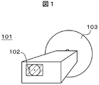
本発明の一実施例を図1によって説明する。図1は、本発明のデータ伝送システムに使用するデータ伝送装置の一実施例を説明するための図である。101はFPU装置、102はFPU装置101の筐体の外面に設けた表示部(斜線部)、103はFPU装置101の筐体の外面に設けたアンテナ部である。
放送用送受信設備において、伝送素材となる信号(映像信号及び音声信号、他)を送受信する機能を有するデータ伝送システムを構成するため、送信側と受信側のFPU装置101それぞれに、図1のように、アンテナ部103と表示部102を取り付ける。FPU装置101のアンテナ部103を除いた部分は、基本的には6面の立方体であるが、操作部、取っ手、設置台取付部、その他アクセサリ、等を設けられるような構造、アンテナ方向調整用部品、その他使い勝手、安全性、デザイン、等によって定型の立方体構造ではない。
また、アンテナの形状や大きさ等は、伝送する周波数帯によって異なる。
An embodiment of the present invention will be described with reference to FIG. FIG. 1 is a diagram for explaining an embodiment of a data transmission apparatus used in the data transmission system of the present invention.
In a broadcasting transmission / reception facility, in order to construct a data transmission system having a function of transmitting / receiving signals (video signals and audio signals, etc.) as transmission materials, each of the
The shape and size of the antenna vary depending on the frequency band to be transmitted.
図1の実施例のアンテナ部103は、FPU装置101に固定して取り付けられる。このため、作業者がFPU装置101を水平方向や垂直方向の回転するに伴って、アンテナ部103の方向も水平方向や垂直方向に回転する。アンテナ部103は、例えば、パラボラアンテナである。また、表示部102は、例えば、LCD(Liquid Crystal Display)等のFPD(Flat Panel Display)である。
また、好ましくは、表示部102は、アンテナ部103の設けられた面と、FPU装置101を挟んで対向する面に設ける。
また、好ましくは、作業者は、表示部に表示された対向する伝送装置の方向と現在の自機の伝送装置のアンテナの方向とを図形で表示し、自機の伝送装置のアンテナを向けるべき方向と現在のアンテナの方向とを一致させるように操作することによって、アンテナの方向調整を行う。
The
In addition, preferably, the
Preferably, the operator should display the direction of the opposing transmission device displayed on the display unit and the current direction of the antenna of the transmission device of the own device as a graphic, and point the antenna of the transmission device of the own device. The direction of the antenna is adjusted by performing an operation so that the direction matches the direction of the current antenna.
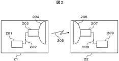
次に本発明によるデータ伝送システムを、図2を用いて説明する。図2は、FPU装置を使って伝送を行う本発明のデータ伝送システムの一実施例の構成を示すブロック図である。21は送信側のFPU装置、22は受信側(受信基地局)のFPU装置、201はFPU装置21の送信制御部、202はFPU装置21のケーブル、203はFPU装置21の送信高周波部、204はFPU装置21の送信アンテナ部、205は模式的に示した電波、206はFPU装置22の受信アンテナ部、207はFPU装置22の受信高周波部、208はFPU装置22のケーブル、209はFPU装置22の受信制御部である。
Next, a data transmission system according to the present invention will be described with reference to FIG. FIG. 2 is a block diagram showing a configuration of an embodiment of the data transmission system of the present invention that performs transmission using an FPU device. 21 is a transmission-side FPU device, 22 is a reception-side (receiving base station) FPU device, 201 is a transmission control unit of the
図2において、データ伝送システムの信号伝送経路を説明する。まず、図示しないカメラ装置からの映像信号や音声信号から成る伝送素材その他の信号が、送信制御部201に入力される。送信制御部201は、入力された信号に、信号処理及び変調処理を施し、ケーブル202を介して送信高周波部203に出力する。送信高周波部203は入力された信号をマイクロ波等の高周波信号にアップコンバートして、送信アンテナ部204を介して、電波205として放射する。
以上が、移動体に搭載される送信側のFPU装置21での信号伝送経路である。
In FIG. 2, the signal transmission path of the data transmission system will be described. First, transmission materials and other signals including video signals and audio signals from a camera device (not shown) are input to the
The above is the signal transmission path in the transmission-
次に、受信アンテナ部206は、放射された電波205を受信し、受信高周波部207に出力する。受信高周波部207は、入力された高周波信号をIF(中間周波数)信号にダウンコンバートし、ケーブル208を介して、受信制御部209に出力する。受信制御部209は入力された信号に、所定の信号処理を施し各々の信号を出力する。
以上が、中継局、基地局、等、受信側のFPU装置22での信号伝送経路である。
Next, the
The above is the signal transmission path in the reception-
なお、図1若しくは図2の実施例では、好ましくは、表示部102は、アンテナ部103の設けられた面と、FPU装置101を挟んで対向する面に設けるとしたが、FPU装置本体と、アンテナとが離れた構成であっても良い。
なお、図示していないが、送信側のFPU装置21は、例えば、TMCC(Transmission and Muliplexing Configuration and Control)信号を送信して、受信側のFPU装置22に制御情報等を伝達するが、同様に、受信側のFPU装置22から送信側のFPU装置21へにも制御情報等の伝達のために、TMCCデータを伝送する手段を有している。
In the embodiment of FIG. 1 or FIG. 2, preferably, the
Although not shown, the transmitting-
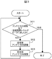
次に本発明によるアンテナ方向調整作業時のフローチャートを、図3によって説明する。図3は、本発明のデータ伝送システムにおけるアンテナ方向調整の処理動作の一実施例を説明するためのフローチャートである。図3の処理は、例えば、受信制御部209で実行する(図2参照)。
図3において、ステップ301では、作業者が表示部で確認して受信電界レベルがピークに達したか否かを確認する。ピークに達していれば、作業者は、受信側の伝送装置から、方向調整が終了したことを示す制御信号を送信側の伝送装置に出力し、アンテナ方向調整の作業を終了する。送信側の伝送装置のアンテナ方向調整の作業者は、受信された方向調整終了の制御信号によって方向調整作業を終了する。なお、所定のしきい値を設け、受信電界レベルがしきい値以上であれば、受信側の伝送装置が自動的にアンテナ方向調整が終了したと判断し、方向調整が終了したことを示す制御信号を送信側の伝送装置に出力するようにしても良い。
Next, a flowchart of the antenna direction adjustment work according to the present invention will be described with reference to FIG. FIG. 3 is a flowchart for explaining an embodiment of the antenna direction adjustment processing operation in the data transmission system of the present invention. The processing in FIG. 3 is executed by, for example, the reception control unit 209 (see FIG. 2).
In FIG. 3, in
ステップ301において、受信電界レベルがピークに達していない場合には、作業者は、受信側の伝送装置から、方向調整が必要なことを示す制御信号を送信側の伝送装置に出力し、ステップ302に進む。なお、所定のしきい値を設け、受信電界レベルがしきい値未満であれば、受信側の伝送装置が自動的にアンテナ方向調整要と判断し、調整要と表示部に表示すると共に、方向調整が必要なことを示す制御信号を送信側の伝送装置に出力するようにしても良い。
ステップ302では、送信側の伝送装置のアンテナ方向調整の作業者は、アンテナ方向調整要の制御信号を受信したことを確認して、送信側の伝送装置のアンテナ方向調整を行い、調整作業が済んだ後、送信側の伝送装置から、送信側の方向調整が済んだことを示す制御信号を受信側の伝送装置に出力し、ステップ303に進む。なお、所定のしきい値を設け、受信電界レベルがしきい値以上であれば、送信側の伝送装置が自動的にアンテナ方向調整が済みと判断し、調整作業済と表示部に表示すると共に、方向調整が済んだことを示す制御信号を受信側の伝送装置に出力するようにしても良い。
If the received electric field level does not reach the peak in
In
ステップ303では、受信側の伝送装置のアンテナ方向調整の作業者は、送信側から送信された方向調整済みの制御信号を受信後、受信側のアンテナの方向調整を行い、ステップ301に戻る。なお、所定のしきい値を設け、受信電界レベルがしきい値以上であれば、受信側の伝送装置が自動的にアンテナ方向調整が済んだと判断し、ステップ301に戻るようにしても良い。
また、図3のフローチャートにおいて、ステップ302での送信側の伝送装置のアンテナ方向調整を最初1回実行し、次のフローからは受信側の伝送装置のアンテナ方向調整(ステップ303、及びステップ301)を繰り返しても良い。また、ステップ302の実行を、受信側から指示された時だけ実行しても良い。また、ステップ302の実行を、例えば、2回おき、3回おきというように、受信側の伝送装置のアンテナ方向調整(ステップ303、及びステップ301)の実行回数より少なくしても良い。
In
Also, in the flowchart of FIG. 3, the antenna direction adjustment of the transmission apparatus on the transmission side in
図3の実施例のように、アンテナ方向調整作業は、送信側アンテナの方向調整作業を行い、受信側アンテナの方向調整作業を行う。この時、受信電界レベルがピークとなるよう、送信側の伝送装置のアンテナ方向調整作業と、受信側の伝送装置のアンテナ方向調整作業を繰り返す。受信電界レベルがピークに達したならばアンテナ方向調整作業は終了である。 As in the embodiment of FIG. 3, the antenna direction adjustment work is performed by performing the direction adjustment work of the transmission side antenna and the direction adjustment work of the reception side antenna. At this time, the antenna direction adjustment work of the transmission device on the transmission side and the antenna direction adjustment work of the transmission device on the reception side are repeated so that the reception electric field level becomes a peak. When the received electric field level reaches the peak, the antenna direction adjustment work is finished.
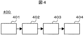
次に、本発明によるデータ伝送システムにおける伝送装置の表示部について、図4を用いて説明する。図4は、本発明の一実施例で、データ伝送システムにおけるデータ伝送装置の送信制御部若しくは受信制御部の一部である表示部の構成を説明するためのブロック図である。400は表示部、401は位置情報検出回路、402は方向計算処理回路、403は三次元表示処理回路、404は表示回路である。
図4の表示部400において、位置情報検出回路401は、GPS装置による位置検出若しくは手動による位置座標入力、又は、任意の手段により、自機の伝送装置の位置情報を認識し、かつ送信側の伝送装置から受信した送信側の伝送装置の位置情報を取得して、それらの情報を方向計算処理回路402に出力する。なお、送信側の伝送装置からの位置情報は、図2に示した受信アンテナ206、受信高周波部207、及びケーブル208を介して受信制御部209の図示しない復調回路と分離回路を通って、分離された位置情報が位置情報検出回路401に入力される。例えば、位置情報検出回路401は、GPS装置によって、所定の時間(例えば、0.33秒等)間隔で位置情報を更新し、方向計算処理回路402に出力する。
Next, the display unit of the transmission apparatus in the data transmission system according to the present invention will be described with reference to FIG. FIG. 4 is a block diagram for explaining a configuration of a display unit which is a part of a transmission control unit or a reception control unit of a data transmission apparatus in a data transmission system according to an embodiment of the present invention.
In the
方向計算処理回路402は、FPU装置等の伝送装置のアンテナを、対向する伝送装置に向けるための方向を計算し、三次元表示処理回路403に出力する。三次元表示処理回路403は、所定の形式で表示するための処理を行い、表示器404に出力する。表示器404は、アンテナ方向情報を三次元で表示する。
なお、表示器404の表示は、位置情報検出回路401の位置情報の更新時間間隔と同じでも良いし、異なっても良い。
The direction
The display on the
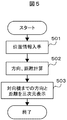
次に本発明による三次元表示処理のフローチャートを、図5によって説明する。図5は、本発明のデータ伝送システムにおける三次元表示の処理動作の一実施例を説明するためのフローチャートである。図5の処理は、例えば、受信制御部209の受信制御部の一部である表示部400で実行する(図4参照)。
図5においては、例えば、図4で説明したように、任意の手段により位置情報を入手する(ステップ501)。そして、方向、及び、距離を計算し(ステップ502)、対向の伝送装置までの方向、及び、距離を三次元表示するための処理を行う(ステップ503)。
Next, a flowchart of the three-dimensional display process according to the present invention will be described with reference to FIG. FIG. 5 is a flowchart for explaining an embodiment of the processing operation of the three-dimensional display in the data transmission system of the present invention. The process of FIG. 5 is executed by the
In FIG. 5, for example, as described with reference to FIG. 4, the position information is obtained by any means (step 501). Then, the direction and distance are calculated (step 502), and processing for displaying the direction and distance to the opposite transmission apparatus in a three-dimensional manner is performed (step 503).
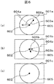
次に、本発明のデータ伝送システムにおける伝送装置の表示部について、図6を用いて説明する。図6は、本発明のデータ伝送システムにおける伝送装置の表示部に表示される画面の一実施例を説明するための図である。図6(a)、(b)、(c)は、それぞれ、本発明の表示画面例を示す図である。601a、601b、及び601cは表示画面、602はアンテナの方向調整を行う伝送装置の位置を示す点、603aと603bは現在アンテナが向いている方向を示す矢印、604aと604bは現在アンテナが向いている方向603a若しくは603bからアンテナを向けるべき水平回転の角度差を示す破線、605は半径rの円、606aと606bは水平方向にアンテナに回転させる方向を示す矢印である。矢印603a若しくは603bが円605から離れる程、即ち、矢印603aと603bの長さが短い程、受信電界レベルが大きいことを示す。また矢印606aと606bの長さは、アンテナの回転する角度が大きいほど長い。なお、矢印606aと606bは、図の説明のために図示しているもので、実際の表示画面中には表示されない。
なお、円605の大きさ(半径r)は、例えば、受信側の伝送装置が受信可能な受信電界レベルの最低値を定め、受信電界レベルがゼロの場合との差分を半径rとしている。また、好ましくは、半径rの円605は、表示部の表示画面表示画面601a、601b、601c内に表示可能な円である。例えば、表示画面が横方向に長い長方形であれば、表示画面の縦方向の長さの半分と一致するか、あるいは少し半径が小さい円である。さらに好ましくは、表示画面が円形であれば、表示画面の円の半径と一致するか、あるいは少し小さい円である。
また好ましくは、アンテナの方向調整を行う伝送装置の位置を示す点602は、表示画面の中央である。
Next, the display unit of the transmission apparatus in the data transmission system of the present invention will be described with reference to FIG. FIG. 6 is a diagram for explaining an example of a screen displayed on the display unit of the transmission apparatus in the data transmission system of the present invention. 6A, 6B, and 6C are diagrams showing examples of display screens according to the present invention. 601a, 601b, and 601c are display screens, 602 is a point indicating the position of the transmission apparatus that performs antenna direction adjustment, 603a and 603b are arrows indicating the direction in which the antenna is currently facing, and 604a and 604b are facing the current antenna. A broken line indicating the angle difference of the horizontal rotation in which the antenna should be directed from the
Note that the size (radius r) of the
Also preferably, a
先ず、作業者が伝送装置のアンテナ調整を開始した場合には、アンテナ方向が合っていないのが普通である。従って、図6(a)に示すように、作業者が見た表示部の表示画面601aでは、伝送装置の位置を示す点602から出ている現在アンテナが向いている方向を示す矢印603a、アンテナを向けるべき方向を示す破線604a、及び、基準となる所定の受信電界レベルを示す円605とが表示される。そして、矢印603aと破線604aとは、点602からそれぞれ異なる角度で伸びている。
First, when an operator starts antenna adjustment of the transmission apparatus, the antenna direction is usually not correct. Therefore, as shown in FIG. 6A, on the
作業者が行うアンテナ方向調整作業は、表示部の表示画面が示すベクトルの向きに応じて調整する。
図6(a)の表示画面601aのように表示されている場合には、矢印603aに示すように、アンテナは右上方向を向いており、破線604aが示すアンテナを向けるべき方向は、左上方向に向いている。即ち、現在アンテナが向いている方向を示す矢印603aより左側に、アンテナを向けるべき方向を示す破線604aが表示されていれば、作業者は左水平方向にアンテナを回転させる。
このような場合には、アンテナ方向調整作業が必要であり、このベクトルが表示されないように調整する。また、作業者が回転させる角度は、例えば、表示画面601aの表示されている角度差分である。即ち、作業者は、この矢印603aが向いている方向から破線604aの伸びている方向(左側)に、アンテナの方向を水平方向(矢印606aの方向)に回転させる。
The antenna direction adjustment work performed by the operator is adjusted according to the direction of the vector indicated by the display screen of the display unit.
When the
In such a case, antenna direction adjustment work is necessary, and adjustment is performed so that this vector is not displayed. Moreover, the angle which an operator rotates is an angle difference currently displayed on the
また、図6(b)に示す表示画面601bが表示部に表示される場合には、矢印603bに示すように、アンテナは右下方向を向いている。また、アンテナを向けるべき方向を示す破線604bは右上方向に向いている。
このような場合には、アンテナ方向調整作業が必要であり、このベクトルが表示されないように調整する。即ち、作業者は、この矢印603bが向いている方向から破線604bの伸びている方向に、アンテナの方向を水平方向(矢印606bの方向)に回転させる。即ち、作業者は、この矢印603bが向いている方向から破線604bの伸びている方向(右側)に、アンテナの方向を水平方向(矢印606aの方向)に回転させる。
In addition, when the
In such a case, antenna direction adjustment work is necessary, and adjustment is performed so that this vector is not displayed. That is, the worker rotates the direction of the antenna in the horizontal direction (the direction of the
そして、アンテナ方向が、入手された位置情報に基づき、あらかじめ計算された方向に向いた場合は、図6(c)の表示画面601cに示すように、点602と円605だけが示され、矢印603aや603b、破線604aや604bは表示されない。
即ち、図6(c)に示すような、アンテナ方向を示すベクトル表示例(表示画面601c)となった場合に、アンテナ方向調整の作業が終了となる。
Then, when the antenna direction is in the direction calculated in advance based on the obtained position information, only the
That is, when the vector display example (
なお、方向を表示するための演算には、例えば、地学書などに記載の計算式を用いる。即ち、任意の地点における対向するデータ伝送装置までの方向(角度情報を含む)及び距離は、入手した自機データ伝送装置の位置情報を含めた位置情報情報により計算できる。 For the calculation for displaying the direction, for example, a calculation formula described in a geography book is used. That is, the direction (including the angle information) and the distance to the opposing data transmission device at an arbitrary point can be calculated from the positional information information including the obtained positional information of the own data transmission device.
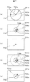
本発明のデータ伝送システムにおける伝送装置の表示部の別の表示例について、さらに図7を用いて説明する。図7は、本発明のデータ伝送システムにおける伝送装置の表示部に表示される画面の一実施例を説明するための図である。図7(a)、(b)、(c)、(d)、及び(e)は、それぞれ、本発明の表示画面例を示す図である。701a、701b、701c、701d、及び701eは表示画面、702はアンテナの方向調整を行う伝送装置の位置を示す点、703aと703bは現在アンテナが向いている方向を示す矢印、704a及び704bは現在アンテナが向いている方向703a若しくは703bからアンテナを向けるべき水平回転の角度差を示す破線、705a、705b、及び705dは受信側の伝送装置が受信可能な受信電界レベルの最低値を定め、受信電界レベルがゼロの場合との差分を半径とした円、705eは現在のアンテナ方向とアンテナを向けるべき水平方向とのずれ量(ずれ角)の大きさを半径等の大きさで示した円、706aと706bはアンテナを水平方向に回転させる方向を示す矢印である。矢印703a又は703bと円705は、受信電界レベルの大きさを示す。即ち、矢印703aと703bの長さが短い程、受信電界レベルが大きいことを示す。なお、矢印706aと706bは、図の説明のために図示しているもので、実際の表示画面中には表示されない。
Another display example of the display unit of the transmission apparatus in the data transmission system of the present invention will be further described with reference to FIG. FIG. 7 is a diagram for explaining an example of a screen displayed on the display unit of the transmission apparatus in the data transmission system of the present invention. 7A, 7B, 7C, 7D, and 7E are diagrams showing examples of display screens according to the present invention. 701a, 701b, 701c, 701d, and 701e are display screens, 702 is a point indicating the position of a transmission apparatus that performs antenna direction adjustment, 703a and 703b are arrows indicating the direction in which the antenna is currently facing, and 704a and 704b are current A broken line indicating the angle difference of horizontal rotation in which the antenna should be directed from the
なお、例えば、図7(d)に示すように、半径rの破線の円705a’と、円705dの半径との差が受信電界レベルの不足分、若しくは絶対値を示しても良い。即ち、図6でも述べたように、円605の大きさは、例えば、受信側の伝送装置が受信可能な受信電界レベルの最低値を定め、定められた電界レベルを半径rとしている。また、好ましくは、半径rの円605は、表示部の表示画面表示画面601a、601b、601c内に表示可能な円である。
For example, as shown in FIG. 7D, the difference between the
なお、例えば、図7(e)に示すように、円705eの大きさで、現在のアンテナの向いている方向と、アンテナを向けるべき水平方向とのずれ量(ずれ角)の大きさを半径等の大きさで示しでも良い。矢印703aは、現在のアンテナの向いている方向を示すが、その長さは受信電界レベルを示し、アンテナを向けるべき水平方向とのずれ量(ずれ角)を円の大きさで示すものである。
For example, as shown in FIG. 7 (e), the size of a
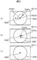
さらに、本発明のデータ伝送システムにおける伝送装置の表示部の別の表示例について、図8を用いて説明する。図8は、本発明のデータ伝送システムにおける伝送装置の表示部に表示される画面の一実施例を説明するための図である。図8(a)、(b)、(c)は、それぞれ、本発明の表示画面例を示す図である。図8の実施例は、図8(a)と図6(a)、及び図8(c)と図6(c)の表示画面601a、601cは全く同じである。異なる点は、図6(b)における現在アンテナが向いている方向を示す矢印603bが、図8(b)においては白色(若しくは白抜き)の矢印803bとなっていることである。
Furthermore, another display example of the display unit of the transmission apparatus in the data transmission system of the present invention will be described with reference to FIG. FIG. 8 is a diagram for explaining an example of a screen displayed on the display unit of the transmission apparatus in the data transmission system of the present invention. 8A, 8B, and 8C are diagrams showing examples of display screens according to the present invention. In the embodiment of FIG. 8, the
図8においては、図6や図7の実施例において、アンテナの方向調整を水平方向に回転させるように表示していたところ、垂直方向即ち仰角を回転させるように表示を行ったものである。即ち、図8(a)の矢印603aは、水平方向に回転させる表示の他、上方向に回転させるために、黒色表示としている。これに対して図8(b)の矢印803bは、水平方向に回転させる表示の他、下方向に回転させるために、白色表示としている。なお、矢印603aと矢印803bとを作業者が区別できれば良いのであって、表示色を変えるとか、一方を常時表示し、他方を点滅表示する様にしても良い。若しくは、形状を変更しても良い。
なお、図8においても、矢印606aと606bは、説明のために図示しているもので、実際の表示画面中には表示されない。
In FIG. 8, in the embodiment of FIG. 6 and FIG. 7, the antenna direction adjustment is displayed so as to rotate in the horizontal direction, but the display is performed so as to rotate the vertical direction, that is, the elevation angle. That is, the
In FIG. 8, the
図8の実施例においては、垂直方向の回転の大きさが表示されていない。しかし、例えば、受信電界レベルを図7の実施例のように、円の半径で表示し、矢印を現在のアンテナの垂直方向の角度と、アンテナを向けるべき垂直方向の角度との差分(仰角の差分)を、矢印の長さで表示することによって、垂直方向の回転の大きさを表示することができ、作業者は、水平回転だけでなく垂直方向のアンテナ方向調整が容易に可能となる。
好ましくは、アンテナの垂直方向の回転すべき角度を、図8の矢印603aや803bで、矢印の一部の表示を変えるようにしても良い、例えば、矢印の長さ自体を90度とし、45度回転が必要な場合には、矢印の半分まで別の色で表示する、30度回転が必要であれ矢印の3分の1まで別の色で表示する、等である。また好ましくは、矢印603aや803bの替わりに、アンテナを向けるべき水平回転の角度差を示す破線604a、604bを同様にしても良い。
In the embodiment of FIG. 8, the magnitude of the vertical rotation is not displayed. However, for example, the received electric field level is represented by the radius of a circle as in the embodiment of FIG. 7, and the arrow is the difference between the vertical angle of the current antenna and the vertical angle to which the antenna should be directed (the elevation angle). By displaying the difference) by the length of the arrow, the magnitude of the vertical rotation can be displayed, and the operator can easily adjust the antenna direction in the vertical direction as well as the horizontal rotation.
Preferably, the angle of the antenna to be rotated in the vertical direction may be changed with the
また好ましくは、図6〜図8の実施例における伝送装置の位置を示す点602を、中心から上に移動して表示した場合には、その中心点との差分程度、作業者が仰角を下に向けるように、また、中心から下に移動して表示した場合には、その中心点との差分程度、作業者が仰角を上に向けるように、アンテナの方向を垂直回転操作するようにしても良い。この場合、アンテナの現在向いている方向を示す矢印の長さは、受信電界レベルを示すようにしても良い。
Preferably, when the
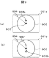
本発明のデータ伝送システムにおける伝送装置の表示部の別の表示例について、さらに、図9を用いて説明する。図9(a)、図9(b)は、本発明のデータ伝送システムにおける伝送装置の表示部に表示される画面の一実施例を説明するための図である。901a及び901bは表示画面、903a、903bは現在アンテナが向いている方向を示す矢印、904はアンテナを向けるべき水平回転の角度差を示す破線、905は図7と同様に、現在の受信電界レベルを示す円、907は現在アンテナをアンテナを向けるべき波線904の方向に向けるための基準線である。
Another display example of the display unit of the transmission apparatus in the data transmission system of the present invention will be further described with reference to FIG. FIG. 9A and FIG. 9B are diagrams for explaining an example of a screen displayed on the display unit of the transmission apparatus in the data transmission system of the present invention. 901a and 901b are display screens, 903a and 903b are arrows indicating the direction in which the antenna is currently directed, 904 is a broken line indicating the angle difference of horizontal rotation to which the antenna should be directed, and 905 is the current received electric field level as in FIG. A
図9の実施例は、図6〜図8の実施例において、現在アンテナが向いている方向を、表示画面901の垂直方向に固定したものである。即ち、図9(a)において、現在アンテナが向いている方向を示す矢印903の示す方向を、表示画面901内で、伝送装置の位置を示す点602を中心とし、点602を通る垂直線上に表示するようにする。その時、アンテナを向けるべき水平回転の角度差を示す破線904が、周知の演算式によって矢印903に対して相対的に定まり、表示される。図9(a)は、アンテナの水平回転方向を示す他、点602より上に矢印を示し、対向する伝送装置の上方向に矢印の長さ分向いている場合であることを示す。従って、作業者は、アンテナ方向を破線904方向に水平回転すると共に、下方向に垂直回転する。
The embodiment of FIG. 9 is obtained by fixing the direction in which the antenna is currently facing in the vertical direction of the display screen 901 in the embodiments of FIGS. That is, in FIG. 9A, the direction indicated by the arrow 903 indicating the direction in which the antenna is currently directed is on the vertical line passing through the
更に、図9(b)においては、点602より下に矢印を示し、対向する伝送装置の上方向に矢印の長さ分向いていることを示す。従って、作業者は、アンテナ方向を破線904方向に水平回転すると共に、上方向に垂直回転する。しかし、点602の下に現在アンテナが向いている方向を示す矢印903bがあると、作業者が、矢印903bから破線904の方向に右回転させる可能性がある。このような錯覚を防ぐため、現在アンテナをアンテナを向けるべき波線904の方向に向けるための基準線907を表示し、水平回転の基準線とした。
なお、基準線の形状、色等の表示は、実施例に限定するものではなく、任意で良い。
Further, in FIG. 9B, an arrow is shown below the
The display of the shape, color, etc. of the reference line is not limited to the embodiment, and may be arbitrary.
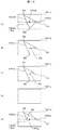
さらに、本発明のデータ伝送システムにおける伝送装置の表示部の別の表示例について、図10を用いて説明する。図10は、本発明のデータ伝送システムにおける伝送装置の表示部に表示される画面の一実施例を説明するための図である。100axは表示画面1001aの水平方向の中心軸(水平軸)、100ayは表示画面1001aの垂直方向の中心軸(垂直軸)、1001a、1001b、1001c、1001d、及び1001eは表示画面、1002a(Oa)、Ob、及びOcはアンテナの方向調整を行う伝送装置の位置を示す点、1003a、1003b、1003c、及び1003eは現在アンテナが向いている方向を示す矢印、Aa、Ba、及びCaは矢印1003aの三角形の頂点、Ab、Bb、Cb、及びObは矢印1003bの頂点、Ac、Bc、Cc、及びOcは矢印1003cの頂点、Beは矢印1003eの1つの頂点である。
Furthermore, another display example of the display unit of the transmission apparatus in the data transmission system of the present invention will be described with reference to FIG. FIG. 10 is a diagram for explaining an example of a screen displayed on the display unit of the transmission apparatus in the data transmission system of the present invention. 100ax is a horizontal center axis (horizontal axis) of the
図10(a)の表示画面1001aは、三角形1003aの形状や大きさでアンテナの方向調整情報が分かるようにしたものである。即ち、点1002a(Oa)は、アンテナの方向調整を行う伝送装置の位置を示し、この点Oaから頂点Aaに伸びる直線とアンテナ方向は垂直軸100yの角度差分が現在のアンテナの水平方向に回転する方向を示す。即ち、垂直軸100ayより左側に頂点Aaが表示されていれば、作業者は左水平方向にアンテナを回転させる。
このとき、頂点BaとCaとを結ぶ直線の長さは、水平方向に回転させる角度に応じた長さであり、作業者は、この直線が長い程、より大きい角度でアンテナの方向を水平回転する。
The
At this time, the length of the straight line connecting the vertices Ba and Ca is a length corresponding to the angle to be rotated in the horizontal direction, and the operator horizontally rotates the antenna direction at a larger angle as the straight line becomes longer. To do.
また、好ましくは、頂点Aa、Ba、及びCaの区別を作業者がつけ易くするため、それぞれを別々の色で表示する、等、頂点に装飾を施す。
また、好ましくは、頂点Baを垂直軸100ay上に表示し、点Oaから頂点Baに伸びる直線が、アンテナを向けるべき垂直方向を示し、その直線間の長さが垂直回転する角度量に応じた長さで表示される。従って、作業者は、この直線が長い程、より大きい角度でアンテナの方向を垂直回転する。
より好ましくは、図10(e)の表示画面1001eに示すように、現在のアンテナの垂直方向(仰角)が、アンテナを向けるべき方向より下向きであった場合に、三角形1003aの下側を折り返す形状の矢印1003eとなり、垂直回転の方向を作業者に分かり易くする。
Preferably, in order to make it easy for the operator to distinguish the vertices Aa, Ba, and Ca, decorations are applied to the vertices, such as displaying them in different colors.
Preferably, the vertex Ba is displayed on the vertical axis 100ay, and a straight line extending from the point Oa to the vertex Ba indicates a vertical direction in which the antenna should be directed, and a length between the straight lines corresponds to an angular amount of vertical rotation. Displayed in length. Therefore, the operator rotates the direction of the antenna vertically by a larger angle as the straight line becomes longer.
More preferably, as shown in a
次に、図10(b)の表示画面1001bは、矢じり形の矢印1003bの形状や大きさでアンテナの方向調整情報が分かるようにしたものである。即ち、点Obが、アンテナの方向調整を行う伝送装置の位置を示し、アンテナの水平方向に回転させる方向は、この点Obから頂点Abに伸びる直線と、表示画面1001bの垂直な線との角度差で判断することができる。即ち、表示画面の左に傾いて矢印の頂点Abが表示されていれば、作業者は左水平方向にアンテナを回転させる。また、表示画面の右に傾いて矢印の頂点Abが表示されていれば、作業者は右水平方向にアンテナを回転させる。
更に、点Obから頂点Bbに伸びる直線が、アンテナを向けるべき垂直方向を示し、その直線間の長さが垂直回転する角度量に応じた長さで表示される。従って、作業者は、この直線が長い程、より大きい角度でアンテナの方向を垂直回転する。
Next, the
Further, a straight line extending from the point Ob to the apex Bb indicates a vertical direction in which the antenna should be directed, and the length between the straight lines is displayed with a length corresponding to the amount of angular rotation. Therefore, the operator rotates the direction of the antenna vertically by a larger angle as the straight line becomes longer.
更に、点Obから頂点Bbに伸びる直線が、アンテナを向けるべき垂直方向を示し、その直線間の長さが垂直回転する角度量に応じた長さで表示される。従って、作業者は、この直線が長い程、より大きい角度でアンテナの方向を垂直回転する。
また、好ましくは、図10(a)と図10(e)と同様に、垂直方向の回転の向きに応じて、矢印が折り返し表示される。
また、好ましくは、頂点Ab、Bb、及びCbの区別を作業者がつけ易くするため、それぞれを別々の色で表示する、等、頂点に装飾を施す。
Further, a straight line extending from the point Ob to the apex Bb indicates a vertical direction in which the antenna should be directed, and the length between the straight lines is displayed with a length corresponding to the amount of angular rotation. Therefore, the operator rotates the direction of the antenna vertically by a larger angle as the straight line becomes longer.
Preferably, as in FIGS. 10A and 10E, an arrow is displayed in a folded manner according to the direction of rotation in the vertical direction.
Preferably, the apexes Ab, Bb, and Cb are decorated with respect to the apexes so that the operator can easily distinguish the apexes Ab, Bb, and Cb.
次に、図10(c)の表示画面1001cは、矢じり形の矢印1003cの形状や大きさでアンテナの方向調整情報が分かるようにしたものである。即ち、点Ocが、アンテナの方向調整を行う伝送装置の位置を示し、アンテナの水平方向に回転させる方向は、この点Ocから頂点Acに伸びる直線と、表示画面1001cの垂直な線との角度差で判断することができる。即ち、表示画面の左に傾いて矢印の頂点Acが表示されていれば、作業者は左水平方向にアンテナを回転させる。また、表示画面の右に傾いて矢印の頂点Acが表示されていれば、作業者は右水平方向にアンテナを回転させる。
このとき、頂点OcとCcとを結ぶ直線の長さは、受信電界レベルに応じた長さであり、作業者は、この直線が長い程、受信電界レベルが大きいと判断する。従って、作業者は、この長さが小さい、即ち、受信電界レベルが小さい場合にはより大きい角度でアンテナの方向を水平回転する。
Next, the
At this time, the length of the straight line connecting the vertices Oc and Cc is a length according to the received electric field level, and the operator determines that the longer the straight line is, the higher the received electric field level is. Therefore, the operator rotates the direction of the antenna horizontally at a larger angle when this length is small, that is, when the received electric field level is small.
更に、点Ocから頂点Bcに伸びる直線が、受信される電波のBER(Bit Error Rate)を示し、その直線が長いほど、BERが大きい。従って、作業者は、この直線が長い程、より大きい角度でアンテナの方向を垂直回転する。
また、好ましくは、図10(a)と図10(e)と同様に、垂直方向の回転の向きに応じて、矢印が折り返し表示される。
また、好ましくは、頂点Ac、Bc、及びCcの区別を作業者がつけ易くするため、それぞれを別々の色で表示する、等、頂点に装飾を施す。
Furthermore, a straight line extending from the point Oc to the vertex Bc indicates the BER (Bit Error Rate) of the received radio wave, and the longer the straight line, the larger the BER. Therefore, the operator rotates the direction of the antenna vertically by a larger angle as the straight line becomes longer.
Preferably, as in FIGS. 10A and 10E, an arrow is displayed in a folded manner according to the direction of rotation in the vertical direction.
Preferably, in order to make it easy for the operator to distinguish the vertices Ac, Bc, and Cc, the vertices are decorated such as displaying them in different colors.
図10(a)〜図10(c)の表示において、アンテナの方向調整が終了した場合には、図10(d)に示す表示画像1001dに示すように、何も表示されなくなるか、又は、方向調整が成功したことを示す表示がなされる。あるいは、所定の値以上の受信電界レベルに達すれば、矢印等の表示がそのままで、表示画面の表示色が別の色に切り替わっても良い。
In the display of FIGS. 10A to 10C, when the antenna direction adjustment is completed, nothing is displayed as shown in a
なお、表示画面の更新は、図4の実施例において、位置情報検出回路401の位置情報の更新時間間隔と同じでも良いし、異なっても良いとしたが、アンテナの方向を水平若しくは垂直方向に回転する場合に、回転中に表示を更新すると作業者が見難い場合もあるので、例えば、回転動作が所定時間(例えば、1秒)以上停止している場合には、図4の実施例のように更新し、回転動作中は表示を更新しないようにする。また、例えば、アンテナ方向調整中には、操作ボタンを押すことによって、表示画面を更新するようにしても良い。
The update of the display screen may be the same as or different from the update time interval of the position information of the position
また、上記図6〜図10の実施例において、データ伝送装置のアンテナの方向調整が終了した場合には、現在アンテナが向いている方向を示す矢印やアンテナを向けるべき水平回転の角度差を示す破線等が表示されなくなるようにしていた。しかし、図10でも述べたように、表示色を変更するか、方向調整終了を示す情報を表示しても良いし、例えば、受信電界レベルの基準を示す円を表示画面一杯に広げたり、円の太さを太くする等、変更するようにしても良い。 Further, in the embodiments of FIGS. 6 to 10, when the direction adjustment of the antenna of the data transmission apparatus is completed, an arrow indicating the direction in which the antenna is currently directed and the angle difference of the horizontal rotation to which the antenna should be directed are shown. The broken lines were not displayed. However, as described in FIG. 10, the display color may be changed or information indicating the end of the direction adjustment may be displayed. For example, a circle indicating the reference of the received electric field level may be expanded to fill the display screen. The thickness may be changed, for example, by increasing the thickness.
また、図10(c)の実施例では、受信電界レベルとBERを表示するようにした。しかし、BERの外、例えば、遅延プロファイルや、主波と反射波との差分を表示するようにしても良い。かつ、アンテナ調整方向の水平回転方向及び垂直回転方向の表示と、受信電界レベル、BER、その他、方向調整に関わる情報を必要に応じて、多次元表示するようにして良いことは勿論のこと、テキスト表示、その他の図形表示、音声出力、等を組み合わせても良い。
さらに、表示画面1001b〜1001dにおいて、水平軸100x及び垂直軸100yを表示していないが、表示しても良いことはもちろんであり、表示画面1001a及び1001dにおいて、水平軸100x及び垂直軸100yを表示しなくても良いことも勿論である。
In the embodiment of FIG. 10C, the received electric field level and the BER are displayed. However, in addition to the BER, for example, a delay profile or a difference between the main wave and the reflected wave may be displayed. And, of course, it is possible to display the horizontal adjustment direction and the vertical rotation direction of the antenna adjustment direction, the received electric field level, the BER, and other information related to the direction adjustment, if necessary, in a multidimensional manner. Text display, other graphic display, audio output, and the like may be combined.
Further, although the horizontal axes 100x and the vertical axes 100y are not displayed on the
表示方法としては、入手した位置情報から、一例として、表示器に矢印表示する。長さは対向機までの距離を表し、方向は現状のFPU装置の向きを表す。
なお、表示器は液晶ディスプレイ(Liquid Crystal Display)等、多岐にわたる表示器を使用できる。表示方法としては、対向する機器の方向を三次元で示し、向けるべき方向と、実際に機器が向いている方向を一致させる。
As a display method, an arrow is displayed on the display as an example from the acquired position information. The length represents the distance to the opposite device, and the direction represents the direction of the current FPU device.
A wide variety of displays such as a liquid crystal display can be used as the display. As a display method, the direction of the facing device is shown in three dimensions, and the direction to be directed is matched with the direction in which the device is actually facing.
上述した実施例の結果、対向となるデータ伝送装置のアンテナ方向、即ち、アンテナを向けるべき方向を表示し、実際にデータ伝送装置のアンテナが向いている方向を表示し、その方向が一致した場合、本発明により、可視化により作業が容易化され、アンテナ方向が確認できる。このように三次元等の多次元で可視化することによりアンテナ方向調整の作業効率の向上、作業時間の短縮、及び、精度向上が可能となる。 As a result of the above-described embodiment, the antenna direction of the opposite data transmission device, that is, the direction in which the antenna should be directed is displayed, the direction in which the antenna of the data transmission device is actually facing is displayed, and the directions match According to the present invention, the work is facilitated by visualization, and the antenna direction can be confirmed. By visualizing in three dimensions such as three dimensions in this way, it is possible to improve the work efficiency of the antenna direction adjustment, shorten the work time, and improve the accuracy.
以上のように、本発明のデータ伝送システムは、任意の手段により得た位置情報を可視化し、送信側と受信側に設けられたFPU装置等のデータ伝送装置のアンテナの方向調整を容易に行うために、FPU装置等のデータ伝送装置のアンテナが設けられた面と反対側の面に表示部の表示画面を設け、作業者がアンテナの方向調整を行いながら、表示画面の表示を見ることで、方向調整すべき方向が容易に分かり、かつ、受信電界レベルがピークになったことが容易に判別できる表示を実現するものである。
即ち、本発明のFPU装置等のデータ伝送装置を使用したデータ伝送システムでは、任意の手段により得た位置情報を、可視化表示する機能を搭載し、表示部に位置情報の要素1つに対して一次元ずつ表示(多次元表示)するものである。
As described above, the data transmission system of the present invention visualizes the position information obtained by an arbitrary means, and easily adjusts the direction of the antenna of the data transmission apparatus such as the FPU apparatus provided on the transmission side and the reception side. Therefore, the display screen of the display unit is provided on the surface opposite to the surface where the antenna of the data transmission device such as the FPU device is provided, and the operator can view the display screen while adjusting the direction of the antenna. Thus, it is possible to realize a display in which the direction to be adjusted can be easily understood and the reception electric field level can be easily discriminated.
That is, in the data transmission system using the data transmission apparatus such as the FPU apparatus of the present invention, a function for visualizing and displaying the position information obtained by an arbitrary means is installed, and one element of the position information is displayed on the display unit. Display one dimension at a time (multi-dimensional display).
上記実施例では、アンテナの方向調整を、主に作業者が手動で行っていた。しかし、方向変更機構部と方向調整操作用のパネル部とを伝送装置に設け、若しくは外付けし、作業者のパネル操作に応じてアンテナ方向を調整しても良い。またさらに、図4で説明した方向計算処理回路402、等の表示部400、又は、図2で説明した送信制御部201若しくは受信制御部209が自動的に処理するようにしても良い。
In the above-described embodiment, the operator has mainly manually adjusted the direction of the antenna. However, the direction changing mechanism and the panel for adjusting the direction may be provided in the transmission apparatus or externally attached, and the antenna direction may be adjusted according to the panel operation of the operator. Furthermore, the
また、上記実施例では、アンテナ方向調整後、送信側と受信側の伝送装置で送受信を実施するが、例えば、送信側の伝送装置がヘリコプター等の常に移動している若しくは時々移動する移動体に搭載されている場合には、送信側では、固定された受信側の伝送装置の位置を記憶し、自移動体の位置(高度を含む)を、任意の手段で取得して、自動的にアンテナ方向を調整するようにしても良い。 Further, in the above embodiment, after the antenna direction is adjusted, transmission / reception is performed by the transmission device on the transmission side and the reception side. For example, the transmission device on the transmission side is constantly moving or sometimes moving, such as a helicopter. If it is installed, the transmitting side memorizes the position of the fixed transmission device on the receiving side, acquires the position of the mobile unit (including altitude) by any means, and automatically uses the antenna. The direction may be adjusted.
また本発明の別の実施例のデータ伝送システムでは、送信側の伝送装置に、ジャイロ等の三次元移動履歴検出記録手段を設け、現地に移動する前に、事前に放送局等の受信側の伝送装置のアンテナと、基地局等に近接して対向させ、先ず、ジャイロ等の三次元移動履歴検出記録手段を含めてイニシャライズしておき、送信側の伝送装置の移動方向を監視して自動的に送信側の伝送装置のアンテナ方向を調整する。そして、この三次元移動履歴検出記録手段が取得した移動情報が、送信側の伝送装置の、例えば、TMCC信号に付与されて送信されてくるため、受信側のデータ伝送装置では、その移動情報に基づいてアンテナの方向調整を実施することができる。
また、好ましくは、受信側の伝送装置のアンテナは、通常中継作業実施時と同じ場所に設けられたまま、事前のアンテナ調整が実施される。
上記実施例では、送信側の受信装置と受信側の伝送装置で連絡を取りあって、それぞれのアンテナの方向調整を行う必要が無いため、さらに作業効率が向上する。
In the data transmission system of another embodiment of the present invention, the transmission apparatus on the transmission side is provided with a three-dimensional movement history detection recording means such as a gyro, and before moving to the site, the reception side such as a broadcasting station in advance. Make the antenna of the transmission device face the base station in close proximity, and first initialize it including the three-dimensional movement history detection and recording means such as a gyro, and automatically monitor the direction of movement of the transmission device on the transmission side. Adjust the antenna direction of the transmission device on the transmission side. Then, since the movement information acquired by the three-dimensional movement history detection recording means is added to, for example, a TMCC signal of the transmission apparatus on the transmission side and transmitted, the data transmission apparatus on the reception side includes the movement information. Based on this, the antenna direction can be adjusted.
Preferably, prior antenna adjustment is performed while the antenna of the transmission apparatus on the reception side is provided at the same place as when the normal relay operation is performed.
In the above embodiment, since it is not necessary to communicate between the receiving device on the transmitting side and the transmitting device on the receiving side and adjust the direction of each antenna, the working efficiency is further improved.
21:送信側のFPU装置、 22:受信側(受信基地局)のFPU装置、 100ax:水平軸、 100ay:垂直軸、 101:FPU装置、 102:表示部、 103:アンテナ部、 201:送信制御部、 202:ケーブル、 203:送信高周波部、 204:送信アンテナ部、 205:電波、 206:受信アンテナ部、 207:受信高周波部、 208:ケーブル、 209:受信制御部、 400:表示部、 401:位置情報検出回路、 402:方向計算処理回路、 403:三次元表示処理回路、 404:表示回路、 601a、601b、601c:表示画面、 602:伝送装置の位置を示す点、 603a、603b:現在アンテナが向いている方向を示す矢印、 604a、604b:アンテナを向けるべき水平回転の角度差を示す破線、 605:円、 606a、606b:アンテナを水平方向に回転させる方向を示す矢印、 701a、701b、701c、701d:表示画面、 702:伝送装置の位置を示す点、 703a、703b:現在アンテナが向いている方向を示す矢印、 704a、704b:アンテナを向けるべき水平回転の角度差を示す破線、 705a、705b、705d:円、 、705e:ずれ量(ずれ角)の大きさを示す円、 706a、706b:アンテナを水平方向に回転させる方向を示す矢印、 801b:表示画面、 803b:現在アンテナが向いている方向を示す矢印、 901a、901b:表示画面、 903a、903b:現在アンテナが向いている方向を示す矢印、 904:アンテナを向けるべき水平回転の角度差を示す破線、 905:現在の受信電界レベルを示す円、 907:基準線、 1001a、1001b、1001c、1001d、1001e:表示画面、 1002a(Oa)、Ob、Oc:アンテナの方向調整を行う伝送装置の位置を示す点、 1003a、1003b、1003c、1003e:現在アンテナが向いている方向を示す矢印、 Aa、Ba、Ca:矢印1003aの三角形の頂点、 Ab、Bb、Cb、Ob:矢印1003bの頂点、 Ac、Bc、Cc、Oc:矢印1003cの頂点、 Be:矢印1003eの頂点。 21: FPU device on transmitting side, 22: FPU device on receiving side (receiving base station), 100ax: horizontal axis, 100ay: vertical axis, 101: FPU device, 102: display unit, 103: antenna unit, 201: transmission control 202: Cable, 203: Transmission high-frequency unit, 204: Transmission antenna unit, 205: Radio wave, 206: Reception antenna unit, 207: Reception high-frequency unit, 208: Cable, 209: Reception control unit, 400: Display unit, 401 : Position information detection circuit, 402: Direction calculation processing circuit, 403: Three-dimensional display processing circuit, 404: Display circuit, 601a, 601b, 601c: Display screen, 602: Point indicating the position of the transmission device, 603a, 603b: Current Arrows indicating the direction in which the antenna is facing, 604a, 604b: horizontal to which the antenna should be directed 605: Circle, 606a, 606b: Arrow indicating the direction of rotating the antenna in the horizontal direction, 701a, 701b, 701c, 701d: Display screen, 702: Point indicating the position of the transmission device, 703a , 703b: arrows indicating the direction in which the antenna is currently directed, 704a, 704b: broken lines indicating the angle difference of horizontal rotation to which the antenna should be directed, 705a, 705b, 705d: circles, 705e: large amount of deviation (deviation angle) 706a, 706b: arrows indicating the direction in which the antenna is rotated in the horizontal direction, 801b: display screen, 803b: arrows indicating the direction in which the antenna is currently facing, 901a, 901b: display screen, 903a, 903b: Arrow indicating the direction the antenna is currently facing, 904: Water to which the antenna should be directed 905: Circle indicating current reception electric field level, 907: Reference line, 1001a, 1001b, 1001c, 1001d, 1001e: Display screen, 1002a (Oa), Ob, Oct: Direction adjustment of antenna 1003a, 1003b, 1003c, 1003e: arrows indicating the direction in which the antenna is currently facing, Aa, Ba, Ca: vertices of triangles of arrows 1003a, Ab, Bb, Cb, Ob: Vertex of arrow 1003b, Ac, Bc, Cc, Oc: Vertex of arrow 1003c, Be: Vertex of arrow 1003e.
Claims (1)
前記送信側データ伝送装置の前記送信制御部、若しくは、前記受信側データ伝送装置の受信制御部は、
任意の手段により位置情報を検出する位置情報検出回路と、該検出された位置情報に基づいて、現在のアンテナの方向、アンテナの方向調整すべき水平方向、及びアンテナの方向調整すべき垂直方向を少なくとも算出する方向計算処理回路と、該算出された現在のアンテナの方向、アンテナの方向調整すべき水平方向、及びアンテナの方向調整すべき垂直方向を表示するための表示回路とを備えた表示部とから成ることを特徴とするデータ伝送システム。 Mounted on a mobile unit, it consists of a transmission control unit, a transmission high-frequency unit, and a transmission antenna, and includes a transmission-side data transmission device that wirelessly transmits a video signal, a reception antenna, a reception high-frequency unit, and a reception control unit. In a data transmission system composed of a receiving side data transmission device,
The transmission control unit of the transmission side data transmission device, or the reception control unit of the reception side data transmission device,
A position information detection circuit for detecting position information by an arbitrary means, and a current antenna direction, a horizontal direction to adjust the antenna direction, and a vertical direction to adjust the antenna direction based on the detected position information. A display unit comprising at least a direction calculation processing circuit to be calculated, and a display circuit for displaying the calculated current antenna direction, a horizontal direction to adjust the antenna direction, and a vertical direction to adjust the antenna direction A data transmission system comprising:
Priority Applications (1)
| Application Number | Priority Date | Filing Date | Title |
|---|---|---|---|
| JP2008312427A JP2010136282A (en) | 2008-12-08 | 2008-12-08 | Data transmission system |
Applications Claiming Priority (1)
| Application Number | Priority Date | Filing Date | Title |
|---|---|---|---|
| JP2008312427A JP2010136282A (en) | 2008-12-08 | 2008-12-08 | Data transmission system |
Publications (2)
| Publication Number | Publication Date |
|---|---|
| JP2010136282A true JP2010136282A (en) | 2010-06-17 |
| JP2010136282A5 JP2010136282A5 (en) | 2012-01-19 |
Family
ID=42347076
Family Applications (1)
| Application Number | Title | Priority Date | Filing Date |
|---|---|---|---|
| JP2008312427A Pending JP2010136282A (en) | 2008-12-08 | 2008-12-08 | Data transmission system |
Country Status (1)
| Country | Link |
|---|---|
| JP (1) | JP2010136282A (en) |
Cited By (8)
| Publication number | Priority date | Publication date | Assignee | Title |
|---|---|---|---|---|
| WO2014069013A1 (en) * | 2012-10-31 | 2014-05-08 | 株式会社 東芝 | Antenna control device and antenna control method |
| JP2014230021A (en) * | 2013-05-21 | 2014-12-08 | 三菱電機株式会社 | Antenna adjustment auxiliary device and communication device |
| JP2016143982A (en) * | 2015-01-30 | 2016-08-08 | 富士通株式会社 | Information processing device |
| WO2016136119A1 (en) * | 2015-02-27 | 2016-09-01 | 日本電気株式会社 | Display apparatus, image generation apparatus, communication apparatus, communication system, antenna adjusting method, image generation method and non-transitory computer readable medium in which program is stored |
| JPWO2017150255A1 (en) * | 2016-03-03 | 2018-12-13 | 株式会社日立国際電気 | Antenna angle control system |
| WO2020040053A1 (en) * | 2018-08-23 | 2020-02-27 | ソニーセミコンダクタソリューションズ株式会社 | Measuring circuit, measuring device, and program |
| US11500967B2 (en) | 2017-06-26 | 2022-11-15 | Nec Corporation | Antenna direction adjustment apparatus, antenna direction adjustment system, and method therefor |
| JP2023003214A (en) * | 2021-06-23 | 2023-01-11 | パナソニックIpマネジメント株式会社 | Radio equipment, management device, and antenna direction determination method |
Citations (5)
| Publication number | Priority date | Publication date | Assignee | Title |
|---|---|---|---|---|
| JP2001036449A (en) * | 1999-07-23 | 2001-02-09 | Fuji Electric Co Ltd | Information display device, information display method, and recording medium storing information display program |
| JP2002135198A (en) * | 2000-10-20 | 2002-05-10 | Hitachi Kokusai Electric Inc | Mobile terminal |
| JP2003078467A (en) * | 2001-09-03 | 2003-03-14 | Hitachi Kokusai Electric Inc | Signal transmission system |
| JP2003115787A (en) * | 2001-10-04 | 2003-04-18 | Hitachi Kokusai Electric Inc | Method and apparatus for adjusting antenna direction of OFDM receiver |
| JP2006105640A (en) * | 2004-10-01 | 2006-04-20 | Hitachi Ltd | Navigation device |
-
2008
- 2008-12-08 JP JP2008312427A patent/JP2010136282A/en active Pending
Patent Citations (5)
| Publication number | Priority date | Publication date | Assignee | Title |
|---|---|---|---|---|
| JP2001036449A (en) * | 1999-07-23 | 2001-02-09 | Fuji Electric Co Ltd | Information display device, information display method, and recording medium storing information display program |
| JP2002135198A (en) * | 2000-10-20 | 2002-05-10 | Hitachi Kokusai Electric Inc | Mobile terminal |
| JP2003078467A (en) * | 2001-09-03 | 2003-03-14 | Hitachi Kokusai Electric Inc | Signal transmission system |
| JP2003115787A (en) * | 2001-10-04 | 2003-04-18 | Hitachi Kokusai Electric Inc | Method and apparatus for adjusting antenna direction of OFDM receiver |
| JP2006105640A (en) * | 2004-10-01 | 2006-04-20 | Hitachi Ltd | Navigation device |
Cited By (14)
| Publication number | Priority date | Publication date | Assignee | Title |
|---|---|---|---|---|
| WO2014069013A1 (en) * | 2012-10-31 | 2014-05-08 | 株式会社 東芝 | Antenna control device and antenna control method |
| JP2014093564A (en) * | 2012-10-31 | 2014-05-19 | Toshiba Corp | Antenna control device and antenna control method |
| JP2014230021A (en) * | 2013-05-21 | 2014-12-08 | 三菱電機株式会社 | Antenna adjustment auxiliary device and communication device |
| JP2016143982A (en) * | 2015-01-30 | 2016-08-08 | 富士通株式会社 | Information processing device |
| US10630400B2 (en) | 2015-02-27 | 2020-04-21 | Nec Corporation | Display device, image generation device, communication device, communication system, antenna adjustment method, image generation method, and non-transitory computer readable medium storing program |
| US10103827B2 (en) | 2015-02-27 | 2018-10-16 | Nec Corporation | Display device, image generation device, communication device, communication system, antenna adjustment method, image generation method, and non-transitory computer readable medium storing program |
| US10382149B2 (en) | 2015-02-27 | 2019-08-13 | Nec Corporation | Display device, image generation device, communication device, communication system, antenna adjustment method, image generation method, and non-transitory computer readable medium storing program |
| WO2016136119A1 (en) * | 2015-02-27 | 2016-09-01 | 日本電気株式会社 | Display apparatus, image generation apparatus, communication apparatus, communication system, antenna adjusting method, image generation method and non-transitory computer readable medium in which program is stored |
| JPWO2017150255A1 (en) * | 2016-03-03 | 2018-12-13 | 株式会社日立国際電気 | Antenna angle control system |
| US11500967B2 (en) | 2017-06-26 | 2022-11-15 | Nec Corporation | Antenna direction adjustment apparatus, antenna direction adjustment system, and method therefor |
| WO2020040053A1 (en) * | 2018-08-23 | 2020-02-27 | ソニーセミコンダクタソリューションズ株式会社 | Measuring circuit, measuring device, and program |
| US11874385B2 (en) | 2018-08-23 | 2024-01-16 | Sony Semiconductor Solutions Corporation | Measuring circuit, measuring device, and program |
| JP2023003214A (en) * | 2021-06-23 | 2023-01-11 | パナソニックIpマネジメント株式会社 | Radio equipment, management device, and antenna direction determination method |
| JP7727933B2 (en) | 2021-06-23 | 2025-08-22 | パナソニックIpマネジメント株式会社 | Wireless device and antenna orientation determination method |
Similar Documents
| Publication | Publication Date | Title |
|---|---|---|
| JP2010136282A (en) | Data transmission system | |
| JP2004361186A (en) | Location information positioning device | |
| CN106233797B (en) | Radio equipment alignment tool and method | |
| US10038239B2 (en) | Antenna adjusting apparatus and antenna adjusting method | |
| US20160240910A1 (en) | Antenna azimuth alignment monitor | |
| US20090267828A1 (en) | GPS Signal Receiving Apparatus | |
| EP3945282B1 (en) | Surveying system, staking assistance method, and staking assistance program | |
| EP3326233B1 (en) | Alignment system for point-to-point alignment of spaced apart first and second antennas and related methods | |
| CN104272527B (en) | Radio communication device, wireless communication system, method of controlling antenna | |
| KR101569715B1 (en) | Operating method of image processing system for synthesize photo image with position information | |
| US9748629B2 (en) | Troposcatter antenna pointing | |
| EP2785023B1 (en) | Mobile communication terminal, mobile communication method, mobile communication program, and storage medium | |
| JP5332043B2 (en) | Wireless transmission system | |
| WO2022239458A1 (en) | Information processing system, information processing device, information processing method, and information processing program | |
| JP2010171801A (en) | Radio wave reception device and method of controlling the same | |
| JPWO2010109769A1 (en) | Wireless transmission system | |
| JP4133987B2 (en) | Mobile body position information display device | |
| CN107155007A (en) | A kind of system and method that unmanned plane is controlled by mobile terminal | |
| CN108092708A (en) | A kind of satellite Push-To-Talk communication terminal control system and control method based on smart mobile phone | |
| KR101870147B1 (en) | A method of visibility analysis using a visibility analysis tool for selection of reference station site | |
| KR101929437B1 (en) | System of image processing and editing based on GIS | |
| JP5684042B2 (en) | Receiver and transmission system | |
| JP2005236799A (en) | Radio apparatus and antenna direction adjustment method thereof | |
| US20260126288A1 (en) | Antenna alignment system including earth browser obtained actual position data and related methods | |
| JP2019161541A (en) | Radio transmission system |
Legal Events
| Date | Code | Title | Description |
|---|---|---|---|
| A521 | Written amendment |
Free format text: JAPANESE INTERMEDIATE CODE: A523 Effective date: 20111130 |
|
| A621 | Written request for application examination |
Effective date: 20111130 Free format text: JAPANESE INTERMEDIATE CODE: A621 |
|
| A977 | Report on retrieval |
Effective date: 20130624 Free format text: JAPANESE INTERMEDIATE CODE: A971007 |
|
| A131 | Notification of reasons for refusal |
Free format text: JAPANESE INTERMEDIATE CODE: A131 Effective date: 20130702 |
|
| A02 | Decision of refusal |
Effective date: 20131029 Free format text: JAPANESE INTERMEDIATE CODE: A02 |