JP4104143B2 - Rack system - Google Patents
Rack system Download PDFInfo
- Publication number
- JP4104143B2 JP4104143B2 JP2003343356A JP2003343356A JP4104143B2 JP 4104143 B2 JP4104143 B2 JP 4104143B2 JP 2003343356 A JP2003343356 A JP 2003343356A JP 2003343356 A JP2003343356 A JP 2003343356A JP 4104143 B2 JP4104143 B2 JP 4104143B2
- Authority
- JP
- Japan
- Prior art keywords
- rack
- connector
- fan
- power supply
- guide rail
- Prior art date
- Legal status (The legal status is an assumption and is not a legal conclusion. Google has not performed a legal analysis and makes no representation as to the accuracy of the status listed.)
- Expired - Lifetime
Links
- 238000001816 cooling Methods 0.000 claims description 26
- 238000004519 manufacturing process Methods 0.000 description 4
- 229910000838 Al alloy Inorganic materials 0.000 description 2
- 238000012545 processing Methods 0.000 description 2
- 239000003990 capacitor Substances 0.000 description 1
- 238000004891 communication Methods 0.000 description 1
- 238000011161 development Methods 0.000 description 1
- 238000007599 discharging Methods 0.000 description 1
- 238000005516 engineering process Methods 0.000 description 1
- 238000000605 extraction Methods 0.000 description 1
- 230000020169 heat generation Effects 0.000 description 1
- 238000003780 insertion Methods 0.000 description 1
- 230000037431 insertion Effects 0.000 description 1
- 239000000463 material Substances 0.000 description 1
- 229910052751 metal Inorganic materials 0.000 description 1
- 239000002184 metal Substances 0.000 description 1
- 239000007769 metal material Substances 0.000 description 1
- 238000000034 method Methods 0.000 description 1
- 239000000758 substrate Substances 0.000 description 1
Images


Description
本発明は、マザーボードおよびドーターボードを収容するラックシステムに関し、さらに詳しくは、ラックシステムに構成されるファンユニットの電気的接続方法に関する。 The present invention relates to a rack system that accommodates a mother board and a daughter board, and more particularly to an electrical connection method of fan units configured in the rack system.
情報通信技術の発達により、電子回路を利用した電子機器はあらゆる分野で利用されているが、処理能力の向上に合わせて電子回路の使用電力量は増大している。低消費電力の電子素子や中央演算処理装置等も研究・開発されているが、電子機器の小型化・高密度化に伴い、電子回路による発熱対策を行い電子機器の内部の温度上昇を抑えることは、安定動作を得る上で非常に重要である。 With the development of information communication technology, electronic devices using electronic circuits are used in all fields, but the amount of electric power used by electronic circuits is increasing with the improvement of processing capability. Low power consumption electronic elements and central processing units are also being researched and developed. However, as electronic devices become smaller and more dense, countermeasures for heat generation by electronic circuits are taken to suppress temperature rise inside the electronic devices. Is very important in obtaining stable operation.
一般に、電子機器は上記のような内部の温度上昇を抑える手段として、ファンユニットを備えている。ファンユニットは、電子機器内部の熱を空気とともに吐き出し或いは空気を強制的に吸い込むことができる冷却用ファンと、この冷却用ファンを駆動するためのモータ等を備えて一体化したものである。このようなファンユニットを電子機器に備えることにより、機器内部に蓄えられた熱を機器外に放出して機器内部の温度を低下させて、電子機器の安定動作を確保することができる。 In general, an electronic apparatus includes a fan unit as a means for suppressing an internal temperature rise as described above. The fan unit is an integrated unit including a cooling fan capable of discharging heat inside the electronic device together with air or forcibly sucking air, a motor for driving the cooling fan, and the like. By providing such a fan unit in an electronic device, the heat stored inside the device is released to the outside of the device, the temperature inside the device is lowered, and stable operation of the electronic device can be ensured.
このようなファンユニットを備えた電子機器として、例えば、回路基板を収容したラックシステムがある。図7に示すように、従来のラックシステム101は、マザーボードおよびドーターボード(図示せず)を収容するラック120と、マザーボードおよびドーターボードを冷却するための(複数の)ファンユニット110とを主体に構成される。ファンユニット110は、冷却用ファン111と、冷却用ファン111を駆動するためのモータ112と、冷却用ファン111を支持する箱部材113と、箱部材113の後端部に配設されてモータ112と電気的に接続される第1コネクタ115とを主体に構成される。また、図8に示すように、ラック120の内部には、第1コネクタ115と嵌合接続可能な第2コネクタ121と、ファンユニット110(箱部材113)をスライド移動可能に支持するガイドレール部材122とが設けられている。
As an electronic apparatus provided with such a fan unit, for example, there is a rack system that accommodates a circuit board. As shown in FIG. 7, the
ラック120にファンユニット110を取り付けるには、まず、箱部材113の上下縁部をガイドレール部材122にそれぞれ係合させ、ガイドレール部材122にファンユニット110をスライド移動可能に支持させる。そして、ファンユニット110をラック120内部(後方)にスライド移動させ、ファンユニット110の第1コネクタ115とラック120の第2コネクタ121とを嵌合させて電気的に接続させる。このようにしてラック120の上部にファンユニット110が取り付けられると、図示しない電源から第2コネクタ121および第1コネクタ115を介してモータ112に電力が供給され、モータ112が作動してファンユニット110による回路基板の冷却が行われる。
しかしながら、従来のラックシステム101においては、図8に示すように、第2コネクタ121が専用のコネクタ取付板123を用いてラック120の内部に取り付けられていた。また、第2コネクタ121は、電源の供給や信号の接続を行うためのコネクタや端子をさらにマザーボード上にも一対で備える必要があった。このように、二重の配線接続を行うことや、余分な取付板を用いることで、部品点数および組立工数が増加してコスト上昇の一因となっていた。また、ラック120の内部に第2コネクタ121と電源(図示せず)とを繋ぐケーブルの配線スペースを設ける必要があり、装置寸法が大きくなる一因となっていた。さらに、いわゆる活線挿抜を可能にするため、第2コネクタとして時差接触機能を有するコネクタを使用すると、このようなコネクタは高価でありコストがさらに上昇する一因となっていた。
However, in the
本発明は、このような問題に鑑みてなされたものであり、ラックシステムの製造コストを減少させることを目的とする。 The present invention has been made in view of such problems, and an object thereof is to reduce the manufacturing cost of a rack system.
このような目的達成のため、本発明に係るラックシステムは、前面側が開放した矩形箱状のラックの背面の形状に合わせた板状に形成されて前記ラックの内部背面に前方を向いてマザーボートが配設されたラックシステムであって、前記ラックの左右内側部の上部に互いに対向して前後に延びる左右一対の第1ガイドレール部材が設けられ、ファン取付板にモータ駆動冷却ファンおよび中継基板を取り付けて構成されたファンユニットが、前記ファン取付板の左右端部を前記第1ガイドレール部材に挿入してガイドされて前記ラック内の上部に横方向に延びて配設され、前記ラックの内部における前記ファンユニットより下側の空間内において、上下に対向して前後に延びる上下一対の第2ガイドレール部材が複数配設されており、複数のドーターボードがそれぞれ上下端部を前記第2ガイドレール部材に挿入してガイドされて前記ラック内に縦方向に延びて配設され、電源ユニットが前記ラック内に前記ドーターボードと隣接して挿入配設されており、前記マザーボードには、前記第1ガイドレール部材にガイドされて挿入されて前記ファンユニットが挿入されたときに前記中継基板の後端に後方に向けて取り付けられた第1コネクタと嵌合接続される第2コネクタと、前記第2ガイドレール部材にガイドされて前記ドーターボードが挿入されたときに前記ドーターボードの後端に配設された接続端子と嵌合接続する複数のスロットと、前記電源ユニットが前記ラック内に挿入配設されたときに前記電源ユニットの裏面側に後方に向けて配設された電力供給コネクタと嵌合接続する電源用コネクタとが設けられており、前記電源ユニットからの供給電力が前記マザーボートを介して前記ファンユニットの前記中継基板に供給され、前記中継基板から前記モータ駆動冷却ファンに供給されてこれが駆動されるように構成される。
In order to achieve such an object, a rack system according to the present invention is formed in a plate shape that matches the shape of the back of a rectangular box-shaped rack whose front side is open, and faces the front to the inner back of the rack. Is provided with a pair of left and right first guide rail members extending in the front-rear direction opposite to each other at the upper part of the left and right inner parts of the rack, and the motor mounting cooling fan and the relay board are provided on the fan mounting plate. A fan unit constructed by attaching a left and right end portion of the fan mounting plate to the first guide rail member is guided and extended horizontally in the upper part of the rack. In the space below the fan unit in the interior, a plurality of upper and lower pairs of second guide rail members extending in the front-rear direction so as to oppose each other are disposed. The upper and lower ends are inserted into the second guide rail member and guided to extend vertically in the rack, and the power supply unit is inserted into the rack adjacent to the daughter board. The motherboard is fitted with a first connector that is guided and inserted by the first guide rail member and attached rearward to the rear end of the relay board when the fan unit is inserted. A second connector to be connected together, and a plurality of slots which are fitted and connected to connection terminals provided at a rear end of the daughter board when the daughter board is inserted by being guided by the second guide rail member When the power supply unit is inserted into the rack, the power supply unit is fitted and connected to a power supply connector disposed rearward on the back side of the power supply unit. A power source connector is provided, and power supplied from the power supply unit is supplied to the relay board of the fan unit via the mother boat, and is supplied from the relay board to the motor-driven cooling fan to drive it. Configured to be.
また、上述の発明において、前記ファンユニットが前記第1ガイドレール部材にガイドされて前記ラック内の上部に横方向に延びて配設された状態で、前記モータ駆動冷却ファンは下方に向けて冷却風を送り、前記ラック内に縦方向に延びて配設された複数の前記ドーターボードの間を通って冷却風を流すように構成されていることが好ましい。
In the above-described invention, the motor-driven cooling fan is cooled downward while the fan unit is guided by the first guide rail member and extends laterally at an upper portion in the rack. It is preferable that the cooling air is sent through a plurality of the daughter boards arranged to extend in the vertical direction in the rack .
本発明によれば、第2コネクタ、複数のスロットおよび電源用コネクタがマザーボードに配設され、このマザーボードを介して第2コネクタに接続されたファンユニットと電源用コネクタに接続された電源ユニットとが電気的に接続されるため、ファンユニットに電力供給するために別途取付部品やケーブル等を設ける必要がないことから、ラックシステムの部品点数および組立工数を低減させることができ、ラックシステムの製造コストを減少させることができる。また、ファンユニットと電源(ユニット)とを繋ぐケーブルの配線スペースを設ける必要がないため(マザーボードを介して接続されるため)、装置寸法を小さくすることができる。さらに、第2コネクタとして安価なボードTOボード用の時差接触コネクタを使用することができるため、時差接触機能を有するコネクタを使用する場合のコストを減少させることができる。
According to the present invention, the second connector , the plurality of slots, and the power supply connector are disposed on the motherboard, and the fan unit connected to the second connector via the motherboard and the power supply unit connected to the power supply connector are provided. Since it is electrically connected, it is not necessary to provide additional mounting parts or cables to supply power to the fan unit, so the number of rack system parts and assembly man-hours can be reduced, and the manufacturing cost of the rack system can be reduced. Can be reduced. Moreover, since it is not necessary to provide a wiring space for the cable connecting the fan unit and the power source (unit) (because they are connected via the mother board) , the size of the apparatus can be reduced. Furthermore, since an inexpensive time difference contact connector for a board TO board can be used as the second connector, the cost when using a connector having a time difference contact function can be reduced.
また、ファンユニットが第1ガイドレール部材にガイドされてラック内の上部に横方向に延びて配設された状態で、モータ駆動冷却ファンは下方に向けて冷却風を送り、ラック内に縦方向に延びて配設された複数のドーターボードの間を通って冷却風を流すように構成されているので、ドーターボードおよびマザーボード、その他のユニットを効果的に冷却することができる。 In addition, with the fan unit guided by the first guide rail member and extending in the horizontal direction at the top of the rack, the motor-driven cooling fan sends cooling air downward and vertically into the rack. Since the cooling air is configured to flow between a plurality of daughter boards arranged extending in the direction, the daughter board, the mother board, and other units can be effectively cooled.
以下、本発明の好ましい実施形態について図面を参照しながら説明する。本発明に係るラックシステム1を図1および図2に示している。このラックシステム1は、図2に示すように、マザーボード2およびドーターボード3が収容されるラック20と、ラック20に収容されたマザーボード2およびドーターボード3の冷却を行うファンユニット10と、電力の供給を行う電源ユニット30とを備えて構成される。
Hereinafter, preferred embodiments of the present invention will be described with reference to the drawings. A
ファンユニット10は、図3に示すように、マザーボード2およびドーターボード3の冷却を行う3つの冷却用ファン11と、3つの冷却用ファン11をそれぞれ駆動するモータ12と、3つのモータ12とそれぞれ電気的に接続された2つの中継基板15と、これらが取り付けられるファン取付板13とを備えて構成され、ラック20の上部に取り付けられる。冷却用ファン11は、ラック20内部へ強制的に外気を導入、またはラック20内部の熱気を排気してマザーボード2およびドーターボード3を冷却するためのものであり、略四角形をなす枠体11a内部にこの冷却用ファン11を駆動するためのモータ12と一体化して配設されている。なお、枠体11aは、4隅に形成された各ネジ孔にネジを通して、ファン取付板13に直接固定されている。
As shown in FIG. 3, the
中継基板15には、各種コンデンサ16や、後述する第1コネクタ17等が配設されており、この中継基板15とモータ12とが電気的に接続されている。第1コネクタ17は、中継基板15の後端部に後方(すなわち、ファンユニット10の取り付け方向)へ向けて配設されており、ファンユニット10をラック20の上部に取り付ける際に、マザーボード2に配設された第2コネクタ25と嵌合接続するようになっている。
The
ファン取付板13は、アルミニウム合金等の金属板材を用いて板状に形成され、所定箇所に冷却用ファン11および中継基板15がそれぞれ取り付けられる。なお、ファン取付板13には、冷却用ファン11の形状に合わせて開口部(図示せず)が形成されている。また、ファン取付板13の前端部には板状のカバー部材14が設けられており、ファンユニット10がラック20に取り付けられた状態で、ラック20の前面側を覆うようになっている。
The
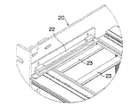
ラック20は、図1および図2に示すように、アルミニウム合金等の金属材料を用いて箱形に形成され、その内部にマザーボード2およびドーターボード3が収容される。ラック20の左右内側部には、互いに対向する一対の第1ガイドレール部材22が設けられている(右方の第1ガイドレール部材は図示省略する)。第1ガイドレール部材22は、図4に示すように、ラック20の前後方向へ延びる断面視凹形(横向き)の形状に形成され、ファン取付板13の左右端を左右の第1ガイドレール部材22の内側にそれぞれ挿入することで、一対の第1ガイドレール部材22にファンユニット10がスライド移動可能に支持されるようになっている。また、ラック20の内側上下には、互いに対向する上下一対の第2ガイドレール部材23が複数配設されており、各ドーターボード3がそれぞれスライド移動可能に支持されるようになっている。
As shown in FIGS. 1 and 2, the
電源ユニット30は、図5に示すように箱形に形成され、ラック20の右側に取り付けられる。電源ユニット30の裏面側には、図示しない電力供給コネクタが後方(すなわち、電源ユニット30の取り付け方向)に向けて配設されており、電源ユニット30をラック20に取り付ける際に、マザーボード2に配設された電源用コネクタ26と嵌合接続するようになっている。
The
マザーボード2は、ラック20の背面(もしくは前面)の形状に合わせた板状に形成され、ラック20の前方を向いた状態でラック20の内部に収容される。図6に示すように、マザーボード2の右方には電源用コネクタ26が前方に向けて配設されており、電源ユニット30の電力供給コネクタ(図示せず)と嵌合接続することにより、電源ユニット30とマザーボード2とが電気的に接続されてマザーボード2に(電源ユニット30から)電力が供給されるようになっている。マザーボード2の中央部には、上下一対のスロット27が前方に向けて複数配設されており、各ドーターボード3に配設された一対の接続端子31(図2を参照)とそれぞれ嵌合接続するようになっている。
The
ドーターボード3は、第2ガイドレール部材23に支持された状態でラック20の右方(左方でもよい)を向いてラック20の内部に収容されており、図2に示すように、ドーターボード3の後端部に配設された一対の接続端子31がマザーボード2の(一対の)スロット27とそれぞれ嵌合接続することにより、マザーボード2に対して略直角の向きでマザーボード2と電気的に接続されるようになっている。これにより、ファンユニット10がラック20の右方を向いてラック20内に収容されたドーターボード3の上方に位置し、各ドーターボード3の間にファンユニット10の風向が合わせられるため、ファンユニット10の作動によりドーターボード3の両面を空気が滞りなく流れることから、ドーターボード3およびマザーボード2、電源ユニット30等を効果的に冷却することができる。
The daughter board 3 is accommodated in the
さて、マザーボード2の上部2箇所には、第2コネクタ25が前方に向けて配設されており、マザーボード2を介して第2コネクタ25と電源ユニット30とが電気的に接続されている。そして、第2コネクタ25が中継基板15の第1コネクタ17と嵌合接続することにより、中継基板15およびマザーボード2を介して冷却ファン11のモータ12と電源ユニット30とが電気的に接続されて、モータ12に電源ユニット30から電力が供給されるようになっている。
Now, the
これにより、第2コネクタ25がマザーボード2に配設され、このマザーボード2を介して第2コネクタ25と電源ユニット30とが電気的に接続されるため、第2コネクタ25に対して別途取付部品やケーブル等を設ける必要がないことから、ラックシステム1の部品点数および組立工数を低減させることができ、ラックシステム1の製造コストを減少させることができる。また、第2コネクタ25と電源ユニット30とを繋ぐケーブルの配線スペースを設ける必要がないため、装置寸法を小さくすることができる。さらに、第2コネクタとして安価なボードTOボード用の時差接触コネクタ(図示せず)を使用することができるため、時差接触機能を有するコネクタを使用する場合のコストを減少させることができる。
As a result, the
以上のように構成されるラックシステム1において、ラック20にファンユニット10を取り付けるには、まず、ファン取付板13の左右端を左右の第1ガイドレール部材22の内側にそれぞれ挿入し、第1ガイドレール部材22にファンユニット10をスライド移動可能に支持させる。そして、ファンユニット10をラック20内部(後方)にスライド移動させ、ファンユニット10(中継基板15)の第1コネクタ17とマザーボード2の第2コネクタ25とを嵌合接続させる。このとき、中継基板15およびマザーボード2を介して冷却ファン11のモータ12と電源ユニット30とが電気的に接続される。このようにしてラック20の上部にファンユニット10が取り付けられると、電源ユニット30からマザーボード2および第2コネクタ25、そして、第1コネクタ17および中継基板15を介してモータ12に電力が供給され、モータ12が作動してファンユニット10によるマザーボード2およびドーターボード3、電源ユニット30等の冷却が行われる。
In the
以上のような構成のラックシステム1によれば、第2コネクタ25がマザーボード2に配設され、このマザーボード2を介して第2コネクタ25と電源ユニット30とが電気的に接続されるため、第2コネクタ25に対して別途取付部品やケーブル等を設ける必要がないことから、ラックシステム1の部品点数および組立工数を低減させることができ、ラックシステム1の製造コストを減少させることができる。また、第2コネクタ25と電源ユニット30とを繋ぐケーブルの配線スペースを設ける必要がないため、装置寸法を小さくすることができる。さらに、第2コネクタとして安価なボードTOボード用の時差接触コネクタ(図示せず)を使用することができるため、時差接触機能を有するコネクタを使用する場合のコストを減少させることができる。
According to the
また、ファンユニット10がドーターボード3の間に風向を合わせてラック20に取り付けられることで、ファンユニット10の作動により空気が滞りなく流れるため、ドーターボード3およびマザーボード2、電源ユニット30等を効果的に冷却することができる。
In addition, since the
なお、上述の実施形態において、ファンユニット10がラック20の上部に取り付けられているが、これに限られるものではなく、例えば、ラックの下部や中央部に取り付けられてもよく、ファンユニットに配設される第1コネクタがマザーボードに配設される第2コネクタと嵌合接続可能であればよい。
In the above-described embodiment, the
また、上述の実施形態において、電源ユニット30がラック20の右側に取り付けられてマザーボード2と電気的に接続されているが、これに限られるものではなく、外部電源をマザーボードと電気的に接続させるようにしてもよい。
In the above-described embodiment, the
1 ラックシステム
2 マザーボード
3 ドーターボード
10 ファンユニット
17 第1コネクタ
20 ラック
25 第2コネクタ
30 電源ユニット
DESCRIPTION OF
Claims (2)
前記ラックの左右内側部の上部に互いに対向して前後に延びる左右一対の第1ガイドレール部材が設けられ、ファン取付板にモータ駆動冷却ファンおよび中継基板を取り付けて構成されたファンユニットが、前記ファン取付板の左右端部を前記第1ガイドレール部材に挿入してガイドされて前記ラック内の上部に横方向に延びて配設され、
前記ラックの内部における前記ファンユニットより下側の空間内において、上下に対向して前後に延びる上下一対の第2ガイドレール部材が複数配設されており、複数のドーターボードがそれぞれ上下端部を前記第2ガイドレール部材に挿入してガイドされて前記ラック内に縦方向に延びて配設され、
電源ユニットが前記ラック内に前記ドーターボードと隣接して挿入配設されており、
前記マザーボードには、前記第1ガイドレール部材にガイドされて挿入されて前記ファンユニットが挿入されたときに前記中継基板の後端に後方に向けて取り付けられた第1コネクタと嵌合接続される第2コネクタと、前記第2ガイドレール部材にガイドされて前記ドーターボードが挿入されたときに前記ドーターボードの後端に配設された接続端子と嵌合接続する複数のスロットと、前記電源ユニットが前記ラック内に挿入配設されたときに前記電源ユニットの裏面側に後方に向けて配設された電力供給コネクタと嵌合接続する電源用コネクタとが設けられており、
前記電源ユニットからの供給電力が前記マザーボートを介して前記ファンユニットの前記中継基板に供給され、前記中継基板から前記モータ駆動冷却ファンに供給されてこれが駆動されるように構成されたことを特徴とするラックシステム。 A rack system in which a mother boat is arranged facing the front on the inner back surface of the rack, which is formed in a plate shape that matches the shape of the back surface of a rectangular box-shaped rack whose front side is open,
A pair of left and right first guide rail members extending in the front-rear direction opposite to each other are provided on the upper left and right inner portions of the rack, and a fan unit configured by mounting a motor-driven cooling fan and a relay board on the fan mounting plate, The left and right ends of the fan mounting plate are guided by being inserted into the first guide rail member, and are arranged extending in the lateral direction at the upper part in the rack.
In the space below the fan unit in the rack, a plurality of upper and lower pairs of second guide rail members extending in the front-rear direction are arranged opposite to each other, and the plurality of daughter boards respectively have upper and lower ends. Inserted into the second guide rail member, guided and extended in the rack in the vertical direction,
A power supply unit is inserted and disposed in the rack adjacent to the daughter board,
The motherboard is fitted and connected to a first connector that is guided by the first guide rail member and is attached to the rear end of the relay board in a rearward direction when the fan unit is inserted. A second connector; a plurality of slots which are fitted and connected to connection terminals disposed at a rear end of the daughter board when the daughter board is inserted by being guided by the second guide rail member; and the power supply unit Is provided with a power supply connector to be fitted and connected to the power supply connector disposed rearward on the back side of the power supply unit when inserted into the rack.
Supply power from the power supply unit is supplied to the relay board of the fan unit via the mother board, and is supplied from the relay board to the motor-driven cooling fan to be driven. And rack system.
In a state where the fan unit is guided by the first guide rail member and extends horizontally in the upper portion of the rack, the motor-driven cooling fan sends cooling air downward, The rack system according to claim 1, wherein the cooling air is configured to flow between a plurality of the daughter boards arranged in a vertical direction .
Priority Applications (1)
| Application Number | Priority Date | Filing Date | Title |
|---|---|---|---|
| JP2003343356A JP4104143B2 (en) | 2003-10-01 | 2003-10-01 | Rack system |
Applications Claiming Priority (1)
| Application Number | Priority Date | Filing Date | Title |
|---|---|---|---|
| JP2003343356A JP4104143B2 (en) | 2003-10-01 | 2003-10-01 | Rack system |
Publications (2)
| Publication Number | Publication Date |
|---|---|
| JP2005109341A JP2005109341A (en) | 2005-04-21 |
| JP4104143B2 true JP4104143B2 (en) | 2008-06-18 |
Family
ID=34537355
Family Applications (1)
| Application Number | Title | Priority Date | Filing Date |
|---|---|---|---|
| JP2003343356A Expired - Lifetime JP4104143B2 (en) | 2003-10-01 | 2003-10-01 | Rack system |
Country Status (1)
| Country | Link |
|---|---|
| JP (1) | JP4104143B2 (en) |
Families Citing this family (6)
| Publication number | Priority date | Publication date | Assignee | Title |
|---|---|---|---|---|
| KR100707514B1 (en) | 2005-12-01 | 2007-04-16 | 부산대학교 산학협력단 | Structure for parallel cluster computer |
| JP5381004B2 (en) * | 2008-10-16 | 2014-01-08 | 富士電機株式会社 | Inverter device |
| KR101625096B1 (en) * | 2015-03-10 | 2016-05-30 | 쉐도우시스템즈(주) | High performance computing system |
| KR101798732B1 (en) * | 2015-12-28 | 2017-12-12 | 엘에스산전 주식회사 | Fan assembly and electric power equipment having the same |
| CN111511139B (en) * | 2020-04-30 | 2021-03-16 | 陇东学院 | Novel electric automatization is with multi-functional maintenance device |
| US20220312622A1 (en) * | 2021-03-25 | 2022-09-29 | Baidu Usa Llc | Server chassis design for high power density electronics thermal management |
-
2003
- 2003-10-01 JP JP2003343356A patent/JP4104143B2/en not_active Expired - Lifetime
Also Published As
| Publication number | Publication date |
|---|---|
| JP2005109341A (en) | 2005-04-21 |
Similar Documents
| Publication | Publication Date | Title |
|---|---|---|
| US7428151B2 (en) | Cooling arrangement | |
| US6533587B1 (en) | Circuit board riser | |
| JP5055139B2 (en) | Image display device | |
| US20060107678A1 (en) | Cooling arrangement | |
| JP2002032153A (en) | Cartridge type server unit and casing for loading the same | |
| KR100360446B1 (en) | Structure of tower type pc | |
| JP5041548B2 (en) | Power control device | |
| JP4104143B2 (en) | Rack system | |
| WO2012141339A1 (en) | Electronic device | |
| KR101667869B1 (en) | Motor driving apparatus | |
| JP2005108969A (en) | Mounting structure of fan unit | |
| KR101718201B1 (en) | Motor driving apparatus | |
| JP2006202822A (en) | Housing for accommodating wiring board | |
| JP2002185169A (en) | Outdoor communication device | |
| JP4159046B2 (en) | Fan unit | |
| CN112527055A (en) | Computer case and computer system | |
| JP2005276920A (en) | Housing for electrical equipment | |
| JP2503838B2 (en) | Electronic device structure | |
| JP4916148B2 (en) | Game electrical parts cooling device | |
| JP2003163480A (en) | Cooling structure of casing of electronic equipment | |
| JPH11112179A (en) | Cooling device of electronic equipment case | |
| JP2004311956A (en) | Apparatus for connecting electronic unit | |
| CN112286859A (en) | Plug-in box for high-density 1U case | |
| JP2002305393A (en) | Cooling structure of electronic apparatus | |
| JP2002374082A (en) | Cooling structure of electronic apparatus |
Legal Events
| Date | Code | Title | Description |
|---|---|---|---|
| A621 | Written request for application examination |
Free format text: JAPANESE INTERMEDIATE CODE: A621 Effective date: 20050608 |
|
| A977 | Report on retrieval |
Free format text: JAPANESE INTERMEDIATE CODE: A971007 Effective date: 20080123 |
|
| A131 | Notification of reasons for refusal |
Free format text: JAPANESE INTERMEDIATE CODE: A131 Effective date: 20080125 |
|
| A521 | Request for written amendment filed |
Free format text: JAPANESE INTERMEDIATE CODE: A523 Effective date: 20080221 |
|
| TRDD | Decision of grant or rejection written | ||
| A01 | Written decision to grant a patent or to grant a registration (utility model) |
Free format text: JAPANESE INTERMEDIATE CODE: A01 Effective date: 20080321 |
|
| A61 | First payment of annual fees (during grant procedure) |
Free format text: JAPANESE INTERMEDIATE CODE: A61 Effective date: 20080324 |
|
| R150 | Certificate of patent or registration of utility model |
Ref document number: 4104143 Country of ref document: JP Free format text: JAPANESE INTERMEDIATE CODE: R150 Free format text: JAPANESE INTERMEDIATE CODE: R150 |
|
| FPAY | Renewal fee payment (event date is renewal date of database) |
Free format text: PAYMENT UNTIL: 20110404 Year of fee payment: 3 |
|
| FPAY | Renewal fee payment (event date is renewal date of database) |
Free format text: PAYMENT UNTIL: 20120404 Year of fee payment: 4 |
|
| R250 | Receipt of annual fees |
Free format text: JAPANESE INTERMEDIATE CODE: R250 |
|
| FPAY | Renewal fee payment (event date is renewal date of database) |
Free format text: PAYMENT UNTIL: 20130404 Year of fee payment: 5 |
|
| R250 | Receipt of annual fees |
Free format text: JAPANESE INTERMEDIATE CODE: R250 |
|
| FPAY | Renewal fee payment (event date is renewal date of database) |
Free format text: PAYMENT UNTIL: 20130404 Year of fee payment: 5 |
|
| FPAY | Renewal fee payment (event date is renewal date of database) |
Free format text: PAYMENT UNTIL: 20140404 Year of fee payment: 6 |
|
| R250 | Receipt of annual fees |
Free format text: JAPANESE INTERMEDIATE CODE: R250 |
|
| R250 | Receipt of annual fees |
Free format text: JAPANESE INTERMEDIATE CODE: R250 |
|
| R250 | Receipt of annual fees |
Free format text: JAPANESE INTERMEDIATE CODE: R250 |
|
| R250 | Receipt of annual fees |
Free format text: JAPANESE INTERMEDIATE CODE: R250 |
|
| R250 | Receipt of annual fees |
Free format text: JAPANESE INTERMEDIATE CODE: R250 |
|
| R250 | Receipt of annual fees |
Free format text: JAPANESE INTERMEDIATE CODE: R250 |
|
| R250 | Receipt of annual fees |
Free format text: JAPANESE INTERMEDIATE CODE: R250 |
|
| R250 | Receipt of annual fees |
Free format text: JAPANESE INTERMEDIATE CODE: R250 |
|
| R250 | Receipt of annual fees |
Free format text: JAPANESE INTERMEDIATE CODE: R250 |
|
| R250 | Receipt of annual fees |
Free format text: JAPANESE INTERMEDIATE CODE: R250 |
|
| R250 | Receipt of annual fees |
Free format text: JAPANESE INTERMEDIATE CODE: R250 |
|
| EXPY | Cancellation because of completion of term |