JP4068187B2 - Optical disc manufacturing method - Google Patents
Optical disc manufacturing method Download PDFInfo
- Publication number
- JP4068187B2 JP4068187B2 JP22852197A JP22852197A JP4068187B2 JP 4068187 B2 JP4068187 B2 JP 4068187B2 JP 22852197 A JP22852197 A JP 22852197A JP 22852197 A JP22852197 A JP 22852197A JP 4068187 B2 JP4068187 B2 JP 4068187B2
- Authority
- JP
- Japan
- Prior art keywords
- adhesive
- film thickness
- disk
- optical disc
- curing
- Prior art date
- Legal status (The legal status is an assumption and is not a legal conclusion. Google has not performed a legal analysis and makes no representation as to the accuracy of the status listed.)
- Expired - Fee Related
Links
Images


Description
【0001】
【発明の属する技術分野】
本発明は、2枚のディスク基板を貼り合わせて光ディスクを製造する方法に関するものである。
【0002】
【従来の技術】
図12は、従来の光ディスク製造方法の各手順を示す模式図であり、ここでは2枚のディスク基板を貼り合わせて光ディスクを製造する。貼り合わせの材料としては、アクリル系の紫外線硬化型の接着剤1を用いるのが一般的である。
【0003】
この従来方法では、まず図12(a)に示すように、接着剤1をディスペンサ2により、1枚のディスク基板3に対し上方から、環状に供給する。つぎに図12(b)に示すように、2枚目のディスク基板4をその上に載せ、図12(c)に示すように、高速回転させて成膜する。しかる後に図12(d)に示すように、露光硬化を行う。
【0004】
【発明が解決しようとする課題】
上記従来の構成では、成膜時において高速回転を行っており、接着剤1は回転時の遠心力により外周方向へ流動拡散する。この場合、内周部では外周部へ向けて接着剤1が広がっていくため、その膜厚は薄くなる一方だが、外周部では内周部からの接着剤供給により、内周部に比べ膜厚は薄くなりにくい。このため、一般的に接着剤層5の膜厚は均等ではなく、外周部がより厚くなる。図2は、このときの状態を表したものであり、外周部(半径40〜50mm)で膜厚の目標範囲(40〜55μm)を越えている。
【0005】
このようにして製造された2層構造の光ディスクにおいては、特に接着剤層5を介して2層の記録を読み取る方式が用いられる場合、接着剤層5の膜厚に対し厳しい精度が要求されている。その理由は、膜厚が所定の範囲を満たしていなければ、接着剤層5を介する2層目の記録を正確に読み取ることができないためである。
【0006】
ちなみに、内周部と外周部との膜厚差を小さくするためには、高速回転の時間を長くとることが有効である。しかし、その場合には、膜厚が全体的に薄くなり、やはり所定の目標範囲から外れてしまう。図2の下方にその様子を示している。
【0007】
本発明は、上記事情に鑑みてなされたものであり、その主たる目的とするところは、記録の読み取り不良を発生させないため、接着剤層の膜厚を所定の範囲で均一にすることができる光ディスク製造方法を提供することである。
【0011】
【課題を解決するための手段】
本発明は、2枚のディスク基板間に接着剤を供給して、重ね合わせられた2枚のディスク基板を回転させることにより接着剤層を形成した後、この接着剤層を硬化させて製造する、接着剤層を介して2層の記録を読み取る方式の光ディスクを製造する方法において、前記接着剤層の形成中に、前記2枚のディスク基板の内の一方側から前記ディスク基板の半径40〜50mmの位置のみに前記ディスク基板の平面と平行な面を有する加圧具を接触させて前記接着剤層を加圧することを特徴とするものである。
【0012】
このような方法では、回転による接着剤層の形成中、回転により必然的に厚くなる外周側の接着剤層の膜厚をディスク基板を介して加圧して押し込み、膜厚が厚くなっている箇所の接着剤をその前後の比較的膜厚の薄い箇所へ流動させる。このため、全体膜厚を目標範囲内に収めるとともに、膜厚の均一性を向上させることができる。この場合、流動中の接着剤層を加圧変形させるため、加圧に要するエネルギは比較的少ないものとなる。
【0013】
その結果、より少ないエネルギで記録の読み取り不良を発生させるおそれの少ない光ディスクを製造することができる。
【0019】
【発明の実施の形態】
以下、添付の図を参照して本発明のいくつかの実施の形態について説明し、本発明の理解に供する。なお、以下の実施の形態は、本発明を具現化した例であって、本発明の技術的範囲を限定する性格のものではない。
【0020】
(実施の形態1)
図1は、本発明の実施の形態1にかかる光ディスク製造方法の各手順を示す模式図である。図1(a)に示すように、接着剤1の供給および高速回転による成膜は従来例と同様である。貼り合わせの材料としては、ここでも、アクリル系の紫外線硬化型の接着剤1を用いる。この接着剤1を、まず、ディスペンサ2により1枚のディスク基板3に対し上方から、環状に供給する。次に図1(b)に示すように、2枚目のディスク基板4をその上に載せ、図1(c)に示すように、高速回転により成膜する。
【0021】
この状態で、接着剤層5の膜厚は、従来例と同様、図2に示すように、半径40〜50mmの位置が最も厚くなっている。つぎに、図1(d)に示すように、半径40〜50mmの位置に環状の突起を有する加圧具6により上方から加圧し、半径40〜50mmの位置での接着剤層5の厚みが4〜10μになるように、貼り合わせディスク7を押さえ込む。押さえ込まれた箇所の接着剤1は、加圧されていないより膜厚の薄い箇所(半径30mm近辺および最外周)へと流動する。押さえ込む時間は、0.1〜1秒であり、その後、加圧を停止し、貼り合わせディスク7を移動し、図1(e)に示すように、紫外線照射機12により露光する。
【0022】
以上による接着剤層5の膜厚は、図1(c)の成膜時点で、最も厚かった半径40〜50mmの位置で薄くなると同時に、その前後(半径30mm近辺および最外周)が厚くなっており、全体的に膜厚の差が小さくなるとともに、全体として、目標範囲(40〜55μm)を確保している。この様子を図3に示した。
【0023】
図4に本実施の形態1にかかる光ディスク製造方法を具現化する装置の概略構成図を示す。図4において、成膜ステージ8と硬化ステージ9とが並設されており、さらに成膜ステージ8の上方には加圧具6が配備されている。この成膜ステージ8は、ディスク吸着プレート10と、高速回転時に振り切られる接着剤1の余剰液を受け止めるフード11とから構成されている。ディスク吸着プレート10は、図示しない吸着源および駆動源によりディスクを吸着し、2000〜3500rpm程度の回転速度で高速回転させることができる。
【0024】
一方、硬化ステージ9は、紫外線照射機12と、貼り合わせディスク7(図1参照)を受けるパレット13と、パレット13を運ぶコンベア14とから構成されている。加圧具6は、図5に示すように、半径40〜50mmの位置に突起6aを有し、この突起6aの位置で貼り合わせディスク7の当該位置を効果的に押し込むことができる。このために、加圧具6は、その突起6aの位置と、膜厚の厚い箇所とが一致するように、成膜ステージ8と同軸上に配置されている。また、加圧具6は、図示しない駆動源により、上下方向に移動できるようになっている。さらに、成膜ステージ8の上下流側には、ディスク基板3、4を移動させるためのハンドリング用部材15が配備されている。
【0025】
成膜ステージ8の上流側にあるハンドリング用部材15により、貼り合わせディスク7は、図1(b)に示すような状態で成膜ステージ8に配置される。成膜ステージ8はディスク基板3を吸着し、図1(c)、(d)に示すようなレベリングおよび加圧を行う。その後、貼り合わせディスク7は下流側のハンドリング用部材15により移動され、パレット13に搭載される。パレット13は、コンベア14により紫外線照射機12の下を通過し、この時、図1(e)に示すような露光硬化が行われる。
【0026】
このように、本実施の形態1によれば、最低膜厚を目標範囲内に確保した状態で最高膜厚を矯正することにより、全体膜厚を目標範囲内に収めるとともに、膜厚をより均等にすることができる。
【0027】
なお、本実施の形態1では、接着剤1を紫外線硬化型としたが、必要な品質が得られれば、他の硬化反応を有する材料を用いてもかまわない。たとえば、熱硬化型や2液反応型の材料を用いてもよい。ただし、その場合には、硬化ステージ9は、紫外線照射機12を有するものではなく、所定の温度に設定された炉などを有するものとなるのはいうまでもない。
【0028】
また、本実施の形態1では、成膜ステージ8に貼り合わせディスク7が、図1(b)の状態で配置されているものとしたが、それ以前の状態であってもかまわない。接着剤1の供給方法や、2枚目のディスク基板4を1枚目のディスク基板3に対向させるタイミングについては、どのように行おうとかまわない。本実施の形態1における成膜の手順(図1(a)〜(c))はあくまで一例であり、他の手順を用いてもよいのはもちろんである。
【0029】
また、本実施の形態1の加圧具6は、直接駆動源に接続されたもので、押し込み量を駆動源により制御するものでもよいが、駆動源とは接続されておらず、加圧具6の自重により押し込み量を決定するものでもよい。また、本実施の形態1では、加圧手段としては、加圧具6を用いたが、他の手段を用いてもかまわない。
【0030】
また、本実施の形態1では、成膜後で硬化前に加圧しているが、成膜中に加圧してもよい。その場合は、流動中の接着剤1の加圧変形を行うこととなり、加圧に要するエネルギは比較的小さくて済む。必要であれば、加圧前に、より低エネルギでの予備硬化を行ってもよい。また、本実施の形態1では、半径方向の位置や膜厚の押し込み量、加圧具6の形状の一例を記したが、必要に応じて、この記した値や形状を変更してもよいのはもちろんである。
【0031】
(実施の形態2)
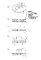
図6は、実施の形態2にかかる光ディスク製造方法の各手順を示す模式図である。本実施の形態2は、図6(a),(b)に示すように、2枚目のディスク基板4を載せるまでは、従来例および上記実施の形態1と同様である。この後、高速回転によるレベリングを行うが、その際図6(c)に示すように、上方より半径45mmの位置を狙って、気体吐出ノズル21を用いて気体の吹き付けによる加圧を行う。加圧なしで回転成膜を行った場合は、従来例と同様、図2に示すような膜厚分布となるが、このように加圧することにより半径45mm近傍の位置での接着剤の流動が規制され、半径45mm近傍での膜厚は薄くなる。この状態で、図6(d)に示すように露光すると、膜厚は、図3に示したものと類似の分布となる。
【0032】
図7は、本実施の形態2を具現化する装置の概略構成図である。図7に示すように、ここでも、成膜ステージ8と硬化ステージ9とが並設されている。さらに、成膜ステージ8上には、気体吐出ノズル21が配備されている。それ以外の成膜ステージ8および硬化ステージ9の構成は、上記実施の形態1の場合と同様である。
【0033】
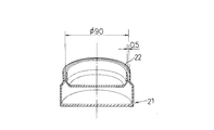
気体吐出ノズル21は、図8に示すように、半径45mmで、幅0.5mmの環状のスリット形状をなす気体吐出口22を有している。気体吐出ノズル21は、気体の吐出位置と膜厚の厚くなるであろう箇所とが一致するように、成膜ステージ8と同軸上に配置されている。また、気体吐出ノズル21は、図示しない駆動源により上下方向に移動可能となっている。成膜ステージ8の上下流側には、ディスク基板を移動させるためのハンドリング用部材15が配備されている。
【0034】
成膜ステージ8の上流側にあるハンドリング用部材15により、貼り合わせディスク7は、図6(b)に示すような状態で成膜ステージ8に配置される。成膜ステージ8は、ディスク基板3を吸着し、図6(c)に示すようにレベリングおよび加圧を行う。この時、気体吐出ノズル21は、ディスク基板4の上面から約100μmの位置で、圧力2〜4kg/cm2 にて気体を吐出する。吐出された気体は、ディスク基板4に対し垂直に、かつ、筒状に吹き付けられ、ディスク基板4の半径45mmの位置を押圧する。この後、貼り合わせディスク7は、下流側のハンドリング用部材15により移動され、パレット13に搭載される。パレット13は、コンベア14により紫外線照射機12の下を通過し、この時、図6(d)に示すように露光硬化が行われる。
【0035】
以上により、本実施の形態2によれば、最低膜厚を目標範囲内に確保しつつ、最高膜厚を規制することにより、全体膜厚を目標範囲内に収めるとともに、膜厚をより均等にすることができる。また、本実施の形態2は、上記実施の形態1と比較して、ディスク基板への加圧手段の接触がないため、基板に傷を付けるおそれがない点で優れている。
【0036】
なお、本実施の形態2では、接着剤1を紫外線硬化型としたが、必要な品質が得られれば、他の反応を有する材料を用いてもよく、この点は、上記実施の形態1の場合と同様である。
【0037】
また、本実施の形態2では、成膜ステージ8に貼り合わせディスク7が、図6(b)に示すような状態で配置されるものとしたが、それ以前の状態であってもかまわない。接着剤1の供給方法や、2枚目のディスク基板4を1枚目のディスク基板3に対向させるタイミングについては、どのように行おうとかまわない点でも、上記実施の形態1の場合と同様である。
【0038】
また、本実施の形態2では、加圧手段として特定形状の気体吐出ノズル21を用いたが、他の形状のものでもかまわない。たとえば、φ0.5mmの吐出口を有するノズルを複数、同心円状に配備してもよい。また、この場合、回転に応じて、時間とともに各ノズルが半径方向に移動し、接着剤1の流動を所定の幅で連続的に制御することも可能である。また、加圧手段として、気体の圧力ではなく、他の手段を用いてもかまわない。
【0039】
また、本実施の形態2では、半径方向の位置や気体の吐出条件の一例を記したが、必要に応じてこの記した値を変更してもよいのはもちろんである。
【0040】
(実施の形態3)
図9は、本発明の実施の形態3にかかる光ディスク製造方法の各手順を示す模式図である。図9(a)〜(c)に示すように、高速回転による成膜までは、従来例および上記実施の形態1と同様である。また、加圧具31の形状も、半径40〜50mmの位置に突起を有し、図5に示したような、上記実施の形態1のもの(加圧具6)と同様である。ただし、ここでの加圧具31は、光透過性を有する材料、たとえば、ガラス材により形成されている。成膜終了後、貼り合わせディスク7上に加圧具31を載せ、図9(d)に示すように、そのまま露光を行う。紫外光は、加圧具31の上方から照射されるが、加圧具31を透過し、接着剤1を硬化させることができる。
【0041】
図10は、本実施の形態3を具現化する装置の概略構成図である。図10に示すように、ここでも、成膜ステージ8と硬化ステージ9とが並設されている。さらに、硬化ステージ9には、加圧具31が複数配備されている。その他の点では、成膜ステージ8および硬化ステージ9は、上記実施の形態1と同様の構成である。また、成膜ステージ8の上下流側には、ディスク基板を移動させるハンドリング用部材15が配備されている。
【0042】
加圧具31は、図4に示した上記実施の形態1の加圧具6と同様の形状であるが、ここでは、上記実施の形態1のように成膜ステージ8上を移動するのではなく、第2のハンドリング用部材32によりパレット13に搭載することができる。
【0043】
図9(b)に示すような状態で、成膜ステージ8に配置された貼り合わせディスク7は、成膜ステージ8において吸着され、図9(c)に示すようにレベリングされる。その後、下流側のハンドリング用部材15により移動され、パレット13に搭載される。さらにこの上に、第2のハンドリング用部材32により加圧具31が同軸上に載せられる。貼り合わせディスク7および加圧具31を載せたパレット13は、コンベア14により紫外線照射機12の下を通過し、この時、図9(d)に示すように露光硬化が行われる。
【0044】
このように本実施の形態3によれば、最低膜厚を目標範囲内に確保しつつ最高膜厚を規制することにより、全体膜厚を目標範囲内に収めるとともに、膜厚をより均等にすることができる。また、本実施の形態3は、上記実施の形態1と比較して、貼り合わせディスク7を加圧したまま露光硬化するため、加圧に要するエネルギは比較的に大きくなるが、より確実に膜厚の均一化を図ることができる点で優れている。
【0045】
なお、本実施の形態3では、接着剤1を紫外線硬化型としたが、必要な品質が得られれば、他の反応を有する材料を用いてもよく、この点は、上記実施の形態1の場合と同様である。
【0046】
また、本実施の形態3では、成膜ステージ8に貼り合わせディスク7が、図9(b)に示すような状態で配置されるとしたが、それ以前の状態であってもかまわない。接着剤1の供給方法や、2枚目のディスク基板4を1枚目のディスク基板3に対向させるタイミングについては、どのように行おうとかまわない点でも、上記実施の形態1の場合と同様である。
【0047】
また、本実施の形態3では、加圧手段として、加圧具31を用いたが、他の手段を用いてもかまわない。また、本実施の形態3では、成膜後で硬化前に加圧しているが、成膜中に加圧してもよい。その場合は、流動中の接着剤1の加圧変形を行うこととなり、加圧に要するエネルギは比較的小さくて済む。必要であれば、加圧前に、より低エネルギでの予備硬化を行ってもよい。また、本実施の形態3では、半径方向の位置や加圧具31の材質について記したが、必要であれば、この記した値や材質を変更してもよいのはいうまでもない。
【0048】
(実施の形態4)
上記実施の形態3では、加圧具31と紫外線照射機12とを別個のものとしたが、加圧具31が紫外線照射機12に接続されたものであってもよい。図11は、そのような特徴を有する、本発明の実施の形態4にかかる装置例の概略構成図である。
【0049】
図11において、紫外線照射機12と光透過性の加圧具31との接続部には、シャッタ41を設けており、必要に応じてこのシャッタ41を開閉動作させる。
【0050】
ここでは、上記実施の形態1におけるようなコンベア14はなく、パレット13は所定位置に固定されており、パレット13と加圧具31とは同軸上に配置されている。加圧具31は、駆動源42により上下方向に移動可能となっている。また、パレット13の周囲および紫外線照射機12と加圧具31との接続部には、露光時に紫外線が周囲に漏れないように、遮光カバー43が配備されている。
【0051】
このような状態での装置の動作について、以下説明する。本実施の形態4においても、貼り合わせディスク7が、成膜ステージ8上で、図9(c)に示すようなレベリングを終了するまでは、従来例および上記実施の形態3と同様である。
【0052】
この後、パレット13上に移動させた貼り合わせディスク7の半径40〜50mmの位置を、加圧具31により4〜10μmだけ押し込む。この時点で、加圧具31上のシャッタ41が開き、露光を行う。紫外線は、遮光カバー43により外部には漏れないようになっている。露光は3秒程度で終了し、シャッタ41が閉まり、加圧具31は上昇する。以上のようにして接着剤1の硬化が完了する。
【0053】
このように、本実施の形態4によれば、最低膜厚を目標範囲内に確保しつつ最高膜厚を規制することにより、全体膜厚を目標範囲内に収めるとともに、膜厚をより均等にすることができる。また、本実施の形態4は、上記実施の形態1と比較して、貼り合わせディスク7を加圧したまま露光硬化するため、より確実に膜厚の均一化を図ることができる。また、本実施の形態4は、上記実施の形態3と比較して、コンベア14が不要であるため、硬化ステージ9の所要スペースを小さくすることができる点で優れている。
【0054】
なお、本実施の形態4では、加圧手段として加圧具31を用いたが、他の手段を用いてもかまわない。また、本実施の形態4では、加圧具31の押圧とシャッタ41の開閉とのタイミングについて指定したが、必要であれば、この逆のタイミングにしてもよい。たとえば、シャッタ41を開き、接着剤1を硬化させながら加圧具31を押し込んでもかまわない。また、本実施の形態4では、半径方向の位置や膜厚の押し込み量、加圧具31の材質について記したが、必要であれば、この記した値や材質を変更してもよいのはいうまでもない。
【0055】
【発明の効果】
以上の説明から明らかなように、本発明によれば、回転による成膜後、回転により必然的に厚くなる外周側の膜厚を加圧具により押し込み、膜厚が厚くなっている箇所の接着剤をその前後の比較的膜厚の薄い箇所へ流動させる。このため、全体膜厚を目標範囲内に収めるとともに、膜厚の均一性を向上させることができる。
【0056】
その結果、記録の読み取り不良の発生のおそれの少ない光ディスクを製造することができる。
【図面の簡単な説明】
【図1】本発明の実施の形態1にかかる光ディスク製造方法の各手順を示す模式図である。
【図2】加圧前の膜厚分布を示す説明図である。
【図3】加圧後の膜厚分布を示す説明図である。
【図4】実施の形態1にかかる光ディスク製造方法を適用可能な装置の概略構成図である。
【図5】実施の形態1における加圧具の概念図である。
【図6】本発明の実施の形態2にかかる光ディスク製造方法の各手順を示す模式図である。
【図7】実施の形態2にかかる光ディスク製造方法を適用可能な装置の概略構成図である。
【図8】実施の形態2における気体吐出ノズルの概念図である。
【図9】本発明の実施の形態3にかかる光ディスク製造方法の各手順を示す模式図である。
【図10】実施の形態3にかかる光ディスク製造方法を適用可能な装置の概略構成図である。
【図11】実施の形態4における硬化ステージの概念図である。
【図12】従来光ディスク製造方法の一例における各手順を示す模式図である。
【符号の説明】
1 接着剤
2 ディスペンサ
3 ディスク基板(下側)
4 ディスク基板(上側)
5 接着剤層
6 加圧具
7 貼り合わせディスク
8 成膜ステージ
9 硬化ステージ
10 吸着プレート
11 フード
12 紫外線照射機
13 パレット
14 コンベア
15 ハンドリング用部材
21 気体吐出ノズル
22 気体吐出口
31 加圧具
32 第2のハンドリング用部材
41 シャッタ
42 駆動源
43 遮光カバー[0001]
BACKGROUND OF THE INVENTION
The present invention, by bonding two disc substrates in which relates to how to manufacture the optical disc.
[0002]
[Prior art]
FIG. 12 is a schematic diagram showing each procedure of a conventional optical disk manufacturing method. Here, an optical disk is manufactured by bonding two disk substrates together. As a material for bonding, an acrylic ultraviolet
[0003]
In this conventional method, first, as shown in FIG. 12A, the
[0004]
[Problems to be solved by the invention]
In the conventional configuration described above, high-speed rotation is performed during film formation, and the adhesive 1 flows and diffuses in the outer circumferential direction due to centrifugal force during rotation. In this case, since the
[0005]
In the optical disc having the two-layer structure manufactured as described above, strict accuracy is required for the thickness of the
[0006]
Incidentally, in order to reduce the film thickness difference between the inner peripheral portion and the outer peripheral portion, it is effective to take a long time for high-speed rotation. However, in that case, the film thickness becomes thinner as a whole, which is also out of the predetermined target range. This is shown in the lower part of FIG.
[0007]
The present invention has been made in view of the above circumstances, and the main object of the present invention is to prevent the occurrence of defective reading of recording, so that the thickness of the adhesive layer can be made uniform within a predetermined range. it is to provide a manufacturing how.
[0011]
[Means for Solving the Problems]
This onset Ming supplies an adhesive between two disk substrates, the two disk substrates which are superposed after formation of the adhesive layer by rotating, by curing the adhesive layer In the method of manufacturing an optical disk of a type that reads a two-layer record through an adhesive layer, a radius of the disk substrate from one side of the two disk substrates is formed during the formation of the adhesive layer. A pressure tool having a surface parallel to the plane of the disk substrate is brought into contact only at a position of 40 to 50 mm to pressurize the adhesive layer.
[0012]
In this manner, during the formation of the adhesive layer by rotating, the film thickness of the necessarily thickened outer peripheral side of the adhesive layer by rotary pushing pressurized through the disk substrate, the film thickness is thicker The adhesive at the location is caused to flow to locations where the film thickness is relatively thin. For this reason, while keeping the whole film thickness in the target range, the uniformity of the film thickness can be improved. In this case, since the adhesive layer that is flowing is subjected to pressure deformation, the energy required for pressure application is relatively small.
[0013]
As a result, it is possible to manufacture an optical disc that is less likely to cause a recording reading failure with less energy.
[0019]
DETAILED DESCRIPTION OF THE INVENTION
Hereinafter, several embodiments of the present invention will be described with reference to the accompanying drawings to help understand the present invention. The following embodiments are examples embodying the present invention, and are not of a nature that limits the technical scope of the present invention.
[0020]
(Embodiment 1)
FIG. 1 is a schematic diagram showing each procedure of the optical disc manufacturing method according to the first embodiment of the present invention. As shown in FIG. 1A, the supply of the
[0021]
In this state, the thickness of the
[0022]
The film thickness of the
[0023]
FIG. 4 is a schematic configuration diagram of an apparatus that embodies the optical disc manufacturing method according to the first embodiment. In FIG. 4, a
[0024]
On the other hand, the curing
[0025]
With the handling
[0026]
As described above, according to the first embodiment, by correcting the maximum film thickness while ensuring the minimum film thickness within the target range, the overall film thickness is kept within the target range and the film thickness is more uniform. Can be.
[0027]
In the first embodiment, the adhesive 1 is an ultraviolet curable type, but other materials having a curing reaction may be used as long as necessary quality is obtained. For example, a thermosetting material or a two-component reaction type material may be used. However, in that case, it goes without saying that the curing
[0028]
In the first embodiment, the
[0029]
Further, the pressurizing
[0030]
In the first embodiment, the pressure is applied after the film formation and before the curing, but the pressure may be applied during the film formation. In this case, the adhesive 1 that is flowing is subjected to pressure deformation, and the energy required for the pressure is relatively small. If necessary, pre-curing with lower energy may be performed before pressurization. Moreover, in this
[0031]
(Embodiment 2)
FIG. 6 is a schematic diagram illustrating each procedure of the optical disc manufacturing method according to the second embodiment. As shown in FIGS. 6A and 6B, the second embodiment is the same as the conventional example and the first embodiment until the
[0032]
FIG. 7 is a schematic configuration diagram of an apparatus that embodies the second embodiment. As shown in FIG. 7, the
[0033]
As shown in FIG. 8, the
[0034]
With the handling
[0035]
As described above, according to the second embodiment, by restricting the maximum film thickness while ensuring the minimum film thickness within the target range, the entire film thickness can be kept within the target range and the film thickness can be made more uniform. can do. Further, the second embodiment is superior to the first embodiment in that there is no possibility of scratching the substrate because there is no contact of the pressing means to the disk substrate.
[0036]
In the second embodiment, the adhesive 1 is an ultraviolet curable type. However, a material having another reaction may be used as long as necessary quality is obtained. This point is the same as that of the first embodiment. Same as the case.
[0037]
In the second embodiment, the
[0038]
In the second embodiment, the
[0039]
In the second embodiment, an example of the radial position and gas discharge conditions is described, but it is needless to say that the described values may be changed as necessary.
[0040]
(Embodiment 3)
FIG. 9 is a schematic diagram showing each procedure of the optical disc manufacturing method according to the third embodiment of the present invention. As shown in FIGS. 9A to 9C, the processes up to film formation by high-speed rotation are the same as those in the conventional example and the first embodiment. Moreover, the shape of the pressurizing
[0041]
FIG. 10 is a schematic configuration diagram of an apparatus that embodies the third embodiment. As shown in FIG. 10, the
[0042]
The pressurizing
[0043]
In the state shown in FIG. 9B, the
[0044]
As described above, according to the third embodiment, by restricting the maximum film thickness while ensuring the minimum film thickness within the target range, the overall film thickness is within the target range and the film thickness is made more uniform. be able to. Further, in the third embodiment, compared with the first embodiment, since the exposure and curing is performed with the bonded
[0045]
In the third embodiment, the adhesive 1 is an ultraviolet curable type. However, a material having another reaction may be used as long as necessary quality is obtained. This point is the same as that of the first embodiment. Same as the case.
[0046]
In the third embodiment, the
[0047]
In the third embodiment, the pressurizing
[0048]
(Embodiment 4)
In the third embodiment, the pressurizing
[0049]
In FIG. 11, a
[0050]
Here, there is no
[0051]
The operation of the apparatus in such a state will be described below. Also in the fourth embodiment, the same process as that of the conventional example and the third embodiment is performed until the
[0052]
Thereafter, the position of the
[0053]
As described above, according to the fourth embodiment, by restricting the maximum film thickness while ensuring the minimum film thickness within the target range, the overall film thickness can be kept within the target range and the film thickness can be made more uniform. can do. Further, in the fourth embodiment, compared to the first embodiment, the film is exposed and cured while the bonded
[0054]
In the fourth embodiment, the pressurizing
[0055]
【The invention's effect】
As apparent from the above description, according to the present invention, after the film formation by rotation, the thickness of the naturally thickened outer peripheral side pressure again and again pushing more the rotation position where the film thickness is thicker The adhesive is allowed to flow to relatively thin portions before and after the adhesive. For this reason, while keeping the whole film thickness in the target range, the uniformity of the film thickness can be improved.
[0056]
As a result, it is possible to manufacture an optical disc that is less likely to cause a recording read failure.
[Brief description of the drawings]
FIG. 1 is a schematic diagram showing each procedure of an optical disc manufacturing method according to a first embodiment of the present invention.
FIG. 2 is an explanatory diagram showing a film thickness distribution before pressurization.
FIG. 3 is an explanatory diagram showing a film thickness distribution after pressurization.
FIG. 4 is a schematic configuration diagram of an apparatus to which the optical disc manufacturing method according to the first embodiment can be applied.
5 is a conceptual diagram of a pressurizing tool according to
FIG. 6 is a schematic diagram showing each procedure of the optical disc manufacturing method according to the second embodiment of the present invention.
FIG. 7 is a schematic configuration diagram of an apparatus to which the optical disc manufacturing method according to the second embodiment can be applied.
FIG. 8 is a conceptual diagram of a gas discharge nozzle in the second embodiment.
FIG. 9 is a schematic diagram showing each procedure of the optical disc manufacturing method according to the third embodiment of the present invention.
FIG. 10 is a schematic configuration diagram of an apparatus to which the optical disc manufacturing method according to the third embodiment can be applied.
FIG. 11 is a conceptual diagram of a curing stage in the fourth embodiment.
FIG. 12 is a schematic diagram showing each procedure in an example of a conventional optical disc manufacturing method.
[Explanation of symbols]
1 Adhesive 2
4 Disc board (upper side)
5
Claims (1)
前記接着剤層の形成中に、前記2枚のディスク基板の内の一方側から前記ディスク基板の半径40〜50mmの位置のみに前記ディスク基板の平面と平行な面を有する加圧具を接触させて前記接着剤層を加圧することを特徴とする光ディスク製造方法。Supplying an adhesive between two disk substrates, after forming the adhesive layer by the two disk substrates which are superposed thereby rotating, it is produced by curing the adhesive layer, the adhesive In a method of manufacturing an optical disc of a method of reading a two-layer record through a layer ,
During the formation of the adhesive layer, a pressure tool having a plane parallel to the plane of the disk substrate is brought into contact only with a radius of 40 to 50 mm of the disk substrate from one side of the two disk substrates. And pressurizing the adhesive layer.
Priority Applications (1)
| Application Number | Priority Date | Filing Date | Title |
|---|---|---|---|
| JP22852197A JP4068187B2 (en) | 1997-08-25 | 1997-08-25 | Optical disc manufacturing method |
Applications Claiming Priority (1)
| Application Number | Priority Date | Filing Date | Title |
|---|---|---|---|
| JP22852197A JP4068187B2 (en) | 1997-08-25 | 1997-08-25 | Optical disc manufacturing method |
Publications (2)
| Publication Number | Publication Date |
|---|---|
| JPH1166644A JPH1166644A (en) | 1999-03-09 |
| JP4068187B2 true JP4068187B2 (en) | 2008-03-26 |
Family
ID=16877732
Family Applications (1)
| Application Number | Title | Priority Date | Filing Date |
|---|---|---|---|
| JP22852197A Expired - Fee Related JP4068187B2 (en) | 1997-08-25 | 1997-08-25 | Optical disc manufacturing method |
Country Status (1)
| Country | Link |
|---|---|
| JP (1) | JP4068187B2 (en) |
Families Citing this family (4)
| Publication number | Priority date | Publication date | Assignee | Title |
|---|---|---|---|---|
| US6312549B1 (en) | 1999-03-10 | 2001-11-06 | Global Machinery Co., Ltd. | Optical disk pasting apparatus and method for pasting optical disks |
| JP3516632B2 (en) * | 2000-04-27 | 2004-04-05 | オリジン電気株式会社 | Method and apparatus for bonding optical disk substrates |
| KR20010104034A (en) * | 2000-05-12 | 2001-11-24 | 정광훈 | making of adhesion method used centrifugal forece for D.V.D disc |
| US7460463B2 (en) * | 2002-05-10 | 2008-12-02 | Panasonic Corporation | Method of and apparatus for manufacturing multi-layer optical information recording medium |
-
1997
- 1997-08-25 JP JP22852197A patent/JP4068187B2/en not_active Expired - Fee Related
Also Published As
| Publication number | Publication date |
|---|---|
| JPH1166644A (en) | 1999-03-09 |
Similar Documents
| Publication | Publication Date | Title |
|---|---|---|
| EP1120781B1 (en) | Apparatus for manufacture of laminated optical discs | |
| US8088438B2 (en) | Resin layer formation method, resin layer formation device, and disk manufacturing method | |
| TWI384476B (en) | Fitting method and fitting device | |
| JP4463696B2 (en) | Optical disc manufacturing method and apparatus | |
| JP4068187B2 (en) | Optical disc manufacturing method | |
| JPH09265672A (en) | Laminating method of optical disk and laminating device | |
| JP4106401B2 (en) | Method and apparatus for manufacturing optical bonded disc | |
| WO2003028024A1 (en) | Method for producing multilayer optical recording medium and system for producing multilayer optical recording medium | |
| JPH10275362A (en) | Optical stuck disk and molding die therefor | |
| JP2003099991A (en) | Method and device for manufacturing optical recording medium | |
| JP4130200B2 (en) | Laminated optical disk manufacturing equipment | |
| JP3637759B2 (en) | Substrate bonding method and apparatus | |
| JP4668096B2 (en) | Resin layer forming apparatus and resin layer forming method | |
| JPH09147430A (en) | Production of information recording disk and apparatus therefor | |
| JPH09297942A (en) | Sticking method for optical disk and its device | |
| JP4535409B2 (en) | Spinner | |
| JPH11283287A (en) | Production of laminated disk, and sticking device to be used therefor | |
| JP3938254B2 (en) | Substrate bonding method and apparatus | |
| JP4557234B2 (en) | Manufacturing method of composite substrate | |
| JP2002067169A (en) | Device and method for pasting | |
| JP3841144B2 (en) | Information recording medium manufacturing method and manufacturing apparatus | |
| JP2003059119A (en) | Method of sticking together stuck type optical media and apparatus for sticking together stuck type optical media | |
| JP2005002274A (en) | Method for attaching organic film to substrate and attaching apparatus | |
| JPS632133A (en) | Production of optical information recording carrier | |
| JPH10302317A (en) | Optical stuck disk and its production |
Legal Events
| Date | Code | Title | Description |
|---|---|---|---|
| A521 | Written amendment |
Free format text: JAPANESE INTERMEDIATE CODE: A523 Effective date: 20040823 |
|
| A621 | Written request for application examination |
Free format text: JAPANESE INTERMEDIATE CODE: A621 Effective date: 20040823 |
|
| A977 | Report on retrieval |
Free format text: JAPANESE INTERMEDIATE CODE: A971007 Effective date: 20051115 |
|
| A131 | Notification of reasons for refusal |
Free format text: JAPANESE INTERMEDIATE CODE: A131 Effective date: 20060530 |
|
| A521 | Written amendment |
Free format text: JAPANESE INTERMEDIATE CODE: A523 Effective date: 20060728 |
|
| TRDD | Decision of grant or rejection written | ||
| A01 | Written decision to grant a patent or to grant a registration (utility model) |
Free format text: JAPANESE INTERMEDIATE CODE: A01 Effective date: 20071211 |
|
| A61 | First payment of annual fees (during grant procedure) |
Free format text: JAPANESE INTERMEDIATE CODE: A61 Effective date: 20080110 |
|
| FPAY | Renewal fee payment (event date is renewal date of database) |
Free format text: PAYMENT UNTIL: 20110118 Year of fee payment: 3 |
|
| R150 | Certificate of patent or registration of utility model |
Free format text: JAPANESE INTERMEDIATE CODE: R150 |
|
| FPAY | Renewal fee payment (event date is renewal date of database) |
Free format text: PAYMENT UNTIL: 20110118 Year of fee payment: 3 |
|
| FPAY | Renewal fee payment (event date is renewal date of database) |
Free format text: PAYMENT UNTIL: 20120118 Year of fee payment: 4 |
|
| LAPS | Cancellation because of no payment of annual fees |