JP4061999B2 - Exhaust gas purification device for internal combustion engine - Google Patents
Exhaust gas purification device for internal combustion engine Download PDFInfo
- Publication number
- JP4061999B2 JP4061999B2 JP2002208976A JP2002208976A JP4061999B2 JP 4061999 B2 JP4061999 B2 JP 4061999B2 JP 2002208976 A JP2002208976 A JP 2002208976A JP 2002208976 A JP2002208976 A JP 2002208976A JP 4061999 B2 JP4061999 B2 JP 4061999B2
- Authority
- JP
- Japan
- Prior art keywords
- exhaust
- trap
- air
- fuel ratio
- particulate trap
- Prior art date
- Legal status (The legal status is an assumption and is not a legal conclusion. Google has not performed a legal analysis and makes no representation as to the accuracy of the status listed.)
- Expired - Fee Related
Links
Images


Classifications
-
- Y—GENERAL TAGGING OF NEW TECHNOLOGICAL DEVELOPMENTS; GENERAL TAGGING OF CROSS-SECTIONAL TECHNOLOGIES SPANNING OVER SEVERAL SECTIONS OF THE IPC; TECHNICAL SUBJECTS COVERED BY FORMER USPC CROSS-REFERENCE ART COLLECTIONS [XRACs] AND DIGESTS
- Y02—TECHNOLOGIES OR APPLICATIONS FOR MITIGATION OR ADAPTATION AGAINST CLIMATE CHANGE
- Y02T—CLIMATE CHANGE MITIGATION TECHNOLOGIES RELATED TO TRANSPORTATION
- Y02T10/00—Road transport of goods or passengers
- Y02T10/10—Internal combustion engine [ICE] based vehicles
- Y02T10/40—Engine management systems
Description
【0001】
【発明の属する技術分野】
この発明は、ディーゼルエンジンに代表される内燃機関において、排気微粒子を捕集する排気微粒子トラップを備えた内燃機関の排気浄化装置に関し、特に、その再生時の割れや溶損を防止する技術に関する。
【0002】
【従来の技術】
内燃機関として例えばディーゼルエンジンでは、排気中の排気微粒子(いわゆるPM)の処理が大きな問題となっており、排気通路に排気微粒子トラップを配置して排気微粒子を捕集するとともに、捕集された排気微粒子が所定レベルに達した段階で排気微粒子を燃焼除去して排気微粒子トラップを再生する排気浄化装置が種々検討されている。
【0003】
特開2001−254616号公報においては、排気微粒子トラップに捕集された排気微粒子を燃焼除去して排気微粒子トラップを再生する必要がある場合に、主噴射終了後の膨張行程又は排気行程中に燃料噴射弁からポスト噴射を行って排気微粒子の燃焼を促進しているが、再生中の排気微粒子トラップの温度を監視し、排気微粒子トラップの温度が所定値以上でかつ温度変化率が所定値以上であれば、この再生操作を停止するようにしている。
【0004】
また、特開平8−319819号公報では、エンジンが高回転高負荷で運転されていて排気温度が600℃を超える状態から、アイドリング等の排気微粒子の急速燃焼が発生するような運転状態に変化した場合には、EGRを通常時よりも増量することで、過度の温度上昇の回避を図っている。
【0005】
【発明が解決しようとする課題】
しかし、上記の特開2001−254616号公報のように、排気微粒子トラップの温度が所定値以上でかつ温度変化率が所定値以上のときにポスト噴射を停止して再生操作を停止したとしても、排気微粒子トラップへ流入する排気の温度は低下するが、逆に排気空燃比が大きくなって排気微粒子の燃焼を促進する酸素濃度が高くなる。そのため、一度着火した排気微粒子の再燃焼を停止させることはできずに、排気微粒子の再燃焼が継続され、前述した排気微粒子の急速燃焼が発生する運転条件変化があると、排気微粒子トラップ内部で局部的に高温となる虞がある。従って、排気微粒子トラップの割れや溶損を十分に防止することができない。
【0006】
また、特開平8−319819号公報の技術では、排気微粒子の急速燃焼が発生するような運転状態に変化した場合には、EGRを通常時よりも増量するようにしている。このようにEGRを増量して酸素濃度を減少させることは、一見して排気微粒子の再燃焼を抑制するように思えるが、実際はEGRを増量することで排気温度が上昇し、かつ排気系からのEGRガスの取り出しにより排気微粒子トラップに流入する排気流量が減少して排気微粒子トラップから持ち出される熱量が減少するので、逆に排気微粒子の燃焼により排気微粒子トラップ温度が上昇しやすい条件を作り出してしまう。従って、特開2001−254616号公報と同様に、排気微粒子トラップの割れや溶損を十分に防止することができない。
【0007】
【課題を解決するための手段】
この発明に係る内燃機関の排気浄化装置においては、内燃機関の排気通路に、流入する排気成分を酸化浄化する酸化触媒が配置され、さらにその下流側に、流入する排気微粒子をトラップする排気微粒子トラップが配置される。そして、酸化触媒と排気微粒子トラップとの間に、さらにNOxトラップ触媒が配置される。また、酸化触媒をNOxトラップ触媒と一体化させることも可能である。
【0008】
また本発明では、上記排気微粒子トラップの温度を検出する温度検出手段と、上記排気微粒子トラップにトラップされた排気微粒子の燃焼速度を検出する燃焼速度検出手段と、膨張行程ないしは排気行程で燃料を噴射するポスト噴射を可能とする燃料噴射手段と、を備えている。そして、上記排気微粒子トラップの温度が所定温度を超え、かつ、上記排気微粒子の燃焼速度が所定速度を超えたときに、上記ポスト噴射によって排気空燃比をリッチにする排気空燃比制御手段を備えている。
【0009】
上記のようにポスト噴射によって排気空燃比がリッチとなると、内燃機関から排出された排気中の酸素が、酸化触媒によって、ポスト噴射により生成された未燃のHCやCOと反応し、排気微粒子トラップに流入する排気中の酸素量(排気の酸素濃度)がほぼ0となる。そのため、排気微粒子の燃焼が止められ、排気微粒子トラップの過度の温度上昇が抑制される。
【0010】
また、排気空燃比制御手段として、ポスト噴射のほか、内燃機関への吸入空気量の減少、排気還流量の増加、の手段を利用することもできる。
【0011】
【発明の効果】
本発明によれば、排気微粒子トラップの再生操作の有無によらず、排気微粒子トラップに捕集された排気微粒子の着火燃焼が開始され、排気微粒子の再燃焼が急速に進むような排気条件の変化が発生したようなときでも、排気微粒子の燃焼速度を確実に抑制して排気微粒子トラップ温度が急上昇することを防止することができる。従って、排気微粒子トラップの割れや溶損を確実に防止できる。
【0012】
【発明の実施の形態】
以下、この発明の好ましい実施の形態を図面に基づいて詳細に説明する。
【0013】
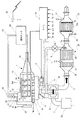
図1は本発明の第1実施例に係る排気浄化装置のシステム構成図である。
【0014】
図1において、1はディーゼルエンジン(以下、単にエンジンと記述する)を示し、3はこのエンジン1の排気通路を示す。
【0015】
本実施例は、#1〜#4の4つの気筒を有するとともに、着火順番が#1−#3−#4−#2となる4気筒直列配置のエンジン1に本発明を適用した例であり、着火順序が連続しないように、#2気筒と#3気筒とからなる気筒群Aと、#1気筒と#4気筒からなる気筒群Bとに、4つの気筒が分けられ、それぞれに排気系の上流側部分が接続されている。
【0016】
なお、このように気筒群を#2,#3気筒からなる気筒群Aと、#1,#4気筒からなる気筒群Bとに分割した理由は、排気行程の干渉によって排気効率が低下し、空気の充填効率が低下するのを抑制するようにしたためであり、排気系のレイアウトを優先する場合には、気筒群Aを#1,#2気筒とし、気筒群Bを#3,#4気筒とすることもできる。
【0017】
このほか、例えば、着火順番が#1−#5−#3−#6−#2−#4の6気筒直列のエンジンで排気干渉抑制を考慮する場合は、気筒群Aを#1,#2,#3気筒とし、気筒群Bを#4,#5,#6気筒とする。なお、本発明で「気筒群」とは、1つ以上の気筒から構成されるものであり、必ずしも複数の気筒を含む必要はない。
【0018】
エンジン1の排気ポートに接続される排気通路3の上流側部分は、排気通路3aと排気通路3bとの2系統に分かれており、気筒群Aの排気ポートが排気通路3aに、気筒群Bの排気ポートが排気通路3bに接続される。両通路3a,3bは、下流の合流部3cにおいて、互いに合流する。なお、各通路3a,3bの上流側部分は、それぞれ気筒数に対応した一対の排気管として構成されている。
【0019】
気筒群Aに対応した排気通路3aには、第1の触媒ケーシング20aが介装されている。この第1の触媒ケーシング20aの内部には、流入する排気成分を酸化浄化する第1の酸化触媒21aと、流入する排気の排気空燃比がリーンであるときにNOxを吸収し、流入する排気の酸素濃度を低下させるとNOxを放出する第1のNOxトラップ触媒22aと、が順に配置されている。つまり、NOxトラップ触媒22aの上流に酸化触媒21aが位置している。同様に、気筒群Bに対応した排気通路3bには、第2の触媒ケーシング20bが介装されており、その内部に、第2の酸化触媒21bと、第2のNOxトラップ触媒22bと、が順に配置されている。
【0020】
また、第1の触媒ケーシング20aと第2の触媒ケーシング20bの下流の合流部3cで、両通路3a,3bが合流しているが、この合流部3cのすぐ下流に、ターボ過給機のタービン3dが接続されている。そして、タービン3dの下流に、排気微粒子トラップ23aを内部に備えたケーシング23が直列に配置されている。
【0021】
上記の酸化触媒21a,21bとしては、例えば活性アルミナをベースにPdやPt等の貴金属を担持したものや、活性アルミナをベースにPdやPt等の貴金属とゼオライトを混合して担持したもの、貴金属(特にPt)をイオン交換したゼオライト、またはこれらの材料を組み合せたもの、が利用できる。
【0022】
また上記排気微粒子トラップ23aとしては、公知のウオールフローハニカムタイプのものや、筒の部分に多数の孔を設けた有底円筒状の芯部材にセラミックファイバを幾層にも巻き回したもの、などが利用でき、捕集した排気微粒子の再燃焼を促進させるために、前述のような酸化触媒を排気微粒子トラップ23aの表面に担持するのが望ましい。
【0023】
上記NOxトラップ触媒22a,22bのそれぞれの入口部には、これらの入口部(酸化触媒21a,21bの出口部)の排気温度(T1a,T1b)を検出する排温センサ36a,36bがそれぞれ設けられている。上記排気微粒子トラップ23aの入口部には、排気圧力P1を検出する排気圧力センサ38が設けられ、また出口部には、排気温度T2を検出する排温センサ37が設けられている。
【0024】
吸気通路2の吸気コレクタ2cと排気通路3bとの間には、排気の一部を還流するためのEGR通路4が設けられ、ここに、ステッピングモータにて開度が連続的に可変制御可能なEGR弁5が介装されている。このEGR弁5の開度は、エンジンコントロールユニット30によって制御される。
【0025】
吸気通路2は、上流位置にエアクリーナ2aを備え、その下流に、過給機のコンプレッサ2bが配置されている。また、アクチュエータ(例えばステッピングモータ式)によって開閉駆動される吸気絞り弁6が吸気コレクタ2cの上流側に配置されている。この吸気絞り弁6の開度は、エンジンコントロールユニット30によって制御される。
【0026】
上記のEGRおよび吸気絞り弁6は、請求項3の「空気量制御手段」に相当する。
【0027】
エンジン1の燃料供給系は、ディーゼル用燃料である軽油を蓄える燃料タンク60と、燃料をエンジン1の燃料噴射装置10へ供給するための燃料供給通路16と、エンジン1の燃料噴射装置10からのリターン燃料(スピル燃料)を燃料タンク60に戻すための燃料戻り通路19と、を備えている。
【0028】
このエンジン1の燃料噴射装置10は、公知のコモンレール式燃料噴射装置であって、サプライポンプ11と、コモンレール(蓄圧室)14と、気筒毎に設けられた燃料噴射弁15と、から大略構成され、サプライポンプ11により加圧された燃料が燃料供給通路12を介してコモンレール14にいったん蓄えられたあと、コモンレール14内の高圧燃料が各気筒の燃料噴射弁15に分配される。
【0029】
またコモンレール14の圧力を制御するために、サプライポンプ11からの吐出燃料の一部が、一方向弁18を具備したオーバーフロー通路17を介して燃料供給通路16に戻されるようになっている。詳しくは、オーバーフロー通路17の流路面積を変える圧力制御弁13が設けられており、この圧力制御弁13がコントロールユニット30からのデューティ信号に応じてオーバーフロー通路17の流路面積を変化させる。これにより、サプライポンプ11からコモンレール14への実質的な燃料吐出量が調整され、コモンレール14の圧力が制御される。
【0030】
燃料噴射弁15は、エンジンコントロールユニット30からのON−OFF信号によって開閉される電子式の噴射弁であって、ON信号によって燃料を燃焼室に噴射し、OFF信号によって噴射を停止する。そして、燃料噴射弁15へ印加されるON信号の期間が長いほど燃料噴射量が多くなり、またコモンレール14の燃料圧力が高いほど燃料噴射量が多くなる。この燃料噴射弁15の噴射期間つまりON信号の期間およびコモンレール14の燃料圧力は、エンジンコントロールユニット30によって制御される。
【0031】
エンジンコントロールユニット30には、水温センサ31の信号(水温Tw)、クランク角度検出用クランク角センサ32の信号(エンジン回転数Neの基礎となるクランク角度信号)、気筒判別用クランク角センサ33の信号(気筒判別信号Cyl)、コモンレール14の圧力を検出する圧力センサ34の信号(コモンレール圧力PCR)、負荷に相当するアクセルペダルの踏み込み量を検出するアクセル開度センサ35の信号(アクセル開度(負荷)L)、がそれぞれ入力される。また、前述したNOxトラップ触媒22a,22bの入口部における排温センサ36a,36bの信号(T1a,T1b)、排気微粒子トラップ23aの出口部における排温センサ37の信号(T2)、排気微粒子トラップ23aの入口部の排気圧力を検出する排気圧力センサ38の信号(P1)、もそれぞれ入力される。
【0032】
次に、上記エンジンコントロールユニット30によって実行される排気浄化装置の制御の内容を、図3〜図l1のフローチャートに基づいて説明する。
【0033】
図3は、ディーゼルエンジン1全体の制御に関する基本制御ルーチンである。
【0034】
このエンジン基本制御ルーチンにおいて、ステップ100では、水温Tw、エンジン回転数Ne、気筒判別信号Cyl、コモンレール圧力PCR、アクセル開度(負荷)L、第1の酸化触媒21aの出口部(第1のNOxトラップ触媒22aの入口部)の排気温度T1a、第2の酸化触媒21bの出口部(第2のNOxトラップ触媒22bの入口部)の排気温度T1b、排気微粒子トラップ23aの入口部の排気圧力P1ならびに出口部の排気温度T2、をそれぞれ読み込み、ステップ200に進む。
【0035】
ステップ200では、コモンレール燃料噴射制御(コモンレール圧力制御、エンジン出力制御のための主噴射制御)を行う。本発明では、コモンレール燃料噴射制御そのものは要部ではないので、簡単に説明する。
【0036】
コモンレール燃料噴射制御は、エンジン回転数Neと主燃料噴射量(負荷Lに対応して予め設定される)Qmainとをパラメータとして、コントロールユニット30のROMに予め記憶されている所定のマップを検索し、コモンレール14の目標基準圧力PCR0を求め、この目標基準圧力PCR0が得られるように圧力制御弁13のフィードバック制御を実行する。
【0037】
そして、主燃料噴射量Qmainが得られるように、主燃料噴射量Qmainとコモンレール圧力PCRとをパラメータとして、コントロールユニット30のROMに予め記憶されている所定のマップを検索し、主噴射開始時期Mstartと主噴射期間Mperiod(msec)とを求め、クランク角度検出用クランク角センサ32のクランク角度信号(Ne)および気筒判別用クランク角センサ33の気筒判別信号(Cyl)に基づいて、上記の主噴射開始時期MstartからMperiodの期間の間、主噴射すべき気筒の燃料噴射弁15を開弁駆動する。
【0038】
なお、必要な主燃料噴射量Qmainが同じならば、コモンレール圧力PCRが高いほど主噴射期間Mperiodが短くなり、コモンレール圧力PCRが同じならば、必要な主燃料噴射量Qmainが多いほど主噴射期間Mperiodが長くなる。
【0039】
また、例えば冷却水温が低いときには着火開始時期が相対的に遅れるので、HC、CO、排気微粒子(特にSOF)の排出量を増加させないように、主噴射開始時期Mstartを進角補正して燃焼開始時期を一定に保つ、等の制御も行っている。
【0040】
そしてステップ300に進み、排気微粒子トラップ23aの保護判断を実施する。つまり、排気微粒子トラップ23aに捕集された排気微粒子の着火燃焼が開始されて、排気微粒子の再燃焼が急速に進む状況であって、排気微粒子の燃焼速度を抑制しなければ、排気微粒子トラップ23aの温度が急上昇して排気微粒子トラップ23aが割れたり溶損したりする虞があるため、排気微粒子トラップ23aを保護する必要がある、という状況であるか否かを判断する。なお、フローチャート中の「DPF」は「排気微粒子トラップ」を意味し、「PM」は「排気微粒子」を意味する。後述するように、保護が必要な状況であれば、DPF保護フラグが1となる。
【0041】
そしてステップ400に進み、DPF保護フラグが1であって排気微粒子トラップ23aの保護が必要か否かを判定する。
【0042】
ステップ400でYesであって排気微粒子トラップ23aの保護が必要な状況である場合は、ステップ2000に進み、排気微粒子トラップ23aの保護制御を継続、又は開始してリターンとなる。
【0043】
ステップ400でNoであって排気微粒子トラップ23aの保護が必要な状況でない場合は、ステップ500に進み、後処理システム(再生が必要なNOxトラップ触媒22a,22bと排気微粒子トラップ23aとを合わせて、後処理システムと呼ぶ)の再生制御を示す再生フラグが1であるか否か、つまり後処理システムの再生が必要な状況であるかを判定する。
【0044】
ステップ500でYesであって後処理システムの再生が必要な状況である場合は、ステップ1000に進み、後処理システムの再生制御を継続、又は開始してリターンとなる。
【0045】
ただし、ここで、後処理システムの再生制御中であった場合でも、ステップ400で排気微粒子トラップ23aの保護が必要と判定されると、後処理システムの再生は中断される。
【0046】
ステップ500でNoであって後処理システムの再生が必要な状況でない場合は、ステップ600でエンジン排気基本制御を行い、ステップ700で排気微粒子トラップ23aのPMトラップ限界判断を行い、ステップ800でNOxトラップ触媒(第1のNOxトラップ触媒22aと第2のNOxトラップ触媒22b)の再生判断を行ってリターンとなる。
【0047】
図4は、上記図3のステップ300で行われる排気微粒子トラップ23aの保護判断に関するサブルーチンである。
【0048】
図4のDPF保護判断ルーチンにおいて、ステップ310では、排気微粒子トラップ23a出口部の排気温度T2(これが排気微粒子トラップ23aの温度を代表する)が、排気微粒子トラップ23aに捕集された排気微粒子の再燃焼が活発に行われる第1所定温度(例えば酸化触媒付排気微粒子トラップで500℃)を超えているか否かを判定する。なお、酸化触媒付排気微粒子トラップの場合、約400℃以上で排気微粒子の燃焼が開始するが、この程度の温度では燃焼は活発ではなく、割れや溶損といった虞は全くない。
【0049】
ステップ310の判定がNoであれば、ステップ360に進んでDPF保護フラグを0にし、後述するステップ370,380を経て基本制御ルーチンに戻る。
【0050】
ステップ310の判定がYesであればステップ320に進んで、排気微粒子トラップ23a出口部の排気温度T2の上昇率(dT2/dTime:単位時間当たりの排気微粒子トラップ23a出口部の排気温度T2の上昇率)が所定値(例えば現時点までの1秒間に50℃以上の上昇)を超えているか否かを判定する。
【0051】
ステップ320の判定がNoであれば、ステップ360に進んでDPF保護フラグを0にし、後述するステップ370,380を経て基本制御ルーチンに戻る。
【0052】
ステップ320の判定がYesであればステップ330に進んで、後処理システム再生フラグが1であるか否か、つまり、後処理システムの再生制御が開始、または継続されている状況であるか否かを判定する。
【0053】
ステップ330の判定がNoであれば、ステップ340をスキップしてステップ350に進む。またステップ330でYesであり、つまり後処理システムの再生制御中である場合には、基本制御ルーチンの部分で説明したように、後処理ンステムの再生制御が一時中断されるため、ステップ340に進んで後処理システムの再生制御の種々の指標値(排気微粒子トラップ23aとNOxトラップ触媒22a,22bの再生指標値、および排気空燃比リッチ化時間等)のカウントを一時中断し、ステップ350に進む。
【0054】
そして、ステップ350ではDPF保護フラグを1にして基本制御ルーチンに戻る。
【0055】
ステップ370では、上記の後処理システム再生フラグが1であるかを判定し、このフラグが1である場合には、後処理システムの再生制御中であったので、ステップ380に進んで、後処理システムの再生制御の指標値のカウントを再開する。
【0056】
図5は、上記図3のステップ600で行われるエンジン排気基本制御に関するサブルーチンであり、定められたエンジン排気排出性能が得られるように、エンジンの運転領域に対応して予め定められたEGR制御を行う。
【0057】
ステップ610では、EGRを実施すべき運転領域であるか否かを、エンジン回転数Neと主燃料噴射量Qmainとに基づいて判定する。つまり、運転頻度が高く、かつ比較的空気過剰率が大きいためEGRを実施してNOxを低減しても他の排気成分や燃費が悪化しない常用運転領域であるか、あるいはEGRを実施するとスモークもしくは排気微粒子排出量の増加や出力低下が生じる領域であるか、を判定する。
【0058】
そして、ステップ610でEGR領域であれば、ステップ620に進み、EGR領域でなければ、ステップ650に進む。
【0059】
ステップ650では、EGRを停止、または停止保持する。つまりEGR弁5を閉状態とし、かつ吸気絞り弁7を開状態に保つ。
【0060】
ステップ620では、EGRを実行するための目標EGRデータ(つまりEGR弁5と吸気絞り弁7の駆動信号)を、エンジン回転数Neと主燃料噴射量Qmainとをパラメータとして、コントロールユニット30のROMに予め記憶されている所定のマップを検索して求める。そして、ステップ620で求めた目標EGRデータに対し、さらにステップ630で、水温Twに基づいて補正を加える。例えば冷却水温が低いときにはEGRを減量補正してステップ640に進む。
【0061】
すなわち、水温が低いほどエンジン燃焼室の温度も低くなるため、着火開始時期が相対的に遅れることになる。従って、HC、CO、排気微粒子(特にSOF)の排出量を増加させないためには、EGRを減量補正して燃焼開始時期を一定に保つのが望ましい。
【0062】
ステップ640では、EGR弁5および吸気絞り弁7を、それぞれの水温補正後の駆動信号の値に基づいて駆動制御し、EGRを行う。
【0063】
図6は、上記図3のステップ700で行われる排気微粒子トラップ23aのPMトラップ限界に関するサブルーチンである。ここでは、排気微粒子トラップ23aの排気微粒子の限界の判断ならびにその再生の要否判断を行う。
【0064】
すなわち、通常の運転中に排気微粒子トラップ23aを再生しきれない場合には、徐々に排気微粒子トラップ23aにおける排気微粒子トラップ量が増加していくが、排気微粒子のトラップ量が多すぎると、背圧上昇によるエンジン動力性能の悪化が許容できない状況になる。また、排気微粒子の燃焼条件に合致したときに、排気微粒子の再燃焼による発熱量が過大となって排気微粒子トラップ23aが焼損しやすい状況になる。従って、このようなことを未然に防ぐことができるレベルに排気微粒子トラップ限界を設定し、この排気微粒子トラップ限界に達したか否かを判断して、排気微粒子トラップ23aの再生を優先的に実施させるようにしているのである。なお、後述するように、本実施例では、基本的に、NOxトラップ触媒22a,22bの再生の際に同時に排気微粒子トラップ23aの再生も行われるので、排気微粒子トラップ限界に達する頻度は比較的低い。
【0065】
図6のサブルーチンにおいて、ステップ710では、エンジン回転数Neと負荷Lに対応して予め実験等によって求めた排気微粒子トラップ限界圧力を、コントロールユニット30のROMに予め記憶されている所定のマップデータから検索してステップ720に進む。
【0066】
ステップ720では、排気圧力センサ38による排気圧力の実測値P1がステップ710の排気微粒子トラップ限界圧力以上であるか否かを判定し、Noであれば基本制御ルーチンに戻る。
【0067】
ステップ720で、Yesのとき、つまり排気圧力の実測値P1が排気微粒子トラップ限界圧力を超えていて排気微粒子トラップ23aの強制再生が必要であるときにはステップ730に進み、ここで、後処理システム再生フラグを1にする。このフラグが後処理システムの再生開始信号となる。
【0068】
そしてステップ740で、DPF再生フラグを1にする。このDPF再生フラグは、排気微粒子トラップ23aの再生開始信号となる。
【0069】
さらにステップ750に進み、排気微粒子トラップ再生終了の指標値(例えば再生の合計時間)のカウントを開始してリターンとなる。
【0070】
図7は、上記図3のステップ800で行われるNOxトラップ触媒22a,22bの再生要否判断に関するサブルーチンである。
【0071】
ステップ810では、NOxトラップ触媒22a,22bのNOx吸収量(単位時間当たりのNOx吸収量)を、エンジン回転数Neと負荷L(または主燃料噴射量Qmain)をパラメータとして、コントロールユニット30のROMに予め記憶されている所定のマップデータを検索して求める。
【0072】
ステップ810で、単位時間当たりの基本的なNOx吸収量を求めた後、ステップ820に進み、水温Twに基づいて、補正を加える。具体的には、冷却水温が低いときにはNOx吸収量を減量補正してステップ830に進む。これは、水温が低いほどエンジン燃焼室の温度も低くなるため、燃焼開始時期を一定に保つようにしてもエンジン燃焼室温度が低いほど燃焼期間が長期化して燃焼温度も低温化する傾向にあり、NOx排出量が減少する傾向となる。従って、NOx吸収量も減少するためである。
【0073】
ステップ830では、補正後の単位時間当たりのNOx吸収量を、その単位時間に同期した所定時間間隔で順次積算し、ステップ840に進む。
【0074】
ステップ840では、積算したNOx吸収量が、NOxトラップ触媒22a,22bに対し設定した所定の吸収限界量を超えているか否か、つまり、再生(NOxの放出・還元)が必要か否かを判定する。このステップ840の判定がNoであって、再生が必要でないときはリターンとなる。
【0075】
一方、ステップ840の判定がYes、つまりNOxトラップ触媒22a,22bの再生が必要であると判定された場合は、ステップ850で、後処理システム再生フラグを1にする。つまり後処理システムの再生開始信号とする。
【0076】
そしてステップ860で、NOx再生フラグを1にする。つまり、NOxトラップ触媒22a,22bのNOx再生の開始信号とする。
【0077】
さらにステップ870に進み、NOx再生終了の指標値(例えば再生の合計時間)のカウントを開始してリターンとなる。
【0078】
図8は、上記図3のステップ1000で行われる後処理システム(NOxトラップ触媒22a,22bおよび排気微粒子トラップ23a)の再生制御に関するサブルーチンである。
【0079】
ステップ1010では、DPF再生フラグが1であるか否か、つまり排気微粒子トラップ23aの優先的再生が必要であるか否かを判定する。ここでNoつまり優先的再生の必要が無い場合はステップ1020に進む。また、Yesつまり排気微粒子トラップ23aの優先的再生が必要であれば、ステップ1100に進み、排気微粒子トラップ23aの強制再生制御を行う。
【0080】
ステップ1020では、NOxトラップ触媒22a,22bについてのNOx再生フラグが1であるか否か、つまりNOxトラップ触媒22a,22bの再生が必要であるか否かを判定する。ここでNoつまりNOx再生の必要が無い場合はリターンとなり、YesつまりNOxトラップ触媒22a,22bの再生が必要であればステップ1200に進み、NOxトラップ触媒再生制御を行う。
【0081】
図9は、上記のステップ1100(図8)で行われる排気微粒子トラップ23aの強制再生制御に関するサブルーチンであり、このサブルーチンは、万一、排気微粒子トラップ23aの再生を強制的に行う必要が生じた場合(例えば高地等の空気密度の低い場所での連続運転等で排気微粒子の排出量が増加するような場合)に緊急的に排気微粒子トラップ23aの再生を行うことを目的にしている。この強制的な再生のためには、排気微粒子トラップ23aの温度を、酸化触媒担持の排気微粒子トラップであったとして、少なくとも排気微粒子の着火温度である約400℃以上に高めて、数分間維持させねばならない。
【0082】
さらに説明すると、近年のエンジンでは、排気空燃比のリッチ化によってNOxトラップ触媒を再生するのに要する時間は、運転頻度として、おおよそ時間比率で1〜2%程度は必要である(1回当たり数秒以内とした場合)。そして排気微粒子トラップ23aを再生するのに要する時間は、例えば触媒担持の排気微粒子トラップ23aでは、400℃以上の温度での運転頻度が2〜4%程度あれば十分であり、この場合には、排気微粒子トラップ23aの再生のためだけに強制的な温度上昇操作(リーンな状態での再生操作)を実施する必要は無い。
【0083】
しかしながら、通常の運転では、400℃以上の温度での運転頻度が1〜2%程度しかなく、最大で3%程度の頻度不足が生じる。このため排気微粒子トラップ23aの再生のためだけに強制的な温度上昇操作が必要となる。
【0084】
これに対し本発明では、NOxトラップ触媒22a,22bの再生を実施するときに、同時にリーンな条件で排気微粒子トラップ23aの温度を400℃以上に高めて排気微粒子トラップ23aの再生に必要な時間頻度を得るようにしている。つまり、NOxトラップ触媒22a,22bの再生とリーンな状態での排気微粒子トラップ23aの再生とを基本的に別々に実施することなく、再生に使用するエネルギーの利用効率を高め、燃費悪化を最小限に止めることを図っている。
【0085】
図9のサブルーチンにおいて、ステップ1110では、再生が開始された後、排気微粒子トラップ23aの所定の再生が完了したかを、排気微粒子トラップ再生指標値から判定する。
【0086】
排気微粒子トラップ再生終了の指標値は、例えば前述のように再生の合計時間を用いることができるが、単に再生が開始されてからの時間経過だけでなく、排気微粒子トラップ23aの出口部の排気温度T2と時間の乗数を積算すること、または気筒群Aと気筒群Bを所定時間間隔毎に交互にリッチ化を繰り返してそのリッチ化の合計回数(または時間)をカウントすること、或いはこれらの組み合わせ、などによって行うことができ、システムの特性等に応じて最適な方法を選択することが望ましい。
【0087】
ステップ1110でYesつまり排気微粒子トラップ23aの再生が終了したと判断した場合には、ステップ1130に進んで排気微粒子トラップ再生制御の初期化を行う。つまり後述するポスト噴射を停止し、後処理システム再生フラグ、排気微粒子トラップ再生フラグ、NOxトラップ触媒再生フラグを0にする。そして、NOx吸収量積算値、排気微粒子トラップ再生指標値、NOxトラップ触媒再生指標値をそれぞれ0にリセットしてリターンとなる。
【0088】
ここで、排気微粒子トラップ23aの再生を実施したのに、NOxトラップ触媒再生フラグを0にするとともにNOx吸収量積算値を0にリセットする理由は、前述したように、排気微粒子トラップ23aを再生するためには、酸化触媒担持の排気微粒子トラップであったとして、少なくとも排気微粒子の着火温度である約400℃以上に高めて数分間維持する必要がある。これに対してNOxトラップ触媒22a,22bの再生のために必要なリッチ化時間は数秒であって短時間である。
【0089】
そして、本実施例において、排気微粒子トラップ23aの強制再生のために気筒群Aと気筒群Bとで実施する第1リッチ空燃比化では、排気微粒子トラップ23aの温度目標を500℃(第1所定温度と同じ)、リッチ化される気筒群に対応するNOxトラップ触媒22a,22bの入口温度(必然的に排気微粒子トラップ23aの入口温度よりも高い温度に設定する必要がある)の目標を600℃、にそれぞれ設定して数分間維持する。このためNOxトラップ触媒22a,22bの再生も同時に実現できる。
【0090】
ステップ1110でNoつまり排気微粒子トラップ23aの再生が終了していない場合には、ステップ1111に進み、排気微粒子トラップ23aの再生のための第1リッチ空燃比化を補助するために必要な目標EGRデータ、つまりEGR弁5の駆動信号Eduty1と吸気絞り弁6の駆動信号Tduty1を、エンジン回転数Neと負荷L(または主燃料噴射量Qmain)をパラメータとして、コントロールユニット30のROMに予め記憶されている所定のマップを検索して求める。そして、ステップ1112に進み、EGR弁5および吸気絞り弁6をそれぞれの駆動信号に基づいて駆動制御し、第1リッチ空燃比化を補助するためのEGRを行う。そして、ステップ1113に進む。
【0091】
ここで、排気微粒子トラップ23aの再生を行うための第1リッチ空燃比化では、NOxトラップ触媒22a,22b上流に配置された酸化触媒21a,21bにおける未燃燃料成分と酸素との酸化反応量を、後述するNOx再生のための第2リッチ空燃比化よりも増加させて温度上昇を促進させる。
【0092】
そして、酸化反応量を増加させるためには、未燃燃料成分だけを増加させても効果が少なく、酸化触媒に流入する排気の酸素量を増加させる必要があり、吸気絞り、またはEGRを、図5のEGR制御または後述する第2リッチ空燃比化の場合よりも軽減して実施する必要がある。これについては実験等によって予め最適値を求める。
【0093】
ステップ1113では、前述の第1リッチ空燃比化EGRに対応した第1リッチ空燃比化ポスト噴射データを求める。つまり第1リッチ空燃比化に必要なポスト噴射量Qpost1、ポスト噴射期間Pperiod1、ポスト噴射時期Pstart1を、エンジン回転数Neと負荷L(または主燃料噴射量Qmain)をパラメータとして、コントロールユニット30のROMに記憶されている所定のマップから検索して求める。この第1リッチ空燃比化ポスト噴射データも予め実験等によって最適値を求めて設定されている。
【0094】
なお、このポスト噴射は、主噴射とは別に各気筒の膨張行程から排気行程で噴射するものであり、出力を得るための燃料噴射ではない。従って、ポスト噴射された燃料の一部は気筒内で燃焼して排気温度を上昇させ、酸化触媒21a,21bの酸化反応を促進させ、残りは未燃の状態(HC、CO)で酸化触媒21a,21bに流入する。つまり、ポスト噴射した燃料の全てが気筒内で燃焼しないので、酸化触媒21a,21bには、気筒内で消費されなかった酸素(O2)と未燃燃料成分(HC、CO)が流入することになる。
【0095】
そして未燃燃料の一部と酸素が酸化触媒21a,21bで反応することによって酸素が消費され、さらに温度が上昇する。そしてリッチな状態(例えば空燃比13以下)でエンジンを燃焼させたのと同様に、酸素をほとんど含まず還元剤としての未燃成分を多く含んだ排気がNOxトラップ触媒22a,22bに流入する。
【0096】
ステップ1113で第1リッチ空燃比化ポスト噴射データを検索した後、ステップ1114に進み、気筒群Aのリッチ化が終了したかを指標値(例えば時間経過)から判定する。
【0097】
ステップ1114で気筒群Aのリッチ化が終了していない場合は、ステップ1115に進み、第1リッチ空燃比化ポスト噴射データに従って、ポスト噴射すべき気筒群A(#2、#3気筒)の燃料噴射弁15を、クランク角度検出用クランク角センサ32、および気筒判別用クランク角センサ33の信号に基づいて開弁駆動する。つまり、気筒群Aについて、ポスト噴射を実行する。
【0098】
そしてステップ1116に進み、排温センサ36aの信号(T1a)に基づいてポスト噴射のフィードバック制御(例えばQpost1の増量/減量、またはPstart1の進角/遅角)を行う。つまり、NOxトラップ触媒22aの再生、および排気微粒子トラップ23aの再生を同時に実現するため、必要な排気条件を過不足無く得るようにポスト噴射の補正を行って、後処理システムの再生に必要な基本排気条件を確保する。
【0099】
ステップ1114で気筒群Aのリッチ化が終了している場合は、ステップ1118に進み、気筒群Bのリッチ化が終了したかを指標値(例えば時間経過)から判定する。ステップ1118で気筒群Bのリッチ化が終了している場合はリターンとなる。
【0100】
そして、気筒群Bのリッチ化が終了していない場合はステップ1119に進み、第1リッチ空燃比化ポスト噴射データに従って、ポスト噴射すべき気筒群B(#1、#4気筒)の燃料噴射弁15を、クランク角度検出用クランク角センサ32、および気筒判別用クランク角センサ33の信号に基づいて開弁駆動する。つまり、気筒群Bについて、ポスト噴射を実行する。
【0101】
そしてステップ1120に進み、ステップ1116と同様に、排温センサ36bの信号(T1a)に基づいてポスト噴射のフィードバック制御(例えばQpost2の増量/減量、またはPstart2の進角/遅角)を行う。
【0102】
ステップ1116またはステップ1120で後処理システムの再生に必要な基本排気条件を確保した後、ステップ1117に進み、排気微粒子トラップ23aの出口部の排温センサ37の信号(T2)に基づいて、排気微粒子トラップ23aの目標温度500℃(第1所定温度と同じ)が得られるように、ポスト噴射の再フィードバック制御を行ってリターンとなる。
【0103】
ここで、ステップ1114,1118の判別により、気筒群Aで第1リッチ空燃比化制御が行われているときには、気筒群Bでは第1リッチ空燃比化制御は行われない。逆に、気筒群Bで第1リッチ空燃比化制御が行われているときには、気筒群Aでは第1リッチ空燃比化制御は行われない。
【0104】
このため、排気通路3の合流部3cにおいては、リッチな排気と通常のリーンな排気が合流するが、ディーゼルエンジンの排気は最低でもλ≒1.5程度であって基本的に空気過剰率が大きい。このため片方の気筒群を排気空燃比13(λ≒0.9)にリッチ化しても、合流後の平均排気空燃比は最低でも約18(λ≒1.2)になるため、酸素をかなりの濃度(4〜5%)で含んでいる。そして、酸化触媒21a,21bおよびNOxトラップ触媒22a,22bによる触媒反応で高温化された酸素成分を多く含む排気が排気微粒子トラップ23aに流入するため、排気微粒子トラップ23aが強制的に再生される。
【0105】
図10は、上記図8のステップ1200で行われるNOxトラップ触媒22a,22bの再生制御に関するサブルーチンである。
【0106】
基本的にこのNOxトラップ触媒22a,22bの再生制御は、排気微粒子トラップ23aの緊急的な強制再生制御に比べてインターバルが短く、頻繁に実施されるものである。従って、排気微粒子トラップ23aの緊急時の強制再生制御と同じ第1リッチ空燃比化制御を実施すると燃費悪化が大となるため、リッチ化される気筒群に対応するNOxトラップ触媒の入口温度はNOxトラップ触媒を再生できる下限温度の500℃を目標とし、排気微粒子トラップ23aの温度は排気微粒子トラップ23aの再生ができる下限温度の400℃(第2所定温度)を目標に設定した第2リッチ空燃比化制御を実施する。
【0107】
図10のサブルーチンにおいて、ステップ1210では、NOxトラップ触媒22a,22bの再生が完了したかをNOxトラップ触媒再生指標値から判定する。
【0108】
ステップ1210でYesつまり再生が終了した場合には、ステップ1211に進んでNOxトラップ触媒再生制御の初期化を行う。つまりポスト噴射を停止し、後処理システム再生フラグ、NOxトラップ触媒再生フラグを0にする。そしてNOx吸収量積算値、NOxトラップ触媒再生指標値をそれぞれ0にリセットしてリターンとなる。
【0109】
なお、NOxトラップ触媒の再生終了の指標値としては、再生が開始されてからの時間経過だけである必要はない。
【0110】
ステップ1210でNo、つまりNOxトラップ触媒22a,22bの再生が終了していない場合には、ステップ1211に進み、NOxトラップ触媒再生のための第2リッチ空燃比化を補助するために必要な目標EGRデータ、つまりEGR弁5の駆動信号Eduty2と吸気絞り弁6の駆動信号Tduty2を、エンジン回転数Neと負荷L(または主燃料噴射量Qmain)をパラメータとして、コントロールユニット30のROMに予め記憶されている所定のマップを検索して求める。そして、ステップ1212に進み、EGR弁5および吸気絞り弁6をそれぞれの駆動信号に基づいて駆動制御し、第2リッチ空燃比化を補助するためのEGRを行う。そして、ステップ1213に進む。
【0111】
ここで、NOxトラップ触媒22a,22bの再生を行うための第2リッチ空燃比化では、NOxトラップ触媒22a,22b上流に配置された酸化触媒21a,21bにおける未燃燃料成分と酸素との酸化反応量を、図5の排気基本制御よりも増加させるが、排気微粒子トラップ23aの強制再生のための第1リッチ空燃比化よりはその増加の度合いを少なくするように、実験等によって予め最適値を求める。
【0112】
ステップ1213では、前述の第2リッチ空燃比化EGRに対応した第2リッチ空燃比化ポスト噴射データを求める。つまり、ポスト噴射量Qpost2、ポスト噴射期間Pperiod2、ポスト噴射時期Pstart2を、エンジン回転数Neと負荷L(または主燃料噴射量Qmain)をパラメータとして、コントロールユニット30のROMに記憶されている所定のマップから検索して求める。この第2リッチ空燃比化ポスト噴射データも予め実験等によって最適値を求めて設定されている。
【0113】
ステップ1213で第2リッチ空燃比化ポスト噴射データを検索した後、ステップ1214に進み、気筒群Aのリッチ化が終了したかを指標値(例えば時間経過)から判定する。
【0114】
ステップ1214で気筒群Aのリッチ化が終了していない場合は、ステップ1215に進み、第2リッチ空燃比化ポスト噴射データに従って、ポスト噴射すべき気筒群A(#2、#3気筒)の燃料噴射弁15を、クランク角度検出用クランク角センサ32および気筒判別用クランク角センサ33の信号に基づいて開弁駆動する。つまり、気筒群Aについて、ポスト噴射を実行する。
【0115】
そしてステップ1216に進み、排温センサ36aの信号(T1a)に基づいてポスト噴射のフィードバック制御(例えばQpost2の増量/減量、またはPstart2の進角/遅角)を行う。
【0116】
一方、ステップ1214で気筒群Aのリッチ化が終了している場合は、ステップ1218に進み、気筒群Bのリッチ化が終了したかを指標値(例えば時間経過)から判定する。ステップ1218で気筒群Bのリッチ化が終了している場合はリターンとなる。
【0117】
気筒群Bのリッチ化が終了していない場合はステップ1219に進み、第2リッチ空燃比化ポスト噴射データに従って、ポスト噴射すべき気筒群B(#1、#4気筒)の燃料噴射弁15を、クランク角度検出用クランク角センサ32および気筒判別用クランク角センサ33の信号に基づいて開弁駆動する。つまり気筒群Bについて、ポスト噴射を実行する。
【0118】
そしてステップ1220に進み、ステップ1216と同様に、排温センサ36bの信号(T1a)に基づいてポスト噴射のフィードバック制御(例えばQpost2の増量/減量、またはPstart2の進角/遅角)を行う。
【0119】
ステップ1216またはステップ1220で後処理システムの再生に必要な基本排気条件を確保した後、ステップ1217に進み、排気微粒子トラップ23aの出口部の排温センサ37の信号(T2)に基づいて、排気微粒子トラップ23aが再生できる下限温度の400℃(第2所定温度と同じ)が得られるように、ポスト噴射の再フィードバック制御を行なって、リターンとなる。
【0120】
次に、図11は、図3のステップ2000で行われる排気微粒子トラップ23aの保護制御の詳細を示す。この保護制御は、前述したように、図4のDPF保護判断ルーチンで、排気微粒子トラップ23a出口部の排気温度T2が第1所定温度(500℃)を超えており、かつ排気温度T2の上昇率(dT2/dTime)が所定値(例えば1秒間に50℃上昇)を超えているときに、開始されるものであり、排気微粒子トラップ23aの内部温度が急上昇して耐熱許容温度を超えることのないように排気微粒子の燃焼速度を抑制し、排気微粒子トラップ23aの割れや溶損が発生しないように排気微粒子トラップ23aを保護するための制御に関するサブルーチンである。
【0121】
図11のDPF保護制御ルーチンにおいて、ステップ2010では、排気微粒子トラップ23aを保護するための第3リッチ空燃比化を補助するために必要な目標EGRデータ、つまりEGR弁5の駆動信号Eduty3と吸気絞り弁6の駆動信号Tduty3を、エンジン回転数Neと負荷L(または主燃料噴射量Qmain)をパラメータとして、コントロールユニット30のROMに予め記憶されている所定のマップを検索して求める。そして、ステップ2020に進み、EGR弁5および吸気絞り弁6をそれぞれの駆動信号に基づいて駆動制御し、第3リッチ空燃比化を補助するためのEGRを行う。そして、ステップ2030に進む。
【0122】
ここで排気微粒子トラップ23aの保護を行うための第3リッチ空燃比化では、排気微粒子トラップ23aにおける排気微粒子燃焼速度を抑制するために、低回転低負荷以外の領域では、NOxトラップ触媒22a,22b上流に配置された酸化触媒21a,21bに流入する排気流量(酸素量)を減少させて、未燃燃料成分と酸素との酸化反応量を減少させる必要があり、従って、図5の排気基本制御よりも、吸気絞りまたはEGRを可能な範囲で(運転性が悪化せず排気性能の面で許容できる上限まで)強化して実施する。これについても実験等によって予め最適値を求める。また、低回転低負荷の領域では、排気流量が過度に低減しないように図5の排気基本制御と同じ値で制御する。なお、第3リッチ空燃比化の前の第1、第2リッチ空燃比化の下では、前述したように、排気流量が大きくなっている。
【0123】
ステップ2030では、前述の第3リッチ空燃比化EGRに対応した第3リッチ空燃比化ポスト噴射データを求める。つまり、ポスト噴射量Qpost3、ポスト噴射期間Pperiod3、ポスト噴射時期Pstart3を、エンジン回転数Neと負荷L(または主燃料噴射量Qmain)をパラメータとして、コントロールユニット30のROMに記憶されている所定のマップから検索して求める。この第3リッチ空燃比化ポスト噴射データも予め実験等によって最適値を求めて設定されている。
【0124】
ステップ2030で第3リッチ空燃比化ポスト噴射データを検索した後、ステップ2040に進み、全気筒(#1〜#4)の燃料噴射弁15を、クランク角度検出用クランク角センサ32および気筒判別用クランク角センサ33の信号に基づいて開弁駆動する。つまり、全気筒について、ポスト噴射を実行する。
【0125】
そしてステップ2050に進み、排温センサ36aの信号(T1a)に基づいて、NOxトラップ触媒の入口温度が目標温度つまりNOxトラップ触媒を再生できる下限温度の500℃となるように、ポスト噴射のフィードバック制御(例えばQpost3の増量/減量、またはPstart3の進角/遅角)を行って、リターンとなる。
【0126】
この第3リッチ空燃比化の下では、エンジン1から排出された排気中の酸素が、酸化触媒21a,21bにおいてポスト噴射により生成されたHCやCOと反応することで、排気微粒子トラップ23a入口での排気中の酸素量をほぼ0にでき、排気微粒子の燃焼を抑制できる。これにより、排気微粒子トラップ23aの割れや溶損が回避される。
【0127】
なお、酸化触媒21a,21bでのHCやCOの酸化反応熱により排気微粒子トラップ23a入口の排気温度が上昇し、排気微粒子トラップ23aの温度も上昇するが、このような酸化反応熱に起因する排気微粒子トラップ23aの温度上昇は、空気絞りやEGRによる流入酸素量の低減によって酸化反応熱そのものを低減することで小さくなり、特に、排気微粒子の急激な燃焼による排気微粒子トラップ23aの温度上昇に比して無視できるほど小さなものとなる。
【0128】
また、低回転低負荷の領域では、排気流量を低下させずにポスト噴射によって第3リッチ空燃比化を行っているが、このように排気流量を低下させないことで、高回転高負荷で運転されることにより排気微粒子が自己着火した後、アイドル等の低回転低負荷領域に移行したときに、排気流量の低下による急激な温度上昇が回避され、排気微粒子トラップ23aの割れや溶損が防止される。
【0129】
また上記の第1実施例では、NOxトラップ触媒22a,22bの再生と排気微粒子トラップ23aの再生とが同時に実現できるので、再生に費やされる時間とエネルギー消費を低減して燃費悪化への影響を最小限にできる。しかも、2つの気筒群のリッチ,リーンを利用することで、空気ポンプなどの特別な装置を設けることなく両者の同時再生を実現できる。
【0130】
なお、排気微粒子トラップ23aに酸化触媒を担持させることで、排気微粒子トラップ23aの再生温度を触媒反応で低下させることが可能となり、再生に費やすエネルギ消費が低下し、燃費悪化への影響を最小限にすることができる。
【0131】
次に、図2は本発明の第2実施例に係る排気浄化装置のシステム構成図である。以下では、第1実施例と異なる部分について主に説明し、同一の部分は同一の番号を付して説明を簡単に行う。
【0132】
この第2実施例では、図2に示すように、排気系が1系統となっており、排気通路3に、単一の触媒ケーシング20が配置され、その下流に、排気微粒子トラップ23aを内部に保持するケーシング21が配置されている。上記触媒ケーシング20の内部には、単一の酸化触媒21と、流入する排気の空燃比がリーンであるときにNOxを吸収し、流入する排気の酸素濃度を低下させるとNOxを放出する単一のNOxトラップ触媒22と、が直列に配置されている。
【0133】
上記NOxトラップ触媒22の入口部には、NOxトラップ触媒22入口部(酸化触媒21の出口部)の排気温度T1を検出する排温センサ36が設けられ、排気微粒子トラップ23aの入口部には排気圧力P1を検出する排気圧力センサ38が、また出口部には排気温度T2を検出する排温センサ37が、それぞれ設けられている。
【0134】
上記NOxトラップ触媒22の出口部には、例えばステッピングモータによって通路面積を可変制御可能な開閉弁8を介して、空気供給源である過給機のコンプレッサ2b下流側から空気を導く空気導入通路7の先端開口部7aが接続されている。なお、空気供給源としては、電動空気ポンプ等を用いても良い。
【0135】
エンジンコントロールユニット30には、水温センサ31の信号(水温Tw)、クランク角度検出用クランク角センサ32の信号(エンジン回転数Neの基礎となるクランク角度信号)、気筒判別用クランク角センサ33の信号(気筒判別信号Cyl)、コモンレール14の圧力を検出する圧力センサ34の信号(コモンレール圧力PCR)、負荷に相当するアクセルペダルの踏み込み量を検出するアクセル開度センサ35の信号(アクセル開度(負荷)L)、がそれぞれ入力される。さらに、前述したNOxトラップ触媒22の入口部における排温センサ36の信号(T1)、排気微粒子トラップ23aの出口部における排温センサ37の信号(T2)、排気微粒子トラップ23aの入口部の排気圧力を検出する排気圧力センサ38の信号(P1)、がそれぞれ入力される。
【0136】
第2実施例の排気浄化用の後処理システムも、第1実施例と同様に、NOxトラップ触媒22の再生とリーンな状態での排気微粒子トラップ23aの再生を別々に実施する必要を無くし、再生に使用するエネルギの利用効率を高め、燃費悪化を最小限に止めることを目的にしている。
【0137】
また、第2実施例の排気浄化用後処理システムも、エンジンコントロールユニット30によって制御されるが、図3のエンジン基本制御ルーチンにおいてステップ100での排温センサの入力信号がT1のみ(第1実施例ではT1a、T1bの2つである)であるほか、図8の後処理システム再生制御ルーチンのステップ1100で行われる排気微粒子トラップ23aの強制再生制御、およびステップ1200で行われるNOxトラップ触媒の再生制御の部分が、第1実施例とは異なっている。
【0138】
これを図12、図13のフローチャートに基づいて説明するが、機能が第1実施例と同じ部分については説明を簡略に行う。
【0139】
図12は、ステップ1100の排気微粒子トラップ23aの強制再生制御に関するサブルーチンであり、このサブルーチンは、第1実施例と同様に、排気微粒子トラップ23aの温度目標を500℃以上(第1所定温度と同じ)、NOxトラップ触媒22の入口温度目標を600℃にそれぞれ設定して、数分間維持する。このため第1実施例と同じく、NOxトラップ触媒22の再生も同時に実現できる。
【0140】
図12のDPF強制再生制御ルーチンにおいて、ステップ1160では、排気微粒子トラップ23aの所定の再生が完了したかを排気微粒子トラップ再生指標値から判定する。
【0141】
ステップ1160でYes、つまり排気微粒子トラップ23aの再生が終了した場合には、ステップ1172に進んで排気微粒子トラップ23a再生制御の初期化を行う。具体的には、ポスト噴射を停止し、排気微粒子トラップ23aに流入する排気のリーン化のための後述する空気供給を停止し、後処理システム再生フラグ、DPF再生フラグ、NOxトラップ触媒再生フラグ、第2所定温度フラグ(温度フラグ)、をそれぞれ0にする。さらに、NOx吸収量積算値、排気微粒子トラップ再生指標値をそれぞれ0にリセットしてリターンとなる。
【0142】
ステップ1160でNoつまり排気微粒子トラップ23aの再生が終了していない場合には、ステップ1161に進み、排気微粒子トラップ23aの再生のための第1リッチ空燃比化を補助するために必要な目標EGRデータ、つまりEGR弁5の駆動信号Eduty1と吸気絞り弁6の駆動信号Tduty1を、コントロールユニット30のROMに記憶されている所定のマップを検索して求める。そして、ステップ1162に進み、EGR弁5および吸気絞り弁6をそれぞれの駆動信号に基づいて駆動制御し、第1リッチ空燃比化を補助するためのEGRを行う。そして、ステップ1163に進む。
【0143】
ステップ1163では、前述の第1リッチ空燃比化EGRに対応した第1リッチ空燃比化ポスト噴射データを求める。つまり、ポスト噴射量Qpost1、ポスト噴射期間Pperiod1、ポスト噴射時期Pstart1を、コントロールユニット30のROMに記憶されている所定のマップから検索して求める。
【0144】
ステップ1163で第1リッチ空燃比化ポスト噴射データを検索した後、ステップ1164に進み、第1リッチ空燃比化ポスト噴射データに従って、燃料噴射弁15を、クランク角度検出用クランク角センサ32および気筒判別用クランク角センサ33の信号に基づいて開弁駆動する。つまり、全気筒について、ポスト噴射を実行する。
【0145】
そしてステップ1165に進み、排温センサ36の信号T1に基づいてポスト噴射のフィードバック制御(例えばQpost1の増量/減量、またはPstart1の進角/遅角)を行う。つまり、NOxトラップ触媒22の再生、および排気微粒子トラップ23aの再生を同時に実現するため、必要な排気条件を過不足無く得るようにポスト噴射の補正をおこなって、後処理システムの再生に必要な基本排気条件を確保する。
【0146】
ステップ1165で後処理システムの再生に必要な基本排気条件を確保した後、ステップ1166に進み、温度フラグが1であるか否かを判定する。この温度フラグは、排気微粒子トラップ23aの温度T2が、該排気微粒子トラップ23aの再生ができる下限温度の400℃(第2所定温度)に到達したことを示すフラグである。
【0147】
ステップ1166でYesのとき、つまり、排気微粒子トラップ23aの温度(出口温度T2)が、排気微粒子トラップ23aの再生のできる下限温度の400℃に到達しているときには、ステップ1167に進む。
【0148】
ステップ1167では、排気微粒子トラップ23aの再生のために、排気空燃比をリーン化(例えば空燃比18以上)するのに必要な空気供給データ、つまり開閉弁8の駆動制御信号Qair1を、エンジン回転数Neと負荷L(または主燃料噴射量Qmain)をパラメータとして、予め実験によって求められてコントロールユニット30のROMに記憶されている所定のマップから検索して求める。
【0149】
ステップ1167で排気微粒子トラップ23aの再生のための空気供給に関するデータを検索した後、ステップ1168に進み、必要な空気量が供給されるように、開閉弁8を駆動制御信号Qair1に基づいて開弁駆動する。
【0150】
そしてステップ1169に進み、排気微粒子トラップ23aの出口部の排温センサ37の信号(T2)に基づいて、排気微粒子トラップ23aの温度が目標である500℃(第1所定温度と同じ)に得られるように、供給空気量のフィードバック制御、つまりQair1の増減補正を行い、排気微粒子トラップ23aの再生に必要な排気条件を確保しリターンとなる。
【0151】
ステップ1166でNoのとき、つまり、温度フラグが1でない(排気微粒子トラップ23aの温度(出口温度T2)が排気微粒子トラップ23aの再生のできる下限温度である400℃に到達していないことを示す)ときには、ステップ1170に進む。
【0152】
ステップ1170では、排気微粒子トラップ23aの出口部の温度T2が400℃以上であるか否かを判定し、Yesつまり400℃以上であれば、ステップ1171に進んで温度フラグを1にし、リターンとなる。
【0153】
ステップ1170でNoつまり400℃未満であれば、そのままリターンとなる。
【0154】
図13は、第2実施例において、ステップ1200で行われるNOxトラップ触媒22の再生制御に関するサブルーチンを示す。このサブルーチンでは、NOxトラップ触媒22の入口温度はNOxトラップ触媒22を再生できる下限温度の500℃を目標とし、排気微粒子トラップ23aの温度は排気微粒子トラップ23aの再生ができる下限温度の400℃(第2所定温度)を目標に設定した第2リッチ空燃比化制御を実施する。
【0155】
図13のサブルーチンにおいて、ステップ1260では、NOxトラップ触媒22のNOx再生が完了したかをNOx再生指標値から判定する。
【0156】
ステップ1260でYesつまりNOx再生が終了した場合には、ステップ1270に進んでNOx再生制御の初期化を行う。つまりポスト噴射を停止し、空気供給を停止し、後処理システム再生フラグおよびNOxトラップ触媒再生フラグをそれぞれ0にする。そしてNOx吸収量積算値およびNOxトラップ触媒再生指標値をそれぞれ0にリセットして、リターンとなる。
【0157】
ステップ1260でNoつまりNOxトラップ触媒22のNOx再生が終了していない場合には、ステップ1261に進み、NOx再生のための第2リッチ空燃比化を補助するために必要な目標EGRデータ、つまりEGR弁5の駆動信号Eduty2と吸気絞り弁6の駆動信号Tduty2を、コントロールユニット30のROMに記憶されている所定のマップを検索して求める。そして、ステップ1262に進み、EGR弁5および吸気絞り弁6をそれぞれの駆動信号に基づいて駆動制御し、第2リッチ空燃比化を補助するためのEGRを行う。そして、ステップ1263に進む。
【0158】
ステップ1263では、前述の第2リッチ空燃比化EGRに対応した第2リッチ空燃比化ポスト噴射データを求める。つまり、ポスト噴射量Qpost2、ポスト噴射期間Pperiod2、ポスト噴射時期Pstart2を、コントロールユニット30のROMに記憶されている所定のマップから検索して求める。
【0159】
ステップ1263で第2リッチ空燃比化ポスト噴射データを検索した後、ステップ1264に進み、第2リッチ空燃比化ポスト噴射データに従って、燃料噴射弁15を、クランク角度検出用クランク角センサ32および気筒判別用クランク角センサ33の信号に基づいて開弁駆動する。つまり、全気筒について、ポスト噴射を実行する。
【0160】
そしてステップ1265に進み、排温センサ36の信号T1に基づいてポスト噴射のフィードバック制御(例えばQpost2の増量/減量、またはPstart2の進角/遅角)を行い、NOxトラップ触媒22の再生および排気微粒子トラップ23aの再生を同時に実現するためにポスト噴射の補正を行って、後処理システムの再生に必要な基本排気条件を確保し、ステップ1266に進む。
【0161】
ステップ1266では、排気微粒子トラップ23aの再生のために、排気空燃比をリーン化(例えば空燃比18以上)するのに必要な空気供給データ、つまり開閉弁8の駆動制御信号Qair2を、エンジン回転数Neと負荷L(または主燃料噴射量Qmain)をパラメータとして、予め実験によって求められてコントロールユニット30のROMに記憶されている所定のマップから検索して求める。
【0162】
ステップ1266で排気微粒子トラップ23aの再生のための空気供給に関するデータを検索した後、ステップ1267に進み、必要な空気量が供給されるように、開閉弁8を駆動制御信号Qair2に基づいて開弁駆動する。
【0163】
そしてステップ1268に進み、排気微粒子トラップ23aの出口部の排温センサ37の信号(T2)に基づいて、排気微粒子トラップ23aの温度が目標の400℃(第2所定温度と同じ)に得られるように、供給空気量のフィードバック制御を行う。つまり排気微粒子トラップ23aの再生を行うのに適した排気条件を過不足無く得るようにQair1の増減補正を行い、排気微粒子トラップ23aの再生に必要な排気条件を確保し、リターンとなる。
【0164】
上記の第2実施例においても、第1実施例と同様に、NOxトラップ触媒22の再生と排気微粒子トラップ23aの再生とが同時に実現できるので、再生に費やされる時間とエネルギー消費を低減して燃費悪化への影響を最小限にできる。
【0165】
次に、図14は本発明の第3実施例に係る排気浄化装置のシステム構成図である。以下では、第1,2実施例と異なる部分について主に説明し、同一の部分は同一の番号を付して説明を簡単に行う。
【0166】
この第3実施例では、第2実施例と同じく、排気系が1系統となっており、排気通路3に、単一の触媒ケーシング20が配置され、その下流に、排気微粒子トラップ23aを内部に保持するケーシング21が配置されている。上記触媒ケーシング20の内部には、単一の酸化触媒21と、流入する排気の空燃比がリーンであるときにNOxを吸収し、流入する排気の酸素濃度を低下させるとNOxを放出する単一のNOxトラップ触媒22と、が直列に配置されている。そして、この第3実施例は、第2実施例の構成をより簡略化したものであって、前述した空気導入用の空気導入通路7および開閉弁8は具備していない。これ以外の構成は、第2実施例と同じである。
【0167】
この第3実施例の排気浄化用の後処理システムにおいては、NOxトラップ触媒22のNOx再生の際に、排気微粒子トラップ23aに流入する排気の排気空燃比はリッチのままであり、従って排気微粒子トラップ23aの再生は行われない。
【0168】
また、第3実施例の排気浄化用後処理システムも、エンジンコントロールユニット30によって制御されるが、その基本的な処理は、前述した第1,第2実施例と同じであり、図8の後処理システム再生制御ルーチンのステップ1100で行われる排気微粒子トラップ23aの強制再生制御、およびステップ1200で行われるNOxトラップ触媒の再生制御の部分が、第2実施例と僅かに異なっている。
【0169】
これを図15、図16のフローチャートに基づいて説明する。
【0170】
図15は、ステップ1100の排気微粒子トラップ23aの強制再生制御に関するサブルーチンであり、このサブルーチンは、図12で説明した第2実施例のサブルーチンと一部(ステップ1180,1181)で異なるのみであるので、その異なる部分のみを説明し、特に変わらない部分の説明は省略する。
【0171】
前述したように、ステップ1166では、温度フラグが1であるか否かを判定する。この温度フラグは、排気微粒子トラップ23aの温度T2が、該排気微粒子トラップ23aの再生ができる下限温度の400℃(第2所定温度)に到達したことを示すフラグである。ステップ1166でYesのとき、つまり、排気微粒子トラップ23aの温度(出口温度T2)が、排気微粒子トラップ23aの再生のできる下限温度の400℃に到達しているときには、本実施例では、ステップ1180〜1181に進み、排気空燃比のリーン化を行う。
【0172】
ステップ1180では、排気微粒子トラップ23aの再生のために、排気空燃比をリーン化(例えば空燃比18以上)するのに必要な目標EGRデータ、つまりEGR弁5の駆動信号Eduty4と吸気絞り弁6の駆動信号Tduty4を、コントロールユニット30のROMに記憶されている所定のマップを検索して求める。
【0173】
そして、ステップ1181で、EGR弁5および吸気絞り弁6をそれぞれの駆動信号に基づいて駆動制御し、排気空燃比をリーン化する。これにより、強制的な排気微粒子トラップ23aの再生が開始される。
【0174】
図16は、ステップ1200で行われるNOxトラップ触媒22の再生制御に関するサブルーチンであり、このサブルーチンは、図13で説明した第2実施例のサブルーチンと一部(ステップ1280,1281)で異なるのみであるので、その異なる部分のみを説明し、特に変わらない部分の説明は省略する。
【0175】
前述したようにステップ1260では、NOxトラップ触媒22のNOx再生が完了したかをNOx再生指標値から判定しており、このステップ1260でNoつまりNOxトラップ触媒22のNOx再生が終了していない場合には、ステップ1280に進む。
【0176】
ステップ1280では、NOx再生のためのリッチ空燃比化に必要な目標EGRデータ、つまりEGR弁5の駆動信号Eduty5と吸気絞り弁6の駆動信号Tduty5を、コントロールユニット30のROMに記憶されている所定のマップを検索して求める。そして、ステップ1281に進み、EGR弁5および吸気絞り弁6をそれぞれの駆動信号に基づいて駆動制御し、排気空燃比をリッチ化する。ここでは、目標のリッチ空燃比を、NOx再生に必要な13(λ=0.9)程度とする。なお、空気過剰率が低下すると燃費が悪化し、その分トルクが低下するので、空気過剰率の低下に応じて、主燃料噴射量Qmainを増量補正することが望ましい。
【0177】
以上、直列多気筒のエンジンに適用した場合について説明してきたが、本発明の排気浄化装置は、これに限られず、V型配置の6気筒や8気筒エンジンにも適用できる。また、上記実施例は過給機付エンジンの例で示しているが、自然吸気のエンジンであっても良い。
【図面の簡単な説明】
【図1】この発明の第1実施例を示すシステム構成図。
【図2】この発明の第2実施例を示すシステム構成図。
【図3】ディーゼルエンジン基本制御ルーチンを示すフローチャート。
【図4】DPF保護判断ルーチンを示すフローチャート。
【図5】エンジン排気基本制御ルーチンを示すフローチャート。
【図6】排気微粒子トラップ限界判断ルーチンを示すフローチャート。
【図7】NOxトラップ触媒再生判断ルーチンを示すフローチャート。
【図8】後処理システム再生制御ルーチンを示すフローチャート。
【図9】DPF強制再生制御ルーチンを示すフローチャート。
【図10】NOxトラップ触媒再生制御ルーチンを示すフローチャート。
【図11】DPF保護制御ルーチンを示すフローチャート。
【図12】第2実施例におけるDPF強制再生制御ルーチンを示すフローチャート。
【図13】第2実施例におけるNOxトラップ触媒再生制御ルーチンを示すフローチャート。
【図14】第3実施例を示すシステム構成図。
【図15】第3実施例におけるDPF強制再生制御ルーチンを示すフローチャート。
【図16】第3実施例におけるNOxトラップ触媒再生制御ルーチンを示すフローチャート。
【符号の説明】
1…エンジン
3…排気通路
5…EGR弁
6…吸気絞り弁
21,21a,21b…酸化触媒
22,22a,22b…NOxトラップ触媒
23a…排気微粒子トラップ
30…エンジンコントロールユニット[0001]
BACKGROUND OF THE INVENTION
The present invention relates to an exhaust gas purification apparatus for an internal combustion engine provided with an exhaust particulate trap for collecting exhaust particulates in an internal combustion engine represented by a diesel engine, and more particularly to a technique for preventing cracks and melting damage during regeneration.
[0002]
[Prior art]
For example, in a diesel engine as an internal combustion engine, processing of exhaust particulates (so-called PM) in exhaust gas is a big problem, and an exhaust particulate trap is arranged in an exhaust passage to collect exhaust particulates, and the collected exhaust Various exhaust purification devices that regenerate the exhaust particulate trap by burning and removing the exhaust particulate when the particulate reaches a predetermined level have been studied.
[0003]
In Japanese Patent Laid-Open No. 2001-254616, when it is necessary to regenerate the exhaust particulate trap by burning and removing the exhaust particulate collected in the exhaust particulate trap, the fuel is discharged during the expansion stroke or exhaust stroke after the main injection ends. The combustion of exhaust particulates is promoted by performing post injection from the injection valve, but the temperature of the exhaust particulate trap being regenerated is monitored, and the temperature of the exhaust particulate trap is above a predetermined value and the rate of temperature change is above a predetermined value. If there is, the playback operation is stopped.
[0004]
In JP-A-8-319819, the engine is operating at a high rotation and high load, and the exhaust temperature is changed from 600 ° C. to an operation state in which exhaust particulates such as idling are rapidly burned. In some cases, an excessive increase in temperature is avoided by increasing the EGR from the normal level.
[0005]
[Problems to be solved by the invention]
However, as described in Japanese Patent Application Laid-Open No. 2001-254616, even when the temperature of the exhaust particulate trap is equal to or higher than a predetermined value and the temperature change rate is equal to or higher than a predetermined value, the post-injection is stopped and the regeneration operation is stopped. Although the temperature of the exhaust gas flowing into the exhaust particulate trap decreases, conversely, the exhaust air-fuel ratio increases and the oxygen concentration that promotes combustion of the exhaust particulate increases. For this reason, it is impossible to stop the re-burning of the exhaust particulate once ignited, and the re-combustion of the exhaust particulate is continued. There is a risk of high temperatures locally. Therefore, the exhaust particulate trap cannot be sufficiently prevented from cracking or melting.
[0006]
Further, in the technique disclosed in Japanese Patent Laid-Open No. 8-319819, when the operating state is changed so as to cause rapid combustion of exhaust particulates, the EGR is increased more than usual. It seems that increasing the EGR and reducing the oxygen concentration in this way seems to suppress the reburning of the exhaust particulates at first glance, but in reality, increasing the EGR increases the exhaust temperature and increases the exhaust gas from the exhaust system. Since the exhaust flow rate flowing into the exhaust particulate trap decreases by taking out the EGR gas and the amount of heat taken out from the exhaust particulate trap decreases, the exhaust particulate trap temperature tends to rise due to the combustion of the exhaust particulate. Therefore, as in JP 2001-254616 A, it is not possible to sufficiently prevent the exhaust particulate trap from cracking or melting.
[0007]
[Means for Solving the Problems]
In the exhaust emission control device for an internal combustion engine according to the present invention, an exhaust catalyst for oxidizing and purifying inflowing exhaust components is disposed in the exhaust passage of the internal combustion engine, and further, an exhaust particulate trap for trapping inflowing exhaust particulates on the downstream side. Is placed. And A NOx trap catalyst is further placed between the oxidation catalyst and the exhaust particulate trap. The Also, It is also possible to integrate the oxidation catalyst with the NOx trap catalyst.
[0008]
In the present invention, the temperature detecting means for detecting the temperature of the exhaust particulate trap, the combustion speed detecting means for detecting the combustion speed of the exhaust particulate trapped in the exhaust particulate trap, and the fuel is injected in the expansion stroke or the exhaust stroke. Fuel injection means for enabling post injection. And an exhaust air / fuel ratio control means for making the exhaust air / fuel ratio rich by the post injection when the temperature of the exhaust particulate trap exceeds a predetermined temperature and the combustion speed of the exhaust particulates exceeds a predetermined speed. Yes.
[0009]
When the exhaust air-fuel ratio becomes rich by post injection as described above, oxygen in the exhaust discharged from the internal combustion engine reacts with unburned HC and CO generated by post injection by the oxidation catalyst, and exhaust particulate trap The amount of oxygen in the exhaust gas flowing into the exhaust gas (exhaust oxygen concentration) becomes almost zero. Therefore, combustion of the exhaust particulates is stopped, and an excessive temperature rise of the exhaust particulate trap is suppressed.
[0010]
Further, as the exhaust air-fuel ratio control means, means other than post injection, such as a reduction in the intake air amount to the internal combustion engine and an increase in the exhaust gas recirculation amount can be used.
[0011]
【The invention's effect】
According to the present invention, regardless of whether or not the exhaust particulate trap is being regenerated, the ignition conditions of the exhaust particulate trapped in the exhaust particulate trap are started and the exhaust particulate change is rapidly progressed. Even when this occurs, it is possible to reliably suppress the combustion speed of the exhaust particulates and prevent the exhaust particulate trap temperature from rising rapidly. Therefore, it is possible to reliably prevent cracking and melting damage of the exhaust particulate trap.
[0012]
DETAILED DESCRIPTION OF THE INVENTION
Hereinafter, preferred embodiments of the present invention will be described in detail with reference to the drawings.
[0013]
FIG. 1 is a system configuration diagram of an exhaust purification system according to a first embodiment of the present invention.
[0014]
In FIG. 1, 1 indicates a diesel engine (hereinafter simply referred to as an engine), and 3 indicates an exhaust passage of the
[0015]
The present embodiment is an example in which the present invention is applied to an
[0016]
The reason why the cylinder group is divided into the cylinder group A consisting of # 2 and # 3 cylinders and the cylinder group B consisting of # 1 and # 4 cylinders is as follows. This is because the reduction of the air charging efficiency is suppressed. When priority is given to the layout of the exhaust system, the cylinder group A is set to # 1, # 2 cylinders, and the cylinder group B is set to # 3, # 4 cylinders. It can also be.
[0017]
In addition, for example, in the case of considering exhaust interference suppression in a six-cylinder in-line engine whose ignition order is # 1- # 5- # 3- # 6- # 2- # 4, set the cylinder group A to # 1, # 2. , # 3 cylinder, and cylinder group B is # 4, # 5, # 6 cylinder. In the present invention, the “cylinder group” is composed of one or more cylinders and does not necessarily include a plurality of cylinders.
[0018]
The upstream portion of the
[0019]
A
[0020]
Further, the
[0021]
Examples of the
[0022]
Further, as the
[0023]
[0024]
Between the
[0025]
The
[0026]
The EGR and the
[0027]
The fuel supply system of the
[0028]
The
[0029]
Further, in order to control the pressure of the
[0030]
The
[0031]
The
[0032]
Next, the contents of the control of the exhaust emission control device executed by the
[0033]
FIG. 3 is a basic control routine related to the control of the
[0034]
In this engine basic control routine, in
[0035]
In step 200, common rail fuel injection control (common rail pressure control, main injection control for engine output control) is performed. In the present invention, the common rail fuel injection control itself is not the main part, and will be described briefly.
[0036]
The common rail fuel injection control searches a predetermined map stored in advance in the ROM of the
[0037]
Then, in order to obtain the main fuel injection amount Qmain, a predetermined map stored in the ROM of the
[0038]
If the required main fuel injection amount Qmain is the same, the higher the common rail pressure PCR, the shorter the main injection period Mperiod. If the common rail pressure PCR is the same, the greater the required main fuel injection amount Qmain, the larger the main injection period Mperiod. Becomes longer.
[0039]
Further, for example, when the cooling water temperature is low, the ignition start timing is relatively delayed, so that the main injection start timing Mstart is advanced and the combustion is started so as not to increase the discharge amount of HC, CO, and exhaust particulates (especially SOF). Controls such as keeping the time constant are also performed.
[0040]
Then, the process proceeds to step 300, and the protection judgment of the
[0041]
In step 400, it is determined whether the DPF protection flag is 1 and the
[0042]
If Yes in step 400 and the
[0043]
If it is No in step 400 and it is not necessary to protect the
[0044]
If the result of
[0045]
However, even when the regeneration control of the aftertreatment system is being performed, if it is determined in step 400 that the
[0046]
If NO in
[0047]
FIG. 4 is a subroutine regarding the protection judgment of the
[0048]
In the DPF protection determination routine of FIG. 4, in step 310, the exhaust gas temperature T2 at the outlet of the
[0049]
If the determination in step 310 is No, the process proceeds to step 360 to set the DPF protection flag to 0, and returns to the basic control routine through steps 370 and 380 described later.
[0050]
If the determination in step 310 is Yes, the process proceeds to step 320, and the rate of increase in the exhaust temperature T2 at the outlet of the
[0051]
If the determination in step 320 is No, the process proceeds to step 360 where the DPF protection flag is set to 0, and the process returns to the basic control routine through steps 370 and 380 described later.
[0052]
If the determination in step 320 is Yes, the process proceeds to step 330 and whether or not the post-processing system regeneration flag is 1, that is, whether or not the regeneration control of the post-processing system is started or continued. Determine.
[0053]
If the determination in step 330 is No, step 340 is skipped and the process proceeds to step 350. If YES in step 330, that is, if the regeneration control of the post-processing system is being performed, the regeneration control of the post-processing system is temporarily interrupted as described in the basic control routine, so the process proceeds to step 340. Then, the counting of various index values (such as the regeneration index values of the
[0054]
In step 350, the DPF protection flag is set to 1 and the process returns to the basic control routine.
[0055]
In step 370, it is determined whether or not the post-processing system regeneration flag is 1, and if this flag is 1, the post-processing system is under regeneration control. Resumes the index value of the regeneration control of the system.
[0056]
FIG. 5 is a subroutine related to engine exhaust basic control performed in
[0057]
In step 610, it is determined based on the engine speed Ne and the main fuel injection amount Qmain whether or not the operation region is to be subjected to EGR. That is, because the operation frequency is high and the air excess ratio is relatively large, even if EGR is performed and NOx is reduced, other exhaust components and fuel efficiency are not deteriorated, or if EGR is performed, smoke or It is determined whether or not the exhaust particulate discharge amount increases or the output decreases.
[0058]
If it is the EGR area in step 610, the process proceeds to step 620, and if it is not the EGR area, the process proceeds to step 650.
[0059]
In step 650, EGR is stopped or held. That is, the EGR valve 5 is closed and the
[0060]
In step 620, target EGR data for executing EGR (that is, drive signals for the EGR valve 5 and the intake throttle valve 7) is stored in the ROM of the
[0061]
That is, the lower the water temperature, the lower the temperature of the engine combustion chamber, so that the ignition start timing is relatively delayed. Therefore, in order not to increase the discharge amount of HC, CO, and exhaust particulates (especially SOF), it is desirable to keep the combustion start timing constant by correcting the decrease in EGR.
[0062]
In step 640, the EGR valve 5 and the
[0063]
FIG. 6 is a subroutine regarding the PM trap limit of the
[0064]
That is, when the
[0065]
In the subroutine of FIG. 6, in step 710, the exhaust particulate trap limit pressure previously obtained through experiments or the like corresponding to the engine speed Ne and the load L is obtained from predetermined map data stored in advance in the ROM of the
[0066]
In step 720, it is determined whether or not the actual value P1 of the exhaust pressure by the
[0067]
If Yes in step 720, that is, if the actual value P1 of the exhaust pressure exceeds the exhaust particulate trap limit pressure and the forced regeneration of the
[0068]
In step 740, the DPF regeneration flag is set to 1. The DPF regeneration flag serves as a regeneration start signal for the
[0069]
Further, the routine proceeds to step 750, where the counting of the index value (for example, the total time of regeneration) for the end of regeneration of the exhaust particulate trap is started and returns.
[0070]
FIG. 7 is a subroutine relating to the necessity determination of regeneration of the
[0071]
In
[0072]
In
[0073]
In step 830, the corrected NOx absorption amount per unit time is sequentially accumulated at predetermined time intervals synchronized with the unit time, and the process proceeds to step 840.
[0074]
In step 840, it is determined whether or not the accumulated NOx absorption amount exceeds a predetermined absorption limit amount set for the
[0075]
On the other hand, if the determination in step 840 is Yes, that is, if it is determined that regeneration of the
[0076]
In step 860, the NOx regeneration flag is set to 1. That is, it is used as a NOx regeneration start signal for the
[0077]
Further, the process proceeds to step 870, where the counting of the index value for the end of NOx regeneration (for example, the total regeneration time) is started and the process returns.
[0078]
FIG. 8 is a subroutine relating to regeneration control of the aftertreatment system (
[0079]
In
[0080]
In step 1020, it is determined whether or not the NOx regeneration flag for the
[0081]
FIG. 9 is a subroutine related to the forced regeneration control of the
[0082]
More specifically, in a recent engine, the time required to regenerate the NOx trap catalyst by enriching the exhaust air-fuel ratio needs to be about 1 to 2% in terms of operating frequency (several seconds per time). If within). The time required to regenerate the
[0083]
However, in normal operation, the operation frequency at a temperature of 400 ° C. or higher is only about 1 to 2%, and a frequency shortage of about 3% at maximum occurs. For this reason, a forced temperature raising operation is required only for the regeneration of the
[0084]
In contrast, according to the present invention, when the regeneration of the
[0085]
In the subroutine of FIG. 9, in step 1110, after the regeneration is started, it is determined from the exhaust particulate trap regeneration index value whether the predetermined regeneration of the
[0086]
As the index value for the exhaust particulate trap regeneration end, for example, the total regeneration time can be used as described above. However, the exhaust temperature at the outlet of the
[0087]
If YES in step 1110, that is, if it is determined that regeneration of the
[0088]
Here, the reason for resetting the NOx trap catalyst regeneration flag to 0 and resetting the NOx absorption amount integrated value to 0 even though the regeneration of the
[0089]
In the present embodiment, in the first rich air-fuel ratio that is performed in the cylinder group A and the cylinder group B for the forced regeneration of the
[0090]
If NO in step 1110, that is, if the regeneration of the
[0091]
Here, in the first rich air-fuel ratio for regeneration of the
[0092]
In order to increase the amount of oxidation reaction, it is necessary to increase only the amount of unburned fuel component, and it is necessary to increase the amount of oxygen in the exhaust gas flowing into the oxidation catalyst. Therefore, it is necessary to carry out the control with less than the case of the EGR control No. 5 or the second rich air-fuel ratio to be described later. For this, an optimum value is obtained in advance by experiments or the like.
[0093]
In step 1113, first rich air-fuel ratio post-injection data corresponding to the first rich air-fuel ratio EGR is obtained. That is, the post injection amount Qpost1, the post injection period Pperiod1, and the post injection timing Pstart1 required for the first rich air-fuel ratio are made parameters of the engine speed Ne and the load L (or the main fuel injection amount Qmain) as parameters. It searches and searches from the predetermined map memorize | stored. The first rich air / fuel ratio post-injection data is also set in advance by obtaining an optimum value through experiments or the like.
[0094]
In addition, this post injection is performed in the exhaust stroke from the expansion stroke of each cylinder separately from the main injection, and is not a fuel injection for obtaining an output. Accordingly, a part of the post-injected fuel is combusted in the cylinder to raise the exhaust temperature and promote the oxidation reaction of the
[0095]
And a part of unburned fuel and oxygen react with
[0096]
After retrieving the first rich air-fuel ratio post-injection data in step 1113, the process proceeds to step 1114, and it is determined from the index value (for example, the passage of time) whether the enrichment of the cylinder group A is completed.
[0097]
If the enrichment of the cylinder group A is not completed in
[0098]
In step 1116, post injection feedback control (for example, Qpost1 increase / decrease, or Pstart1 advance / retard) is performed based on the signal (T1a) of the
[0099]
If the enrichment of the cylinder group A has been completed in
[0100]
If the enrichment of the cylinder group B has not been completed, the routine proceeds to step 1119, where the fuel injection valve of the cylinder group B (# 1, # 4 cylinder) to be post-injected according to the first rich air-fuel ratio post-injection data. 15 is driven to open based on the signals of the
[0101]
Then, the process proceeds to step 1120, and similarly to step 1116, post injection feedback control (for example, Qpost2 increase / decrease, or Pstart2 advance / retard) is performed based on the signal (T1a) of the
[0102]
After securing the basic exhaust conditions necessary for regeneration of the aftertreatment system in step 1116 or step 1120, the process proceeds to step 1117, and the exhaust particulate matter is based on the signal (T2) of the
[0103]
Here, when the first rich air-fuel ratio control is being performed in the cylinder group A based on the determination in
[0104]
For this reason, the rich exhaust gas and the normal lean exhaust gas merge at the
[0105]
FIG. 10 is a subroutine related to the regeneration control of the
[0106]
Basically, the regeneration control of the
[0107]
In the subroutine of FIG. 10, in
[0108]
If YES in
[0109]
Note that the index value for the end of regeneration of the NOx trap catalyst does not have to be just the lapse of time since regeneration is started.
[0110]
If NO in
[0111]
Here, in the second rich air-fuel ratio for regeneration of the
[0112]
In step 1213, second rich air / fuel ratio post-injection data corresponding to the second rich air / fuel ratio EGR is obtained. That is, a predetermined map stored in the ROM of the
[0113]
After searching for the second rich air-fuel ratio post-injection data in step 1213, the process proceeds to step 1214, and it is determined from the index value (for example, the passage of time) whether or not the enrichment of the cylinder group A has been completed.
[0114]
If the enrichment of the cylinder group A is not completed in step 1214, the process proceeds to step 1215, and the fuel of the cylinder group A (# 2, # 3 cylinder) to be post-injected according to the second rich air-fuel ratio post-injection data. The
[0115]
In step 1216, post injection feedback control (for example, Qpost2 increase / decrease, or Pstart2 advance / retard) is performed based on the signal (T1a) of the
[0116]
On the other hand, if the enrichment of the cylinder group A has been completed in step 1214, the process proceeds to step 1218 to determine whether the enrichment of the cylinder group B has been completed from the index value (for example, the passage of time). If the enrichment of the cylinder group B has been completed in step 1218, a return is made.
[0117]
If the enrichment of the cylinder group B has not been completed, the process proceeds to step 1219, and the
[0118]
Then, the process proceeds to step 1220, and post-injection feedback control (for example, increase / decrease in Qpost2 or advance / delay of Pstart2) is performed based on the signal (T1a) of the
[0119]
After securing the basic exhaust conditions necessary for regeneration of the aftertreatment system in step 1216 or
[0120]
Next, FIG. 11 shows details of protection control of the
[0121]
In the DPF protection control routine of FIG. 11, in step 2010, target EGR data necessary for assisting the third rich air-fuel ratio to protect the
[0122]
Here, in the third rich air-fuel ratio for protecting the
[0123]
In step 2030, third rich air-fuel ratio post-injection data corresponding to the above-described third rich air-fuel ratio EGR is obtained. That is, a predetermined map stored in the ROM of the
[0124]
After searching for the third rich air-fuel ratio post-injection data in step 2030, the process proceeds to step 2040, where the
[0125]
Then, the routine proceeds to step 2050, and based on the signal (T1a) of the
[0126]
Under this third rich air-fuel ratio, oxygen in the exhaust discharged from the
[0127]
The exhaust temperature of the
[0128]
Further, in the region of low rotation and low load, the third rich air-fuel ratio is achieved by post injection without reducing the exhaust flow rate. By not reducing the exhaust flow rate in this way, the engine is operated at high rotation and high load. Thus, when the exhaust particulates are self-ignited and then shift to a low rotation / low load region such as an idle, a rapid temperature rise due to a decrease in the exhaust flow rate is avoided, and cracking and melting of the
[0129]
In the first embodiment, since the regeneration of the
[0130]
By supporting the oxidation catalyst on the
[0131]
Next, FIG. 2 is a system configuration diagram of an exhaust purification apparatus according to a second embodiment of the present invention. In the following, different parts from the first embodiment will be mainly described, and the same parts will be described with the same reference numerals.
[0132]
In this second embodiment, as shown in FIG. 2, there is one exhaust system, a
[0133]
An
[0134]
At the outlet of the
[0135]
The
[0136]
Similarly to the first embodiment, the exhaust gas after-treatment system of the second embodiment also eliminates the need to separately perform the regeneration of the
[0137]
The exhaust purification aftertreatment system of the second embodiment is also controlled by the
[0138]
This will be described with reference to the flowcharts of FIGS. 12 and 13, but the description of the parts having the same functions as those of the first embodiment will be simplified.
[0139]
FIG. 12 is a subroutine relating to the forced regeneration control of the
[0140]
In the DPF forced regeneration control routine of FIG. 12, in
[0141]
If YES in
[0142]
If NO in
[0143]
In
[0144]
After retrieving the first rich air-fuel ratio post-injection data in
[0145]
Then, the process proceeds to step 1165, where post-injection feedback control (for example, increase / decrease in Qpost1 or advance / delay of Pstart1) is performed based on the signal T1 of the
[0146]
After securing the basic exhaust conditions necessary for regeneration of the aftertreatment system in step 1165, the process proceeds to step 1166, and it is determined whether or not the temperature flag is 1. This temperature flag is a flag indicating that the temperature T2 of the
[0147]
If Yes in
[0148]
In step 1167, in order to regenerate the
[0149]
In step 1167, data relating to the air supply for regeneration of the
[0150]
Then, the process proceeds to step 1169, and based on the signal (T2) of the
[0151]
When No in
[0152]
In
[0153]
If No in
[0154]
FIG. 13 shows a subroutine related to regeneration control of the
[0155]
In the subroutine of FIG. 13, in
[0156]
If YES in
[0157]
If NO in
[0158]
In step 1263, second rich air / fuel ratio post-injection data corresponding to the second rich air / fuel ratio EGR is obtained. That is, the post injection amount Qpost2, the post injection period Pperiod2, and the post injection timing Pstart2 are obtained by searching from a predetermined map stored in the ROM of the
[0159]
After retrieving the second rich air-fuel ratio post-injection data in step 1263, the process proceeds to step 1264, and the
[0160]
In step 1265, post-injection feedback control (for example, Qpost2 increase / decrease, or Pstart2 advance / retard) is performed based on the signal T1 of the
[0161]
In step 1266, in order to regenerate the
[0162]
In step 1266, data related to the air supply for regeneration of the
[0163]
Then, the process proceeds to step 1268 so that the temperature of the
[0164]
In the second embodiment as well, similar to the first embodiment, regeneration of the
[0165]
Next, FIG. 14 is a system configuration diagram of an exhaust purification apparatus according to a third embodiment of the present invention. In the following, different parts from the first and second embodiments will be mainly described, and the same parts will be described with the same reference numerals.
[0166]
In the third embodiment, as in the second embodiment, there is one exhaust system, a
[0167]
In the aftertreatment system for exhaust purification of the third embodiment, the exhaust air / fuel ratio of the exhaust gas flowing into the
[0168]
Further, the exhaust purification aftertreatment system of the third embodiment is also controlled by the
[0169]
This will be described with reference to the flowcharts of FIGS.
[0170]
FIG. 15 is a subroutine relating to forced regeneration control of the
[0171]
As described above, in
[0172]
In step 1180, in order to regenerate the
[0173]
In
[0174]
FIG. 16 is a subroutine relating to the regeneration control of the
[0175]
As described above, in
[0176]
In step 1280, the target EGR data necessary for the rich air-fuel ratio for NOx regeneration, that is, the drive signal Eduty5 of the EGR valve 5 and the drive signal Tduty5 of the
[0177]
As described above, the case where the present invention is applied to an in-line multi-cylinder engine has been described. However, the exhaust purification device of the present invention is not limited to this, and can be applied to a V-type 6-cylinder or 8-cylinder engine. Moreover, although the said Example has shown in the example of the engine with a supercharger, a naturally aspirated engine may be sufficient.
[Brief description of the drawings]
FIG. 1 is a system configuration diagram showing a first embodiment of the present invention.
FIG. 2 is a system configuration diagram showing a second embodiment of the present invention.
FIG. 3 is a flowchart showing a diesel engine basic control routine.
FIG. 4 is a flowchart showing a DPF protection determination routine.
FIG. 5 is a flowchart showing an engine exhaust basic control routine.
FIG. 6 is a flowchart showing an exhaust particulate trap limit judgment routine.
FIG. 7 is a flowchart showing a NOx trap catalyst regeneration determination routine.
FIG. 8 is a flowchart showing a post-processing system regeneration control routine.
FIG. 9 is a flowchart showing a DPF forced regeneration control routine.
FIG. 10 is a flowchart showing a NOx trap catalyst regeneration control routine.
FIG. 11 is a flowchart showing a DPF protection control routine.
FIG. 12 is a flowchart showing a DPF forced regeneration control routine in the second embodiment.
FIG. 13 is a flowchart showing a NOx trap catalyst regeneration control routine in the second embodiment.
FIG. 14 is a system configuration diagram showing a third embodiment.
FIG. 15 is a flowchart showing a DPF forced regeneration control routine in the third embodiment.
FIG. 16 is a flowchart showing a NOx trap catalyst regeneration control routine in a third embodiment.
[Explanation of symbols]
1 ... Engine
3 ... Exhaust passage
5 ... EGR valve
6 ... Inlet throttle valve
21, 21a, 21b ... oxidation catalyst
22, 22a, 22b ... NOx trap catalyst
23a ... Exhaust particulate trap
30 ... Engine control unit
Claims (12)
上記酸化触媒の下流側の排気通路に配置され、流入する排気微粒子をトラップする排気微粒子トラップと、
上記排気微粒子トラップの温度を検出する温度検出手段と、
上記排気微粒子トラップにトラップされた排気微粒子の燃焼速度を検出する燃焼速度検出手段と、
膨張行程ないしは排気行程で燃料を噴射するポスト噴射を可能とする燃料噴射手段と、
上記排気微粒子トラップの温度が所定温度を超え、かつ、上記排気微粒子の燃焼速度が所定速度を超えたときに、上記ポスト噴射によって排気空燃比をリッチにする排気空燃比制御手段と、
上記酸化触媒と上記排気微粒子トラップとの間に位置し、排気空燃比がリーンのときに流入する排気中のNOxをトラップし、排気空燃比がリッチのときにトラップしたNOxを脱離浄化するNOxトラップ触媒と、
を備えることを特徴とする内燃機関の排気浄化装置。An oxidation catalyst that is disposed in the exhaust passage of the internal combustion engine and oxidizes and purifies inflowing exhaust components;
An exhaust particulate trap disposed in the exhaust passage downstream of the oxidation catalyst and trapping inflowing exhaust particulate;
Temperature detecting means for detecting the temperature of the exhaust particulate trap;
A combustion rate detecting means for detecting a combustion rate of the exhaust particulate trapped in the exhaust particulate trap;
Fuel injection means for enabling post injection for injecting fuel in an expansion stroke or an exhaust stroke;
Exhaust air-fuel ratio control means for making the exhaust air-fuel ratio rich by the post injection when the temperature of the exhaust particulate trap exceeds a predetermined temperature and the combustion speed of the exhaust particulate exceeds a predetermined speed;
NOx that is located between the oxidation catalyst and the exhaust particulate trap, traps NOx in exhaust that flows when the exhaust air-fuel ratio is lean, and desorbs and purifies NOx trapped when the exhaust air-fuel ratio is rich A trap catalyst,
An exhaust emission control device for an internal combustion engine, comprising:
上記再生時期に所定の再生操作を行う再生制御手段と、を備え、
上記排気空燃比制御手段は、上記排気微粒子トラップの温度が所定温度を超え、かつ、上記排気微粒子の燃焼速度が所定速度を超えたときには、上記再生操作中であっても、上記ポスト噴射により排気空燃比をリッチにすることを特徴とする請求項1に記載の内燃機関の排気浄化装置。Regeneration timing determination means for determining the regeneration timing based on the amount of exhaust particulate trapped in the exhaust particulate trap;
Reproduction control means for performing a predetermined reproduction operation at the reproduction time,
When the temperature of the exhaust particulate trap exceeds a predetermined temperature and the combustion speed of the exhaust particulate exceeds a predetermined speed, the exhaust air / fuel ratio control means performs exhaust by post injection even during the regeneration operation. The exhaust gas purification apparatus for an internal combustion engine according to claim 1, wherein the air-fuel ratio is made rich.
上記排気空燃比制御手段は、上記ポスト噴射を行うとともに内燃機関に流入する空気量を低減して排気空燃比をリッチにすることを特徴とする請求項1あるいは2に記載の内燃機関の排気浄化装置。An air amount control means for controlling the amount of air flowing into the cylinder of the internal combustion engine;
The exhaust purification of an internal combustion engine according to claim 1 or 2, wherein the exhaust air / fuel ratio control means makes the exhaust air / fuel ratio rich by reducing the amount of air flowing into the internal combustion engine while performing the post injection. apparatus.
上記排気微粒子トラップが、複数のNOxトラップ触媒から排出された全ての排気が流入するように単一の排気微粒子トラップからなり、
上記複数のNOxトラップ触媒のうち少なくとも一つの再生時期を判断するNOxトラップ触媒再生時期判断手段と、
上記複数のNOxトラップ触媒のうち少なくとも一つを再生すべきときに、上記排気微粒子トラップに流入する排気空燃比がリーンとなるように、再生すべきNOxトラップ触媒に対応した気筒群の排気空燃比をリッチにし、かつその他の気筒群の排気空燃比をリーンにして、上記NOxトラップ触媒の再生処理を行いつつ上記排気微粒子トラップの再生処理を同時に行うNOxトラップ再生制御手段と、
をさらに備え、
上記排気空燃比制御手段は、上記複数のNOxトラップ触媒のうち少なくとも一つが再生されているときで、上記排気微粒子トラップの温度が第1所定温度を超え、かつ、上記排気微粒子の燃焼速度が所定速度を超えたときに、上記排気微粒子トラップに流入する排気空燃比がリッチになるように、上記複数の気筒群の排気空燃比を全てリッチにして、上記NOxトラップ触媒の再生処理を行いつつ上記排気微粒子の燃焼速度を抑制することを特徴とする請求項1〜5のいずれかに記載の内燃機関の排気浄化装置。The NOx trap catalyst is disposed corresponding to each of a plurality of cylinder groups including one or a plurality of cylinders,
The exhaust particulate trap comprises a single exhaust particulate trap so that all exhaust exhausted from a plurality of NOx trap catalysts flows in,
NOx trap catalyst regeneration timing determination means for determining the regeneration timing of at least one of the plurality of NOx trap catalysts;
When at least one of the plurality of NOx trap catalysts is to be regenerated, the exhaust air / fuel ratio of the cylinder group corresponding to the NOx trap catalyst to be regenerated is such that the exhaust air / fuel ratio flowing into the exhaust particulate trap becomes lean. And NOx trap regeneration control means for simultaneously performing regeneration processing of the exhaust particulate trap while performing regeneration processing of the NOx trap catalyst by making the exhaust air-fuel ratio of other cylinder groups lean.
Further comprising
The exhaust air-fuel ratio control means is configured such that when at least one of the plurality of NOx trap catalysts is regenerated, the temperature of the exhaust particulate trap exceeds a first predetermined temperature, and the combustion speed of the exhaust particulate is predetermined. The exhaust air / fuel ratios of the plurality of cylinder groups are all made rich so that the exhaust air / fuel ratio flowing into the exhaust particulate trap becomes rich when the speed is exceeded, and the regeneration processing of the NOx trap catalyst is performed while performing the regeneration processing of the NOx trap catalyst. The exhaust gas purification apparatus for an internal combustion engine according to any one of claims 1 to 5, wherein a combustion speed of exhaust particulates is suppressed.
上記NOxトラップ触媒の再生時期を判断するNOxトラップ触媒再生時期判断手段と、
をさらに備え、
上記排気空燃比制御手段は、
上記NOxトラップ触媒の再生時期と判断されたときに、上記ポスト噴射により上記NOxトラップ触媒に流入する排気空燃比をリッチにするとともに、上記空気供給手段により空気を供給して上記排気微粒子トラップに流入する排気空燃比をリーンにし、上記NOxトラップ触媒の再生処理を行いつつ上記排気微粒子トラップの再生処理を同時に行い、
上記排気微粒子トラップの温度が第1所定温度を超え、かつ、上記排気微粒子の燃焼速度が所定速度を超えたときに、上記排気微粒子トラップの再生処理中であっても上記空気供給手段による空気の供給を停止して上記排気微粒子トラップに流入する排気空燃比をリッチにすることを特徴とする請求項1〜5のいずれかに記載の内燃機関の排気浄化装置。Air supply means capable of supplying air to the upstream exhaust passage of the exhaust particulate trap;
NOx trap catalyst regeneration timing determination means for determining the regeneration timing of the NOx trap catalyst;
Further comprising
The exhaust air / fuel ratio control means includes:
When the regeneration timing of the NOx trap catalyst is determined, the exhaust air-fuel ratio flowing into the NOx trap catalyst by the post injection is made rich, and air is supplied by the air supply means and flows into the exhaust particulate trap. The exhaust air-fuel ratio is made lean, and the regeneration process of the exhaust particulate trap is simultaneously performed while performing the regeneration process of the NOx trap catalyst,
When the temperature of the exhaust particulate trap exceeds a first predetermined temperature and the combustion speed of the exhaust particulate exceeds a predetermined speed, the air supply means may reduce the air flow even during regeneration of the exhaust particulate trap. 6. The exhaust gas purification apparatus for an internal combustion engine according to claim 1, wherein the exhaust air-fuel ratio flowing into the exhaust particulate trap is made rich by stopping supply.
上記排気空燃比制御手段は、上記排気微粒子トラップの再生時期と判断されたときに、上記排気微粒子トラップの温度が上記第1所定温度よりも低い第2所定温度を超えるまでは機関が排出する排気空燃比をリッチにして上記排気微粒子トラップの温度を昇温し、上記排気微粒子トラップの温度が第2所定温度を超えた後は上記空気供給手段により空気を供給して上記排気微粒子トラップに流入する排気空燃比をリーンにして上記排気微粒子トラップの再生処理を行い、
上記排気微粒子トラップの温度が第1所定温度を超え、かつ、上記排気微粒子の燃焼速度が所定速度を超えたときに、上記排気微粒子トラップの再生処理中であっても上記空気供給手段による空気の供給を停止して上記排気微粒子トラップに流入する排気空燃比をリッチにすることを特徴とする請求項8に記載の内燃機関の排気浄化装置。An exhaust particulate trap regeneration timing judging means for judging the regeneration timing of the exhaust particulate trap,
The exhaust air / fuel ratio control means, when it is determined that the exhaust particulate trap is being regenerated, exhausts exhausted by the engine until the temperature of the exhaust particulate trap exceeds a second predetermined temperature lower than the first predetermined temperature. The temperature of the exhaust particulate trap is raised by making the air-fuel ratio rich, and after the temperature of the exhaust particulate trap exceeds the second predetermined temperature, air is supplied by the air supply means and flows into the exhaust particulate trap. Regenerate the exhaust particulate trap with lean exhaust air-fuel ratio,
When the temperature of the exhaust particulate trap exceeds a first predetermined temperature and the combustion speed of the exhaust particulate exceeds a predetermined speed, the air supply means may reduce the air flow even during regeneration of the exhaust particulate trap. 9. The exhaust gas purification apparatus for an internal combustion engine according to claim 8 , wherein the exhaust air-fuel ratio flowing into the exhaust particulate trap is made rich by stopping supply.
上記酸化触媒の下流側の排気通路に配置され、流入する排気微粒子をトラップする排気微粒子トラップと、
上記排気微粒子トラップの温度を検出する温度検出手段と、
上記排気微粒子トラップにトラップされた排気微粒子の燃焼速度を検出する燃焼速度検出手段と、
上記排気微粒子トラップの温度が所定温度を超え、かつ、上記排気微粒子の燃焼速度が所定速度を超えたときに、排気空燃比をリッチにする排気空燃比制御手段と、
上記酸化触媒と上記排気微粒子トラップとの間に位置し、排気空燃比がリーンのときに流入する排気中のNOxをトラップし、排気空燃比がリッチのときにトラップしたNOxを脱離浄化するNOxトラップ触媒と、
を備えることを特徴とする内燃機関の排気浄化装置。An oxidation catalyst that is disposed in the exhaust passage of the internal combustion engine and oxidizes and purifies inflowing exhaust components;
An exhaust particulate trap disposed in the exhaust passage downstream of the oxidation catalyst and trapping inflowing exhaust particulate;
Temperature detecting means for detecting the temperature of the exhaust particulate trap;
A combustion rate detecting means for detecting a combustion rate of the exhaust particulate trapped in the exhaust particulate trap;
Exhaust air-fuel ratio control means for making the exhaust air-fuel ratio rich when the temperature of the exhaust particulate trap exceeds a predetermined temperature and the combustion speed of the exhaust particulate exceeds a predetermined speed;
NOx that is located between the oxidation catalyst and the exhaust particulate trap, traps NOx in exhaust that flows when the exhaust air-fuel ratio is lean, and desorbs and purifies NOx trapped when the exhaust air-fuel ratio is rich A trap catalyst,
An exhaust emission control device for an internal combustion engine, comprising:
Priority Applications (1)
| Application Number | Priority Date | Filing Date | Title |
|---|---|---|---|
| JP2002208976A JP4061999B2 (en) | 2002-07-18 | 2002-07-18 | Exhaust gas purification device for internal combustion engine |
Applications Claiming Priority (1)
| Application Number | Priority Date | Filing Date | Title |
|---|---|---|---|
| JP2002208976A JP4061999B2 (en) | 2002-07-18 | 2002-07-18 | Exhaust gas purification device for internal combustion engine |
Publications (2)
| Publication Number | Publication Date |
|---|---|
| JP2004052611A JP2004052611A (en) | 2004-02-19 |
| JP4061999B2 true JP4061999B2 (en) | 2008-03-19 |
Family
ID=31932942
Family Applications (1)
| Application Number | Title | Priority Date | Filing Date |
|---|---|---|---|
| JP2002208976A Expired - Fee Related JP4061999B2 (en) | 2002-07-18 | 2002-07-18 | Exhaust gas purification device for internal combustion engine |
Country Status (1)
| Country | Link |
|---|---|
| JP (1) | JP4061999B2 (en) |
Families Citing this family (13)
| Publication number | Priority date | Publication date | Assignee | Title |
|---|---|---|---|---|
| JP4511265B2 (en) * | 2004-07-02 | 2010-07-28 | 本田技研工業株式会社 | Exhaust gas purification device for internal combustion engine |
| JP4609061B2 (en) * | 2004-12-16 | 2011-01-12 | 日産自動車株式会社 | Control device for internal combustion engine |
| JP4645297B2 (en) * | 2005-05-13 | 2011-03-09 | 株式会社豊田自動織機 | Exhaust particulate purification equipment |
| JP2006348855A (en) * | 2005-06-16 | 2006-12-28 | Hino Motors Ltd | Exhaust emission control device |
| DE102005061876A1 (en) * | 2005-12-23 | 2007-07-05 | Robert Bosch Gmbh | Method and device for controlling an exhaust aftertreatment system |
| JP4458070B2 (en) * | 2006-06-22 | 2010-04-28 | トヨタ自動車株式会社 | Exhaust gas purification device for internal combustion engine |
| JP4845762B2 (en) * | 2007-02-13 | 2011-12-28 | 本田技研工業株式会社 | Exhaust gas purification device for internal combustion engine |
| JP5282056B2 (en) * | 2010-02-09 | 2013-09-04 | 株式会社豊田自動織機 | Internal combustion engine |
| JP6265193B2 (en) * | 2015-09-30 | 2018-01-24 | マツダ株式会社 | Engine exhaust purification system |
| GB2562875B (en) * | 2017-03-31 | 2020-06-17 | Johnson Matthey Plc | An exhaust purification system having an air injection system to protect a catalyst from oxygen deprived exhaust |
| JP2019100324A (en) * | 2017-12-08 | 2019-06-24 | マツダ株式会社 | Control device for engine |
| JP6705439B2 (en) * | 2017-12-12 | 2020-06-03 | マツダ株式会社 | Engine controller |
| JP6780763B2 (en) * | 2018-12-25 | 2020-11-04 | トヨタ自動車株式会社 | Internal combustion engine control device |
-
2002
- 2002-07-18 JP JP2002208976A patent/JP4061999B2/en not_active Expired - Fee Related
Also Published As
| Publication number | Publication date |
|---|---|
| JP2004052611A (en) | 2004-02-19 |
Similar Documents
| Publication | Publication Date | Title |
|---|---|---|
| EP1365117B1 (en) | Exhaust gas apparatus and method for purifiying exhaust gas in internal combustion engine | |
| KR100507826B1 (en) | Exhaust gas purification apparatus for internal combustion engine and method thereof | |
| EP1419309B1 (en) | Exhaust gas purification system and method for internal combustion engine | |
| JP3767483B2 (en) | Exhaust gas purification device for internal combustion engine | |
| JP4225153B2 (en) | Exhaust filter regeneration control device | |
| US20040128985A1 (en) | Exhaust gas purification device | |
| JP2006183599A (en) | Exhaust emission control device of internal combustion engine | |
| JP2005076604A (en) | Exhaust emission control system | |
| JP2004068700A (en) | Exhaust gas purification method | |
| JP2004162675A (en) | Exhaust emission control device for diesel engine | |
| JP4061999B2 (en) | Exhaust gas purification device for internal combustion engine | |
| JP3572439B2 (en) | Diesel engine exhaust purification system | |
| JP2006250120A (en) | Fuel injection control device of diesel engine | |
| JP2001263130A (en) | Exhaust emission control device for engine | |
| JP3829766B2 (en) | Exhaust gas purification device for internal combustion engine | |
| JP2004150416A (en) | Regeneration method for particulate filter | |
| JP3797224B2 (en) | Exhaust gas purification device for internal combustion engine | |
| JP2003106137A (en) | Exhaust emission control device of internal combustion engine | |
| JP4357917B2 (en) | Exhaust gas purification device for internal combustion engine | |
| JP4357241B2 (en) | Exhaust purification equipment | |
| JP3820990B2 (en) | Exhaust gas purification device for internal combustion engine | |
| JP6569873B2 (en) | Engine exhaust purification system | |
| JP2006266220A (en) | Rising temperature controller of aftertreatment device | |
| JP2004308525A (en) | Exhaust emission cleaning device for internal combustion engine | |
| JP4293890B2 (en) | Exhaust purification equipment |
Legal Events
| Date | Code | Title | Description |
|---|---|---|---|
| A621 | Written request for application examination |
Free format text: JAPANESE INTERMEDIATE CODE: A621 Effective date: 20050425 |
|
| A977 | Report on retrieval |
Free format text: JAPANESE INTERMEDIATE CODE: A971007 Effective date: 20070815 |
|
| A131 | Notification of reasons for refusal |
Free format text: JAPANESE INTERMEDIATE CODE: A131 Effective date: 20070821 |
|
| A521 | Written amendment |
Free format text: JAPANESE INTERMEDIATE CODE: A523 Effective date: 20071019 |
|
| TRDD | Decision of grant or rejection written | ||
| A01 | Written decision to grant a patent or to grant a registration (utility model) |
Free format text: JAPANESE INTERMEDIATE CODE: A01 Effective date: 20071204 |
|
| A61 | First payment of annual fees (during grant procedure) |
Free format text: JAPANESE INTERMEDIATE CODE: A61 Effective date: 20071217 |
|
| R150 | Certificate of patent or registration of utility model |
Free format text: JAPANESE INTERMEDIATE CODE: R150 Ref document number: 4061999 Country of ref document: JP Free format text: JAPANESE INTERMEDIATE CODE: R150 |
|
| FPAY | Renewal fee payment (event date is renewal date of database) |
Free format text: PAYMENT UNTIL: 20110111 Year of fee payment: 3 |
|
| FPAY | Renewal fee payment (event date is renewal date of database) |
Free format text: PAYMENT UNTIL: 20120111 Year of fee payment: 4 |
|
| FPAY | Renewal fee payment (event date is renewal date of database) |
Free format text: PAYMENT UNTIL: 20130111 Year of fee payment: 5 |
|
| FPAY | Renewal fee payment (event date is renewal date of database) |
Free format text: PAYMENT UNTIL: 20130111 Year of fee payment: 5 |
|
| FPAY | Renewal fee payment (event date is renewal date of database) |
Free format text: PAYMENT UNTIL: 20140111 Year of fee payment: 6 |
|
| LAPS | Cancellation because of no payment of annual fees |