JP4058624B2 - Device for collecting and measuring suspended particulate matter in the atmosphere - Google Patents
Device for collecting and measuring suspended particulate matter in the atmosphere Download PDFInfo
- Publication number
- JP4058624B2 JP4058624B2 JP2002346197A JP2002346197A JP4058624B2 JP 4058624 B2 JP4058624 B2 JP 4058624B2 JP 2002346197 A JP2002346197 A JP 2002346197A JP 2002346197 A JP2002346197 A JP 2002346197A JP 4058624 B2 JP4058624 B2 JP 4058624B2
- Authority
- JP
- Japan
- Prior art keywords
- particulate matter
- suspended particulate
- collecting
- container
- electrode
- Prior art date
- Legal status (The legal status is an assumption and is not a legal conclusion. Google has not performed a legal analysis and makes no representation as to the accuracy of the status listed.)
- Expired - Fee Related
Links
- 239000013618 particulate matter Substances 0.000 title claims description 66
- 239000000428 dust Substances 0.000 claims description 56
- 239000002245 particle Substances 0.000 claims description 32
- 238000004804 winding Methods 0.000 claims description 13
- 230000007246 mechanism Effects 0.000 claims description 11
- 239000011248 coating agent Substances 0.000 claims description 3
- 238000000576 coating method Methods 0.000 claims description 3
- 230000003287 optical effect Effects 0.000 description 17
- 238000005259 measurement Methods 0.000 description 14
- 238000010586 diagram Methods 0.000 description 8
- 239000000126 substance Substances 0.000 description 6
- 150000002500 ions Chemical class 0.000 description 5
- 238000000034 method Methods 0.000 description 5
- 238000005070 sampling Methods 0.000 description 5
- 238000004458 analytical method Methods 0.000 description 3
- 230000001678 irradiating effect Effects 0.000 description 3
- 238000004891 communication Methods 0.000 description 2
- 230000008569 process Effects 0.000 description 2
- OKTJSMMVPCPJKN-UHFFFAOYSA-N Carbon Chemical compound [C] OKTJSMMVPCPJKN-UHFFFAOYSA-N 0.000 description 1
- 230000008901 benefit Effects 0.000 description 1
- 230000008859 change Effects 0.000 description 1
- 239000004020 conductor Substances 0.000 description 1
- 238000001514 detection method Methods 0.000 description 1
- 230000000694 effects Effects 0.000 description 1
- 239000000446 fuel Substances 0.000 description 1
- 229910002804 graphite Inorganic materials 0.000 description 1
- 239000010439 graphite Substances 0.000 description 1
- 229920002635 polyurethane Polymers 0.000 description 1
- 239000004814 polyurethane Substances 0.000 description 1
- 239000011347 resin Substances 0.000 description 1
- 229920005989 resin Polymers 0.000 description 1
- 238000009751 slip forming Methods 0.000 description 1
- 239000002689 soil Substances 0.000 description 1
- 150000003464 sulfur compounds Chemical class 0.000 description 1
- 230000007704 transition Effects 0.000 description 1
- 239000012780 transparent material Substances 0.000 description 1
- 238000004876 x-ray fluorescence Methods 0.000 description 1
Images
Description
【0001】
【発明の属する技術分野】
本発明は、大気中に存在する浮遊粒子状物質を捕集して測定する装置に関する。
【0002】
【従来の技術】
大気中に浮遊している粉じんのうち、粒径が10μm以下のものは浮遊粒子状物質(SPM)と称される。この浮遊粒子状物質は、巻き上げられた土なども含まれるが、ディーゼル車が排出する黒鉛や未燃焼燃料、硫黄化合物などが多くを占め(関東地方では35%がディーゼル車からのもの)、これらは有害性もより高いと言われている。このディーゼル車からの排気ガスが原因の粒子状物質は、特にDEPと称される。また、より粒径の小さい2.5μm以下のものは微小粒子状物質(PM2.5)と呼ばれ、欧米では調査・研究が盛んになってきている。このPM2.5の場合、その排出原因はディーゼル車の排ガスである割合がより高くなると言われている。
【0003】
以上のような大気中の浮遊粒子状物質(SPM)や微小粒子状物質(PM2.5)の形状等を調査したり、その粒度分布を計測し、あるいはそこに含まれている化学物質を同定するするには、大気中からこれらの粒子状物質を捕集する必要がある。
【0004】
このような大気中の浮遊粒子状物質を捕集する方法は、最も一般的には浮遊粒子状物質をフィルタに捕集する方法である(例えば特許文献1参照)。しかしながら、フィルタに付着した粒子状物質は、単独で抽出することが極めて困難であり、従って顕微鏡により観察するに当たってはフィルタに付着した状態の粒子状物質を観察することになるが、その場合、背景のフィルタ像で粒子の像が不鮮明となり、観察しにくいという問題がある。また、捕集した浮遊粒子状物質を各種化学分析に供する場合においても、フィルタから浮遊粒子状物質を単独で抽出することが困難であることから、機器によってはフィルタに付着した状態で分析を行う必要があり、その場合、例えば蛍光X線分光装置などにおいては粒子のみにX線を照射することが困難となり、実質的に分析不能となってしまうという問題もある。
【0005】
そこで、本発明者は、他と共同して、放電電極と集塵電極を内部に収容した捕集容器内に大気を吸引し、容器内に吸引された浮遊粒子状物質を放電電極からの単極イオンで帯電させ、その帯電した浮遊粒子状物質を、放電電極に対して電位差が与えられた集塵電極に引き寄せて捕集する方法を既に提案している(例えば特願2001−216198号および特願2002−12322号)。
【0006】
このような集塵電極上に電気的に捕集された浮遊粒子状物質は、容易に単体で抽出することが可能であり、顕微鏡観察が容易で、また、各種化学分析機器へのサンプリングが容易となる。更に、レーザ回折・散乱式粒度分布測定装置による粒度分布測定にも容易に供することができるという利点がある。
【0007】
【特許文献1】
特開2001−50870号公報(第5−第8頁、図1−図3)
【0008】
【発明が解決しようとする課題】
ところで、以上の本発明者らの提案によると、一つの集塵電極に適当量の浮遊粒子状物質を捕集すると、その集塵電極を取り出して各種測定に供するのであるが、例えば連続的ないしは経時的に浮遊粒子状物質を観察する場合には、先の集塵電極を取り出した後に新たに使用前の集塵電極を容器内に配置するといった作業が必要であり、特に長期にわたる浮遊粒子状物質の連続観察においては面倒な作業となる。
【0009】
本発明はこのような実情に鑑みてなされたもので、大気中の浮遊粒子状物質を、大幅な省力化ないしは無人化のもとに連続的に捕集して、その粒度分布を逐次測定することのできる装置の提供を目的としている。
【0010】
【課題を解決するための手段】
本発明の大気中の浮遊粒子状物質の捕集・測定装置は、大気中に含まれる浮遊粒子状物質を捕集して測定する装置であって、捕集容器と、その捕集容器内に大気を吸引するポンプと、捕集容器内に配置され、単極イオンを発生して当該容器内の浮遊粒子状物質を帯電させる放電電極と、その放電電極に対して電位差が与えられることにより捕集容器内で帯電した浮遊粒子状物質を引き寄せて捕集する集塵電極を備えてなる捕集装置と、その捕集装置に隣接して配置され、当該捕集装置により捕集された浮遊粒子状物質を測定する測定装置とを備え、上記捕集装置の集塵電極は透明で、かつ、柔軟なフィルム状部材に導電性コーティングを施したものであって、上記捕集容器を貫通して外部から移動自在に配置され、上記測定装置は、その捕集装置の捕集容器外に引き出された上記集塵電極を試料保持部材としてレーザ光を照射し、そこに付着している浮遊粒子状物質による回折・散乱光の空間強度分布を測定してその浮遊粒子状物質の粒度分布を算出するレーザ回折・散乱式粒度分布測定装置であることによって特徴づけられる(請求項1)。
【0011】
ここで、本発明の大気中の浮遊粒子状物質の捕集・測定装置においては、上記フィルム状の集塵電極を巻き取ることによって、浮遊粒子状物質を捕集した部位を容器外に引き出し、未捕集の部位を容器内に引き込む巻き取り機構を備えた構成(請求項2)を好適に採用することができる。
【0012】
本発明は、基本的には先の提案と同様に、捕集容器内に配置した放電電極により浮遊粒子状物質を帯電させ、これを集塵電極に電気的に引きつける構成を採用するとともに、その集塵電極を透明で、かつ、柔軟なフィルム状のものとして、そのフィルム状の集塵電極を、捕集容器を貫通させて外部から移動可能に配置し、浮遊粒子状物質を捕集して捕集容器外に移動させた透明なフィルム状の集塵電極に、レーザ回折・散乱式粒度分布測定装置の測定用のレーザ光を照射することによって、所期の目的を達成しようとするものである。
【0013】
すわなち、本発明の捕集・測定装置において、大気をポンプにより捕集容器内に吸引し、その捕集容器内に配置された放電電極によって単極イオンを発生させると、その単極イオンは放電電極に対して電位差が与えられている集塵電極に向けて移動し、その過程で、捕集容器内に吸引された大気中に含まれる浮遊粒子状物質に接触し、これを帯電させる。帯電した浮遊粒子状物質は、同じく放電電極に対して電位差が与えられている集塵電極へと移動し、集塵電極上に高い効率のもとに捕集される。この集塵電極を、透明で、かつ、柔軟なフィルム状のものとして、捕集容器を貫通して外部から移動可能とすると、適当量の浮遊粒子状物質を捕集した後、そのフィルム状の集塵電極を移動させることによって、簡単に浮遊粒子状物質を捕集した部位を外部に引き出し、かつ、未捕集の部位を捕集容器内に引き込むことが可能となり、実質的に集塵電極を容易に交換することができる。そして、このような捕集装置に隣接してレーザ回折・散乱式の粒度分布測定装置を配置し、浮遊粒子状物質を捕集して捕集容器外に移動させた透明な集塵電極を試料保持部材としてそのまま利用し、レーザ回折・散乱式粒度分布測定装置からの測定用レーザ光を照射し、透明な捕集電極に付着している浮遊粒子状物質による回折・散乱光の空間強度分布を測定してその浮遊粒子状物質の粒度分布を測定することにより、長期にわたって極めて簡単な作業のもとに連続的に浮遊粒子状物質の粒度分布の推移を測定することが可能となる。
【0014】
また、請求項2に係る発明のように、フィルム状の集塵電極を巻き取り機構によって巻き取ることによって、実質的な集塵電極の交換を行うように構成すれば、無人運転のもとに長期にわたって連続的に浮遊粒子状物質を捕集してその粒度分布を測定することが可能となる。
【0015】
【発明の実施の形態】
以下、図面を参照しつつ本発明の実施の形態について説明する。
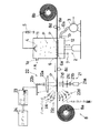
図1は本発明の実施の形態の全体構成図で、機械的並びに光学的構成を表す模式図と電気的構成を表すブロック図とを併記して示す図である。
【0016】
捕集容器1は、本体部11と底部12とからなり、本体部11に大気の流入口1aが形成されている。また、底部12は開閉機構2によって上下動するように構成されており、この底部12の上昇時には図1に示すように、本体部11と底部12とが後述する柔軟なフィルム状の集塵電極6を介在させた状態で密着して気密に接合された状態、つまり捕集容器1が閉じた状態となる。一方、底部12が下降した状態では、本体部11と底部12との間に隙間が形成された状態となり、この状態ではフィルム状の集塵電極6が移動可能となる。
【0017】
底部12には、フレキシブルチューブ12aを介してポンプ3の吸引口に連通する連通口1bが形成されている。従って、底部12を上昇させて捕集容器1を閉じた状態としてポンプ3を駆動することにより、大気が流入口1aを介して捕集容器1内に吸引される。
【0018】
捕集容器1の本体部11の上部には放電電極4が設けられている。この放電電極4には高圧電源5からの高電圧が印加される。また、捕集容器1の本体部11と底部12の間には、柔軟なフィルム状の集塵電極6が配置されている。このフィルム状の集塵電極6は、透明で適当な柔軟性を有する任意の樹脂、例えばポリウレタン等、の表面に透明材料からなる導電性コーティングを施したものであり、底部12に設けられた導電性材料からなる支持部材6aを介して接地電位7に接続される。また、このフィルム状の集塵電極6は、その幅が捕集容器1の同方向寸法よりも若干長く、長さはその寸法よりも十分に長く、これにより、捕集容器1を閉じた状態では本体部11と底部12に挟み込まれることによって、前記したようにこれら両者間の気密を保つとともに、その両端部は巻き取り機構8の巻回軸8a,8bに巻回されている。そして、この巻き取り機構8の駆動により、フィルム状の集塵電極6は図中左方に向けて一定量ずつ所定のインターバルで間欠的に巻き取られていくようになっている。なお、図において8c,8d,8eはガイドロールである。
【0019】
以上の構成において、捕集容器1を閉じた状態でポンプ3を駆動して大気を当該捕集容器1内に吸引するとともに、放電電極4に高圧電源5からの高電圧を印加すると、放電電極4の周囲の空気が電離して単極イオンが発生し、その単極イオンは、集塵電極6との電位差によって集塵電極6側に向けて移動し、その過程で捕集容器1内に吸引された大気中の浮遊粒子状物質Pと接触してこれを帯電させる。帯電した浮遊粒子状物質Pは、同じく放電電極4との電位差によって集塵電極6の上面に捕集されていく。このとき、集塵電極6が接地されているので、比較的多量の浮遊粒子状物質Pを捕集しても集塵電極6の電位が変化することがなく、高い効率のもとに浮遊粒子状物質Pを捕集することができる。
【0020】
そして、以上の捕集動作をあらかじめ設定されている一定時間だけ継続した時点で、ポンプ3を停止し、開閉機構2および巻き取り機構8の駆動により、捕集容器1の底部12を下降させて当該捕集容器1を開き、次いで集塵電極6を巻き取ってそれまで捕集容器1内に位置して浮遊粒子状物質Pが付着している部位が捕集容器1外に引き出されると同時に、未使用の部位が新たに捕集容器1内に引き込まれ、その状態で底部12を上昇させて再び捕集容器1を閉じる。
【0021】
以上の動作を繰り返すことにより、フィルム状の集塵電極6には、その長手方向に一定の間隔で浮遊粒子状物質Pの付着領域が形成されていき、大気中の浮遊粒子状物質Pを連続的に捕集することができる。
【0022】
さて、捕集容器1と巻き取り機構8の巻き取り側の巻回軸8aの間に、レーザ回折・散乱式粒度分布測定装置20が配置されている。レーザ回折・散乱式粒度分布測定装置20は、捕集容器1から引き出されたフィルム状の集塵電極6の浮遊粒子状物質Pの付着部位にレーザ光を照射する照射光学系21と、その照射光学系21からのレーザ光の浮遊粒子状物質Pによる回折・散乱光の空間強度分布を測定する測定光学系22と、その測定光学系22の出力をサンプリングするデータサンプリング回路23、およびそのデータサンプリング回路23によりサンプリングされた回折・散乱光の空間強度分布データを用いて、集塵電極6に付着している浮遊粒子状物質Pの粒度分布を算出するコンピュータ24を主体として構成されている。
【0023】
照射光学系21は、レーザ光源21a,集光レンズ21b、空間フィルタ21cおよびコリメートレンズ21dによって構成され、レーザ光源21aから出力されたレーザ光を平行光束として集塵電極6に照射する。このレーザ光は、集塵電極6に付着している浮遊粒子状物質Pにより回折・散乱を受け、その回折・散乱光の空間強度分布が測定光学系22によって測定される。
【0024】
測定光学系22は、照射光学系21の光軸上に集塵電極6を挟んで配置された集光レンズ22aおよび回折・前方散乱光センサ22bと、集光レンズ22aの横に設けられた前方広角度散乱光センサ群22c、および集塵電極6よりも照射光学系21側に設けられた側方・後方散乱光センサ群22dによって構成されている。回折・前方散乱光センサ22bは、リングディテクタと称されるものであって、互いに異なる半径のリング状または1/2リング状もしくは1/4リング状の受光面を有する光センサを同心上に配置した光センサアレイであって、集光レンズ22aにより集光された前方所定角度以内の回折・散乱光の微小角度ごとの強度分布を検出することができる。従って、これらのセンサ群からなる測定光学系22により、集塵電極6に付着している浮遊粒子状物質Pによる回折・散乱光の空間強度分布が、前方微小角度から後方に至る広い範囲で測定される。
【0025】
以上の測定光学系22による各回折・散乱角度ごとの光強度検出信号は、それぞれのアンプ並びにA−D変換器を有してなるデータサンプリング回路23によって増幅されたうえでデジタル化され、回折・散乱光の空間強度分布データとしてコンピュータ24に取り込まれる。
【0026】
コンピュータ24では、その回折・散乱光の空間強度分布データを用いて、レーザ回折・散乱式の粒度分布測定において公知の、ミーの散乱理論およびフラウンホーファの回折理論に基づく演算により、レーザ光が回折・散乱した原因粒子である浮遊粒子状物質Pの粒度分布を算出する。
【0027】
以上の構成において、ポンプ3のON/OFFと放電電極4に対する高電圧の印加/停止、捕集容器1の開閉およびフィルム状の集塵電極6の巻き取り動作と、レーザ回折・散乱式粒度分布測定装置20の起動/停止を同期させることによって、大気中の浮遊粒子状物質を実質的に無人運転のもとに連続的に捕集してその粒度分布を自動的に測定することができる。
【0028】
【発明の効果】
以上のように、本発明の捕集・測定装置によれば、捕集容器内に大気を吸引し、その大気中に含まれる浮遊粒子状物質を、捕集容器内に設けた放電電極によって帯電させて集塵電極上に捕集し、その集塵電極として、容器を貫通して外部から移動させることのできるフィルム状の透明のものを用い、その集塵電極を所定のタイミングで移動させることにより、捕集容器内の集塵電極を実質的に交換することが可能となり、大気中の浮遊粒子状物質を連続的に捕集することができ、その捕集容器外に移動させた透明のフィルム状集塵電極を試料保持部材として、そこにレーザ回折・散乱式の粒度分布測定装置の測定用レーザ光を照射して、集塵電極に付着している浮遊粒子状物質による回折・散乱光を測定してその粒度分布を求めることにより、大幅な省力化ないしは無人化を達成しながら、大気中の浮遊粒子状物質の粒度分布を連続的に測定することが可能となる。
【図面の簡単な説明】
【図1】 本発明の実施の形態の全体構成図で、機械的並びに光学的構成を表す模式図と電気的構成を表すブロック図とを併記して示す図である。
【符号の説明】
1 捕集容器
1a 流入口
1b 連通口
11 本体部
12 底部
2 開閉機構
3 ポンプ
4 放電電極
5 高圧電源
6 フィルム状の集塵電極
7 接地電位
8 巻き取り機構
20 レーザ回折・散乱式粒度分布測定装置
21 照射光学系
22 測定光学系
23 データサンプリング回路
24 コンピュータ
P 浮遊粒子状物質[0001]
BACKGROUND OF THE INVENTION
The present invention relates to an apparatus for collecting and measuring suspended particulate matter present in the atmosphere.
[0002]
[Prior art]
Of the dust suspended in the atmosphere, those having a particle size of 10 μm or less are called suspended particulate matter (SPM). This suspended particulate matter includes rolled-up soil, etc., but most of them are graphite, unburned fuel, and sulfur compounds emitted by diesel vehicles (35% in the Kanto region are from diesel vehicles). Is said to be more harmful. Particulate matter caused by exhaust gas from this diesel vehicle is particularly referred to as DEP. In addition, those having a smaller particle diameter of 2.5 μm or less are called microparticulate substances (PM2.5), and research and research are actively conducted in the West. In the case of this PM2.5, it is said that the ratio of exhaust gas from diesel vehicles becomes higher.
[0003]
Investigate the shape of suspended particulate matter (SPM) and microparticulate matter (PM2.5) in the atmosphere as described above, measure the particle size distribution, or identify the chemical substances contained therein To do so, it is necessary to collect these particulate matter from the atmosphere.
[0004]
Such a method for collecting suspended particulate matter in the atmosphere is most commonly a method for collecting suspended particulate matter on a filter (see, for example, Patent Document 1). However, it is extremely difficult to extract the particulate matter adhering to the filter alone. Therefore, when observing with a microscope, the particulate matter attached to the filter is observed. In this filter image, the particle image becomes unclear and difficult to observe. In addition, even when the collected suspended particulate matter is subjected to various chemical analyses, it is difficult to extract the suspended particulate matter alone from the filter. In this case, for example, in an X-ray fluorescence spectrometer, it is difficult to irradiate only the particles with X-rays, and there is a problem that the analysis becomes substantially impossible.
[0005]
In view of this, the present inventor, in cooperation with others, sucks the atmosphere into a collection container in which the discharge electrode and the dust collection electrode are housed, and removes the suspended particulate matter sucked into the container from the discharge electrode. There has already been proposed a method of charging with polar ions and attracting and collecting the charged suspended particulate matter to a dust collecting electrode to which a potential difference is given to the discharge electrode (for example, Japanese Patent Application Nos. 2001-216198 and 2001). Japanese Patent Application No. 2002-12322).
[0006]
The suspended particulate matter electrically collected on such a dust collection electrode can be easily extracted as a single substance, easily observed under a microscope, and easily sampled into various chemical analysis instruments. It becomes. Furthermore, there is an advantage that the particle size distribution can be easily measured by a laser diffraction / scattering type particle size distribution measuring apparatus.
[0007]
[Patent Document 1]
Japanese Patent Laid-Open No. 2001-50870 (Page 5-8, FIGS. 1-3)
[0008]
[Problems to be solved by the invention]
By the way, according to the above proposal by the present inventors, when an appropriate amount of suspended particulate matter is collected in one dust collecting electrode, the dust collecting electrode is taken out and used for various measurements. When observing suspended particulate matter over time, it is necessary to take out the previous dust collection electrode and place a new dust collection electrode before use in the container. This is a tedious task for continuous observation of substances.
[0009]
The present invention has been made in view of such circumstances, and continuously collects suspended particulate matter in the atmosphere under great labor-saving or unmanned conditions, and sequentially measures the particle size distribution. It is an object of the present invention to provide can Ru equipment of things.
[0010]
[Means for Solving the Problems]
Collecting and measuring system of suspended particulate matter in the air of the present invention is an apparatus for measuring and collecting suspended particulate matter in the atmosphere, and collection vessel, in the collection vessel A pump that sucks air, a discharge electrode that is placed in a collection container and generates monopolar ions to charge suspended particulate matter in the container, and a trap is obtained by applying a potential difference to the discharge electrode. A collecting device comprising a dust collecting electrode that attracts and collects suspended particulate matter charged in the collecting container, and suspended particles that are arranged adjacent to the collecting device and collected by the collecting device A dust collecting electrode of the collecting device is a transparent and flexible film-like member provided with a conductive coating, and penetrates the collecting container. Arranged movably from the outside, the measuring device has its collection The dust collection electrode drawn out of the collection container is irradiated with laser light using the sample holding member as a sample holding member, and the spatial intensity distribution of diffracted / scattered light due to suspended particulate matter adhering to it is measured and its floating It is characterized by being a laser diffraction / scattering type particle size distribution measuring device for calculating the particle size distribution of particulate matter.
[0011]
Drawer Here, in the absorption-measuring device for suspended particulate matter in the air of the present invention, by winding the fill beam-shaped dust collecting electrodes, a portion was collected suspended particulate matter out of the container In addition, it is possible to suitably employ a configuration (claim 2) including a winding mechanism that draws an uncollected portion into the container.
[0012]
The present invention basically employs a structure in which suspended particulate matter is charged by a discharge electrode arranged in a collection vessel and electrically attracted to a dust collection electrode, as in the previous proposal, The dust collecting electrode is transparent and flexible, and the film dust collecting electrode is disposed so as to be movable from the outside through the collection container to collect suspended particulate matter. By irradiating a transparent film-like dust collecting electrode moved outside the collection container with laser light for measurement by a laser diffraction / scattering particle size distribution measuring device, the intended purpose is achieved. is there.
[0013]
That is, in the collection / measurement apparatus of the present invention, when the atmosphere is sucked into the collection container by a pump and the unipolar ions are generated by the discharge electrode arranged in the collection container, the unipolar ions Moves toward the dust collection electrode, which has a potential difference with respect to the discharge electrode, and in the process, contacts the suspended particulate matter contained in the air sucked into the collection container and charges it. . The charged suspended particulate matter moves to a dust collecting electrode that is similarly given a potential difference with respect to the discharge electrode, and is collected on the dust collecting electrode with high efficiency. If this dust collection electrode is transparent and flexible, and is movable from the outside through the collection container, after collecting an appropriate amount of suspended particulate matter, By moving the dust collection electrode, it is possible to easily pull out the part where suspended particulate matter was collected to the outside and draw the part that has not been collected into the collection container. Can be easily replaced. A laser diffraction / scattering particle size distribution measuring device is arranged adjacent to such a collecting device, and a transparent dust collecting electrode that collects suspended particulate matter and moves it outside the collecting container is used as a sample. Use as a holding member as it is, irradiate laser light for measurement from a laser diffraction / scattering particle size distribution measuring device, and measure the spatial intensity distribution of diffracted / scattered light by suspended particulate matter adhering to a transparent collection electrode. By measuring and measuring the particle size distribution of the suspended particulate matter, it is possible to continuously measure the transition of the particle size distribution of the suspended particulate matter over a long period of time with extremely simple work.
[0014]
In addition, as in the invention according to
[0015]
DETAILED DESCRIPTION OF THE INVENTION
Hereinafter, embodiments of the present invention will be described with reference to the drawings.
FIG. 1 is an overall configuration diagram of an embodiment of the present invention, and is a diagram illustrating a schematic diagram showing a mechanical and optical configuration and a block diagram showing an electrical configuration.
[0016]
The collection container 1 includes a main body portion 11 and a
[0017]
The
[0018]
A
[0019]
In the above configuration, when the
[0020]
Then, when the above collection operation is continued for a predetermined time set in advance, the
[0021]
By repeating the above operation, the adhering regions of the suspended particulate matter P are formed on the film-like
[0022]
A laser diffraction / scattering particle size distribution measuring device 20 is disposed between the collection container 1 and the winding
[0023]
The irradiation
[0024]
The measurement
[0025]
The light intensity detection signal for each diffraction / scattering angle by the measurement
[0026]
The
[0027]
In the above configuration, ON / OFF of the
[0028]
【The invention's effect】
As described above, according to the collection and measurement apparatus of the present invention, the atmosphere is sucked into the collection container, and the suspended particulate matter contained in the atmosphere is charged by the discharge electrode provided in the collection container. by collected on the dust collecting electrode, as a dust collecting electrode, used as the film-like transparent which can be moved from the outside through the container, moving the dust collecting electrode at a predetermined timing Makes it possible to substantially replace the dust collection electrode in the collection container, continuously collect suspended particulate matter in the atmosphere, and move the transparent electrode moved out of the collection container. Diffraction / scattered light caused by suspended particulate matter adhering to the dust collection electrode by irradiating the film-shaped dust collection electrode as a sample holding member and irradiating it with laser light for measurement by a laser diffraction / scattering particle size distribution measuring device By measuring the particle size distribution While achieving significant labor saving or unmanned, it is possible to continuously measure the particle size distribution of suspended particulate matter in the air.
[Brief description of the drawings]
FIG. 1 is an overall configuration diagram of an embodiment of the present invention, and is a diagram illustrating a schematic diagram showing a mechanical and optical configuration and a block diagram showing an electrical configuration.
[Explanation of symbols]
DESCRIPTION OF SYMBOLS 1 Collection container
Claims (2)
上記捕集装置の集塵電極は透明で、かつ、柔軟なフィルム状部材に導電性コーティングを施したものであって、上記捕集容器を貫通して外部から移動自在に配置され、上記測定装置は、その捕集装置の捕集容器外に引き出された上記集塵電極を試料保持部材としてレーザ光を照射し、そこに付着している浮遊粒子状物質による回折・散乱光の空間強度分布を測定してその浮遊粒子状物質の粒度分布を算出するレーザ回折・散乱式粒度分布測定装置であることを特徴とする浮遊粒子状物質の捕集・測定装置。An apparatus for collecting and measuring suspended particulate matter contained in the atmosphere, comprising a collection container, a pump for sucking air into the collection container, and a monopolar ion disposed in the collection container A discharge electrode that charges the suspended particulate matter in the container and the dust collection that attracts and collects the suspended particulate matter charged in the collection container by applying a potential difference to the discharge electrode A collecting device comprising an electrode, and a measuring device arranged adjacent to the collecting device and measuring the suspended particulate matter collected by the collecting device,
The dust collecting electrode of the collecting device is a transparent and flexible film-like member provided with a conductive coating, and is disposed so as to be movable from the outside through the collecting container. Irradiates laser light using the dust collection electrode drawn out of the collection container of the collection device as a sample holding member, and the spatial intensity distribution of the diffracted / scattered light due to suspended particulate matter adhering thereto. An apparatus for collecting and measuring suspended particulate matter, which is a laser diffraction / scattering particle size distribution measuring device that measures and calculates the particle size distribution of the suspended particulate matter.
Priority Applications (1)
| Application Number | Priority Date | Filing Date | Title |
|---|---|---|---|
| JP2002346197A JP4058624B2 (en) | 2002-11-28 | 2002-11-28 | Device for collecting and measuring suspended particulate matter in the atmosphere |
Applications Claiming Priority (1)
| Application Number | Priority Date | Filing Date | Title |
|---|---|---|---|
| JP2002346197A JP4058624B2 (en) | 2002-11-28 | 2002-11-28 | Device for collecting and measuring suspended particulate matter in the atmosphere |
Publications (2)
| Publication Number | Publication Date |
|---|---|
| JP2004177347A JP2004177347A (en) | 2004-06-24 |
| JP4058624B2 true JP4058624B2 (en) | 2008-03-12 |
Family
ID=32707176
Family Applications (1)
| Application Number | Title | Priority Date | Filing Date |
|---|---|---|---|
| JP2002346197A Expired - Fee Related JP4058624B2 (en) | 2002-11-28 | 2002-11-28 | Device for collecting and measuring suspended particulate matter in the atmosphere |
Country Status (1)
| Country | Link |
|---|---|
| JP (1) | JP4058624B2 (en) |
Families Citing this family (2)
| Publication number | Priority date | Publication date | Assignee | Title |
|---|---|---|---|---|
| EP2257789B1 (en) * | 2008-02-26 | 2020-10-28 | Battelle Memorial Institute | Biological and chemical microscopic targeting |
| US9618431B2 (en) * | 2010-11-30 | 2017-04-11 | Inspirotec, Inc. | Electrokinetic device for capturing assayable agents in a dielectric fluid |
Family Cites Families (22)
| Publication number | Priority date | Publication date | Assignee | Title |
|---|---|---|---|---|
| JPS6054748A (en) * | 1983-09-05 | 1985-03-29 | Dengen Autom Kk | Device for detecting dust collecting limit of dust collecting electrode |
| JPS6146444U (en) * | 1984-08-29 | 1986-03-28 | 工業技術院長 | dust sampler |
| GB8722982D0 (en) * | 1987-09-30 | 1987-11-04 | Rood A P | Measurement of airborne fibres |
| JP2504827Y2 (en) * | 1988-11-22 | 1996-07-24 | 工業技術院長 | Particle analyzer for analysis |
| JPH0312246A (en) * | 1989-06-12 | 1991-01-21 | Matsushita Refrig Co Ltd | Air purifying device |
| JP3403226B2 (en) * | 1993-09-20 | 2003-05-06 | リコーエレメックス株式会社 | Electric dust collector |
| JP3446410B2 (en) * | 1995-07-24 | 2003-09-16 | 株式会社島津製作所 | Laser diffraction particle size distribution analyzer |
| JPH10288670A (en) * | 1997-04-15 | 1998-10-27 | Toshiba Corp | Non-contact surface contamination inspection method and surface treatment method and device |
| JP3108649B2 (en) * | 1997-04-18 | 2000-11-13 | 株式会社ヤマダコーポレーション | Vehicle exhaust gas purification device |
| JP2000074796A (en) * | 1998-08-31 | 2000-03-14 | Shimadzu Corp | Floating particle-like substance measuring apparatus |
| JP2001050870A (en) * | 1999-08-13 | 2001-02-23 | Terumu:Kk | Device for collecting matter in air |
| JP2001104754A (en) * | 1999-10-01 | 2001-04-17 | Shimadzu Corp | Air cleaning apparatus |
| JP2001311776A (en) * | 2000-04-27 | 2001-11-09 | Toshiba Corp | Dust radiation monitor |
| JP3574045B2 (en) * | 2000-05-31 | 2004-10-06 | 紀本電子工業株式会社 | Continuous measurement system for suspended particulate matter |
| JP2002147218A (en) * | 2000-11-08 | 2002-05-22 | Matsumoto Giken Kk | Device of removing particulate material in exhaust gas of diesel engine |
| JP2002156321A (en) * | 2000-11-22 | 2002-05-31 | Shimadzu Corp | Measuring device for suspended particulate matter |
| JP3622696B2 (en) * | 2001-07-17 | 2005-02-23 | 株式会社島津製作所 | Method and apparatus for measuring suspended particulate matter |
| JP3758577B2 (en) * | 2002-01-22 | 2006-03-22 | 株式会社島津製作所 | Device for collecting suspended particulate matter in the atmosphere and measuring method for collected suspended particulate matter |
| JP3786049B2 (en) * | 2002-05-08 | 2006-06-14 | 株式会社島津製作所 | Airborne particulate matter collection device |
| JP2004053357A (en) * | 2002-07-18 | 2004-02-19 | Shimadzu Corp | Collecting method and measuring method of yellow sand particle |
| JP2003315244A (en) * | 2002-04-24 | 2003-11-06 | Shimadzu Corp | Method for measuring granular substances floating in the air |
| JP2003337087A (en) * | 2002-05-20 | 2003-11-28 | Shimadzu Corp | Apparatus for collecting suspended particle |
-
2002
- 2002-11-28 JP JP2002346197A patent/JP4058624B2/en not_active Expired - Fee Related
Also Published As
| Publication number | Publication date |
|---|---|
| JP2004177347A (en) | 2004-06-24 |
Similar Documents
| Publication | Publication Date | Title |
|---|---|---|
| JP3622696B2 (en) | Method and apparatus for measuring suspended particulate matter | |
| US6807874B2 (en) | Collecting apparatus of floating dusts in atmosphere | |
| JP6168208B2 (en) | Sample preparation apparatus with uniform particle concentration distribution, and nanoparticle film deposition apparatus | |
| US8167986B2 (en) | Airborne particulate sampler | |
| US6881246B2 (en) | Collecting device for suspended particles | |
| JP2011506911A (en) | Detection system for airborne particles | |
| US20110246089A1 (en) | Micro-fabricated double condenser method and apparatus for the measurement of number-size distribution of airborne nano-particles | |
| JP2003315244A (en) | Method for measuring granular substances floating in the air | |
| JP3758577B2 (en) | Device for collecting suspended particulate matter in the atmosphere and measuring method for collected suspended particulate matter | |
| JP2004053357A (en) | Collecting method and measuring method of yellow sand particle | |
| JP4058624B2 (en) | Device for collecting and measuring suspended particulate matter in the atmosphere | |
| JP4019267B2 (en) | Device for collecting suspended particulate matter in the atmosphere | |
| JP3758603B2 (en) | Device for collecting suspended particulate matter in the atmosphere | |
| JP2006112929A (en) | Analyzer of floating particles | |
| JP3786049B2 (en) | Airborne particulate matter collection device | |
| JP2003254888A (en) | Method for measuring suspended particulate matter | |
| JP4200373B2 (en) | Airborne particulate matter collection device | |
| JP3961244B2 (en) | Method and apparatus for measuring suspended particulate matter | |
| JP2002116134A (en) | Measuring apparatus for suspended particulate matter | |
| JP3758602B2 (en) | Measuring device for pollen in the atmosphere | |
| US5442190A (en) | Method and apparatus for the measurement of airborne fibres | |
| JP2003215021A (en) | Method for measuring suspended particulate matter in atmosphere | |
| Vuorinen | Charge carrying agglomerates in an electrostatic soot sensor | |
| JP2004340897A (en) | Mass density measuring method of airborne particle in atmospheric air |
Legal Events
| Date | Code | Title | Description |
|---|---|---|---|
| A621 | Written request for application examination |
Free format text: JAPANESE INTERMEDIATE CODE: A621 Effective date: 20050324 |
|
| A977 | Report on retrieval |
Free format text: JAPANESE INTERMEDIATE CODE: A971007 Effective date: 20070502 |
|
| A131 | Notification of reasons for refusal |
Free format text: JAPANESE INTERMEDIATE CODE: A131 Effective date: 20070523 |
|
| A521 | Request for written amendment filed |
Free format text: JAPANESE INTERMEDIATE CODE: A523 Effective date: 20070723 |
|
| A131 | Notification of reasons for refusal |
Free format text: JAPANESE INTERMEDIATE CODE: A131 Effective date: 20070829 |
|
| A521 | Request for written amendment filed |
Free format text: JAPANESE INTERMEDIATE CODE: A523 Effective date: 20071029 |
|
| TRDD | Decision of grant or rejection written | ||
| A01 | Written decision to grant a patent or to grant a registration (utility model) |
Free format text: JAPANESE INTERMEDIATE CODE: A01 Effective date: 20071121 |
|
| A61 | First payment of annual fees (during grant procedure) |
Free format text: JAPANESE INTERMEDIATE CODE: A61 Effective date: 20071204 |
|
| FPAY | Renewal fee payment (event date is renewal date of database) |
Free format text: PAYMENT UNTIL: 20101228 Year of fee payment: 3 |
|
| R150 | Certificate of patent or registration of utility model |
Ref document number: 4058624 Country of ref document: JP Free format text: JAPANESE INTERMEDIATE CODE: R150 Free format text: JAPANESE INTERMEDIATE CODE: R150 |
|
| FPAY | Renewal fee payment (event date is renewal date of database) |
Free format text: PAYMENT UNTIL: 20111228 Year of fee payment: 4 |
|
| FPAY | Renewal fee payment (event date is renewal date of database) |
Free format text: PAYMENT UNTIL: 20121228 Year of fee payment: 5 |
|
| FPAY | Renewal fee payment (event date is renewal date of database) |
Free format text: PAYMENT UNTIL: 20121228 Year of fee payment: 5 |
|
| FPAY | Renewal fee payment (event date is renewal date of database) |
Free format text: PAYMENT UNTIL: 20131228 Year of fee payment: 6 |
|
| LAPS | Cancellation because of no payment of annual fees |