JP4049899B2 - Game machine - Google Patents
Game machine Download PDFInfo
- Publication number
- JP4049899B2 JP4049899B2 JP21648598A JP21648598A JP4049899B2 JP 4049899 B2 JP4049899 B2 JP 4049899B2 JP 21648598 A JP21648598 A JP 21648598A JP 21648598 A JP21648598 A JP 21648598A JP 4049899 B2 JP4049899 B2 JP 4049899B2
- Authority
- JP
- Japan
- Prior art keywords
- ball
- prize ball
- prize
- winning
- payout
- Prior art date
- Legal status (The legal status is an assumption and is not a legal conclusion. Google has not performed a legal analysis and makes no representation as to the accuracy of the status listed.)
- Expired - Lifetime
Links
Images


Description
【0001】
【発明の属する技術分野】
本発明は、遊技者の操作に応じて遊技が行われるパチンコ遊技機やコイン遊技機等の遊技機に関し、特に、遊技盤における遊技領域において遊技者の操作に応じて遊技が行われる遊技機に関する。
【0002】
【従来の技術】
遊技機として、遊技領域に設けられた入賞領域に入賞した遊技球を処理する入賞球処理装置が設けられ、入賞球処理装置によって処理された入賞球1個につきあらかじめ定められた個数の景品玉を遊技者に払い出すものがある。入賞球処理装置には、入賞球を保持する入賞球保持手段と、入賞球保持手段によって保持されている入賞球を検出する入賞球検出手段とが設けられている。そして、このような遊技機は、遊技状態を制御する遊技制御手段と景品玉を払い出す賞球払出手段とを有している。
【0003】
入賞球検出手段からの検出信号は賞球払出手段に入力される。賞球払出手段は、入賞球検出手段から検出信号を受信すると、入賞球が検出されたことを示す入賞球検出信号を遊技制御手段に送出する。すると、遊技制御手段は、その入賞に対する景品玉の個数を示す賞球個数信号を賞球払出手段に返送する。賞球払出手段は、賞球個数信号で指定された個数だけ景品玉が払い出されるように玉払出装置を駆動する。
【0004】
このような遊技機では、遊技者は、遊技者に貸し出された遊技球と遊技者が獲得した景品玉の双方を用いて遊技を行うことができる。よって、一般に、玉払出装置は、賞球用払出装置と玉貸し用払出装置とに兼用されている。すなわち、遊技制御手段から所定個の景品玉の払出を指示されたときには、賞球払出手段は、指示された個数分だけ玉払出装置を駆動する。また、プリペイドカードユニット等から玉貸し要求信号を受けると、所定個の遊技球が払い出されるように玉払出装置を駆動する。
【0005】
また、各入賞に対する賞球数および貸し出される遊技球数はあらかじめ定められた値でなければならないので、玉払出装置には払い出された遊技球数を検出するためのセンサ手段が設けられている。そして、賞球用払出装置は、センサ手段を用いて、あらかじめ定められた所定個数に一致した個数の遊技球が払い出されるように監視している。
【0006】
【発明が解決しようとする課題】
賞球の払出数不足を検出すると、玉払出装置を再度駆動させて不足している賞球を払い出す処理を実行する遊技機がある。しかし、不足分を払い出す際に何等の工夫も施さないと、確実に不足分を払い出すことはできない。
【0007】
そこで、本発明は、賞球の払出数不足を検出でき、かつ、払出数不足が検出されると確実に不足分を払い出すことができる遊技機を提供することを目的とする。
【0008】
【課題を解決するための手段】
本発明による遊技機は、遊技盤に遊技領域が設けられ、遊技領域に設けられている入賞領域への入賞に応じて所定個の賞球が払い出される遊技機であって、遊技の進行を制御し、入賞に応じて払い出すべき賞球の数を示す賞球個数信号を出力する遊技制御手段と、賞球の払い出しを行う賞球払出装置と、賞球個数信号にもとづき賞球個数信号が示す払出予定数分の駆動を賞球払出装置にさせる賞球払出処理を実行する賞球制御手段と、賞球払出装置によって払い出された賞球の数を確認する賞球確認手段とを備え、賞球制御手段は、賞球払出処理を終えた後、賞球確認手段が払出予定数に対する払出数の不足を検知すると、賞球払出装置を再度駆動させて不足している賞球を払い出す処理を実行し、不足している賞球を払い出す場合には、タイムアウトするまでの時間が正常に払出が行われている場合の払出周期よりも長く設定されているタイマを賞球払出装置の駆動が停止した時に起動させ、タイマがタイムアウトしたときに賞球払出装置を再度駆動する処理を実行することにより1個の払い出しに要する時間を通常の払出のときよりも長くすることを特徴とする。
【0010】
賞球確認手段は遊技制御手段に設けられ、賞球確認手段は、払出数の不足を検知した場合には賞球個数信号を継続して出力し続けることによって払出数の不足を賞球制御手段に通知するように構成されていてもよい。
【0012】
【発明の実施の形態】
以下、本発明の一実施形態を図面を参照して説明する。
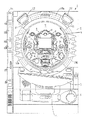
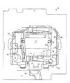
まず、遊技機の一例であるパチンコ遊技機の全体の構成について説明する。図1はパチンコ遊技機1を正面からみた正面図、図2はパチンコ遊技機1の内部構造を示す全体背面図、図3はパチンコ遊技機1の遊技盤を背面からみた背面図である。なお、ここでは、遊技機の一例としてパチンコ遊技機を示すが、本発明はパチンコ遊技機に限られず、例えばコイン遊技機等であってもよい。
【0013】
図1に示すように、パチンコ遊技機1は、額縁状に形成されたガラス扉枠2を有する。ガラス扉枠2の下部表面には打球供給皿3がある。打球供給皿3の下部には、打球供給皿3からあふれた景品玉を貯留する余剰玉受皿4と打球を発射する打球操作ハンドル(操作ノブ)5が設けられている。ガラス扉枠2の後方には、遊技盤6が着脱可能に取り付けられている。また、遊技盤6の前面には遊技領域7が設けられている。
【0014】
遊技領域7の中央付近には、複数種類の図柄を可変表示するための可変表示部9と7セグメントLEDによる可変表示器10とを含む表示装置8が設けられている。この実施の形態では、可変表示部9には、「左」、「中」、「右」の3つの図柄表示エリアがある。表示装置8の側部には、打球を導く通過ゲート11が設けられている。通過ゲート11を通過した打球は、玉出口13を経て始動入賞口14の方に導かれる。通過ゲート11と玉出口13との間の通路には、通過ゲート11を通過した打球を検出するゲートスイッチ12がある。また、始動入賞口14に入った入賞球は、遊技盤6の背面に導かれ、始動口スイッチ17によって検出される。また、始動入賞口14の下部には開閉動作を行う可変入賞球装置15が設けられている。可変入賞球装置15は、ソレノイド16によって開状態とされる。
【0015】
可変入賞球装置15の下部には、特定遊技状態(大当り状態)においてソレノイド21によって開状態とされる開閉板20が設けられている。この実施の形態では、開閉板20が大入賞口を開閉する手段となる。開閉板20から遊技盤6の背面に導かれた入賞球のうち一方(Vゾーン)に入った入賞球はVカウントスイッチ22で検出される。また、開閉板20からの入賞球はカウントスイッチ23で検出される。表示装置8の下部には、始動入賞口14に入った入賞球数を表示する4個の表示部を有する始動入賞記憶表示器18が設けられている。この例では、4個を上限として、始動入賞がある毎に、始動入賞記憶表示器18は点灯している表示部を1つずつ増やす。そして、可変表示部9の可変表示が開始される毎に、点灯している表示部を1つ減らす。
【0016】
遊技盤6には、複数の入賞口19,24が設けられている。遊技領域7の左右周辺には、遊技中に点滅表示される装飾ランプ25が設けられ、下部には、入賞しなかった打球を吸収するアウト口26がある。また、遊技領域7の外側の左右上部には、効果音を発する2つのスピーカ27が設けられている。遊技領域7の外周には、遊技効果LED28aおよび遊技効果ランプ28b,28cが設けられている。そして、この例では、一方のスピーカ27の近傍に、景品玉払出時に点灯する賞球ランプ51が設けられ、他方のスピーカ27の近傍に、補給玉が切れたときに点灯する玉切れランプ52が設けられている。さらに、図1には、パチンコ遊技台1に隣接して設置され、プリペイドカードが挿入されることによって玉貸しを可能にするカードユニット50も示されている。
【0017】
カードユニット50には、使用可能状態であるか否かを示す使用可表示ランプ151、カード内に記録された残額情報に端数(100円未満の数)が存在する場合にその端数を打球供給皿3の近傍に設けられる度数表示LEDに表示させるための端数表示スイッチ152、カードユニット50がいずれの側のパチンコ遊技機1に対応しているのかを示す連結台方向表示器153、カードユニット50内にカードが投入されていることを示すカード投入表示ランプ154、記録媒体としてのカードが挿入されるカード挿入口155、およびカード挿入口155の裏面に設けられているカードリーダライタの機構を点検する場合にカードユニット50を解放するためのカードユニット錠156が設けられている。
【0018】
打球発射装置から発射された打球は、打球レールを通って遊技領域7に入り、その後、遊技領域7を下りてくる。打球が通過ゲート11を通ってゲートスイッチ12で検出されると、可変表示器10の表示数字が連続的に変化する状態になる。また、打球が始動入賞口14に入り始動口スイッチ17で検出されると、図柄の変動を開始できる状態であれば、可変表示部9内の図柄が回転を始める。図柄の変動を開始できる状態でなければ、始動入賞記憶を1増やす。なお、始動入賞記憶については、後で詳しく説明する。可変表示部9内の画像の回転は、一定時間が経過したときに停止する。
【0019】
停止時の画像の組み合わせが大当り図柄の組み合わせであると、大当り遊技状態に移行する。すなわち、開閉板20が、一定時間経過するまで、または、所定個数(例えば10個)の打球が入賞するまで開放する。そして、開閉板20の開放中に打球が特定入賞領域に入賞しVカウントスイッチ22で検出されると、継続権が発生し開閉板20の開放が再度行われる。この継続権の発生は、所定回数(例えば16ラウンド)許容される。
【0020】
停止時の可変表示部9内の画像の組み合わせが確率変動を伴う大当り図柄の組み合わせである場合には、次に大当りとなる確率が高くなる。すなわち、高確率状態という遊技者にとってさらに有利な状態となる。
また、可変表示器10における停止図柄が所定の図柄(当り図柄)である場合に、可変入賞球装置15が所定時間だけ開状態になる。さらに、高確率状態では、可変表示器10における停止図柄が当り図柄になる確率が高められるとともに、可変入賞球装置15の開放時間と開放回数が高められる。
【0021】
次に、パチンコ遊技機1の裏面の構造について図2を参照して説明する。
パチンコ遊技機1の裏面では、図2に示すように、機構板36の上部に玉タンク38が設けられ、パチンコ遊技機1が遊技機設置島に設置された状態でその上方から景品玉が玉タンク38に供給される。玉タンク38内の景品玉は、誘導樋39を通って玉払出装置97に至る。また、機構板36の上部には、パチンコ遊技機1内の各情報を外部に出力するための端子や電源コネクタおよび電源スイッチ等が設けられているターミナル基板160が設置されている。なお、ターミナル基板160の裏面には、各種基板で使用される電圧を生成する電源回路が搭載された電源基板が設置されている。
【0022】
玉タンク38は、その左右に設けられている取付片によって上部ベースユニット161の所定の位置(この位置には、玉タンク38の側面形状に沿った凹部が形成されている)にビスで取り付けられている。また、玉タンク38は、上面が開放したボックス状に形成され、その底面下流側に誘導樋39につながる落下口168が形成されている。落下口168の上部の傾斜底面には揺動自在に軸支されている玉切れ検出レバー166が設けられている。
【0023】
そして、玉切れ検出レバー166の下方には玉切れ検出スイッチ167が設置されている。玉切れ検出スイッチ167が玉タンク38内の補給玉が不足を検出すると、遊技場に設置されているホールコンピュータに補給玉要求信号が出力されるとともに、遊技盤6に設けられている玉切れランプ52が点灯される。玉切れ検出レバー166は、玉タンク38内に補給玉が存在している場合には玉切れ検出スイッチ167をオフ状態にし、玉タンク38内の補給玉がなくなった場合には玉切れ検出スイッチ167をオン状態にする。
【0024】
玉タンク38の下流側に配置された誘導樋39は、上部ベースユニット161の一端から他端に向けて傾斜して取り付けられている。誘導樋39の内部中央には仕切り壁39aが設置され、仕切り壁39aは、落下口168から流出した補給玉を下流に向かって確実に左右2列に整列させるために徐々に高く設置されている。誘導樋39の下流側上部には玉ならし部材170が設置され、玉ならし部材170は、誘導樋39を上下2段になって流れる補給玉を1段にするように作用する。玉ならし部材170の下流側には、玉止め金具171と玉ならし金具172とが設置されている。玉止め金具171は、誘導樋39に貯留された補給玉を故障時や点検時に一時的に止めておくためのものである。また、玉ならし金具172は、補給玉を最終的に1段に整列させるためのものである。
【0025】
誘導樋39のさらに下流側には、逆「く」字状の通路が形成されるカーブ樋174が接続されている。カーブ樋174は、誘導樋39によって前後方向2列になって流下する補給玉を、左右方向3列になって玉払出装置97に向かって落下するように方向転換する。また、カーブ樋174の屈曲部には玉抜き口が形成され、玉抜き口は玉抜き弁175で塞がれている。玉抜き弁175はパチンコ遊技機1の前面から玉抜きピンが差し込まれることによって開放状態とされる。そして、玉抜き弁175の下部には、玉抜き通路176が形成されている。
【0026】
カーブ樋174の左右下部には連結突部177が設けられている。連結突部177には、中間ベースユニット162の上端に形成されている連結凹突部182が挿入される。その状態で、連結凹突部182の上方からビス止めがなされ、中間ベースユニット162は上部ベースユニット161に固定される。中間ベースユニット162には、カーブ樋174を通った補給玉が通過する通路体や玉払出装置97が固定されるのであるが、中間ベースユニット162および玉払出装置97の構成については後で詳しく説明する。
【0027】
また、機構板36の下部には、下部ベースユニット163が設置されている。下部ベースユニット163の前面側(遊技盤6の側)のほぼ中程には入賞球集合樋203が傾斜して設けられている。入賞球集合樋203は、遊技盤の各入賞装置に入賞した入賞球を受け止めて、後述する入賞球処理装置115に誘導する。よって、入賞球集合樋203の下流側が、入賞球を1個ずつ流下させる入賞球誘導通路205となっている。また、遊技盤6のアウト口26からのアウト玉を導くアウト玉誘導通路206も形成されている。アウト玉誘導通路206の末端は、玉抜き下部通路207に合流するように形成されている。
【0028】
下部ベースユニット163の後面側(遊技盤6から遠い側)には、景品玉払出通路208が形成されている。そして、景品玉払出通路208の下端には上皿連通口210が形成されている。上皿連通口210は、遊技機の前面に設置されている打球供給皿3に景品玉を導くものである。また、景品玉払出通路208の側方には、玉抜き通路176と連通する玉抜き下部通路207が形成されている。玉抜き下部通路207は、途中で景品玉払出通路208と入賞球出口221と連通し、最終的にアウト玉誘導通路206と合流する。
【0029】
下部ベースユニット163の下部には、賞球制御回路基板収納部148に取り付けられた基板ボックス149が設置されている。基板ボックス149には、賞球制御基板37が収納されている。そして、賞球制御基板37には、玉払出装置97や入賞球処理装置115およびカードユニット50からの配線を接続するためのコネクタ153が設置されている。そして、下部ベースユニット163の下部右側には、入賞球を保持するとともに、保持されている入賞球を検出する入賞球処理装置115が配置されている。
【0030】
図3はパチンコ遊技機1の遊技盤を背面からみた背面図である。遊技盤6の裏面には、図3に示すように、各入賞口および入賞球装置に入賞した入賞玉を所定の入賞経路に沿って導く入賞玉集合カバー40が設けられている。入賞玉集合カバー40に導かれる入賞玉のうち、開閉板20を経て入賞したものは、玉払出装置97が相対的に多い景品玉数(例えば15個)を払い出すように制御される。始動入賞口14を経て入賞したものは、玉払出装置(図3において図示せず)が相対的に少ない景品玉数(例えば6個)を払い出すように制御される。そして、その他の入賞口24および入賞球装置を経て入賞したものは、玉払出装置が相対的に中程度の景品玉数(例えば10個)を払い出すように制御される。なお、図3には、中継基板33が例示されている。
【0031】
賞球払出制御を行うために、入賞球検出スイッチ122、始動口スイッチ17およびカウントスイッチ23からの信号が、主制御基板31に送られる。主制御基板31に入賞球検出スイッチ122のオン信号が送られると、主制御基板31から賞球基板37に賞球個数信号が送られる。入賞があったことは入賞球検出スイッチ122で検出されるが、その場合に、主制御基板31から、賞球基板37に賞球個数信号が与えられる。例えば、始動口スイッチ17のオンに対応して入賞球検出スイッチ122がオンすると、賞球個数信号に「6」が出力され、カウントスイッチ23のオンに対応して入賞球検出スイッチ122がオンすると、賞球個数信号に「15」が出力される。そして、それらのスイッチがオンしない場合に入賞球検出スイッチ122がオンすると、賞球個数信号に「10」が出力される。
【0032】
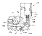
図4および図5は、機構板36の下部ベースユニット163に設置されている入賞球処理装置115の構成を示す断面図である。図4は入賞球が停留している状態を示し、図5は停留されていた入賞球が開放された状態を示す。
入賞球処理装置115は、取付ベース116に集約して形成される。従って、入賞球処理装置115は、容易に機構板36の下部ベースユニット163に取り付けられる。また、取付ベース116の周囲には補強リブ117が形成され、全体の剛性が強化されている。取付ベース116の下部側方から中央にかけて、屈曲する入賞球流下路120が形成されている。そして、入賞球流下路120の屈曲部よりやや下方に入賞球検出スイッチ122が係止爪123によって固定されている。入賞球検出スイッチ122は近接型のスイッチであって、その前方部に入賞球が通過する通過穴が形成されている。
【0033】
また、入賞球検出スイッチ122の通過穴を挟むように第1玉係止部材124と第2玉係止部材130とが、それぞれ支軸125,131を中心にして揺動自在に支えられている。第1玉係止部材124の後端は、リンク杆126を介して排出ソレノイド127のプランジャ128に連結されている。排出ソレノイド127は、取付ベース116から突出している係止爪によって着脱自在に装着される。また、プランジャ128の周囲にはスプリング129が設けられプランジャ128を下方に向けて常に付勢している。
【0034】
第1玉係止部材124の先端側の上部には玉止部124aが形成され、その下部に第2玉係止部材130と係合する係合片124bが形成されている。第2玉係止部材130の前方上部には玉止部130aが形成され、その中ほどに係合片124bに係合する係合凹部130bが形成されている。
【0035】
次に、図4および図5を参照して入賞球処理装置115の動作を説明する。
排出ソレノイド127がオフである通常の状態では、図4に示すように、第1玉係止部124の玉止部124aは入賞球流下路120内せず、第2玉係止部130の玉止部130aが、入賞球流下路120における入賞球検出スイッチ122の下方に突出した状態になっている。そのような状態で入賞球が発生して入賞球が流下路120に流入すると、先頭の入賞球P1は、入賞球検出スイッチ122に形成されている通過穴に入った状態で玉止部130aによって停留される。すると、入賞球検出スイッチ122は、主制御基板31の基本回路53に検出信号を送る。すると、主制御基板31の基本回路53は、賞球基板37に賞球個数信号を出力する。その結果、賞球基板37における賞球制御用マイクロコンピュータの制御によって玉払出装置が97が駆動制御されて所定個数の景品玉の払出が行われる。
【0036】
なお、先頭の入賞球P1が玉止部130aで停留しているときに後続の入賞球が流入すると全ての入賞球の玉圧が玉止部130aにかかるが、その荷重は、玉止部130aのほぼ真下に位置する支軸131で受け止められる。よって、係合凹部130bと係合片124bとの係合による第1玉係止部材124への負荷が減少する。これによって、プランジャ128がスプリング129の付勢力に抗して上昇することがない。すなわち、多数の入賞球の荷重によって第1玉係止部材124および第2玉係止部130が規定外の動きをすることはなく、確実に入賞球は1個ずつ処理される。
【0037】
所定個数の景品玉の払出が終了すると、賞球制御用マイクロコンピュータから入賞球排出ソレノイド127に駆動信号が送られて入賞球排出ソレノイド127を所定時間オンする。入賞球排出ソレノイド127がオンすると、図5に示すように、玉止部124aが入賞球流下路120内に進入する。よって、次の入賞球P2の入賞球検出スイッチ122の通過穴への進入が阻止されるとともに、玉止部130aが入賞球流下路120から退避する。従って、先頭の入賞球P1が開放されて流下する。そして、所定時間が経過して入賞球排出ソレノイド127がオフすると、図4に示された状態に戻り、次の入賞球にもとづく景品玉の払出動作が行われる。
【0038】
なお、この実施形態では、入賞球検出スイッチ122が入賞球を検出してから玉払出装置97を駆動するまでの時間をWAIT時間といい、WAIT時間は、変動制御されるようになっている。
以上のように、入賞球処理装置115は、発生した入賞球を一時停留し、所定数の景品玉が払い出される毎に1個ずつ入賞球を排出処理する。
【0039】
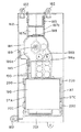
次に、機構板36に設置されている中間ベースユニット162と玉払出装置97の構成について説明する。
図6に示すように、中間ベースユニット162の上下には連結凹突部182が形成されている。連結凹突部182は、中間ベースユニット162と上部ベースユニット161および下部ベースユニット163を連結固定するものであって、上部ベースユニット161の連結突部177に上部の連結凹突部182が連結固定され、下部ベースユニット163の連結突部202に下部の連結凹突部182が連結固定される。
【0040】
中間ベースユニット162の上部には通路体184が固定されている。そして、通路体184の下部に玉払出装置97が固定されている。通路体184は、カーブ樋174によって流下方向を左右方向変換された3列の景品玉を流下させる景品玉通路186a,186b,186cを有する。景品玉通路186a,186b,186cの上流側には、玉切れスイッチ187a,187b,187cが設置されている。玉切れスイッチ187a,187b,187cは、景品玉通路186a,186b,186c内の景品玉の有無を検出するものであって、玉切れスイッチ187a,187bが景品玉を検出しなくなると玉払出装置97における賞球モータ(図6において図示せず)の回転を停止して賞球払出が不動化される。また、玉切れスイッチ187cが景品玉を検出しなくなると玉払出装置97における玉貸しモータ(図6において図示せず)の回転を停止して玉貸しが不動化される。なお、玉切れスイッチ187a,187b,187cは、景品玉通路186a,186b,186cに27〜28個の景品玉が存在することを検出できるような位置に係止片188によって係止されている。
【0041】
通路体184の中央部は、内部を流下する景品玉の玉圧を弱めるように、左右に湾曲する形状に形成されている。そして、景品玉通路186a,186bの間に止め穴189が形成されている。止め穴189の裏面は中間ベースユニット162に設けられている取付ボスがはめ込まれる。その状態で止めねじがねじ止めされて、通路体184は中間ベースユニット162に固定される。なお、ねじ止めされる前に、中間ベースユニット162に設けられている係止突片185によって通路体184の位置合わせを行えるようになっている。
【0042】
通路体184の下方には、玉払出装置97に景品玉を供給するとともに故障時等には玉払出装置97への景品玉の供給を停止する玉止め装置190が設けられている。玉止め装置190の下方に設置される玉払出装置97は、直方体状のケース198の内部に収納されている。ケース198の左右4箇所には突部が設けられている。各突部が中間ベースユニット162に設けられている位置決め突片200に係った状態で、中間ベースユニット162の下部に設けられている弾性係合片201にケース198の下端がはめ込まれる。
【0043】
次に、玉払出装置97の構成および作用を図7〜図11を参照して説明する。図7は、図6に示された玉払出装置97の左側部分である賞球機構部分97Aの分解斜視図、図8は玉払出装置97の賞球機構部分97Aを前方(機構板36に垂直な方向)から見た部分断面図、図9は玉払出装置97の賞球機構部分97Aを側方(機構板36に平行な方向)から見た部分断面図、図10は図6に示された玉払出装置97の右側部分である玉貸し機構部分97Cの分解斜視図、図11は玉払出装置97の玉貸し機構部分97Cを側方から見た部分断面図である。
【0044】
まず、図7〜図9を参照して玉払出装置97の賞球機構部分97Aの構成および作用を説明する。賞球機構部分97Aにおいて、図7〜図9に示すステッピングモータ(賞球モータ)289Aがスクリュー288Aを回転させることによって、賞球にもとづく景品玉を1個ずつ払い出す。
【0045】
図7に示すように、玉払出装置97の賞球機構部分97Aは、2つのケース198a,198bを有する。ケース198aの左右2箇所に、玉払出装置97の設置位置上部に設けられた位置決め突片200(図6参照)に当接される係合突部280a,280bが設けられている。また、それぞれのケース198a,198bには、玉供給路281a,281bが形成されている。玉供給路281a,281bは湾曲面282a,282bを有し、湾曲面282a,282bの終端の下方には、玉送り水平路284a,284bが形成されている。さらに、玉送り水平路284a,284bの終端に玉排出路283a,283bが形成されている。玉供給路281a,281b、玉送り水平路284a,284bおよび玉排出路283a,283bは、ケース198a,198bをそれぞれ前後に区画する区画壁295a,295bの前方に形成されている。
【0046】
また、区画壁295a,295bの前方において、玉圧緩衝部材285Aがケース198a,198b間に挟み込まれる。玉圧緩衝部材285Aは、玉払出装置97の賞球機構部分97Aに供給される景品玉を左右側方に振り分けて玉供給路281a,281bに誘導する。また、玉圧緩衝部材285Aの下部には、発光素子(LED)286Aと受光素子287Aとによる賞球モータ位置センサ300Aが設けられている。発光素子286Aと受光素子287Aとは、所定の間隔をあけて設けられている。そして、この間隔内に、スクリュー288Aの先端が挿入されるようになっている。なお、玉圧緩衝部材285Aは、ケース198a,198bが張り合わされたときに、完全にその内部に収納固定される。
【0047】
玉送り水平路284a,284bには、払出モータ289Aによって回転させられるスクリュー288Aが配置されている。払出モータ289Aはモータ固定板290Aに固定され、モータ固定板290Aは、区画壁295a,295bの後方に形成される固定溝291a,291bにはめ込まれる。その状態で払出モータ289Aのモータ軸が区画壁295a,295bの前方に突出するので、その突出の前方にスクリュー288Aが固定される。スクリュー288Aの外周には、払出モータ289Aの回転によって玉送り水平路284a,284bに載置された景品玉を前方に移動させるための螺旋突起288aが設けられている。
【0048】
そして、スクリュー288Aの先端には、発光素子286Aを収納するように凹部が形成され、その凹部の外周には、2つの切欠部292Aが互いに180度離れて形成されている。従って、スクリュー288Aが1回転する間に、発光素子286Aからの光は、切欠部292Aを介して受光素子287Aで2回検出される。なお、発光素子286A、受光素子287Aおよび払出モータ289Aからの配線293Aは、まとめられてケース198a,198bの後部下方に形成された引出穴から外部に引き出されコネクタ294Aに結線される。
【0049】
景品玉が玉送り水平路284a,284bに載置された状態において、払出モータ289Aが回転すると、スクリュー288Aの螺旋突起288aによって、景品玉は、玉送り水平路284a,284b上を前方に向かって移動する。そして、遂には、玉送り水平路284a,284bの終端から玉排出路283a,283bに落下する。このとき、左右の玉送り水平路284a,284bからの落下は交互に行われる。すなわち、スクリュー288Aが半回転する毎に一方から1個の景品玉が落下する。従って、1回の検出毎に受光素子287Aから出力される信号の数が1個の入賞に対応してあらかじめ定められた景品玉数に到達したときに払出モータ289Aの駆動を停止するように制御すれば、正確に入賞に対応した景品玉数を払い出すことができる。
【0050】
また、玉送り水平路284a,284bの下方には、例えば近接スイッチによる賞球カウントスイッチ301A,301Bが設けられている。玉送り水平路284a,284bから1個の景品玉が落下する毎に、賞球カウントスイッチ301A,301Bがオンする。従って、賞球カウントスイッチ301A,301Bの検出信号によって、実際に払い出された景品玉の数を計数することができる。
【0051】
次に、図10,図11参照して玉払出装置97の玉貸し機構部分97Cの構成および作用を説明する。玉払出装置97の玉貸し機構部分97Cにおいて、図8および図10に示すステッピングモータ(玉貸しモータ)289Cがスクリュー288Cを回転させることによって、貸し玉を1個ずつ払い出す。
【0052】
図10に示すように、玉払出装置97の玉貸し機構部分97Cは、2つのケース198c,198dを有する。198dの左右2箇所に、玉払出装置97の設置位置上部に設けられた位置決め突片200(図6参照)に当接される係合突部280a,280bが設けられている。また、ケース198cには、玉供給路281cが形成されている。玉供給路281cは湾曲面282cを有し、湾曲面282cの終端の下方には、玉送り水平路284cが形成されている。さらに、玉送り水平路284cの終端に玉排出路283cが形成されている。玉供給路281c、玉送り水平路284cおよび玉排出路283cは、ケース198cを前後に区画する区画壁295cの前方に形成されている。
【0053】
また、区画壁295cの前方において、玉圧緩衝部材285Cがケース198c,198d間に挟み込まれる。玉圧緩衝部材285Cは、玉貸し機構部分97Cに供給される貸し玉を玉供給路281cに誘導する。また、玉圧緩衝部材285Cの下部には、発光素子(LED)286Cと受光素子287Cとによる玉貸しモータ位置センサ300Cが設けられている。発光素子286Cと受光素子287Cとは、所定の間隔をあけて設けられている。そして、この間隔内に、スクリュー288Cの先端が挿入されるようになっている。なお、玉圧緩衝部材285Cは、ケース198c,198dが張り合わされたときに、完全にその内部に収納固定される。
【0054】
玉送り水平路284cには、払出モータ289Cによって回転させられるスクリュー288Cが配置されている。払出モータ289Cはモータ固定板290Cに固定され、モータ固定板290Cは、区画壁295cの後方に形成される固定溝291cにはめ込まれる。その状態で払出モータ289Cのモータ軸が区画壁295cの前方に突出するので、その突出の前方にスクリュー288Cが固定される。スクリュー288Cの外周には、払出モータ289Cの回転によって玉送り水平路284cに載置された貸し玉を前方に移動させるための螺旋突起288cが設けられている。
【0055】
そして、スクリュー288Cの先端には、発光素子286Cを収納するように凹部が形成され、その凹部の外周には、2つの切欠部292Cが互いに180度離れて形成されている。従って、スクリュー288Cが1回転する間に、発光素子286Cからの光は、切欠部292Cを介して受光素子287Cで2回検出される。なお、発光素子286C、受光素子287Cおよび払出モータ289Cからの配線293Cは、まとめられてケース198c,198dの後部下方に形成された引出穴から外部に引き出されコネクタ294Cに結線される。
【0056】
貸し玉が玉送り水平路284cに載置された状態において、払出モータ289Cが回転すると、スクリュー288Cの螺旋突起288cによって、貸し玉は、玉送り水平路284c上を前方に向かって移動する。そして、遂には、玉送り水平路284cの終端から玉排出路283cに落下する。このとき、スクリュー288Aが1回転する毎に1個の貸し玉が落下する。従って、この構成では、1個の貸し玉が落下する毎に、発光素子286Cからの光が受光素子287Cによって2回検出されることになる。従って、受光素子287Cから出力される信号の数があらかじめ定められた貸し玉数に到達したときに払出モータ289Cの駆動を停止するように制御すれば、正確な数の貸し玉を払い出すことができる。なお、この構成では、受光素子287Cから2nの検出信号が出力されると、n個の貸し玉が払い出されたことになる。
【0057】
また、玉送り水平路284cの下方には、例えば近接スイッチによる賞球カウントスイッチ301Cが設けられている。玉送り水平路284cから1個の貸し玉が落下する毎に、賞球カウントスイッチ301Cがオンする。従って、賞球カウントスイッチ301Cの検出信号によって、実際に払い出された貸し玉の数を計数することができる。
【0058】
玉払出装置97は、賞球機構部分97Aの2つのケース198a,198bが密着され、玉貸し機構部分97Cの2つのケース198c,198dが密着された後に、ねじ止めされることによって一体化される。従って、賞球機構部分97Aと玉貸し機構部分97Cとが独立した機構部分として設けられているが、玉払出装置97は、全体としてコンパクトに形成することができる。賞球機構部分97Aを玉貸し機構部分97Cから独立した機構とすることによって、賞球用玉払出能力を従来の構成に比べて高いものとすることができる。しかも、図7〜図11に示されたように、玉貸し機構部分97Cにおける補給玉の通過路は1条になっているのに対して、賞球機構部分97Aにおける補給玉の通過路は2条になっている。すなわち、賞球機構部分97Aの払出能力は、玉貸し機構部分97Cの払出能力よりも高く設定されている。
【0059】
図7〜図11に示された構成から明らかなように、賞球機構部分97Aの玉払出方式と玉貸し機構部分97Cの玉払出方式とは同じである。単に、補給玉の通過路の数が異なっているだけである。よって、賞球機構部分97Aと玉貸し機構部分97Cとを異なる設計とする必要がなく、賞球機構部分97Aと玉貸し機構部分97Cとを独立した機構部分としたにも関わらず、玉払出装置97の設計は容易である。また、玉払出方式が同じであることから、賞球機構部分97Aと玉貸し機構部分97Cとを独立した機構部分としたにも関わらず、玉払出装置97の制御も容易である。さらに、玉払出方式が同じであることから、賞球機構部分97Aと玉貸し機構部分97Cとを別方式のものとした場合に比べて、構成が単純化され、その結果、信頼性も高くなる。
【0060】
図12は、中間ベースユニット162と玉払出装置97の他の構成例を示す断面図である。
図12に示すように、中間ベースユニット162の上下には連結凹突部182が形成されている。また、中間ベースユニット162の上部には通路体184が固定され、通路体184の下部に玉払出装置97が固定される。この場合には、図2に示されたカーブ樋174は、補給玉の流下方向を左右方向の2列に変換する。そして、通路体184は、変換された2列の景品玉を流下させる景品玉通路186aと他の景品玉通過路を有する。他の景品玉通過路は、さらに2条の景品玉通過路186b,186cに分流する。景品玉通路186aと他の景品玉通過路の上流側には、玉切れスイッチ187a,187bが設置されている。玉切れスイッチ187a,187bは、景品玉通路186aと他の景品玉通過路内の景品玉の有無を検出する。
【0061】
通路体184の中央部は、内部を流下する景品玉の玉圧を弱めるように、左右に湾曲する形状に形成されている。そして、景品玉通路186a,186bの間に止め穴189が形成されている。止め穴189の裏面は中間ベースユニット162に設けられている取付ボスがはめ込まれる。その状態で止めねじがねじ止めされて、通路体184は中間ベースユニット162に固定される。なお、ねじ止めされる前に、中間ベースユニット162に設けられている係止突片185によって通路体184の位置合わせを行えるようになっている。
【0062】
通路体184の下方には、玉払出装置97に景品玉を供給するとともに故障時等には玉払出装置97への景品玉の供給を停止する玉止め装置190が設けられている。玉止め装置190の下方に設置される玉払出装置97は、直方体状のケース198の内部に収納されている。ケース198の左右4箇所には突部が設けられている。各突部が中間ベースユニット162に設けられている位置決め突片200に係った状態で、中間ベースユニット162の下部に設けられている弾性係合片201にケース198の下端がはめ込まれる。
【0063】
玉払出装置97の構成は、図7〜図11に示された構成と同じでよい。すなわち、図7〜図9に示されたように、賞球機構部分97Aにおいて、景品玉が玉送り水平路284a,284bに載置された状態において、払出モータ289Aが回転すると、スクリュー288Aの螺旋突起288aによって、景品玉は、玉送り水平路284a,284b上を前方に向かって移動する。そして、玉送り水平路284a,284bの終端から玉排出路283a,283bに落下する。左右の玉送り水平路284a,284bからの落下は交互に行われ、スクリュー288Aが半回転する毎に一方から1個の景品玉が落下する。
【0064】
この状態では、払出モータ289Aによって、景品玉通路186a,186bによって景品玉が払い出され、景品玉通路186cによって貸し玉が払い出されるが、景品玉通路186b,186cによって構成される側の通路において、図12に示された「A」の玉の払出が行われても、「B」の玉は流下しない。従って、「C]の玉以降の各玉は、全て景品玉通路186bに流入する。よって、図4に示された構成と同様に、入賞に応じた賞球払出時には、景品玉通路186a,186bの2条を用いて払出が行われる。また、玉貸し時には、1条の景品玉通路186cを用いて払出が行われる。
【0065】
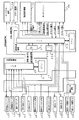
図13は、主制御基板31における回路構成の一例を示すブロック図である。なお、図13には、賞球制御基板37、ランプ制御基板35、音声制御基板70、発射制御基板91および表示制御基板80も示されている。主制御基板31には、プログラムに従ってパチンコ遊技機1を制御する基本回路53と、ゲートスイッチ12、始動口スイッチ17、Vカウントスイッチ22、カウントスイッチ23、入賞球検出スイッチ122および余剰玉受皿4の満タンを検出する満タンスイッチ402からの信号を基本回路53に与えるスイッチ回路58と、可変入賞球装置15を開閉するソレノイド16、開閉板20を開閉するソレノイド21および入賞球排出ソレノイド127を基本回路53からの指令に従って駆動するソレノイド回路59と、始動記憶表示器18の点灯および滅灯を行うとともに7セグメントLEDによる可変表示器10と装飾ランプ25とを駆動するランプ・LED回路60とを含む。
【0066】
また、基本回路53から与えられるデータに従って、大当りの発生を示す大当り情報、可変表示部9の画像表示開始に利用された始動入賞球の個数を示す有効始動情報、確率変動が生じたことを示す確変情報等をホール管理コンピュータ等のホストコンピュータに対して出力する情報出力回路64を含む。
【0067】
基本回路53は、ゲーム制御用のプログラム等を記憶するROM54、ワークメモリとして使用されるRAM55、制御用のプログラムに従って制御動作を行うCPU56およびI/Oポート部57を含む。なお、ROM54,RAM55はCPU56に内蔵されている場合もある。
【0068】
さらに、主制御基板31には、電源投入時に基本回路53をリセットするための初期リセット回路65と、定期的(例えば、2ms毎)に基本回路53にリセットパルスを与えてゲーム制御用のプログラムを先頭から再度実行させるための定期リセット回路66と、基本回路53から与えられるアドレス信号をデコードしてI/Oポート部57のうちのいずれかのI/Oポートを選択するための信号を出力するアドレスデコード回路67とが設けられている。
【0069】
遊技球を打撃して発射する打球発射装置は発射制御基板91上の回路によって制御される駆動モータ94で駆動される。そして、駆動モータ94の駆動力は、操作ノブ5の操作量に従って調整される。すなわち、発射制御基板91上の回路によって、操作ノブ5の操作量に応じた速度で打球が発射されるように制御される。
【0070】
次に遊技機の動作について簡単に説明する。
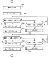
図14は、主制御基板31における基本回路53の動作を示すフローチャートである。上述したように、この処理は、定期リセット回路66が発するリセットパルスによって、例えば2ms毎に起動される。基本回路53が起動されると、基本回路53は、まず、スタックポインタの指定アドレスをセットするためのスタックセット処理を行う(ステップS1)。次いで、初期化処理を行う(ステップS2)。初期化処理では、基本回路53は、RAM55にエラーが含まれているか判定し、エラーが含まれている場合には、RAM55を初期化するなどの処理を行う。そして、表示制御基板80に送出されるコマンドコードをRAM55の所定の領域に設定する処理を行った後に(ステップS3)、コマンドコードを表示制御データとして出力する処理を行う(ステップS4)。
【0071】
次いで、ランプ制御基板35および音声制御基板70に音声発生やLED点灯制御用の所定のコマンドを送信するための処理を行うとともに、情報出力回路64を介して、ホール管理用コンピュータに大当り情報、始動情報、確率変動情報などのデータを送信するための処理を行う(データ出力処理:ステップS5)。また、パチンコ遊技機1の内部に備えられている自己診断機能によって種々の異常診断処理が行われ、その結果に応じて必要ならば警報が発せられる(エラー処理:ステップS6)。
【0072】
次に、遊技制御に用いられる各判定用乱数を示す各カウンタを更新する処理を行う(ステップS7)。ステップS7では、基本回路53は、判定用乱数としての大当り判定用乱数等のカウントアップ(1加算)を行う。
【0073】
次に、基本回路53は、特別図柄プロセス処理を行う(ステップS8)。特別図柄プロセス制御では、遊技状態に応じてパチンコ遊技機1を所定の順序で制御するための特別図柄プロセスフラグに従って該当する処理が選び出されて実行される。そして、特別図柄プロセスフラグの値は、遊技状態に応じて各処理中に更新される。また、普通図柄プロセス処理を行う(ステップS9)。普通図柄プロセス処理では、7セグメントLEDによる可変表示器10を所定の順序で制御するための普通図柄プロセスフラグに従って該当する処理が選び出されて実行される。そして、普通図柄プロセスフラグの値は、遊技状態に応じて各処理中に更新される。さらに、基本回路53は、スイッチ回路58を介して、ゲートセンサ12、始動口センサ17およびカウントセンサ23の状態を入力し、各入賞口や入賞装置に対する入賞があったか否か判定する(ステップS10)。
【0074】
基本回路53は、さらに、停止図柄を決定する等のための表示用乱数を更新する処理を行う(ステップS11)。
また、基本回路53は、賞球制御基板37との間の信号処理を行う(ステップS12)。すなわち、所定の条件が成立すると賞球制御基板37に賞球個数信号を出力する。賞球制御基板37に搭載されている賞球制御用CPUは、賞球個数信号に応じて玉払出装置97を駆動する。
その後、基本回路53は、次に定期リセット回路66からリセットパルスが与えられるまで、ステップS13の表示用乱数更新処理を繰り返す。
【0075】
図15は、賞球制御基板37およびそれに関連する構成要素を示すブロック図である。図15に示すように、入賞球検出スイッチ122および満タンスイッチ402からの検出信号は、中継基板71を介して主制御基板31のI/Oポート57に入力される。また、玉切れ検出スイッチ167および玉切れスイッチ187からの検出信号は、中継基板72および中継基板71を介して主制御基板31のI/Oポート57に入力される。CPU56は、玉切れ検出スイッチ167またはび玉切れスイッチ187からの検出信号が玉切れ状態を示しているか、または、満タンスイッチ402からの検出信号が満タン状態を示していると、賞球可能信号をオフにする。賞球可能信号がオフ状態では、賞球制御基板37の賞球制御用マイクロコンピュータは、賞球処理を停止する。
【0076】
なお、玉切れスイッチ187は、図6に示された玉切れスイッチ187a,187b,187cを直列接続したものに相当する。すなわち、全ての玉切れスイッチ187a,187b,187cがオンすると玉切れスイッチ187から検出信号が出力されることに相当する。
【0077】
さらに、賞球カウントスイッチ301A,301Bからの検出信号も、中継基板72および中継基板71を介して主制御基板31のI/Oポート57に入力される。また、主制御基板31のI/Oポート57から入賞球排出ソレノイド127への駆動信号は、中継基板71を介して入賞球排出ソレノイド127に供給される。
【0078】
賞球制御基板37には、主制御基板31から賞球可能信号と賞球個数信号(例えば4ビット)とが入力される。賞球可能信号と賞球個数信号とは、バッファ回路373を介してI/Oポート372に入力される。バッファ回路373における各バッファは、主制御基板31から賞球制御基板37へ向かう方向にのみ信号を通過させることができる。従って、賞球制御基板37側から主制御基板31側に信号が伝わる余地はない。賞球制御基板37内の回路に不正改造が加えられても、不正改造によって出力される信号が主制御基板31側に伝わることはない。
【0079】
また、賞球制御用CPU371は、I/Oポート372を介して、貸し玉数を示す玉貸し個数信号をターミナル基板160に出力し、ブザー駆動信号をブザー基板75に出力する。ブザー基板75にはブザーが搭載されている。さらに、I/Oポート372を介して、エラー表示用LED374にエラー信号を出力する。
【0080】
さらに、賞球制御基板37には、中継基板72を介して、賞球カウントスイッチ301A,301Bの検出信号および玉貸しカウントスイッチ301Cの検出信号が入力される。賞球制御基板37からの賞球モータ289Aおよび玉貸しモータ289Cへの駆動信号は、中継基板72を介して賞球モータ289Aおよび玉貸しモータ289Cに伝えられる。すなわち、玉払出装置97において賞球機構部分97Aと玉貸し機構部分97Cとが独立した機構部分として設けられているが、それらは、主制御基板31とは別に設けられている賞球制御基板37によって一括して駆動される。従って、玉払出装置97の機構部分が増えても、遊技制御を行う手段における負荷が増えることはない。
【0081】
カードユニット50には、カードユニット制御用マイクロコンピュータが搭載されている。また、カードユニット50には、端数表示スイッチ152、連結台方向表示器153、カード投入表示ランプ154およびカード挿入口155が設けられている(図1参照)。残高表示基板74には、打球供給皿3の近傍に設けられている度数表示LED、玉貸しスイッチおよび返却スイッチが接続される。
【0082】
残高表示基板74からカードユニット50には、遊技者の操作に応じて、玉貸しスイッチ信号および返却スイッチ信号が賞球制御基板37を介して与えられる。また、カードユニット50から残高表示基板74には、プリペイドカードの残高を示すカード残高表示信号および玉貸し可表示信号が賞球制御基板37を介して与えられる。カードユニット50と賞球制御基板37の間では、ユニット操作信号(BRDY信号)、玉貸し要求信号(BRQ信号)、玉貸し完了信号(EXS信号)およびパチンコ機動作信号(PRDY信号)がやりとりされる。
【0083】
パチンコ遊技機1の電源が投入されると、賞球制御基板37の賞球制御用CPU371は、カードユニット50にPRDY信号を出力する。カードユニット50においてカードが受け付けられ、玉貸しスイッチが操作され玉貸しスイッチ信号が入力されると、カードユニット制御用マイクロコンピュータは、賞球制御基板37にBRDY信号を出力する。この時点から所定の遅延時間が経過すると、カードユニット制御用マイクロコンピュータは、賞球制御基板37にBRQ信号を出力する。そして、賞球制御基板37の賞球制御用CPU371は、玉貸しモータ289Cを駆動し、所定個の貸し玉を遊技者に払い出す。そして、払出が完了したら、賞球制御用CPU371は、カードユニット50にEXS信号を出力する。
【0084】
以上のように、カードユニット50からの信号は全て賞球制御基板37に入力される構成になっている。従って、玉貸し制御に関して、カードユニット50から主制御基板31に信号が入力されることはなく、主制御基板31の基本回路53にカードユニット50の側から不正に信号が入力される余地はない。
なお、主制御基板31および賞球制御基板37には、ソレノイドおよびモータやランプを駆動するための回路が搭載されているが、図15では、それらの回路は省略されている。
【0085】
以下、遊技盤6に設けられている入賞領域に打球が入賞したときの処理について図16〜図27を参照して説明する。図16,図17は、図14に示された主制御基板31における基本回路53のCPU56の入賞球信号処理を示すフローチャートであり、図18は、入賞球信号処理におけるエラー処理を示すフローチャートである。また、図19〜図23は、賞球制御基板37の賞球制御用CPU371の動作を示すフローチャートである。
【0086】
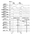
そして、図24〜図27は、入賞球信号処理時の主制御基板31および賞球制御基板37に入出力される信号を示すタイミング図である。なお、図24は賞球払出が正常に行われた場合の例、図25は主制御基板31のCPU56が払出個数不足と判断した場合の例、図26は主制御基板31のCPU56が払出個数過多と判断した場合の例、図27は入賞発生と玉貸し要求とが重なった場合の例を示す。
【0087】
まず、図16〜図18のフローチャートを参照して、主制御基板31における入賞球信号処理を説明する。上述したように、入賞球信号処理は2msに1回実行される。最初に、使用される各タイマについて説明する。
(1)タイマT1:賞球カウントスイッチオフ時にセットされ、タイムアウトすると払出個数のチェックが行われる。
(2)タイマT5:エラー検出時にセットされ、タイムアウトするまでエラー表示が行われる。
(3)タイマT6:タイムアウトする度に繰り返し再起動され、タイムアウト時に累積エラー回数が所定回数を越えていたら復帰不能なエラーとなる。
(4)タイマT7:入賞球排出ソレノイド127の駆動開始時にスタートされ、タイムアウトするまでに入賞球の排出が確認されなければエラーと判定される。
【0088】
入賞球信号処理において、主制御基板31におけるCPU56は、まず、タイマT6がタイムアウトしたか否か確認する(ステップS101)。タイムアウトしていた場合には、賞球エラーカウンタの値をチェックする(ステップS102)。賞球エラーカウンタの値が所定値を越えていた場合には、エラー状態に入る(ステップS103)。エラー状態では、基本回路53はホールト状態(HALT状態)になる。例えば、動作停止フラグをセットする。動作停止フラグがセットされた場合には、例えば、図14に示された初期化処理(ステップS2)において、ホールト状態(例えば同一番地にジャンプ)とされる。
【0089】
タイマT6がタイムアウトしたときに、賞球エラーカウンタの値が所定回を越えていなければ、賞球エラーカウンタは初期化され(ステップS104)、再度タイマT6がスタートされる(ステップS105)。
【0090】
後述するように、賞球エラーカウンタの値は、賞球個数の過多が検出されるとカウントアップされる。従って、所定時間内に(タイマT6のカウントアップ時間内に)所定回数を越える賞球過多エラーが生ずると、定期リセット信号によっても解除されない状態になる。このように、賞球過多エラーが生じたときに直ちにホールト状態とならず、頻繁に賞球過多エラーが生じた場合にホールト状態となるように構成すると、一時的生じ自然復旧するようなエラーでは遊技機は動作不能状態にならない。また、頻繁に賞球過多エラーが生ずる場合には点検等を要することが多いので、そのような場合には遊技機が動作不能状態になるようにすることができる。
【0091】
なお、ここでは、エラー発生とは無関係にタイマT6をスタートさせタイマT6がタイムアウトする度に、時間T6における発生エラー数をチェックするようにしたが、エラーが発生するとタイマをスタートさせる等の他の監視方法を用いてもよい。要するに、所定時間内に所定回を越えるエラーが発生したことを検出できれば、どのような監視方法を用いてもよい。
【0092】
次いで、CPU56は、タイマT7が動作中であるか否か確認する(ステップS106)。動作中であれば、タイマT7がタイムアウトしたか否か確認する(ステップS107)。タイマT7がタイムアウトした場合には、入賞球排出ソレノイド127の駆動開始後所定時間内に入賞球が排出されなかったことになるのでエラーとする(ステップS108)。タイマT7がタイムアウトしていなければ、入賞球検出スイッチ122がオフしたか否か確認する(ステップS110)。オフしていれば、入賞球排出ソレノイド127の駆動を停止するとともに(ステップS111)、タイマT7を停止する(ステップS112)。
【0093】
次に、賞球払出中フラグがオンしているか否か確認する(ステップS115)。オンしている場合には、ステップS130に移行する。賞球払出中フラグがオンしていない場合には、入賞球検出スイッチ122がオンしているか否か確認する(ステップS116)。オンしていなければ処理を終了する。オンしていれば、カウントスイッチ23および始動口スイッチ17の状態を確認する(ステップS117,S119)。なお、入賞球検出スイッチ122のオンが確認された時点は、図24においてS1およびS2で示されている。
【0094】
この実施の形態では、大入賞口を経た入賞については15個の賞球を払い出し、始動入賞口14を経た入賞については6個の賞球を払い出し、その他の入賞口24および入賞球装置を経た入賞については10個の賞球を払い出すとする。よって、カウントスイッチ23がオンしていたときには賞球予定数に15を設定し(ステップS118)、始動口スイッチ17がオンしていたときには賞球予定数に6を設定する(ステップS120)。その他の場合には、賞球予定数に10を設定する(ステップS121)。なお、カウントスイッチ23および始動口スイッチ17がオンしたことは、図14に示されたスイッチ処理(ステップS10)で検出され、所定のRAM領域にそのことが記憶されている。
【0095】
そして、CPU56は、賞球予定数に応じた賞球個数信号を出力する(ステップS122)。なお、賞球制御基板37における賞球制御CPU372は、賞球個数信号で指定された個数の賞球払出制御を行う。ここで、CPU56は、入賞球検出スイッチ122がオフしていないかどうか確認する(ステップS123)。オフしていたら、入賞球排出処理を開始していないにも関わらず入賞球が抜けたことになるのでエラーとする(ステップS124)。エラーでなければ、入賞球処理装置115における玉止部130aに停留している入賞球を排出するために入賞球排出ソレノイド127の駆動を開始する(ステップS125)。
【0096】
そして、CPU56は、賞球払出中フラグをオンしておく(ステップS126)。さらに、入賞球排出監視のためのタイマT7をスタートし(ステップS127)、処理を終了する。なお、次に、入賞球信号処理が実行されると、ステップS110で入賞球検出スイッチ122のオフ確認が行われるとともに、賞球払出中フラグがオンしているので、ステップS113からステップS130に移行する。
【0097】
ステップS130において、CPU56は、エラー表示フラグがオンしているか否か確認する。オンしていれば、ステップS147に移行する。なお、エラー表示フラグについては後で説明する。エラー表示フラグがオンしていなければ、賞球カウントスイッチ(a)がオンするのを待つ(ステップS131)。賞球カウントスイッチ(a)のオンを検出すると、賞球カウントスイッチ(a)のオフを待ち(ステップS132)、オフしたら賞球カウント数を+1する(ステップS133)。
【0098】
そして、タイマT1を起動する(ステップS134)。タイマT1は、図24に示された賞球カウントスイッチ(a)の出力がオンした後オフする度に起動または再スタートされる。なお、賞球カウントスイッチ(a)および賞球カウントスイッチ(b)の出力は、実際には賞球カウントスイッチ301A,301Bの出力のオア(OR)をとったものに相当する。また、賞球カウントスイッチ(a)の出力は主制御基板31の側での信号であり、賞球カウントスイッチ(b)の出力は賞球制御基板37の側での信号であるが(図15参照)、ともに賞球カウントスイッチ301A,301Bの出力のオアをとったものである。
【0099】
ステップS131において賞球カウントスイッチ(a)がオンしていなければ、タイマT1が動作中か否か確認する(ステップS135)。タイマT1が動作中であれば、CPU56は、タイマT1がタイムアウトしたか否か確認する(ステップS140)。タイムアウトしていなければ処理を終了する。なお、次に、入賞球信号処理が実行されると、賞球払出中フラグがオンしているので、やはりステップS113からステップS130に移行する。
【0100】
タイマT1の値(起動時からタイムアウトするまでの時間)は、正常に払出が行われている場合には払出周期(賞球カウントスイッチ(a)がオンしてから次にオンするまでの期間)よりも長く設定されている。従って、正常に払出が行われているときには、最後の払出を除いて、タイマT1がタイムアウトするよりも前に、次の賞球カウントスイッチ(a)のオン(ステップS131)が発生する。すなわち、正常に払出が行われているときには、タイマT1は、最後の払出が行われた後に初めてタイムアウトする。
【0101】
ステップS140において、タイマT1がタイムアウトすると、CPU56は、賞球カウント数と賞球予定数とを比較する(ステップS141)。正常に払出が完了した場合には、それらは一致する。従って、賞球個数信号をオフ状態にし(ステップS142)、賞球払出フラグをオフして処理を終了する(ステップS143)。なお、図24に示された例では、入賞球検出スイッチ122の1回目のオンにもとづいて上述した処理が行われ賞球個数信号がオフ状態になったときには、既に入賞球検出スイッチ122はオンしている(検知2回目)。よって、次に、入賞球信号処理が実行されると、ステップS101→S106→S110→S115→S116と進み、直ちに入賞球検出スイッチ122の検知2回目が認識されて、上述した処理が再度実行される。
【0102】
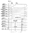
タイマT1がタイムアウトしたときに賞球カウント数と賞球予定数とが一致していなかった場合には、CPU56は、どちらが多いのかチェックする(ステップS145)。賞球カウント数が賞球予定数に満たない場合、すなわち払出不足と判断される場合には、処理を終了する。従って、賞球個数信号のオン状態が継続され、賞球払出フラグもオンのままである。なお、この状態は、図25に「賞球動作1回目」で示された部分のT1タイムアウトの時点に相当する。
【0103】
あとで詳しく説明するが、賞球制御用CPU371は、所定個の払出が完了したと認識して賞球モータ289Aを停止した後に所定時間が経過しても賞球個数信号がオフしない場合には、さらに1個の賞球払出制御を行う。すなわち、再度賞球カウントスイッチ(a)がオンする。
【0104】
次に、入賞球信号処理が実行されると、賞球払出中フラグがオンしているので、ステップS113からステップS130に移行する。そして、ステップS131で賞球カウントスイッチ(a)のオンが検出された後に賞球カウントスイッチ(a)がオフすると、CPU56は、賞球カウント数を+1する(ステップS133)。そして、タイマT1を再スタートする(ステップS134)。そして、ステップS140でタイマT1のタイムアウトが検知されると、賞球カウント数と賞球予定数とが再度比較される。ここで一致すれば入賞球検出スイッチ122の検知1回目にもとづく賞球払出処理は完了する。
【0105】
図25ではタイマT1の1回目のタイムアウトがQ1の時点として示されている。従って、図25には、この時点でも賞球カウント数が賞球予定数に満たない例が示されていることになる。その場合には、CPU56は、再び、賞球個数信号をオフ状態にせず、かつ、賞球払出フラグをオフせずに処理を終了する。すると、賞球制御用CPU371は、所定時間が経過しても賞球個数信号がオフしないことを認識して、再度1個の賞球払出制御を行う。CPU56は、その払出にもとづく賞球カウントスイッチ(a)のオンおよびオフを検出して、賞球カウント数を+1し(ステップS133)、タイマT1を起動する(ステップS134)。そして、タイマT1のタイムアウト時に、再び賞球カウント数と賞球予定数とを比較する。ここで一致すれば入賞球検出スイッチ122の検知1回目にもとづく賞球払出処理は完了する。図25ではこの時点のタイマT1のタイムアウトがQ2として示されている。すなわち、この時点で賞球払出処理が完了した例が示されている。
【0106】
ステップS145において、賞球カウント数が賞球予定数よりも多い場合、すなわち払出過多と判断される場合には、賞球個数信号をオフ状態にし(ステップS146)、エラー表示処理を行う(ステップS147)。なお、この状態は、図26に「賞球動作1回目」で示された部分のT1タイムアウトの時点に相当する。
【0107】
図18は、エラー表示処理の一例を示すフローチャートである。エラー表示処理において、CPU56は、まず、タイマT5が動作中であるかどうか確認する(ステップS151)。動作中でなければ、エラー表示フラグをオンし(ステップS152)、エラー表示要求をセットする(ステップS153)。そして、タイマT5を起動する(ステップS154)。また、賞球エラーカウンタの値を+1する(ステップS155)。賞球エラーカウンタの値は、ステップS102でチェックされ、所定時間内にその値が所定値を越えると自動復旧しない完全エラー状態とされる。なお、エラー表示要求がセットされると、例えば、図14に示された表示制御データ設定処理(ステップS3)および表示制御データ出力処理(ステップS4)において、表示装置8にエラー表示がなされるように制御されたり、データ出力処理(ステップS5)においてスピーカ27からエラー報知音が発生されるように制御されたりする。
【0108】
そして、遊技状態が通常状態であるならば(ステップS156)、ホールト状態になる。通常状態とは、大当り遊技状態および可変表示部9に可変表示がなされている状態以外の状態である。なお、ホールト状態は、定期リセット信号によっても解除されない遊技制御停止状態であり、遊技機の電源がオフされ、電源再投入によって解除される。
【0109】
ステップS151においてタイマT5が動作中である場合には、CPU56は、タイマT5がタイムアウトしているか否か確認する(ステップS160)。タイムアウトした場合には、エラー表示要求をリセットするとともに(ステップS161)、エラー表示中フラグをオフする(ステップS162)。また、賞球払出フラグをオフする(ステップS163)。よって、遊技機は、再度入賞球検出と賞球払出制御を行える状態に復帰する。なお、エラー表示フラグがオンしているときには、遊技進行は中断されている。
【0110】
ステップS103のエラー状態(所定期間内に賞球エラーカウンタの値が所定値を越えた)、ステップS108のエラー状態(入賞球排出ソレノイド127を駆動したにも関わらず入賞球検出スイッチ122がオフしなかった=入賞球が抜けなかった)、およびステップS124のエラー状態(入賞球排出ソレノイド127を駆動していないにも関わらず入賞球検出スイッチ122がオンした=入賞球が抜けた)については、例えば、エラー表示やエラー報知が行われるとともに、ホールト状態になるように制御される。ホールト状態では、例えば、動作停止フラグがセットされる。動作停止フラグがセットされた場合には、例えば、図14に示された初期化処理(ステップS2)において、ホールト状態(例えば同一番地にジャンプ)とされる。
【0111】
以上のように、この実施の形態では、主制御基板31における基本回路53のCPU56が、実際の払出数が賞球予定数を越えたと判断したら、遊技制御が中断され、エラー報知がなされる。そして、タイマT5がタイムアウトしたら正常遊技状態に復帰する。また、そのようなエラー状態の発生が所定期間内に所定回を越えた場合には、電源断によらなければ復帰しない完全エラー状態とされる。さらに、例えば大当たり中や確率変動中等の遊技者にとって有利な状態となっていない通常状態では、直ちに完全エラー状態とされる。
【0112】
図19〜図22は、賞球制御基板37における賞球制御用CPU371の動作を示すフローチャートである。最初に、使用される各タイマについて説明する。(1)タイマT2:払出予定数までの払出が完了したと判断されたときにセットされ、タイムアウトしたときに賞球個数信号がオフしていなければ、さらに1個の払出制御が行われる。なお、主制御基板31の側で用いられるタイマT1との関係は、T1<T2である。
(2)タイマT11:賞球モータを駆動開始したとき、または1個の景品玉払出が終了したときにセットされ、タイムアウトすると賞球モータ位置センサ300Aのエラーとされる。すなわち、賞球モータ位置センサ300Aのオンチェックタイマである。
(3)タイマT12:賞球モータ位置センサ300Aがオンするとセットされ、タイムアウトすると賞球モータ位置センサ300Aのエラーとされる。すなわち、賞球モータ位置センサ300Aのオフチェックタイマである。
(4)タイマT13:賞球モータ位置センサ300Aがオフするとセットされ、賞球カウントスイッチ(b)がオンしないとタイムアウトしエラーと判定される。
(5)タイマT14:賞球カウントスイッチ(b)がオンするとセットされ、賞球カウントスイッチ(b)がオフしないとタイムアウトしエラーと判定される。
【0113】
賞球制御用CPU371は、カードユニット50から玉貸し要求信号を受けると(ステップS201)、玉貸しモータ289Cを駆動して所定個の貸し玉の払出を行う(ステップS202)。玉貸しモータ289Cの駆動方法については既に説明したので、ここでは説明を省略する。従って、図27に示すように、カードユニット50から玉貸し要求信号を受けた場合には、賞球制御用CPU371は玉貸し動作に専念するために、主制御基板31からの賞球個数信号にもとづく賞球要求は待たされる。上述したように、玉払出装置97において賞球機構部分97Aと玉貸し機構部分97Cとは別個に設けられているので同時動作させることも可能であるが、この実施の形態のように、一時には片方のみを制御することによって玉払出制御は複雑化しない。
【0114】
玉貸し要求信号を受けていない場合には、賞球制御用CPU371は、賞球個数信号が出力されているか否か確認する(ステップS203)。賞球個数信号が出力されていれば、賞球個数信号が示す数を払出予定数に設定するとともに(ステップS204)、賞球モータ289Aを駆動開始する(ステップS205)。なお、払出予定数は、賞球制御用マイクロコンピュータにおけるRAM領域に設定される。そして、賞球制御用CPU371は、タイマT11を起動する(ステップS206)。
【0115】
その後、賞球制御用CPU371は、賞球モータ位置センサ300Aがオンするのを待つ(ステップS210)。オンする前にタイマT11がタイムアウトするとエラー処理に移行する(ステップS211,S212)。賞球モータ位置センサ300Aがオンすると、タイマT11を停止して(ステップS213)、タイマT12を起動する(ステップS214)。その後、賞球制御用CPU371は、賞球モータ位置センサ300Aがオフするのを待つ(ステップS215)。オフする前にタイマT12がタイムアウトするとエラー処理に移行する(ステップS216,S212)。
【0116】
賞球モータ位置センサ300Aがオフすると、タイマT12を停止して(ステップS217)、タイマT13を起動する(ステップS218)。そして、賞球カウントスイッチ(b)がオンするのを待つ(ステップS221)。既に説明したように、賞球カウントスイッチ(b)の出力は、実際には賞球カウントスイッチ301A,301Bの出力のオア(OR)をとったものに相当する。従って、どちらの賞球カウントスイッチ301A,301Bがオンしても、賞球カウントスイッチ(b)の出力はオン状態になる。賞球カウントスイッチ(b)の出力がオンする前にタイマT13がタイムアウトするとエラー処理に移行する(ステップS222,S212)。
【0117】
賞球カウントスイッチ(b)の出力がオン状態になると、タイマT13を停止して(ステップS223)、タイマT14を起動する(ステップS224)。そして、賞球カウントスイッチ(b)がオフするのを待つ(ステップS225)。賞球カウントスイッチ(b)がオフする前にタイマT14がタイムアウトするとエラー処理に移行する(ステップS226,S212)。タイマT14がタイムアウトする前に賞球カウントスイッチ(b)がオフした場合には、タイマT14を停止して(ステップS227)、賞球個数カウンタを+1する(ステップS228)。
【0118】
以上の処理によって、賞球モータ289Aを駆動しているときに、所定時間内に賞球モータ位置センサ300Aがオンしなかったりオフしなかった場合には、エラーと判定される。賞球モータ位置センサ300Aがオンしなかったりオフしなかった場合には、賞球機構部分97Aのスクリュー288Aが回転しなかったり、玉詰まりが生じてスクリュー288Aの回転が阻害されている場合等が考えられるからである。
【0119】
また、賞球モータ位置センサ300Aの出力が正常であるにも関わらず、賞球機構部分97Aの玉送り水平路284a,284bの下方に設けられている賞球カウントスイッチ301A,301B(=賞球カウントスイッチ(b))がオンしなかった場合には、賞球カウントスイッチ301A,301Bの故障等が考えられるので、やはりエラーと判定される。そして、賞球カウントスイッチ(b)がオフしなかった場合には、賞球カウントスイッチ301A,301Bの近傍で玉詰まりが生じている等が考えられるので、やはりエラーと判定される。
【0120】
ステップS228において賞球個数カウンタを+1すると、賞球制御用CPU371は、賞球個数カウンタの値と払出予定数とを比較する(ステップS229)。賞球個数カウンタの値が払出予定数に達していなければ、次の景品玉を払い出すためにステップS206に戻る。賞球個数カウンタの値と払出予定数とが一致すれば、主制御基板31からの賞球個数信号で指令された個数の景品玉の払出制御が完了したことになるので、賞球モータ289Aの駆動を停止する(ステップS230)。
【0121】
既に説明したように、主制御基板31における基本回路53のCPU56は、賞球カウントスイッチ301A,301Bの出力すなわち賞球カウントスイッチ(a)の出力を監視している。上述したように賞球制御基板37の賞球制御用CPU371も賞球カウントスイッチ301A,301Bの出力を導入して賞球カウントスイッチ(b)の出力として監視しているのであるが、両者で監視することによって、景品玉の払出制御はより確実になる。例えば、賞球カウントスイッチ301A,301Bから賞球制御基板37に至るケーブルにノイズがのって賞球カウントスイッチ(b)の出力に誤りが生じても、正しく払出制御を実行することができる。
【0122】
例えば、図25に示されたように、実際には(払出予定数−2)個の景品玉しか払い出されていないにも関わらず賞球制御用CPU371が払出予定数まで払い出して賞球モータ289Aを停止してしまったような場合であっても、主制御基板31におけるCPU56の制御によって不足の2個を払い出すことができる。そのような制御を行うために、CPU56は、タイマT1を用いて、タイマT1がタイムアウトしたときに賞球カウントスイッチ(a)のオン回数が賞球予定数に一致したかどうか確認していた。そして、実際の払出数が不足していると判断した場合には、賞球個数信号をオフ状態にしないことによって、払出数の不足を賞球制御基板37に伝えていた。
【0123】
そこで、賞球制御用CPU371は、T1よりも長い時間でタイムアウトするタイマT2を用いて、払出数の不足が伝えられるのかどうか監視する。すなわち、賞球制御用CPU371は、タイマT2を起動し(ステップS231)、賞球個数信号がオフするか否か確認する(ステップS232)。タイマT2がタイムアウトする前に賞球個数信号がオフすれば、主制御基板31のCPU56が賞球カウントスイッチ(a)のオン回数が賞球予定数に一致したことを確認したことになるので、タイマT2を停止して(ステップS234)、初期状態であるステップS201に戻る。
【0124】
しかし、賞球個数信号がオフする前にタイマT2がタイムアウトした場合には(ステップS233)、主制御基板31のCPU56が、実際の払出数が不足していると判断したことになる。そこで、賞球制御用CPU371は、賞球モータ289Aを再度起動して(ステップS241)、1個の景品玉を払い出す。具体的には、タイマT11およびタイマT12を用いて監視しつつ賞球モータ位置センサ300Aのオンおよびオフを確認した後(ステップS241〜S248)、タイマT13を用いて監視しつつ賞球カウントスイッチ(b)がオンするのを待つ(ステップS249,S251,S252,S212)。
【0125】
賞球カウントスイッチ(b)がオンしたら、タイマT13を停止した後(ステップS253)、タイマT14を用いて監視しつつ賞球カウントスイッチ(b)がオフするのを待つ(ステップS255,S256,S212)。そして、賞球カウントスイッチ(b)の出力がオフ状態になると、タイマT14を停止して(ステップS257)、ステップS230に移行する。よって、賞球モータ289Aが停止され(ステップS230)、賞球個数信号のオフを監視するためのタイマT2が起動される(ステップS231)。
【0126】
以上のように、賞球制御基板37において、賞球制御用CPU371は、主制御基板31からの賞球個数信号で指定された個数の景品玉を、動作量検出手段としての賞球モータ位置センサ300Aの出力を用いて払い出す。そして、主制御基板31から、賞球個数信号をオフ状態にしないことによって払出数の不足が通知されると1個の払出を行い、それでも賞球個数信号がオフ状態にならないことによって払出数がまだ不足しているが通知されるとさらに1個の払出を行う。このような制御が、賞球個数信号がオフ状態になるまで、賞球モータ289Aの駆動を断続的に行うことにより繰り返される。すなわち、主制御基板31のCPU56が正しい個数の払出が行われたことを確認するまで繰り返される。さらに、複数の不足分の払出を行う場合に、払出が行われる間隔が通常の払出間隔よりも長く設定されている。
【0127】
図23は、ステップS212のエラー処理の一例を示すフローチャートである。この例では、賞球制御用CPU371は、エラー種類に応じたコードをエラー表示用LED374(図15参照)に表示するとともに(ステップS261)、ブザー基板75に対してブザーを鳴動させる指示を出す(ステップS262)。その後、賞球制御用CPU371は、ホールト状態になる。
【0128】
以上の説明を要約すると、このパチンコ遊技機1は、以下のような特徴を有する。
1.主制御基板31の遊技制御手段は、賞球検出数が賞球予定数に満たないことを検出した場合には、賞球制御基板37における賞球制御手段に対して不足分を1個ずつ払い出すように指示する。賞球制御手段は、その指示に応じて賞球モータ289Aを駆動して1個ずつ景品玉を払い出す。このとき、1個の払出に要する時間は、通常の払出時に比べて長く設定されるので、確実に不足分の払出が実行される。
【0129】
2.玉払出装置97において賞球機構部分97Aと玉貸し機構部分97Cとは別個に設けられている。よって、入賞にもとづく景品玉と貸し玉とを区別して集計管理することが容易になる。また、そのような構成であっても、賞球機構部分97Aの払出能力は従来の構成に比べて低下していない。そして、賞球機構部分97Aと玉貸し機構部分97Cとは同一方式で構成されているので、設計コストがアップしたりすることはない。
【0130】
3.主制御基板31の遊技制御手段は、賞球検出数が賞球予定数よりも多いことを検出した場合には、エラー報知処理を行う。そして、エラー報知後所定時間が経過すると自動復旧するので、遊技の進行に悪影響を与えることなくエラー発生を報知できる。また、遊技者に不利にならない範囲で、または、エラーが頻発するような状況では、自動復旧しない完全エラー状態にして、遊技客および遊技店に混乱を与えるような事態が回避される。
【0131】
4.賞球カウントスイッチの検出信号が主制御基板31の遊技制御手段および賞球制御基板37における賞球制御手段に対して出力されている。よって、一方にのみ出力される構成に比べて、より信頼性の高い賞球払出制御を行うことができる。また、賞球制御基板37における賞球制御手段は、賞球カウントスイッチの検出信号による払出数カウントに加えて、賞球モータ289Aの動作量を検出する動作量検出手段の出力も用いて払出制御を行うので、さらに信頼性の高い賞球払出制御を行うことができる。
【0132】
【発明の効果】
以上のように、本発明によれば、遊技の進行を制御し、入賞に応じて払い出すべき賞球の数を示す賞球個数信号を出力する遊技制御手段と、賞球の払い出しを行う賞球払出装置と、賞球個数信号にもとづき賞球個数信号が示す払出予定数分の駆動を賞球払出装置にさせる賞球払出処理を実行する賞球制御手段と、賞球払出装置によって払い出された賞球の数を確認する賞球確認手段とを備え、賞球制御手段は、賞球払出処理を終えた後、賞球確認手段が払出予定数に対する払出数の不足を検知すると、賞球払出装置を再度駆動させて不足している賞球を払い出す処理を実行し、不足している賞球を払い出す場合には、タイムアウトするまでの時間が正常に払出が行われている場合の払出周期よりも長く設定されているタイマを賞球払出装置の駆動が停止した時に起動させ、タイマがタイムアウトしたときに賞球払出装置を再度駆動する処理を実行することにより1個の払い出しに要する時間を通常の払出のときよりも長くするように構成したので、払出数不足を検出して確実に不足分が払い出される効果がある。
【0134】
遊技制御手段に設けられた賞球確認手段が払出数の不足を検知したときには賞球個数信号を継続して出力し続けることによって払出数の不足を賞球制御手段に通知するように構成されている場合には、特別なインタフェースを追加せずに不足数を賞球制御手段に通知することができる効果がある。
【図面の簡単な説明】
【図1】 パチンコ遊技機を正面からみた正面図である。
【図2】 パチンコ遊技機1の内部構造を示す全体背面図である。
【図3】 パチンコ遊技機の遊技盤を背面からみた背面図である。
【図4】 入賞球処理装置の入賞球が停留している状態を示す断面図である。
【図5】 入賞球処理装置の停留されていた入賞球が開放された状態を示す断面図である。
【図6】 機構板の中間ベースユニットと玉払出装置の構成を示す断面図である。
【図7】 玉払出装置における賞球機構部分を示す分解斜視図である。
【図8】 玉払出装置における賞球機構部分を示す部分断面図である。
【図9】 玉払出装置における賞球機構部分を示す部分断面図である。
【図10】 玉払出装置における玉貸し機構部分を示す分解斜視図である。
【図11】 玉払出装置における玉貸し機構部分を示す部分断面図である。
【図12】 中間ベースユニットと玉払出装置の他の構成例を示す断面図である。
【図13】 主制御基板における回路構成の一例を示すブロック図である。
【図14】 主制御基板の基本回路のメイン処理を示すフローチャートである。
【図15】 賞球制御基板およびそれに関連する構成要素を示すブロック図である。
【図16】 主制御基板における入賞球信号処理を示すフローチャートである。
【図17】 主制御基板における入賞球信号処理を示すフローチャートである。
【図18】 入賞球信号処理におけるエラー処理を示すフローチャートである。
【図19】 賞球制御基板の賞球制御用CPUの動作を示すフローチャートである。
【図20】 賞球制御基板の賞球制御用CPUの動作を示すフローチャートである。
【図21】 賞球制御基板の賞球制御用CPUの動作を示すフローチャートである。
【図22】 賞球制御基板の賞球制御用CPUの動作を示すフローチャートである。
【図23】 賞球制御基板の賞球制御用CPUのエラー処理を示すフローチャートである。
【図24】 正常な入賞球信号処理時の主制御基板および賞球制御基板に入出力される信号を示すタイミング図である。なお、図24は賞球払出が正常に行われた場合の例、図25は主制御基板31のCPU56が払出個数不足と判断した場合の例、図26は主制御基板31のCPU56が払出個数過多と判断した場合の例、図27は玉貸し処理が行われているときに入賞が発生した場合の例を示す。
【図25】 払出個数不足の場合の入賞球信号処理時の主制御基板および賞球制御基板に入出力される信号を示すタイミング図である。
【図26】 払出個数過多の場合の入賞球信号処理時の主制御基板および賞球制御基板に入出力される信号を示すタイミング図である。
【図27】 入賞発生と玉貸し要求とが重なった場合の主制御基板および賞球制御基板に入出力される信号を示すタイミング図である。
【符号の説明】
31 遊技制御基板(主制御基板)
37 賞球制御基板
53 基本回路
56 CPU
97 玉払出装置
97A 賞球機構部分
97C 玉貸し機構部分97C
289A 賞球モータ
289C 玉貸しモータ
300A 賞球モータ位置センサ
300C 玉貸しモータ位置センサ
301A〜301C 賞球カウントスイッチ[0001]
BACKGROUND OF THE INVENTION
The present invention relates to a gaming machine such as a pachinko gaming machine or a coin gaming machine in which a game is performed in accordance with a player's operation, and more particularly to a gaming machine in which a game is performed in accordance with a player's operation in a gaming area on a gaming board. .
[0002]
[Prior art]
As a gaming machine, there is provided a winning ball processing device for processing a winning game ball in a winning area provided in the gaming area, and a predetermined number of prize balls are awarded for each winning ball processed by the winning ball processing device. There is something to be paid out to the player. The winning ball processing device is provided with a winning ball holding means for holding a winning ball and a winning ball detection means for detecting a winning ball held by the winning ball holding means. Such a gaming machine has a game control means for controlling the gaming state and a prize ball payout means for paying out a prize ball.
[0003]
A detection signal from the winning ball detection means is input to the winning ball payout means. When receiving the detection signal from the winning ball detection means, the winning ball payout means sends a winning ball detection signal indicating that a winning ball has been detected to the game control means. Then, the game control means returns a prize ball number signal indicating the number of prize balls for the prize to the prize ball payout means. The prize ball payout means drives the ball payout device so that the number of premium balls specified by the prize ball number signal is paid out.
[0004]
In such a gaming machine, a player can play a game using both a game ball lent to the player and a prize ball acquired by the player. Therefore, in general, the ball dispensing device is used both as a prize ball dispensing device and a ball lending dispensing device. That is, when the game control means is instructed to pay out a predetermined number of prize balls, the prize ball payout means drives the ball payout device by the designated number. Further, when a ball lending request signal is received from a prepaid card unit or the like, the ball dispensing device is driven so that a predetermined number of game balls are dispensed.
[0005]
In addition, since the number of winning balls and the number of game balls to be lent out for each winning must be predetermined values, the ball payout device is provided with sensor means for detecting the number of game balls paid out. . The prize ball payout device uses sensor means to monitor the number of game balls corresponding to a predetermined number set in advance.
[0006]
[Problems to be solved by the invention]
Detects shortage of prize ballsThen, there is a gaming machine that executes a process of driving the ball payout device again and paying out the missing prize balls. However, if the insufficiency is paid out, no effort is made to pay out the deficiency.
[0007]
Accordingly, an object of the present invention is to provide a gaming machine that can detect the shortage of the number of payout balls and can reliably pay out the shortage when the shortage of the number of payouts is detected.
[0008]
[Means for Solving the Problems]
A gaming machine according to the present invention is a gaming machine in which a gaming area is provided on a gaming board, and a predetermined number of prize balls are paid out in accordance with winning in a winning area provided in the gaming area, and the progress of the game is controlled. The game control means for outputting a prize ball number signal indicating the number of prize balls to be paid out according to the winning, the prize ball payout device for paying out the prize balls, and the prize ball number signal based on the prize ball number signal. A prize ball payout device that executes a prize ball payout process for causing the prize ball payout device to drive for the number of payouts indicated, and a prize ball check means that checks the number of prize balls paid out by the prize ball payout device. The prize ball control means, after finishing the prize ball payout processing, when the prize ball confirmation means detects an insufficient number of payouts with respect to the expected payout quantity, drives the prize ball payout device again to pay out the missing prize balls. Execute the processWhen paying out missing prize balls, when the driving of the prize ball dispensing device stops a timer that is set longer than the payout period when the time until timeout is normally paid out By starting and executing the process of driving the prize ball dispensing device again when the timer times outIt is characterized in that the time required for one payout is made longer than that during normal payout.
[0010]
The way to check the prize ballPlayProvided in the technique control means,awardIf the ball check means detects that the number of payouts is insufficient,NumberIt may be configured to notify the prize ball control means of a shortage of the number of payouts by continuously outputting the signal.
[0012]
DETAILED DESCRIPTION OF THE INVENTION
Hereinafter, an embodiment of the present invention will be described with reference to the drawings.
First, the overall configuration of a pachinko gaming machine that is an example of a gaming machine will be described. 1 is a front view of the
[0013]
As shown in FIG. 1, the
[0014]
Near the center of the
[0015]
An opening /
[0016]
The
[0017]
The
[0018]
The hit ball fired from the hit ball launching device enters the
[0019]
If the combination of images at the time of the stop is a combination of jackpot symbols, the game shifts to a jackpot gaming state. That is, the opening /
[0020]
When the combination of images in the
Further, when the stop symbol on the
[0021]
Next, the structure of the back surface of the
On the back surface of the
[0022]
The
[0023]
A ball
[0024]
The
[0025]
On the further downstream side of the
[0026]
[0027]
A
[0028]
On the rear side of the lower base unit 163 (the side far from the game board 6), a prize
[0029]
Under the
[0030]
FIG. 3 is a rear view of the game board of the
[0031]
Signals from the winning
[0032]
4 and 5 are cross-sectional views showing the configuration of the winning
The winning
[0033]
Further, the first
[0034]
A ball stop 124 a is formed at the upper part of the tip end side of the first
[0035]
Next, the operation of the winning
In a normal state where the
[0036]
In addition, when the next winning ball flows while the top winning ball P1 is stopped at the ball stopping portion 130a, the ball pressure of all winning balls is applied to the ball stopping portion 130a, but the load is the ball stopping portion 130a. It is received by the
[0037]
When the payout of the predetermined number of prize balls is completed, a driving signal is sent from the winning ball control microcomputer to the winning
[0038]
In this embodiment, the time from when the winning
As described above, the winning
[0039]
Next, the configuration of the
As shown in FIG. 6, connection
[0040]
A
[0041]
The central portion of the
[0042]
Below the
[0043]
Next, the configuration and operation of the
[0044]
First, the configuration and operation of the prize
[0045]
As shown in FIG. 7, the prize
[0046]
Further, the ball
[0047]
[0048]
A recess is formed at the tip of the
[0049]
When the
[0050]
Further, below the ball feed
[0051]
Next, the configuration and operation of the
[0052]
As shown in FIG. 10, the ball
[0053]
In addition, a ball
[0054]
A
[0055]
A recess is formed at the tip of the
[0056]
When the lending ball is placed on the ball feed
[0057]
In addition, a prize ball count switch 301C using, for example, a proximity switch is provided below the ball feed
[0058]
The
[0059]
As is clear from the configuration shown in FIGS. 7 to 11, the ball payout method of the prize
[0060]
FIG. 12 is a cross-sectional view showing another configuration example of the
As shown in FIG. 12, connection
[0061]
The central portion of the
[0062]
Below the
[0063]
The configuration of the
[0064]
In this state, the
[0065]
FIG. 13 is a block diagram illustrating an example of a circuit configuration in the
[0066]
Further, according to the data given from the
[0067]
The
[0068]
Further, the
[0069]
A ball hitting device for hitting and launching a game ball is driven by a drive motor 94 controlled by a circuit on the launch control board 91. Then, the driving force of the drive motor 94 is adjusted according to the operation amount of the
[0070]
Next, the operation of the gaming machine will be briefly described.
FIG. 14 is a flowchart showing the operation of the
[0071]
Next, processing for transmitting a predetermined command for generating sound and controlling LED lighting is performed on the lamp control board 35 and the sound control board 70, and the jackpot information is started to the hall management computer via the information output circuit 64. Processing for transmitting data such as information and probability variation information is performed (data output processing: step S5). Further, various abnormality diagnosis processes are performed by the self-diagnosis function provided in the
[0072]
Next, a process of updating each counter indicating each determination random number used for game control is performed (step S7). In step S7, the
[0073]
Next, the
[0074]
The
The
Thereafter, the
[0075]
FIG. 15 is a block diagram showing the prize
[0076]
The ball break
[0077]
Further, detection signals from the prize ball count switches 301A and 301B are also input to the I /
[0078]
The prize
[0079]
The prize ball control CPU 371 outputs a ball lending number signal indicating the number of lending balls to the
[0080]
Further, the detection signals of the prize ball count switches 301A and 301B and the detection signal of the ball lending count switch 301C are input to the prize
[0081]
The
[0082]
A ball lending switch signal and a return switch signal are given from the
[0083]
When the power of the
[0084]
As described above, all signals from the
The
[0085]
Hereinafter, processing when a hit ball is won in a winning area provided in the
[0086]
24 to 27 are timing charts showing signals inputted to and outputted from the
[0087]
First, the winning ball signal processing in the
(1) Timer T1: Set when the prize ball count switch is turned off, and when the time-out occurs, the number of payouts is checked.
(2) Timer T5: set when an error is detected, and an error is displayed until a timeout occurs.
(3) Timer T6: The timer T6 is repeatedly restarted every time it times out, and if the cumulative error count exceeds a predetermined number at the time of timeout, it becomes an unrecoverable error.
(4) Timer T7: Starts when driving the winning
[0088]
In the winning ball signal processing, the
[0089]
If the value of the prize ball error counter does not exceed a predetermined number when the timer T6 times out, the prize ball error counter is initialized (step S104), and the timer T6 is started again (step S105).
[0090]
As will be described later, the value of the prize ball error counter is counted up when an excessive number of prize balls is detected. Therefore, if an excessive number of prize balls exceeds a predetermined number of times within the predetermined time (within the count-up time of the timer T6), the state is not canceled even by the periodic reset signal. In this way, if a configuration is made so that a halt condition does not occur immediately when an excessive prize ball error occurs, but a halt condition occurs frequently when an excessive prize ball error occurs, an error that temporarily occurs and recovers naturally The gaming machine will not become inoperable. In addition, since there are many cases where inspection or the like is often required when there are excessive prize ball errors, the gaming machine can be rendered inoperable in such a case.
[0091]
Here, the timer T6 is started regardless of the occurrence of an error, and the number of generated errors at the time T6 is checked each time the timer T6 times out. However, when an error occurs, the timer is started. A monitoring method may be used. In short, any monitoring method may be used as long as it can detect that an error exceeding a predetermined number of times has occurred within a predetermined time.
[0092]
Next, the
[0093]
Next, it is confirmed whether or not a prize ball paying flag is on (step S115). If it is on, the process proceeds to step S130. If the winning ball payout flag is not turned on, it is checked whether or not the winning
[0094]
In this embodiment, 15 winning balls are paid out for winning through the big winning opening, 6 winning balls are paid out for winning through the
[0095]
Then, the
[0096]
Then, the
[0097]
In step S130, the
[0098]
Then, the timer T1 is started (step S134). The timer T1 is started or restarted each time the output of the prize ball count switch (a) shown in FIG. The outputs of the prize ball count switch (a) and the prize ball count switch (b) are actually equivalent to those obtained by taking the OR of the outputs of the prize ball count switches 301A and 301B. The output of the prize ball count switch (a) is a signal on the
[0099]
If the prize ball count switch (a) is not turned on in step S131, it is confirmed whether or not the timer T1 is operating (step S135). If the timer T1 is operating, the
[0100]
The value of the timer T1 (time from start-up to timeout) is the payout period (period from when the award ball count switch (a) is turned on to when it is turned on) when paying out normally. Is set longer than. Therefore, when the payout is normally performed, the next prize ball count switch (a) is turned on (step S131) before the timer T1 times out except for the last payout. That is, when the payout is normally performed, the timer T1 times out only after the last payout is performed.
[0101]
In step S140, when the timer T1 times out, the
[0102]
If the prize ball count number does not match the planned prize ball number when the timer T1 times out, the
[0103]
As will be described in detail later, when the prize ball control CPU 371 recognizes that a predetermined number of payouts have been completed and stops the prize ball motor 289A, the prize ball number signal does not turn off even after a predetermined time has elapsed. Further, one prize ball payout control is performed. That is, the prize ball count switch (a) is turned on again.
[0104]
Next, when the winning ball signal processing is executed, since the winning ball paying-in flag is on, the process proceeds from step S113 to step S130. When the prize ball count switch (a) is turned off after the prize ball count switch (a) is detected to be on in step S131, the
[0105]
In FIG. 25, the first timeout of the timer T1 is shown as the time point of Q1. Accordingly, FIG. 25 shows an example in which the number of prize balls is less than the planned number of prize balls even at this time. In that case, the
[0106]
In step S145, if the prize ball count is greater than the planned number of prize balls, that is, if it is determined that there is an excessive payout, the prize ball number signal is turned off (step S146), and error display processing is performed (step S147). ). This state corresponds to the time point of T1 timeout in the part indicated by “first prize ball movement” in FIG.
[0107]
FIG. 18 is a flowchart illustrating an example of error display processing. In the error display process, the
[0108]
If the gaming state is the normal state (step S156), the halt state is entered. The normal state is a state other than the big hit gaming state and the state in which variable display is made on the
[0109]
When the timer T5 is operating in step S151, the
[0110]
The error state of step S103 (the value of the prize ball error counter has exceeded a predetermined value within a predetermined period), the error state of step S108 (the prize
[0111]
As described above, in this embodiment, when the
[0112]
19 to 22 are flowcharts showing the operation of the prize ball control CPU 371 in the prize
(2) Timer T11: set when the driving of the prize ball motor is started or when one prize ball payout is completed, and when a time-out occurs, the prize ball
(3) Timer T12: Set when the prize ball
(4) Timer T13: Set when the prize ball
(5) Timer T14: Set when the winning ball count switch (b) is turned on, and when the winning ball count switch (b) is not turned off, a time-out occurs and it is determined as an error.
[0113]
When receiving the ball lending request signal from the card unit 50 (step S201), the winning ball control CPU 371 drives the
[0114]
When the ball lending request signal has not been received, the prize ball control CPU 371 checks whether or not a prize ball number signal is output (step S203). If the prize ball number signal is output, the number indicated by the prize ball number signal is set as the expected payout number (step S204), and the driving of the prize ball motor 289A is started (step S205). The planned payout number is set in a RAM area in the prize ball controlling microcomputer. Then, the prize ball control CPU 371 starts the timer T11 (step S206).
[0115]
Thereafter, the prize ball control CPU 371 waits for the prize ball
[0116]
When the prize ball
[0117]
When the output of the winning ball count switch (b) is turned on, the timer T13 is stopped (step S223) and the timer T14 is started (step S224). Then, it waits for the prize ball count switch (b) to turn off (step S225). If the timer T14 times out before the prize ball count switch (b) is turned off, the process proceeds to error processing (steps S226 and S212). If the prize ball count switch (b) is turned off before the timer T14 times out, the timer T14 is stopped (step S227), and the prize ball number counter is incremented by 1 (step S228).
[0118]
With the above processing, when the prize ball motor 289A is being driven, if the prize ball
[0119]
In addition, although the output of the prize ball
[0120]
When the prize ball number counter is incremented by 1 in step S228, the prize ball control CPU 371 compares the value of the prize ball number counter with the planned payout number (step S229). If the value of the prize ball number counter has not reached the planned payout number, the process returns to step S206 to pay out the next prize ball. If the value of the prize ball number counter matches the planned payout number, the payout control of the number of prize balls instructed by the prize ball number signal from the
[0121]
As already described, the
[0122]
For example, as shown in FIG. 25, the prize ball control CPU 371 pays out to the planned payout number even though only (scheduled payout number−2) prize balls are actually paid out, and the prize ball motor. Even if 289A is stopped, the two deficient items can be paid out by the control of the
[0123]
Therefore, the prize ball control CPU 371 monitors whether or not the shortage of the payout amount is transmitted using the timer T2 that times out in a time longer than T1. That is, the prize ball control CPU 371 activates the timer T2 (step S231) and checks whether or not the prize ball number signal is turned off (step S232). If the prize ball number signal is turned off before the timer T2 times out, the
[0124]
However, if the timer T2 times out before the prize ball number signal is turned off (step S233), the
[0125]
When the winning ball count switch (b) is turned on, the timer T13 is stopped (step S253), and then waiting for the turning off of the winning ball count switch (b) while monitoring using the timer T14 (steps S255, S256, S212). ). When the output of the prize ball count switch (b) is turned off, the timer T14 is stopped (step S257), and the process proceeds to step S230. Accordingly, the prize ball motor 289A is stopped (step S230), and the timer T2 for monitoring the prize ball number signal OFF is activated (step S231).
[0126]
As described above, in the prize
[0127]
FIG. 23 is a flowchart illustrating an example of error processing in step S212. In this example, the prize ball control CPU 371 displays a code corresponding to the error type on the error display LED 374 (see FIG. 15) (step S261) and issues an instruction to sound the buzzer to the buzzer board 75 (step S261). Step S262). Thereafter, the winning ball control CPU 371 enters a halt state.
[0128]
In summary, the
1. When the game control means of the
[0129]
2. In the
[0130]
3. When the game control means of the
[0131]
4). The detection signal of the prize ball count switch is output to the game control means of the
[0132]
【The invention's effect】
As described above, according to the present invention, a game control means for controlling the progress of a game and outputting a prize ball number signal indicating the number of prize balls to be paid out according to a winning, and a prize for paying out a prize ball. A payout by a prize ball payout device, a prize ball control means for executing a prize ball payout process for causing the prize ball payout device to drive for the number of payouts indicated by the prize ball number signal based on the prize ball number signal, and a prize ball payout device. Prize ball confirming means for confirming the number of prize balls received, and the prize ball control means, after finishing the prize ball payout process, when the prize ball confirming means detects a shortage of the number to be paid out, Run the ball payout device again to execute the process of paying out the missing prize balls,When paying out missing prize balls, when the driving of the prize ball dispensing device stops a timer that is set longer than the payout period when the time until timeout is normally paid out By starting and executing the process of driving the prize ball dispensing device again when the timer times outSince the time required for one payout is configured to be longer than the normal payout time,DetectThere is an effect that the deficit is paid out surely.
[0134]
When the prize ball confirmation means provided in the game control means detects that the number of payouts is insufficient,NumberIf the prize ball control means is configured to notify the prize ball control means of a shortage of the number of payouts by continuously outputting the signal, the prize ball control means is notified of the lack number without adding a special interface. There is an effect that can.
[Brief description of the drawings]
FIG. 1 is a front view of a pachinko gaming machine as viewed from the front.
FIG. 2 is an overall rear view showing the internal structure of the
FIG. 3 is a rear view of the game board of the pachinko gaming machine as viewed from the back.
FIG. 4 is a cross-sectional view showing a state where a winning ball of the winning ball processing apparatus is stopped.
FIG. 5 is a cross-sectional view showing a state where a winning ball that has been stopped by the winning ball processing apparatus is opened.
FIG. 6 is a cross-sectional view showing a configuration of an intermediate base unit of a mechanism plate and a ball dispensing device.
FIG. 7 is an exploded perspective view showing a prize ball mechanism portion in the ball dispensing apparatus.
FIG. 8 is a partial cross-sectional view showing a prize ball mechanism portion in the ball dispensing apparatus.
FIG. 9 is a partial sectional view showing a prize ball mechanism portion in the ball dispensing apparatus.
FIG. 10 is an exploded perspective view showing a ball lending mechanism portion in the ball dispensing apparatus.
FIG. 11 is a partial cross-sectional view showing a ball lending mechanism portion in the ball dispensing apparatus.
FIG. 12 is a cross-sectional view showing another configuration example of the intermediate base unit and the ball dispensing device.
FIG. 13 is a block diagram showing an example of a circuit configuration on the main control board.
FIG. 14 is a flowchart showing a main process of a basic circuit of a main control board.
FIG. 15 is a block diagram showing a prize ball control board and components related thereto.
FIG. 16 is a flowchart showing winning ball signal processing in the main control board.
FIG. 17 is a flowchart showing winning ball signal processing in the main control board.
FIG. 18 is a flowchart showing error processing in winning ball signal processing;
FIG. 19 is a flowchart showing the operation of the prize ball control CPU of the prize ball control board.
FIG. 20 is a flowchart showing the operation of the prize ball control CPU of the prize ball control board.
FIG. 21 is a flowchart showing the operation of the prize ball control CPU of the prize ball control board.
FIG. 22 is a flowchart showing the operation of the prize ball control CPU of the prize ball control board.
FIG. 23 is a flowchart showing error processing of a prize ball control CPU of a prize ball control board.
FIG. 24 is a timing diagram showing signals input to and output from the main control board and the prize ball control board during normal winning ball signal processing. 24 shows an example in which the winning ball payout is normally performed, FIG. 25 shows an example in which the
FIG. 25 is a timing diagram showing signals input to and output from the main control board and the prize ball control board during winning ball signal processing when the number of payouts is insufficient.
FIG. 26 is a timing chart showing signals input / output to / from the main control board and the prize ball control board at the time of winning ball signal processing when the number of payouts is excessive.
FIG. 27 is a timing diagram showing signals input to and output from the main control board and the prize ball control board when a winning occurrence and a ball lending request overlap.
[Explanation of symbols]
31 Game control board (main control board)
37 prize ball control board
53 Basic circuit
56 CPU
97 Ball dispenser
97A Prize ball mechanism
97C
289A Prize ball motor
289C Ball rental motor
300A Prize ball motor position sensor
300C ball lending motor position sensor
301A-301C Prize ball count switch
Claims (2)
遊技の進行を制御し、入賞に応じて払い出すべき賞球の数を示す賞球個数信号を出力する遊技制御手段と、
賞球の払い出しを行う賞球払出装置と、
前記賞球個数信号にもとづき前記賞球個数信号が示す払出予定数分の駆動を前記賞球払出装置にさせる賞球払出処理を実行する賞球制御手段と、
前記賞球払出装置によって払い出された賞球の数を確認する賞球確認手段とを備え、
前記賞球制御手段は、前記賞球払出処理を終えた後、前記賞球確認手段が払出予定数に対する払出数の不足を検知すると、前記賞球払出装置を再度駆動させて不足している賞球を払い出す処理を実行し、
不足している賞球を払い出す場合には、タイムアウトするまでの時間が正常に払出が行われている場合の払出周期よりも長く設定されているタイマを前記賞球払出装置の駆動が停止した時に起動させ、該タイマがタイムアウトしたときに前記賞球払出装置を再度駆動する処理を実行することにより1個の払い出しに要する時間を通常の払出のときよりも長くする
ことを特徴とする遊技機。A gaming machine in which a gaming area is provided on a gaming board, and a predetermined number of prize balls are paid out in accordance with winning in a winning area provided in the gaming area,
Game control means for controlling the progress of the game and outputting a prize ball number signal indicating the number of prize balls to be paid out in accordance with the winning;
A prize ball dispensing device for delivering a prize ball;
A prize ball control means for executing a prize ball payout process for causing the prize ball payout device to drive the number of times that the prize ball number signal indicates based on the prize ball number signal;
A prize ball confirmation means for confirming the number of prize balls paid out by the prize ball dispensing device;
The prize ball control means, after finishing the prize ball payout process, when the prize ball confirmation means detects a shortage of the number of payouts with respect to the expected payout number, drives the prize ball payout device again to make a shortage of prizes. Execute the process to pay out the ball,
When paying out the missing prize balls, the driving of the prize ball dispensing device has stopped the timer set to be longer than the payout cycle when the time until timeout is normally paid out. A game machine characterized in that a time required for one payout is made longer than that in a normal payout by executing a process for starting the prize ball payout device again when the timer times out .
前記賞球確認手段は、払出数の不足を検知した場合には賞球個数信号を継続して出力し続けることによって払出数の不足を賞球制御手段に通知する
請求項1記載の遊技機。The prize ball confirmation means is provided in the game control means,
The gaming machine according to claim 1, wherein when the shortage of the number of payouts is detected, the prize ball confirmation unit notifies the prizeball control unit of the shortage of the number of payouts by continuously outputting the prize ball number signal.
Priority Applications (1)
| Application Number | Priority Date | Filing Date | Title |
|---|---|---|---|
| JP21648598A JP4049899B2 (en) | 1998-07-15 | 1998-07-15 | Game machine |
Applications Claiming Priority (1)
| Application Number | Priority Date | Filing Date | Title |
|---|---|---|---|
| JP21648598A JP4049899B2 (en) | 1998-07-15 | 1998-07-15 | Game machine |
Publications (3)
| Publication Number | Publication Date |
|---|---|
| JP2000024243A JP2000024243A (en) | 2000-01-25 |
| JP2000024243A5 JP2000024243A5 (en) | 2006-06-15 |
| JP4049899B2 true JP4049899B2 (en) | 2008-02-20 |
Family
ID=16689178
Family Applications (1)
| Application Number | Title | Priority Date | Filing Date |
|---|---|---|---|
| JP21648598A Expired - Lifetime JP4049899B2 (en) | 1998-07-15 | 1998-07-15 | Game machine |
Country Status (1)
| Country | Link |
|---|---|
| JP (1) | JP4049899B2 (en) |
Families Citing this family (4)
| Publication number | Priority date | Publication date | Assignee | Title |
|---|---|---|---|---|
| JP4829400B2 (en) * | 2000-09-29 | 2011-12-07 | 株式会社ニューギン | Pachinko machine |
| JP4107083B2 (en) * | 2002-12-27 | 2008-06-25 | 株式会社日立製作所 | High-availability disk controller, its failure handling method, and high-availability disk subsystem |
| JP4683458B2 (en) * | 2004-09-29 | 2011-05-18 | ダイコク電機株式会社 | Game data management system |
| JP5431690B2 (en) * | 2008-07-07 | 2014-03-05 | 株式会社大一商会 | Pachinko machine |
Family Cites Families (5)
| Publication number | Priority date | Publication date | Assignee | Title |
|---|---|---|---|---|
| JP3128865B2 (en) * | 1991-06-17 | 2001-01-29 | 株式会社三洋物産 | Pachinko ball delivery control device |
| JPH05277247A (en) * | 1992-03-31 | 1993-10-26 | Sankyo Kk | Game machine |
| JP3233991B2 (en) * | 1992-06-26 | 2001-12-04 | 株式会社ソフィア | Gaming machine |
| JP2806319B2 (en) * | 1995-08-31 | 1998-09-30 | 株式会社竹屋 | Prize ball payout device for pachinko machines |
| JPH11319279A (en) * | 1998-05-11 | 1999-11-24 | Daiichi Shokai Co Ltd | Ball shooting game machine |
-
1998
- 1998-07-15 JP JP21648598A patent/JP4049899B2/en not_active Expired - Lifetime
Also Published As
| Publication number | Publication date |
|---|---|
| JP2000024243A (en) | 2000-01-25 |
Similar Documents
| Publication | Publication Date | Title |
|---|---|---|
| JP3443331B2 (en) | Gaming machine | |
| JP4049899B2 (en) | Game machine | |
| JP2002153646A (en) | Game machine | |
| JP3634647B2 (en) | Game machine | |
| JP2000033168A (en) | Game machine | |
| JP2002052151A (en) | Game machine | |
| JP4642176B2 (en) | Game machine | |
| JP2000024249A (en) | Game machine | |
| JP4322384B2 (en) | Game machine | |
| JP4056683B2 (en) | Game machine | |
| JP4731652B2 (en) | Game machine | |
| JP2002078942A (en) | Game machine | |
| JP4278746B2 (en) | Game machine | |
| JP3634704B2 (en) | Game machine | |
| JP3634703B2 (en) | Game machine | |
| JP5085673B2 (en) | Game machine | |
| JP2002078927A (en) | Game machine | |
| JP3596862B2 (en) | Ball game machine | |
| JP3545395B2 (en) | Recording medium processing machine and game system | |
| JP3596879B2 (en) | Recording medium processing machine and game system | |
| JP5576412B2 (en) | Game machine | |
| JP3596880B2 (en) | Recording media processing machine | |
| JP4527179B2 (en) | Game machine | |
| JP3596861B2 (en) | Ball game machines and gaming systems | |
| JP4527161B2 (en) | Game machine |
Legal Events
| Date | Code | Title | Description |
|---|---|---|---|
| A621 | Written request for application examination |
Free format text: JAPANESE INTERMEDIATE CODE: A621 Effective date: 20050622 |
|
| RD03 | Notification of appointment of power of attorney |
Free format text: JAPANESE INTERMEDIATE CODE: A7423 Effective date: 20060119 |
|
| A521 | Written amendment |
Free format text: JAPANESE INTERMEDIATE CODE: A523 Effective date: 20060428 |
|
| A131 | Notification of reasons for refusal |
Free format text: JAPANESE INTERMEDIATE CODE: A131 Effective date: 20060808 |
|
| A521 | Written amendment |
Free format text: JAPANESE INTERMEDIATE CODE: A523 Effective date: 20061006 |
|
| A131 | Notification of reasons for refusal |
Free format text: JAPANESE INTERMEDIATE CODE: A131 Effective date: 20070417 |
|
| A521 | Written amendment |
Free format text: JAPANESE INTERMEDIATE CODE: A523 Effective date: 20070618 |
|
| A02 | Decision of refusal |
Free format text: JAPANESE INTERMEDIATE CODE: A02 Effective date: 20070731 |
|
| A521 | Written amendment |
Free format text: JAPANESE INTERMEDIATE CODE: A523 Effective date: 20071001 |
|
| A911 | Transfer to examiner for re-examination before appeal (zenchi) |
Free format text: JAPANESE INTERMEDIATE CODE: A911 Effective date: 20071005 |
|
| TRDD | Decision of grant or rejection written | ||
| A01 | Written decision to grant a patent or to grant a registration (utility model) |
Free format text: JAPANESE INTERMEDIATE CODE: A01 Effective date: 20071120 |
|
| A61 | First payment of annual fees (during grant procedure) |
Free format text: JAPANESE INTERMEDIATE CODE: A61 Effective date: 20071128 |
|
| R150 | Certificate of patent or registration of utility model |
Free format text: JAPANESE INTERMEDIATE CODE: R150 |
|
| FPAY | Renewal fee payment (event date is renewal date of database) |
Free format text: PAYMENT UNTIL: 20101207 Year of fee payment: 3 |
|
| S531 | Written request for registration of change of domicile |
Free format text: JAPANESE INTERMEDIATE CODE: R313531 |
|
| FPAY | Renewal fee payment (event date is renewal date of database) |
Free format text: PAYMENT UNTIL: 20101207 Year of fee payment: 3 |
|
| R350 | Written notification of registration of transfer |
Free format text: JAPANESE INTERMEDIATE CODE: R350 |
|
| FPAY | Renewal fee payment (event date is renewal date of database) |
Free format text: PAYMENT UNTIL: 20101207 Year of fee payment: 3 |
|
| FPAY | Renewal fee payment (event date is renewal date of database) |
Free format text: PAYMENT UNTIL: 20101207 Year of fee payment: 3 |
|
| FPAY | Renewal fee payment (event date is renewal date of database) |
Free format text: PAYMENT UNTIL: 20111207 Year of fee payment: 4 |
|
| FPAY | Renewal fee payment (event date is renewal date of database) |
Free format text: PAYMENT UNTIL: 20111207 Year of fee payment: 4 |
|
| FPAY | Renewal fee payment (event date is renewal date of database) |
Free format text: PAYMENT UNTIL: 20121207 Year of fee payment: 5 |
|
| FPAY | Renewal fee payment (event date is renewal date of database) |
Free format text: PAYMENT UNTIL: 20121207 Year of fee payment: 5 |
|
| FPAY | Renewal fee payment (event date is renewal date of database) |
Free format text: PAYMENT UNTIL: 20131207 Year of fee payment: 6 |
|
| R250 | Receipt of annual fees |
Free format text: JAPANESE INTERMEDIATE CODE: R250 |
|
| R250 | Receipt of annual fees |
Free format text: JAPANESE INTERMEDIATE CODE: R250 |
|
| R250 | Receipt of annual fees |
Free format text: JAPANESE INTERMEDIATE CODE: R250 |
|
| EXPY | Cancellation because of completion of term |