JP4527179B2 - Game machine - Google Patents
Game machine Download PDFInfo
- Publication number
- JP4527179B2 JP4527179B2 JP2009113017A JP2009113017A JP4527179B2 JP 4527179 B2 JP4527179 B2 JP 4527179B2 JP 2009113017 A JP2009113017 A JP 2009113017A JP 2009113017 A JP2009113017 A JP 2009113017A JP 4527179 B2 JP4527179 B2 JP 4527179B2
- Authority
- JP
- Japan
- Prior art keywords
- control
- command
- lamp
- ball
- game
- Prior art date
- Legal status (The legal status is an assumption and is not a legal conclusion. Google has not performed a legal analysis and makes no representation as to the accuracy of the status listed.)
- Expired - Fee Related
Links
Images


Description
本発明は、遊技者の操作に応じて遊技が行われるパチンコ遊技機、コイン遊技機、スロット機等の遊技機に関し、特に、入賞が発生した場合に所定の有価価値を付与する遊技機に関する。 The present invention relates to a gaming machine such as a pachinko gaming machine, a coin gaming machine, or a slot machine in which a game is played in accordance with a player's operation, and more particularly to a gaming machine that gives a predetermined value when a winning occurs.
遊技機として、例えば遊技球などの遊技媒体を発射装置によって遊技領域に発射し、遊技領域に設けられている入賞口などの入賞領域に遊技媒体が入賞すると、所定個の賞球が遊技者に払い出されるものがある。さらに、表示状態が変化可能な可変表示部が設けられ、可変表示部における図柄等の識別情報の表示結果があらかじめ定められた特定の表示態様となった場合に所定の遊技価値を遊技者に与えるように構成されたものがある。 As a gaming machine, for example, a game medium such as a game ball is launched into a game area by a launching device, and when a game medium is won in a prize area such as a prize opening provided in the game area, a predetermined number of prize balls are given to the player. Some are paid out. Furthermore, a variable display unit capable of changing the display state is provided, and a predetermined game value is given to the player when the display result of the identification information such as symbols on the variable display unit becomes a predetermined specific display mode. There is something configured as follows.
なお、遊技価値とは、遊技機の遊技領域に設けられた可変入賞球装置の状態が打球が入賞しやすい遊技者にとって有利な状態になることや、遊技者にとって有利な状態となるための権利を発生させたりすることや、有価価値としての景品遊技媒体の払出の条件が成立しやすくなる状態になることである。 Note that the game value is the right that the state of the variable winning ball device provided in the gaming area of the gaming machine is advantageous for a player who is likely to win a ball, or the advantageous state for a player. Or a condition for paying out premium game media as a valuable value is easily established.
パチンコ遊技機では、特別図柄を表示する可変表示部の表示結果があらかじめ定められた特定の表示態様の組合せとなることを、通常、「大当り」という。大当りが発生すると、例えば、大入賞口が所定回数開放して打球が入賞しやすい大当り遊技状態に移行する。そして、各開放期間において、所定個(例えば10個)の大入賞口への入賞があると大入賞口は閉成する。そして、大入賞口の開放回数は、所定回数(例えば16ラウンド)に固定されている。なお、各開放について開放時間(例えば29.5秒)が決められ、入賞数が所定個に達しなくても開放時間が経過すると大入賞口は閉成する。また、大入賞口が閉成した時点で所定の条件(例えば、大入賞口内に設けられているVゾーンへの入賞)が成立していない場合には、大当り遊技状態は終了する。 In a pachinko game machine, the combination of a specific display mode with a predetermined display result of a variable display unit that displays special symbols is usually referred to as “big hit”. When a big hit occurs, for example, the big winning opening is opened a predetermined number of times, and the game shifts to a big hit gaming state in which a hit ball is easy to win. And in each open period, if there is a prize for a predetermined number (for example, 10) of the big prize opening, the big prize opening is closed. And the number of times the special winning opening is opened is fixed to a predetermined number (for example, 16 rounds). An opening time (for example, 29.5 seconds) is determined for each opening, and even if the number of winnings does not reach a predetermined number, the big winning opening is closed when the opening time elapses. Further, when a predetermined condition (for example, winning in the V zone provided in the big prize opening) is not established at the time when the big prize opening is closed, the big hit gaming state is ended.
そのような遊技機では、スピーカが設けられ遊技効果を増進するために遊技の進行に伴ってスピーカから種々の効果音が発せられる。また、ランプやLED等の発光体が設けられ、遊技効果を増進するために遊技の進行に伴ってそれらの発光体が点灯されたり消灯されたりする。一般に、効果音を発生する音声制御は、遊技の進行を制御する遊技制御手段によって行われる。また、発光体の点灯/消灯制御は、遊技の進行を制御する遊技制御手段によって行われる。すると、遊技機の機種が異なると、効果音の発生の仕方も異なり、また、ランプやLEDの点灯/消灯のパターン異なるので、それに応じて遊技制御手段の構成を変更しなければならない。従って、機種が異なると遊技制御手段を設計し直す必要があり、設計コストが増大するという問題がある。 In such a gaming machine, a speaker is provided and various sound effects are emitted from the speaker as the game progresses in order to enhance the gaming effect. In addition, light emitters such as lamps and LEDs are provided, and these light emitters are turned on and off as the game progresses in order to enhance the gaming effect. Generally, sound control for generating sound effects is performed by game control means for controlling the progress of the game. Further, the lighting / extinguishing control of the light emitter is performed by a game control means for controlling the progress of the game. Then, if the model of the gaming machine is different, the method of generating the sound effect is different, and the pattern of lighting / extinguishing of the lamp and LED is different, so the configuration of the game control means must be changed accordingly. Therefore, if the models are different, it is necessary to redesign the game control means, which increases the design cost.
そのような問題を回避するには、音声制御手段を搭載した音声制御基板を遊技制御手段が搭載された遊技制御基板とは別に設けたり、発光体制御手段を搭載した発光体制御基板を遊技制御基板とは別に設けたりして、遊技の進行に応じて遊技制御手段から音声制御手段や発光体制御手段に制御コマンドを送る構成にすればよい。また、上述した可変表示部等の表示制御を行うために図柄制御基板を設け、遊技制御手段から図柄制御基板に形成されている図柄制御手段に対して制御コマンドが送出される。以下、各基板を電気部品制御基板ということがある。また、電気部品制御基板に搭載されている制御手段を電気部品制御手段ということがある。 In order to avoid such a problem, a sound control board equipped with sound control means is provided separately from a game control board equipped with game control means, or a light emitter control board equipped with light emitter control means is game controlled. It may be provided separately from the substrate, and a control command may be sent from the game control means to the sound control means or the light emitter control means as the game progresses. In addition, a symbol control board is provided in order to perform display control of the above-described variable display unit and the like, and a control command is sent from the game control means to the symbol control means formed on the symbol control board. Hereinafter, each board may be referred to as an electrical component control board. Further, the control means mounted on the electric component control board may be referred to as an electric component control means.
しかし、遊技制御基板の他に、音声制御基板、発光体制御基板および図柄制御基板等を設けた場合に、遊技制御手段は、各基板に対して制御コマンドを送出しなければならない。すると、遊技制御手段の制御コマンド送出の負担が大きくなる。遊技制御手段は遊技機の遊技演出の全体的な制御を行っているので、制御コマンド送出の負担が大きくなると、それだけ本来の遊技制御にかけられる時間等が減少する。その結果、遊技演出を豊富にすることが阻害されてしまう。 However, when a sound control board, a light emitter control board, a symbol control board, and the like are provided in addition to the game control board, the game control means must send a control command to each board. Then, the burden of sending the control command of the game control means increases. Since the game control means performs overall control of the game effects of the gaming machine, the greater the burden of sending control commands, the less time is spent on the original game control. As a result, abundant game effects are hindered.
そこで、本発明は、電気部品制御手段が遊技制御手段とは独立して設けられている場合でも、遊技制御手段の制御コマンド送出の負担を大きくすることのない遊技機を提供すること目的とする。 Therefore, an object of the present invention is to provide a gaming machine that does not increase the burden of sending a control command of the game control means even when the electrical component control means is provided independently of the game control means. .
本発明による遊技機は、各々を識別可能な複数種類の識別情報の可変表示を行い表示結果を導出表示する可変表示部を備え、該可変表示部に特定表示結果が導出表示されたときに遊技者にとって有利な特定遊技状態に制御する遊技機であって、遊技の進行を制御する遊技制御手段と、遊技機に設けられている電気部品としての発光部品および音発生部品を制御する電気部品制御手段と、可変表示部を制御する表示制御手段と、を備え、遊技制御手段は、発光部品、音発生部品および可変表示部を制御することを示すコマンドを出力するコマンド出力手段を含み、電気部品制御手段は、該コマンド出力手段から出力されたコマンドにもとづいて、発光部品および音発生部品を制御可能であり、表示制御手段は、該コマンド出力手段から出力されたコマンドにもとづいて、可変表示部を制御可能であり、コマンド出力手段は、識別情報の可変表示を開始させるときにのみ可変表示部における識別情報の可変表示を開始してから表示結果を導出表示するまでの可変表示時間を特定可能なコマンドを出力するとともに、可変表示時間が経過したときに識別情報の停止を示すコマンドを出力することを特徴とする。 A gaming machine according to the present invention includes a variable display unit that variably displays a plurality of types of identification information that can identify each of them, and that displays and displays a display result, and when a specific display result is derived and displayed on the variable display unit, A game machine for controlling a specific gaming state advantageous to a player, a game control means for controlling the progress of the game, and an electric part control for controlling a light emitting part and a sound generating part as electric parts provided in the gaming machine And a display control means for controlling the variable display section, wherein the game control means includes a light emitting part, a sound generation part, and a command output means for outputting a command indicating that the variable display part is controlled , and an electrical component The control means can control the light emitting component and the sound generating component based on the command output from the command output means, and the display control means is output from the command output means. The variable display unit can be controlled based on the command, and the command output means derives and displays the display result after starting the variable display of the identification information on the variable display unit only when starting the variable display of the identification information. And a command indicating that the identification information is stopped when the variable display time has elapsed .
本発明によれば、遊技機を、遊技機に設けられている電気部品としての発光体および音発生部品を制御する電気部品制御手段と、可変表示部を制御する表示制御手段と、を備え、遊技制御手段が、発光部品、音発生部品および可変表示部を制御することを示すコマンドを出力するコマンド出力手段を含むように構成したので、電気部品制御手段と表示制御手段とが遊技制御手段とは独立して設けられている場合に、遊技制御手段の制御コマンド送出の負担を増大させないようにすることができる。 According to the present invention, the gaming machine includes an electrical component control unit that controls a light emitting body and a sound generation component as electrical components provided in the gaming machine, and a display control unit that controls the variable display unit, Since the game control means includes command output means for outputting a command indicating that the light emitting part, sound generation part and variable display unit are controlled, the electrical part control means and the display control means are the game control means and Can be prevented from increasing the burden of sending the control command of the game control means.
以下、本発明の一実施形態を図面を参照して説明する。
まず、遊技機の一例であるパチンコ遊技機の全体の構成について説明する。図1はパチンコ遊技機1を正面からみた正面図である。なお、ここでは、遊技機の一例としてパチンコ遊技機を示すが、本発明はパチンコ遊技機に限られず、例えばコイン遊技機やスロット機等であってもよい。
Hereinafter, an embodiment of the present invention will be described with reference to the drawings.
First, the overall configuration of a pachinko gaming machine that is an example of a gaming machine will be described. FIG. 1 is a front view of the
図1に示すように、パチンコ遊技機1は、額縁状に形成されたガラス扉枠2を有する。ガラス扉枠2の下部表面には打球供給皿3がある。打球供給皿3の下部には、打球供給皿3からあふれた払出球を貯留する余剰玉受皿4と打球を発射する打球操作ハンドル(操作ノブ)5が設けられている。ガラス扉枠2の後方には、遊技盤6が着脱可能に取り付けられている。また、遊技盤6の前面には遊技領域7が設けられている。
As shown in FIG. 1, the
遊技領域7の中央付近には、複数種類の図柄を可変表示するための可変表示部9と7セグメントLEDによる可変表示器10とを含む可変表示装置8が設けられている。また、可変表示器10の下部には、4個のLEDからなる通過記憶表示器(普通図柄用記憶表示器)41が設けられている。この実施の形態では、可変表示部9には、「左」、「中」、「右」の3つの図柄表示エリアがある。可変表示装置8の側部には、打球を導く通過ゲート11が設けられている。通過ゲート11を通過した打球は、玉出口13を経て始動入賞口14の方に導かれる。通過ゲート11と玉出口13との間の通路には、通過ゲート11を通過した打球を検出するゲートスイッチ12がある。また、始動入賞口14に入った入賞球は、遊技盤6の背面に導かれ、始動口スイッチ17によって検出される。また、始動入賞口14の下部には開閉動作を行う可変入賞球装置15が設けられている。可変入賞球装置15は、ソレノイド16によって開状態とされる。
Near the center of the
可変入賞球装置15の下部には、特定遊技状態(大当り状態)においてソレノイド21によって開状態とされる開閉板20が設けられている。この実施の形態では、開閉板20が大入賞口を開閉する手段となる。開閉板20から遊技盤6の背面に導かれた入賞球のうち一方(Vゾーン)に入った入賞球はVカウントスイッチ22で検出される。また、開閉板20からの入賞球はカウントスイッチ23で検出される。可変表示装置8の下部には、始動入賞口14に入った入賞球数を表示する4個の表示部を有する始動入賞記憶表示器18が設けられている。この例では、4個を上限として、始動入賞がある毎に、始動入賞記憶表示器18は点灯している表示部を1つずつ増やす。そして、可変表示部9の可変表示が開始される毎に、点灯している表示部を1つ減らす。
An open / close plate 20 that is opened by a
遊技盤6には、複数の入賞口19,24が設けられ、遊技球の入賞口19,24への入賞は入賞口スイッチ19a,24aによって検出される。遊技領域7の左右周辺には、遊技中に点滅表示される装飾ランプ25が設けられ、下部には、入賞しなかった打球を吸収するアウト口26がある。また、遊技領域7の外側の左右上部には、効果音を発する2つのスピーカ27が設けられている。遊技領域7の外周には、遊技効果LED28aおよび遊技効果ランプ28b,28cが設けられている。
The
そして、この例では、一方のスピーカ27の近傍に、賞球残数があるときに点灯する賞球ランプ51が設けられ、他方のスピーカ27の近傍に、補給球があらかじめ定められた貯留量を下回っているときに点灯する球切れランプ52が設けられている。さらに、図1には、パチンコ遊技台1に隣接して設置され、プリペイドカードが挿入されることによって球貸しを可能にするカードユニット50も示されている。
In this example, a
カードユニット50には、使用可能状態であるか否かを示す使用可表示ランプ151、カード内に記録された残額情報に端数(100円未満の数)が存在する場合にその端数を打球供給皿3の近傍に設けられる度数表示LEDに表示させるための端数表示スイッチ152、カードユニット50がいずれの側のパチンコ遊技機1に対応しているのかを示す連結台方向表示器153、カードユニット50内にカードが投入されていることを示すカード投入表示ランプ154、記録媒体としてのカードが挿入されるカード挿入口155、およびカード挿入口155の裏面に設けられているカードリーダライタの機構を点検する場合にカードユニット50を解放するためのカードユニット錠156が設けられている。
The
打球発射装置から発射された打球は、打球レールを通って遊技領域7に入り、その後、遊技領域7を下りてくる。打球が通過ゲート11を通ってゲートスイッチ12で検出されると、可変表示器10の表示数字が連続的に変化する状態になる。また、打球が始動入賞口14に入り始動口スイッチ17で検出されると、図柄の変動を開始できる状態であれば、可変表示部9内の図柄が回転を始める。図柄の変動を開始できる状態でなければ、始動入賞記憶を1増やす。
The hit ball fired from the hit ball launching device enters the
可変表示部9内の画像の回転は、一定時間が経過したときに停止する。停止時の画像の組み合わせが大当り図柄の組み合わせであると、大当り遊技状態に移行する。すなわち、開閉板20が、一定時間経過するまで、または、所定個数(例えば10個)の打球が入賞するまで開放する。そして、開閉板20の開放中に打球が特定入賞領域に入賞しVカウントスイッチ22で検出されると、継続権が発生し開閉板20の開放が再度行われる。継続権の発生は、所定回数(例えば15ラウンド)許容される。
The rotation of the image in the
停止時の可変表示部9内の画像の組み合わせが確率変動を伴う大当り図柄の組み合わせである場合には、次に大当りとなる確率が高くなる。すなわち、高確率状態という遊技者にとってさらに有利な状態となる。また、可変表示器10における停止図柄が所定の図柄(当り図柄)である場合に、可変入賞球装置15が所定時間だけ開状態になる。さらに、高確率状態では、可変表示器10における停止図柄が当り図柄になる確率が高められるとともに、可変入賞球装置15の開放時間と開放回数が高められる。
When the combination of images in the
次に、パチンコ遊技機1の裏面に配置されている各基板について説明する。
図2に示すように、パチンコ遊技機1の裏面では、枠体2A内の機構板の上部に球貯留タンク38が設けられ、パチンコ遊技機1が遊技機設置島に設置された状態でその上方から遊技球が球貯留タンク38に供給される。球貯留タンク38内の遊技球は、誘導樋39を通ってケース40Aで覆われる球払出装置に至る。
Next, each board | substrate arrange | positioned at the back surface of the
As shown in FIG. 2, on the back surface of the
遊技機裏面側では、可変表示部9を制御する可変表示制御ユニット29、遊技制御用マイクロコンピュータ等が搭載された遊技制御基板(主基板)31が設置されている。また、球払出制御を行う払出制御用マイクロコンピュータ等が搭載された払出制御基板37、およびモータの回転力を利用して打球を遊技領域7に発射する打球発射装置が設置されている。さらに、装飾ランプ25、遊技効果LED28a、遊技効果ランプ28b,28c、賞球ランプ51および球切れランプ52等に信号を送るためのランプ制御基板35、スピーカ27からの音声発生を制御するための音声制御基板70および打球発射装置を制御するための発射制御基板91も設けられている。
On the back side of the gaming machine, there are installed a variable
さらに、DC30V、DC21V、DC12VおよびDC5Vを作成する電源回路が搭載された電源基板910が設けられ、上方には、各種情報を遊技機外部に出力するための各端子を備えたターミナル基板160が設置されている。また、中央付近には、主基板31からの各種情報を遊技機外部に出力するための各端子を備えた情報端子盤(外部情報出力装置)34が設置されている。なお、図2には、ランプ制御基板35および音声制御基板70からの信号を、枠側に設けられているスピーカ27、遊技効果LED28a、遊技効果ランプ28b,28c、賞球ランプ51および球切れランプ52に供給するための電飾中継基板A77が示されているが、信号中継の必要に応じて他の中継基板も設けられる。
Furthermore, a
また、図3はパチンコ遊技機1の機構板を背面からみた背面図である。球貯留タンク38に貯留された遊技球は誘導樋39を通り、図3に示されるように、球切れ検出器(球切れスイッチ)187a,187bを通過して球供給樋186a,186bを経て球払出装置97に至る。球払出装置97から払い出された遊技球は、連絡口45を通ってパチンコ遊技機1の前面に設けられている打球供給皿3に供給される。連絡口45の側方には、パチンコ遊技機1の前面に設けられている余剰玉受皿4に連通する余剰玉通路46が形成されている。入賞にもとづく景品球が多数払い出されて打球供給皿3が満杯になり、ついには遊技球が連絡口45に到達した後さらに遊技球が払い出されると遊技球は、余剰玉通路46を経て余剰玉受皿4に導かれる。さらに遊技球が払い出されると、感知レバー47が満タンスイッチ48を押圧して満タンスイッチ48がオンする。その状態では、球払出装置97内のステッピングモータの回転が停止して球払出装置97の動作が停止するとともに打球発射装置34の駆動も停止する。
FIG. 3 is a rear view of the mechanism plate of the
賞球払出制御を行うために、入賞口スイッチ(図示せず)、始動口スイッチ17およびVカウントスイッチ22からの信号が、主基板31に送られる。主基板31のCPU56は、始動口スイッチ17がオンすると6個の賞球払出に対応した入賞が発生したことを知る。また、カウントスイッチ23がオンすると15個の賞球払出に対応した入賞が発生したことを知る。そして、入賞口スイッチがオンすると10個の賞球払出に対応した入賞が発生したことを知る。なお、この実施の形態では、例えば、入賞口24に入賞した遊技球は、入賞口24からの入賞球流路に設けられている入賞口スイッチ24aで検出され、入賞口19に入賞した遊技球は、入賞口19からの入賞球流路に設けられている入賞口スイッチ19aで検出される。
In order to perform prize ball payout control, signals from a winning opening switch (not shown), the
次に、機構板36に設置されている中間ベースユニットの構成について説明する。中間ベースユニットには、球供給樋186a,186bや球払出装置97が設置される。図4に示すように、中間ベースユニットの上下には連結凹突部182が形成されている。連結凹突部182は、中間ベースユニットと機構板36の上部ベースユニットおよび下部ベースユニットを連結固定するものである。
Next, the configuration of the intermediate base unit installed on the
中間ベースユニットの上部には通路体184が固定されている。そして、通路体184の下部に球払出装置97が固定されている。通路体184は、カーブ樋174(図3参照)によって流下方向を左右方向に変換された2列の遊技球を流下させる払出球通路186a,186bを有する。払出球通路186a,186bの上流側には、球切れスイッチ187a,187bが設置されている。球切れスイッチ187a,187bは、払出球通路186a,186b内の遊技球の有無を検出するものであって、球切れスイッチ187a,187bが遊技球を検出しなくなると球払出装置97における払出モータ(図4において図示せず)の回転を停止して球払出が不動化されるとともに、球切れランプ52が球切れ報知状態となる。
A
なお、球切れスイッチ187a,187bは、払出球通路186a,186bに27〜28個程度の遊技球が存在することを検出できるような位置に係止片188によって係止されている。
The ball break switches 187a and 187b are locked by locking
通路体184の中央部は、内部を流下する遊技球の玉圧を弱めるように、左右に湾曲する形状に形成されている。そして、払出球通路186a,186bの間に止め穴189が形成されている。止め穴189の裏面は中間ベースユニットに設けられている取付ボスがはめ込まれる。その状態で止めねじがねじ止めされて、通路体184は中間ベースユニットに固定される。なお、ねじ止めされる前に、中間ベースユニットに設けられている係止突片185によって通路体184の位置合わせを行えるようになっている。
The central portion of the
通路体184の下方には、球払出装置97に遊技球を供給するとともに故障時等には球払出装置97への遊技球の供給を停止する球止め装置190が設けられている。球止め装置190の下方に設置される球払出装置97は、直方体状のケース198の内部に収納されている。ケース198の左右4箇所には突部が設けられている。各突部が中間ベースユニットに設けられている位置決め突片に係った状態で、中間ベースユニットの下部に設けられている弾性係合片にケース198の下端がはめ込まれる。
Below the
図5は球払出装置97の分解斜視図である。球払出装置97の構成および作用を図5を参照して説明する。この実施形態における球払出装置97は、ステッピングモータ(払出モータ)289がスクリュー288を回転させることによりパチンコ玉を1個ずつ払い出す。なお、球払出装置97は、入賞にもとづく景品球だけでなく、貸し出すべき遊技球も払い出す。
FIG. 5 is an exploded perspective view of the
図5に示すように、球払出装置97は、2つのケース198a,198bを有する。それぞれのケース198a,198bの左右2箇所に、球払出装置97の設置位置上部に設けられた位置決め突片に当接される係合突部280が設けられている。また、それぞれのケース198a,198bには、球供給路281a,281bが形成されている。球供給路281a,281bは湾曲面282a,282bを有し、湾曲面282a,282bの終端の下方には、球送り水平路284a,284bが形成されている。さらに、球送り水平路284a,284bの終端に球排出路283a,283bが形成されている。
As shown in FIG. 5, the
球供給路281a,281b、球送り水平路284a,284b、球排出路283a,283bは、ケース198a,198bをそれぞれ前後に区画する区画壁295a,295bの前方に形成されている。また、区画壁295a,295bの前方において、玉圧緩衝部材285がケース198a,198b間に挟み込まれる。玉圧緩衝部材285は、球払出装置97に供給される玉を左右側方に振り分けて球供給路281a,281bに誘導する。
The
また、玉圧緩衝部材285の下部には、発光素子(LED)286と受光素子(図示せず)とによる払出モータ位置センサが設けられている。発光素子286と受光素子とは、所定の間隔をあけて設けられている。そして、この間隔内に、スクリュー288の先端が挿入されるようになっている。なお、玉圧緩衝部材285は、ケース198a,198bが張り合わされたときに、完全にその内部に収納固定される。
In addition, below the ball
球送り水平路284a,284bには、払出モータ289によって回転させられるスクリュー288が配置されている。払出モータ289はモータ固定板290に固定され、モータ固定板290は、区画壁295a,295bの後方に形成される固定溝291a,291bにはめ込まれる。その状態で払出モータ289のモータ軸が区画壁295a,295bの前方に突出するので、その突出の前方にスクリュー288が固定される。スクリュー288の外周には、払出モータ289の回転によって球送り水平路284a,284bに載置された遊技球を前方に移動させるための螺旋突起288aが設けられている。
そして、スクリュー288の先端には、発光素子286を収納するように凹部が形成され、その凹部の外周には、2つの切欠部292が互いに180度離れて形成されている。従って、スクリュー288が1回転する間に、発光素子286からの光は、切欠部292を介して受光素子で2回検出される。
A recess is formed at the tip of the
つまり、発光素子286と受光素子とによる払出モータ位置センサは、スクリュー288を定位置で停止するためのものであり、かつ、払出動作が行われた旨を検出するものである。なお、発光素子286、受光素子および払出モータ289からの配線は、まとめられてケース198a,198bの後部下方に形成された引出穴から外部に引き出されコネクタに結線される。
In other words, the payout motor position sensor including the
遊技球が球送り水平路284a,284bに載置された状態において、払出モータ289が回転すると、スクリュー288の螺旋突起288aによって、遊技球は、球送り水平路284a,284b上を前方に向かって移動する。そして、遂には、球送り水平路284a,284bの終端から球排出路283a,283bに落下する。このとき、左右の球送り水平路284a,284bからの落下は交互に行われる。すなわち、スクリュー288が半回転する毎に一方から1個の遊技球が落下する。従って、1個の遊技球が落下する毎に、発光素子286からの光が受光素子によって検出される。
When the
図4に示すように、球払出装置97の下方には、球振分部材311が設けられている。球振分部材311は、振分用ソレノイド310によって駆動される。例えば、ソレノイド310のオン時には、球振分部材311は右側に倒れ、オフ時には左側に倒れる。振分用ソレノイド310の下方には、近接スイッチによる賞球カウントスイッチ301Aおよび球貸しカウントスイッチ301Bが設けられている。入賞にもとづく賞球時には、球振分部材311は右側に倒れ、球排出路283a,283bからの玉はともに賞球カウントスイッチ301Aを通過する。また、球貸し時には、球振分部材311は左側に倒れ、球排出路283a,283bからの玉はともに球貸しカウントスイッチ301Bを通過する。従って、球払出装置97は、賞球時と球貸し時とで払出流下路を切り替えて、所定数の遊技媒体の払出を行うことができる。
As shown in FIG. 4, a
このように、球振分部材311を設けることによって、2条の玉流路を落下してきた玉は、賞球カウントスイッチ301Aと球貸しカウントスイッチ301Bとのうちのいずれか一方しか通過しない。従って、賞球であるのか球貸しであるのかの判断をすることなく、賞球カウントスイッチ301Aと球貸しカウントスイッチ301Bの検出出力から、直ちに賞球数または球貸し数を把握することができる。
In this way, by providing the
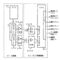
図6は、主基板31における回路構成の一例を示すブロック図である。なお、図6には、払出制御基板37、ランプ制御基板35、音声制御基板70、発射制御基板91および図柄制御基板80も示されている。主基板31には、プログラムに従ってパチンコ遊技機1を制御する基本回路53と、ゲートスイッチ12、始動口スイッチ17、Vカウントスイッチ22、カウントスイッチ23入賞口スイッチ19a,24a、満タンスイッチ48および賞球カウントスイッチ301Aからの信号を基本回路53に与えるスイッチ回路58と、可変入賞球装置15を開閉するソレノイド16および開閉板20を開閉するソレノイド21を基本回路53からの指令に従って駆動するソレノイド回路59とが搭載されている。
FIG. 6 is a block diagram illustrating an example of a circuit configuration in the
また、基本回路53から与えられるデータに従って、大当りの発生を示す大当り情報、可変表示部9の画像表示開始に利用された始動入賞球の個数を示す始動情報、確率変動が生じたことを示す確変情報等をホール管理コンピュータ等のホストコンピュータに対して出力する情報出力回路64を含む。
Further, according to the data given from the basic circuit 53, the jackpot information indicating the occurrence of the jackpot, the starting information indicating the number of starting winning balls used for starting the image display of the
基本回路53は、ゲーム制御用のプログラム等を記憶するROM54、ワークメモリとして使用される記憶手段の一例であるRAM55、制御用のプログラムに従って制御動作を行うCPU56およびI/Oポート部57を含む。この実施の形態では、ROM54,RAM55はCPU56に内蔵されている。すなわち、CPU56は、1チップマイクロコンピュータである。なお、1チップマイクロコンピュータは、少なくともRAM55が内蔵されていればよく、ROM54およびI/Oポート部57は外付けであっても内蔵されていてもよい。また、I/Oポート部57は、マイクロコンピュータにおける情報入出力可能な端子である。
The basic circuit 53 includes a ROM 54 that stores a game control program and the like, a
さらに、主基板31には、電源投入時に基本回路53をリセットするための初期リセット回路65と、基本回路53から与えられるアドレス信号をデコードしてI/Oポート部57のうちのいずれかのI/Oポートを選択するための信号を出力するアドレスデコード回路67とが設けられている。
なお、球払出装置97から主基板31に入力されるスイッチ情報もあるが、図6ではそれらは省略されている。
Further, the
Note that there is also switch information input to the
遊技球を打撃して発射する打球発射装置は発射制御基板91上の回路によって制御される駆動モータ94で駆動される。そして、駆動モータ94の駆動力は、操作ノブ5の操作量に従って調整される。すなわち、発射制御基板91上の回路によって、操作ノブ5の操作量に応じた速度で打球が発射されるように制御される。
A ball hitting device for hitting and launching a game ball is driven by a drive motor 94 controlled by a circuit on the
なお、この実施の形態では、ランプ制御基板35に搭載されているランプ制御手段が、遊技盤に設けられている始動記憶表示器18、ゲート通過記憶表示器41および装飾ランプ25の表示制御を行うとともに、枠側に設けられている遊技効果ランプ・LED28a,28b,28c、賞球ランプ51および球切れランプ52の表示制御を行う。ここで、ランプ制御手段は発光体制御手段の一例である。また、特別図柄を可変表示する可変表示部9および普通図柄を可変表示する可変表示器10の表示制御は、図柄制御基板80に搭載されている図柄制御手段(表示制御手段)によって行われる。
In this embodiment, the lamp control means mounted on the
装飾ランプ25および遊技効果ランプ・LED28a,28b,28cは、遊技の進行に伴って装飾的に様々に表示制御される。また、始動記憶表示器18およびゲート通過記憶表示器41は、保留個数を遊技者に報知するための発光体である。さらに、賞球ランプ51および球切れランプ52も、未賞球ありおよび球切れを遊技者や遊技店員に報知するための発光体である。この実施の形態では、遊技制御手段とは別に設けられているランプ制御手段が、装飾ランプ25および遊技効果ランプ・LED28a,28b,28cの表示制御を行い、さらに、情報報知のための設けられている始動記憶表示器18、ゲート通過記憶表示器41、賞球ランプ51および球切れランプ52の表示制御も行う。従って、遊技制御手段は、遊技機に設けられている発光体の具体的な点灯/消灯制御を行わなくてよく、遊技制御手段の発光体制御に関する制御負担が大きく低減されている。
The
図7は、図柄制御基板80内の回路構成を、可変表示部9の一実現例であるLCD(液晶表示装置)82、可変表示器10、主基板31の出力ポート(ポートA,B)571,572および出力バッファ回路63A,63Bとともに示すブロック図である。出力ポート571からは8ビットのデータが出力され、出力ポート572からは1ビットのストローブ信号(INT信号)が出力される。
FIG. 7 shows the circuit configuration in the
図柄制御用CPU101は、制御データROM102に格納されたプログラムに従って動作し、主基板31からノイズフィルタ107および入力バッファ回路105Bを介してINT信号が入力されると、入力バッファ回路105Aを介して図柄制御コマンドを受信する。入力バッファ回路105A,105Bとして、例えば汎用ICである74HC540,74HC14を使用することができる。なお、図柄制御用CPU101がI/Oポートを内蔵していない場合には、入力バッファ回路105A,105Bと図柄制御用CPU101との間に、I/Oポートが設けられる。
The symbol control CPU 101 operates according to a program stored in the
そして、図柄制御用CPU101は、受信した図柄制御コマンドに従って、LCD82に表示される画面の表示制御を行う。具体的には、図柄制御コマンドに応じた指令をVDP103に与える。VDP103は、キャラクタROM86から必要なデータを読み出す。VDP103は、入力したデータに従ってLCD82に表示するための画像データを生成し、R,G,B信号および同期信号をLCD82に出力する。
Then, the symbol control CPU 101 performs display control of the screen displayed on the
なお、図7には、VDP103をリセットするためのリセット回路83、VDP103に動作クロックを与えるための発振回路85、および使用頻度の高い画像データを格納するキャラクタROM86も示されている。キャラクタROM86に格納される使用頻度の高い画像データとは、例えば、LCD82に表示される人物、動物、または、文字、図形もしくは記号等からなる画像などである。
7 also shows a
入力バッファ回路105A,105Bは、主基板31から図柄制御基板80へ向かう方向にのみ信号を通過させることができる。従って、図柄制御基板80側から主基板31側に信号が伝わる余地はない。すなわち、入力バッファ回路105A,105Bは、入力ポートともに不可逆性情報入力手段を構成する。図柄制御基板80内の回路に不正改造が加えられても、不正改造によって出力される信号が主基板31側に伝わることはない。
The
なお、出力ポート571,572の出力をそのまま図柄制御基板80に出力してもよいが、単方向にのみ信号伝達可能な出力バッファ回路63A,63Bを設けることによって、主基板31から図柄制御基板80への一方向性の信号伝達をより確実にすることができる。すなわち、出力バッファ回路63A,63Bは、出力ポートともに不可逆性情報出力手段を構成する。
The outputs of the
また、高周波信号を遮断するノイズフィルタ107として、例えば3端子コンデンサやフェライトビーズが使用されるが、ノイズフィルタ107の存在によって、図柄制御コマンドに基板間でノイズが乗ったとしても、その影響は除去される。なお、主基板31のバッファ回路63A,63Bの出力側にもノイズフィルタを設けてもよい。
In addition, for example, a three-terminal capacitor or ferrite bead is used as the noise filter 107 that cuts off the high-frequency signal. However, even if noise is placed between the boards in the symbol control command due to the presence of the noise filter 107, the influence is removed. Is done. A noise filter may be provided also on the output side of the buffer circuits 63A and 63B of the
図8は、主基板31における音声制御コマンドの信号送信部分および音声制御基板70の構成例を示すブロック図である。この実施の形態では、遊技進行に応じて、遊技領域7の外側に設けられているスピーカ27の音声出力を指示するための音声制御コマンドが、主基板31から音声制御基板70に出力される。
FIG. 8 is a block diagram showing a configuration example of the voice control command signal transmission portion of the
図8に示すように、音声制御コマンドは、基本回路53におけるI/Oポート部57の出力ポート(出力ポートC,D)573,574から出力される。出力ポート573からは8ビットのデータが出力され、出力ポート574からは1ビットのINT信号が出力される。音声制御基板70において、主基板31からの各信号は、入力バッファ回路705,705Bを介して音声制御用CPU701に入力する。なお、音声制御用CPU701がI/Oポートを内蔵していない場合には、入力バッファ回路705A,705Bと音声制御用CPU701との間に、I/Oポートが設けられる。
As shown in FIG. 8, the voice control command is output from the output ports (output ports C and D) 573 and 574 of the I /
そして、例えばディジタルシグナルプロセッサによる音声合成回路702は、音声制御用CPU701の指示に応じた音声や効果音を発生し音量切替回路703に出力する。音量切替回路703は、音声制御用CPU701の出力レベルを、設定されている音量に応じたレベルにして音量増幅回路704に出力する。音量増幅回路704は、増幅した音声信号をスピーカ27に出力する。
Then, for example, a voice synthesis circuit 702 using a digital signal processor generates voice and sound effects according to instructions from the
入力バッファ回路705A,705Bとして、例えば、汎用のCMOS−ICである74HC540,74HC14が用いられる。入力バッファ回路705A,705Bは、主基板31から音声制御基板70へ向かう方向にのみ信号を通過させることができる。よって、音声制御基板70側から主基板31側に信号が伝わる余地はない。従って、音声制御基板70内の回路に不正改造が加えられても、不正改造によって出力される信号が主基板31側に伝わることはない。なお、入力バッファ回路705A,705Bの入力側にノイズフィルタを設けてもよい。
As the input buffer circuits 705A and 705B, for example, 74HC540 and 74HC14, which are general-purpose CMOS-ICs, are used. The input buffer circuits 705A and 705B can pass signals only in the direction from the
また、主基板31において、出力ポート573,574の外側にバッファ回路67A,67Bが設けられている。バッファ回路67A,67Bとして、例えば、汎用のCMOS−ICである74HC250,74HC14が用いられる。このような構成によれば、外部から主基板31の内部に入力される信号が阻止されるので、音声制御基板70から主基板31に信号が与えられる可能性がある信号ラインをさらに確実になくすことができる。なお、バッファ回路67A,67Bの出力側にノイズフィルタを設けてもよい。
In the
図9は、主基板31およびランプ制御基板35における信号送受信部分を示すブロック図である。この実施の形態では、遊技領域7の外側に設けられている遊技効果LED28a、遊技効果ランプ28b,28cと遊技盤に設けられている装飾ランプ25の点灯/消灯と、賞球ランプ51および球切れランプ52の点灯/消灯とを示すランプ制御コマンドが主基板31からランプ制御基板35に出力される。また、始動記憶表示器18およびゲート通過記憶表示器41の点灯個数を示すランプ制御コマンドも主基板31からランプ制御基板35に出力される。
FIG. 9 is a block diagram showing signal transmission / reception portions in the
図9に示すように、ランプ制御に関するランプ制御コマンドは、基本回路53におけるI/Oポート部57の出力ポート(出力ポートE,F)575,576から出力される。出力ポート575は8ビットのデータを出力し、出力ポート576は1ビットのINT信号を出力する。ランプ制御基板35において、主基板31からの制御コマンドは、入力バッファ回路355A,355Bを介してランプ制御用CPU351に入力する。なお、ランプ制御用CPU351がI/Oポートを内蔵していない場合には、入力バッファ回路355A,355Bとランプ制御用CPU351との間に、I/Oポートが設けられる。
As shown in FIG. 9, the lamp control command related to the lamp control is output from the output ports (output ports E and F) 575 and 576 of the I /
ランプ制御基板35において、ランプ制御用CPU351は、各制御コマンドに応じて定義されている遊技効果LED28a、遊技効果ランプ28b,28c、装飾ランプ25の点灯/消灯パターンに従って、遊技効果LED28a、遊技効果ランプ28b,28c、装飾ランプ25に対して点灯/消灯信号を出力する。点灯/消灯信号は、遊技効果LED28a、遊技効果ランプ28b,28c、装飾ランプ25に出力される。なお、点灯/消灯パターンは、ランプ制御用CPU351の内蔵ROMまたは外付けROMに記憶されている。
In the
主基板31において、CPU56は、RAM55の記憶内容に未払出の賞球残数があるときに賞球ランプ51の点灯を指示する制御コマンドを出力し、前述した遊技盤裏面の払出球通路186a,186bの上流に設置されている球切れスイッチ187a,187b(図4参照)が遊技球を検出しなくなると球切れランプ52の点灯を指示する制御コマンドを出力する。ランプ制御基板35において、各制御コマンドは、入力バッファ回路355A,355Bを介してランプ制御用CPU351に入力する。ランプ制御用CPU351は、それらの制御コマンドに応じて、賞球ランプ51および球切れランプ52を点灯/消灯する。なお、点灯/消灯パターンは、ランプ制御用CPU351の内蔵ROMまたは外付けROMに記憶されている。
In the
さらに、ランプ制御用CPU351は、制御コマンドに応じて始動記憶表示器18およびゲート通過記憶表示器41に対して点灯/消灯信号を出力する。
Further, the lamp control CPU 351 outputs a light on / off signal to the
入力バッファ回路355A,355Bとして、例えば、汎用のCMOS−ICである74HC540,74HC14が用いられる。入力バッファ回路355A,355Bは、主基板31からランプ制御基板35へ向かう方向にのみ信号を通過させることができる。従って、ランプ制御基板35側から主基板31側に信号が伝わる余地はない。たとえ、ランプ制御基板35内の回路に不正改造が加えられても、不正改造によって出力される信号がメイン基板31側に伝わることはない。なお、入力バッファ回路355A,355Bの入力側にノイズフィルタを設けてもよい。
As the
また、主基板31において、出力ポート575,576の外側にバッファ回路62A,62Bが設けられている。バッファ回路62A,62Bとして、例えば、汎用のCMOS−ICである74HC250,74HC14が用いられる。このような構成によれば、外部から主基板31の内部に入力される信号が阻止されるので、ランプ制御基板70から主基板31に信号が与えられる可能性がある信号ラインをさらに確実になくすことができる。なお、バッファ回路62A,62Bの出力側にノイズフィルタを設けてもよい。
In the
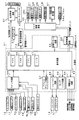
図10は、払出制御基板37および球払出装置97の構成要素などの賞球に関連する構成要素を示すブロック図である。図10に示すように、満タンスイッチ48からの検出信号は、中継基板71を介して主基板31のI/Oポート57に入力される。満タンスイッチ48は、余剰玉受皿4の満タンを検出するスイッチである。
FIG. 10 is a block diagram showing components related to the prize ball, such as components of the
球切れスイッチ187(187a,187b)からの検出信号は、中継基板72および中継基板71を介して主基板31のI/Oポート57に入力される。球切れスイッチ187は、払出球通路内の遊技球の有無を検出するスイッチである。
A detection signal from the ball break switch 187 (187a, 187b) is input to the I /
入賞があると、払出制御基板37には、主基板31から賞球個数を示す払出制御コマンドが入力される。賞球個数を示す払出制御コマンドは、入力バッファ回路373Aを介してI/Oポート372aに入力される。また、INT信号が入力バッファ回路373Bを介してCPUの割込端子に入力される。入力バッファ回路373A,373Bにおける各バッファは、主基板31から払出制御基板37へ向かう方向にのみ信号を通過させることができる。従って、払出制御基板37側から主基板31側に信号が伝わる余地はない。払出制御基板37内の回路に不正改造が加えられても、不正改造によって出力される信号が主基板31側に伝わることはない。また、主基板31において、払出制御コマンドを出力する出力ポート577A,577Bの外側にバッファ回路68A,68Bが設けられている。このような構成によれば、外部から主基板31の内部に入力される信号が阻止されるので、払出制御基板37から主基板31に信号が与えられる可能性がある信号ラインをより確実になくすことができる。
When there is a win, a payout control command indicating the number of winning balls is input from the
主基板31のCPU56は、球切れスイッチ187からの検出信号が球切れ状態を示しているか、または、満タンスイッチ48からの検出信号が満タン状態を示していると、球払出禁止を指示する払出制御コマンドを送出する。球払出禁止を指示する払出制御コマンドを受信すると、払出制御基板37の払出制御用CPU371は、球払出処理を停止する。
The CPU 56 of the
さらに、賞球カウントスイッチ301Aからの検出信号も、中継基板72および中継基板71を介して主基板31のI/Oポート57に入力される。また、賞球カウントスイッチ301Aおよび球貸しカウントスイッチ301Bは、球払出装置97の払出機構部分に設けられ、実際に払い出された遊技球を検出する。
Further, a detection signal from the prize ball count switch 301 </ b> A is also input to the I /
入賞があると、払出制御基板37には、主基板31の出力ポート(ポートG,H)577A,577Bから賞球個数を示す払出制御コマンドが入力される。出力ポート577は8ビットのデータを出力し、出力ポート578は1ビットのストローブ信号(INT信号)を出力する。賞球個数を示す払出制御コマンドは、入力バッファ回路373を介してI/Oポート372aに入力される。払出制御用CPU371は、I/Oポート372aを介して払出制御コマンドを入力し、払出制御コマンドに応じて球払出装置97を駆動して賞球払出を行う。なお、この実施の形態では、払出制御用CPU371は、1チップマイクロコンピュータであり、少なくともRAMが内蔵されている。
When there is a win, a payout control command indicating the number of winning balls is input to the
払出制御用CPU371は、出力ポート372gを介して、貸し玉数を示す球貸し個数信号をターミナル基板160に出力し、ブザー駆動信号をブザー基板75に出力する。ブザー基板75にはブザーが搭載されている。さらに、出力ポート372eを介して、エラー表示用LED374にエラー信号を出力する。
The
さらに、払出制御基板37の入力ポート372bには、中継基板72を介して、賞球カウントスイッチ301Aの検出信号の検出信号が入力される。払出制御基板37からの払出モータ289への駆動信号は、出力ポート372cおよび中継基板72を介して球払出装置97の賞球機構部分における払出モータ289に伝えられる。また、払出制御基板37から振分用ソレノイド310への駆動信号は、出力ポート372dおよび中継基板72を介して球払出装置97の振分用ソレノイド310に伝えられる。
Further, the detection signal of the detection signal of the prize ball count switch 301 </ b> A is input to the
カードユニット50には、カードユニット制御用マイクロコンピュータが搭載されている。また、カードユニット50には、端数表示スイッチ152、連結台方向表示器153、カード投入表示ランプ154およびカード挿入口155が設けられている(図1参照)。残高表示基板74には、打球供給皿3の近傍に設けられている度数表示LED、球貸しスイッチおよび返却スイッチが接続される。
The
残高表示基板74からカードユニット50には、遊技者の操作に応じて、球貸しスイッチ信号および返却スイッチ信号が払出制御基板37を介して与えられる。また、カードユニット50から残高表示基板74には、プリペイドカードの残高を示すカード残高表示信号および球貸し可表示信号が払出制御基板37を介して与えられる。カードユニット50と払出制御基板37の間では、ユニット操作信号(BRDY信号)、球貸し要求信号(BRQ信号)、球貸し完了信号(EXS信号)およびパチンコ機動作信号(PRDY信号)がI/Oポート372fを介してやりとりされる。
A ball lending switch signal and a return switch signal are given from the
パチンコ遊技機1の電源が投入されると、払出制御基板37の払出制御用CPU371は、カードユニット50にPRDY信号を出力する。カードユニット50においてカードが受け付けられ、球貸しスイッチが操作され球貸しスイッチ信号が入力されると、カードユニット制御用マイクロコンピュータは、払出制御基板37にBRDY信号を出力する。この時点から所定の遅延時間が経過すると、カードユニット制御用マイクロコンピュータは、払出制御基板37にBRQ信号を出力する。そして、払出制御基板37の払出制御用CPU371は、BRQ信号に応じてEXS信号をオンするとともに、払出モータ289を駆動し、所定個の貸し玉を遊技者に払い出す。そして、払出が完了したら、払出制御用CPU371は、カードユニット50にEXS信号をオフ状態にする。
When the power of the
以上のように、カードユニット50からの信号は全て払出制御基板37に入力される構成になっている。従って、球貸し制御に関して、カードユニット50から主基板31に信号が入力されることはなく、主基板31の基本回路53にカードユニット50の側から不正に信号が入力される余地はない。なお、主基板31および払出制御基板37には、ソレノイドおよびモータやランプを駆動するためのドライバ回路が搭載されているが、図10では、それらの回路は省略されている。
As described above, all signals from the
この実施の形態では、主基板31および払出制御基板37におけるRAMは、バックアップ電源でバックアップされている。すなわち、遊技機に対する電力供給が停止しても、所定期間はRAMの内容が保存される。そして、各CPUは、電源電圧の低下を検出すると、所定の処理を行った後に電源復旧待ちの状態になる。また、電源投入時に、各CPUは、RAMにデータが保存されている場合には、保存データにもとづいて電源断前の状態を復元する。また、図10に示された各入力ポートは、払出制御用CPU371に内蔵されていてもよい。
In this embodiment, the RAM in the
図11は、電源監視および電源バックアップのための主基板31のCPU56周りの一構成例を示すブロック図である。図11に示すように、第1の電源監視回路(第1の電源監視手段)からの電圧低下信号が、CPU56のマスク不能割込端子(NMI端子)に接続されている。第1の電源監視回路は、遊技機が使用する各種直流電源のうちのいずれかの電源の電圧を監視して電源電圧低下を検出する回路である。この実施の形態では、VSLの電源電圧を監視して電圧値が所定値以下になるとローレベルの電圧低下信号を発生する。VSLは、遊技機で使用される直流電圧のうちで最大のものであり、この例では+30Vである。従って、CPU56は、割込処理によって電源断の発生を確認することができる。なお、この実施の形態では、第1の電源監視回路は、後述する電源基板に搭載されている。
FIG. 11 is a block diagram showing a configuration example around the CPU 56 of the
図11には、初期リセット回路65も示されているが、この実施の形態では、初期リセット回路65は、第2の電源監視回路(第2の電源監視手段)も兼ねている。すなわち、リセットIC651は、電源投入時に、外付けのコンデンサの容量で決まる所定時間だけ出力をローレベルとし、所定時間が経過すると出力をハイレベルにする。すなわち、リセット信号をハイレベルに立ち上げてCPU56を動作可能状態にする。また、リセットIC651は、第1の電源監視回路が監視する電源電圧と等しい電源電圧であるVSLの電源電圧を監視して電圧値が所定値(第1の電源監視回路が電圧低下信号を出力する電源電圧値よりも低い値)以下になるとローレベルの電圧低下信号を発生する。従って、CPU56は、第1の電源監視回路からの電圧低下信号に応じて所定の電力供給停止時処理を行った後、システムリセットされる。なお、この実施の形態では、リセット信号と第2の電源監視回路からの電圧低下信号とは同一の信号である。 Although the initial reset circuit 65 is also shown in FIG. 11, in this embodiment, the initial reset circuit 65 also serves as a second power supply monitoring circuit (second power supply monitoring means). That is, when the power is turned on, the reset IC 651 sets the output to the low level for a predetermined time determined by the capacity of the external capacitor, and sets the output to the high level when the predetermined time elapses. That is, the reset signal is raised to a high level to make the CPU 56 operable. The reset IC 651 monitors the power supply voltage of VSL, which is the power supply voltage equal to the power supply voltage monitored by the first power supply monitoring circuit, and the voltage value is a predetermined value (the first power supply monitoring circuit outputs a voltage drop signal). When the voltage is lower than the power supply voltage value), a low level voltage drop signal is generated. Therefore, the CPU 56 performs a predetermined power supply stop process in response to the voltage drop signal from the first power supply monitoring circuit, and then the system is reset. In this embodiment, the reset signal and the voltage drop signal from the second power supply monitoring circuit are the same signal.
図11に示すように、リセットIC651からのリセット信号は、NAND回路947に入力されるとともに、反転回路(NOT回路)944を介してカウンタIC941のクリア端子に入力される。カウンタIC941は、クリア端子への入力がローレベルになると、発振器943からのクロック信号をカウントする。そして、カウンタIC941のQ5出力がNOT回路945,946を介してNAND回路947に入力される。また、カウンタIC941のQ6出力は、フリップフロップ(FF)942のクロック端子に入力される。フリップフロップ942のD入力はハイレベルに固定され、Q出力は論理和回路(OR回路)949に入力される。OR回路949の他方の入力には、NAND回路947の出力がNOT回路948を介して導入される。そして、OR回路949の出力がCPU56のリセット端子に接続されている。このような構成によれば、電源投入時に、CPU56のリセット端子に2回のリセット信号(ローレベル信号)が与えられるので、CPU56は、確実に動作を開始する。
As shown in FIG. 11, the reset signal from the reset IC 651 is input to the
そして、例えば、第1の電源監視回路の検出電圧(電圧低下信号を出力することになる電圧)を+22Vとし、第2の電源監視回路の検出電圧を+9Vとする。そのように構成した場合には、第1の電源監視回路と第2の電源監視回路とは、同一の電源VSLの電圧を監視するので、第1の電圧監視回路が電圧低下信号を出力するタイミングと第2の電圧監視回路が電圧低下信号を出力するタイミングの差を所望の所定期間に確実に設定することができる。所望の所定期間とは、第1の電源監視回路からの電圧低下信号に応じて電力供給停止時処理を開始してから電力供給停止時処理が確実に完了するまでの期間である。 For example, the detection voltage of the first power supply monitoring circuit (voltage that outputs a voltage drop signal) is + 22V, and the detection voltage of the second power supply monitoring circuit is + 9V. In such a configuration, since the first power monitoring circuit and the second power monitoring circuit monitor the voltage of the same power supply VSL, the timing when the first voltage monitoring circuit outputs the voltage drop signal. And the timing at which the second voltage monitoring circuit outputs the voltage drop signal can be reliably set to a desired predetermined period. The desired predetermined period is a period from when the power supply stop process is started in response to the voltage drop signal from the first power supply monitoring circuit until the power supply stop process is reliably completed.
この例では、第1の電源監視手段が検出信号を出力することになる第1検出条件は+30V電源電圧が+22Vにまで低下したことであり、第2の電源監視手段が検出信号を出力することになる第2検出条件は+30V電源電圧が+9Vにまで低下したことになる。ただし、ここで用いられている電圧値は一例であって、他の値を用いてもよい。 In this example, the first detection condition for the first power supply monitoring means to output the detection signal is that the + 30V power supply voltage has dropped to + 22V, and the second power supply monitoring means outputs the detection signal. The second detection condition that becomes is that the + 30V power supply voltage is lowered to + 9V. However, the voltage value used here is an example, and other values may be used.
ただし、監視範囲が狭まるが、第1の電圧監視回路および第2の電圧監視回路の監視電圧として+5V電源電圧を用いることも可能である。その場合にも、第1の電圧監視回路の検出電圧は、第2の電圧監視回路の検出電圧よりも高く設定される。 However, although the monitoring range is narrowed, it is also possible to use a + 5V power supply voltage as the monitoring voltage of the first voltage monitoring circuit and the second voltage monitoring circuit. Also in that case, the detection voltage of the first voltage monitoring circuit is set higher than the detection voltage of the second voltage monitoring circuit.
CPU56等の駆動電源である+5V電源から電力が供給されていない間、RAMの少なくとも一部は、電源基板から供給されるバックアップ電源によってバックアップされ、遊技機に対する電源が断しても内容は保存される。そして、+5V電源が復旧すると、初期リセット回路65からリセット信号が発せられるので、CPU56は、通常の動作状態に復帰する。そのとき、必要なデータがバックアップされているので、停電等からの復旧時には停電発生時の遊技状態に復帰することができる。 While power is not supplied from the + 5V power source that is the driving power source of the CPU 56 or the like, at least a part of the RAM is backed up by the backup power source supplied from the power supply board, and the contents are preserved even if the power to the gaming machine is cut off. The When the + 5V power supply is restored, a reset signal is issued from the initial reset circuit 65, so that the CPU 56 returns to a normal operation state. At that time, since necessary data is backed up, it is possible to return to the gaming state at the time of the power failure when recovering from the power failure.
なお、図11では、電源投入時にCPU56のリセット端子に2回のリセット信号(ローレベル信号)が与えられる構成が示されたが、リセット信号の立ち上がりタイミングが1回しかなくても確実にリセット解除されるCPUを使用する場合には、符号941〜949で示された回路素子は不要である。その場合、リセットIC651の出力がそのままCPU56のリセット端子に接続される。 11 shows a configuration in which a reset signal (low level signal) is given twice to the reset terminal of the CPU 56 when the power is turned on. However, even if the rising timing of the reset signal is only once, the reset is surely released. When using the CPU to be used, the circuit elements denoted by reference numerals 941 to 949 are not necessary. In that case, the output of the reset IC 651 is directly connected to the reset terminal of the CPU 56.
図12は、遊技機の電源基板910の一構成例を示すブロック図である。電源基板910は、主基板31、図柄制御基板80、音声制御基板70、ランプ制御基板35および払出制御基板37等の電気部品制御基板と独立して設置され、遊技機内の各電気部品制御基板および機構部品が使用する電圧を生成する。この例では、AC24V、VSL(DC+30V)、DC+21V、DC+12VおよびDC+5Vを生成する。また、バックアップ電源となるコンデンサ916は、DC+5Vすなわち各基板上のIC等を駆動する電源のラインから充電される。
FIG. 12 is a block diagram illustrating a configuration example of the
トランス911は、交流電源からの交流電圧を24Vに変換する。AC24V電圧は、コネクタ915に出力される。また、整流回路912は、AC24Vから+30Vの直流電圧を生成し、DC−DCコンバータ913およびコネクタ915に出力する。DC−DCコンバータ913は、+22V、+12Vおよび+5Vを生成してコネクタ915に出力する。コネクタ915は例えば中継基板に接続され、中継基板から各電気部品制御基板および機構部品に必要な電圧の電力が供給される。
The transformer 911 converts AC voltage from the AC power source into 24V. The AC 24V voltage is output to the
DC−DCコンバータ913からの+5Vラインは分岐してバックアップ+5Vラインを形成する。バックアップ+5Vラインとグラウンドレベルとの間には大容量のコンデンサ916が接続されている。コンデンサ916は、遊技機に対する電力供給が遮断されたときの電気部品制御基板のバックアップRAM(電源バックアップされているRAMすなわち記憶内容保持状態となりうる記憶手段)に対して記憶状態を保持できるように電力を供給するバックアップ電源となる。また、+5Vラインとバックアップ+5Vラインとの間に、逆流防止用のダイオード917が挿入される。
The + 5V line from the DC-DC converter 913 branches to form a backup + 5V line. A large-
なお、バックアップ電源として、+5V電源から充電可能な電池を用いてもよい。電池を用いる場合には、+5V電源から電力供給されない状態が所定時間継続すると容量がなくなるような充電池が用いられる。 A battery that can be charged from a + 5V power supply may be used as the backup power supply. In the case of using a battery, a rechargeable battery is used in which the capacity disappears when a state in which no power is supplied from the +5 V power source continues for a predetermined time.
また、電源基板910には、上述した第1の電源監視回路を構成する電源監視用IC902が搭載されている。電源監視用IC902は、VSL電源電圧を導入し、VSL電源電圧を監視することによって電源断の発生を検出する。具体的には、VSL電源電圧が所定値(この例では+22V)以下になったら、電源断が生ずるとして電圧低下信号を出力する。なお、監視対象の電源電圧は、各電気部品制御基板に搭載されている回路素子の電源電圧(この例では+5V)よりも高い電圧であることが好ましい。この例では、交流から直流に変換された直後の電圧であるVSLが用いられている。電源監視用IC902からの電圧低下信号は、主基板31や払出制御基板37等に供給される。
The
電源監視用IC902が電源断を検知するための所定値は、通常時の電圧より低いが、各電気部品制御基板上のCPUが暫くの間動作しうる程度の電圧である。また、電源監視用IC902が、CPU等の回路素子を駆動するための電圧(この例では+5V)よりも高く、また、交流から直流に変換された直後の電圧を監視するように構成されているので、CPUが必要とする電圧に対して監視範囲を広げることができる。従って、より精密な監視を行うことができる。さらに、監視電圧としてVSL(+30V)を用いる場合には、遊技機の各種スイッチに供給される電圧が+12Vであることから、電源瞬断時のスイッチオン誤検出の防止も期待できる。すなわち、+30V電源の電圧を監視すると、+30V作成の以降に作られる+12Vが落ち始める以前の段階でそれの低下を検出できる。よって、+12V電源の電圧が低下するとスイッチ出力がオン状態を呈するようになるが、+12Vより早く低下する+30V電源電圧を監視して電源断を認識すれば、スイッチ出力がオン状態を呈する前に電源復旧待ちの状態に入ってスイッチ出力を検出しない状態となることができる。
The predetermined value for the
また、電源監視用IC902は、電気部品制御基板とは別個の電源基板910に搭載されているので、第1の電源監視回路から複数の電気部品制御基板に電圧低下信号を供給することができる。電圧低下信号を必要とする電気部品制御基板が幾つあっても第1の電源監視手段は1つ設けられていればよいので、各電気部品制御基板における各電気部品制御手段が後述する復帰制御を行っても、遊技機のコストはさほど上昇しない。
Further, since the
なお、図12に示された構成では、電源監視用IC902の検出出力(電圧低下信号)は、バッファ回路918,919を介してそれぞれの電気部品制御基板(例えば主基板31と払出制御基板37)に伝達されるが、例えば、1つの検出出力を中継基板に伝達し、中継基板から各電気部品制御基板に同じ信号を分配する構成でもよい。また、電圧低下信号を必要とする基板数に応じたバッファ回路を設けてもよい。
In the configuration shown in FIG. 12, the detection output (voltage drop signal) of the
次に遊技機の動作について説明する。
図13は、主基板31におけるCPU56が実行するメイン処理を示すフローチャートである。遊技機に対する電源が投入されると、メイン処理において、CPU56は、まず、停電からの復旧時であったか否か確認する(ステップS1)。停電からの復旧時であったか否かは、例えば、電源断時にバックアップRAM領域に設定される電源断フラグによって確認される。
Next, the operation of the gaming machine will be described.
FIG. 13 is a flowchart showing main processing executed by the CPU 56 on the
停電からの復旧時であった場合には、バックアップRAM領域のデータチェック(この例ではパリティチェック)を行う(ステップS3)。不測の電源断が生じた後に復旧した場合には、バックアップRAM領域のデータは保存されていたはずであるから、チェック結果は正常になる。チェック結果が正常でない場合には、内部状態を電源断時の状態に戻すことができないので、停電復旧時でない電源投入時に実行される初期化処理を実行する(ステップS4,S2)。 If it is time to recover from a power failure, a data check (parity check in this example) of the backup RAM area is performed (step S3). In the case of recovery after an unexpected power failure, the data in the backup RAM area should have been saved, so the check result is normal. If the check result is not normal, the internal state cannot be returned to the state when the power is cut off, and therefore an initialization process that is executed when the power is turned on not when the power failure is restored is executed (steps S4 and S2).
チェック結果が正常であれば、CPU56は、内部状態を電源断時の状態に戻すための遊技状態復旧処理を行うとともに(ステップS5)、電源断フラグをクリアする(ステップS6)。そして、バックアップRAM領域に保存されていたプログラムカウンタ(電源断時の実行アドレスが設定されている)の指すアドレスに復帰する。 If the check result is normal, the CPU 56 performs a game state recovery process for returning the internal state to the state at the time of power-off (step S5) and clears the power-off flag (step S6). Then, it returns to the address indicated by the program counter stored in the backup RAM area (the execution address when the power is turned off is set).
停電からの復旧時でない場合には、CPU56は、通常の初期化処理を実行する(ステップS1,S2)。その後、メイン処理では、タイマ割込フラグの監視(ステップS6)の確認が行われるループ処理に移行する。なお、ループ内では、表示用乱数更新処理(ステップS7)も実行される。 If it is not time to recover from a power failure, the CPU 56 executes normal initialization processing (steps S1 and S2). Thereafter, in the main process, the process proceeds to a loop process in which the monitoring of the timer interrupt flag (step S6) is confirmed. In the loop, display random number update processing (step S7) is also executed.
なお、ここでは、ステップS1で停電からの復旧か否かを確認し、停電からの復旧時であればパリティチェックを行ったが、最初に、パリティチェックを実行し、チェック結果が正常でなければ停電からの復旧ではないと判断してステップS2の初期化処理を実行し、チェック結果が正常であれば遊技状態復帰処理を行ってもよい。すなわち、パリティチェックの結果をもって停電からの復旧であるか否かを判断してもよい。 Here, it is confirmed in step S1 whether or not the recovery from the power failure, and if the recovery from the power failure, the parity check is performed. First, the parity check is performed and the check result is not normal. If it is determined that the power is not recovered from the power failure, the initialization process of step S2 is executed. If the check result is normal, the game state return process may be performed. That is, it may be determined whether or not recovery from a power failure is made based on the result of the parity check.
また、停電復旧処理を実行するか否か判断する場合に、すなわち、遊技状態を復旧するか否か判断する際に、保存されていたRAMデータにおける特別プロセスフラグ等や始動入賞記憶数データによって、遊技機が遊技待機状態(図柄変動中でなく、大当り遊技中でなく、確変中でなく、また、始動入賞記憶がない状態)であることが確認されたら、遊技状態復旧処理を行わずに初期化処理を実行するようにしてもよい。 Further, when determining whether or not to execute the power failure recovery processing, that is, when determining whether or not to restore the gaming state, according to the special process flag or the like in the stored RAM data or the start winning memory number data, If it is confirmed that the gaming machine is in a game standby state (not changing in design, not in big hit game, not in probable change, and no start winning memory), it is initial without performing game state recovery processing. The process may be executed.
通常の初期化処理では、図14に示すように、レジスタおよびRAMのクリア処理(ステップS2a)と、必要な初期値設定処理(ステップS2b)が行われた後に、2ms毎に定期的にタイマ割込がかかるようにCPU56に設けられているタイマレジスタの初期設定(タイムアウトが2msであることと繰り返しタイマが動作する設定)が行われる(ステップS2c)。すなわち、ステップS2cで、タイマ割込を能動化する処理と、タイマ割込インタバルを設定する処理とが実行される。 In normal initialization processing, as shown in FIG. 14, after timer and register clear processing (step S2a) and necessary initial value setting processing (step S2b) are performed, a timer allocation is periodically performed every 2 ms. Initial setting of the timer register provided in the CPU 56 (setting that the time-out is 2 ms and the timer repeatedly operates) is performed so as to cause a delay (step S2c). That is, in step S2c, processing for activating a timer interrupt and processing for setting a timer interrupt interval are executed.
従って、この実施の形態では、CPU56の内部タイマが繰り返しタイマ割込を発生するように設定される。この実施の形態では、繰り返し周期は2msに設定される。そして、図15に示すように、タイマ割込が発生すると、CPU56は、タイマ割込フラグをセットする(ステップS11)。 Therefore, in this embodiment, the internal timer of the CPU 56 is set to repeatedly generate a timer interrupt. In this embodiment, the repetition period is set to 2 ms. Then, as shown in FIG. 15, when a timer interrupt occurs, the CPU 56 sets a timer interrupt flag (step S11).
CPU56は、ステップS8において、タイマ割込フラグがセットされたことを検出すると、タイマ割込フラグをリセットするとともに(ステップS9)、遊技制御処理を実行する(ステップS10)。以上の制御によって、この実施の形態では、遊技制御処理は2ms毎に起動されることになる。なお、この実施の形態では、タイマ割込処理ではフラグセットのみがなされ、遊技制御処理はメイン処理において実行されるが、タイマ割込処理で遊技制御処理を実行してもよい。 When detecting that the timer interrupt flag is set in step S8, the CPU 56 resets the timer interrupt flag (step S9) and executes a game control process (step S10). With the above control, in this embodiment, the game control process is started every 2 ms. In this embodiment, only the flag is set in the timer interrupt process, and the game control process is executed in the main process, but the game control process may be executed in the timer interrupt process.
図16は、ステップS10の遊技制御処理を示すフローチャートである。遊技制御処理において、CPU56は、まず、格納領域に設定されたデータを出力ポートに出力する処理を行う(データ出力処理:ステップS21)。次いで、各出力ポートに出力される各種出力データを格納領域に設定する処理を行うとともに、ホール管理用コンピュータに出力される大当り情報、始動情報、確率変動情報などの出力データを格納領域に設定する出力データ設定処理を行う(ステップS22)。さらに、パチンコ遊技機1の内部に備えられている自己診断機能によって種々の異常診断処理が行われ、その結果に応じて必要ならば警報が発せられる(エラー処理:ステップS23)。
FIG. 16 is a flowchart showing the game control process of step S10. In the game control process, the CPU 56 first performs a process of outputting the data set in the storage area to the output port (data output process: step S21). Next, various output data output to each output port is set in the storage area, and output data such as jackpot information, start information, probability variation information output to the hall management computer is set in the storage area. An output data setting process is performed (step S22). Further, various abnormality diagnosis processes are performed by the self-diagnosis function provided in the
次に、遊技制御に用いられる大当り判定用の乱数等の各判定用乱数を示す各カウンタを更新する処理を行う(ステップS24)。 Next, a process of updating each counter indicating each determination random number such as a big hit determination random number used for game control is performed (step S24).
さらに、CPU56は、特別図柄プロセス処理を行う(ステップS25)。特別図柄プロセス制御では、遊技状態に応じてパチンコ遊技機1を所定の順序で制御するための特別図柄プロセスフラグに従って該当する処理が選び出されて実行される。そして、特別図柄プロセスフラグの値は、遊技状態に応じて各処理中に更新される。また、普通図柄プロセス処理を行う(ステップS26)。普通図柄プロセス処理では、7セグメントLEDによる可変表示器10を所定の順序で制御するための普通図柄プロセスフラグに従って該当する処理が選び出されて実行される。そして、普通図柄プロセスフラグの値は、遊技状態に応じて各処理中に更新される。
Further, the CPU 56 performs special symbol process processing (step S25). In the special symbol process control, corresponding processing is selected and executed according to a special symbol process flag for controlling the
さらに、CPU56は、スイッチ回路58を介して、ゲートセンサ12、始動口センサ17、カウントセンサ23および入賞口スイッチ19a,24aの状態を入力し、各入賞口や入賞装置に対する入賞があったか否か判定する(スイッチ処理:ステップS27)。CPU56は、さらに、停止図柄の種類を決定する乱数等の表示用乱数を更新する処理を行う(ステップS28)。
Further, the CPU 56 inputs the states of the
また、CPU56は、払出制御基板37との間の信号処理を行う(ステップS29)。すなわち、所定の条件が成立すると払出制御基板37に払出制御コマンドを出力するための処理を行う。払出制御基板37に搭載されている払出制御用CPUは、払出制御コマンドに応じて球払出装置97を駆動する。
Further, the CPU 56 performs signal processing with the payout control board 37 (step S29). That is, when a predetermined condition is satisfied, a process for outputting a payout control command to the
以上のように、メイン処理には遊技制御処理に移行すべきか否かを判定する処理が含まれ、CPU56の内部タイマが定期的に発生するタイマ割込にもとづくタイマ割込処理で遊技制御処理に移行すべきか否かを判定するためのフラグがセットされるので、遊技制御処理の全てが確実に実行される。つまり、遊技制御処理の全てが実行されるまでは、次回の遊技制御処理に移行すべきか否かの判定が行われないので、遊技制御処理中の全ての各処理が実行完了することは保証されている。 As described above, the main process includes a process for determining whether or not to shift to the game control process, and the timer control process based on the timer interrupt periodically generated by the internal timer of the CPU 56 is used for the game control process. Since a flag for determining whether or not to shift is set, all the game control processes are executed reliably. In other words, until all the game control processes are executed, it is not determined whether or not to shift to the next game control process, so it is guaranteed that all the processes in the game control process are completed. ing.
従来の一般的な遊技制御処理は、定期的に発生する外部割込によって、強制的に最初の状態に戻されていた。図16に示された例に則して説明すると、例えば、ステップS31の処理中であっても、強制的にステップS21の処理に戻されていた。つまり、遊技制御処理中の全ての各処理が実行完了する前に、次回の遊技制御処理が開始されてしまう可能性があった。 Conventional general game control processing is forcibly returned to the initial state by an external interrupt that occurs periodically. If it demonstrates in accordance with the example shown by FIG. 16, for example, even during the process of step S31, it was forcibly returned to the process of step S21. In other words, there is a possibility that the next game control process will be started before all the processes in the game control process are completed.
なお、ここでは、主基板31のCPU56が実行する遊技制御処理は、CPU56の内部タイマが定期的に発生するタイマ割込にもとづくタイマ割込処理でセットされるフラグに応じて実行されたが、定期的に(例えば2ms毎)信号を発生するハードウェア回路を設け、その回路からの信号をCPU56の外部割込端子に導入し、割込信号によって遊技制御処理に移行すべきか否かを判定するためのフラグをセットするようにしてもよい。
Here, the game control process executed by the CPU 56 of the
そのように構成した場合にも、遊技制御処理の全てが実行されるまでは、フラグの判定が行われないので、遊技制御処理中の全ての各処理が実行完了することが保証される。 Even in such a configuration, the determination of the flag is not performed until all of the game control processes are executed, so that it is guaranteed that all the processes in the game control process are completed.
図17は、可変表示器10において可変表示される普通図柄の変動の様子と当り動作(この例では可変入賞球装置15の開閉)の関係を示すタイミング図である。図17に示すように、普通図柄の変動開始時に、主基板31から図柄制御基板80に変動パターンおよび停止図柄を示すコマンドが送信される。また、変動停止時に、普通図柄停止を示すコマンドが送信される。
FIG. 17 is a timing chart showing the relationship between the variation of the normal symbol variably displayed on the
図18は、遊技の進行状況と可変表示部9において可変表示される特別図柄の変動等の関係を示すタイミング図である。図18に示すように、遊技の進行状況は、(1)電源投入時、(2)客待ちデモンストレーション中、(3)特別図柄の変動から確定まで、(4)特別図柄の確定から初回の大入賞口開放まで、(5)初回の大入賞口開放から最終回の大入賞口閉鎖まで、(6)最終回の大入賞口閉鎖から次の特別図柄の変動までに大別される((数字)は図における丸付数字と同義)。
FIG. 18 is a timing chart showing the relationship between the progress of the game and the variation of the special symbol variably displayed on the
図19は、特別図柄の変動と図柄制御コマンドとの関係を示すタイミング図である。図19に示すように、変動開始時に、変動パターン指定、左図柄指定、中図柄指定および右図柄指定のコマンドが主基板31から図柄制御基板80に送信される。また、変動終了時に、全図柄停止を示すコマンドが送信される。このように、この実施の形態では、1回の変動について5個のコマンドが送信される。
FIG. 19 is a timing chart showing the relationship between changes in special symbols and symbol control commands. As shown in FIG. 19, at the start of variation, commands for designating a variation pattern, designation of left symbol, designation of middle symbol, and designation of right symbol are transmitted from the
図20は、図柄制御コマンドのコマンド形態の一例を示す説明図である。この実施の形態では、図柄制御コマンドは2バイト構成であり、1バイト目はMODE(コマンドの分類)を表し、2バイト目はEXT(コマンドの種類)を表す。 FIG. 20 is an explanatory diagram showing an example of a command form of the symbol control command. In this embodiment, the symbol control command has a 2-byte structure, and the first byte represents MODE (command classification), and the second byte represents EXT (command type).
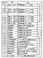
図21は、図柄制御コマンドの内容の一例を示す説明図である。図21に示された例において、コマンド8000(H)〜8022(H)、8100(H)〜8122(H)は、特別図柄を可変表示する可変表示部9における特別図柄の変動パターンを指定する図柄制御コマンドである。なお、変動パターンを指定するコマンドは変動開始指示も兼ねている。コマンド88XX(X=4ビットの任意の値)は、可変表示器10で可変表示される普通図柄の変動パターンに関する図柄制御コマンドである。コマンド89XXは、普通図柄の停止図柄を指定する図柄制御コマンドである。コマンド8AXX(X=4ビットの任意の値)は、普通図柄の可変表示の停止を指示する図柄制御コマンドである。
FIG. 21 is an explanatory diagram showing an example of the contents of the symbol control command. In the example shown in FIG. 21, commands 8000 (H) to 8022 (H) and 8100 (H) to 8122 (H) designate a variation pattern of a special symbol in the
コマンド91XX、92XXおよび93XXは、特別図柄の左中右の停止図柄を指定する図柄制御コマンドである。また、コマンドA0XXは、特別図柄の可変表示の停止を指示する図柄制御コマンドである。コマンドBXXXは、大当り遊技開始から大当り遊技終了までの間に送出される図柄制御コマンドである。そして、コマンドC000およびEXXXは、特別図柄の変動および大当り遊技に関わらない可変表示部9の表示状態に関する図柄制御コマンドである。なお、図21に示された(1)〜(6)は、図18に示された期間に対応している。図柄制御基板80の図柄制御手段は、主基板31の遊技制御手段から上述した図柄制御コマンドを受信すると図21に示された内容に応じて可変表示部9および可変表示器10の表示状態を変更する。
Commands 91XX, 92XX, and 93XX are symbol control commands for designating a stop symbol in the middle left of the special symbol. Command A0XX is a symbol control command for instructing stop of variable symbol special display. The command BXXX is a symbol control command that is sent between the start of the big hit game and the end of the big hit game. The commands C000 and EXXX are symbol control commands relating to the display state of the
図22は、図柄制御コマンドの送出形態の一例を示すタイミング図である。この実施の形態では、8ビットの図柄制御信号CD〜CD7によって図柄制御コマンドが出力される。そして、図柄制御コマンドの1バイト目および2バイト目が出力されているときに、INT信号がオン(この例ではローレベル)になる。INT信号のオン期間は例えば1μs以上であり、1バイト目と2バイト目との間には4μs以上の期間があけられる。図柄制御手段は、INT信号に応じた割込処理によって図柄制御信号CD〜CD7を入力する。 FIG. 22 is a timing chart showing an example of a form of sending a symbol control command. In this embodiment, a symbol control command is output by 8-bit symbol control signals CD to CD7. Then, when the first byte and the second byte of the symbol control command are output, the INT signal is turned on (low level in this example). The ON period of the INT signal is 1 μs or more, for example, and a period of 4 μs or more is provided between the first byte and the second byte. The symbol control means inputs the symbol control signals CD to CD7 by interruption processing according to the INT signal.
なお、図柄制御コマンドは、図柄制御手段が認識可能に(受信可能に)1回だけ送出される。認識可能(受信可能)とは、この例では、INT信号がオン状態になることであり、認識可能(受信可能)に1回だけ送出されるとは、この例では、INT信号が1回だけオン状態になることである。遊技制御手段は、コマンドを1回だけ送出するように構成されるので、この点からも、コマンド送出に要する負荷が軽減される。ただし、認識可能に1回だけ送出されればよいのであるから、他の送出方法を用いてもよい。 The symbol control command is sent only once so that the symbol control means can recognize (can be received). In this example, “recognizable (receivable)” means that the INT signal is turned on, and “recognizable (receivable) is sent once” means that in this example, the INT signal is only once. It is to turn on. Since the game control means is configured to send the command only once, the load required for sending the command is reduced also from this point. However, since it need only be sent once so that it can be recognized, other sending methods may be used.
図23は、音声制御コマンドのコマンド形態の一例を示す説明図である。この実施の形態では、音声制御コマンドは2バイト構成であり、1バイト目はMODE(コマンドの分類)を表し、2バイト目はEXT(コマンドの種類)を表す。 FIG. 23 is an explanatory diagram showing an example of a command form of the voice control command. In this embodiment, the voice control command has a 2-byte structure, and the first byte represents MODE (command classification), and the second byte represents EXT (command type).
図24は、音声制御コマンドの内容の一例を示す説明図である。図24に示された例において、コマンド8XXX(X=4ビットの任意の値)は、特別図柄の変動期間における音発生パターンを指定する音声制御コマンドである。コマンドBXXX(X=4ビットの任意の値)は、大当り遊技開始から大当り遊技終了までの間における音発生パターンを指定する音声制御コマンドである。その他のコマンドは、特別図柄の変動および大当り遊技に関わらない音声制御コマンドである。なお、図24に示された(1)〜(6)は、図18に示された期間に対応している。音声制御基板70の音声制御手段は、主基板31の遊技制御手段から上述した音声制御コマンドを受信すると図24に示された内容に応じて音声出力状態を変更する。
FIG. 24 is an explanatory diagram showing an example of the contents of a voice control command. In the example shown in FIG. 24, the command 8XXX (X = any value of 4 bits) is a voice control command for designating a sound generation pattern in a special symbol variation period. The command BXXX (X = any value of 4 bits) is a voice control command for designating a sound generation pattern from the start of the jackpot game to the end of the jackpot game. Other commands are voice control commands that are not related to special symbol changes and jackpot games. Note that (1) to (6) shown in FIG. 24 correspond to the period shown in FIG. When the voice control means of the
図25は、音声制御コマンドの送出形態の一例を示すタイミング図である。この実施の形態では、8ビットの音声制御信号CD〜CD7によって音声制御コマンドが出力される。そして、音声制御コマンドの1バイト目および2バイト目が出力されているときに、INT信号がオン(この例ではローレベル)になる。INT信号のオン期間は例えば2μs以上であり、1バイト目と2バイト目との間には30μs以上の期間があけられる。音声制御手段は、INT信号に応じた割込処理によって音声制御信号CD〜CD7を入力する。 FIG. 25 is a timing chart showing an example of a transmission form of the voice control command. In this embodiment, an audio control command is output by 8-bit audio control signals CD to CD7. Then, when the first byte and the second byte of the voice control command are output, the INT signal is turned on (low level in this example). The ON period of the INT signal is, for example, 2 μs or longer, and a period of 30 μs or longer is provided between the first byte and the second byte. The voice control means inputs the voice control signals CD to CD7 by interruption processing according to the INT signal.
なお、音声制御コマンドは、音声制御手段が認識可能に1回だけ送出される。認識可能とは、この例では、INT信号がオン状態になることであり、認識可能に1回だけ送出されるとは、この例では、INT信号が1回だけオン状態になることである。 The voice control command is sent only once so that the voice control means can recognize it. In this example, “recognizable” means that the INT signal is turned on, and “recognizable once” means that in this example, the INT signal is turned on only once.
図26は、ランプ制御コマンドのコマンド形態の一例を示す説明図である。この実施の形態では、ランプ制御コマンドは2バイト構成であり、1バイト目はMODE(コマンドの分類)を表し、2バイト目はEXT(コマンドの種類)を表す。 FIG. 26 is an explanatory diagram showing an example of a command form of the lamp control command. In this embodiment, the lamp control command has a 2-byte structure, the first byte represents MODE (command classification), and the second byte represents EXT (command type).
図27は、ランプ制御コマンドの内容の一例を示す説明図である。図27に示された例において、コマンド8000(H)〜8022(H)、8100(H)〜8122(H)は、可変表示部9における特別図柄の変動パターンに対応したランプ・LED表示制御パターンを指定するランプ制御コマンドである。また、コマンドA0XX(X=4ビットの任意の値)は、特別図柄の可変表示の停止時のランプ・LED表示制御パターンを指示するランプ制御コマンドである。コマンドBXXXは、大当り遊技開始から大当り遊技終了までの間のランプ・LED表示制御パターンを指示するランプ制御コマンドである。そして、コマンドC000は、客待ちデモンストレーション時のランプ・LED表示制御パターンを指示するランプ制御コマンドである。
FIG. 27 is an explanatory diagram showing an example of the contents of the lamp control command. In the example shown in FIG. 27, commands 8000 (H) to 8022 (H) and 8100 (H) to 8122 (H) are lamp / LED display control patterns corresponding to the variation pattern of the special symbol in the
なお、コマンド8XXX、AXXX、BXXXおよびCXXXは、遊技進行状況に応じて遊技制御手段から送出されるランプ制御コマンドである。また、図27に示された(1)〜(6)は、図18に示された期間に対応している。ランプ制御手段は、主基板31の遊技制御手段から上述したランプ制御コマンドを受信すると図27に示された内容に応じてランプ・LEDの表示状態を変更する。
The commands 8XXX, AXXX, BXXX and CXXX are ramp control commands sent from the game control means according to the game progress status. Also, (1) to (6) shown in FIG. 27 correspond to the period shown in FIG. When the lamp control means receives the above-described lamp control command from the game control means of the
コマンドE0XXは、始動記憶表示器18の点灯個数を示すランプ制御コマンドである。例えば、ランプ制御手段は、始動記憶表示器18における「XX」で指定される個数の表示器を点灯状態とする。また、コマンドE1XXは、ゲート通過記憶表示器41の点灯個数を示すランプ制御コマンドである。例えば、ランプ制御手段は、ゲート通過記憶表示器41における「XX」で指定される個数の表示器を点灯状態とする。すなわち、それらのコマンドは、保留個数という情報を報知するために設けられている発光体の制御を指示するコマンドである。なお、始動記憶表示器18およびゲート通過記憶表示器41の点灯個数に関するコマンドが点灯個数の増減を示すように構成されていてもよい。
The command E0XX is a lamp control command indicating the number of lighting of the
コマンドE200およびE201は、賞球ランプ51の表示状態に関するランプ制御コマンドであり、コマンドE300およびE301は、球切れランプ52の表示状態に関するランプ制御コマンドである。ランプ制御手段は、主基板31の遊技制御手段から「E201」のランプ制御コマンドを受信すると賞球ランプ51の表示状態を賞球残がある場合としてあらかじめ定められた表示状態とし、「E200」のランプ制御コマンドを受信すると賞球ランプ51の表示状態を賞球残がない場合としてあらかじめ定められた表示状態とする。また、主基板31の遊技制御手段から「E300」のランプ制御コマンドを受信すると球切れランプ52の表示状態を球あり中の表示状態とし、「E301」のランプ制御コマンドを受信すると球切れランプ52の表示状態を球切れ中の表示状態とする。すなわち、コマンドE200およびE201は、未賞球の遊技球があることを遊技者等に報知するために設けられている発光体を制御することを示すコマンドであり、コマンドE300およびE301は、補給球が切れていることを遊技者や遊技店員に報知するために設けられている発光体を制御することを示すコマンドである。
Commands E200 and E201 are lamp control commands relating to the display state of the winning
コマンドE400は、遊技機の電源投入時、または特定遊技状態(高確率状態や時短状態、この例では高確率状態)から通常状態(低確率状態や非時短状態、この例では低確率状態)に移行したときのランプ・LED表示制御パターンを指示するランプ制御コマンドである。コマンドE401は、通常状態(低確率状態や非時短状態、この例では低確率状態)から特定遊技状態(高確率状態や時短状態、この例では高確率状態)に移行したときのランプ・LED表示制御パターンを指示するランプ制御コマンドである。コマンドE402は、大当り遊技中に発生したエラーが解除されたときのランプ・LED表示制御パターンを指示するランプ制御コマンドである。そして、コマンドE403は、カウントスイッチ23のエラーが発生したときのランプ・LED表示制御パターンを指示するランプ制御コマンドである。すなわち、それらのコマンドは、発光体によって遊技状態を報知することを指示するコマンドである。この実施の形態では、ランプ制御手段は、遊技状態を報知することを指示するコマンドを受信すると、装飾ランプ25、遊技効果LED28aおよび遊技効果ランプ28b,28cのうちの一部または全部を用いて、遊技状態を報知するための点灯/消灯制御を行う。なお、装飾ランプ25、遊技効果LED28aおよび遊技効果ランプ28b,28cは、それぞれ、複数の発光体の集まりで構成されていてもよく、その場合、装飾ランプ25、遊技効果LED28aおよび遊技効果ランプ28b,28cのうちの一部を用いて遊技状態を報知するということは、例えば、装飾ランプ25を構成する複数の発光体のうちの一部を用いてもよいということも意味する。
The command E400 is changed from a specific gaming state (high probability state or short-time state, high probability state in this example) to a normal state (low probability state or non-time-short state, low probability state in this example) when the gaming machine is turned on. This is a lamp control command for instructing a lamp / LED display control pattern at the time of transition. The command E401 is a lamp / LED display when a transition is made from a normal state (low probability state or non-time-short state, in this example low probability state) to a specific gaming state (high probability state or time-short state, in this example high probability state). This is a lamp control command for designating a control pattern. The command E402 is a lamp control command for instructing a lamp / LED display control pattern when an error occurring during the big hit game is canceled. The command E403 is a lamp control command for instructing a lamp / LED display control pattern when an error of the count switch 23 occurs. That is, these commands are commands for instructing the gaming state to be notified by the light emitter. In this embodiment, when the lamp control means receives a command instructing to notify the gaming state, the lamp control means uses a part or all of the
以上のように、この実施の形態では、
(1)遊技の進行状況に応じて変わるランプ・LED表示制御パターンに関するランプ制御コマンド(系統1)。
(2)始動記憶表示器18の表示個数を報知することに関するランプ制御コマンド(系統2)。
(3)ゲート通過記憶表示器41の表示個数を報知することに関するランプ制御コマンド(系統3)。
(4)賞球ランプ51による報知に関するランプ制御コマンド(系統4)。
(5)球切れランプ52による報知に関するランプ制御コマンド(系統5)。
(6)遊技状態を報知することを指示するランプ制御コマンド(系統6)。
にランプ制御コマンドが系統化されている。
As described above, in this embodiment,
(1) A lamp control command (system 1) regarding a lamp / LED display control pattern that changes according to the progress of the game.
(2) A lamp control command (system 2) relating to notification of the number displayed on the
(3) A lamp control command (system 3) relating to notification of the number of displays on the gate passing memory display 41.
(4) A lamp control command (system 4) related to notification by the
(5) A lamp control command (system 5) related to notification by the ball break lamp 52.
(6) A lamp control command (system 6) for instructing to notify the gaming state.
Lamp control commands are systematized.
さらに、この実施の形態では、テストコマンド(F000(H))も用意されている。ランプ制御手段は、テストコマンドを受信すると、ランプ制御手段が制御するすべての発光体を、所定期間、あらかじめ記憶されているテストパターンに従って、点灯、消灯、点滅等の状態にする。 Further, in this embodiment, a test command (F000 (H)) is also prepared. When the lamp control means receives the test command, it puts all the light emitters controlled by the lamp control means into a state of lighting, extinguishing, blinking, etc. according to a test pattern stored in advance for a predetermined period.
そして、系統毎に、1バイト目(MODEバイト)のデータが分類されている。従って、遊技制御手段からランプ制御コマンドを受信したランプ制御手段は、MODEバイトによって直ちにどの系統のコマンドを受信したのかを判断することができる。よって、ランプ制御用CPU351が実行するランプ制御プログラムを系統立てて構築することができる。その結果、プログラム容量を節減できるとともに、プログラム作成が容易である。さらに、プログラム解析が容易である。プログラム作成が容易であるということは、遊技機の設計が容易になることを意味する。プログラム解析が容易であるということは、プログラム変更が容易であり、また、一部改変して他機種に流用することも容易であることを意味する。 The first byte (MODE byte) data is classified for each system. Therefore, the lamp control means that has received the lamp control command from the game control means can determine which system command has been received immediately by the MODE byte. Therefore, the lamp control program executed by the lamp control CPU 351 can be systematically constructed. As a result, the program capacity can be saved and the program can be easily created. Furthermore, program analysis is easy. Easier program creation means easier game machine design. The fact that the program analysis is easy means that the program can be easily changed, and it is also easy to modify a part and divert it to other models.
図28は、ランプ制御コマンドの送出形態の一例を示すタイミング図である。この実施の形態では、8ビットのランプ制御信号CD〜CD7によってランプ制御コマンドが出力される。そして、ランプ制御コマンドの1バイト目および2バイト目が出力されているときに、INT信号がオン(この例ではローレベル)になる。INT信号のオン期間は例えば2μs以上であり、1バイト目と2バイト目との間には30μs以上の期間があけられる。INT信号のオン期間は例えば1μs以上である。ランプ制御手段は、INT信号に応じた割込処理によってランプ制御信号CD〜CD7を入力する。 FIG. 28 is a timing chart showing an example of a lamp control command transmission form. In this embodiment, the lamp control command is output by the 8-bit lamp control signals CD to CD7. Then, when the first byte and the second byte of the lamp control command are output, the INT signal is turned on (low level in this example). The ON period of the INT signal is, for example, 2 μs or longer, and a period of 30 μs or longer is provided between the first byte and the second byte. The ON period of the INT signal is, for example, 1 μs or longer. The lamp control means inputs the lamp control signals CD to CD7 by interruption processing according to the INT signal.
なお、ランプ制御コマンドは、ランプ制御手段が認識可能に1回だけ送出される。認識可能とは、この例では、INT信号がオン状態になることであり、認識可能に1回だけ送出されるとは、この例では、INT信号が1回だけオン状態になることである。 The lamp control command is sent only once so that the lamp control means can recognize it. In this example, “recognizable” means that the INT signal is turned on, and “recognizable once” means that in this example, the INT signal is turned on only once.
図29は、払出制御コマンドのコマンド形態の一例を示す説明図である。この実施の形態では、払出制御コマンドは1バイト構成であり、上位4ビットはMODE(コマンドの分類)を表し、下位4ビットはEXT(コマンドの種類)を表す。 FIG. 29 is an explanatory diagram showing an example of a command form of the payout control command. In this embodiment, the payout control command has a 1-byte structure, the upper 4 bits represent MODE (command classification), and the lower 4 bits represent EXT (command type).
図30は、払出制御コマンドの内容の一例を示す説明図である。図30に示された例において、コマンド80(H)は、払出可能状態を指定する払出制御コマンドである。コマンド81(H)は、払出可能状態を指定する払出制御コマンドである。また、コマンド9X(H)は、賞球個数を指定する払出制御コマンドである。下位4ビットの「X」が払出個数を示す。 FIG. 30 is an explanatory diagram showing an example of the contents of the payout control command. In the example shown in FIG. 30, the command 80 (H) is a payout control command for designating a payout enabled state. The command 81 (H) is a payout control command that designates a payout enabled state. Command 9X (H) is a payout control command for designating the number of prize balls. The lower four bits “X” indicate the number of payouts.
払出制御手段は、主基板31の遊技制御手段から81(H)の払出制御コマンドを受信すると賞球払出および球貸しを停止する状態となり、80(H)の払出制御コマンドを受信すると賞球払出および球貸しができる状態になる。また、賞球個数を指定する払出制御コマンドを受信すると、受信したコマンドで指定された個数に応じた賞球払出制御を行う。
When the payout control means receives the payout control command of 81 (H) from the game control means of the
図31は、払出制御コマンドの送出形態の一例を示すタイミング図である。この実施の形態では、8ビットの払出制御信号CD〜CD7によって払出制御コマンドが出力される。そして、払出制御コマンドが出力されているときに、INT信号がオン(この例ではローレベル)になる。INT信号のオン期間は例えば1μs以上である。払出制御手段は、INT信号に応じた割込処理によって払出制御信号CD〜CD7を入力する。 FIG. 31 is a timing chart showing an example of a delivery form of the payout control command. In this embodiment, a payout control command is output by an 8-bit payout control signal CD to CD7. When the payout control command is output, the INT signal is turned on (low level in this example). The ON period of the INT signal is, for example, 1 μs or longer. The payout control means inputs the payout control signals CD to CD7 by interrupt processing according to the INT signal.
なお、払出制御コマンドは、払出制御手段が認識可能に1回だけ送出される。認識可能とは、この例では、INT信号がオン状態になることであり、認識可能に1回だけ送出されるとは、この例では、INT信号が1回だけオン状態になることである。 The payout control command is sent only once so that the payout control means can recognize it. In this example, “recognizable” means that the INT signal is turned on, and “recognizable once” means that in this example, the INT signal is turned on only once.
払出制御コマンドは、他の制御コマンドに比べると、頻繁に送出されることが予想される。そこで、他の制御コマンドが2バイト構成になっているのに対して、払出制御コマンドは1バイト構成になっている。このように、頻繁に送出される可能性がある制御コマンドの長さを、他の制御コマンドの長さよりも短くしておけば、全体として効率のよい制御コマンドの転送を実現することができる。 The payout control command is expected to be sent out more frequently than other control commands. Therefore, the payout control command has a 1-byte configuration, while other control commands have a 2-byte configuration. As described above, if the length of a control command that may be frequently transmitted is shorter than the length of other control commands, it is possible to achieve efficient control command transfer as a whole.
しかし、図20、図23、図26および図29に示されたように、図柄制御コマンド、音声制御コマンド、ランプ制御コマンドおよび払出制御コマンドは、全てMODE部分とEXT部分とからなっている。すなわち、音声制御コマンドとランプ制御コマンドの形態は共通している。また、音声制御コマンドと払出制御コマンドの形態は共通している。ランプ制御コマンドと払出制御コマンドの形態も共通している。そして、図柄制御コマンドと音声制御コマンドの形態は共通している。また、図柄制御コマンドとランプ制御コマンドの形態は共通している。図柄制御コマンドと払出制御コマンドの形態も共通している。 However, as shown in FIGS. 20, 23, 26, and 29, the symbol control command, voice control command, lamp control command, and payout control command are all composed of a MODE portion and an EXT portion. That is, the voice control command and the lamp control command have the same form. The form of the voice control command and the payout control command are common. The forms of the lamp control command and the payout control command are also common. The design of the symbol control command and the voice control command is common. Also, the symbol control command and the lamp control command have the same form. The design of the symbol control command and the payout control command is also common.
遊技制御手段から送出される各コマンドの形態が共通しているので、遊技制御手段のCPU56が実行するプログラムにおいて、各コマンドの作成部分と出力部分を容易に共通化することができる。その結果、遊技制御プログラムのコマンドの送出に関するモジュールが簡略化され、プログラム保守が容易になるとともに、他機種へのプログラム流用も容易になる。 Since the form of each command sent out from the game control means is common, in the program executed by the CPU 56 of the game control means, the creation part and the output part of each command can be easily shared. As a result, the module for sending out the command of the game control program is simplified, the program maintenance becomes easy, and the program diversion to other models becomes easy.
なお、この実施の形態では、払出制御コマンドは1バイト構成であったが、2バイト構成とすれば、コマンド長についても共通化される。払出制御コマンドが2バイト構成である場合には、例えば、図32に示されるように、払出制御コマンドの1バイト目および2バイト目が出力されているときに、それぞれINT信号がオン(この例ではローレベル)になる。INT信号のオン期間は例えば1μs以上であり、1バイト目と2バイト目との間には例えば10μs以上の期間があけられる。 In this embodiment, the payout control command has a 1-byte configuration. However, if the 2-byte configuration is used, the command length is also shared. When the payout control command has a 2-byte configuration, for example, as shown in FIG. 32, when the first byte and the second byte of the payout control command are output, the INT signal is turned on (this example (Low level). The ON period of the INT signal is, for example, 1 μs or more, and a period of, for example, 10 μs or more is provided between the first byte and the second byte.
なお、図20、図23、図26および図29に示されたコマンド形態は一例であって、コマンド形態の共通化が容易になれば、他のコマンド形態を用いてもよい。 The command forms shown in FIGS. 20, 23, 26, and 29 are examples, and other command forms may be used as long as the command forms can be easily shared.
図33はCPU56が実行する特別図柄プロセス処理のプログラムの一例を示すフローチャートである。図33に示す特別図柄プロセス処理は、図16のフローチャートにおけるステップS25の具体的な処理である。主基板31のCPU56は、特別図柄プロセス処理を行う際に、その内部状態(特別図柄プロセスフラグの状態)に応じて、図33に示すステップS300〜S309のうちのいずれかの処理を行う。各処理において、以下のような処理が実行される。
FIG. 33 is a flowchart showing an example of a special symbol process processing program executed by the CPU 56. The special symbol process shown in FIG. 33 is a specific process of step S25 in the flowchart of FIG. When performing the special symbol process, the CPU 56 of the
特別図柄変動待ち処理(ステップS300):特別図柄の可変表示が開始できる状態になるのを待つ。 Special symbol variation waiting process (step S300): Wait until the special symbol variable display can be started.
特別図柄判定処理(ステップS301):特別図柄の可変表示が開始できる状態になると、始動入賞記憶数を確認する。始動入賞記憶数が0でなければ、所定の大当り決定用乱数の値に応じて大当りとするかはずれとするか決定する。 Special symbol determination process (step S301): When variable symbol special display can be started, the number of start winning memories is confirmed. If the starting winning memorized number is not 0, it is determined whether to win or not according to a predetermined value of the big hit determination random number.
停止図柄設定処理(ステップS302):左右中図柄の特別図柄停止図柄を決定する。 Stop symbol setting process (step S302): A special symbol stop symbol of right and left middle symbols is determined.
リーチ動作設定処理(ステップS303):リーチ判定用乱数の値に応じてリーチ動作するか否か決定するとともに、リーチ動作用乱数の値に応じてリーチ動作の変動態様を決定する。 Reach operation setting process (step S303): It is determined whether or not a reach operation is performed according to the value of the reach determination random number, and a variation mode of the reach operation is determined according to the value of the reach operation random number.
全図柄変動開始処理(ステップS304):可変表示部9において全図柄が変動開始されるように制御する。このとき、図柄制御基板80に対して、変動パターンを指令する図柄制御コマンドと左右中停止図柄を指令する図柄制御コマンドとが送信される。
All symbol variation start processing (step S304): Control is performed so that the
全図柄停止待ち処理(ステップS305):所定時間が経過すると、可変表示部9において表示される全図柄が停止されるように制御する。
All symbols stop waiting process (step S305): When a predetermined time has elapsed, control is performed so that all symbols displayed on the
大当り表示処理(ステップS306):停止図柄が大当り図柄の組み合わせである場合には、大当り発生の図柄制御コマンドが図柄制御基板80に送出されるように制御するとともに内部状態(特別図柄プロセスフラグ)をステップS307に移行するように更新する。そうでない場合には、内部状態をステップS309に移行するように更新する。なお、大当り図柄の組み合わせは、例えば左右中図柄が揃った組み合わせである。
Jackpot display processing (step S306): When the stop symbol is a combination of jackpot symbols, control is performed so that the symbol control command generated by the jackpot is sent to the
大入賞口開放開始処理(ステップS307):大入賞口を開放する制御を開始する。具体的には、カウンタやフラグを初期化するとともに、ソレノイド21を駆動して大入賞口を開放する。また、ラウンド開始の制御コマンドを、図柄制御基板80に送出する制御を行う。
Big winning opening opening process (step S307): Control for opening the big winning opening is started. Specifically, the counter and the flag are initialized, and the
大入賞口開放中処理(ステップS308):ラウンド終了条件(例えば大入賞口への入賞球数が所定個に達した)が成立したら、ラウンド終了の制御コマンドを、図柄制御基板80に送出する制御を行う。そして、大当り遊技の終了条件が成立していなければ、特別図柄プロセスフラグをステップS307に対応した値にする。大当り遊技の終了条件が成立していれば、特別図柄プロセスフラグをステップS309に対応した値にする。
Processing during opening of a big winning opening (step S308): control for sending a round end control command to the
大当り終了処理(ステップS309):大当り終了の制御コマンドを、図柄制御基板80に送出する制御を行う。そして、確変フラグがセットされている場合には、高確率状態を示す図柄制御コマンドを、図柄制御基板80に送出する制御を行う。また、高確率状態であって、その状態の終了条件(例えば、規定回変動が行われた)が成立していたら、低確率状態を示す制御コマンドを、図柄制御基板80に送出する制御を行う。その後、特別図柄プロセスフラグをステップS300に対応した値にする。
Big hit end processing (step S309): Control to send a big hit end control command to the
上記の各ステップの処理に応じて、遊技制御プログラム中の図柄制御コマンドを送出する処理を行うモジュールは、対応する図柄制御コマンドを出力ポートに出力するとともに、INT信号を出力ポートに出力する。なお、上述したような遊技の進行に伴って、音声制御コマンドやランプ制御コマンドも送出される。 In accordance with the processing of each step described above, the module that performs the process of sending the symbol control command in the game control program outputs the corresponding symbol control command to the output port and outputs the INT signal to the output port. As the game progresses as described above, a voice control command and a lamp control command are also sent out.
図34は、特別図柄プロセス処理において用いられるプロセスデータのデータ構成を示す説明図である。プロセスデータは、基本回路53のROM54に格納されている。そして、特別図柄プロセス処理における各プロセス(ステップS300〜S309)では、プロセスデータに設定されている各データに応じて、図柄変動制御、ランプ・LED制御および音声制御を行う。すなわち、各プロセス(ステップS300〜S309)に応じたプロセスデータがROM54に格納されている。 FIG. 34 is an explanatory diagram showing a data structure of process data used in the special symbol process. The process data is stored in the ROM 54 of the basic circuit 53. In each process (steps S300 to S309) in the special symbol process, symbol variation control, lamp / LED control, and sound control are performed according to each data set in the process data. That is, process data corresponding to each process (steps S300 to S309) is stored in the ROM 54.
この実施の形態では、プロセスデータは、8バイトで構成されるデータグループが1つ以上集まったものとする。8バイトで構成されるデータグループの1バイト目および2バイト目には、プロセスタイマ値が設定される。3バイト目および4バイト目には、ランプ制御コマンドデータが設定される。5バイト目および6バイト目には、音声制御コマンドデータが設定される。そして、7バイト目および8バイト目には、図柄制御コマンドデータが設定される。また、プロセスデータの最後には、プロセスの終了を示す終了コードが付加されている。 In this embodiment, it is assumed that the process data is a collection of one or more data groups composed of 8 bytes. A process timer value is set in the first and second bytes of a data group composed of 8 bytes. Lamp control command data is set in the third and fourth bytes. Voice control command data is set in the fifth and sixth bytes. In the 7th and 8th bytes, symbol control command data is set. An end code indicating the end of the process is added to the end of the process data.
図35は、各特別図柄プロセス処理(ステップS300〜S309)で実行されるプロセスデータ/タイマ設定処理サブルーチンを示すフローチャートである。プロセスデータ/タイマ設定処理において、CPU56は、特別図柄プロセスタイマ設定処理を実行する(ステップS401)。次いで、プロセスタイマの値を1減算する(ステップS403)。プロセスタイマの値が0でなければ、このプロセスは継続中であるとして(ステップS408)、処理を終了する。 FIG. 35 is a flowchart showing a process data / timer setting processing subroutine executed in each special symbol process (steps S300 to S309). In the process data / timer setting process, the CPU 56 executes a special symbol process timer setting process (step S401). Next, 1 is subtracted from the value of the process timer (step S403). If the value of the process timer is not 0, it is determined that this process is continuing (step S408), and the process is terminated.
プロセスタイマの値が0になったら、データポインタがプロセスデータ中の次のデータグループ(8バイト)を指すように設定する(ステップS405)。そして、データポインタが指すデータグループにおける1,2バイト目の値をプロセスタイマに設定し、このプロセスは継続中であるとして(ステップS408)、処理を終了する(ステップS406)。なお、データポインタが指すデータが終了コードであれば(ステップS407)、このプロセスは終了したとする(ステップS409)。 When the value of the process timer becomes 0, the data pointer is set to point to the next data group (8 bytes) in the process data (step S405). Then, the value of the first and second bytes in the data group pointed to by the data pointer is set in the process timer, and this process is continued (step S408), and the process is terminated (step S406). If the data pointed to by the data pointer is an end code (step S407), it is assumed that this process is ended (step S409).
図36は、特別図柄プロセスタイマ設定処理(ステップS401)を示すフローチャートである。特別図柄プロセスタイマ設定処理において、CPU56は、アドレスの変更があったか否か確認する(ステップS421)。ここで、アドレスとはプロセスデータの先頭アドレスのことである。つまり、プロセスの変更があった場合にステップS422〜S424の処理が実行される。アドレスの変更がない場合、すなわちプロセスが継続中である場合には、プロセスデータアドレスを設定して(ステップS425)、処理を終了する。ただし、ステップS421から直接ステップS425に分岐する場合には、プロセスデータアドレスの内容は変更されない。 FIG. 36 is a flowchart showing the special symbol process timer setting process (step S401). In the special symbol process timer setting process, the CPU 56 checks whether or not the address has been changed (step S421). Here, the address is the head address of process data. That is, when there is a process change, the processes of steps S422 to S424 are executed. If the address is not changed, that is, if the process is continuing, a process data address is set (step S425), and the process is terminated. However, when branching directly from step S421 to step S425, the contents of the process data address are not changed.
アドレスの変更があった場合、すなわちプロセスの切替が行われた場合には、変更後のプロセスに対応したプロセスデータの先頭アドレスをデータアドレスに設定する(ステップS422)。そして、そのプロセスデータ中の1,2バイト目の値を新たにプロセスタイマに設定し(ステップS423)、プロセスタイマの値を保存する(ステップS424)。さらに、データアドレスの値をプロセスデータアドレスを設定する(ステップS425)。 When the address is changed, that is, when the process is switched, the start address of the process data corresponding to the changed process is set as the data address (step S422). Then, the first and second byte values in the process data are newly set in the process timer (step S423), and the process timer value is saved (step S424). Furthermore, the process data address is set as the value of the data address (step S425).
以上のように、各特別図柄プロセス処理(ステップS300〜S309)のそれぞれに対応して図34に示されたようなプロセスデータがあらかじめROM54に設定される。そして、各プロセス中で、ランプ制御コマンド、音声制御コマンドおよび図柄制御コマンドのうちの少なくとも1つを送出するタイミングでプロセスタイマがタイムアップするように各プロセスタイマデータが設定されている。 As described above, process data as shown in FIG. 34 is set in advance in the ROM 54 in correspondence with each special symbol process (steps S300 to S309). In each process, each process timer data is set so that the process timer is timed out at the timing of sending at least one of the lamp control command, the voice control command, and the symbol control command.
図37は、図16に示された遊技制御処理における出力データ設定処理(遊技制御処理におけるステップS22)を示すフローチャートである。出力データ設定処理において、CPU56は、音声データに変更がないかどうか判定する(ステップS701)。図34に示すプロセスタイマがタイムアップして、プロセスデータ中で使用されるデータグループ(8バイト)が切り替わったときに(次に移ったときに)音声データの変更が生じうる。ただし、データグループの切替があったときでも、切替前後の音声データが同一である場合もある。その場合には、CPU56は、音声データに変更があったとは見なさない。 FIG. 37 is a flowchart showing an output data setting process (step S22 in the game control process) in the game control process shown in FIG. In the output data setting process, the CPU 56 determines whether there is any change in the audio data (step S701). When the process timer shown in FIG. 34 expires and the data group (8 bytes) used in the process data is switched (changed to the next time), the voice data can be changed. However, even when the data group is switched, the audio data before and after the switching may be the same. In that case, the CPU 56 does not consider that the audio data has changed.
音声データに変更があった場合には、CPU56は、プロセスデータ中の現在使用中のデータグループにおける音声データすなわち音声制御コマンドデータを読み出す(ステップS702)。そして、読み出した音声データを音声制御コマンドを格納するために設けられているバッファ領域#2に設定する(ステップS703)。また、音声制御コマンド送出要求をセットする(ステップS704)。
When there is a change in the voice data, the CPU 56 reads out the voice data in the currently used data group in the process data, that is, voice control command data (step S702). Then, the read voice data is set in the
次に、CPU56は、ランプデータに変更がないかどうか判定する(ステップS711)。図34に示されたように、ランプデータの変更も、プロセスタイマがタイムアップして、プロセスデータ中で使用されるデータグループ(8バイト)が切り替わったときに生じうる。ただし、データグループの切替があったときでも、切替前後のランプデータが同一である場合もある。その場合には、CPU56は、ランプデータに変更があったとは見なさない。 Next, the CPU 56 determines whether or not the lamp data is changed (step S711). As shown in FIG. 34, the change of the ramp data can also occur when the process timer times out and the data group (8 bytes) used in the process data is switched. However, even when the data group is switched, the lamp data before and after the switching may be the same. In that case, the CPU 56 does not consider that the lamp data has changed.
ランプデータに変更があった場合には、CPU56は、プロセスデータ中の現在使用中のデータグループにおけるランプデータすなわちランプ制御コマンドデータを読み出す(ステップS712)。そして、読み出したランプデータをランプ制御コマンドを格納するために設けられているバッファ領域#1に設定する(ステップS713)。また、ランプ制御コマンド送出要求をセットする(ステップS714)。
When the lamp data is changed, the CPU 56 reads out the lamp data in the currently used data group in the process data, that is, the lamp control command data (step S712). Then, the read lamp data is set in the
次いで、CPU56は、図柄制御データに変更がないかどうか判定する(ステップS715)。図34に示されたように、図柄制御データの変更も、プロセスタイマがタイムアップして、プロセスデータ中で使用されるデータグループ(8バイト)が切り替わったときに生じうる。ただし、データグループの切替があったときでも、切替前後の図柄制御データが同一である場合もある。その場合には、CPU56は、図柄制御データに変更があったとは見なさない。 Next, the CPU 56 determines whether or not the symbol control data has changed (step S715). As shown in FIG. 34, the symbol control data can also be changed when the process timer expires and the data group (8 bytes) used in the process data is switched. However, even when the data group is switched, the symbol control data before and after the switching may be the same. In that case, the CPU 56 does not consider that the symbol control data has changed.
図柄制御データに変更があった場合には、CPU56は、プロセスデータ中の現在使用中のデータグループにおける図柄制御データすなわち図柄制御コマンドデータを読み出す(ステップS716)。そして、読み出した図柄制御データを図柄制御コマンドを格納するために設けられているバッファ領域#3に設定する(ステップS717)。また、図柄制御制御コマンド送出要求をセットする(ステップS718)。
If there is a change in the symbol control data, the CPU 56 reads the symbol control data in the currently used data group in the process data, that is, symbol control command data (step S716). Then, the read symbol control data is set in the
以上のようにして、コマンドを送出すべきタイミングになると、対応するバッファ領域に、送出されるべきコマンドが設定される。なお、図柄制御コマンドについては、ほぼ同時に複数のコマンドが送出される場合があるが(変動パターンと停止図柄)、そのような場合には、プロセスデータ中の連続する複数のデータグループ(8バイト)中の各図柄制御データに、各図柄制御コマンドを設定しておけばよい。そして、各プロセスタイマ値を0に設定しておけば、各図柄制御コマンドが順次バッファ領域に設定されることになる。 As described above, when it is time to send a command, the command to be sent is set in the corresponding buffer area. As for the symbol control command, a plurality of commands may be sent almost simultaneously (fluctuation pattern and stop symbol). In such a case, a plurality of continuous data groups (8 bytes) in the process data. Each symbol control command may be set in each symbol control data. If each process timer value is set to 0, each symbol control command is sequentially set in the buffer area.
なお、ランプ制御コマンドについては、特別図柄プロセス処理以外でバッファ領域#1へのコマンド設定が行われることがある。例えば、初期化ランプ指定についてはメイン処理の初期化処理でコマンド設定が行われ、ゲート通過記憶数ランプ指定については、遊技制御処理における普通図柄プロセス処理(ステップS26)でコマンド設定が行われる。
As for the lamp control command, command setting to the
図38は、図16に示された遊技制御処理におけるスイッチ処理(ステップS27)の賞球制御に関連する部分を示すフローチャートである。スイッチ処理において、CPU56は、球切れスイッチ187によって球切れを検出すると球切れフラグをセットする(ステップS121,S122)。また、球切れスイッチ187によって球切れでないことを検出すると球切れフラグをリセットする(ステップS121,S123)。
FIG. 38 is a flowchart showing a portion related to prize ball control in the switch process (step S27) in the game control process shown in FIG. In the switch process, the CPU 56 sets a ball break flag when the ball break
次いで、満タンスイッチ48によって下皿満タンを検出すると満タンフラグをセットする(ステップS124,S125)。また、満タンスイッチ48によって下皿満タンでないことを検出すると満タンフラグをリセットする(ステップS124,S126)。
Next, when the lower pan full tank is detected by the
さらに、カウントスイッチ23がオンしたことを検出すると、15個カウンタを+1し(ステップS131,S132)、入賞口スイッチ19a,24aのいずれかがオンしたことを検出すると、10個カウンタを+1し(ステップS133,S134)、始動口スイッチ17がオンしたことを検出すると6個カウンタを+1する(ステップS135,S136)。
Further, when it is detected that the count switch 23 is turned on, the 15 counter is incremented by 1 (steps S131 and S132), and when any of the winning
この実施の形態では、大入賞口を経た入賞については15個の賞球を払い出し、始動入賞口14を経た入賞については6個の賞球を払い出し、その他の入賞口19,24および入賞球装置を経た入賞については10個の賞球を払い出すとする。15個カウンタ、10個カウンタおよび6個カウンタは、それぞれ、入賞個数を計数するためのカウンタである。
In this embodiment, 15 winning balls are paid out for winning through the big winning opening, 6 winning balls are paid out for winning through the
図39および図40は、図16に示された遊技制御処理における入賞球信号処理(ステップS29)の一例を示すフローチャートである。この例では、入賞球信号処理において、まず、払出停止状態であるか否か確認する(ステップS731)。払出停止状態は、払出制御基板37に対して払出停止指示のコマンドを送出した後の状態である。払出停止状態でなければ、上述した球切れ状態フラグまたは満タンフラグがオンになったか否かを確認する(ステップS732)。
39 and 40 are flowcharts showing an example of the winning ball signal process (step S29) in the game control process shown in FIG. In this example, in the winning ball signal processing, first, it is confirmed whether or not the payout is stopped (step S731). The payout stop state is a state after a payout stop instruction command is sent to the
いずれかがオン状態に変化したときには、払出制御コマンドを格納するために設けられているバッファ領域#4に払出停止指示コマンドを設定し(ステップS733)、払出制御コマンド送出要求をセットする(ステップS734)。なお、ステップS732において、いずれか一方のフラグが既にオン状態であったときに他方のフラグがオン状態になったときには、払出停止指示を示す払出制御コマンドの送出制御(ステップS733,S734)は行われない。
When either of them changes to the ON state, a payout stop instruction command is set in the
なお、球切れ状態フラグがオンしたときにはランプ制御基板35に対するランプ制御コマンド送出のための制御も行われる。すなわち、ランプ制御コマンドを格納するために設けられているバッファ領域#1に球切れ中ランプ指定のコマンドが設定され、ランプ制御コマンド送出要求がセットされる。
Note that when the ball-out state flag is turned on, control for sending a lamp control command to the
また、払出停止状態であれば、球切れ状態フラグおよび満タンフラグがともにオン状態になったか否かを確認する(ステップS741)。ともにオフ状態となったときには、バッファ領域#4に払出停止解除指示コマンドを設定し(ステップS742)、払出制御コマンド送出要求をセットする(ステップS743)。 If it is in the payout stopped state, it is checked whether or not both the ball-out state flag and the full tank flag are turned on (step S741). When both are turned off, a payout stop cancel instruction command is set in the buffer area # 4 (step S742), and a payout control command transmission request is set (step S743).
なお、球切れ状態フラグがオンからオフに変化したときにはランプ制御基板35に対するランプ制御コマンド送出のための制御も行われる。すなわち、ランプ制御コマンドを格納するために設けられているバッファ領域#1に球あり中ランプ指定のコマンドが設定され、ランプ制御コマンド送出要求がセットされる。
When the ball break state flag changes from on to off, control for sending a lamp control command to the
次いで、CPU56は、入賞に応じた賞球個数を払出制御基板37に送出するための制御を行う。CPU56は、まず、15個カウンタの値をチェックする(ステップS751)。上述したように、15個カウンタは、遊技球が大入賞口に入賞してカウントスイッチ23がオンするとカウントアップされる。15個カウンタの値が0でない場合には、15個の払出個数指示を示す払出個数指示コマンドをバッファ領域#4に設定し(ステップS752)、払出制御コマンド送出要求をセットする(ステップS753)。そして、総合個数記憶に15を加算する(ステップS754)とともに、15個カウンタの値を−1する(ステップS755)。
Next, the CPU 56 performs control for sending out the number of prize balls according to winning a prize to the
15個カウンタの値が0であれば、10個カウンタの値をチェックする(ステップS756)。上述したように、10個カウンタは、遊技球が入賞口に入賞して入賞口スイッチ19a,24aがオンするとカウントアップされる。10個カウンタの値が0でない場合には、10個の払出個数指示を示す払出個数指示コマンドをバッファ領域#4に設定し(ステップS757)、払出制御コマンド送出要求をセットする(ステップS758)。そして、総合個数記憶に10を加算する(ステップS759)とともに、10個カウンタの値を−1する(ステップS760)。
If the value of the 15 counter is 0, the value of the 10 counter is checked (step S756). As described above, the 10 counter is counted up when the game ball has won a winning opening and the winning
10個カウンタの値が0であれば、6個カウンタの値をチェックする(ステップS761)。上述したように、6個カウンタは、遊技球が始動入賞口に入賞して始動口スイッチ17がオンするとカウントアップされる。6個カウンタの値が0でない場合には、6個の払出個数指示を示す払出個数指示コマンドをバッファ領域#4に設定し(ステップS762)、払出制御コマンド送出要求をセットする(ステップS763)。そして、総合個数記憶に6を加算する(ステップS764)とともに、6個カウンタの値を−1する(ステップS765)。
If the value of the 10 counter is 0, the value of the 6 counter is checked (step S761). As described above, the six counter is counted up when the game ball wins the start winning opening and the
以上のような処理によって、この実施の形態では、入賞順に関わりなく、入賞に対して賞球個数の多いものから順に払出制御基板37に対して賞球個数が通知されることになるが、入賞順に賞球個数を通知するようにしてもよい。
With the above processing, in this embodiment, the number of prize balls is notified to the
次に、CPU56は、総合個数記憶の内容が0から正の値に変化したか否か確認する(ステップS351)。0から正の値に変化したということは、払出制御基板37に賞球個数が通知されて賞球払出が開始されることを示す。そこで、CPU56は、賞球ランプ51を賞球残がある場合の表示状態にするために、ランプ制御コマンドを格納するために設けられているバッファ#1に賞球残ありランプ指定を示すコマンドを設定し(ステップS352)、ランプ制御コマンド送出要求をセットする(ステップS353)。
Next, the CPU 56 checks whether or not the content of the total number storage has changed from 0 to a positive value (step S351). The change from 0 to a positive value indicates that the number of prize balls is notified to the
総合個数記憶の内容が0から正の値に変化した状況でない場合には、CPU56は、総合個数記憶が0であるか否か確認する(ステップS361)。0でない場合、すなわち賞球中である場合には、賞球カウントスイッチ301Aを監視する(ステップS362)。賞球カウントスイッチ301Aによって1個の賞球払出を検出したら、総合個数記憶の値を1減らす(ステップS363)。そして、総合個数記憶の値が0になったときには(ステップS364)、賞球払出が完了したとして賞球ランプ51を賞球残がない場合の表示状態にするための制御を行う。
If the total number storage content is not changed from 0 to a positive value, the CPU 56 checks whether the total number storage is 0 (step S361). When it is not 0, that is, when a prize ball is in progress, the prize
すなわち、ランプ制御コマンドを格納するために設けられているバッファ#1に賞球残なしランプ指定を示すコマンドを設定し(ステップS365)、ランプ制御コマンド送出要求をセットする(ステップS366)。
That is, a command indicating the no-remaining-ball remaining lamp designation is set in the
以上のように、入賞球信号処理において、払出制御コマンドを格納するために設けられているバッファ領域#4に払出制御コマンドが設定される。また、賞球ランプ51および球切れランプ42に関するランプ制御コマンドがランプ制御コマンドを格納するために設けられているバッファ領域#1に設定される。なお、ランプ制御コマンドを設定するための制御は、図37に示された出力データ設定処理と入賞球信号処理との双方で行われているので、競合しないような制御がなされる。例えば、バッファ#1にコマンドを設定しようとするときに、既にコマンドが設定されていてそのコマンドが未送信であるならば、新たなコマンド設定を行わないようにする。
As described above, in the winning ball signal processing, the payout control command is set in the
図37に示された出力データ設定処理および図39,図40に示された入賞球信号処理において、送出されるべきコマンドをバッファ領域に設定する処理は共通である。すなわち、バッファ領域にコマンドを書き込むとともにコマンド送出要求をセットする。すると、図柄制御コマンド、音声制御コマンド、ランプ制御コマンドおよび払出制御コマンドについて、バッファ領域にコマンドを書き込むプログラム部分を共通化することができる。例えば、ランプ制御コマンドをバッファ領域に書き込むときには、あるレジスタに「1」を書き込み、送出されるべきコマンドを別のレジスタにセットして、バッファ設定サブルーチンをコールするといったプログラム構成をとることもできる。その場合、バッファ設定サブルーチンでは、「1」がレジスタに書き込まれていることを認識したときには、別のレジスタに設定されているコマンドをランプ制御コマンド用に設けられているバッファ領域#1に設定する。
In the output data setting process shown in FIG. 37 and the winning ball signal process shown in FIGS. 39 and 40, the process for setting the command to be sent in the buffer area is common. That is, the command is written to the buffer area and a command transmission request is set. Then, it is possible to share a program part for writing commands to the buffer area for the symbol control command, voice control command, lamp control command, and payout control command. For example, when writing a lamp control command to the buffer area, a program configuration may be adopted in which “1” is written in a certain register, a command to be transmitted is set in another register, and a buffer setting subroutine is called. In this case, in the buffer setting subroutine, when it is recognized that “1” is written in the register, the command set in another register is set in the
また、図柄制御コマンド、音声制御コマンド、ランプ制御コマンドおよび払出制御コマンドのそれぞれについて、全てのコマンドが設定されているテーブルを用意し、バッファ設定サブルーチンをコールするときに、送出すべきコマンドに応じたテーブルにおけるアドレスまたはアドレスに対応した番号をレジスタに設定するようにしてもよい。その場合、バッファ設定サブルーチンでは、アドレス情報をもとにテーブルを検索して該当コマンドを読み出し、読み出したコマンドをバッファ領域に設定することができる。 Also, for each of the symbol control command, voice control command, lamp control command, and payout control command, a table in which all commands are set is prepared, and when the buffer setting subroutine is called, it corresponds to the command to be transmitted. An address in the table or a number corresponding to the address may be set in the register. In this case, in the buffer setting subroutine, the table can be searched based on the address information, the corresponding command can be read, and the read command can be set in the buffer area.
以上のように、図柄制御コマンド、音声制御コマンド、ランプ制御コマンドおよび払出制御コマンドについて、送出されるべきコマンド作成処理を共通化することができる。その結果、遊技制御手段におけるコマンド送出に要する負荷が軽減される。なお、全ての制御コマンドについて共通化されていなくても、いずれか2つ以上の制御コマンド(例えば、ランプ制御コマンドと音声制御コマンド)を作成する処理が共通化されていれば、そうでない場合に比べて、遊技制御手段におけるコマンド送出に要する負荷を軽減することができる。 As described above, command creation processing to be transmitted can be shared for symbol control commands, voice control commands, lamp control commands, and payout control commands. As a result, the load required for command transmission in the game control means is reduced. In addition, even if it is not common to all control commands, if a process for creating any two or more control commands (for example, a lamp control command and a voice control command) is common, otherwise In comparison, the load required for command transmission in the game control means can be reduced.
図41は、バッファ領域に設定されたコマンドを出力するデータ出力処理(図16に示された遊技制御処理のステップS21)の一例を示すフローチャートである。データ出力処理において、CPU56は、図柄制御コマンド送出要求がセットされているか否か確認する(ステップS771)。セットされていれば、特定レジスタ#1に1μsに相当する値を設定し、特定レジスタ#2に4μsに相当する値を設定し、特定レジスタ#3に「03」を設定する(ステップS772)。特定レジスタ#1には、INT信号のオン期間が設定される。また、特定レジスタ#2には、コマンドの1バイト目と2バイト目の間隔が設定される。そして、特定レジスタ#3には、どの制御コマンドを送出すべきかを示す値が設定される。
FIG. 41 is a flowchart showing an example of a data output process (step S21 of the game control process shown in FIG. 16) for outputting a command set in the buffer area. In the data output process, the CPU 56 checks whether or not a symbol control command transmission request is set (step S771). If set, a value corresponding to 1 μs is set in the
次いで、図柄制御コマンド送出要求をリセットし(ステップS773)、コマンド送出サブルーチンをコールする(ステップS774)。 Next, the symbol control command transmission request is reset (step S773), and the command transmission subroutine is called (step S774).
次に、CPU56は、音声制御コマンド送出要求がセットされているか否か確認する(ステップS776)。セットされていれば、特定レジスタ#1に2μsに相当する値を設定し、特定レジスタ#2に30μsに相当する値を設定し、特定レジスタ#3に「02」を設定する(ステップS777)。また、音声制御コマンド送出要求をリセットし(ステップS778)、コマンド送出サブルーチンをコールする(ステップS779)。
Next, the CPU 56 checks whether or not a voice control command transmission request is set (step S776). If set, a value corresponding to 2 μs is set in the
続いて、CPU56は、ランプ制御コマンド送出要求がセットされているか否か確認する(ステップS781)。セットされていれば、特定レジスタ#1に2μsに相当する値を設定し、特定レジスタ#2に30μsに相当する値を設定し、特定レジスタ#3に「01」を設定する(ステップS782)。また、ランプ制御コマンド送出要求をリセットし(ステップS783)、コマンド送出サブルーチンをコールする(ステップS784)。
Subsequently, the CPU 56 checks whether or not a lamp control command transmission request is set (step S781). If set, a value corresponding to 2 μs is set in the
そして、CPU56は、払出制御コマンド送出要求がセットされているか否か確認する(ステップS786)。セットされていれば、特定レジスタ#1に1μsに相当する値を設定し、特定レジスタ#2に0μsに相当する値を設定し、特定レジスタ#3に「04」を設定する(ステップS787)。また、払出制御コマンド送出要求をリセットし(ステップS788)、コマンド送出サブルーチンをコールする(ステップS789)。
Then, the CPU 56 checks whether or not a payout control command transmission request is set (step S786). If set, a value corresponding to 1 μs is set in the
図42は、コマンド送出サブルーチンを示すフローチャートである。コマンド送出サブルーチンでは、CPU56は、特定レジスタ#3に設定されている値に応じたバッファ領域(例えば「03」が設定されていれば、バッファ領域#3=図柄制御コマンド格納用バッファ領域)に設定されているデータの1バイト目を、対応する出力ポートに出力する(ステップS790)。対応する出力ポートとは、図柄制御コマンドを送出するのであれば、出力ポート575である(図9参照)。
FIG. 42 is a flowchart showing a command transmission subroutine. In the command transmission subroutine, the CPU 56 sets the buffer area corresponding to the value set in the specific register # 3 (for example, if “03” is set, the
そして、対応するINT信号をオン状態にする(ステップS791)。また、特定レジスタ#1に設定されている値に応じた時間だけディレイ時間をおいた後(ステップS792)、INT信号をオフ状態にする(ステップS793)。 Then, the corresponding INT signal is turned on (step S791). Further, after a delay time corresponding to the value set in the specific register # 1 (step S792), the INT signal is turned off (step S793).
次いで、特定レジスタ#2に設定されている値を確認し(ステップS794)、0が設定されていることを確認したら処理を終了する。0でない値が設定されていたら、特定レジスタ#3に設定されている値に応じたバッファ領域に設定されているデータの2バイト目を、対応する出力ポートに出力し(ステップS795)、特定レジスタ#2に設定されている値に応じた時間だけディレイ時間をおいた後(ステップS796)、対応するINT信号をオン状態にする(ステップS797)。さらに、特定レジスタ#1に設定されている値に応じた時間だけディレイ時間をおいた後(ステップS798)、INT信号をオフ状態にする(ステップS799)。
Next, the value set in the
以上のような処理によって、制御コマンドは、図22、図25、図28および図31に示されたようなタイミングで、主基板31から送出される。
Through the processing as described above, the control command is sent from the
この実施の形態では、図柄制御コマンド、音声制御コマンド、ランプ制御コマンドおよび払出制御コマンドについて、共通のサブルーチンをコールするので、送出されるべきコマンド出力処理も共通化することができる。その結果、遊技制御手段におけるコマンド送出に要する負荷がさらに軽減される。なお、全ての制御コマンドについて共通化されていなくても、いずれか2つ以上の制御コマンド(例えば、ランプ制御コマンドと音声制御コマンド)を出力する処理が共通化されていれば、そうでない場合に比べて、遊技制御手段におけるコマンド送出に要する負荷を軽減することができる。 In this embodiment, since a common subroutine is called for the symbol control command, voice control command, lamp control command, and payout control command, command output processing to be sent can be made common. As a result, the load required for command transmission in the game control means is further reduced. In addition, even if it is not common to all control commands, if the process of outputting any two or more control commands (for example, lamp control command and voice control command) is common, otherwise In comparison, the load required for command transmission in the game control means can be reduced.
なお、この実施の形態では、払出制御コマンドは1バイト構成であり、他の制御コマンドは2バイト構成であるが、払出制御コマンドも2バイト構成とすれば、図42におけるステップS794の処理は不要になり、共通化の効果をさらに向上させることができる。 In this embodiment, the payout control command has a 1-byte structure and the other control commands have a 2-byte structure. However, if the payout control command is also formed of a 2-byte structure, the process of step S794 in FIG. 42 is not necessary. Thus, the sharing effect can be further improved.
この実施の形態では、データ出力処理は2msに1回起動されるので、各制御コマンドは2msの間に1コマンドだけ送出可能である。しかし、2ms間のうちで複数のコマンドを送出可能であるように構成することもできる。例えば、図16に示された遊技制御処理において、データ出力処理等を間欠的に複数回実行するようにプログラム構成しておけば、2ms間のうちで複数のコマンドを送出できるようになる。 In this embodiment, since the data output process is started once every 2 ms, each control command can be sent only one command in 2 ms. However, it can be configured such that a plurality of commands can be transmitted within 2 ms. For example, in the game control process shown in FIG. 16, if a program is configured to intermittently execute a data output process or the like a plurality of times, a plurality of commands can be transmitted within 2 ms.
以下、サブ基板(この例では、図柄制御基板80、音声制御基板70、ランプ制御基板37および払出制御基板37)に搭載されている各電気部品制御手段の動作を説明する。
Hereinafter, the operation of each electric component control means mounted on the sub-board (in this example, the
まず、音声制御手段の動作について説明する。図43は、音声制御用CPU701が実行するメイン処理を示すフローチャートである。メイン処理では、まず、RAM領域をクリアする等の初期値設定処理が行われる(ステップS201)。その後、この実施の形態では、音声制御用CPU701は、タイマ割込フラグの監視(ステップS202)の確認を行うループ処理に移行する。そして、図44に示すように、タイマ割込が発生すると、音声制御用CPU701は、タイマ割込フラグをセットする(ステップS207)。メイン処理において、タイマ割込フラグがセットされていたら、音声制御用CPU701は、そのフラグをクリアするとともに(ステップS203)、音声制御処理を行う(ステップS205)。
First, the operation of the voice control means will be described. FIG. 43 is a flowchart showing main processing executed by the
この実施の形態では、タイマ割込は2ms毎にかかるとする。すなわち、音声制御処理は、2ms毎に起動される。 In this embodiment, it is assumed that the timer interrupt takes every 2 ms. That is, the voice control process is started every 2 ms.
図45は、割込処理による音声制御コマンド受信処理を示すフローチャートである。主基板31からの音声制御用のINT信号は音声制御用CPU701の割込端子に入力されている。よって、主基板31からのINT信号がオン状態になると、音声制御用CPU701に割込がかかり、図45に示す音声制御コマンドの受信処理が開始される。
FIG. 45 is a flowchart showing voice control command reception processing by interrupt processing. A voice control INT signal from the
音声制御コマンドの受信処理において、音声制御用CPU701は、まず、音声制御コマンドデータの入力に割り当てられている入力ポートからデータを読み込む(ステップS221)。そして、2バイト構成の音声制御コマンドのうちの1バイト目を既に受信したか否か確認する(ステップS222)。既に受信したか否かは、受信バッファの1バイト目に有効なデータが設定されているか否かで確認できる。
In the voice control command reception process, the
まだ1バイト目を受信していない場合には、受信した1バイトのうちのビット7が「1」であるか否か確認する(ステップS223)。ビット7が「1」であるのは、2バイト構成の音声制御コマンドのうちのMODEバイト(1バイト目)のはずである(図20参照)。ビット7が「1」であれば、有効な1バイト目を受信したとして、受信したコマンドを受信バッファの1バイト目に格納する(ステップS224)。
If the first byte has not been received yet, it is confirmed whether or not
1バイト目を既に受信している場合には、受信した1バイトのうちのビット7が「0」であるか否か確認する(ステップS225)。ビット7が「0」であるのは、2バイト構成の音声制御コマンドのうちのEXTバイト(2バイト目)のはずである(図20参照)。その場合には、ビット7が「0」であれば、有効な2バイト目を受信したとして、受信したコマンドを受信バッファの2バイト目に格納する(ステップS226)。また、通信終了フラグをセットする(ステップS227)。通信終了フラグは、正常に音声制御コマンドを受信したことを示すフラグである。
If the first byte has already been received, it is checked whether
ステップS225において、受信したデータのビット7が「0」でない場合には、受信したデータをあらためて受信バッファの1バイト目に格納する(ステップS228)。
If
上述したように、この実施の形態では、音声制御コマンドは、主基板31から受信側が認識可能に1回だけ送出される。すると、ノイズ等によって、データ化けが発生する可能性も否定できない。そこで、この実施の形態では、2バイト構成の音声制御コマンドのうちの1バイト目(MODE)のビット7を「1」とし、2バイト目(EXT)のビット7を「0」として、受信側で1バイト目を受信したのか2バイト目を受信したのかを識別可能にする。1バイト目にデータ化け等が生じてビット7が「1」でなくなった場合には、ステップS223の判断によって、そのようなデータは廃棄される。また、2バイト目にデータ化け等が生じてビット7が「0」でなくなった場合には、すなわち、「1」になった場合には、ステップS225およびステップS228の処理によって、受信データは1バイト目であると判断される。
As described above, in this embodiment, the voice control command is sent from the
その後、主基板31の側からは、次の音声制御コマンドの1バイト目が送出されるが、その1バイト目を正しく受信できた場合には、やはり、ステップS225およびステップS228の処理によって、受信データが1バイト目であると判断される。すなわち、その時点から、主基板31から送出された1バイト目は受信側でも1バイト目であると判断される。従って、基板間でデータ化け等が生じても、1個のコマンドは受信側において正しく受信されないが、その後、受信側において、主基板31から送出されたコマンドの2バイト目を1バイト目(MODE)と判断しコマンドの1バイト目を2バイト目(EXT)と判断してしまうようなことはない。
Thereafter, the first byte of the next voice control command is transmitted from the
図46は、音声制御基板70に搭載されているROMに設定されている音声パターンテーブルの一構成例を示す説明図である。図46に示すように、音声パターンテーブルには、受信しうる音声制御コマンドとそれに対応したパターンデータが設定されている。
FIG. 46 is an explanatory diagram showing a configuration example of a voice pattern table set in a ROM mounted on the
なお、音声パターンテーブルが設定されたROMは、音声制御用CPU701に内蔵されていてもよいし外付けであってもよい。また、図47には、音声制御手段が受信することのないコマンドも示されているが、受信することのないコマンドに対応する欄を設けておけば、例えば、主基板31から各電気部品制御手段に対して共通コマンドが送出されるように構成した場合に容易に対応できる。すなわち、音声パターンテーブルにおいて、必要のないコマンドについては「変化なし」を示すデータを設定しておき、そのようなコマンドを受信した場合には、音声制御内容を変化させなければよい。
The ROM in which the sound pattern table is set may be built in the
図47は、音声制御処理(ステップS205)を示すフローチャートである。音声制御処理において、音声制御用CPU701は、通信終了フラグがセットされているか否か確認する(ステップS231)。通信終了フラグがセットされているということは、音声制御コマンドを受信したことを意味する。
FIG. 47 is a flowchart showing the voice control process (step S205). In the voice control process, the
そこで、通信終了フラグがセットされていれば、それをクリアし(ステップS232)、受信コマンドを受信バッファからから読み出した後、音声パターンテーブルにおける受信コマンドに対応したパターンデータを読み込む(ステップS233)。そして、読み込んだパターンデータに対応した制御データをROMから読み出し(ステップS234)、読み出した制御データにもとづいて以下の音声制御を行う。制御データとは、音の種類や音継続時間等のデータであり、各パターンデータに対応してROMに設定されている。 Therefore, if the communication end flag is set, it is cleared (step S232), the reception command is read from the reception buffer, and then the pattern data corresponding to the reception command in the voice pattern table is read (step S233). Then, control data corresponding to the read pattern data is read from the ROM (step S234), and the following voice control is performed based on the read control data. The control data is data such as sound type and sound duration, and is set in the ROM corresponding to each pattern data.
この実施の形態では、音声合成回路702は、転送リクエスト信号(SIRQ)、シリアルクロック信号(SICK)、シリアルデータ信号(SI)および転送終了信号(SRDY)によって制御される。音声合成回路702は、SIRQがローレベルになると、SICKに同期してSIを1ビットずつ取り込み、SRDYがローレベルになるとそれまでに受信した各SIからなるデータを1つの音声再生用データと解釈する。従って、音声制御用CPU701は、SIRQをオン(ローレベル)にして(ステップS235)、ROMから読み出した制御データをSICKに同期してSIとして出力し(ステップS236)、出力が完了したらSRDYをローレベルにする(ステップS237)。音声合成回路702は、SIによって制御データを受信すると、受信した制御データに応じた音声を発生する。
In this embodiment, the speech synthesis circuit 702 is controlled by a transfer request signal (SIRQ), a serial clock signal (SICK), a serial data signal (SI), and a transfer end signal (SRDY). When the SIRQ becomes low level, the voice synthesis circuit 702 captures SI one bit at a time in synchronization with SICK, and when SRDY becomes low level, interprets data composed of each SI received as one voice reproduction data. To do. Therefore, the
次に、ランプ制御手段の動作について説明する。図48は、ランプ制御用CPU351が実行するメイン処理を示すフローチャートである。メイン処理では、まず、RAM領域をクリアする等の初期値設定処理が行われる(ステップS241)。その後、この実施の形態では、ランプ制御用CPU351は、タイマ割込フラグの監視(ステップS242)の確認を行うループ処理に移行する。そして、図49に示すように、タイマ割込が発生すると、ランプ制御用CPU351は、タイマ割込フラグをセットする(ステップS247)。メイン処理において、タイマ割込フラグがセットされていたら、ランプ制御用CPU351は、そのフラグをクリアするとともに(ステップS243)、ランプ制御処理を行う(ステップS245)。 Next, the operation of the lamp control means will be described. FIG. 48 is a flowchart showing main processing executed by the lamp control CPU 351. In the main process, first, an initial value setting process such as clearing the RAM area is performed (step S241). Thereafter, in this embodiment, the CPU 351 for lamp control shifts to a loop process for confirming the monitoring of the timer interrupt flag (step S242). As shown in FIG. 49, when a timer interrupt occurs, the lamp control CPU 351 sets a timer interrupt flag (step S247). If the timer interrupt flag is set in the main process, the lamp control CPU 351 clears the flag (step S243) and performs the lamp control process (step S245).
この実施の形態では、タイマ割込は2ms毎にかかるとする。すなわち、ランプ制御処理は、2ms毎に起動される。 In this embodiment, it is assumed that the timer interrupt takes every 2 ms. That is, the lamp control process is started every 2 ms.
図50は、割込処理によるランプ制御コマンド受信処理を示すフローチャートである。主基板31からのランプ制御用のINT信号はランプ制御用CPU351の割込端子に入力されている。よって、主基板31からのINT信号がオン状態になると、ランプ制御用CPU351に割込がかかり、図50に示すランプ制御コマンドの受信処理が開始される。
FIG. 50 is a flowchart showing lamp control command reception processing by interrupt processing. The lamp control INT signal from the
ランプ制御コマンドの受信処理において、ランプ制御用CPU351は、まず、ランプ制御コマンドデータの入力に割り当てられている入力ポートからデータを読み込む(ステップS251)。そして、2バイト構成のランプ制御コマンドのうちの1バイト目を既に受信したか否か確認する(ステップS252)。既に受信したか否かは、受信バッファの1バイト目に有効なデータが設定されているか否かで確認できる。 In the lamp control command reception process, the lamp control CPU 351 first reads data from an input port assigned to input of lamp control command data (step S251). Then, it is confirmed whether or not the first byte of the 2-byte lamp control command has been received (step S252). Whether the data has already been received can be confirmed by checking whether valid data is set in the first byte of the reception buffer.
まだ1バイト目を受信していない場合には、受信した1バイトのうちのビット7が「1」であるか否か確認する(ステップS253)。ビット7が「1」であるのは、2バイト構成のランプ制御コマンドのうちのMODEバイト(1バイト目)のはずである(図26参照)。ビット7が「1」であれば、有効な1バイト目を受信したとして、受信したコマンドを受信バッファの1バイト目に格納する(ステップS254)。
If the first byte has not been received yet, it is confirmed whether or not
1バイト目を既に受信している場合には、受信した1バイトのうちのビット7が「0」であるか否か確認する(ステップS255)。ビット7が「0」であるのは、2バイト構成のランプ制御コマンドのうちのEXTバイト(2バイト目)のはずである(図26参照)。その場合には、ビット7が「0」であれば、有効な2バイト目を受信したとして、受信したコマンドを受信バッファの2バイト目に格納する(ステップS256)。また、通信終了フラグをセットする(ステップS257)。通信終了フラグは、正常にランプ制御コマンドを受信したことを示すフラグである。
If the first byte has already been received, it is confirmed whether
ステップS255において、受信したデータのビット7が「0」でない場合には、受信したデータをあらためて受信バッファの1バイト目に格納する(ステップS258)。
If
上述したように、この実施の形態では、ランプ制御コマンドは、主基板31から受信側が認識可能に1回だけ送出される。すると、ノイズ等によって、データ化けが発生する可能性も否定できない。そこで、この実施の形態では、2バイト構成のランプ制御コマンドのうちの1バイト目(MODE)のビット7を「1」とし、2バイト目(EXT)のビット7を「0」として、受信側で1バイト目を受信したのか2バイト目を受信したのかを識別可能にする。1バイト目にデータ化け等が生じてビット7が「1」でなくなった場合には、ステップS253の判断によって、そのようなデータは廃棄される。また、2バイト目にデータ化け等が生じてビット7が「0」でなくなった場合には、すなわち、「1」になった場合には、ステップS255およびステップS258の処理によって、受信データは1バイト目であると判断される。
As described above, in this embodiment, the lamp control command is sent from the
その後、主基板31の側からは、次のランプ制御コマンドの1バイト目が送出されるが、その1バイト目を正しく受信できた場合には、やはり、ステップS255およびステップS258の処理によって、受信データが1バイト目であると判断される。すなわち、その時点から送出された1バイト目は受信側でも1バイト目であると判断される。従って、基板間でデータ化け等が生じても、1個のコマンドは受信側において正しく受信されないが、その後、受信側において、主基板31から送出されたコマンドの2バイト目を1バイト目(MODE)と判断しコマンドの1バイト目を2バイト目(EXT)と判断してしまうようなことはない。
After that, the first byte of the next lamp control command is sent from the
図51は、ランプ制御基板35に搭載されているROMに設定されているランプパターンテーブルの一構成例を示す説明図である。図51に示すように、ランプパターンテーブルには、受信しうるランプ制御コマンドとそれに対応した飾りランプ(遊技盤の装飾ランプ25、枠側の遊技効果ランプ・LED25a,25b,25c)、始動記憶表示器18、ゲート通過表示器41、賞球ランプ51および球切れランプ52の点灯/滅灯に関するパターンデータが設定されている。
FIG. 51 is an explanatory diagram showing a configuration example of a lamp pattern table set in a ROM mounted on the
また、ランプパターンテーブルが設定されたROMは、ランプ制御用CPU351に内蔵されていてもよいし外付けであってもよい。また、図51には、ランプ制御手段が受信することのないコマンドも示されているが、受信することのないコマンドに対応する欄を設けておけば、例えば、主基板31から各電気部品制御手段に対して共通コマンドが送出されるように構成した場合に容易に対応できる。すなわち、ランプパターンテーブルにおいて、必要のないコマンドについては「変化なし」を示すデータを設定しておき、そのようなコマンドを受信した場合には、ランプ制御内容を変化させなければよい。
The ROM in which the lamp pattern table is set may be built in the lamp control CPU 351 or may be externally attached. 51 also shows commands that are not received by the lamp control means. If a column corresponding to commands that are not received is provided, for example, each electric component control can be performed from the
図52は、ランプ制御処理(ステップS245)を示すフローチャートである。ランプ制御処理において、ランプ制御用CPU351は、通信終了フラグがセットされているか否か確認する(ステップS261)。通信終了フラグがセットされているということは、ランプ制御コマンドを受信したことを意味する。 FIG. 52 is a flowchart showing the lamp control process (step S245). In the lamp control process, the lamp control CPU 351 checks whether or not a communication end flag is set (step S261). The fact that the communication end flag is set means that a lamp control command has been received.
そこで、通信終了フラグがセットされていれば、それをクリアし(ステップS262)、受信バッファから受信コマンドを読み出した後、ランプパターンテーブルにおける受信コマンドに対応したパターンデータを読み込む(ステップS263)。パターンデータが存在する場合、すなわち、パターンデータが記載されていた場合には(ステップS264)、該当する制御パターンを変更する(ステップS265)。例えば、「8000」のランプ制御コマンドを受信した場合には、飾りランプに関する制御パターンを変更し、それ以外の始動記憶表示器18、ゲート通過表示器41、賞球ランプ51および球切れランプ52の制御パターンを変更しない。そして、ランプ・LED制御処理(ステップS266)を実行する。
Therefore, if the communication end flag is set, it is cleared (step S262), the reception command is read from the reception buffer, and then the pattern data corresponding to the reception command in the lamp pattern table is read (step S263). If the pattern data exists, that is, if the pattern data is described (step S264), the corresponding control pattern is changed (step S265). For example, when a lamp control command of “8000” is received, the control pattern related to the decoration lamp is changed, and other
また、ランプテストを示すテストコマンド(F000)を受信した場合にも、テストパターンに対応したランプ・LED制御パターンに従って、各発光体の点灯や点滅を行う。ランプ・LED制御パターンは、あらかじめROMに格納されている。テストパターンに対応したランプ・LED制御パターンとして、例えば、飾りランプ(遊技盤の装飾ランプ25、枠側の遊技効果ランプ・LED25a,25b,25c)、始動記憶表示器18、ゲート通過表示器41、賞球ランプ51および球切れランプ52を順次所定時間(例えば1秒)ずつ点灯させ、そのような制御を所定期間繰り返すといったパターンがある。
Also, when a test command (F000) indicating a lamp test is received, each light emitter is turned on or blinked according to the lamp / LED control pattern corresponding to the test pattern. The lamp / LED control pattern is stored in the ROM in advance. Examples of lamp / LED control patterns corresponding to the test pattern include decoration lamps (game
このようなテストコマンドにもとづくランプテストを用意しておけば、遊技機の検査時などに容易に各発光体の良/不良を確認することができる。 By preparing a lamp test based on such a test command, it is possible to easily check whether each light emitter is good or bad at the time of inspection of a gaming machine.
なお、遊技制御手段がテストコマンドを送出する契機として、例えば、電源基板910にスイッチを設置しておいてそのスイッチが押下された場合や、そのスイッチが押下された状態で電源が投入された場合とすることができる。テストコマンドを送出する契機として、もちろんランプテストを起動しやすいような他の手段によるものを使用してもよい。さらに、ランプ制御手段が、遊技制御手段からのコマンドに応じてではなく、独自にランプテストを開始できるように構成してもよい。例えば、ランプ制御基板35にスイッチを用意しておき、そのスイッチが押下された場合にランプテストを開始したり、上述した電源基板910のスイッチ出力をランプ制御基板35に導入することによって、そのスイッチが押下下された場合にランプテストを開始したりしてもよい。
As an opportunity for the game control means to send a test command, for example, when a switch is installed on the
図53は、パターンデータに対応したランプ・LED制御パターンの一例を示す説明図である。ランプ・LED制御パターンも、やはりROMに設定されている。図53に示された例は、点灯と消灯とを繰り返すように制御する場合のランプ・LED制御パターンであり、点灯時間と消灯時間とが設定されている。 FIG. 53 is an explanatory diagram showing an example of a lamp / LED control pattern corresponding to the pattern data. The lamp / LED control pattern is also set in the ROM. The example shown in FIG. 53 is a lamp / LED control pattern in the case where control is performed so as to repeatedly turn on and off, and a lighting time and a light-off time are set.
図54は、ランプ・LED制御処理(ステップS266)の一例を示すフローチャートである。ランプ・LED制御処理において、ランプ制御用CPU351は、まず、点灯中であるか否かをチェックする(ステップS271)。点灯中であるならば、実際の点灯時間がランプ・LED制御パターンに設定されていた点灯時間を経過したか否か確認する(ステップS272)。経過していれば、制御対象のランプ・LEDを消灯する(ステップS273)。 FIG. 54 is a flowchart showing an example of the lamp / LED control process (step S266). In the lamp / LED control process, the lamp control CPU 351 first checks whether or not it is lit (step S271). If it is lit, it is checked whether or not the actual lighting time has passed the lighting time set in the lamp / LED control pattern (step S272). If it has elapsed, the lamp / LED to be controlled is turned off (step S273).
また、点灯中でなければ、実際の消灯時間がランプ・LED制御パターンに設定されていた消灯時間を経過したか否か確認する(ステップS274)。経過していれば、制御対象のランプ・LEDを点灯する(ステップS275)。 If it is not lit, it is checked whether the actual turn-off time has passed the turn-off time set in the lamp / LED control pattern (step S274). If it has elapsed, the lamp / LED to be controlled is turned on (step S275).
この例は、点灯と消灯とを繰り返す簡単な例であるが、より複雑な点灯/消灯パターンを実現する場合であっても、図51に例示されたようなランプパターンテーブルにランプ制御コマンドに対応したパターンデータを設定するとともに、各パターンデータに対応したランプ・LED制御パターン(具体的な点灯時間等が設定されているテーブル)を用意しておけば、任意の点灯/消灯パターンを実現することができる。 This example is a simple example of repeating lighting and extinguishing, but even when a more complicated lighting / extinguishing pattern is realized, the lamp pattern table as illustrated in FIG. 51 corresponds to the lamp control command. In addition to setting the pattern data and preparing a lamp / LED control pattern (a table in which specific lighting times are set) corresponding to each pattern data, any lighting / extinguishing pattern can be realized. Can do.
なお、図51に例示されたランプパターンテーブルにおいて、賞球ランプ51および球切れランプ52については、「点灯」または「消灯」が設定されている。その場合、図53に例示されたようなランプ・LED制御パターンには点灯時間または消灯時間として例えば無限大が設定される。そのように設定しておけば、例えば点灯中では、消灯を指示するランプ制御コマンドを受信するまでは点灯を継続することになる。また、賞球ランプ51および球切れランプ52の表示パターンは点灯または消灯のみに限られず、他の表示パターン例えば点滅のパターンを用いてもよい。さらに、賞球残数があるときとないときとで賞球ランプ51の表示色を変えたり(例えば、赤と緑)、補給球が所定量を下回っているときとそうでないときとで球切れランプ52の表示色を変えたり(例えば、赤と緑)してもよい。
In the lamp pattern table illustrated in FIG. 51, “ON” or “OFF” is set for the
また、上記の実施の形態では、賞球ランプ51と球切れランプ52とが分かれて設置されていたが、1つのランプ等の発光体で兼用してもよい。その場合、例えば、発光体の表示色を変えることによって、補給球が所定量を下回っているか否かと、未払出の賞球残数があるか否かとを報知する。
In the above-described embodiment, the winning
以上のように、この実施の形態では、ランプ制御手段が、枠側に設けられているランプやLED等の発光体を制御するとともに、遊技盤に設けられているランプやLED等の発光体を制御する。従って、主基板31とは別にランプ制御基板35が設けられた構成において、発光体制御が簡潔に実現できる。また、遊技制御手段は遊技盤のランプやLED等の発光体を制御する必要がなくなるので、遊技制御手段の発光体制御に要する負荷が軽減され、遊技進行制御にかけられる時間が増大したり、遊技進行制御に割り当てることができるプログラム容量が増大する。
As described above, in this embodiment, the lamp control means controls the light emitters such as lamps and LEDs provided on the frame side, and the light emitters such as lamps and LEDs provided on the game board. Control. Therefore, in the configuration in which the
また、ランプ制御手段は、枠側に設けられている発光体も遊技盤に設けられている発光体もパターンデータにもとづいて制御する。よって、遊技制御手段からのコマンドに応じて発光体表示制御を行うように構成されていても、ランプ制御手段の構成を簡潔に実現できる。 The lamp control means controls the light emitters provided on the frame side and the light emitters provided on the game board based on the pattern data. Therefore, even if the light emitter display control is performed according to the command from the game control means, the configuration of the lamp control means can be simply realized.
さらに、ランプ制御手段は、賞球ランプ51および球切れランプ52の表示制御もパターンデータにもとづいて行っている。よって、遊技制御手段からのコマンドに応じて賞球ランプ51および球切れランプ52の表示制御を行うように構成されていても、ランプ制御手段の構成を簡潔に実現できる。また、パターンデータにもとづいて制御を行うことから、表示パターンを容易に変更できる。表示パターンを変更する場合には、パターンデータの内容を変更するだけでよく、プログラムを変更しなくてよい。この結果、ランプ制御手段のプログラムを容易に他機種に流用できる。
Further, the lamp control means performs display control of the winning
また、遊技制御手段とは別に設けられているランプ制御手段が、遊技進行に応じて様々に装飾的に表示制御される装飾ランプ25および遊技効果ランプ・LED28a,28b,28cの表示制御を行うだけでなく、現在進行中の遊技とは非同期にランダムに表示内容が変わる可能性がある始動記憶表示器18、ゲート通過記憶表示器41、賞球ランプ51および球切れランプ52の表示制御も行う。よって、遊技制御手段は、現在進行中の遊技とは非同期に表示内容が変わる発光体についても具体的な点灯/消灯制御を行わなくてよく、遊技制御手段の発光体制御に関する制御負担が大きく低減されている。
In addition, the lamp control means provided separately from the game control means only performs display control of the
そして、遊技制御手段からランプ制御手段に送出されるランプ制御コマンドは、系統立てて構築されている。その結果、ランプ制御コマンドを受信したランプ制御手段は直ちにどの系統のコマンドを受信したのかを判断することができ、プログラム作成が容易になる。さらに、プログラム解析が容易になるので、プログラム変更が容易になり、また、一部改変して他機種に流用することも容易になる。 The lamp control commands sent from the game control means to the lamp control means are systematically constructed. As a result, the lamp control means that has received the lamp control command can immediately determine which system command has been received, and the program creation is facilitated. Furthermore, since the program analysis becomes easy, it becomes easy to change the program, and it is also easy to modify a part and divert it to other models.
図55は、主基板31および電気部品制御基板の他の構成例を示すブロック図である。この例では、遊技機に設けられている発光体、音発生手段および図柄表示手段を制御する演出制御手段が搭載されている演出制御基板400が設けられている。演出制御手段は、遊技制御手段から演出制御コマンドを受信し、受信したコマンドにもとづいて、装飾ランプ25、遊技効果ランプ・LED28a,28b,28c、賞球ランプ51、球切れランプ52、始動記憶表示器18およびゲート通過記憶表示器41の表示制御を行うとともに、スピーカ27からの音発生制御を行う。さらに、識別情報としての特別図柄を可変表示する可変表示部9および識別情報としての普通図柄を可変表示する可変表示部10の表示制御を行う。なお、図55では、発射制御に関する部分は省略されている。
FIG. 55 is a block diagram showing another configuration example of the
図56は、演出制御基板400の回路構成例を主基板31のコマンド送出部分とともに示すブロック図である。図56に示すように、主基板31の出力ポート出力ポート571からは8ビットのデータCD0〜CD7(演出制御コマンドを構成する演出制御信号)が出力され、出力ポート572からは1ビットのストローブ信号(INT信号)が出力される。なお、演出制御コマンドの送出方法は、例えば、図22に示された図柄制御コマンドの場合と同じでよい。
FIG. 56 is a block diagram showing a circuit configuration example of the
演出制御用CPU401は、制御データROM102に格納されたプログラムに従って動作し、主基板31からノイズフィルタ107および入力バッファ回路105Bを介してINT信号が入力されると、入力バッファ回路105Aを介して演出制御コマンドを受信する。入力バッファ回路105A,105Bとして、例えば汎用ICである74HC540,74HC14を使用することができる。なお、演出制御用CPU401がI/Oポートを内蔵していない場合には、入力バッファ回路105A,105Bと演出制御用CPU401との間に、I/Oポートが設けられる。
The
そして、演出制御用CPU101は、受信した演出制御コマンドに従って、可変表示部9および可変表示器10の表示制御を行う。可変表示部9の表示制御を行うために、具体的には、演出制御コマンドに応じた指令をVDP103に与える。VDP103は、キャラクタROM86から必要なデータを読み出す。VDP103は、入力したデータに従って可変表示部9に表示するための画像データを生成し、R,G,B信号および同期信号を可変表示部9に出力する。
Then, the effect control CPU 101 performs display control of the
入力バッファ回路105A,105Bは、主基板31から演出制御基板400へ向かう方向にのみ信号を通過させることができる。従って、演出制御基板400側から主基板31側に信号が伝わる余地はない。すなわち、入力バッファ回路105A,105Bは、入力ポートともに不可逆性情報入力手段を構成する。演出制御基板400内の回路に不正改造が加えられても、不正改造によって出力される信号が主基板31側に伝わることはない。
The
なお、出力ポート571,572の出力をそのまま演出制御基板400に出力してもよいが、単方向にのみ信号伝達可能な出力バッファ回路63A,63Bを設けることによって、主基板31から演出制御基板400への一方向性の信号伝達をより確実にすることができる。すなわち、出力バッファ回路63A,63Bは、出力ポートともに不可逆性情報出力手段を構成する。
Note that the outputs of the
また、高周波信号を遮断するノイズフィルタ107として、例えば3端子コンデンサやフェライトビーズが使用されるが、ノイズフィルタ107の存在によって、演出制御コマンドに基板間でノイズが乗ったとしても、その影響は除去される。なお、主基板31のバッファ回路63A,63Bの出力側にもノイズフィルタを設けてもよい。
In addition, for example, a three-terminal capacitor or a ferrite bead is used as the noise filter 107 that cuts off the high-frequency signal. However, the presence of the noise filter 107 eliminates the influence even if the production control command has noise between the boards. Is done. A noise filter may be provided also on the output side of the buffer circuits 63A and 63B of the
さらに、例えばディジタルシグナルプロセッサによる音声合成回路702は、演出制御用CPU401の指示に応じた音声や効果音を発生し音量切替回路703に出力する。音量切替回路703は、音声制御用CPU701の出力レベルを、設定されている音量に応じたレベルにして音量増幅回路704に出力する。音量増幅回路704は、増幅した音声信号をスピーカ27に出力する。
Further, for example, a voice synthesis circuit 702 using a digital signal processor generates a voice or a sound effect according to an instruction from the
また、演出制御用CPU401は、各制御コマンドに応じて定義されている遊技効果LED28a、遊技効果ランプ28b,28c、装飾ランプ25の点灯/消灯パターンに従って、遊技効果LED28a、遊技効果ランプ28b,28c、装飾ランプ25に対して点灯/消灯信号を出力する。点灯/消灯信号は、遊技効果LED28a、遊技効果ランプ28b,28c、装飾ランプ25に出力される。また、受信した制御コマンドに応じて、賞球ランプ51および球切れランプ52を点灯/消灯し、始動記憶表示器18およびゲート通過記憶表示器41に対して点灯/消灯信号を出力する。なお、各発光体についての点灯/消灯パターンは、演出制御用CPU401の内蔵ROMまたは外付けROMに記憶されている。
In addition, the
図57は、演出制御基板400に搭載されているROMに設定されているパターンテーブルの一構成例を示す説明図である。図57に示すように、パターンテーブルには、受信しうる演出制御コマンドとそれに対応したランプ(遊技盤の装飾ランプ25、枠側の遊技効果ランプ・LED25a,25b,25c、賞球ランプ51、球切れランプ52、始動記憶表示器18およびゲート通過記憶表示器41)の点灯/滅灯に関するパターンデータ、音声制御に関するパターンデータおよび図柄制御に関するパターンデータが設定されている。パターンテーブルが設定されたROMは、演出制御用CPU401に内蔵されていてもよいし外付けであってもよい。
FIG. 57 is an explanatory diagram showing a configuration example of a pattern table set in a ROM mounted on the
図57におけるランプ制御の各データの詳細は、図51に示したものと同じである。従って、演出制御用CPU401は、演出制御コマンドを受信すると、既に説明したように、受信したコマンドに応じたランプパターンデータを読み出し、読み出したデータに従ってランプの点灯/消灯制御を行うことができる。また、図57における音声制御の各データの内容は、図46に示したものと同じである。従って、演出制御用CPU401は、演出制御コマンドを受信すると、既に説明したように、受信したコマンドに応じた音声パターンデータを読み出し、読み出したデータに従って音発生制御を行うことができる。
The details of each data of the lamp control in FIG. 57 are the same as those shown in FIG. Accordingly, when receiving the effect control command, the
例えば、演出制御用CPU401は、遊技制御手段からコマンド「8000(H)」を受信すると、ROMの図柄制御に関するパターンデータのうちから「変動#1変動パターン」を示すデータを読み出す。そのデータには、変動パターン#1として決められている変動時間や変動速度等を示す情報が含まれている。そこで、演出制御用CPU401は、それらの情報に応じて可変表示部9の図柄の可変表示を制御することができる。同時に、演出制御用CPU401は、ROMの点灯パターンデータのうちから「変動パターン指定#1」を示すデータを読み出す。そのデータには、変動パターン#1に応じた各発光体の点滅状態(例えば点灯継続時間や消灯継続時間等)に関する情報が含まれている。演出制御用CPU401は、それらの情報に応じて、各発光体の点灯/消灯制御を行う。さらに、演出制御用CPU401は、ROMの音声パターンデータのうちから「変動#1音声パターン」を示すデータを読み出す。そのデータには、変動パターン#1に応じた音発生パターン(例えば音の種類とその継続時間等)に関する情報が含まれている。演出制御用CPU401は、それらの情報に応じて、音声合成回路702に対して制御信号を出力する。
For example, when receiving the command “8000 (H)” from the game control means, the
このように、演出制御コマンドのうちには、発光部品、音発生部品および識別情報表示部品のうちの複数(上の例では、発光部品、音発生部品および識別情報表示部品のすべて)を制御することを示すコマンドが含まれるので、演出制御用CPU401は、そのような1つのコマンドを受信すれば、発光部品、音発生部品および識別情報表示部品をそれぞれ制御することができる。
As described above, in the effect control command, a plurality of light emitting components, sound generating components, and identification information display components (all of the light emitting components, sound generating components, and identification information display components in the above example) are controlled. Therefore, the
さらに、パターンテーブルには、可変表示部9および可変表示器10の表示パターンを示すデータも記載されている。演出制御用CPU401は、演出制御コマンドを受信すると、受信したコマンドに応じた変動パターンデータを読み出し、読み出したデータに従って可変表示部9および可変表示器10の可変表示制御を行うことができる。例えば、「変動#1変動パターン」として、変動#1の図柄変動速度や変動時間が設定されている。あるいは、図柄変動速度や変動時間が設定されているROMのアドレスが設定されている。演出制御用CPU401は、設定されている図柄変動速度に従って、設定されている変動時間だけ図柄の可変表示を行う。また、背景やキャラクタに関するデータも設定されている。従って、演出制御用CPU401は、設定されているデータに応じた背景を表示したりキャラクタを表示したりする制御も行うことができる。
Further, the pattern table also includes data indicating display patterns of the
以上のように、この例では、演出制御手段が、発光体表示制御、音発生制御および図柄表示制御を行う。従って、主基板31に搭載されている遊技制御手段は、遊技演出等に関して1つの制御コマンドを送出すればよい。その結果、制御コマンド送出に関する負担が大きく削減されている。
As described above, in this example, the effect control means performs light emitter display control, sound generation control, and symbol display control. Therefore, the game control means mounted on the
図58は、主基板31および電気部品制御基板の他の構成例を示すブロック図である。この例では、ランプ制御基板35に搭載されているランプ制御手段は、図柄制御手段からランプ制御コマンドを受信する。従って、主基板31に搭載されている遊技制御手段は、ランプ制御コマンドを送出する必要がない。
FIG. 58 is a block diagram showing another configuration example of the
図59は、図柄制御基板80およびランプ制御基板35における信号送受信部分を示すブロック図である。図59に示すように、ランプ制御に関するランプ制御コマンドは、図柄制御基板80の出力ポート(出力ポートE,F)455,456から出力される。出力ポート455は8ビットのデータを出力し、出力ポート456は1ビットのINT信号を出力する。なお、ランプ制御コマンドの送出方法やコマンド内容は、図26〜図28に示されたものと同じでよい。
FIG. 59 is a block diagram showing signal transmission / reception portions in the
ランプ制御基板35において、図柄制御基板80からの制御コマンドは、入力バッファ回路355A,355Bを介してランプ制御用CPU351に入力する。なお、ランプ制御用CPU351がI/Oポートを内蔵していない場合には、入力バッファ回路355A,355Bとランプ制御用CPU351との間に、I/Oポートが設けられる。
In the
この例では、遊技制御手段は、例えば、図57の左欄(MODEとEXIT)に示された制御コマンドを図柄制御コマンドとして図柄制御基板80に送出する。すなわち、図柄表示制御と直接には関わらないコマンドも図柄制御コマンドとして送出する。そして、図柄制御基板80のROMには、例えば、図57の右欄に示されたパターンデータが記憶されている。従って、図柄制御手段すなわち図柄制御用CPU101は、対応するパターンデータが存在するものについてはそのデータに従って図柄表示制御を行う。対応するパターンデータが存在しないものについては、受信した制御コマンドを無視する。
In this example, the game control means sends, for example, the control commands shown in the left column (MODE and EXIT) of FIG. 57 to the
また、図柄制御手段は、受信した図柄制御コマンドを、そのままランプ制御コマンドとして、ランプ制御基板35に送出する。従って、図柄制御コマンドとランプ制御コマンドとは形態が共通化されることになる。すなわち、遊技制御手段から図柄制御手段に送出されるコマンドの形態と図柄制御手段から発光体制御手段に送出されるコマンドの形態とは、少なくとも、一回に出力されるコマンドのデータ量(この例では2バイト)が同一であることによって共通化され、この例では、さらに、図柄制御手段に対する図柄制御コマンドと発光体制御手段に対する発光体制御コマンドとは同一コマンドである。同一コマンドとしてよいのは、同一のコマンドに対応する可変表示部による演出の開始時期と発光体による演出の開始時期とが相互に関連しているからである(図57参照)。
The symbol control means sends the received symbol control command as it is to the
なお、図柄制御手段は、受信した図柄制御コマンドのうちランプ制御手段が使用するコマンドについてのみランプ制御基板35に送出するようにしてもよい。また、図柄制御基板80において、図柄制御用CPU101がランプ制御コマンドを送出するのではなく、主基板31からの図柄制御コマンドをハードウェア的に分岐して、図柄制御コマンドがそのままランプ制御基板35に送出されるように構成してもよい。
The symbol control means may send only the command used by the lamp control means to the
以上のように、遊技制御手段は、主基板とは別に設けられているランプ制御手段に対してランプ制御コマンドを送出する必要がない。よって、遊技制御手段の制御コマンドの送出に要する負荷が軽減される。 As described above, the game control means does not need to send a lamp control command to the lamp control means provided separately from the main board. Therefore, the load required for sending the control command of the game control means is reduced.
なお、音声制御基板70に対する音声制御コマンドを図柄制御基板80から送出するように構成してもよい。また、ランプ制御基板35に対するランプ制御コマンドと音声制御基板70に対する音声制御コマンドとを図柄制御基板80から送出するように構成してもよい。いずれの場合にも、遊技制御手段から送出すべき制御コマンドの数が減るので、遊技制御手段の制御コマンドの送出に要する負荷が軽減される。
The voice control command for the
上記の各例では、演出制御手段が発光体、音声および図柄表示の制御を行う場合と、図柄制御手段がランプ制御手段や音声制御手段に対してランプ制御コマンドを供給する場合を示したが、他の構成によって遊技制御手段の制御コマンド送出負荷を軽減することもできる。 In each of the above examples, the case where the effect control means controls the light emitter, sound, and symbol display, and the case where the symbol control means supplies a lamp control command to the lamp control means and the sound control means, The control command transmission load of the game control means can be reduced by another configuration.
例えば、発光体と音声の制御を行う演出制御手段が搭載された演出制御基板を設けたり、発光体と図柄の制御を行う演出制御手段が搭載された演出制御基板を設けたり、音声と図柄の制御を行う演出制御手段が搭載された演出制御基板を設けたりすることもできる。図60は、発光体と音声の制御を行う演出制御手段が搭載された演出制御基板500が設けられている例を示す。この場合にも、遊技制御手段は、発光体とランプ制御に関して1種類の演出制御コマンドを送出するだけでよく、遊技制御手段の制御コマンドの送出に要する負荷が軽減される。 For example, an effect control board equipped with an effect control means for controlling the light emitter and sound, an effect control board equipped with an effect control means for controlling the light emitter and the design, It is also possible to provide an effect control board on which effect control means for performing control is mounted. FIG. 60 shows an example in which an effect control board 500 provided with effect control means for controlling the light emitter and sound is provided. Also in this case, the game control means need only send out one kind of effect control command for the light emitter and lamp control, and the load required for sending the control command of the game control means is reduced.
以上に説明したように、演出制御基板400,500を設けたり、図柄制御基板80から他の電気部品制御基板に制御コマンドを供給するように構成すれば、遊技制御手段の制御コマンド送出の負担が軽減し、その結果、遊技演出を豊富なものとすることができる。
As described above, if the
なお、上記の実施の形態では、入賞に応じて所定の有価価値としての遊技球が払い出される遊技機を例にとったが、入賞に応じて所定の有価価値としてのメダル等を払い出す遊技機にも本発明は適用可能である。さらに、実際に遊技媒体を払い出す遊技機のみならず、遊技媒体の払出に代えて所定の有価価値としての得点の加算を行うような遊技機にも本発明を適用できる。 In the above embodiment, a gaming machine in which a game ball having a predetermined valuable value is paid out in accordance with a winning is taken as an example, but a gaming machine in which a medal or the like as a predetermined valuable value is paid out in accordance with a winning In addition, the present invention is applicable. Further, the present invention can be applied not only to a gaming machine that actually pays out gaming media, but also to gaming machines that add a score as a predetermined valuable value instead of paying out gaming media.
上記の各実施の形態には、以下のような遊技機も開示されている。 In each of the above embodiments, the following gaming machines are also disclosed.
コマンドには、さらに、遊技者に対する情報報知のために電気部品を制御することを示すコマンドが含まれているように構成された遊技機。そのように構成されている場合には、演出制御手段は情報報知のための制御も行うことができ、情報報知のための制御手段を別に設ける必要がないことから遊技機の構成を簡易化することができる。 A gaming machine configured such that the command further includes a command indicating that an electrical component is controlled for information notification to a player. In such a configuration, the effect control means can also perform control for information notification, and it is not necessary to provide a separate control means for information notification, thereby simplifying the configuration of the gaming machine. be able to.
コマンドには、発光部品、音発生部品および識別情報表示部品のうちの複数を制御することを示すコマンドが含まれているように構成された遊技機。そのように構成されている場合には、1つのコマンドで複数の電気部品を制御することができるので、遊技制御手段が送出するコマンド数が削減され、遊技制御手段の制御コマンド送出に関する負荷が軽減される。 A gaming machine configured to include a command indicating that the command controls a plurality of light emitting components, sound generating components, and identification information display components. In such a configuration, since a plurality of electrical components can be controlled with one command, the number of commands sent out by the game control means is reduced, and the load related to sending the control commands of the game control means is reduced. Is done.
演出制御手段が、あらかじめ保持しているパターンデータにもとづいて電気部品の制御を実行する遊技機。そのように構成されている場合には、電気部品を制御するプログラムの構造をより簡潔にすることができる効果がある。 A game machine in which the production control means executes control of electrical components based on pattern data held in advance. In the case of such a configuration, there is an effect that the structure of the program for controlling the electrical components can be simplified.
遊技制御手段から演出制御手段に送信されるコマンドが、例えば、パターンデータ中のデータを特定可能なコマンドであるように構成された遊技機。そのように構成されている場合には、演出制御手段は、受信情報にもとづいてパターンデータを検索することができ、電気部品を制御するプログラムの構造をさらに簡潔にすることができる。 A gaming machine configured such that the command transmitted from the game control means to the effect control means is, for example, a command capable of specifying data in pattern data. In the case of such a configuration, the effect control means can search for the pattern data based on the received information, and can further simplify the structure of the program for controlling the electrical components.
遊技制御手段が、各コマンドを演出制御手段が受信可能に1回だけ送信するように構成された遊技機。そのように構成されている場合には、遊技制御手段における制御コマンド送出のための制御が簡略化される効果がある。 A gaming machine configured such that the game control means transmits each command only once so that the effect control means can receive the command. In the case of such a configuration, there is an effect that the control for sending the control command in the game control means is simplified.
遊技制御手段からは、情報出力のみが可能な不可逆性情報伝達手段を介してコマンドが演出制御手段に送信されるように構成された遊技機。そのように構成されている場合には、遊技制御手段への不正信号の入力が防止され、不正行為を受けにくくすることができる効果がある。 A gaming machine configured such that a command is transmitted from the game control means to the effect control means via an irreversible information transmission means capable of only outputting information. In the case of such a configuration, there is an effect that an illegal signal can be prevented from being input to the game control means and it is difficult to receive an illegal act.
演出制御手段に対するコマンドが入力される入力回路が、情報の入力のみが可能な不可逆性情報入力手段であるように構成された遊技機。そのように構成されている場合には、主基板に対して演出制御手段を介して不正信号が供給されてしまうことが防止され、不正行為を受けにくくすることができる効果がある。 A gaming machine configured such that an input circuit for inputting a command to the effect control means is an irreversible information input means capable of only inputting information. In the case of such a configuration, it is possible to prevent an illegal signal from being supplied to the main board via the effect control means, and to make it difficult to receive an illegal act.
遊技機は表示状態が変化可能な識別情報表示部品としての可変表示部を有し可変表示部における表示結果があらかじめ定められた表示結果となった場合に遊技者に有利な遊技状態に制御可能な遊技機であって、演出制御手段が、遊技制御手段からのコマンドに応じて可変表示部の可変表示制御を行うように構成された遊技機。そのように構成されている場合には、可変表示部の表示制御が一つの演出制御手段によって実行されるので、装置構成が簡略化される。また、一般に、遊技機において可変表示部の演出と発光体や音発生手段による演出とは同期しているので、演出制御手段は1つのコマンドに応じて可変表示部、発光体および音発生手段をまとめて制御でき、演出制御手段の制御が簡略化される。 The gaming machine has a variable display section as an identification information display component whose display state can be changed, and can be controlled to a gaming state advantageous to the player when the display result in the variable display section is a predetermined display result. A gaming machine, wherein the effect control means is configured to perform variable display control of the variable display unit in response to a command from the game control means. In the case of such a configuration, the display control of the variable display unit is executed by one effect control means, so that the device configuration is simplified. In general, in a gaming machine, the effect of the variable display unit and the effect of the light emitter and sound generating means are synchronized, so the effect control means can change the variable display part, light emitter and sound generating means according to one command. Control can be performed collectively, and the control of the production control means is simplified.
31 遊技制御基板(主基板)
35 ランプ制御基板
37 払出制御基板
51 賞球ランプ
52 球切れランプ
53 基本回路
56 CPU
70 音声制御基板
80 図柄制御基板
101 図柄制御用CPU
351 ランプ制御用CPU
400,500 演出制御基板
401 演出制御用CPU
701 音声制御用CPU
31 Game control board (main board)
35
70
351 CPU for lamp control
400,500
701 Voice control CPU
Claims (1)
遊技の進行を制御する遊技制御手段と、
遊技機に設けられている電気部品としての発光部品および音発生部品を制御する電気部品制御手段と、
前記可変表示部を制御する表示制御手段と、を備え、
前記遊技制御手段は、前記発光部品、前記音発生部品および前記可変表示部を制御することを示すコマンドを出力するコマンド出力手段を含み、
前記電気部品制御手段は、該コマンド出力手段から出力されたコマンドにもとづいて、前記発光部品および前記音発生部品を制御可能であり、
前記表示制御手段は、該コマンド出力手段から出力されたコマンドにもとづいて、前記可変表示部を制御可能であり、
前記コマンド出力手段は、識別情報の可変表示を開始させるときにのみ前記可変表示部における識別情報の可変表示を開始してから表示結果を導出表示するまでの可変表示時間を特定可能なコマンドを出力するとともに、前記可変表示時間が経過したときに識別情報の停止を示すコマンドを出力する
ことを特徴とする遊技機。 A specific gaming state that includes a variable display unit that variably displays a plurality of types of identification information that can identify each of them and that derives and displays a display result, and that is advantageous to the player when the specific display result is derived and displayed on the variable display unit A gaming machine to control
Game control means for controlling the progress of the game;
Electrical component control means for controlling light emitting components and sound generating components as electrical components provided in the gaming machine ;
Display control means for controlling the variable display unit,
The game control means includes command output means for outputting a command indicating that the light emitting component, the sound generating component, and the variable display unit are controlled ,
The electrical component control means can control the light emitting component and the sound generating component based on the command output from the command output means,
The display control means can control the variable display section based on the command output from the command output means,
The command output means outputs a command that can specify a variable display time from the start of variable display of identification information in the variable display unit to the display of derived display results only when variable display of identification information is started. And a command indicating that the identification information is stopped when the variable display time has elapsed .
Priority Applications (1)
| Application Number | Priority Date | Filing Date | Title |
|---|---|---|---|
| JP2009113017A JP4527179B2 (en) | 2009-05-07 | 2009-05-07 | Game machine |
Applications Claiming Priority (1)
| Application Number | Priority Date | Filing Date | Title |
|---|---|---|---|
| JP2009113017A JP4527179B2 (en) | 2009-05-07 | 2009-05-07 | Game machine |
Related Parent Applications (1)
| Application Number | Title | Priority Date | Filing Date |
|---|---|---|---|
| JP2008129757A Division JP4527161B2 (en) | 2008-05-16 | 2008-05-16 | Game machine |
Publications (3)
| Publication Number | Publication Date |
|---|---|
| JP2009165895A JP2009165895A (en) | 2009-07-30 |
| JP2009165895A5 JP2009165895A5 (en) | 2010-05-27 |
| JP4527179B2 true JP4527179B2 (en) | 2010-08-18 |
Family
ID=40967723
Family Applications (1)
| Application Number | Title | Priority Date | Filing Date |
|---|---|---|---|
| JP2009113017A Expired - Fee Related JP4527179B2 (en) | 2009-05-07 | 2009-05-07 | Game machine |
Country Status (1)
| Country | Link |
|---|---|
| JP (1) | JP4527179B2 (en) |
Citations (7)
| Publication number | Priority date | Publication date | Assignee | Title |
|---|---|---|---|---|
| JPH06246060A (en) * | 1992-12-28 | 1994-09-06 | Sayama Seimitsu Kogyo Kk | Valuable data memory medium processor |
| JPH08224339A (en) * | 1995-02-23 | 1996-09-03 | Daiichi Shokai Co Ltd | Data transmitting device of pachinko machine |
| JPH1128278A (en) * | 1997-07-11 | 1999-02-02 | Sankyo Kk | Pachinko game machine |
| JPH11300011A (en) * | 1998-04-16 | 1999-11-02 | Sankyo Kk | Game machine |
| JP2974674B1 (en) * | 1998-11-16 | 1999-11-10 | 株式会社三共 | Gaming machine |
| JP2000051494A (en) * | 1998-08-11 | 2000-02-22 | Sankyo Kk | Game machine |
| JP2000189636A (en) * | 1998-12-28 | 2000-07-11 | Samii Kk | Pachinko game machine |
-
2009
- 2009-05-07 JP JP2009113017A patent/JP4527179B2/en not_active Expired - Fee Related
Patent Citations (7)
| Publication number | Priority date | Publication date | Assignee | Title |
|---|---|---|---|---|
| JPH06246060A (en) * | 1992-12-28 | 1994-09-06 | Sayama Seimitsu Kogyo Kk | Valuable data memory medium processor |
| JPH08224339A (en) * | 1995-02-23 | 1996-09-03 | Daiichi Shokai Co Ltd | Data transmitting device of pachinko machine |
| JPH1128278A (en) * | 1997-07-11 | 1999-02-02 | Sankyo Kk | Pachinko game machine |
| JPH11300011A (en) * | 1998-04-16 | 1999-11-02 | Sankyo Kk | Game machine |
| JP2000051494A (en) * | 1998-08-11 | 2000-02-22 | Sankyo Kk | Game machine |
| JP2974674B1 (en) * | 1998-11-16 | 1999-11-10 | 株式会社三共 | Gaming machine |
| JP2000189636A (en) * | 1998-12-28 | 2000-07-11 | Samii Kk | Pachinko game machine |
Also Published As
| Publication number | Publication date |
|---|---|
| JP2009165895A (en) | 2009-07-30 |
Similar Documents
| Publication | Publication Date | Title |
|---|---|---|
| JP4112149B2 (en) | Game machine | |
| JP4115639B2 (en) | Game machine | |
| JP4558769B2 (en) | Game machine | |
| JP4642176B2 (en) | Game machine | |
| JP4322384B2 (en) | Game machine | |
| JP2001178883A (en) | Game machine | |
| JP4731652B2 (en) | Game machine | |
| JP4558834B2 (en) | Game machine | |
| JP4574724B2 (en) | Game machine | |
| JP5576413B2 (en) | Game machine | |
| JP4527179B2 (en) | Game machine | |
| JP4527178B2 (en) | Game machine | |
| JP4527177B2 (en) | Game machine | |
| JP4527161B2 (en) | Game machine | |
| JP4574723B2 (en) | Game machine | |
| JP4574722B2 (en) | Game machine | |
| JP5085674B2 (en) | Game machine | |
| JP5362862B2 (en) | Game machine | |
| JP5362861B2 (en) | Game machine | |
| JP5085673B2 (en) | Game machine | |
| JP5576412B2 (en) | Game machine | |
| JP4558833B2 (en) | Game machine | |
| JP2001178884A (en) | Game machine | |
| JP2001178933A (en) | Game machine | |
| JP2001178882A (en) | Game machine |
Legal Events
| Date | Code | Title | Description |
|---|---|---|---|
| A621 | Written request for application examination |
Free format text: JAPANESE INTERMEDIATE CODE: A621 Effective date: 20090507 |
|
| A521 | Written amendment |
Free format text: JAPANESE INTERMEDIATE CODE: A523 Effective date: 20100412 |
|
| A871 | Explanation of circumstances concerning accelerated examination |
Free format text: JAPANESE INTERMEDIATE CODE: A871 Effective date: 20100412 |
|
| TRDD | Decision of grant or rejection written | ||
| A975 | Report on accelerated examination |
Free format text: JAPANESE INTERMEDIATE CODE: A971005 Effective date: 20100521 |
|
| A01 | Written decision to grant a patent or to grant a registration (utility model) |
Free format text: JAPANESE INTERMEDIATE CODE: A01 Effective date: 20100525 |
|
| A01 | Written decision to grant a patent or to grant a registration (utility model) |
Free format text: JAPANESE INTERMEDIATE CODE: A01 |
|
| A61 | First payment of annual fees (during grant procedure) |
Free format text: JAPANESE INTERMEDIATE CODE: A61 Effective date: 20100602 |
|
| FPAY | Renewal fee payment (event date is renewal date of database) |
Free format text: PAYMENT UNTIL: 20130611 Year of fee payment: 3 |
|
| R150 | Certificate of patent or registration of utility model |
Ref document number: 4527179 Country of ref document: JP Free format text: JAPANESE INTERMEDIATE CODE: R150 Free format text: JAPANESE INTERMEDIATE CODE: R150 |
|
| FPAY | Renewal fee payment (event date is renewal date of database) |
Free format text: PAYMENT UNTIL: 20130611 Year of fee payment: 3 |
|
| FPAY | Renewal fee payment (event date is renewal date of database) |
Free format text: PAYMENT UNTIL: 20130611 Year of fee payment: 3 |
|
| R250 | Receipt of annual fees |
Free format text: JAPANESE INTERMEDIATE CODE: R250 |
|
| R250 | Receipt of annual fees |
Free format text: JAPANESE INTERMEDIATE CODE: R250 |
|
| R250 | Receipt of annual fees |
Free format text: JAPANESE INTERMEDIATE CODE: R250 |
|
| R250 | Receipt of annual fees |
Free format text: JAPANESE INTERMEDIATE CODE: R250 |
|
| R250 | Receipt of annual fees |
Free format text: JAPANESE INTERMEDIATE CODE: R250 |
|
| R250 | Receipt of annual fees |
Free format text: JAPANESE INTERMEDIATE CODE: R250 |
|
| LAPS | Cancellation because of no payment of annual fees |