JP4040366B2 - Electronic component mounting equipment - Google Patents
Electronic component mounting equipment Download PDFInfo
- Publication number
- JP4040366B2 JP4040366B2 JP2002154775A JP2002154775A JP4040366B2 JP 4040366 B2 JP4040366 B2 JP 4040366B2 JP 2002154775 A JP2002154775 A JP 2002154775A JP 2002154775 A JP2002154775 A JP 2002154775A JP 4040366 B2 JP4040366 B2 JP 4040366B2
- Authority
- JP
- Japan
- Prior art keywords
- component
- station
- electronic component
- mounting
- substrate
- Prior art date
- Legal status (The legal status is an assumption and is not a legal conclusion. Google has not performed a legal analysis and makes no representation as to the accuracy of the status listed.)
- Expired - Lifetime
Links
Images


Landscapes
- Supply And Installment Of Electrical Components (AREA)
Description
【0001】
【発明の属する技術分野】
本発明は、電子部品をプリント基板に実装して電子回路基板を製造する電子部品実装装置に関する。
【0002】
【従来の技術】
電子部品をプリント基板に実装するには、基板の所定位置に予めクリームハンダをスクリーン印刷などにより塗布し、その位置に電子部品を装着し加熱してハンダ付けしている。プリント基板上の所定位置に対する各電子部品の装着には、ロータリータイプまたはガントリータイプの電子部品装着装置が使用され、いずれの場合にも装着装置の一部である装着ヘッドにより吸着保持してプリント基板上に搬入した電子部品をプリント基板面に移し換えることにより行っている。
【0003】
装着ヘッドには基板の装着面に部品を装着する吸着ノズルが設けられており、この吸着ノズルは吸着ステーションにて供給された電子部品を吸着して所定の第1経路を通って装着ステーションへ移動し、この装着ステーションにて電子部品をプリント基板の所定箇所に装着して所定の第2経路を通って再び吸着ステーションへ移動する循環を繰り返し実行している。
【0004】
【発明が解決しようとする課題】
上述した電子部品実装装置においては、吸着ステーションにて電子部品を吸着保持した吸着ノズルが装着ステーションに電子部品を搬送する際に吸着ノズルから電子部品が落下する場合、所定の第1経路の下方に落下した電子部品を受ける部材が配設されていないので、基板上の所定箇所以外の場所(あるいは基板以外の場所)に落下した電子部品が基板に誤装着されたり、また部品が不足したりして不良品を生産するという問題があった。また、装着ステーションにて電子部品を基板の所定箇所に装着して所定の第2経路を通って吸着ステーションへの途中にある廃棄ステーションへ移動する際に、電子部品が吸着ノズルから離れずにそのまま運び去られてその部品が吸着ノズルから離脱して落下する場合にも、所定の第2経路の下方に落下した電子部品を受ける部材が配設されていないので、基板上の所定箇所以外の場所に落下した電子部品が基板に誤装着されて不良品を生産するという問題があった。
【0005】
そこで、本発明は、上述した各問題を解消するためになされたもので、電子部品が搬送される経路の下方に落下防止部材を配置することにより、落下した部品が基板に誤装着されるのを防止して不良品の生産を防止することを目的とする。
【0006】
【課題を解決するための手段】
上記の課題を解決するため、請求項1に係る発明の構成上の特徴は、基板の装着面に部品を装着する複数の吸着ノズルが回転体の円周上に配置された装着機と、該装着機の下方に配設されて基板を水平方向に移動可能に支持する基板支持装置と、を備え、装着機は、各吸着ノズルが部品を順次吸着する部品吸着ステーションから、各吸着ノズルに吸着された部品を順次認識する画像認識ステーション経由の、吸着ノズルに吸着された部品を基板の所定箇所に順次装着する部品装着ステーションまでの第1経路、および部品装着ステーションから、部品装着ステーションで吸着ノズルから離れないで残った部品を廃棄する部品廃棄ステーション経由の部品吸着ステーションまでの第2経路、を通って各吸着ノズルを循環移動させ、基板支持装置は、基板の所定箇所が部品装着ステーションの直下となるように基板を移動させる電子部品実装装置において、第1経路のうち該経路と基板との間に部品装着ステーションから画像認識ステーションまでの経路に渡って少なくとも配設され、吸着ノズルの移動の際に吸着ノズルから落下する部品を受け止める第1落下防止部材と、第2経路のうち該経路と基板との間に部品装着ステーションから部品廃棄ステーションまでの経路に渡って少なくとも配設され、吸着ノズルの移動の際に吸着ノズルから落下する部品を受け止める第2落下防止部材と、のうち少なくとも何れか一方の落下防止部材を設けたことである。
【0007】
また、請求項2に係る発明の構成上の特徴は、落下防止部材は透明であることである。
【0008】
また、請求項3に係る発明の構成上の特徴は、落下防止部材は傾斜して配置され、この落下防止部材の下端に堰を形成したことである。
【0009】
また、請求項4に係る発明の構成上の特徴は、落下防止部材上に落下した部品の有無を検出する検出センサを備えたことである。
【0010】
また、請求項5に係る発明の構成上の特徴は、検出センサが部品有りを検出したときに事前に選択された設定に応じて基板への部品の装着を停止し、または基板への部品の装着を続行するように制御することである。
【0011】
【発明の作用・効果】
上記のように構成した請求項1に係る発明において、基板の装着面に部品を装着する吸着ノズルが吸着ステーションにて供給された部品を吸着して所定の第1経路を通って装着ステーションへ移動する際に、部品が吸着ノズルから離脱して落下しても第1経路の下側に配置した落下防止部材が落下した部品を受け止めるので、この部品が基板に落下することはなく、部品の誤装着による不良品を生産することを確実に防止することができる。また、装着ステーションにて部品を基板の所定箇所に装着して所定の第2経路を通って再び吸着ステーションへ移動する際に、部品が吸着ノズルから離れずにそのまま運び去られてその部品が吸着ノズルから離脱して落下しても第2経路の下側に配置した落下防止部材が落下した部品を受け止めるので、この部品が基板に落下することはなく、部品の誤装着による不良品を生産することを確実に防止することができる。
【0012】
上記のように構成した請求項2に係る発明においては、落下防止部材は透明であるので、落下防止部材の下方に位置する基板の状態を目視にて確認することができる。
【0013】
上記のように構成した請求項3に係る発明においては、落下防止部材を傾斜して配置し、この落下防止部材の下端に堰を形成したので、落下防止部材に落下した部品は自重により落下防止部材の上面に沿って滑落し堰に到達する。したがって、落下した部品を一箇所に収集することができる。また、落下した部品を目視にて確認することができる。
【0014】
上記のように構成した請求項4に係る発明においては、落下防止部材上に落下した部品の有無を検出する検出センサを備えたので、この検出センサにより部品落下の有無を自動的かつ確実に検出することができる。
【0015】
上記のように構成した請求項5に係る発明においては、検出センサが部品有りを検出したときに基板への部品の装着を続行するように設定されている場合に、検出センサが部品有りを検出すると基板への部品の装着が停止されるので、吸着ノズルから部品が落下した場合、確実に基板への部品の装着を停止することができる。したがって、その停止中に落下した部品を確認しその部品を装着するためのプログラムを設定しこのプログラムに基づいて後工程にて装着すべき部品を装着することができるので、確実に不良品の発生を防ぐことができる。また、検出センサが部品有りを検出したときに基板への部品の装着を停止するように設定されている場合にも、検出センサが部品有りを検出すると基板への部品の装着が停止されるので、吸着ノズルから部品が落下した場合、確実に基板への部品の装着を停止することができる。
【0016】
【発明の実施の形態】
以下に図1〜図3により、本発明による電子部品実装装置の一実施の形態について説明する。図1はこの電子部品実装装置の全体構造を示しており、図2は電子部品実装装置の要部の側断面を示している。この電子部品実装装置は、回転体33を有するロータリータイプの装着機30と、この装着機30の一側の部品供給部Bに電子部品Pを供給する部品供給装置20と、装着機30の他側に設けられて基板Sを支持する基板支持装置15を備えている。装着機30は、部品供給部Bに供給された電子部品Pを、回転体33の円周上に配置された装着ヘッド40により吸着保持して基板支持装置15に支持された基板Sに自動的に装着するものである。
【0017】
基板支持装置15は、機枠10に固定された基台16に支持されてX軸およびY軸サーボモータ(図示省略)により互いに直交する水平なXYの2方向に移動されるXYテーブル17を備えており、XYテーブル17により基板Sを水平に支持して所定位置に位置決めするものである。部品供給装置20は、図1および図2に示すように、機枠10に固定された部品供給テーブル21によりX方向に移動可能に案内支持された移動テーブル22と、その上に取り付けられたカセット式フィーダ24よりなるものである。移動テーブル22は、下方に突出するナット22aとこれにねじ係合されてサーボモータ23により回転駆動される送りねじ23aによりX方向に往復動される。図示の実施の形態では、カセット式フィーダ24が1組の場合を示したが、カセット式フィーダ24は複数組をX方向に並べて移動テーブル22上に取り付けてもよい。
【0018】
カセット式フィーダ24は、移動テーブル22上に固定された本体25と、本体25の後部に設けられた供給リール26と、本体25の先端に設けられたスプロケット27を備えている。電子部品Pが所定ピッチで封入されて供給リール26に巻回保持された細長いテープ29は、下側のテープ本体29aがスプロケット27により所定ピッチで引き出され、テープ本体29aを覆うカバーテープ29bはカバー板28の下側を通る際にその前部に形成したスリット28aを通して引き剥がされて巻取りリール26aにより巻き取られる。これによりテープ29に封入された電子部品Pは、装着ヘッド40により取り出される毎に、カバーテープ29bが引き剥がされた状態で、部品取出位置となる本体25の先端部に順次送り込まれる。
【0019】
次に主として図2によりロータリータイプの装着機30の説明をする。機枠10に固定された略円筒状の支持部材31の下側には、鉛直な中心軸を有する回転軸32が同軸的に軸支されている。回転軸32は支持部材31に内蔵されるサーボモータにより、次に述べる各移動部材35が回転軸32を中心として1回転を8等分した8つのステーション(図3参照)に対応する位置で停止するように間欠的に回転される。支持部材31の下部には外周に沿って突条よりなる立体カム39が形成され、立体カム39の上側に沿って溝39aが形成されている。この立体カム39には、部品供給部Bと対応する部品吸着ステーションおよび基板支持装置15側となる部品装着ステーション(何れも図3参照)と対応する位置に、後述する内側ローラ37が通過可能な切欠き39bが形成されている。
【0020】
回転軸32に固定された回転体33の外周に45度間隔で固定された上下1対からなる8組のスライダ34には、それぞれ移動部材35がレール35aを介して回転体33の回転軸線と平行なZ方向に摺動自在に案内支持されている。各移動部材35の上端から上方に延びるブラケット36の上部には間をおいて上下各1対の内側ローラ37および外側ローラ38が設けられ、各内側ローラ37は転動自在に上下から立体カム39に係合されている。また、部品吸着ステーションおよび部品装着ステーションと対応する位置には、それぞれ装着ヘッド昇降機構(図示省略)により作動される作動板43a,43bが配置されている。装着機30が作動されれば各移動部材35は回転体33とともに回転軸32の中心軸回りに回転し、この回転に伴い立体カム39により上下動される。部品吸着ステーションおよび部品装着ステーションでは、各外側ローラ38は上下から作動板43a,43bに係合され、内側ローラ37は切欠き39bの位置となって立体カム39との係合が離脱されるので、装着ヘッド昇降機構を作動させて作動板43a,43bを昇降することにより、各移動部材35は昇降される。
【0021】
各移動部材35の下端部には装着ヘッド40が上下軸線回りに回転自在に設けられてサーボモータ42により回転される。移動部材35から突出する装着ヘッド40の下端には電子部品Pを吸着保持する吸着ノズル41が下方に突出して設けられている。各吸着ノズル41は、開閉弁を設けた管路を介して負圧供給源に接続されている(何れも図示省略)。吸着ノズル41は実際には複数個設けて電子部品Pの種類により切換選択するようにしているが、図は1個のみを示している。
【0022】
図3に示すように、互いに180度位相が異なる部品吸着ステーションと部品装着ステーションの間には、フラックス塗布ステーションと画像認識ステーションとθ補正ステーションの3ステーションが45度間隔で設けられ、部品装着ステーションと部品吸着ステーションの間には、θ戻しステーションと部品廃棄ステーションとノズル切換ステーションが45度間隔で設けられている。
【0023】
部品吸着ステーションの下側には、カセット式フィーダ24の本体25の先端部(部品供給部B)が配置されており、この先端部に供給された電子部品Pが吸着ノズル41に吸着保持される。また、部品装着ステーションの下側には、基板Sを搭載した基板支持装置15が水平方向に移動自在に配置されており、部品装着ステーションの直下(吸着ノズル41の直下)に基板Sの所定箇所を移動させてその所定箇所に電子部品Pが装着される。なお、部品装着ステーションには、電子部品Pの装着の有無を確認するためにレーザ光射出装置(図示省略)およびこのレーザ光を観察するカメラ(例えばCCDカメラ)51が設けられている。
【0024】
フラックス塗布ステーションの下側には、装着ヘッド40の吸着ノズル41に吸着保持された電子部品Pの端子に酸化膜除去作用を有するフラックスを塗布するフラックス転写装置45が設けられている。画像認識ステーションの下側には吸着ノズル41に吸着保持された電子部品Pの吸着保持状態を認識する撮像装置(例えばCCDカメラ)46が設けられている。θ補正ステーションにおいては、画像認識ステーションにて認識した吸着ノズル41中心回りの電子部品Pの角度が補正される。
【0025】
また、θ戻しステーションにおいては吸着ノズル41の回転角度を基準位置に戻し、部品廃棄ステーションにおいては吸着ノズル41に電子部品Pが吸着されて残っていればその電子部品Pを廃棄し、ノズル切換ステーションにおいては吸着ノズル41を次に吸着する電子部品Pに対応するものに切り換える。
【0026】
さらに、主として図3に示すように、部品吸着ステーションから部品装着ステーションまでの吸着ノズル41の移動経路(第1経路)のうち画像認識ステーションから部品装着ステーションまでの経路の下側には、この経路に沿って第1落下防止部材61が配設されている。また、部品装着ステーションから部品吸着ステーションまでの吸着ノズル41の移動経路(第2経路)のうち部品装着ステーションから部品廃棄ステーションまでの経路の下側には、この経路に沿って第2落下防止部材62が配設されている。
【0027】
第1および第2落下防止部材61,62は吸着ノズル41から落下する電子部品Pを受け止めるものであり、ほぼ四分の一周分の環状であって上方に開放したトレイ状に形成されている。第1落下防止部材61は、ほぼ四分の一周分の環状の底板61aと、この底板61aの外側および内側円周にそれぞれ立設した外周側板61bおよび内周側板61cと、周方向の両端にそれぞれ立設した上端側板61dおよび堰としての下端側板61eから構成されている。この第1落下防止部材61は、上端側板61d側が下端側板61eより上方となるように傾斜して配置されている。また、この第1落下防止部材61は透明な材料(例えば透明なアクリル材料、ガラス材料又は合成樹脂材料)で形成されている。
【0028】
第1落下防止部材61の下端部には、第1落下防止部材61上に落下した電子部品Pの有無を検出する検出センサ63が設けられている。この検出センサ63は赤外線を利用したものであり、赤外線を常時射出する射出部63aとこの発光部63aからの赤外線を受光する受光部63bを備えている。射出部63aおよび受光部63bは外周側板61bおよび内周側板61cに取り付けられている。この検出センサ63は、射出部63aと受光部63bとの間に電子部品Pが通過しないときまたは止まらないときには赤外線が遮光されないので電子部品Pの無しを検出し、射出部63aと受光部63bとの間に電子部品Pが通過したときまたは止まったときには赤外線が遮光されるので電子部品Pの有りを検出する。
【0029】
第2落下防止部材62も、第1落下防止部材61と同様に環状の底板62a、外周側板62bおよび内周側板62c、上端側板62dおよび堰としての下端側板62eから構成され、上端側板62d側が下端側板62eより上方となるように傾斜して配置され、透明な材料(例えば透明なアクリル材料、ガラス材料又は合成樹脂材料)で形成されている。また、第2落下防止部材62の下端部にも第1落下防止部材61と同様に検出センサ63が設けられ、射出部63aおよび受光部63bは外周側板62bおよび内周側板62cに取り付けられている。
【0030】
また、第1および第2落下防止部材61,62は、基板Sに装着される電子部品Pのうち先に装着したものと干渉せず、かつ吸着ノズル41に吸着された電子部品Pとも干渉しないような高さに配置するのが好ましい。これにより、基板Sが水平方向に移動する際に基板Sに装着された電子部品Pが各落下防止部材61,62に当たるのを防止することができる。また、吸着ノズル41の移動時にこのノズル41または吸着された電子部品Pが各落下防止部材61,62に当たるのを防止することができる。
【0031】
なお、各落下防止部材61,62をトレイ状に形成したが、これに限定されず、落下する電子部品Pを受け止める形状であれば他の形状(例えば樋状)に形成してもよい。
【0032】
次に上述した実施の形態の作動の説明をする。説明を簡略化するために、先ず1つの電子部品Pについて、基板Sへの取り付け手順を説明する。電子部品実装装置の制御装置は、先ず次に装着する電子部品Pが供給されるカセット式フィーダ24先端部の部品取出位置を部品供給部Bに位置決めし、部品吸着ステーションにある移動部材35を作動板43aにより下降上昇させて、装着ヘッド40下端の吸着ノズル41の下端に部品取出位置にあった電子部品Pを吸着保持する。次いで回転体33が回転してその装着ヘッド40はフラックス塗布ステーションに移動され、吸着保持された電子部品Pがフラックスを塗布するものであればフラックス転写装置45を作動させてその下面にフラックスを塗布した後、またフラックスを塗布するものでなければ塗布することなく、その装着ヘッド40は画像認識ステーションに回転される。
【0033】
画像認識ステーションでは下側に設けた撮像装置46により吸着ノズル41に吸着保持した電子部品Pの画像認識を行って電子部品Pが吸着されていることを確認し、また電子部品Pの中心位置のずれおよび保持角度のずれを検出する。次いでその装着ヘッド40はθ補正ステーションに移動され、サーボモータ42により吸着ノズル41中心回りの電子部品Pの角度が補正される。そしてその装着ヘッド40は部品装着ステーションに回転され、XYテーブル17により基板Sの位置を決めてから、作動板43bにより移動部材35が下降上昇されて、吸着ノズル41の下端に吸着保持されていた電子部品Pが基板Sの装着面Sa上の所定位置に移し換えられ装着される。この後、その装着ヘッド40は順次回転され、θ戻しステーションで装着ヘッド40の回転角度を基準位置に戻し、吸着ノズル41に電子部品Pが吸着されて残っていた場合には部品廃棄ステーションでその電子部品Pを廃棄し、ノズル切換ステーションでは吸着ノズル41を次に装着する電子部品Pに対応するものに切り換えて、次の作動に備える。
【0034】
なお、部品装着ステーションにおいて吸着ノズル41に吸着保持していた電子部品Pを装着面Sa上に移し換えた後、その装着ヘッド40が次のθ戻しステーションに移動する前に、レーザ光射出装置およびカメラ51により、電子部品Pが装着面Sa上に装着されているか否かの確認を行う。
【0035】
そして電子部品Pが装着されていると判断された場合は制御装置は電子部品実装装置による生産を続行し、電子部品Pが装着されていないと判断された場合は制御装置は電子部品実装装置により自動リカバリ装着を行うか、電子部品実装装置の作動を停止させる。また、画像認識ステーションにおいて電子部品Pが吸着されていることが確認されているにもかかわらず、部品装着ステーションにおいて電子部品Pが装着されていないと判断された場合は、電子部品Pが吸着ノズル41から離れずに残っていると判断されるので、制御装置は部品廃棄ステーションにおいて吸着ノズル41の先端から電子部品Pを離脱させて廃棄部品容器内に廃棄する処置を行う。
【0036】
以上は1つの電子部品Pにつき説明したが、実際にはこの電子部品Pが部品吸着ステーションで部品取出位置から吸着ノズル41に吸着されているときには、その直前、2回前、3回前・・・に吸着ノズル41に吸着保持された各電子部品Pはそれぞれ、フラックス塗布ステーションにおいて必要ならばフラックスFが塗布され、画像認識ステーションにおいて画像認識がなされ、θ補正ステーションにおいて角度の補正がなされ、部品装着ステーションにおいて基板S上の所定位置への装着がなされている。従ってこの実施の形態では、回転体33が1/8回転する毎に1個の電子部品Pが基板S上に装着されるとともに、装着ミスの有無が検出される。
【0037】
上述した実施の形態の作動中であって基板Sの装着面に電子部品Pを装着する吸着ノズル41が部品吸着ステーションにて供給された電子部品Pを吸着して所定の第1経路を通って部品装着ステーションへ移動する際に、電子部品Pが吸着ノズル41から離脱して落下しても第1経路の下側に配置した第1落下防止部材61が落下した電子部品Pを受け止めるので、この電子部品Pが基板Sに落下することはなく、電子部品Pの誤装着による不良品を生産することを確実に防止することができる。また、部品装着ステーションにて電子部品Pを基板Sの所定箇所に装着して所定の第2経路を通って再び部品吸着ステーションへ移動する際に、電子部品Pが吸着ノズル41から離れずにそのまま運び去られてその電子部品Pが吸着ノズル41から離脱して落下しても第2経路の下側に配置した第2落下防止部材62が落下した電子部品Pを受け止めるので、この電子部品Pが基板Sに落下することはなく、電子部品Pの誤装着による不良品を生産することを確実に防止することができる。
【0038】
また、電子部品Pが落下防止部材61,62上に落下した場合には、これら落下防止部材61,62を傾斜して配置し、落下防止部材61,62の各下端に堰としての下端側板61e,62eを形成したので、落下した電子部品Pは自重により落下防止部材61,62の各上面に沿って滑落し堰に到達する。したがって、落下した電子部品Pを一箇所に収集することができる。また、落下した電子部品Pを目視にて確認することができる。
【0039】
また、電子部品Pが落下防止部材61,62上に落下した場合には、落下防止部材61,62上を滑落して堰としての下端側板61e,62eに到達した電子部品Pの有無を検出する検出センサ63を備えたので、この検出センサ63により電子部品Pの落下の有無を自動的かつ確実に検出することができる。
【0040】
また、上述した電子部品装着装置の制御装置は、検出センサ63が落下防止部材61,62上に電子部品P有りを検出したときに基板Sへの電子部品Pの装着を停止するか、あるいは基板Sへの電子部品Pの装着を続行するかを作業者が事前に選択して設定されるようになっており、この選択された設定に応じて基板Sへの電子部品Pの装着を停止し、または基板への部品の装着を続行するように制御する。したがって、検出センサ63が電子部品P有りを検出したときに基板Sへの電子部品Pの装着を続行するように設定されている場合には、検出センサ63が電子部品P有りを検出すると基板Sへの電子部品Pの装着が停止されるので、吸着ノズル41から電子部品Pが落下した場合、確実に基板Sへの電子部品Pの装着を停止することができる。したがって、その停止中に落下した電子部品Pを確認しその電子部品Pを装着するためのプログラムを設定しこのプログラムに基づいて後工程にて装着すべき電子部品Pを装着(リカバリ装着)することができるので、確実に不良品の発生を防ぐことができる。また、検出センサ63が電子部品P有りを検出したときに基板Sへの電子部品Pの装着を停止するように設定されている場合にも、検出センサ63が電子部品P有りを検出すると基板Sへの電子部品Pの装着が停止されるので、吸着ノズル41から電子部品Pが落下した場合、確実に基板Sへの電子部品Pの装着を停止することができる。
【0041】
なお、上述した実施の形態においては、落下防止部材61,62の形状をほぼ四分の一周分の環状であって上方に開放したトレイ状に形成したが、これに限定されるものでなく、吸着ノズル41が移動する経路を下方から覆う形状であれば他の形状(例えば扇状)に形成してもよい。
【0042】
また、上述した実施の形態においては、落下防止部材61,62の全長を画像認識ステーションから部品装着ステーションまでの経路長(または部品装着ステーションから部品廃棄ステーションまでの経路長)と等しくなるように設定したが、必要に応じた全長に設定すればよい。例えば部品吸着ステーションから部品装着ステーションまでの経路長(または部品装着ステーションから部品吸着ステーションまでの経路長)と等しくなるように設定すればよい。
【0043】
また、上述した実施の形態においては、第1経路または第2経路のいずれか一方にのみ第1落下防止部材61(または第2落下防止部材62)を設けるようにしてもよい。
【0044】
また、上述した実施の形態においては、第1および第2落下防止部材61,62を部品装着ステーション側端が下方となるように傾斜させて配置したが、部品装着ステーションの反対側端が下方となるように傾斜させて配置するようにしてもよい。
【0045】
また、検出センサ63を落下防止部材61,62の各下端部に設けて堰としての下端側板61e,62eに到達した電子部品Pの有無を検出したが、検出センサ63を落下防止部材61,62の他の部分(傾斜している底板の途中)に設けて、その部分を滑落して通過する電子部品Pの有無を検出するようにしてもよい。
【0046】
また、本発明はロータリータイプの装着機を備えた電子部品実装装置にのみ適用されるのではなく、その他のタイプの装着機(例えばガントリータイプの装着機)を備えた電子部品実装装置にも適用可能である。
【図面の簡単な説明】
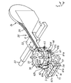
【図1】 本発明に係る電子部品実装装置の一実施の形態の全体構造を示す斜視図である。
【図2】 図1に示す電子部品実装装置の要部の側断面図である。
【図3】 図1に示す落下防止部材の配置を示す模式的平面図である。
【符号の説明】
10…機枠、15…基板支持装置、20…部品供給装置、30…装着機、40…装着ヘッド、41…吸着ノズル、61,62…第1および第2落下防止部材、63…検出センサ、P…部品(電子部品)、S…基板、Sa…装着面。[0001]
BACKGROUND OF THE INVENTION
The present invention relates to an electronic component mounting apparatus for manufacturing an electronic circuit board by mounting an electronic component on a printed board.
[0002]
[Prior art]
In order to mount an electronic component on a printed circuit board, cream solder is applied in advance to a predetermined position of the substrate by screen printing or the like, and the electronic component is mounted at that position and heated and soldered. A rotary type or gantry type electronic component mounting device is used for mounting each electronic component to a predetermined position on the printed circuit board. In either case, the printed circuit board is sucked and held by a mounting head that is a part of the mounting device. This is done by transferring the electronic components carried on to the printed circuit board surface.
[0003]
The mounting head is provided with a suction nozzle for mounting the component on the mounting surface of the substrate. The suction nozzle sucks the electronic component supplied at the suction station and moves to the mounting station through a predetermined first path. In this mounting station, circulation is repeatedly performed in which the electronic component is mounted at a predetermined position on the printed circuit board and moved again to the suction station through a predetermined second path.
[0004]
[Problems to be solved by the invention]
In the electronic component mounting apparatus described above, when the suction nozzle that sucks and holds the electronic component at the suction station transports the electronic component to the mounting station, the electronic component falls below the predetermined first path. There are no members to receive the dropped electronic components, so electronic components that have fallen to a place other than the specified location on the board (or a place other than the board) are erroneously mounted on the board, or there are insufficient parts. There was a problem of producing defective products. Further, when the electronic component is mounted at a predetermined position on the substrate at the mounting station and moved to the disposal station on the way to the suction station through the predetermined second path, the electronic component does not leave the suction nozzle as it is. Even when the parts are carried away and fall off the suction nozzle, there is no member for receiving the electronic parts dropped below the predetermined second path. There has been a problem in that electronic components that have fallen on the board are erroneously mounted on the board to produce defective products.
[0005]
Therefore, the present invention has been made to solve the above-described problems, and by placing a fall prevention member below the path through which the electronic component is conveyed, the dropped component is erroneously mounted on the board. The purpose is to prevent the production of defective products.
[0006]
[Means for Solving the Problems]
In order to solve the above-described problem, the constitutional feature of the invention according to
[0007]
The structural feature of the invention according to
[0008]
Further, the structural feature of the invention according to
[0009]
According to a fourth aspect of the present invention, there is provided a detection sensor for detecting the presence or absence of a part that has fallen on the fall prevention member.
[0010]
Further, the structural feature of the invention according to claim 5 is that when the detection sensor detects the presence of a component, the mounting of the component on the board is stopped according to the setting selected in advance, or the component on the board is It is to control to continue the mounting.
[0011]
[Operation and effect of the invention]
In the invention according to
[0012]
In the invention which concerns on
[0013]
In the invention according to
[0014]
In the invention according to claim 4 configured as described above, since the detection sensor for detecting the presence or absence of the part dropped on the fall prevention member is provided, the presence or absence of the part dropping is automatically and reliably detected by this detection sensor. can do.
[0015]
In the invention according to claim 5 configured as described above, the detection sensor detects the presence of a component when the detection sensor is set to continue mounting the component on the board when the presence of the component is detected. Then, the mounting of the component on the board is stopped, so that when the component falls from the suction nozzle, the mounting of the component on the board can be surely stopped. Therefore, it is possible to check the parts that have been dropped during the stop and set up a program to install the parts, and to install the parts that should be installed in the subsequent process based on this program. Can be prevented. In addition, when the detection sensor detects the presence of a component, the setting of the component to the board is stopped when the detection sensor detects the presence of the component. When a component falls from the suction nozzle, the mounting of the component on the substrate can be reliably stopped.
[0016]
DETAILED DESCRIPTION OF THE INVENTION
An embodiment of an electronic component mounting apparatus according to the present invention will be described below with reference to FIGS. FIG. 1 shows the overall structure of the electronic component mounting apparatus, and FIG. 2 shows a side cross section of the main part of the electronic component mounting apparatus. The electronic component mounting apparatus includes a rotary
[0017]
The
[0018]
The
[0019]
Next, the rotary
[0020]
In each of the eight pairs of
[0021]
A mounting
[0022]
As shown in FIG. 3, between the component suction station and the component mounting station, which are 180 degrees out of phase with each other, three stations of a flux application station, an image recognition station, and a θ correction station are provided at 45 ° intervals. And a component suction station are provided with a θ return station, a component disposal station, and a nozzle switching station at intervals of 45 degrees.
[0023]
A tip portion (component supply portion B) of the
[0024]
Below the flux application station, a
[0025]
In the θ return station, the rotation angle of the
[0026]
Further, as mainly shown in FIG. 3, the path below the path from the image recognition station to the component mounting station in the movement path (first path) of the
[0027]
The first and second
[0028]
A detection sensor 63 that detects the presence or absence of the electronic component P that has fallen on the first
[0029]
Similarly to the first
[0030]
In addition, the first and second
[0031]
In addition, although each
[0032]
Next, the operation of the above-described embodiment will be described. In order to simplify the description, a procedure for attaching one electronic component P to the substrate S will be described first. The control device of the electronic component mounting apparatus first positions the component extraction position at the tip of the
[0033]
In the image recognition station, image recognition of the electronic component P sucked and held by the
[0034]
In addition, after the electronic component P attracted and held by the
[0035]
When it is determined that the electronic component P is mounted, the control device continues production by the electronic component mounting device, and when it is determined that the electronic component P is not mounted, the control device uses the electronic component mounting device. Automatic recovery mounting is performed or the operation of the electronic component mounting apparatus is stopped. In addition, when it is determined that the electronic component P is sucked at the image recognition station but the electronic component P is determined not to be mounted at the component mounting station, the electronic component P is picked up by the suction nozzle. Since it is determined that it remains without being separated from 41, the control device takes the electronic component P away from the tip of the
[0036]
The above description has been given for one electronic component P. Actually, when this electronic component P is sucked by the
[0037]
During the operation of the above-described embodiment, the
[0038]
Further, when the electronic component P falls on the
[0039]
In addition, when the electronic component P falls on the
[0040]
The control device for the electronic component mounting apparatus described above stops mounting the electronic component P on the substrate S when the detection sensor 63 detects the presence of the electronic component P on the
[0041]
In the above-described embodiment, the shape of the
[0042]
In the embodiment described above, the total length of the
[0043]
In the embodiment described above, the first fall prevention member 61 (or the second fall prevention member 62) may be provided only in either the first path or the second path.
[0044]
In the above-described embodiment, the first and second
[0045]
Further, the detection sensor 63 is provided at each lower end portion of the
[0046]
Further, the present invention is not only applied to an electronic component mounting apparatus having a rotary type mounting machine, but also applied to an electronic component mounting apparatus having another type of mounting machine (for example, a gantry type mounting machine). Is possible.
[Brief description of the drawings]
FIG. 1 is a perspective view showing the overall structure of an embodiment of an electronic component mounting apparatus according to the present invention.
FIG. 2 is a side sectional view of a main part of the electronic component mounting apparatus shown in FIG.
FIG. 3 is a schematic plan view showing the arrangement of the fall prevention member shown in FIG. 1;
[Explanation of symbols]
DESCRIPTION OF
Claims (5)
前記第1経路のうち該経路と前記基板との間に前記部品装着ステーションから前記画像認識ステーションまでの経路に渡って少なくとも配設され、前記吸着ノズルの移動の際に前記吸着ノズルから落下する前記部品を受け止める第1落下防止部材と、前記第2経路のうち該経路と前記基板との間に前記部品装着ステーションから前記部品廃棄ステーションまでの経路に渡って少なくとも配設され、前記吸着ノズルの移動の際に前記吸着ノズルから落下する前記部品を受け止める第2落下防止部材と、のうち少なくとも何れか一方の落下防止部材を設けたことを特徴とする電子部品実装装置。 A plurality of suction nozzles is movably supported and arranged mounting machine on the circumference of the rotating body, the substrate in the horizontal direction is provided below the said mounting machine for mounting the components on instrumentation Chakumen substrate A substrate support device, and the mounting machine passes through an image recognition station that sequentially recognizes the components sucked by the suction nozzles from a component suction station where the suction nozzles sequentially suck the components. A first path to a component mounting station that sequentially mounts the component sucked by the suction nozzle on a predetermined position of the substrate, and a component remaining from the suction nozzle at the component mounting station from the component mounting station. Circulating and moving each of the suction nozzles through the second path to the parts suction station via the parts disposal station to be discarded, In the electronic component mounting device for moving the substrate so that a predetermined portion of the substrate is right below the component mounting station,
The first path is disposed at least over the path from the component mounting station to the image recognition station between the path and the substrate, and falls from the suction nozzle when the suction nozzle moves. A first fall-preventing member that receives a component; and at least a path from the component mounting station to the component disposal station between the path and the substrate of the second path, and the movement of the suction nozzle An electronic component mounting apparatus comprising: a second fall prevention member that receives the component falling from the suction nozzle at the time of at least one fall prevention member.
Priority Applications (1)
| Application Number | Priority Date | Filing Date | Title |
|---|---|---|---|
| JP2002154775A JP4040366B2 (en) | 2002-05-28 | 2002-05-28 | Electronic component mounting equipment |
Applications Claiming Priority (1)
| Application Number | Priority Date | Filing Date | Title |
|---|---|---|---|
| JP2002154775A JP4040366B2 (en) | 2002-05-28 | 2002-05-28 | Electronic component mounting equipment |
Publications (2)
| Publication Number | Publication Date |
|---|---|
| JP2003347793A JP2003347793A (en) | 2003-12-05 |
| JP4040366B2 true JP4040366B2 (en) | 2008-01-30 |
Family
ID=29771444
Family Applications (1)
| Application Number | Title | Priority Date | Filing Date |
|---|---|---|---|
| JP2002154775A Expired - Lifetime JP4040366B2 (en) | 2002-05-28 | 2002-05-28 | Electronic component mounting equipment |
Country Status (1)
| Country | Link |
|---|---|
| JP (1) | JP4040366B2 (en) |
Families Citing this family (3)
| Publication number | Priority date | Publication date | Assignee | Title |
|---|---|---|---|---|
| JP4777151B2 (en) * | 2006-06-07 | 2011-09-21 | Juki株式会社 | Component disposal box in component mounting equipment |
| JP5912625B2 (en) * | 2012-02-10 | 2016-04-27 | 富士機械製造株式会社 | Electronic circuit component mounting machine |
| CN104663017B (en) * | 2012-09-20 | 2017-06-13 | 富士机械制造株式会社 | Electronic circuit component mounter |
Family Cites Families (9)
| Publication number | Priority date | Publication date | Assignee | Title |
|---|---|---|---|---|
| JPH0899630A (en) * | 1994-09-30 | 1996-04-16 | Toyota Autom Loom Works Ltd | Load fall preventing fence for conveyor device |
| JP3537510B2 (en) * | 1994-10-31 | 2004-06-14 | 株式会社日立ハイテクインスツルメンツ | Electronic component automatic mounting device and electronic component mounting method |
| JP3235459B2 (en) * | 1996-04-25 | 2001-12-04 | 松下電器産業株式会社 | Conductive ball mounting device and conductive ball mounting method |
| JPH11150395A (en) * | 1997-11-17 | 1999-06-02 | Tdk Corp | Label with scale for electronic part feed case |
| JP2000102742A (en) * | 1998-09-29 | 2000-04-11 | Babcock Hitachi Kk | Coal pulverizer of coal-fired boiler |
| JP4224160B2 (en) * | 1999-03-18 | 2009-02-12 | パナソニック株式会社 | Electronic component mounting device |
| JP3821610B2 (en) * | 1999-06-18 | 2006-09-13 | 松下電器産業株式会社 | Tray feeder for supplying electronic components |
| JP2001077589A (en) * | 1999-09-09 | 2001-03-23 | Matsushita Electric Ind Co Ltd | Electronic component mounting equipment, electronic component feeding device used therein, electronic component housing case used therein, and electronic component mounting method using them |
| JP3719062B2 (en) * | 1999-09-20 | 2005-11-24 | 松下電器産業株式会社 | Electronic component mounting equipment |
-
2002
- 2002-05-28 JP JP2002154775A patent/JP4040366B2/en not_active Expired - Lifetime
Also Published As
| Publication number | Publication date |
|---|---|
| JP2003347793A (en) | 2003-12-05 |
Similar Documents
| Publication | Publication Date | Title |
|---|---|---|
| US4731923A (en) | Apparatus and method for mounting circuit element on printed circuit board | |
| JP6199798B2 (en) | Electronic component mounting device | |
| JP6309830B2 (en) | Component mounting device | |
| JP3398109B2 (en) | Electronic component mounting device | |
| JP4387745B2 (en) | Electronic component mounting device | |
| JP6293454B2 (en) | Electronic component mounting device | |
| JP6301635B2 (en) | Board inspection method | |
| JP6378053B2 (en) | Component mounting machine and component mounting head | |
| JP5253540B2 (en) | Electronic component mounting device | |
| CN111096097B (en) | Component mounting apparatus and component drop determination method | |
| JP3554615B2 (en) | Electronic component mounting device | |
| JP4040366B2 (en) | Electronic component mounting equipment | |
| CN111096104B (en) | Component mounting apparatus and retry method for component pickup | |
| JP3746127B2 (en) | Component mounting device | |
| JP7493059B2 (en) | Component placement machine | |
| JP2008159623A (en) | Part pick-up device in part feeding apparatus | |
| JP2003298291A (en) | Method and system for mounting electronic component | |
| JP7235525B2 (en) | Parts mounting machine | |
| JP3737922B2 (en) | Electronic component mounting device | |
| JP2003258500A (en) | Method and apparatus of confirming part installation | |
| JP4681173B2 (en) | Taping device | |
| KR101632264B1 (en) | Apparatus for mounting component | |
| JPH09326591A (en) | Electronic part mounting device and method | |
| JP3623982B2 (en) | Electronic component automatic placement equipment | |
| JP4757906B2 (en) | Electronic component mounting device |
Legal Events
| Date | Code | Title | Description |
|---|---|---|---|
| A621 | Written request for application examination |
Free format text: JAPANESE INTERMEDIATE CODE: A621 Effective date: 20050523 |
|
| A977 | Report on retrieval |
Free format text: JAPANESE INTERMEDIATE CODE: A971007 Effective date: 20070719 |
|
| A131 | Notification of reasons for refusal |
Free format text: JAPANESE INTERMEDIATE CODE: A131 Effective date: 20070724 |
|
| A521 | Request for written amendment filed |
Free format text: JAPANESE INTERMEDIATE CODE: A523 Effective date: 20070919 |
|
| TRDD | Decision of grant or rejection written | ||
| A01 | Written decision to grant a patent or to grant a registration (utility model) |
Free format text: JAPANESE INTERMEDIATE CODE: A01 Effective date: 20071023 |
|
| A61 | First payment of annual fees (during grant procedure) |
Free format text: JAPANESE INTERMEDIATE CODE: A61 Effective date: 20071107 |
|
| FPAY | Renewal fee payment (event date is renewal date of database) |
Free format text: PAYMENT UNTIL: 20101116 Year of fee payment: 3 |
|
| R150 | Certificate of patent or registration of utility model |
Ref document number: 4040366 Country of ref document: JP Free format text: JAPANESE INTERMEDIATE CODE: R150 Free format text: JAPANESE INTERMEDIATE CODE: R150 |
|
| FPAY | Renewal fee payment (event date is renewal date of database) |
Free format text: PAYMENT UNTIL: 20101116 Year of fee payment: 3 |
|
| FPAY | Renewal fee payment (event date is renewal date of database) |
Free format text: PAYMENT UNTIL: 20111116 Year of fee payment: 4 |
|
| R250 | Receipt of annual fees |
Free format text: JAPANESE INTERMEDIATE CODE: R250 |
|
| FPAY | Renewal fee payment (event date is renewal date of database) |
Free format text: PAYMENT UNTIL: 20121116 Year of fee payment: 5 |
|
| R250 | Receipt of annual fees |
Free format text: JAPANESE INTERMEDIATE CODE: R250 |
|
| FPAY | Renewal fee payment (event date is renewal date of database) |
Free format text: PAYMENT UNTIL: 20121116 Year of fee payment: 5 |
|
| FPAY | Renewal fee payment (event date is renewal date of database) |
Free format text: PAYMENT UNTIL: 20131116 Year of fee payment: 6 |
|
| R250 | Receipt of annual fees |
Free format text: JAPANESE INTERMEDIATE CODE: R250 |
|
| R250 | Receipt of annual fees |
Free format text: JAPANESE INTERMEDIATE CODE: R250 |
|
| R250 | Receipt of annual fees |
Free format text: JAPANESE INTERMEDIATE CODE: R250 |
|
| R250 | Receipt of annual fees |
Free format text: JAPANESE INTERMEDIATE CODE: R250 |
|
| R250 | Receipt of annual fees |
Free format text: JAPANESE INTERMEDIATE CODE: R250 |
|
| R250 | Receipt of annual fees |
Free format text: JAPANESE INTERMEDIATE CODE: R250 |
|
| S533 | Written request for registration of change of name |
Free format text: JAPANESE INTERMEDIATE CODE: R313533 |
|
| R350 | Written notification of registration of transfer |
Free format text: JAPANESE INTERMEDIATE CODE: R350 |
|
| R250 | Receipt of annual fees |
Free format text: JAPANESE INTERMEDIATE CODE: R250 |
|
| R250 | Receipt of annual fees |
Free format text: JAPANESE INTERMEDIATE CODE: R250 |
|
| R250 | Receipt of annual fees |
Free format text: JAPANESE INTERMEDIATE CODE: R250 |
|
| R250 | Receipt of annual fees |
Free format text: JAPANESE INTERMEDIATE CODE: R250 |
|
| EXPY | Cancellation because of completion of term |