JP3554615B2 - Electronic component mounting device - Google Patents
Electronic component mounting device Download PDFInfo
- Publication number
- JP3554615B2 JP3554615B2 JP20515295A JP20515295A JP3554615B2 JP 3554615 B2 JP3554615 B2 JP 3554615B2 JP 20515295 A JP20515295 A JP 20515295A JP 20515295 A JP20515295 A JP 20515295A JP 3554615 B2 JP3554615 B2 JP 3554615B2
- Authority
- JP
- Japan
- Prior art keywords
- mounting
- electronic component
- suction nozzle
- suction
- nozzle
- Prior art date
- Legal status (The legal status is an assumption and is not a legal conclusion. Google has not performed a legal analysis and makes no representation as to the accuracy of the status listed.)
- Expired - Fee Related
Links
Images


Classifications
-
- H—ELECTRICITY
- H05—ELECTRIC TECHNIQUES NOT OTHERWISE PROVIDED FOR
- H05K—PRINTED CIRCUITS; CASINGS OR CONSTRUCTIONAL DETAILS OF ELECTRIC APPARATUS; MANUFACTURE OF ASSEMBLAGES OF ELECTRICAL COMPONENTS
- H05K13/00—Apparatus or processes specially adapted for manufacturing or adjusting assemblages of electric components
- H05K13/04—Mounting of components, e.g. of leadless components
- H05K13/0404—Pick-and-place heads or apparatus, e.g. with jaws
- H05K13/0408—Incorporating a pick-up tool
- H05K13/041—Incorporating a pick-up tool having multiple pick-up tools
-
- H—ELECTRICITY
- H05—ELECTRIC TECHNIQUES NOT OTHERWISE PROVIDED FOR
- H05K—PRINTED CIRCUITS; CASINGS OR CONSTRUCTIONAL DETAILS OF ELECTRIC APPARATUS; MANUFACTURE OF ASSEMBLAGES OF ELECTRICAL COMPONENTS
- H05K13/00—Apparatus or processes specially adapted for manufacturing or adjusting assemblages of electric components
- H05K13/04—Mounting of components, e.g. of leadless components
- H05K13/0404—Pick-and-place heads or apparatus, e.g. with jaws
- H05K13/0408—Incorporating a pick-up tool
- H05K13/0409—Sucking devices
-
- H—ELECTRICITY
- H05—ELECTRIC TECHNIQUES NOT OTHERWISE PROVIDED FOR
- H05K—PRINTED CIRCUITS; CASINGS OR CONSTRUCTIONAL DETAILS OF ELECTRIC APPARATUS; MANUFACTURE OF ASSEMBLAGES OF ELECTRICAL COMPONENTS
- H05K13/00—Apparatus or processes specially adapted for manufacturing or adjusting assemblages of electric components
- H05K13/08—Monitoring manufacture of assemblages
- H05K13/082—Integration of non-optical monitoring devices, i.e. using non-optical inspection means, e.g. electrical means, mechanical means or X-rays
-
- Y—GENERAL TAGGING OF NEW TECHNOLOGICAL DEVELOPMENTS; GENERAL TAGGING OF CROSS-SECTIONAL TECHNOLOGIES SPANNING OVER SEVERAL SECTIONS OF THE IPC; TECHNICAL SUBJECTS COVERED BY FORMER USPC CROSS-REFERENCE ART COLLECTIONS [XRACs] AND DIGESTS
- Y10—TECHNICAL SUBJECTS COVERED BY FORMER USPC
- Y10T—TECHNICAL SUBJECTS COVERED BY FORMER US CLASSIFICATION
- Y10T29/00—Metal working
- Y10T29/53—Means to assemble or disassemble
- Y10T29/5313—Means to assemble electrical device
- Y10T29/53191—Means to apply vacuum directly to position or hold work part
Landscapes
- Engineering & Computer Science (AREA)
- Manufacturing & Machinery (AREA)
- Microelectronics & Electronic Packaging (AREA)
- Operations Research (AREA)
- Supply And Installment Of Electrical Components (AREA)
- Manipulator (AREA)
Description
【0001】
【発明の属する技術分野】
本発明は、装着ヘッドに垂下した吸着ノズルを、当該装着ヘッドと共に間欠送りし、吸着した電子部品を基板などに装着する電子部品装着装置に関するものである。
【0002】
【従来の技術】
従来、この種の電子部品装着装置として、特開平5−226884号公報に記載のものが知られている。この電子部品装着装置では、装置本体を挟んで、装置本体に電子部品を供給する供給系と、装置本体から電子部品の装着を受ける装着系とが、相互に平行に配設されている。装置本体には、回転テーブルが設けられており、回転テーブルの外周部には、各6本の吸着ノズルを保持した装着ヘッドが、等間隔に12個、配設されている。回転テーブルは間欠回転しながら、装着ヘッドを供給系と装着系との間で回転送りし、その際、吸着ノズルは、供給系から電子部品を吸着し、これを装着系の基板に装着する。
【0003】
この場合、各吸着ノズルが臨む供給系の吸着ステーションから装着系の装着ステーションに至る搬送経路には、電子部品の吸着姿勢を画像認識すると共にその姿勢を補正するなどのアクセスを行う各種のステーションが設けられ、また装着ステーションから吸着ステーションに至る搬送経路には、吸着ノズルの選択や吸着ノズルのレベル調整などのアクセスを行う各種のステーションが設けられている。また、吸着ステーションの一つ手前のステーションでは、電子部品の吸着を確実なものとするため、吸着ノズルの前後方向の位置補正が行われると共に、使用するノズルの突出の程度および使用しないノズルの突出の程度を検出する検出装置が設けられている。
【0004】
一方、各装着ヘッドには、6本の吸着ノズルが出没自在に垂下されており、またこの6本の吸着ノズルは、装着する電子部品に合わせて適宜交換できるように、装着ヘッドに対し着脱自在に構成されている。そして、この交換作業は、一般的に装着ステーションで行われる。
【0005】
【発明が解決しようとする課題】
このような従来の電子部品装着装置では、吸着ノズルの交換(着脱)が装着ステーションで行われる一方、吸着ノズルの突出レベルの検出が吸着ステーションの一つ手前のステーションで行われる。このため、吸着ノズルが装着不良により過度に垂れ下がっていると、この過度の垂下状態が検出されるまでの間、すなわち、吸着ノズルの選択や吸着ノズルのレベルを調整する各種のステーションを通過する間に、この垂れ下がった吸着ノズルが、装置本体の構成部品に衝突して、吸着ノズル或いは構成部品を破損するおそれがあった。また、ねじの緩みなどにより、吸着ノズルが徐々に垂れ下がってくる場合にあっても、周方向の一箇所の検出では、発見(検出)が遅れるおそれがあった。
【0006】
本発明は、吸着ノズルの過度の垂下状態を迅速に検出することができる電子部品装着装置を提供することをその目的としている。
【0007】
【課題を解決するための手段】
請求項1の電子部品装着装置は、装着ヘッドに垂下した複数本の吸着ノズルを、装着ヘッドと共に間欠送りし、電子部品の装着位置および吸着ノズルの装着位置を兼ねる装着ステーション、電子部品の吸着に先立ち該当する吸着ノズルを準備するノズル調整ステーションおよび電子部品を吸着ノズルに吸着する吸着ステーションの順でこれらに臨ませる電子部品装着装置において、装着ステーションとノズル調整ステーションとの間に、吸着ノズルの過度な垂下状態を検出するノズルレベル検出手段を配設したことを特徴とする。
【0008】
この構成によれば、ノズルレベル検出手段により、吸着ノズルの過度な垂下状態が、装着ステーションとノズル調整ステーションとの間で検出されるため、装着ミスやねじの緩みなどにより過度に垂れ下がった吸着ノズルを、ノズル調整ステーションの手前で検出することができる。このため、吸着ノズルにアクセスする部品が配設されているノズル調整ステーションを、過度に垂れ下がった吸着ノズルが通過するのを回避することができる。
【0009】
また、請求項2の電子部品装着装置は、間欠送りされてくる吸着ノズルの直下近傍に臨んで、装着がキャンセルされた電子部品を吸着ノズルから相対的に掻き落とすチップ排出板を備えた電子部品装着装置において、チップ排出板の変位を検出する検出器を備えたことを特徴とする。
【0010】
この構成によれば、吸着ノズルが適切に装着されている場合には、吸着ノズルの先端がチップ排出板の上側近傍を通過し、吸着ノズルが垂れ下がって不適切に装着されている場合には、吸着ノズルの先端がチップ排出板の干渉してこれを先方を変位させる。すなわち、電子部品を掻き落とすチップ排出板を利用して、吸着ノズルの装着不備を検出することができると共に、複数本の吸着ノズルに対応して設けたチップ排出板により、複数本の吸着ノズルの装着不備を同時に検出することができる。また、このチップ排出板は、吸着ノズルの調整に支障を生じないように、装着ステーションとノズル調整ステーションとの間のステーションに設けられている。このため、過度に垂れ下がった吸着ノズルがノズル調整ステーションを通過するのを回避することができる。
【0011】
【発明の実施の形態】
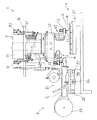
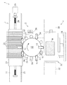
以下、添付図面を参照して、本発明の一実施形態に係る電子部品装着装置について説明する。図1は電子部品装着装置の側面図であり、図2はその平面図である。両図に示すように、この電子部品装着装置1は、装着装置本体2を挟んで相互に平行に、電子部品Aを供給する供給系3と、電子部品Aを基板Bに装着する装着系4とを配して構成されている。装着装置本体2には、駆動系の主体を為すインデックスユニット11と、これに連結された回転テーブル12と、回転テーブル12の外周部に搭載した複数個(12個)の装着ヘッド13とが設けられており、回転テーブル12は、インデックスユニット11により、装着ヘッド13の個数に対応する間欠ピッチで間欠回転される。回転テーブル12が間欠回転すると、各装着ヘッド13に搭載した吸着ノズル14が供給系3および装着系4に適宜臨み、供給系3から供給された電子部品Aを吸着した後、装着系4に回転搬送し、装着系4に導入した基板Bにこれを装着する。
【0012】
供給系3は、基板Bに装着する電子部品Aの種類に応じた数のテープカセット21を有し、テープカセット21は、一対のガイドレール22,22にスライド自在に案内された供給台23に、横並びに着脱自在に設けられている。供給台23には、そのスライド方向にボールねじ24が螺合しており、供給台23は、ボールねじ24の一方の端に連結した送りモータ25の正逆回転により進退され、装着ヘッド13の吸着位置にテープカセット21を選択的に臨ませる。各テープカセット21には、所定のピッチで電子部品Aが装填されたキャリアテープCが、テープリール26に巻き出された状態で搭載されており、電子部品Aは、テープリール26から巻き出されたキャリアテープCから随時、吸着ノズル14により吸着されてゆく。
【0013】
装着系4は、載置した基板BをX軸方向およびY軸方向に移動させるXYテーブル31と、XYテーブル31の前後に配設した搬入搬送路32および搬出搬送路33と、搬入搬送路32上の基板BをXYテーブル31に、同時にXYテーブル31上の基板Bを搬出搬送路33に移送する基板移送装置34とで、構成されている。搬入搬送路32の下流端まで送られてきた基板Bは、基板移送装置34により、XYテーブル31上に移送され、同時に電子部品Aの装着が完了したXYテーブル31上の基板Bは、この基板移送装置34により、搬出搬送路33に移送される。XYテーブル31上に導入された基板Bは、XYテーブル31により適宜移動され、各装着ヘッド13により次々と送られてくる電子部品Aに対応して、その部品装着部位を装着位置に臨ませ、各吸着ノズル14から電子部品Aの装着を受ける。
【0014】
装着装置本体2は、支持台15上に駆動系の主体を為すインデックスユニット11を有しており、インデックスユニット11は、回転テーブル12を間欠回転させると共に、回転テーブル12の間欠周期に同期(連動)させ、装着装置本体2の各種の装置を作動させる。
【0015】
回転テーブル12は、インデックスユニット11から垂下した鉛直軸41に固定され、平面視時計廻りに間欠回転する。回転テーブル12の外周部には、各2本のロッド42,42を介して、周方向に等間隔に12個の装着ヘッド13が、上下動自在に取り付けられている。この場合、回転テーブル12の間欠回転は、装着ヘッド13の数に合わせて一回転に対して12間欠周期となっており、この間欠回転により公転する各装着ヘッド13は、吸着位置および装着位置を含む12箇所の停止位置(ステーション)にそれぞれ停止する。
【0016】
各装着ヘッド13には、周方向に等間隔に配設した複数本(実施例では5本)の吸着ノズル14が、それぞれ出没自在に、かつ全体として鉛直軸廻りに公転可能に取り付けられている。吸着ノズル14は、5本のうちから電子部品Aの大きさなどに対応して、適切な一の吸着ノズル14を選択できるようになっている。そして、この選択は、選択した一の吸着ノズル14を、装着ヘッド13のノズルセット位置に公転移動させかつ突出させることにより、行われる。また、この5本の吸着ノズル14は、装着ヘッド13に対し着脱自在に構成されており、適宜交換できるようになっている。
【0017】
一方、回転テーブル12の間欠回転に伴う吸着位置および装着位置を含む12箇所の停止位置には、吸着ノズル14にアクセスする各種の装置が、支持台15に取り付けられるようにして、組み込まれている。
【0018】
吸着位置(吸着ステーション)には、装着ヘッド13を電子部品Aの吸着のために下降させる装着ヘッド昇降装置51が、上記のロッド42に連結されるようにして設けられている。同様に装着位置(装着ステーション)にも、装着ヘッド13を電子部品Aの装着のために下降させる装着ヘッド昇降装置52が、設けられている。なお、両装着ヘッド昇降装置51,52は、アーム長が異なるだけで、基本構造は同一である。
【0019】
また、図2に示すように、時計廻りに装着位置の次の次の停止位置(ノズル調整ステーション)には、吸着ノズル14を公転させ、選択した一の吸着ノズル14を外側に位置するノズルセット位置に移動させるノズル選択装置53が、その次の停止位置(ノズル調整ステーション)には、装着ヘッド13を下降させ突当て台に突き当てて不要な吸着ノズル14を没入させると共に、装着ヘッド13を上昇させながら選択した吸着ノズル14を突出させるノズル出没装置54が、更にその次の停止位置(ノズル調整ステーション)には、突出した吸着ノズル14の突出長を調整するノズル長さ調整装置55が、それぞれ組み込まれている。
【0020】
同様に、続く吸着位置の一つ手前の停止位置には、吸着ノズル14を公転させ、吸着位置に臨む吸着ノズル14の左右方向(供給台の進退方向に直交する方向)の位置を補正するノズル位置補正装置56が設けられている。なお、図示しないが、この停止位置には、使用するために突出している吸着ノズル14と、使用しない他の吸着ノズル14のそれぞれのレベルを検出する検出装置も設けられている。
【0021】
また、吸着位置の次の停止位置には、吸着ノズル14を公転させ、吸着ノズル14を元のノズルセット位置に復帰させるノズル復帰装置57が、その次の次の停止位置には、吸着した電子部品Aの姿勢(水平面内における姿勢)を画像認識する部品認識装置58が、その次の停止位置には、部品認識装置58の認識結果に基づいて、吸着ノズル14を公転させ、吸着した電子部品Aを装着時の姿勢になるように補正する部品角度補正装置59が、それぞれ組み込まれている。
【0022】
さらに、装着位置の次の停止位置(部品排出ステーション)には、上記の部品認識装置58により、補正不能と認識され装着をキャンセルした電子部品Aを、吸着ノズル14から取り去る部品排出装置60が設けられている。そして、詳細は後述するが、この部品排出装置60は、吸着ノズル14の装着ヘッド13への装着不備を検出するノズルレベル検出手段を兼ねている。
【0023】
ここで、任意の一の装着ヘッド13の動作を例に、装着装置本体2の一連の動作を簡単に説明する。装着位置において基板Bに電子部品Aを装着した装着ヘッド13は、間欠回転する回転テーブル12により吸着位置に向かって公転送りされてゆき、制御指令に基づく、吸着ノズル14の選択、吸着ノズル14の突出・没入、突出長さ調整、および位置補正が順次行われながら、吸着位置に達する。一方、吸着系3では、装着ヘッド13が吸着位置の一つ手前の停止位置から吸着位置に移動してくる間に、制御指令に基づき、供給台23を進退させ、該当する電子部品用のテープカセット21を吸着位置に臨ませる。
【0024】
ここで電子部品Aを吸着した装着ヘッド13は、今度は装着位置に向かって公転送りされてゆき、制御指令に基づく、吸着ノズル14のノズルセット位置への復帰、吸着した電子部品Aの認識、およびこれに基ずく電子部品Aの角度補正が順次行われながら、装着位置に達する。一方、装着系4では、装着ヘッド13が装着位置の一つ手前の停止位置から装着位置に移動してくる間に、制御指令に基づき、XYテーブル31を作動させて、基板Bの部品装着部位を装着位置に臨ませる。そして、装着ヘッド昇降装置52により装着ヘッド13が下降され、基板Bに電子部品Aが装着される。
【0025】
次に、図3を参照して、部品排出装置60について詳細に説明する。同図に示すように、部品排出装置60は、電子部品Aを吸着ノズル14からを掻き落とすチップ排出板71と、チップ排出板71の変位を検出する検出器72と、掻き落とされた電子部品Aを受けるボックス73とで構成されている。チップ排出板71は、一端をシャーシ61に固定され、水平に延びて吸着ノズル14の搬送経路の下側近傍に臨んでいる。間欠送りされてくる吸着ノズル14の先端は、チップ排出板71の上端すれすれに通過し、装着をキャンセルされた電子部品Aは、チップ排出板71に突き当たって下方のボックス73に落とし込まれる。なお、チップ排出板71の手前で吸着ノズル14のエアー吸着は解除される。
【0026】
チップ排出板71の先端下部は、水平に折曲げられており、この折曲部74が検出器72の近接センサ75に対峙している。検出器72は、この近接センサ75と近接センサ75を保持するホルダ76とで構成され、ホルダ76により、図外のシャーシに取り付けられている。この場合、チップ排出板71が変位してその折曲部74が近接センサ75からずれることにより、チップ排出板71を介して吸着ノズル14の装着不備が検出される。
【0027】
図4に示すように、装着位置(装着ステーション)において装着ヘッド13にセットした吸着ノズル14が、装着ミスにより垂れ下がった状態で装着されると、間欠送りされてきた吸着ノズル14がチップ排出板71に干渉する。この干渉により、チップ排出板71は先方に押され湾曲し、更に上向きに捻られ、吸着ノズル14が乗り越えたところで元に戻る。このチップ排出板71の湾曲に伴って、チップ排出板71の折曲部74が近接センサ75から位置ずれしてゆき、チップ排出板71の変位、すなわち吸着ノズル14が過度に垂れ下がって装着されている状態が検出される。そして、この検出結果により装置の運転が停止する。
【0028】
以上のように本実施形態によれば、吸着ノズル14がこれにアクセスするノズル選択装置53、ノズル出没装置54、ノズル長さ調整装置55などの位置(ステーション)に達する前に、その装着不備が検出されるので、吸着ノズル14の間欠送りが続行されることがなく、垂れ下がった吸着ノズル14が、ノズル出没装置54の突当て台などの構成部品に干渉するなどの事態を回避することができる。これにより、吸着ノズル14の装着ミスやねじの緩みなどによる吸着ノズル14の破損および構成部品の破損などを未然に防止することができる。また、この検出をチップ排出板71を利用して行っているので、検出装置を簡単かつ低コストで構成することができる。
【0029】
なお、本実施形態では、吸着ノズルの過度な垂下状態を検出する検出手段を、チップ排出板を利用して構成したが、光センサなどを用い、チップ排出板とは別に構成するようにしてもよい。また、近接センサに代えてフォトインタラプタやマイクロスイッチなどで検出器を構成してもよい。
【0030】
【発明の効果】
以上のように本発明の電子部品装着装置によれば、装着ステーションとノズル調整ステーションとの間で、吸着ノズルの過度な垂下状態を検出することができるので、吸着ノズルが他の構成部品と干渉し易い位置に達する前に、装置の運転を停止させることができ、装着不備に基づく吸着ノズルや構成部品の破損を有効に防止することができる。また請求項2の発明によれば、既存のチップ排出板を利用して、検出装置を簡単に構成することができる。
【図面の簡単な説明】
【図1】本発明の一実施形態に係る電子部品装着装置の側面図である。
【図2】実施形態に係る電子部品装着装置の平面図である。
【図3】装着装置本体の部品排出装置の構造図である。
【図4】装着装置本体の部品排出装置のノズルレベルを検出している状態を表した構造図である。
【符号の説明】
1 電子部品装着装置
2 装着本体
13 装着ヘッド
14 吸着ノズル
60 部品排出装置
71 チップ排出板
72 検出器
75 近接センサ
A 電子部品[0001]
TECHNICAL FIELD OF THE INVENTION
BACKGROUND OF THE INVENTION 1. Field of the Invention The present invention relates to an electronic component mounting apparatus that intermittently sends a suction nozzle hanging down to a mounting head together with the mounting head and mounts the sucked electronic component on a substrate or the like.
[0002]
[Prior art]
2. Description of the Related Art Conventionally, as an electronic component mounting apparatus of this type, an apparatus described in Japanese Patent Application Laid-Open No. 5-226888 is known. In this electronic component mounting apparatus, a supply system for supplying an electronic component to the device main body and a mounting system for receiving the mounting of the electronic component from the device main body are arranged in parallel with each other with the device main body interposed therebetween. A rotary table is provided in the apparatus main body, and twelve mounting heads each holding six suction nozzles are arranged at equal intervals on an outer peripheral portion of the rotary table. While the rotary table is intermittently rotating, the mounting head is rotationally fed between the supply system and the mounting system, and at this time, the suction nozzle sucks the electronic component from the supply system and mounts the electronic component on the substrate of the mounting system.
[0003]
In this case, on the transport path from the supply suction station facing each suction nozzle to the mounting mounting station, various stations for performing image recognition of the suction posture of the electronic component and performing access such as correcting the posture are provided. A variety of stations are provided on the transport path from the mounting station to the suction station for selecting suction nozzles and adjusting suction nozzle levels. In addition, at a station just before the suction station, the position of the suction nozzle is corrected in the front-rear direction in order to ensure the suction of the electronic component, and the degree of protrusion of the used nozzles and the protrusion of the unused nozzles are corrected. And a detection device for detecting the degree of
[0004]
On the other hand, six suction nozzles are suspended from each mounting head so that they can come and go, and these six suction nozzles are detachable from the mounting head so that they can be replaced as appropriate according to the electronic components to be mounted. Is configured. This replacement work is generally performed at the mounting station.
[0005]
[Problems to be solved by the invention]
In such a conventional electronic component mounting apparatus, replacement (detachment) of the suction nozzle is performed at the mounting station, while detection of the protrusion level of the suction nozzle is performed at a station immediately before the suction station. Therefore, if the suction nozzle is excessively sagged due to improper mounting, the excessive drooping state is detected until the excessively sagging state is detected, that is, while passing through various stations for selecting the suction nozzle and adjusting the level of the suction nozzle. In addition, there is a risk that the hanging suction nozzle collides with a component of the apparatus main body and damages the suction nozzle or the component. Further, even when the suction nozzle is gradually drooping due to loosening of the screw or the like, detection (detection) may be delayed in detecting one location in the circumferential direction.
[0006]
SUMMARY OF THE INVENTION It is an object of the present invention to provide an electronic component mounting device capable of quickly detecting an excessive drooping state of a suction nozzle.
[0007]
[Means for Solving the Problems]
According to the electronic component mounting apparatus of the first aspect, a plurality of suction nozzles hanging down from a mounting head are intermittently fed together with the mounting head, and a mounting station serving as a mounting position of an electronic component and a mounting position of a suction nozzle is provided. In the electronic component mounting apparatus, which faces the nozzle adjustment station for preparing the corresponding suction nozzle and the suction station for sucking the electronic component to the suction nozzle in advance, the excess of the suction nozzle is set between the mounting station and the nozzle adjustment station. And a nozzle level detecting means for detecting a drooping state.
[0008]
According to this configuration, since the excessively drooping state of the suction nozzle is detected between the mounting station and the nozzle adjustment station by the nozzle level detecting means, the suction nozzle that has drooped excessively due to a mounting error, a loose screw, or the like. Can be detected before the nozzle adjustment station. For this reason, it is possible to prevent an excessively drooping suction nozzle from passing through a nozzle adjustment station in which components for accessing the suction nozzle are provided.
[0009]
Further, the electronic component mounting apparatus according to
[0010]
According to this configuration, when the suction nozzle is properly mounted, the tip of the suction nozzle passes near the upper side of the chip discharge plate, and when the suction nozzle hangs down and is improperly mounted, The tip of the suction nozzle interferes with the chip discharge plate and displaces the tip. That is, it is possible to detect improper mounting of the suction nozzles by using the chip discharge plate that scrapes off the electronic components, and it is also possible to detect a plurality of suction nozzles by using the chip discharge plates provided corresponding to the plurality of suction nozzles. Improper mounting can be detected at the same time. The chip ejection plate is provided at a station between the mounting station and the nozzle adjustment station so as not to hinder the adjustment of the suction nozzle. For this reason, it is possible to prevent the suction nozzle that has drooped excessively from passing through the nozzle adjustment station.
[0011]
BEST MODE FOR CARRYING OUT THE INVENTION
Hereinafter, an electronic component mounting apparatus according to an embodiment of the present invention will be described with reference to the accompanying drawings. FIG. 1 is a side view of the electronic component mounting apparatus, and FIG. 2 is a plan view thereof. As shown in FIGS. 1 and 2, the electronic component mounting apparatus 1 includes a
[0012]
The
[0013]
The mounting system 4 includes an XY table 31 for moving the mounted substrate B in the X-axis direction and the Y-axis direction, a carry-in
[0014]
The mounting apparatus
[0015]
The
[0016]
A plurality (five in this embodiment) of
[0017]
On the other hand, various devices for accessing the
[0018]
At the suction position (suction station), a mounting
[0019]
Further, as shown in FIG. 2, at the next stop position (nozzle adjustment station) next to the mounting position in the clockwise direction, the
[0020]
Similarly, a nozzle that revolves the
[0021]
At the next stop position after the suction position, a
[0022]
Further, at the stop position (component discharge station) next to the mounting position, there is provided a
[0023]
Here, a series of operations of the mounting apparatus
[0024]
Here, the mounting
[0025]
Next, the
[0026]
The lower end of the
[0027]
As shown in FIG. 4, when the
[0028]
As described above, according to the present embodiment, before the
[0029]
In the present embodiment, the detection means for detecting the excessive drooping state of the suction nozzle is configured using the chip discharge plate, but may be configured separately from the chip discharge plate using an optical sensor or the like. Good. Further, the detector may be configured by a photo interrupter, a micro switch, or the like instead of the proximity sensor.
[0030]
【The invention's effect】
As described above, according to the electronic component mounting apparatus of the present invention, an excessive drooping state of the suction nozzle can be detected between the mounting station and the nozzle adjustment station. The operation of the apparatus can be stopped before reaching a position where it is easy to perform, and it is possible to effectively prevent damage to the suction nozzle and components due to improper mounting. According to the second aspect of the present invention, the detection device can be easily configured by using the existing chip ejection plate.
[Brief description of the drawings]
FIG. 1 is a side view of an electronic component mounting apparatus according to an embodiment of the present invention.
FIG. 2 is a plan view of the electronic component mounting apparatus according to the embodiment.
FIG. 3 is a structural view of a component discharging device of the mounting device main body.
FIG. 4 is a structural diagram showing a state in which a nozzle level of a component discharging device of the mounting device main body is detected.
[Explanation of symbols]
REFERENCE SIGNS LIST 1 electronic
Claims (2)
前記装着ステーションと前記ノズル調整ステーションとの間に、前記吸着ノズルの過度な垂下状態を検出するノズルレベル検出手段を配設したことを特徴とする電子部品装着装置。A plurality of suction nozzles hanging down from the mounting head are intermittently fed together with the mounting head, and a mounting station serving also as a mounting position of the electronic component and a mounting position of the suction nozzle, a nozzle for preparing a corresponding suction nozzle prior to the suction of the electronic component. In the electronic component mounting device, which faces the adjustment station and the suction station for sucking the electronic component to the suction nozzle in this order,
An electronic component mounting apparatus, comprising: a nozzle level detecting unit that detects an excessive drooping state of the suction nozzle between the mounting station and the nozzle adjustment station.
前記チップ排出板の変位を検出する検出器を備えたことを特徴とする電子部品装着装置。In an electronic component mounting apparatus including a chip discharge plate that relatively scrapes the mounted electronic component from the suction nozzle, facing the vicinity immediately below the suction nozzle that is intermittently fed,
An electronic component mounting device comprising a detector for detecting a displacement of the chip ejection plate.
Priority Applications (2)
| Application Number | Priority Date | Filing Date | Title |
|---|---|---|---|
| JP20515295A JP3554615B2 (en) | 1995-07-19 | 1995-07-19 | Electronic component mounting device |
| US08/684,951 US5661239A (en) | 1995-07-19 | 1996-07-19 | Electronic parts-mounting apparatus |
Applications Claiming Priority (1)
| Application Number | Priority Date | Filing Date | Title |
|---|---|---|---|
| JP20515295A JP3554615B2 (en) | 1995-07-19 | 1995-07-19 | Electronic component mounting device |
Publications (2)
| Publication Number | Publication Date |
|---|---|
| JPH0936593A JPH0936593A (en) | 1997-02-07 |
| JP3554615B2 true JP3554615B2 (en) | 2004-08-18 |
Family
ID=16502286
Family Applications (1)
| Application Number | Title | Priority Date | Filing Date |
|---|---|---|---|
| JP20515295A Expired - Fee Related JP3554615B2 (en) | 1995-07-19 | 1995-07-19 | Electronic component mounting device |
Country Status (2)
| Country | Link |
|---|---|
| US (1) | US5661239A (en) |
| JP (1) | JP3554615B2 (en) |
Cited By (1)
| Publication number | Priority date | Publication date | Assignee | Title |
|---|---|---|---|---|
| CN106112525A (en) * | 2016-08-25 | 2016-11-16 | 瀚德汽车产品(苏州)有限公司 | A kind of full automatic assembly machine for assembling automatic clearance adjuster governor motion |
Families Citing this family (13)
| Publication number | Priority date | Publication date | Assignee | Title |
|---|---|---|---|---|
| JP3549073B2 (en) * | 1995-09-11 | 2004-08-04 | 松下電器産業株式会社 | Electronic component mounting method and electronic component mounting device |
| JP3245081B2 (en) * | 1997-02-04 | 2002-01-07 | 松下電器産業株式会社 | Electronic component mounting machine |
| US5953812A (en) * | 1997-07-03 | 1999-09-21 | Schlumberger Technologies, Inc. | Misinsert sensing in pick and place tooling |
| DE69922467T2 (en) | 1998-09-25 | 2005-12-15 | Matsushita Electric Industrial Co., Ltd., Kadoma | Component actuator and safety device therefor |
| DE19919917A1 (en) * | 1999-04-30 | 2000-11-16 | Siemens Ag | Method and device for equipping substrates with components |
| JP2004193261A (en) * | 2002-12-10 | 2004-07-08 | Hitachi High-Tech Instruments Co Ltd | Electronic component mounting device |
| US7527629B2 (en) * | 2002-03-12 | 2009-05-05 | Cervitech, Inc. | Instrument set for fitting an intervertebral joint prosthesis |
| JP4559101B2 (en) * | 2004-03-16 | 2010-10-06 | 株式会社日立ハイテクインスツルメンツ | Electronic component mounting device |
| JP4840422B2 (en) * | 2008-09-04 | 2011-12-21 | パナソニック株式会社 | Electronic component mounting apparatus and work method by electronic component mounting apparatus |
| US9844170B2 (en) * | 2012-02-28 | 2017-12-12 | Fuji Machine Mfg. Co., Ltd. | Component mounting machine |
| JP6261108B2 (en) * | 2012-11-09 | 2018-01-17 | トーヨーカネツソリューションズ株式会社 | Slide shoe abnormality detection device |
| WO2015063934A1 (en) * | 2013-10-31 | 2015-05-07 | 富士機械製造株式会社 | Component-mounting device |
| CN106465573B (en) * | 2014-05-13 | 2019-05-07 | 艾塔尔公司 | Electronic component mounting system |
Family Cites Families (3)
| Publication number | Priority date | Publication date | Assignee | Title |
|---|---|---|---|---|
| JPS61289692A (en) * | 1985-06-18 | 1986-12-19 | 松下電器産業株式会社 | Parts attitude detection device |
| JPH0767033B2 (en) * | 1987-01-14 | 1995-07-19 | 三洋電機株式会社 | Automatic mounting device |
| US5285946A (en) * | 1991-10-11 | 1994-02-15 | Sanyo Electric Co., Ltd. | Apparatus for mounting components |
-
1995
- 1995-07-19 JP JP20515295A patent/JP3554615B2/en not_active Expired - Fee Related
-
1996
- 1996-07-19 US US08/684,951 patent/US5661239A/en not_active Expired - Lifetime
Cited By (2)
| Publication number | Priority date | Publication date | Assignee | Title |
|---|---|---|---|---|
| CN106112525A (en) * | 2016-08-25 | 2016-11-16 | 瀚德汽车产品(苏州)有限公司 | A kind of full automatic assembly machine for assembling automatic clearance adjuster governor motion |
| CN106112525B (en) * | 2016-08-25 | 2018-05-15 | 瀚德汽车产品(苏州)有限公司 | A kind of full automatic assembly machine for being used to assemble automatic clearance adjuster adjusting mechanism |
Also Published As
| Publication number | Publication date |
|---|---|
| US5661239A (en) | 1997-08-26 |
| JPH0936593A (en) | 1997-02-07 |
Similar Documents
| Publication | Publication Date | Title |
|---|---|---|
| JP3554615B2 (en) | Electronic component mounting device | |
| US6850855B2 (en) | Apparatus and method for inspecting working operations on circuit substrate, and system and method for fabricating electric circuit | |
| TW503686B (en) | Apparatus and method for correcting holding position of component | |
| JPH09130084A (en) | Component mounting equipment and component mounting equipment | |
| CN107852849B (en) | Component mounting machine | |
| US20020133940A1 (en) | Electric-component supplying method and device, and electric-component mounting method and system | |
| JPH10224090A (en) | Up/down cam mechanism for electronic parts mounter | |
| JP6727768B2 (en) | Board working equipment | |
| JP3790020B2 (en) | Surface mount machine | |
| JPWO2019058530A1 (en) | Component placement machine and component drop judgment method | |
| JP6401708B2 (en) | Board work equipment | |
| JPWO2018127965A1 (en) | Automatic feeder replacement system for parts mounting line | |
| JP3607445B2 (en) | Electronic component suction nozzle | |
| JPH05267896A (en) | Surface mounter | |
| JP3929579B2 (en) | Component mounting method and apparatus | |
| JP7083712B2 (en) | Parts mounting machine | |
| JP4296029B2 (en) | Electronic component mounting equipment | |
| CN110447319A (en) | Component Mounting Machine | |
| JP4263303B2 (en) | Electronic component mounting method | |
| JP6689120B2 (en) | Rotary head type component mounter component suction position correction system | |
| JP4559101B2 (en) | Electronic component mounting device | |
| JP3908948B2 (en) | Parts assembly equipment | |
| JP3054479B2 (en) | Component mounting device | |
| JPH07105623B2 (en) | Parts mounting device | |
| JP3499462B2 (en) | Surface mounting machine |
Legal Events
| Date | Code | Title | Description |
|---|---|---|---|
| A977 | Report on retrieval |
Free format text: JAPANESE INTERMEDIATE CODE: A971007 Effective date: 20040206 |
|
| TRDD | Decision of grant or rejection written | ||
| A01 | Written decision to grant a patent or to grant a registration (utility model) |
Free format text: JAPANESE INTERMEDIATE CODE: A01 Effective date: 20040420 |
|
| A61 | First payment of annual fees (during grant procedure) |
Free format text: JAPANESE INTERMEDIATE CODE: A61 Effective date: 20040510 |
|
| R150 | Certificate of patent or registration of utility model |
Free format text: JAPANESE INTERMEDIATE CODE: R150 |
|
| FPAY | Renewal fee payment (event date is renewal date of database) |
Free format text: PAYMENT UNTIL: 20080514 Year of fee payment: 4 |
|
| FPAY | Renewal fee payment (event date is renewal date of database) |
Free format text: PAYMENT UNTIL: 20090514 Year of fee payment: 5 |
|
| FPAY | Renewal fee payment (event date is renewal date of database) |
Free format text: PAYMENT UNTIL: 20090514 Year of fee payment: 5 |
|
| FPAY | Renewal fee payment (event date is renewal date of database) |
Free format text: PAYMENT UNTIL: 20100514 Year of fee payment: 6 |
|
| FPAY | Renewal fee payment (event date is renewal date of database) |
Free format text: PAYMENT UNTIL: 20110514 Year of fee payment: 7 |
|
| FPAY | Renewal fee payment (event date is renewal date of database) |
Free format text: PAYMENT UNTIL: 20120514 Year of fee payment: 8 |
|
| FPAY | Renewal fee payment (event date is renewal date of database) |
Free format text: PAYMENT UNTIL: 20130514 Year of fee payment: 9 |
|
| FPAY | Renewal fee payment (event date is renewal date of database) |
Free format text: PAYMENT UNTIL: 20130514 Year of fee payment: 9 |
|
| FPAY | Renewal fee payment (event date is renewal date of database) |
Free format text: PAYMENT UNTIL: 20140514 Year of fee payment: 10 |
|
| LAPS | Cancellation because of no payment of annual fees |