JP4037448B2 - Fuel cell - Google Patents
Fuel cell Download PDFInfo
- Publication number
- JP4037448B2 JP4037448B2 JP53556996A JP53556996A JP4037448B2 JP 4037448 B2 JP4037448 B2 JP 4037448B2 JP 53556996 A JP53556996 A JP 53556996A JP 53556996 A JP53556996 A JP 53556996A JP 4037448 B2 JP4037448 B2 JP 4037448B2
- Authority
- JP
- Japan
- Prior art keywords
- fuel cell
- flow path
- gas
- fuel
- side electrode
- Prior art date
- Legal status (The legal status is an assumption and is not a legal conclusion. Google has not performed a legal analysis and makes no representation as to the accuracy of the status listed.)
- Expired - Fee Related
Links
Images


Classifications
-
- H—ELECTRICITY
- H01—ELECTRIC ELEMENTS
- H01M—PROCESSES OR MEANS, e.g. BATTERIES, FOR THE DIRECT CONVERSION OF CHEMICAL ENERGY INTO ELECTRICAL ENERGY
- H01M8/00—Fuel cells; Manufacture thereof
- H01M8/02—Details
- H01M8/0202—Collectors; Separators, e.g. bipolar separators; Interconnectors
- H01M8/0204—Non-porous and characterised by the material
- H01M8/0223—Composites
- H01M8/0228—Composites in the form of layered or coated products
-
- H—ELECTRICITY
- H01—ELECTRIC ELEMENTS
- H01M—PROCESSES OR MEANS, e.g. BATTERIES, FOR THE DIRECT CONVERSION OF CHEMICAL ENERGY INTO ELECTRICAL ENERGY
- H01M8/00—Fuel cells; Manufacture thereof
- H01M8/02—Details
- H01M8/0202—Collectors; Separators, e.g. bipolar separators; Interconnectors
- H01M8/023—Porous and characterised by the material
- H01M8/0234—Carbonaceous material
-
- H—ELECTRICITY
- H01—ELECTRIC ELEMENTS
- H01M—PROCESSES OR MEANS, e.g. BATTERIES, FOR THE DIRECT CONVERSION OF CHEMICAL ENERGY INTO ELECTRICAL ENERGY
- H01M8/00—Fuel cells; Manufacture thereof
- H01M8/02—Details
- H01M8/0202—Collectors; Separators, e.g. bipolar separators; Interconnectors
- H01M8/023—Porous and characterised by the material
- H01M8/0241—Composites
- H01M8/0245—Composites in the form of layered or coated products
-
- H—ELECTRICITY
- H01—ELECTRIC ELEMENTS
- H01M—PROCESSES OR MEANS, e.g. BATTERIES, FOR THE DIRECT CONVERSION OF CHEMICAL ENERGY INTO ELECTRICAL ENERGY
- H01M8/00—Fuel cells; Manufacture thereof
- H01M8/02—Details
- H01M8/0202—Collectors; Separators, e.g. bipolar separators; Interconnectors
- H01M8/0258—Collectors; Separators, e.g. bipolar separators; Interconnectors characterised by the configuration of channels, e.g. by the flow field of the reactant or coolant
- H01M8/0263—Collectors; Separators, e.g. bipolar separators; Interconnectors characterised by the configuration of channels, e.g. by the flow field of the reactant or coolant having meandering or serpentine paths
-
- H—ELECTRICITY
- H01—ELECTRIC ELEMENTS
- H01M—PROCESSES OR MEANS, e.g. BATTERIES, FOR THE DIRECT CONVERSION OF CHEMICAL ENERGY INTO ELECTRICAL ENERGY
- H01M8/00—Fuel cells; Manufacture thereof
- H01M8/02—Details
- H01M8/0202—Collectors; Separators, e.g. bipolar separators; Interconnectors
- H01M8/0267—Collectors; Separators, e.g. bipolar separators; Interconnectors having heating or cooling means, e.g. heaters or coolant flow channels
-
- H—ELECTRICITY
- H01—ELECTRIC ELEMENTS
- H01M—PROCESSES OR MEANS, e.g. BATTERIES, FOR THE DIRECT CONVERSION OF CHEMICAL ENERGY INTO ELECTRICAL ENERGY
- H01M8/00—Fuel cells; Manufacture thereof
- H01M8/02—Details
- H01M8/0271—Sealing or supporting means around electrodes, matrices or membranes
- H01M8/0273—Sealing or supporting means around electrodes, matrices or membranes with sealing or supporting means in the form of a frame
-
- H—ELECTRICITY
- H01—ELECTRIC ELEMENTS
- H01M—PROCESSES OR MEANS, e.g. BATTERIES, FOR THE DIRECT CONVERSION OF CHEMICAL ENERGY INTO ELECTRICAL ENERGY
- H01M8/00—Fuel cells; Manufacture thereof
- H01M8/04—Auxiliary arrangements, e.g. for control of pressure or for circulation of fluids
- H01M8/04007—Auxiliary arrangements, e.g. for control of pressure or for circulation of fluids related to heat exchange
- H01M8/04029—Heat exchange using liquids
-
- H—ELECTRICITY
- H01—ELECTRIC ELEMENTS
- H01M—PROCESSES OR MEANS, e.g. BATTERIES, FOR THE DIRECT CONVERSION OF CHEMICAL ENERGY INTO ELECTRICAL ENERGY
- H01M8/00—Fuel cells; Manufacture thereof
- H01M8/04—Auxiliary arrangements, e.g. for control of pressure or for circulation of fluids
- H01M8/04007—Auxiliary arrangements, e.g. for control of pressure or for circulation of fluids related to heat exchange
- H01M8/04067—Heat exchange or temperature measuring elements, thermal insulation, e.g. heat pipes, heat pumps, fins
- H01M8/04074—Heat exchange unit structures specially adapted for fuel cell
-
- H—ELECTRICITY
- H01—ELECTRIC ELEMENTS
- H01M—PROCESSES OR MEANS, e.g. BATTERIES, FOR THE DIRECT CONVERSION OF CHEMICAL ENERGY INTO ELECTRICAL ENERGY
- H01M8/00—Fuel cells; Manufacture thereof
- H01M8/24—Grouping of fuel cells, e.g. stacking of fuel cells
- H01M8/241—Grouping of fuel cells, e.g. stacking of fuel cells with solid or matrix-supported electrolytes
- H01M8/242—Grouping of fuel cells, e.g. stacking of fuel cells with solid or matrix-supported electrolytes comprising framed electrodes or intermediary frame-like gaskets
-
- H—ELECTRICITY
- H01—ELECTRIC ELEMENTS
- H01M—PROCESSES OR MEANS, e.g. BATTERIES, FOR THE DIRECT CONVERSION OF CHEMICAL ENERGY INTO ELECTRICAL ENERGY
- H01M8/00—Fuel cells; Manufacture thereof
- H01M8/24—Grouping of fuel cells, e.g. stacking of fuel cells
- H01M8/2465—Details of groupings of fuel cells
- H01M8/2483—Details of groupings of fuel cells characterised by internal manifolds
-
- H—ELECTRICITY
- H01—ELECTRIC ELEMENTS
- H01M—PROCESSES OR MEANS, e.g. BATTERIES, FOR THE DIRECT CONVERSION OF CHEMICAL ENERGY INTO ELECTRICAL ENERGY
- H01M2300/00—Electrolytes
- H01M2300/0017—Non-aqueous electrolytes
- H01M2300/0065—Solid electrolytes
- H01M2300/0082—Organic polymers
-
- H—ELECTRICITY
- H01—ELECTRIC ELEMENTS
- H01M—PROCESSES OR MEANS, e.g. BATTERIES, FOR THE DIRECT CONVERSION OF CHEMICAL ENERGY INTO ELECTRICAL ENERGY
- H01M8/00—Fuel cells; Manufacture thereof
- H01M8/02—Details
- H01M8/0202—Collectors; Separators, e.g. bipolar separators; Interconnectors
- H01M8/0204—Non-porous and characterised by the material
- H01M8/0206—Metals or alloys
- H01M8/0208—Alloys
- H01M8/021—Alloys based on iron
-
- H—ELECTRICITY
- H01—ELECTRIC ELEMENTS
- H01M—PROCESSES OR MEANS, e.g. BATTERIES, FOR THE DIRECT CONVERSION OF CHEMICAL ENERGY INTO ELECTRICAL ENERGY
- H01M8/00—Fuel cells; Manufacture thereof
- H01M8/02—Details
- H01M8/0202—Collectors; Separators, e.g. bipolar separators; Interconnectors
- H01M8/0204—Non-porous and characterised by the material
- H01M8/0213—Gas-impermeable carbon-containing materials
-
- H—ELECTRICITY
- H01—ELECTRIC ELEMENTS
- H01M—PROCESSES OR MEANS, e.g. BATTERIES, FOR THE DIRECT CONVERSION OF CHEMICAL ENERGY INTO ELECTRICAL ENERGY
- H01M8/00—Fuel cells; Manufacture thereof
- H01M8/02—Details
- H01M8/0202—Collectors; Separators, e.g. bipolar separators; Interconnectors
- H01M8/0204—Non-porous and characterised by the material
- H01M8/0223—Composites
- H01M8/0226—Composites in the form of mixtures
-
- H—ELECTRICITY
- H01—ELECTRIC ELEMENTS
- H01M—PROCESSES OR MEANS, e.g. BATTERIES, FOR THE DIRECT CONVERSION OF CHEMICAL ENERGY INTO ELECTRICAL ENERGY
- H01M8/00—Fuel cells; Manufacture thereof
- H01M8/02—Details
- H01M8/0202—Collectors; Separators, e.g. bipolar separators; Interconnectors
- H01M8/023—Porous and characterised by the material
- H01M8/0232—Metals or alloys
-
- H—ELECTRICITY
- H01—ELECTRIC ELEMENTS
- H01M—PROCESSES OR MEANS, e.g. BATTERIES, FOR THE DIRECT CONVERSION OF CHEMICAL ENERGY INTO ELECTRICAL ENERGY
- H01M8/00—Fuel cells; Manufacture thereof
- H01M8/02—Details
- H01M8/0202—Collectors; Separators, e.g. bipolar separators; Interconnectors
- H01M8/023—Porous and characterised by the material
- H01M8/0241—Composites
- H01M8/0243—Composites in the form of mixtures
-
- Y—GENERAL TAGGING OF NEW TECHNOLOGICAL DEVELOPMENTS; GENERAL TAGGING OF CROSS-SECTIONAL TECHNOLOGIES SPANNING OVER SEVERAL SECTIONS OF THE IPC; TECHNICAL SUBJECTS COVERED BY FORMER USPC CROSS-REFERENCE ART COLLECTIONS [XRACs] AND DIGESTS
- Y02—TECHNOLOGIES OR APPLICATIONS FOR MITIGATION OR ADAPTATION AGAINST CLIMATE CHANGE
- Y02E—REDUCTION OF GREENHOUSE GAS [GHG] EMISSIONS, RELATED TO ENERGY GENERATION, TRANSMISSION OR DISTRIBUTION
- Y02E60/00—Enabling technologies; Technologies with a potential or indirect contribution to GHG emissions mitigation
- Y02E60/30—Hydrogen technology
- Y02E60/50—Fuel cells
Abstract
Description
技術分野
本発明は、電解質膜を挟んでアノード側電極とカソード側電極を対設した燃料電池構造体と前記燃料電池構造体を挟持するセパレータとを備えた燃料電池に関する。
背景技術
例えば、固体高分子電解質膜型燃料電池は、高分子イオン交換膜からなる電解質膜と、この電解質膜の両側にそれぞれ配置される触媒電極および多孔質カーボン電極とからなる単位セル(燃料電池構造体)を複数個積層して構成される。この種の燃料電池において、アノード側に供給された水素は、触媒電極上で水素イオン化され、適度に加湿された電解質膜を介して多孔質カーボンからなるカソード電極側へと移動する。カソード電極には、酸化剤ガス、例えば、酸素ガスあるいは空気が供給されているために、このカソード電極において、前記水素イオンと酸素とが反応して水が生成され、一方、その間に生じた電子が、外部回路に取り出され、直流の電気エネルギとして利用される。特開平6−20713号公報は、この種の燃料電池を開示している。この従来技術では、固体高分子電解質膜に十分に高い発電機能を発揮させるべく、加湿用の水を供給する際、燃料電池の運転条件によって水分がセパレータの表面にドレンとなってしまうことに着目し、セパレータに設けられる燃料ガス供給用溝および酸化剤ガス供給用溝を平行流とするとともに、その流れ方向を重力方向の下方へ指向してドレンとして排出する構造を採用したものである。
すなわち、この種の燃料電池では、作動温度が比較的に低いために、燃料ガスと酸化剤ガスとが反応することによって生成された反応生成水や、電解質膜を加湿するために燃料ガスあるいは酸化剤ガスに加えられる水分によってセパレータの流路内で水の凝集結露が引き起こされ、これが燃料ガス供給流路あるいは酸化剤ガス供給流路を閉塞状態に至らしめ、燃料電池としての性能が低下する傾向があった。
しかも、図31に示すように、燃料電池セル2を、多数、その重力方向に沿うように積層して燃料電池4を構成すると、加湿された燃料ガスあるいは酸化剤ガスの流れの方向が変わる部位(例えば、部位6aまたは6b)で水滴が溜まることになり、この部位6a若しくは6bを含む燃料電池セル2に隣接する燃料電池セル2の発電性能が他の燃料電池セル2に比べ著しく低下する現象が見られた。
また、他の燃料電池セル2においても、重力方向と直交する方向でかつ平行に燃料ガスおよび酸化剤ガスが流れるため、凝集した水、若しくは結露によって生じた水がその一部に溜まり易い状態にあり、この結果、各燃料電池セル2間においても発生する電圧にばらつきが生じ、さらに、この種のガス流路中の水が一時的に排水されることによって、燃料電池セル2における電圧の発生にばらつきが生ずるという事態を避けることができなかった。
そこで、前記の特開平6−20713号公報に開示されている燃料電池の構成では、固体高分子電解質膜やアノード側電極、カソード側電極に沿って燃料ガス、酸化剤ガスを重力方向に平行に流し、これに直交して冷却水を流す構成を採用している。ところが、この構成では、水分の凝縮、結露等の発生、消滅という状態で惹起する可能性のある発生電圧の不安定性に起因する欠点は回避することができるものの、燃料電池セルの出口側での温度上昇によって一時的に電流密度が上昇する事態に至ることが確認されている。
すなわち、図32に示すように、アノード側電極8とカソード側電極10とによって挟持されている固体高分子電解質膜12に対して水素ガスの如き燃料ガスと酸素ガスの如き酸化剤ガスとをその冷却水の流れと直交して流したとすると、燃料電池セル2の上流側に対して下流側の温度が大きくなる現象が確認されている。この場合、特に、冷却水の入口側よりも出口側の方が燃料電池セル2の温度分布が高くなる。
一方、例えば、特開平5−144451号公報に開示されているように、固体高分子電解質膜12に対して、燃料ガスと酸化剤ガスとをその冷却水の流れ方向と平行に流した場合であっても同様の現象が惹起する。これを図33に示す。この場合、燃料電池セル2の下部の温度がその上部の温度よりも相当高くなる。このような現象は、カソード側電極10とアノード側電極8において、発熱反応によって生じた熱がガスと熱交換されるとともに、接触抵抗等に起因する熱がガスと熱交換され、燃料電池セル2の出口側にかけてガス温度が徐々に上昇し、そのガスによって電極自体が加熱されることを示している。この結果、単一の燃料電池セル2においても、ガスの上流側と下流側とでは温度分布が発生することになり、この燃料電池セル2によって得られる電圧にも分布が存在することになる。従って、燃料電池セル2から得られる出力電圧が安定化しなくなり、しかも、燃料電池セル2自体の寿命を短縮するという欠点が露呈する。特に、この種の温度分布が生じる燃料電池セル2からなる燃料電池4を自動車の動力源として用いると、走行の際に制御が複雑となるという欠点があった。
ところで、発電に伴って発生する熱等を除去するために、特開平5−190193号公報に開示されているように、第1の単セル、燃料ガス供給手段、冷却板、酸化剤ガス供給手段、第2の単セルを順次積層して構成された燃料電池が知られている。この燃料電池では、冷却板がその内部に冷却水流路を有し、燃料ガス供給手段と酸化剤ガス供給手段とを介して第1および第2の単セルを冷却するとともに、この冷却板の燃料ガス供給手段に接する面の冷却効率がその酸化剤ガス供給手段に接する面の冷却効率よりも高くなるように構成されている。
この場合、上記の従来技術では、アノード側電極とカソード側電極の冷却効率をそれぞれ最適に設定するために、冷却板の冷却水路を燃料ガス供給手段側に近接させたり、燃料ガス供給手段側と酸化剤ガス供給手段側にそれぞれ個別の冷却水路を設けたり、燃料ガス供給手段側と酸化剤ガス供給手段側とで異なった熱伝導率を有する冷却部材を用いたり、あるいは燃料ガス流路部材の厚さを酸化剤ガス流路部材の厚さよりも薄くしたりすることにより対応している。
しかしながら、上記の従来技術では、第1の単セルと第2の単セルの間に介装されるセパレータとして、燃料ガス供給手段、冷却板および酸化剤ガス供給手段が設けられている。このため、セパレータ構成部品の数が多くなるとともに、このセパレータの厚さが大きくなってしまい、燃料電池全体のコンパクト化が図れないという問題が指摘されている。さらに、セパレータ構成部品の数が多くなると、燃料電池全体が重量化してしまうという問題もある。
また、固体高分子電解質膜およびイオン導電成分を、常時一定の湿潤状態に維持するために、例えば、セパレータとして多孔質材を使用して燃料ガスおよび固体高分子電解質膜を直接加湿する方式が提案されている(特開平6−231793号公報参照)。
ところで、燃料電池構造体内に接触抵抗が存在すると、内部抵抗損失が増大して端子電圧が低下してしまう。このため、接触抵抗を低減させるべく、燃料電池構造体に所望の締め付け力を付与する必要がある。
しかしながら、上記のセパレータでは、構造的に燃料電池構造体に直接締め付け力を付与することができず、専用の締め付け力発生構造を設けなければならない。これにより、部品数が増加するとともに、燃料電池自体が大型化しかつ重量物になるという問題が指摘されている。
本発明は、アノード側電極およびカソード側電極をそれぞれ最適の冷却効率に設定することができるとともに、部品点数が増加することがなく、コンパクト化および軽量化が容易に遂行可能な燃料電池を提供することを目的とする。
また、本発明は、簡単な構成で、発電部の温度を容易かつ正確に均一化させることが可能な燃料電池を提供することを目的とする。
さらにまた、本発明は、電解質膜を直接加湿するとともに、所望の締め付け力を付与することができ、簡単な構成で、しかも多機能な燃料電池を提供することを目的とする。
発明の開示
本発明は、セパレータとしてアノード側電極に接するアノード側要素部材とカソード側電極に接するカソード側要素部材とを備えており、これらの間に冷却媒体用流路が直接形成されている。このため、セパレータ構成部品の数が容易に削減される。さらに、アノード側要素部材およびカソード側要素部材の冷却媒体用流路を形成するそれぞれの面部に接触面積拡大部位が設けられている。従って、各接触面積拡大部位の形状等を変更するだけで、アノード側電極とカソード側電極に対してそれぞれ最適の冷却効率を設定することができる。
また、本発明は、酸化剤ガスを流動させる第1ガス流路に、隔壁を介してこれと同一の流路構造を有する温調媒体用流路、および/または燃料ガスを流動させる第2ガス流路に、隔壁を介してこれと同一の流路構造を有する温調媒体用流路が設けられるとともに、酸化剤ガスおよび/または燃料ガスの流れ方向と温調媒体の流れ方向とが、互いに反対方向に設定されている。このため、例えば、第1ガス流路を流れる酸化剤ガスと温調媒体用流路を流れる冷却媒体とは、表裏同一の流路を反対方向に流れることになり、この酸化剤ガスとこの冷却媒体の間の熱交換効率が向上し、発電部の温度を均一化することができる。同様に、例えば、第2ガス流路を流れる燃料ガスと温調媒体用流路を流れる冷却媒体とによって、発電部の温度の均一化が可能になる。
さらにまた、本発明は、セパレータに独立して第1および第2冷却通路が設けられており、この第1および第2冷却通路にそれぞれアノード側電極およびカソード側電極に応じた所望の第1および第2冷却媒体を選択的に導入することができる。このため、例えば、第1冷却媒体として水を使用しアノード側電極および燃料ガスを直接加湿する一方、第2冷却媒体を介してカソード側電極に締め付け力を付与することが可能になる。また、アノード側電極とカソード側電極に最適な冷却効率を別々に設定することができる。
【図面の簡単な説明】
図1は、本発明の原理を説明する概略説明図である。
図2は、本発明を実施するための第1の実施形態に係る燃料電池の分解斜視説明図である。
図3は、前記第1の実施形態に係る燃料電池を構成する固体高分子電解質膜と電極の接合状態を示す正面図である。
図4は、前記第1の実施形態に係る燃料電池を構成するガスケットの正面図である。
図5は、前記第1の実施形態に係る燃料電池を構成する第1マニホールド板の正面図である。
図6は、前記第1の実施形態に係る燃料電池を構成する第2マニホールド板の正面図である。
図7は、前記第1の実施形態に係る燃料電池を構成する面圧発生板の正面図である。
図8は、前記第1の実施形態に係る燃料電池を構成するセパレータ本体の正面図である。
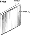
図9は、前記第1の実施形態に係る燃料電池を構成する第1と第2のマニホールド板に組み込まれる整流板の斜視図である。
図10は、前記第1の実施形態に係る燃料電池に温度分布がなくなった状態を示す説明図である。
図11は、本発明の第2の実施形態に係る燃料電池を構成するマニホールド板と整流板とを一体的に形成した状態の斜視説明図である。
図12は、本発明の第3の実施形態に係る燃料電池の概略斜視説明図である。
図13は、前記第3の実施形態に係る燃料電池の一部分解斜視説明図である。
図14は、前記第3の実施形態に係る燃料電池を構成するセパレータの縦断説明図である。
図15は、図12中、XV−XV線断面図である。
図16は、本発明の第4の実施態様に係る燃料電池の概略斜視説明図である。
図17は、前記第4の実施形態に係る燃料電池の一部分解斜視説明図である。
図18は、前記第4の実施形態に係る燃料電池の縦断面図である。
図19は、前記第4の実施形態に係る燃料電池を構成する酸化剤ガス用整流板のガス流路および冷却媒体用流路の説明図である。
図20は、前記第4の実施形態に係る燃料電池を構成する燃料ガス用整流板のガス流路および冷却媒体用流路の説明図である。
図21は、前記第4の実施形態に係る燃料電池を構成するセパレータの縦断説明図である。
図22は、本発明の第5の実施形態に係る燃料電池の概略斜視説明図である。
図23は、前記第5の実施形態に係る燃料電池の一部分解斜視説明図である。
図24は、図22中、XXIV−XXIV線断面図である。
図25は、第1冷却媒体の供給手段の概略説明図である。
図26は、第2冷却媒体の圧力制御手段の説明図である。
図27は、前記第2冷却媒体の別の圧力制御手段の構成図である。
図28は、図22中、XXVIII−XXVIII線断面図である。
図29は、図22中、XXIX−XXIX線断面図である。
図30は、図22中、XXX−XXX線断面図である。
図31は、従来技術に係る燃料電池セルの積層状態を示す概略説明図である。
図32は、従来技術に係る燃料電池セルの配置状態と温度分布との関係を示す斜視説明図である。
図33は、従来技術に係る燃料電池セルの配置状態と温度分布との関係を示す斜視説明図である。
発明を実施するための最良の形態
図1および図2に示すように、本発明の第1の実施形態に係る燃料電池は、基本的には、燃料電池セル20を水平方向に多数積層して構成される。該燃料電池セル20は、固体高分子電解質膜22を挟んでアノード側電極26とカソード側電極24とから構成される燃料電池構造体28を含む。燃料電池構造体28の構成については、例えば、国際公表公報W094−15377号に詳細な記載があり、本発明では、これを援用する。この場合、図1では、固体高分子電解質膜22とアノード側電極26とカソード側電極24とがそれぞれ分離構成されているが、これらを一体構成としてもよいことは言うまでもない。
図3に示すように、前記電解質膜22には、水素等の燃料ガスを1つの方向へと通過させるための長円状の孔部22aと、冷却水を通過させるための孔部22bと、酸化剤ガス、例えば、酸素ガスを通過させるための孔部22cとがその上部側に設けられ、一方、前記電解質膜22の下部側には、燃料ガスを通過させるための孔部22dと、冷却水を通過させるための孔部22eと、酸化剤ガスを通過させるための孔部22fとが設けられている。
燃料電池構造体28の両側に、第1ガスケット30と第2ガスケット32とが設けられる。第1ガスケット30は、カソード側電極24を収納するための大きな開口部34を有し、第2ガスケット32にはアノード側電極26を収納するための開口部36が画成されている。第1ガスケット30、第2ガスケット32にも同様に、燃料ガスを通過させるための孔部30a、30d、32a、32d、冷却水を通過させるための孔部30b、30e、32b、32e、酸化剤ガスを通過させるための孔部30c、30f、32c、32fがそれぞれ上端部と下端部に設けられている(図4参照)。なお、第1と第2のガスケット30、32の側部に設けられている長円は、ガスケット30、32の重量を低減させるための孔部である。
次に、前記第1ガスケット30、第2ガスケット32が当接するとともに、その一部にアノード側電極26、カソード側電極24を収納する孔部が画成されたセパレータ40について説明する。
セパレータ40は、基本的には、第1マニホールド板42と、この第1マニホールド板42に当接する第1面圧発生板44と、第2面圧発生板46と、前記第1面圧発生板44と前記第2面圧発生板46との間で挟持されるセパレータ本体48と、前記第2面圧発生板46に当接する第2マニホールド板50とから構成される。
図5に示すように、前記第1マニホールド板42は、矩形状の平板で構成され、その右上隅角部に燃料ガスを供給するための燃料ガス供給用凹部42aが設けられ、それに隣接して冷却水を排出するための冷却水排出用孔部42bが設けられている。第1マニホールド板42の左上隅角部には、酸化剤ガスを供給するための酸化剤ガス供給用孔部42cが設けられる。この第1マニホールド板42の左下隅角部には、燃料ガスを排出するための燃料ガス排出用凹部42dが設けられ、この燃料ガス排出用凹部42dに隣接して冷却水供給用孔部42eが設けられる。第1マニホールド板42の右下隅角部には、酸化剤ガス排出用孔部42fが設けられる。燃料ガス供給用凹部42aと燃料ガス排出用凹部42dとは、開口部43によって連通状態にある。第1マニホールド板42の両側部にあって垂直方向へ延在する長円状の孔部は、該第1マニホールド板42の重量軽減用のものであり、真円状の孔部は、積層時にスタッド等を挿通するために用いられる。
図6に示すように、第1マニホールド板42と第2マニホールド板50とは、基本的に対称に構成されている。従って、第2マニホールド板50についてはその詳細な説明を省略するが、この第2マニホールド板50は、燃料ガス供給用孔部50aと、冷却水排出用孔部50bと、酸化剤ガス供給用凹部50cと、燃料ガス排出用孔部50dと、冷却水供給用孔部50eと、酸化剤ガス排出用凹部50fとを有している。酸化剤ガス供給用凹部50cと酸化剤ガス排出用凹部50fとは、開口部52によって連通状態にある。
第1マニホールド板42に当接する第1面圧発生板44について、図7を参照しながら説明する。なお、第2面圧発生板46はこの第1面圧発生板44と実質的に同一であることから、その詳細な説明を省略する。
この第1面圧発生板44は、カーボンや金属等の導電性材料で構成された平板からなり、その右上隅角部には燃料ガス供給用凹部42aと連通する燃料ガス供給用連通孔44aが設けられ、これに隣接して冷却水排出用孔部42bと連通する冷却水排出用連通孔44bが画成されている。この第1面圧発生板44の左上隅角部には、酸化剤ガス供給用孔部42cに連通する酸化剤ガス供給用連通孔44cが設けられ、前記第1面圧発生板44の左下隅角部には、第1マニホールド板42の燃料ガス排出用凹部42dと連通する燃料ガス排出用連通孔44dが、この連通孔44dに近接して冷却水供給用孔部42eに連通する冷却水供給用連通孔44eが設けられている。第1マニホールド板42の右下隅角部には、酸化剤ガス排出用孔部42fに連通する酸化剤ガス排出用連通孔44fが設けられている。前記第1面圧発生板44に画成されている残余の長円状の孔部は、その重量軽減のためのものであり、また、真円状の孔部は、燃料電池セル20を積層緊締する際のスタッド挿通用として用いられる。
図8には、第3のマニホールド板、すなわち、セパレータ本体48が示されている。このセパレータ本体48は、冷却水を供給して、燃料電池構造体28を冷却するためのものである。比較的厚めのセパレータ本体48は、カーボン材や金属板等の導電性材料で構成され、凹部42a、連通孔44aと連通する燃料ガス供給用孔部48aをその右上隅角部に有する。冷却水排出用孔部42b、連通孔44bに連通する冷却水排出用凹部48bが前記孔部48aに隣接し、かつこのセパレータ本体48の略中央上部に設けられるとともに、左上隅角部には酸化剤ガス供給用孔部42c、連通孔44cに連通する酸化剤供給用孔部48cが設けられる。左下隅角部には燃料ガス排出用凹部42d、連通孔44dに連通する孔部48dが設けられ、図8において、冷却水排出用凹部48bの直下に冷却水供給用凹部48eが設けられている。右下隅角部には、酸化剤ガス排出用孔部48fが設けられる。なお、凹部48bと凹部48eは大きく画成された開口部62によって連通状態にある。
セパレータ本体48の開口部62には、冷却水整流板70、72が嵌合固定される。冷却水整流板70、72を合わせると前記セパレータ本体48の厚さと略同じ厚さになる。冷却水整流板70は、図2において、垂直方向へと延在する複数本の並列な溝70aを有し、同様に、冷却水整流板72も平行な溝72aを複数本並設して有している。冷却水整流板70、72を合わせると、その溝70a、72aはそれぞれ大きな冷却水整流用通路を互いに画成することになり、それぞれの冷却水整流用通路は前記凹部48b、48eと連通状態を確保する。
図1、図2および図9から諒解されるように、第1マニホールド板42の開口部43に燃料ガス用整流板80が嵌合される。前記燃料ガス用整流板80の一面は平坦に構成され、他面には垂直方向へと延在する複数本の平行な溝80aが画成されている。この平行な溝80aによって燃料ガス供給用凹部42aと燃料ガス排出用凹部42dが連通する。一方、第2マニホールド板50の開口部52に酸化剤ガス用整流板82が嵌合される。前記酸化剤ガス用整流板82の一面は平坦に構成され、他面には垂直方向へと延在する複数本の平行な溝82aを画成している。この平行な溝82aによって酸化剤ガス供給用凹部50cと酸化剤ガス排出用凹部50fとが連通する。なお、第1マニホールド板42と燃料ガス用整流板80、第2マニホールド板50と酸化剤ガス用整流板82の厚さは、実質的に同一である。
このように構成されたセパレータ本体48が第1面圧発生板44、第2面圧発生板46で挟持され、さらにこれらが第1マニホールド板42、第2マニホールド板50で挟持される。第1マニホールド板42に第2ガスケット32が当接し、第2マニホールド板50に第1ガスケット30が当接し、それぞれのガスケット30、32の間に、前記のように、燃料電池構造体28が挟持され、積層された燃料電池セル20が構成される。この時、燃料電池構造体28を構成する固体高分子電解質膜22の燃料ガス供給用孔部22aと第1ガスケット30の孔部30a、第2ガスケット32の孔部32a、第1マニホールド板42の凹部42a、セパレータ本体48の孔部48aおよび第2マニホールド板50の孔部50aは、それぞれ連通状態を確保し、以下、燃料ガス排出用孔部、冷却水排出用孔部、冷却水供給用孔部、酸化剤ガス供給用孔部、酸化剤ガス排出用孔部もそれぞれ同様に連通状態を確保する。
本発明の第1の実施形態に係る燃料電池は、以上のように構成されるものであり、次にその動作について説明する。
基本的に、多数の燃料電池セル20は、互いに積層されて燃料電池を構成するわけであるが、第1の実施形態においては、積層された燃料電池セル20は水平方向へと配置される。そして、その起動にあたっては、好ましくは、水素ガスが燃料ガスとして第1マニホールド板42の凹部42a、第1面圧発生板44の連通孔44a、セパレータ本体48の孔部48a、第2面圧発生板46の連通孔46a、第2マニホールド板50の孔部50a、第1ガスケット30の孔部30a、固体高分子電解質膜22の孔部22a、第2ガスケット32の孔部32a、次段の第1マニホールド板42の凹部42aの如く通過する。
その際、第1マニホールド板42では、燃料ガスが凹部42aから整流板80の溝80aを通り、凹部42dに到達する。この間に、整流板80の溝80aを通過する燃料ガスは、アノード側電極26に到達する。前記凹部42dの未反応ガスは、第1マニホールド板42の凹部42d、第1面圧発生板44の連通孔44d、セパレータ本体48の孔部48d、第2面圧発生板46の連通孔46d、第2マニホールド板50の孔部50d、第1ガスケット30の孔部30d、固体高分子電解質膜22の孔部22d、第2ガスケット32の孔部32d、次段の第1マニホールド板42の凹部42dの如く通過する。
一方、酸化剤ガスは、第1マニホールド板42の孔部42c、第1面圧発生板44の連通孔44c、セパレータ本体48の孔部48c、第2面圧発生板46の連通孔46c、第2マニホールド板50の凹部50c、第1ガスケット30の孔部30c、固体高分子電解質膜22の孔部22c、第2ガスケット32の孔部32c、次段の第1マニホールド板42の孔部42cの如く通過する。
その際、第2マニホールド板50では、酸化剤ガスが凹部50cから整流板82の溝82aを通り、凹部50fに到達する。この間に、整流板82の溝82aを通過する酸化剤ガスはカソード側電極24に到達する。前記凹部50fの酸化剤ガスは、第1マニホールド板42の孔部42f、第1面圧発生板44の連通孔44f、セパレータ本体48の孔部48f、第2面圧発生板46の連通孔46f、第2マニホールド板50の凹部50f、第1ガスケット30の孔部30f、固体高分子電解質膜22の孔部22f、第2ガスケット32の孔部32f、次段の第1マニホールド板42の孔部42fの如く通過する。
これに対して、冷却水は、燃料ガス、酸化剤ガスとは反対方向から供給される。すなわち、第1マニホールド板42の孔部42eを通過した冷却水は、第2ガスケット32の孔部32e、固体高分子電解質膜22の孔部22e、第1ガスケット30の孔部30e、第2マニホールド板50の孔部50e、第2面圧発生板46の連通孔46e、セパレータ本体48の凹部48e、第1面圧発生板44の連通孔44e、第1マニホールド板42の孔部42eの如く通過する。この間に、整流板70と72とが互いに接合されることによって画成される冷却水整流用通路を下方から上方へと通過する冷却水は、セパレータ本体48の凹部48bに至る。このように、上昇して前記凹部48bに至った冷却水は、第1面圧発生板44の連通孔44b、第1マニホールド板42の孔部42b、第2ガスケット32の孔部32b、固体高分子電解質膜22の孔部22b、第1ガスケット30の孔部30b、第2マニホールド板50の孔部50b、第2面圧発生板46の連通孔46bの如く流れる。
すなわち、第1の実施形態では、燃料ガスと酸化剤ガスとが重力方向に沿って上から下へとそれぞれ流れる一方、冷却水がセパレータ本体48を下から上へと流れるに至る。結局、図10に示すように、最も低い温度の冷却水で燃料電池セル20の最も温度の高くなる部位を冷却する原理を採用し、冷却水は、そのセパレータ本体48に導入する際に十分な冷却能力を有している地点で、通常、温度勾配が高くなる電解質膜22の下部を強制的に冷却する。従って、全体として温度分布のない状態で燃料電池セル20が稼働されることになる。この結果、全体的にセル面内の温度は下がり、冷却水の入口付近に比べて出口付近での熱が取り去られ、その温度は低下するに至るが、ガス出口側付近の熱で温められた冷却水によってガス入口付近の燃料電池セル20の温度が上昇し、ガスの入口側と出口側付近の燃料電池セル20における温度差は実質的に小さくなる。よって、温度分布が少ない状態で燃料電池セル20の作動が可能となる。
図11に、本発明を実施する第2の実施形態示す。前記第1の実施形態では、第1マニホールド板42と整流板80とが分離構成され、同様に、第2マニホールド板50と整流板82とが分離構成されている。しかしながら、この第2の実施形態では、前記第1マニホールド板42と整流板80、第2マニホールド板50と整流板82とを一体形成して整流機構付マニホールド板90としているため、製造が容易になり、かつ部品点数が少なくなる利点がある。
次に、本発明の第3の実施形態に係る燃料電池について説明する。
図12および図13において、参照数字110は、第3の実施形態に係る燃料電池を示す。この燃料電池110は、固体高分子電解質膜112を挟んでカソード側電極114とアノード側電極116を対設した燃料電池構造体118と、3組の前記燃料電池構造体118を挟持するセパレータ120とを備える。燃料電池構造体118とセパレータ120は、一対のエンドプレート122a、122bおよびタイロッド124により一体的に固定される(図12参照)。
図13に示すように、電解質膜112の上部側には、燃料ガス導入用孔部112aと冷却媒体排出用孔部112bと酸化剤ガス導入用孔部112cとが設けられる一方、この電解質膜112の下部側には、燃料ガス排出用孔部112dと冷却媒体導入用孔部112eと酸化剤ガス排出用孔部112fとが設けられる。
燃料電池構造体118の両側には、第1および第2ガスケット130、132が配設される。第1ガスケット130は、カソード側電極114を収容するための大きな開口部134を有し、第2ガスケット132は、アノード側電極116を収容するための大きな開口部136を有する。第1および第2ガスケット130、132は、燃料ガス導入用孔部130a、132aと冷却媒体排出用孔部130b、132bと酸化剤ガス導入用孔部130c、132cとをそれぞれ上部側に設けるとともに、燃料ガス排出用孔部130d、132dと冷却媒体導入用孔部130e、132eと酸化剤ガス排出用孔部130f、132fとをそれぞれ下部側に設ける。
セパレータ120は、第1セパレータ部(カソード側要素部材)140と第2セパレータ部(アノード側要素部材)142とを備える。
第1セパレータ部140を構成する第1マニホールド板146は、矩形状の平板で構成され、その中央部に大きな開口部148を有する。第1マニホールド板146の上部側には、燃料ガス導入用孔部146aと冷却媒体排出用孔部146bと酸化剤ガス導入用孔部146cとが設けられ、その下部側には、燃料ガス排出用孔部146dと冷却媒体導入用孔部146eと酸化剤ガス排出用孔部146fとが設けられる。孔部146c、146fは、第1マニホールド板146の一方の面部(カソード側電極114側)に互いに対角の位置に対応して設けられた凹部147a、147bを介して開口部148に連通する。
第1マニホールド板146の開口部148に酸化剤ガス用整流板150が嵌合される。酸化剤ガス用整流板150は、図13および図14に示すように、その一面側(カソード側電極114側)に水平方向に複数の突起150aが互いに平行しかつ千鳥状に設けられ、これにより、鉛直方向に向かって蛇行する酸化剤ガス用通路150bが形成される。この酸化剤ガス用整流板150の他方の面部(後述する冷却媒体用流路を形成する面部)には、冷却媒体との接触面積を拡大するための複数、例えば、11個の熱交換用フィン(接触面積拡大部位)150cが水平方向に互いに平行に突出形成される。
第2セパレータ部142は、上記第1セパレータ部140と同様に構成されており、第2マニホールド板152とこの第2マニホールド板152の開口部154に嵌合する燃料ガス用整流板156とを備える。
第2マニホールド板152は、その上部側に燃料ガス導入用孔部152aと冷却媒体排出用孔部152bと酸化剤ガス導入用孔部152cとが設けられる一方、その下部側に燃料ガス排出用孔部152dと冷却媒体導入用孔部152eと酸化剤ガス排出用孔部152fとが設けられる。孔部152a、152dは、第2マニホールド板152の一方の面部(第1セパレータ部140と反対側の面部)に設けられた凹部153a、153bを介して開口部154に連通する。孔部152b、152eは、第2マニホールド板152の他方の面部(第1セパレータ部140側の面部)に設けられた切欠152g、152hを介して開口部154に開放される。
燃料ガス用整流板156は、図13および図14に示すように、一方の面に水平方向に平行しかつ千鳥状に配設された複数の突起156aを介して鉛直方向に蛇行する燃料ガス用通路156bが形成されるとともに、その反対側の面部(後述する冷却媒体用流路側の面部)には、冷却媒体との接触面積を拡大するための複数、例えば、3個の熱交換用フィン(接触面積拡大部位)156cが突出形成される。
酸化剤ガス用整流板150および燃料ガス用整流板156は、炭素、ステンレス鋼またはインコネル(商標名)等のニッケル系合金等の耐蝕性を有する導電性金属、導電性ゴム、導電性樹脂等、またはこれらを組み合わせた材料で構成される。
セパレータ120は、図14に示すように、第1および第2セパレータ部140、142が一体的に組み付けられる際、酸化剤ガス用整流板150と燃料ガス用整流板156の間に冷却媒体用流路158が形成される。この流路158は、第2マニホールド板152に設けられた切欠152g、152hを介し孔部152b、152eに連通する(図15参照)。
なお、第2マニホールド板152に切欠152g、152hを設ける代わりに、第1マニホールド板146に孔部146b、146eを互いに連通する切欠を設けてもよく、また、この第1および第2マニホールド板146、152の双方に切欠を設けてもよい。
このように構成される燃料電池110の動作について、以下に説明する。
燃料ガス(水素ガス)が燃料電池110に供給されると、この燃料ガスは、第1セパレータ部140を構成する第1マニホールド板146の孔部146aおよび第2セパレータ部142を構成する第2マニホールド板152の孔部152aに導入され、その一部がこの孔部152aから燃料ガス用整流板156の通路156bに供給される。
燃料電池110に供給される酸化剤ガス(空気)は、第1マニホールド板146の孔部146cおよび第2マニホールド板152の孔部152cに導入され、その一部がこの孔部146cから酸化剤ガス用整流板150の通路150bに供給される。これにより、燃料電池構造体118を構成するアノード側電極116側に燃料ガスが供給されるとともに、カソード側電極114側に酸化剤ガスが供給され、この燃料電池構造体118に電気エネルギが生成される。
一方、図15に示すように、燃料電池110の下部側に冷却媒体が供給される。この冷却媒体としては、水、メタノール、水とメタノールの混合溶液、燃料電池作動用ガス(使用前または使用後)、または燃料電池110の作動温度以下の沸点を有する物質である。
具体的には、無機化合物である水(100℃)、アンモニア(−33.43℃)、二酸化炭素(−78.5℃)、アルゴン(−185.869℃)および窒素(−195.8℃)と、有機化合物であるメタノール(64.51℃)、エタノール(78.3℃)およびイソプロパノール(82.33℃)等のアルコール類と、アセトアルデヒド(20.4℃)、アセトン(56.12℃)、エチルメチルケトン(79.59℃)およびホルムアルデヒド(−19.1℃)等のアルデヒド・ケトン類と、エチルプロピルエーテル(63.86℃)、エチルメチルエーテル(7.35℃)、ジエチルエーテル(34.55℃)、ジメチルエーテル(−24.84℃)およびジイソプロピルエーテル(68.27℃)等のエーテル類と、メタン(−161.49℃)、エタン(−88.63℃)、プロパン(−42.07℃)、ブタン(−0.5℃)、ペンタン(36.07℃)、イソペンタン(27.85℃)、ヘキサン(68.74℃)およびイソヘキサン(60.27℃)等の飽和炭化水素と、蟻酸メチル(31.76℃)、蟻酸エチル(57℃)、酢酸エチル(77.17℃)、酢酸ビニル(72.92℃)および酢酸メチル(57℃)等のエステルと、シクロブタン(12.51℃)、シクロプロパン(−32.87℃)、シクロヘキサン(80.74℃)、シクロペンタン(49.26℃)、ヘキサフルオロベンゼン(80.26℃)およびベルフルホロシクロヘキサン(52.52℃)等の環状化合物とが使用される。なお、上記()内は、それぞれの物質の常圧下における沸点を示す。
燃料電池110の下部側に供給された冷却媒体は、第2マニホールド板152の孔部152e、切欠152hを介して燃料ガス用整流板156と酸化剤ガス用整流板150の間に形成された流路158に導入され、この流路158を下方から上方に向かって流動する。そして、この冷却媒体は、第2マニホールド板152の上部側に設けられた孔部152bおよび第1マニホールド板146の孔部146b等を通って燃料電池110から排出される。
この場合、第3の実施形態では、第1および第2セパレータ部140、142によりセパレータ120が構成され、一面に酸化剤ガス用通路150bが設けられた酸化剤ガス用整流板150と一面に燃料ガス用通路156bが設けられた燃料ガス用整流板156との間に、冷却媒体用流路158が直接形成されている。このため、冷却媒体を流通させるために専用の冷却板を用いるものに比べ、部品数が一挙に削減されてセパレータ120全体の軽量化およびコンパクト化が容易に達成されるという効果が得られる。
さらに、第3の実施形態では、酸化剤ガス用整流板150に流路158側に突出して複数のフィン150cが設けられる一方、燃料ガス用整流板156にこの流路158側に突出して複数のフィン156cが設けられており、カソード側電極114およびアノード側電極116の冷却効率を容易に向上させることができる。
しかも、フィン150c、156cの形状、寸法および数等をそれぞれ個別に設定することができ、これによってカソード側電極114およびアノード側電極116の機能等に応じてこのカソード側電極114およびこのアノード側電極116に最適な冷却効率を確実に選択することができる。
すなわち、カソード側電極114側では、燃料電池110の反応によりこのカソード側電極114側で発生する熱を除去して該カソード側電極114中のイオン導電成分の乾燥および電解質膜112のカソード側電極114側の乾燥を防ぐとともに、酸化剤ガスを加湿する場合に前記カソード側電極114中のイオン導電成分および電解質膜112のカソード側電極114側へ水が入り易いようにカソード側電極114側の冷却効率が設定される。一方、アノード側電極116側では、燃料ガスを加湿する場合にアノード側電極116中のイオン導電成分および電解質膜112のアノード側電極116側へ水が入り易いように該アノード側電極116側の冷却効率が設定される。
従って、カソード側電極114とアノード側電極116では、それぞれの冷却効率が異なる場合が多く、これらの冷却効率の違いに対応してフィン150cとフィン156cの形状、寸法および数を異ならせている。これにより、カソード側電極114およびアノード側電極116において、それぞれの冷却効率を個別にかつ最適な状態に設定することが可能になるという効果が得られる。
さらに、第3の実施形態では、酸化剤ガス用整流板150のフィン150cおよび燃料ガス用整流板156のフィン156cが冷却媒体にのみ接しており、カソード側電極114−アノード側電極116間の熱伝導が固体高分子電解質膜12を介してのみ行われる。従って、セパレータ20を介した熱伝導が遮断されるため、選択的冷却効率はさらに高まる。
なお、第3の実施形態では、接触面積拡大部位としてフィン150c、156cを用いたが、これに限定されるものではなく、冷却媒体との接触面積を拡大し得る構造であれば、凹状部や種々の変形面等を採用することが可能である。
次に、本発明の第4の実施態様に係る燃料電池について説明する。
図16〜図18において、参照数字210は、第4の実施形態に係る燃料電池を示す。この燃料電池210は、固体高分子電解質膜212を挟んでカソード側電極214とアノード側電極216を対設した燃料電池構造体218と、この燃料電池構造体218を挟持するセパレータ220とを備える。燃料電池構造体218とセパレータ220は、一対のエンドプレート222a、222bおよびタイロッド224により一体的に固定される。
燃料電池構造体218を構成する固体高分子電解質膜212の上部側には、冷却媒体(温調媒体)排出用孔部212aと酸化剤ガス導入用孔部212bと燃料ガス導入用孔部212cとが設けられる一方、その下部側には、燃料ガス排出用孔部212dと酸化剤ガス排出用孔部212eと冷却媒体導入用孔部212fとが設けられる。
電解質膜212の両側には、第1および第2ガスケット230、232が設けられる。第1ガスケット230は、カソード側電極214を収容するための大きな開口部234を有し、第2ガスケット232は、アノード側電極216を収容するための大きな開口部236を有する。第1および第2ガスケット230、232の上部側には、冷却媒体排出用孔部230a、232aと酸化剤ガス導入用孔部230b、232bと燃料ガス導入用孔部230c、232cとが設けられる一方、これらの下部側には、燃料ガス排出用孔部230d、232dと酸化剤ガス排出用孔部230e、232eと冷却媒体導入用孔部230f、232fとが設けられる。
セパレータ220は、カソード側電極214側に当接する第1セパレータ部240と、アノード側電極216側に当接する第2セパレータ部242と、この第1および第2セパレータ部240、242に挟持される仕切板(隔壁)244とを備える。
第1セパレータ部240は、第1マニホールド板246とこの第1マニホールド板246に形成された比較的大きな開口部248に嵌合する酸化剤ガス用整流板250とを有する。
第1マニホールド板246は、緻密質カーボンで形成された矩形状平板であり、その上部側には、冷却媒体排出用孔部246aと酸化剤ガス導入用孔部246bと燃料ガス導入用孔部246cとが設けられる。第1マニホールド板246の下部側には、燃料ガス排出用孔部246dと酸化剤ガス排出用孔部246eと冷却媒体導入用孔部246fとが設けられる。
孔部246b、246eは、第1マニホールド板246の一方(カソード側電極214側)の面部に形成された切欠247a、247bを介して開口部248に連通する一方、孔部246a、246fは、この第1マニホールド板246の他方の面部に形成された切欠247c、247dを介して前記開口部248に連通する(図17および図19参照)。
酸化剤ガス用整流板250は、炭素、ステンレス鋼、またはインコネル(商標名)等のニッケル系合金等の耐蝕性を有する導電性金属、導電性ゴムまたは導電性樹脂およびそれらを組み合わせた材料で構成される。酸化剤ガス用整流板250の一面部には、水平方向に延在して互いに平行しかつ千鳥状に配置された複数の突起部250aが設けられ、これらの突起部250aによって鉛直方向に向かって蛇行する第1ガス流路250bが形成される(図19参照)。この酸化剤ガス用整流板250の他方の面部には、同様に、複数の突起部250cが水平方向に対して互いに平行しかつ千鳥状に設けられることにより、第1ガス流路250bと同一の流路構造を有する第1冷却媒体用流路(温調媒体用流路)250dが形成される。
第2セパレータ部242は、第2マニホールド板252とこの第2マニホールド板252の中央に形成された比較的大きな開口部254に嵌合する燃料ガス用整流板256とを有する。第2マニホールド板252は、第1マニホールド板246と同様に構成されており、その上部側には、冷却媒体排出用孔部252aと酸化剤ガス導入用孔部252bと燃料ガス導入用孔部252cとが設けられる一方、その下部側には、燃料ガス排出用孔部252dと酸化剤ガス排出用孔部252eと冷却媒体導入用孔部252fとが設けられる。
孔部252a、252fは、第2マニホールド板252の一方(第1セパレータ部240側)の面部に形成された切欠258a、258bを介して開口部254に連通し、孔部252c、252dは、この第2マニホールド板252の他方の面部に形成された切欠258c、258dを介して前記開口部254に連通する(図17および図20参照)。
燃料ガス用整流板256は、水透過性カーボン材で形成されている。この燃料ガス用整流板256の一方の面部には、水平方向に延在して互いに平行しかつ千鳥状に配置された複数の突起部256aにより第2ガス流路256bが形成される。この燃料ガス用整流板256の他方の面部には、同様に、水平方向に延在して互いに平行しかつ千鳥状に配置された複数の突起部256cを介して第2冷却媒体用流路(温調媒体用流路)256dが形成される。第2ガス流路256bと第2冷却媒体用流路256dは、互いに同一の流路構造を有するとともに、互いに反対方向の流れ方向に設定されている(図20参照)。
図21に示すように、第1ガス流路250bの開口断面積および第1冷却媒体用流路250dの開口断面積は、第2ガス流路256bの開口断面積および第2冷却媒体用流路256dの開口断面積よりも大きく設定されている。
仕切板244は、緻密質カーボン材で形成された板状を有しており、その上部側には、冷却媒体排出用孔部244aと酸化剤ガス導入用孔部244bと燃料ガス導入用孔部244cとが設けられる。この仕切板244の下部側には、燃料ガス排出用孔部244dと酸化剤ガス排出用孔部244eと冷却媒体導入用孔部244fとが設けられる。
このように構成される燃料電池210の動作について、以下に説明する。
燃料ガス(水素ガス)が燃料電池210に供給されると、この燃料ガスは、第1セパレータ部240を構成する第1マニホールド板246の孔部246c、仕切板244の孔部244cおよび第2セパレータ部242を構成する第2マニホールド板252の孔部252cに供給されるとともに、この孔部252cの切欠258cから燃料ガス用整流板256の第2ガス流路256bに導入される(図20参照)。このため、燃料ガスは、第2ガス流路256bに沿って蛇行するように重力方向に流れ、切欠258dから孔部252dに排出される。
酸化剤ガスが燃料電池210に供給されると、この酸化剤ガスは、第1マニホールド板246の孔部246b、仕切板244の孔部244bおよび第2マニホールド板252の孔部252bに供給されるとともに、この孔部246bに連通する切欠247aを介して酸化剤ガス用整流板250の第1ガス流路250bに導入される。従って、酸化剤ガスは、図19に示すように、第1ガス流路250bに沿って蛇行するように重力方向に流れ、孔部246eから排出される。これにより、燃料電池構造体218を構成するアノード側電極216に燃料ガスが供給されるとともに、カソード側電極214に酸化剤ガスが供給される。
一方、燃料電池210に供給される冷却媒体は、水、メタノール、または水とメタノールの混合溶液であり、この冷却媒体が第1マニホールド板246の孔部246fに供給されると、その一部が切欠247dから酸化剤ガス用整流板250の第1冷却媒体用流路250dに導入される。このため、冷却媒体は、図19に示すように、酸化剤ガス用整流板250の第1冷却媒体用流路250dに沿って蛇行するように重力方向とは逆方向に流れ、第1マニホールド板246の孔部246aに排出される。
また、第2マニホールド板252の孔部252fに導入された冷却媒体の一部は、切欠258bから燃料ガス用整流板256の第2冷却媒体用流路256dに導入される。従って、図20に示すように、冷却媒体は、燃料ガス用整流板256の第2冷却媒体用流路256dに沿って蛇行するように重力方向とは逆方向に流れ、第2マニホールド板252の孔部252aに排出される。
この場合、第4の実施形態では、図19に示すように、酸化剤ガス用整流板250の一方の面部に酸化剤ガスを重力方向に向かって蛇行するように流動させる第1ガス流路250bが設けられるとともに、この酸化剤ガス用整流板250の他方の面部には、前記第1ガス流路250bと表裏同一の流路構造でかつ冷却媒体を重力方向とは逆方向に流動させる第1冷却媒体用流路250dが設けられている。
すなわち、酸化剤ガスは、第1ガス流路250bの入口側(孔部246b側)に比べ出口側(孔部246e側)が最も高温となっている。このため、酸化剤ガスの温度が高温になる孔部246e側に対応する孔部246f側から冷却媒体が導入されることにより、前記冷却媒体と前記酸化剤ガスの間の熱交換効率が一挙に向上し、該酸化剤ガスは、第1ガス流路250bの入口側から出口側にわたり全体的に温度差のない状態に確実に温度調整され、発電部の温度均一化が容易に遂行されるという効果が得られる。
一方、燃料ガス用整流板256においても同様に、図20に示すように、第2ガス流路256bに沿って重力方向に流れる燃料ガスと、第2冷却媒体用流路256dに沿って重力方向と反対方向に流れる冷却媒体とは、表裏同一の流路を互いに反対方向に流れている。従って、燃料ガスが入口側から出口側に至る間の温度差を少なくし、発電部の温度均一化が図られるという利点が得られる。
さらに、第4の実施形態では、第1ガス流路250bおよび第1冷却媒体用流路250dの開口面積が、第2ガス流路256bおよび第2冷却媒体用流路256dの開口断面積よりも大きく設定されている。すなわち、燃料ガスと酸化剤ガスは、例えば、メタノールの改質ガスと空気、水素ガスと空気、または水素ガスと酸素ガスの組み合わせからなるため、それぞれの粘性が異なる。このため、燃料ガスと酸化剤ガスとを同一のガス流路断面積に対し同一流量ずつ流すと、酸化剤ガス側で燃料ガス側より高いヘッド圧が発生してしまう。これにより、極間差圧が生じて固体高分子電解質膜212が破損したり、酸化剤ガス供給源の負荷が大きくなってしまうという問題が生じる。
また、燃料ガスおよび酸化剤ガスとして改質ガスおよび空気を使用する場合、燃料利用率と空気利用率に起因して燃料ガスと空気の流量減少に差異が発生し、空気の流量減少が前記燃料ガスの流量減少に比べて小さいものとなる。
この結果、酸化剤ガス側の第1ガス流路250bの開口断面積を燃料ガス側の第2ガス流路256b側の開口断面積よりも大きくする必要がある。
さらにまた、カソード側電極214側では、反応生成水が酸化剤ガス用整流板250の壁面に凝集結露する場合がある。このため、第1ガス流路250bの開口断面積が第2ガス流路256bの開口断面積よりも大きく設定されることにより、結露した凝縮水によるガス流路閉塞、およびそれに起因する脈動流(スラグ流等)を防ぎ、酸化剤ガスが流れ易くなってガス排気効率が保たれる。
なお、第4の実施形態では、温調媒体として冷却媒体を使用し、酸化剤ガスおよび燃料ガスを均一に冷却する場合について説明したが、これとは逆に、加熱媒体を用いて前記酸化剤ガスおよび前記燃料ガスを全体として均一な温度に加熱することも可能である。
次いで、本発明の第5の実施形態に係る燃料電池について説明する。
図22〜図24において、参照数字310は、第5の実施形態に係る燃料電池を示す。この燃料電池310は、固体高分子電解質膜312を挟んでカソード側電極314とアノード側電極316を対設した燃料電池構造体318と、3組の前記燃料電池構造体318を挟持するセパレータ320とを備える。燃料電池構造体318とセパレータ320は、一対のエンドプレート322a、322bおよび4本のタイロッド324により一体的に固定される。
図23に示すように、電解質膜312の上部側には、燃料ガス導入用孔部312aとカソード側電極冷却媒体(第2冷却媒体)排出用孔部312bと冷却水(第1冷却媒体)排出用孔部312cと酸化剤ガス導入用孔部312dとが設けられる。電解質膜312の下部側には、燃料ガス排出用孔部312eとカソード側電極冷却媒体導入用孔部312fと冷却水導入用孔部312gと酸化剤ガス排出用孔部312hとが設けられる。
燃料電池構造体318の両側には、第1ガスケット330と第2ガスケット332とが配設される。第1ガスケット330は、カソード側電極314を収容するための大きな開口部334を有し、第2ガスケット332は、アノード側電極316を収容するための大きな開口部336を有する。第1および第2ガスケット330、332は、燃料ガス導入用孔部330a、332aとカソード側電極冷却媒体排出用孔部330b、332bと冷却水排出用孔部330c、332cと酸化剤ガス導入用孔部330d、332dとをそれぞれ上部側に設けるとともに、燃料ガス排出用孔部330e、332eとカソード側電極冷却媒体導入用孔部330f、332fと冷却水導入用孔部330g、332gと酸化剤ガス排出用孔部330h、332hとをそれぞれ下部側に設ける。
セパレータ320は、第1セパレータ部340と、第2セパレータ部342と、この第1および第2セパレータ部340、342に挟持される仕切板344とを備える。
第1セパレータ部340を構成する第1マニホールド板346は、矩形状の平板で構成され、その中央部に大きな開口部348を有する。第1マニホールド板346の上部側には、燃料ガス導入用孔部346aとカソード側電極冷却媒体排出用孔部346bと冷却水排出用孔部346cと酸化剤ガス導入用孔部346dとが設けられる。第1マニホールド板346の下部側には、燃料ガス排出用孔部346eとカソード側電極冷却媒体導入用孔部346fと冷却水導入用孔部346gと酸化剤ガス排出用孔部346hとが設けられる。互いに対向角の位置に設けられた孔部346dと孔部346hには、カソード側電極314側に偏位して第1マニホールド板346に設けられた凹部347a、347bが連通し、この凹部347a、347bが開口部348を介して連通状態にある(図23、図24および図28参照)。
第1マニホールド板346の開口部348に酸化剤ガス用整流板(カソード側要素部材)350が嵌合される。酸化剤ガス用整流板350は、その一面が平坦でかつ他面が鉛直方向に向かって蛇行する通路350aが形成され、この通路350aに孔部346dと孔部346hが連通する。酸化剤ガス用整流板350は、緻密質材料、具体的には、黒鉛化炭素、ステンレス鋼、またはインコネル(商標名)等のニッケル系合金等の耐蝕性を有する導電性金属、導電性ゴム、または導電性樹脂で構成されている。
第1マニホールド板346の孔部346b、346fは、第2セパレータ部342側に偏位して設けられた凹部349a、349bおよび開口部348を介して互いに連通する(図23、図29および図30参照)。
第2セパレータ部342は、上記第1セパレータ部340と同様に構成されており、第2マニホールド板352と、この第2マニホールド板352の開口部354に嵌合する燃料ガス用整流板(アノード側要素部材)356とを有する。
第2マニホールド板352の上部側には、燃料ガス導入用孔部352aとカソード側電極冷却媒体排出用孔部352bと冷却水排出用孔部352cと酸化剤ガス導入用孔部352dとが設けられる一方、その下部側には、燃料ガス排出用孔部352eとカソード側電極冷却媒体導入用孔部352fと冷却水導入用孔部352gと酸化剤ガス排出用孔部352hとが設けられる。孔部352a、352eは、凹部358a、358bを介して開口部354に連通するとともに(図23、図24および図28参照)、孔部352c、352gは、凹部358c、358dを介して前記開口部354に連通する(図23、図29および図30参照)。
燃料ガス用整流板356は、その一面が平坦でかつ他面が鉛直方向に向かって蛇行する通路356aが形成される。この燃料ガス用整流板356は、その平坦面側に供給される水分(第1冷却媒体)をアノード側電極316側に供給するために、導電性の水透過性材料で形成され、具体的には、多孔質炭素焼結体、導電性多孔質焼結金属、多孔質導電性ゴム、多孔質導電性樹脂等の多孔質体、またはこれらを組み合わせた材料で構成される。燃料ガス用整流板356が多孔質炭素焼結体で形成される際、水の滴下を阻止すべくその気孔率が70%以下でかつポア径が40μm以下の多孔性を有することが望ましい。
なお、燃料ガス用整流板356は、好適には、耐久性を向上させるために撥水化処理された多孔質体で構成される。この場合、燃料ガス用整流板356は、所定濃度に調整されたPTFE(ポリテトラフルオロエチレン)の分散液に浸漬した後、室温で乾燥させ、次いで、300〜350℃で焼成することにより、撥水化処理が行われる。
仕切板344は、緻密質かつ導電性を有する黒鉛化炭化、ステンレス鋼、またはニッケル系合金等の耐蝕性の導電性金属、導電性ゴム、導電性樹脂、またはこれらを組み合わせた材料で構成される。この仕切板344の上部側には、燃料ガス導入用孔部344aとカソード側電極冷却媒体排出用孔部344bと冷却水排出用孔部344cと酸化剤ガス導入用孔部344dとが設けられる一方、その下部側には、燃料ガス排出用孔部344eとカソード側電極冷却媒体導入用孔部344fと冷却水導入用孔部344gと酸化剤ガス排出用孔部344hとが設けられる。
図24に示すように、セパレータ320は、燃料ガス用整流板356と仕切板344の間にアノード側電極316側を冷却するための冷却水が導入される第1冷却通路360を有するとともに、酸化剤ガス用整流板350と前記仕切板344の間にカソード側電極314側を冷却するための第2冷却媒体が導入される第2冷却通路362を設ける。
第1および第2冷却通路360、362は、それぞれ独立しており、この第1冷却通路360に第1冷却媒体である水が供給される。一方、第2冷却通路362には、燃料電池310の作動温度近傍以下の沸点温度を有する少なくとも一種以上の物質であって、これらの物質は相互の反応および該物質が接する酸化剤ガス用整流板350および仕切板344との反応を起こさない物質である第2冷却媒体が供給される。
具体的には、無機化合物である水(100℃)、アンモニア(−33.43℃)、二酸化炭素(−78.5℃)、アルゴン(−185.869℃)および窒素(−195.8℃)と、有機化合物であるメタノール(64.51℃)、エタノール(78.3℃)およびイソプロパノール(82.33℃)等のアルコール類と、アセトアルデヒド(20.4℃)、アセトン(56.12℃)、エチルメチルケトン(79.59℃)およびホルムアルデヒド(−19.1℃)等のアルデヒド・ケトン類と、エチルプロピルエーテル(63.86℃)、エチルメチルエーテル(7.35℃)、ジエチルエーテル(34.55℃)、ジメチルエーテル(−24.84℃)およびジイソプロピルエーテル(68.27℃)等のエーテル類と、メタン(−161.49℃)、エタン(−88.63℃)、プロパン(−42.07℃)、ブタン(−0.5℃)、ペンタン(36.07℃)、イソペンタン(27.85℃)、ヘキサン(68.74℃)およびイソヘキサン(60.27℃)等の飽和炭化水素と、蟻酸メチル(31.76℃)、蟻酸エチル(57℃)、酢酸エチル(77.17℃)、酢酸ビニル(72.92℃)および酢酸メチル(57℃)等のエステルと、シクロブタン(12.51℃)、シクロプロパン(−32.87℃)、シクロヘキサン(80.74℃)、シクロペンタン(49.26℃)、ヘキサフルオロベンゼン(80.26℃)およびベルフルホロシクロヘキサン(52.52℃)等の環状化合物とが使用される。なお、上記()内は、それぞれの物質の常圧下における沸点温度を示す。
第1冷却通路360に水を供給するための水供給構造が、図25に示されている。この水供給構造は、水タンク370を備え、この水タンク370と燃料電池310が循環路372により連通している。この循環路372上には、水タンク370から燃料電池310に水を供給するための水供給循環用ポンプ374が配設されるとともに、この燃料電池310の排出側には背圧弁376、ラジエータ375、冷却フアン377およびイオン交換樹脂378が配設されている。
第2冷却通路362に供給される第2冷却媒体による締め付け圧を制御するために、図26に示す圧力制御手段380と、図27に示す圧力制御手段390とが、選択的に設けられている。圧力制御手段380は、第2冷却通路362に導入される第2冷却媒体の沸点温度が燃料電池310の作動温度に近く、かつこの第2冷却媒体による蒸気圧が不足する場合に使用されるものであり、前記燃料電池310と循環路382を介して連通する冷媒タンク384を備えるとともに、この循環路382に昇圧ポンプ386と背圧弁388が配設されている。
圧力制御手段390は、第2冷却通路362に導入される第2冷却媒体の沸点が燃料電池310の作動温度よりも低く、かつこの第2冷却媒体の蒸気圧が十分に得られる場合に採用されるものであり、前記燃料電池310の外部に設けられた循環路392に配設され、前記冷却媒体を加熱または冷却するための温度調整器394を備えている。
このように構成される燃料電池310の動作について、以下に説明する。
図24に示すように、燃料ガス(水素ガス)が燃料電池310に供給されると、この燃料ガスは第1セパレータ部340を構成する第1マニホールド板346の孔部346a、燃料電池構造体318の孔部330a、312aおよび332aを通って第2セパレータ部342を構成する第2マニホールド板352の孔部352aに至る。燃料ガスは、孔部352aおよび凹部358aから燃料ガス用整流板356の通路356aを通って燃料電池構造体318を構成するアノード側電極316に供給され、凹部358bに排出される。
図28に示すように、酸化剤ガスは、第1マニホールド板346の孔部346dに供給され、この孔部346dおよび凹部347aから酸化剤ガス用整流板350の通路350aに導入され、燃料電池構造体318を構成するカソード側電極314に供給される。なお、未使用の酸化剤ガスは、図24に示すように、第1マニホールド板346の孔部346h等を介して外部に排出され、未使用の燃料ガスは、図28に示すように、第2マニホールド板352の孔部352e等を介して外部に排出される。
一方、第1冷却媒体である水は、図25に示すように、ポンプ374の作用下に水タンク370から循環路372を介して燃料電池310内に供給される。この水は、図30に示すように、第1セパレータ部340の孔部346g、燃料電池構造体318の孔部330g、312gおよび332gから第2セパレータ部342の孔部352gに至り、この孔部352gに連通する凹部358dから仕切板344と燃料ガス用整流板356の間、すなわち、第1冷却通路360に導入され、この第1冷却通路360を下方から上方に向かって流動する。
その際、燃料ガス用整流板356は、水透過性材料(多孔質体)で形成されており、第1冷却通路360に導入された水は、燃料ガス用整流板356を透過して通路356aに供給された燃料ガスおよびアノード側電極316を直接加湿することができる。
また、第2冷却媒体は、圧力制御手段380または圧力制御手段390を介して燃料電池310に供給される。この第2冷却媒体は、図29に示すように、第1セパレータ部340の孔部346fに供給されると、これに連通する凹部349bからセパレータ320の第2冷却通路362に下方から上方に向かって導入される。
この第2冷却通路362を構成する酸化剤ガス用整流板350は、緻密質材料で形成されており、さらに前記第2冷却通路362と第1冷却通路360が仕切板344により完全に独立している。従って、第2冷却通路362に導入された第2冷却媒体の蒸気圧あるいはこの第2冷却媒体自体の圧力により、酸化剤ガス用整流板350がカソード側電極314側に押圧され、燃料電池構造体318に所望の締め付け力が発生する。これにより、燃料電池構造体318内での接触抵抗が低減され、端子電圧の低下を確実に防止することが可能になる。
この際、異なった沸点を有する複数の冷却媒体を導入し、その割合と量を調整することにより、作動温度における押圧力を自在に設定することができる。
このように、第5の実施形態では、セパレータ320が第1および第2セパレータ部340、342とこれらの間に介装される仕切板344とを備えるとともに、この仕切板344を挟んで第1および第2冷却通路360、362が独立して形成される。このため、第1および第2冷却通路360、362には、それぞれアノード側電極316およびカソード側電極314に対応した所望の第1および第2冷却媒体を選択的に供給することができる。
特に、水透過性材料で形成された燃料ガス用整流板356の第1冷却通路360に第1冷却媒体として水が供給される一方、緻密質材料で形成された酸化剤ガス用整流板350の第2冷却通路362に所望の圧力を発生させ得る第2冷却媒体が供給される。これにより、第1冷却通路360に導入された水により燃料ガスおよびアノード側電極316側を直接加湿するとともに、第2冷却通路362に導入された第2冷却媒体により燃料電池構造体318に所定の締め付け力を付与することが可能になる。
従って、セパレータ320は、燃料ガスと酸化剤ガスを分離供給する機能と燃料電池構造体318の内部抵抗による熱を除去する機能の他に、燃料ガスが供給されるアノード側電極316を直接加湿する機能とカソード側電極314を押圧して所望の締め付け力を付与する機能をも有する。これにより、セパレータ320は、簡単な構造で多機能を有し、しかも燃料電池310全体を容易に小型化かつ軽量化することが可能になるという効果が得られる。
産業上の利用可能性
本発明によれば、アノード側電極に接するアノード側要素部材とカソード側電極に接するカソード側要素部材とを備え、これらの間に冷却媒体用流路が直接形成されるため、セパレータ構成部品の数が容易に削減される。さらに、アノード側要素部材およびカソード側要素部材の冷却媒体用流路を形成するそれぞれの面部に接触面積拡大部位が設けられており、この接触面積拡大部位の形状等を変更するだけで、アノード側電極とカソード側電極に対しそれぞれ最適の冷却効率を設定することができる。
また、本発明によれば、酸化剤ガスを流動させる第1ガス流路および/または燃料ガスを流動させる第2ガス流路と同一の流路構造を有する温調媒体用流路が設けられるとともに、ガスの流れ方向と温調媒体の流れ方向とが互いに反対方向に設定されている。このため、例えば、第1ガス流路を流れる酸化剤ガスと温調媒体用流路を流れる冷却媒体とは、表裏同一の流路を反対方向に流れることになり、この酸化剤ガスとこの冷却媒体の間の熱交換効率が向上し、発電部の温度を均一化することができる。同様に、例えば、第2ガス流路を流れる燃料ガスと温調媒体用流路を流れる冷却媒体とによって、発電部の温度均一化が可能になる。
さらにまた、本発明によれば、セパレータにそれぞれ独立して設けられた第1および第2冷却通路に対し、アノード側電極およびカソード側電極に応じた所望の第1および第2冷却媒体を選択的に導入することができる。これによって、簡単な構成で、例えば、燃料電池構造体の除熱、燃料ガスの加湿および締め付け力の付与等、種々の用途に適用することが可能になるとともに、燃料電池全体の小型化および軽量化が容易に遂行される。Technical field
The present invention provides a fuel cell structure including a fuel cell structure in which an anode side electrode and a cathode side electrode are provided with an electrolyte membrane interposed therebetween, and a separator that sandwiches the fuel cell structure.In the pondRelated.
Background art
For example, a solid polymer electrolyte membrane fuel cell is a unit cell (fuel cell structure) comprising an electrolyte membrane made of a polymer ion exchange membrane, and a catalyst electrode and a porous carbon electrode respectively disposed on both sides of the electrolyte membrane. ). In this type of fuel cell, hydrogen supplied to the anode side is hydrogen ionized on the catalyst electrode and moves to the cathode electrode side made of porous carbon through an electrolyte membrane that is appropriately humidified. Since the oxidant gas, for example, oxygen gas or air, is supplied to the cathode electrode, the hydrogen ions and oxygen react with each other to generate water in the cathode electrode, while the electrons generated therebetween are generated. Is taken out by an external circuit and used as DC electric energy. Japanese Patent Laid-Open No. 6-20713 discloses this type of fuel cell. In this prior art, attention is paid to the fact that moisture is drained on the surface of the separator depending on the operating conditions of the fuel cell when supplying water for humidification so that the solid polymer electrolyte membrane exhibits a sufficiently high power generation function. In addition, the fuel gas supply groove and the oxidant gas supply groove provided in the separator are parallel flows, and the structure in which the flow direction is directed downward in the direction of gravity and discharged as a drain is adopted.
That is, in this type of fuel cell, since the operating temperature is relatively low, the reaction product water generated by the reaction between the fuel gas and the oxidant gas, or the fuel gas or the oxidation to humidify the electrolyte membrane. Moisture added to the agent gas causes water condensation in the separator flow path, which causes the fuel gas supply flow path or the oxidant gas supply flow path to be blocked, and the performance as a fuel cell tends to deteriorate. was there.
Moreover, as shown in FIG. 31, when the
Further, in the
Therefore, in the configuration of the fuel cell disclosed in the above-mentioned Japanese Patent Application Laid-Open No. 6-20713, the fuel gas and the oxidant gas are made parallel to the direction of gravity along the solid polymer electrolyte membrane, the anode side electrode, and the cathode side electrode. A configuration is adopted in which cooling water is allowed to flow perpendicularly to this. However, in this configuration, although the disadvantage caused by the instability of the generated voltage that may be caused by the generation and disappearance of moisture condensation and dew condensation can be avoided, it is possible to avoid the problem at the outlet side of the fuel cell. It has been confirmed that the current density temporarily rises due to the temperature rise.
That is, as shown in FIG. 32, a fuel gas such as hydrogen gas and an oxidant gas such as oxygen gas are applied to the solid
On the other hand, for example, as disclosed in JP-A-5-144451, a fuel gas and an oxidant gas are flowed through the solid
By the way, in order to remove heat and the like generated by power generation, as disclosed in Japanese Patent Laid-Open No. 5-190193, the first unit cell, the fuel gas supply means, the cooling plate, the oxidant gas supply means A fuel cell is known that is formed by sequentially stacking second single cells. In this fuel cell, the cooling plate has a cooling water passage inside thereof, and cools the first and second single cells via the fuel gas supply means and the oxidant gas supply means, and the fuel of the cooling plate The cooling efficiency of the surface in contact with the gas supply means is configured to be higher than the cooling efficiency of the surface in contact with the oxidant gas supply means.
In this case, in the above prior art, in order to optimally set the cooling efficiency of the anode side electrode and the cathode side electrode, respectively, the cooling water channel of the cooling plate is brought close to the fuel gas supply means side, Individual cooling water channels are provided on the oxidant gas supply means side, cooling members having different thermal conductivities on the fuel gas supply means side and the oxidant gas supply means side, or the fuel gas flow path member This is achieved by making the thickness thinner than the thickness of the oxidant gas flow path member.
However, in the above prior art, a fuel gas supply means, a cooling plate, and an oxidant gas supply means are provided as a separator interposed between the first single cell and the second single cell. For this reason, the number of separator components increases, and the thickness of the separator increases, and it is pointed out that the entire fuel cell cannot be made compact. Furthermore, when the number of separator components increases, there is also a problem that the entire fuel cell becomes heavy.
In addition, in order to maintain the solid polymer electrolyte membrane and the ion conductive component in a constant wet state at all times, for example, a method of directly humidifying the fuel gas and the solid polymer electrolyte membrane using a porous material as a separator is proposed. (See JP-A-6-231793).
By the way, if the contact resistance exists in the fuel cell structure, the internal resistance loss increases and the terminal voltage decreases. For this reason, in order to reduce contact resistance, it is necessary to give a desired clamping force to the fuel cell structure.
However, in the separator described above, it is structurally impossible to directly apply a clamping force to the fuel cell structure, and a dedicated clamping force generating structure must be provided. As a result, the number of parts increases and the problem that the fuel cell itself becomes large and heavy is pointed out..
BookThe invention provides a fuel cell in which the anode side electrode and the cathode side electrode can be set to optimum cooling efficiencies, respectively, and the number of parts is not increased, and the fuel cell can be easily reduced in size and weight. With the goal.
Another object of the present invention is to provide a fuel cell that can easily and accurately equalize the temperature of the power generation unit with a simple configuration.
Furthermore, an object of the present invention is to provide a multifunctional fuel cell with a simple configuration that can directly humidify the electrolyte membrane and give a desired clamping force.
Disclosure of the invention
BookThe invention includes an anode-side element member in contact with the anode-side electrode and a cathode-side element member in contact with the cathode-side electrode as a separator, and a cooling medium flow path is directly formed therebetween. For this reason, the number of separator components is easily reduced. Furthermore, the contact area expansion site | part is provided in each surface part which forms the flow path for cooling media of an anode side element member and a cathode side element member. Therefore, the optimum cooling efficiency can be set for the anode side electrode and the cathode side electrode, respectively, only by changing the shape or the like of each contact area enlarged portion.
The present invention also provides a first gas flow for flowing an oxidant gas.On the roadThrough the bulkheadAndTemperature control medium channel having the same channel structureAnd / or a temperature control medium channel having the same channel structure as a second gas channel through which the fuel gas flows through a partition wallAre provided, and the flow direction of the oxidant gas and / or fuel gas and the flow direction of the temperature control medium are set to be opposite to each other. For this reason, for example, the oxidant gas flowing through the first gas flow channel and the cooling medium flowing through the temperature control medium flow channel flow in the opposite direction through the same flow channel. The heat exchange efficiency between the media is improved, and the temperature of the power generation unit can be made uniform. Similarly, for example, the temperature of the power generation unit can be made uniform by the fuel gas flowing through the second gas flow path and the cooling medium flowing through the temperature control medium flow path.
Furthermore, according to the present invention, first and second cooling passages are provided independently of the separator, and desired first and second cooling passages corresponding to the anode-side electrode and the cathode-side electrode are respectively provided in the first and second cooling passages. A second cooling medium can be selectively introduced. For this reason, for example, water can be used as the first cooling medium to directly humidify the anode side electrode and the fuel gas, while a clamping force can be applied to the cathode side electrode via the second cooling medium. Moreover, the optimal cooling efficiency can be set separately for the anode side electrode and the cathode side electrode.
[Brief description of the drawings]
Figure 1 shows theMysteriousIt is a schematic explanatory drawing explaining a principle.
Figure 2 shows theLightIt is a disassembled perspective explanatory drawing of the fuel cell which concerns on 1st Embodiment for implementing.
FIG. 3 is a front view showing a joined state of the solid polymer electrolyte membrane and the electrodes constituting the fuel cell according to the first embodiment.
FIG. 4 is a front view of a gasket constituting the fuel cell according to the first embodiment.
FIG. 5 is a front view of a first manifold plate constituting the fuel cell according to the first embodiment.
FIG. 6 is a front view of a second manifold plate constituting the fuel cell according to the first embodiment.
FIG. 7 is a front view of a surface pressure generating plate constituting the fuel cell according to the first embodiment.
FIG. 8 is a front view of a separator body constituting the fuel cell according to the first embodiment.
FIG. 9 is a perspective view of a current plate incorporated in the first and second manifold plates that constitute the fuel cell according to the first embodiment.
FIG. 10 is an explanatory diagram showing a state in which the temperature distribution has disappeared in the fuel cell according to the first embodiment.
FIG. 11 is an explanatory perspective view of a state in which the manifold plate and the rectifying plate constituting the fuel cell according to the second embodiment of the present invention are integrally formed.
FIG. 12 is a schematic perspective view of a fuel cell according to the third embodiment of the present invention.
FIG. 13 is a partially exploded perspective view of the fuel cell according to the third embodiment.
FIG. 14 is a longitudinal sectional view of a separator constituting the fuel cell according to the third embodiment.
15 is a cross-sectional view taken along line XV-XV in FIG.
FIG. 16 is a schematic perspective explanatory view of a fuel cell according to a fourth embodiment of the present invention.
FIG. 17 is a partially exploded perspective view of the fuel cell according to the fourth embodiment.
FIG. 18 is a longitudinal sectional view of the fuel cell according to the fourth embodiment.
FIG. 19 is an explanatory diagram of a gas flow path and a cooling medium flow path of the oxidant gas rectifying plate constituting the fuel cell according to the fourth embodiment.
FIG. 20 is an explanatory diagram of a gas flow path and a cooling medium flow path of the fuel gas rectifying plate constituting the fuel cell according to the fourth embodiment.
FIG. 21 is a longitudinal explanatory view of a separator constituting the fuel cell according to the fourth embodiment.
FIG. 22 is a schematic perspective view of a fuel cell according to the fifth embodiment of the present invention.
FIG. 23 is a partially exploded perspective view of the fuel cell according to the fifth embodiment.
24 is a cross-sectional view taken along line XXIV-XXIV in FIG.
FIG. 25 is a schematic explanatory diagram of a first cooling medium supply unit.
FIG. 26 is an explanatory diagram of pressure control means for the second cooling medium.
FIG. 27 is a block diagram of another pressure control means for the second cooling medium.
28 is a sectional view taken along line XXVIII-XXVIII in FIG.
29 is a cross-sectional view taken along line XXIX-XXIX in FIG.
FIG. 30 is a sectional view taken along line XXX-XXX in FIG.
FIG. 31 is a schematic explanatory view showing a stacked state of fuel cells according to the prior art.
FIG. 32 is a perspective explanatory view showing the relationship between the arrangement state of the fuel cells and the temperature distribution according to the prior art.
FIG. 33 is a perspective explanatory view showing the relationship between the arrangement state of the fuel cells and the temperature distribution according to the prior art.
BEST MODE FOR CARRYING OUT THE INVENTION
As shown in FIGS. 1 and 2, the fuel cell according to the first embodiment of the present invention is basically configured by stacking a large number of
As shown in FIG. 3, the
A
Next, the
The
As shown in FIG. 5, the
As shown in FIG. 6, the
The first surface
The first surface
FIG. 8 shows the third manifold plate, that is, the
Cooling
As understood from FIGS. 1, 2, and 9, the fuel
The
The present inventionofThe fuel cell according to the first embodiment is configured as described above. Next, the operation thereof will be described.
Basically, a large number of
At that time, in the
On the other hand, the oxidant gas includes the
At that time, in the
On the other hand, the cooling water is supplied from the opposite direction to the fuel gas and the oxidant gas. That is, the cooling water that has passed through the
That is, in the first embodiment, the fuel gas and the oxidant gas respectively flow from the top to the bottom along the direction of gravity, while the cooling water flows from the bottom to the top of the
In FIG.Light2nd Embodiment implemented is shown. In the first embodiment, the
Next, a fuel cell according to a third embodiment of the present invention will be described.
12 and 13,
As shown in FIG. 13, on the upper side of the
First and
The
The
The oxidant
The
The
As shown in FIGS. 13 and 14, the fuel
The oxidant
As shown in FIG. 14, when the first and
Instead of providing the
The operation of the
When the fuel gas (hydrogen gas) is supplied to the
The oxidant gas (air) supplied to the
On the other hand, as shown in FIG. 15, the cooling medium is supplied to the lower side of the
Specifically, inorganic compounds such as water (100 ° C.), ammonia (−33.43 ° C.), carbon dioxide (−78.5 ° C.), argon (−185.869 ° C.) and nitrogen (−195.8 ° C.) ), Alcohols such as methanol (64.51 ° C.), ethanol (78.3 ° C.) and isopropanol (82.33 ° C.), acetaldehyde (20.4 ° C.), acetone (56.12 ° C.). ), Aldehydes and ketones such as ethyl methyl ketone (79.59 ° C.) and formaldehyde (−19.1 ° C.), ethyl propyl ether (63.86 ° C.), ethyl methyl ether (7.35 ° C.), diethyl ether (34.55 ° C.), dimethyl ether (−24.84 ° C.) and diisopropyl ether (68.27 ° C.), and methane (−1 1.49 ° C.), ethane (−88.63 ° C.), propane (−42.07 ° C.), butane (−0.5 ° C.), pentane (36.07 ° C.), isopentane (27.85 ° C.), hexane (68.74 ° C.) and saturated hydrocarbons such as isohexane (60.27 ° C.), methyl formate (31.76 ° C.), ethyl formate (57 ° C.), ethyl acetate (77.17 ° C.), vinyl acetate (72 .92 ° C) and methyl acetate (57 ° C), cyclobutane (12.51 ° C), cyclopropane (-32.87 ° C), cyclohexane (80.74 ° C), cyclopentane (49.26 ° C) , And cyclic compounds such as hexafluorobenzene (80.26 ° C.) and belfurholocyclohexane (52.52 ° C.). In addition, the inside of said () shows the boiling point under the normal pressure of each substance.
The cooling medium supplied to the lower side of the
In this case, in the third embodiment, the
Further, in the third embodiment, the oxidant
In addition, the shape, size, number, and the like of the
That is, on the
Therefore, the cathode-
Further, in the third embodiment, the
In the third embodiment, the
Next, a fuel cell according to a fourth embodiment of the present invention will be described.
16 to 18,
On the upper side of the solid polymer electrolyte membrane 212 constituting the
First and
The
The
The
The
The rectifying
The
The holes 252a and 252f communicate with the
The fuel
As shown in FIG. 21, the opening cross-sectional area of the first
The
The operation of the
When the fuel gas (hydrogen gas) is supplied to the
When the oxidant gas is supplied to the
On the other hand, the cooling medium supplied to the
Further, a part of the cooling medium introduced into the hole 252f of the
In this case, in the fourth embodiment, as shown in FIG. 19, the first
That is, the oxidant gas has the highest temperature on the outlet side (
On the other hand, in the fuel
Furthermore, in the fourth embodiment, the opening areas of the first
Further, when reformed gas and air are used as the fuel gas and the oxidant gas, a difference occurs in the flow rate reduction of the fuel gas and air due to the fuel usage rate and the air usage rate. Compared to the decrease in gas flow rate.
As a result, it is necessary to make the opening sectional area of the first
Furthermore, on the
In the fourth embodiment, the case where the cooling medium is used as the temperature control medium and the oxidant gas and the fuel gas are uniformly cooled has been described. On the contrary, the oxidant is obtained using the heating medium. It is also possible to heat the gas and the fuel gas to a uniform temperature as a whole.
Next, a fuel cell according to a fifth embodiment of the present invention will be described.
22 to 24,
As shown in FIG. 23, on the upper side of the
A
The
The
An oxidant gas rectifying plate (cathode side element member) 350 is fitted into the
The
The
On the upper side of the
The fuel
The fuel
The
As shown in FIG. 24, the
The first and
Specifically, inorganic compounds such as water (100 ° C.), ammonia (−33.43 ° C.), carbon dioxide (−78.5 ° C.), argon (−185.869 ° C.) and nitrogen (−195.8 ° C.) ), Alcohols such as methanol (64.51 ° C.), ethanol (78.3 ° C.) and isopropanol (82.33 ° C.), acetaldehyde (20.4 ° C.), acetone (56.12 ° C.). ), Aldehydes and ketones such as ethyl methyl ketone (79.59 ° C.) and formaldehyde (−19.1 ° C.), ethyl propyl ether (63.86 ° C.), ethyl methyl ether (7.35 ° C.), diethyl ether (34.55 ° C.), dimethyl ether (−24.84 ° C.) and diisopropyl ether (68.27 ° C.), and methane (−1 1.49 ° C.), ethane (−88.63 ° C.), propane (−42.07 ° C.), butane (−0.5 ° C.), pentane (36.07 ° C.), isopentane (27.85 ° C.), hexane (68.74 ° C.) and saturated hydrocarbons such as isohexane (60.27 ° C.), methyl formate (31.76 ° C.), ethyl formate (57 ° C.), ethyl acetate (77.17 ° C.), vinyl acetate (72 .92 ° C) and methyl acetate (57 ° C), cyclobutane (12.51 ° C), cyclopropane (-32.87 ° C), cyclohexane (80.74 ° C), cyclopentane (49.26 ° C) , And cyclic compounds such as hexafluorobenzene (80.26 ° C.) and belfurholocyclohexane (52.52 ° C.). In addition, the inside of said () shows the boiling point temperature under the normal pressure of each substance.
A water supply structure for supplying water to the
In order to control the clamping pressure by the second cooling medium supplied to the
The pressure control means 390 is employed when the boiling point of the second cooling medium introduced into the
The operation of the
As shown in FIG. 24, when fuel gas (hydrogen gas) is supplied to the
As shown in FIG. 28, the oxidant gas is supplied to the
On the other hand, the water as the first cooling medium is supplied into the
At this time, the fuel
Further, the second cooling medium is supplied to the
The oxidant
At this time, the pressure at the operating temperature can be freely set by introducing a plurality of cooling media having different boiling points and adjusting the ratio and amount thereof.
As described above, in the fifth embodiment, the
In particular, water is supplied as the first cooling medium to the
Therefore, the
Industrial applicability
According to the present invention, the anode side element member in contact with the anode side electrode and the cathode side element member in contact with the cathode side electrode are provided, and the cooling medium flow path is directly formed between them. Is easily reduced. Furthermore, a contact area enlarged portion is provided on each surface portion forming the cooling medium flow path of the anode side element member and the cathode side element member. By simply changing the shape of the contact area enlarged portion, the anode side element member Optimum cooling efficiency can be set for each of the electrode and the cathode side electrode.
In addition, according to the present invention, the temperature control medium channel having the same channel structure as the first gas channel for flowing the oxidant gas and / or the second gas channel for flowing the fuel gas is provided. The gas flow direction and the temperature control medium flow direction are set in opposite directions. For this reason, for example, the oxidant gas flowing through the first gas flow channel and the cooling medium flowing through the temperature control medium flow channel flow in the opposite direction through the same flow channel. The heat exchange efficiency between the media is improved, and the temperature of the power generation unit can be made uniform. Similarly, for example, the temperature of the power generation unit can be made uniform by the fuel gas flowing through the second gas flow path and the cooling medium flowing through the temperature control medium flow path.
Furthermore, according to the present invention, desired first and second cooling media corresponding to the anode-side electrode and the cathode-side electrode are selectively selected with respect to the first and second cooling passages provided independently in the separator. Can be introduced. As a result, it can be applied to various applications such as heat removal of the fuel cell structure, humidification of the fuel gas, and application of a clamping force, and the entire fuel cell can be reduced in size and weight. Is easily accomplished.
Claims (25)
前記燃料電池構造体を挟持するセパレータと、
を備え、
前記セパレータは、前記アノード側電極に接するアノード側要素部材と、
前記カソード側電極に接するカソード側要素部材と、
前記アノード側要素部材および前記カソード側要素部材の間に形成される冷却媒体用流路と、
を有するとともに、
前記アノード側要素部材および前記カソード側要素部材は、前記冷却媒体用流路を形成するそれぞれの面部に前記冷却媒体との接触面積を拡大するための接触面積拡大部位が設けられ、
前記アノード側要素部材の接触面積拡大部位と前記カソード側要素部材の接触面積拡大部位は、それぞれの接触面積が異なることを特徴とする燃料電池。A fuel cell structure in which an anode side electrode and a cathode side electrode are opposed to each other with an electrolyte membrane interposed therebetween;
A separator for sandwiching the fuel cell structure;
With
The separator is an anode side element member in contact with the anode side electrode;
A cathode side element member in contact with the cathode side electrode;
A coolant flow path formed between the anode side element member and the cathode side element member;
And having
The anode side element member and the cathode side element member are provided with a contact area expanding portion for expanding a contact area with the cooling medium on each surface portion forming the cooling medium flow path,
The contact area enlarged part of the anode side element member and the contact area enlarged part of the cathode side element member have different contact areas.
前記燃料ガス用整流板の一方の面には、水平方向に平行しかつ千鳥状に配設された複数の突部を介して鉛直方向に蛇行する燃料ガス用通路が形成され、
前記燃料ガス用整流板の他方の面には、前記接触面積拡大部位である複数の熱交換用フィンが形成されることを特徴とする燃料電池。2. The fuel cell according to claim 1, wherein the anode side element member includes a fuel gas rectifying plate,
On one surface of the fuel gas rectifying plate, a fuel gas passage is formed which meanders in the vertical direction through a plurality of protrusions arranged in a staggered manner parallel to the horizontal direction,
2. A fuel cell according to claim 1, wherein a plurality of heat exchange fins, which are the contact area enlarged portions, are formed on the other surface of the fuel gas rectifying plate.
前記酸化剤ガス用整流板の一方の面には、水平方向に平行しかつ千鳥状に配設された複数の突部を介して鉛直方向に蛇行する酸化剤ガス用通路が形成され、
前記酸化剤ガス用整流板の他方の面には、前記接触面積拡大部位である複数の熱交換用フィンが形成されることを特徴とする燃料電池。2. The fuel cell according to claim 1, wherein the cathode-side element member includes an oxidant gas rectifying plate,
On one surface of the oxidant gas rectifying plate, an oxidant gas passage that is meandering in the vertical direction is formed through a plurality of protrusions arranged in a staggered manner parallel to the horizontal direction,
2. A fuel cell according to claim 1, wherein a plurality of heat exchange fins, which are the contact area enlarged portions, are formed on the other surface of the oxidant gas flow straightening plate.
前記燃料電池構造体を挟持するセパレータと、
を備え、
前記セパレータは、前記カソード側電極と前記アノード側電極にそれぞれ酸化剤ガスと燃料ガスを互いに平行しかつ重力方向に向かって流動させる第1および第2ガス流路と、
前記第1ガス流路に隔壁を介して設けられ、該第1ガス流路と同一の流路構造を有する温調媒体用流路、または、前記第2ガス流路に隔壁を介して設けられ、該第2ガス流路と同一の流路構造を有する温調媒体用流路と、
を設けるとともに、
前記第1ガス流路の開口面積が前記第2ガス流路の開口面積よりも大きく設定され、さらに前記第1または第2ガス流路のガスの流れ方向と、前記温調媒体用流路の温調媒体の流れ方向とが、互いに反対方向に設定されることを特徴とする燃料電池。A fuel cell structure in which a cathode side electrode and an anode side electrode are provided across an electrolyte membrane;
A separator for sandwiching the fuel cell structure;
With
The separator includes: the cathode-side electrode and the first and second gas flow path wherein Ru respective oxidant gas and the fuel gas to the anode to flow toward the parallel vital gravitational directions,
Provided through the first partition wall to gas passage, first temperature control medium passage having a gas flow path and the same channel structure, or, via the partition wall to the second gas flow path A temperature control medium flow path provided and having the same flow path structure as the second gas flow path ;
And providing
The opening area of the first gas flow path is set to be larger than the opening area of the second gas flow path, and the gas flow direction of the first or second gas flow path and the temperature control medium flow path A fuel cell, wherein the flow directions of the temperature control medium are set in opposite directions.
前記燃料電池構造体を挟持するセパレータと、
を備え、
前記セパレータは、前記カソード側電極と前記アノード側電極にそれぞれ酸化剤ガスと燃料ガスを互いに平行しかつ重力方向に向かって流動させる第1および第2ガス流路と、
前記第1ガス流路に隔壁を介して設けられ、該第1ガス流路と同一の流路構造を有する温調媒体用流路、および、前記第2ガス流路に隔壁を介して設けられ、該第2ガス流路と同一の流路構造を有する温調媒体用流路と、
を設けるとともに、
前記第1ガス流路の開口面積が前記第2ガス流路の開口面積よりも大きく設定され、さらに前記第1および第2ガス流路のガスの流れ方向と、前記温調媒体用流路の温調媒体の流れ方向とが、互いに反対方向に設定されることを特徴とする燃料電池。A fuel cell structure in which a cathode side electrode and an anode side electrode are provided across an electrolyte membrane;
A separator for sandwiching the fuel cell structure;
With
The separator includes: the cathode-side electrode and the first and second gas flow path wherein Ru respective oxidant gas and the fuel gas to the anode to flow toward the parallel vital gravitational directions,
Wherein the first gas flow path is provided through the partition wall, the first gas flow path and the same flow path temperature control medium flow path having a structure, and, through the partition wall to the second gas flow path A temperature control medium flow path provided and having the same flow path structure as the second gas flow path ;
And providing
The opening area of the first gas flow path is set larger than the opening area of the second gas flow path, and the gas flow direction of the first and second gas flow paths, and the temperature control medium flow path A fuel cell, wherein the flow directions of the temperature control medium are set in opposite directions.
前記燃料電池構造体を挟持するセパレータと、
を備え、
前記セパレータは、前記アノード側電極側を冷却するための第1冷却媒体が導入される第1冷却通路と、
前記カソード側電極側を冷却するための第2冷却媒体が導入される第2冷却通路と、
をそれぞれ独立して有するとともに、
前記第2冷却通路に供給される前記第2冷却媒体の圧力を制御するための圧力制御手段を備え、前記圧力制御手段は、前記第2冷却媒体の温度を制御する温度調整器を備えることを特徴とする燃料電池。A fuel cell structure in which an anode electrode and a cathode electrode are opposed to each other with an electrolyte interposed therebetween;
A separator for sandwiching the fuel cell structure;
With
The separator has a first cooling passage into which a first cooling medium for cooling the anode side electrode side is introduced;
A second cooling passage into which a second cooling medium for cooling the cathode side electrode side is introduced;
Each independently
Pressure control means for controlling the pressure of the second cooling medium supplied to the second cooling passage is provided, and the pressure control means includes a temperature regulator for controlling the temperature of the second cooling medium. A fuel cell.
前記アノード側要素部材は、前記第1冷却通路に導入される前記第1冷却媒体である水分を該アノード側電極および燃料ガスに供給するために導電性の水透過性材料で形成されることを特徴とする燃料電池。The fuel cell according to claim 16, wherein the separator includes an anode-side element member that contacts the anode-side electrode.
The anode-side element member is formed of a conductive water-permeable material for supplying moisture, which is the first cooling medium introduced into the first cooling passage, to the anode-side electrode and fuel gas. A fuel cell.
前記カソード側要素部材は、前記第2冷却通路に導入される前記第2冷却媒体の圧力により該カソード側電極に締め付け力を付与するために緻密質材料で形成されることを特徴とする燃料電池。The fuel cell according to claim 16, wherein the separator includes a cathode side element member that contacts the cathode side electrode,
The cathode side element member is formed of a dense material for applying a clamping force to the cathode side electrode by the pressure of the second cooling medium introduced into the second cooling passage. .
前記仕切部材は、緻密質かつ導電性を有する黒鉛化炭素、ステンレス鋼、またはニッケル系合金等の耐蝕性の導電性金属、導電性ゴム、導電性樹脂、またはこれらを組み合わせた材料で構成されることを特徴とする燃料電池。The fuel cell according to claim 16, wherein the separator includes a partition member for partitioning the first cooling passage and the second cooling passage,
The partition member is composed of a dense and conductive graphitized carbon, stainless steel, or a corrosion-resistant conductive metal such as a nickel-based alloy, a conductive rubber, a conductive resin, or a combination thereof. The fuel cell characterized by the above-mentioned.
Applications Claiming Priority (4)
| Application Number | Priority Date | Filing Date | Title |
|---|---|---|---|
| JP7126378A JPH08321314A (en) | 1995-05-25 | 1995-05-25 | Fuel cell |
| JP7145884A JPH08339814A (en) | 1995-06-13 | 1995-06-13 | Fuel cell |
| JP7159608A JPH0917437A (en) | 1995-06-26 | 1995-06-26 | Fuel cell |
| PCT/JP1996/001403 WO1996037920A1 (en) | 1995-05-25 | 1996-05-24 | Fuel cell and method for its control |
Publications (1)
| Publication Number | Publication Date |
|---|---|
| JP4037448B2 true JP4037448B2 (en) | 2008-01-23 |
Family
ID=27315317
Family Applications (1)
| Application Number | Title | Priority Date | Filing Date |
|---|---|---|---|
| JP53556996A Expired - Fee Related JP4037448B2 (en) | 1995-05-25 | 1996-05-24 | Fuel cell |
Country Status (8)
| Country | Link |
|---|---|
| US (2) | US6042955A (en) |
| EP (1) | EP0833400B1 (en) |
| JP (1) | JP4037448B2 (en) |
| AT (1) | ATE301335T1 (en) |
| AU (1) | AU5780096A (en) |
| CA (1) | CA2222032C (en) |
| DE (1) | DE69635021T2 (en) |
| WO (1) | WO1996037920A1 (en) |
Families Citing this family (85)
| Publication number | Priority date | Publication date | Assignee | Title |
|---|---|---|---|---|
| EP0778631B1 (en) * | 1995-12-06 | 2000-06-07 | Honda Giken Kogyo Kabushiki Kaisha | Direct methanol type fuel cell |
| US6329094B1 (en) * | 1997-05-14 | 2001-12-11 | Sanyo Electric Co., Ltd. | Polymer electrolyte fuel cell showing stable and outstanding electric-power generating characteristics |
| DE19821767C2 (en) * | 1998-05-14 | 2000-06-08 | Siemens Ag | Liquid cooling fuel cell stack and method for cooling a FC stack |
| WO2000014819A1 (en) * | 1998-09-04 | 2000-03-16 | Kabushiki Kaisha Toshiba | Solid polymer type fuel cell system |
| US7226688B2 (en) | 1999-09-10 | 2007-06-05 | Honda Motor Co., Ltd. | Fuel cell |
| JP4809519B2 (en) * | 1999-09-10 | 2011-11-09 | 本田技研工業株式会社 | Fuel cell |
| DE19953404B4 (en) * | 1999-11-06 | 2004-11-25 | Daimlerchrysler Ag | Electrochemical fuel cell stack |
| JP3610892B2 (en) * | 2000-07-26 | 2005-01-19 | トヨタ自動車株式会社 | Fuel cell |
| AU2001280950A1 (en) * | 2000-08-18 | 2002-03-13 | Muralidharan P. Arikara | Integrated and modular bsp/mea/manifold plates and compliant contacts for fuel cells |
| US20020022170A1 (en) * | 2000-08-18 | 2002-02-21 | Franklin Jerrold E. | Integrated and modular BSP/MEA/manifold plates for fuel cells |
| WO2002023645A2 (en) * | 2000-09-14 | 2002-03-21 | H Power Enterprises Of Canada Inc. | Bipolar separator plate assembly for a fuel cell |
| US6946210B2 (en) * | 2000-11-27 | 2005-09-20 | Protonex Technology Corporation | Electrochemical polymer electrolyte membrane cell stacks and manufacturing methods thereof |
| US6613469B2 (en) * | 2000-12-22 | 2003-09-02 | Delphi Technologies, Inc. | Fluid distribution surface for solid oxide fuel cells |
| JP4598287B2 (en) * | 2001-03-06 | 2010-12-15 | 本田技研工業株式会社 | FUEL CELL STACK AND METHOD OF OPERATING FUEL CELL STACK |
| JP4344484B2 (en) * | 2001-03-06 | 2009-10-14 | 本田技研工業株式会社 | Solid polymer cell assembly |
| JP3530834B2 (en) * | 2001-05-25 | 2004-05-24 | 新光電気工業株式会社 | Fuel cells and cells for multilayer fuel cells |
| JP4151314B2 (en) * | 2001-06-18 | 2008-09-17 | トヨタ自動車株式会社 | Fuel cell |
| US6869717B2 (en) * | 2001-07-09 | 2005-03-22 | Hydrogenics Corporation | Manifold for a fuel cell system |
| US7049016B2 (en) | 2001-11-08 | 2006-05-23 | Nissan Motor Co., Ltd. | Fuel cell system and its startup control |
| JP3840956B2 (en) * | 2001-11-08 | 2006-11-01 | 日産自動車株式会社 | Fuel cell system |
| JP3818149B2 (en) * | 2001-12-21 | 2006-09-06 | 日産自動車株式会社 | Fuel cell |
| US6716549B2 (en) | 2001-12-27 | 2004-04-06 | Avista Laboratories, Inc. | Fuel cell having metalized gas diffusion layer |
| US7087339B2 (en) | 2002-05-10 | 2006-08-08 | 3M Innovative Properties Company | Fuel cell membrane electrode assembly with sealing surfaces |
| US7217471B2 (en) | 2002-05-17 | 2007-05-15 | 3M Innovative Properties Company | Membrane electrode assembly with compression control gasket |
| US7118819B2 (en) | 2002-06-17 | 2006-10-10 | Utc Fuel Cells Llc | Coolant mixture separator assembly for use in a polymer electrolyte membrane (PEM) fuel cell power plant |
| US6911275B2 (en) * | 2002-07-12 | 2005-06-28 | Utc Fuel Cells, Llc | High molecular weight direct antifreeze cooled fuel cell |
| US20040028972A1 (en) * | 2002-08-12 | 2004-02-12 | General Electric Company | Method and apparatus for fuel cell thermal management |
| JP4185734B2 (en) * | 2002-08-23 | 2008-11-26 | 本田技研工業株式会社 | Fuel cell stack |
| EP1562245A4 (en) * | 2002-11-05 | 2007-09-12 | Shishiai Kk | Fuel cell coolant |
| US20040096715A1 (en) * | 2002-11-14 | 2004-05-20 | 3M Innovative Properties Company | Liquid cooled fuel cell stack |
| US8153316B2 (en) * | 2002-11-15 | 2012-04-10 | 3M Innovative Properties Company | Unitized fuel cell assembly and cooling apparatus |
| KR100539649B1 (en) * | 2002-12-02 | 2005-12-29 | 산요덴키가부시키가이샤 | Separator for fuel cell and fuel cell using the same |
| US7056608B2 (en) | 2003-02-14 | 2006-06-06 | Relion, Inc. | Current collector for use in a fuel cell |
| WO2004091028A1 (en) * | 2003-04-02 | 2004-10-21 | Shishiai-Kabushikigaisha | Cooling liquid composition for fuel cell |
| US6939636B2 (en) * | 2003-04-28 | 2005-09-06 | Relion, Inc. | Air cooled fuel cell module |
| US7308510B2 (en) * | 2003-05-07 | 2007-12-11 | Intel Corporation | Method and apparatus for avoiding live-lock in a multinode system |
| EP1677378B1 (en) * | 2003-06-24 | 2017-03-22 | Panasonic Corporation | Fuel cell and fuel cell stack |
| JP2005038845A (en) * | 2003-06-24 | 2005-02-10 | Matsushita Electric Ind Co Ltd | Polyelectrolyte fuel cell |
| AU2003248060A1 (en) * | 2003-07-11 | 2005-01-28 | Shishiai-Kabushikigaisha | Cooling fluid composition for fuel battery |
| US7670707B2 (en) * | 2003-07-30 | 2010-03-02 | Altergy Systems, Inc. | Electrical contacts for fuel cells |
| US7381489B2 (en) * | 2003-08-04 | 2008-06-03 | Utc Power Corporation | PEM fuel cell with high porosity hydrophilic water transport plates and temperature increase before shutdown in environment which may reach subfreezing temperatures |
| CN100584919C (en) * | 2003-10-01 | 2010-01-27 | Cci株式会社 | Liquid coolant composition |
| WO2005037950A1 (en) * | 2003-10-16 | 2005-04-28 | Shishiai-Kabushikigaisha | Cooling fluid composition |
| WO2005063918A1 (en) * | 2003-12-25 | 2005-07-14 | Shishiai-Kabushikigaisha | Heat carrier composition |
| EP1739775B1 (en) * | 2004-03-24 | 2011-11-02 | Shishiai-Kabushikigaisha | Cooling fluid composition for fuel cell |
| JP4792213B2 (en) * | 2004-07-29 | 2011-10-12 | 東海ゴム工業株式会社 | Separator for polymer electrolyte fuel cell and cell for polymer electrolyte fuel cell using the same |
| CN100505402C (en) | 2004-12-28 | 2009-06-24 | 松下电器产业株式会社 | Fuel cell and fuel cell stacks equipped with this |
| US7781113B2 (en) * | 2005-03-01 | 2010-08-24 | Gm Global Technology Operations, Inc. | Circulation check for fuel cell coolant |
| US20060210855A1 (en) * | 2005-03-15 | 2006-09-21 | David Frank | Flow field plate arrangement |
| CN101147291A (en) | 2005-03-24 | 2008-03-19 | 株式会社东芝 | Fuel cell |
| JP4889983B2 (en) * | 2005-09-02 | 2012-03-07 | 本田技研工業株式会社 | Fuel cell |
| US20070077474A1 (en) * | 2005-10-04 | 2007-04-05 | Goebel Steven G | Fuel cell system water mass balancing scheme |
| US7833645B2 (en) * | 2005-11-21 | 2010-11-16 | Relion, Inc. | Proton exchange membrane fuel cell and method of forming a fuel cell |
| US20080032174A1 (en) * | 2005-11-21 | 2008-02-07 | Relion, Inc. | Proton exchange membrane fuel cells and electrodes |
| US8132555B2 (en) | 2005-11-30 | 2012-03-13 | Ford Global Technologies, Llc | Event based engine control system and method |
| US8434431B2 (en) | 2005-11-30 | 2013-05-07 | Ford Global Technologies, Llc | Control for alcohol/water/gasoline injection |
| JP2007188642A (en) * | 2006-01-11 | 2007-07-26 | Hitachi Ltd | Solid polymer fuel cell |
| US7909019B2 (en) | 2006-08-11 | 2011-03-22 | Ford Global Technologies, Llc | Direct injection alcohol engine with boost and spark control |
| JP2008152979A (en) * | 2006-12-14 | 2008-07-03 | Toyota Motor Corp | Fuel battery cell and laminate |
| US20080145736A1 (en) * | 2006-12-15 | 2008-06-19 | Pratt Steven D | Fluid Distribution Device for Fuel Cell Power Systems |
| FR2911218B1 (en) * | 2007-01-09 | 2009-03-06 | Conception Dev Michelin S A | SOFT METAL-GRAPHITE DISPENSING PLATE FOR A FUEL CELL. |
| JP2008251239A (en) * | 2007-03-29 | 2008-10-16 | Mitsubishi Materials Corp | Fuel cell |
| US8026020B2 (en) | 2007-05-08 | 2011-09-27 | Relion, Inc. | Proton exchange membrane fuel cell stack and fuel cell stack module |
| DE102007023417A1 (en) * | 2007-05-18 | 2008-11-20 | Daimler Ag | Heating device for condensate drain |
| US9293778B2 (en) | 2007-06-11 | 2016-03-22 | Emergent Power Inc. | Proton exchange membrane fuel cell |
| US7851105B2 (en) * | 2007-06-18 | 2010-12-14 | Daimler Ag | Electrochemical fuel cell stack having staggered fuel and oxidant plenums |
| JP2009059650A (en) * | 2007-09-03 | 2009-03-19 | Toyota Motor Corp | Fuel cell stack and fuel cell system |
| US7971567B2 (en) | 2007-10-12 | 2011-07-05 | Ford Global Technologies, Llc | Directly injected internal combustion engine system |
| US8003274B2 (en) * | 2007-10-25 | 2011-08-23 | Relion, Inc. | Direct liquid fuel cell |
| US8118009B2 (en) | 2007-12-12 | 2012-02-21 | Ford Global Technologies, Llc | On-board fuel vapor separation for multi-fuel vehicle |
| US8550058B2 (en) * | 2007-12-21 | 2013-10-08 | Ford Global Technologies, Llc | Fuel rail assembly including fuel separation membrane |
| TW200931706A (en) * | 2008-01-11 | 2009-07-16 | Coretronic Corp | Fuel cell system |
| US8141356B2 (en) * | 2008-01-16 | 2012-03-27 | Ford Global Technologies, Llc | Ethanol separation using air from turbo compressor |
| JP5358991B2 (en) * | 2008-03-21 | 2013-12-04 | トヨタ自動車株式会社 | FUEL CELL STACK AND FUEL CELL SYSTEM INCLUDING THE SAME |
| EP2277224A4 (en) * | 2008-04-23 | 2012-10-03 | Utc Power Corp | Separator plate configuration for a fuel cell |
| US7845315B2 (en) | 2008-05-08 | 2010-12-07 | Ford Global Technologies, Llc | On-board water addition for fuel separation system |
| JP5247290B2 (en) * | 2008-08-07 | 2013-07-24 | 株式会社チノー | Fuel cell separator |
| DE102009015619A1 (en) * | 2008-11-13 | 2010-05-27 | Tedatex Industrie Gmbh Beratung-Planung-Entwicklung | Fuel cell without bipolar plates |
| JP5435385B2 (en) * | 2009-07-29 | 2014-03-05 | Tdk株式会社 | Solid oxide fuel cell and method for producing solid oxide fuel cell |
| US9570762B2 (en) * | 2012-08-17 | 2017-02-14 | Audi Ag | Fuel cell component including a vapor permeable layer |
| USD733960S1 (en) * | 2014-02-18 | 2015-07-07 | Southpac Trust International Inc. | Light fixture lens with elevated strip features |
| JP6216283B2 (en) | 2014-04-23 | 2017-10-18 | 本田技研工業株式会社 | Fuel cell stack |
| DE102016200903A1 (en) * | 2016-01-22 | 2017-07-27 | Bayerische Motoren Werke Aktiengesellschaft | fuel cell stack |
| KR101768128B1 (en) * | 2016-02-16 | 2017-08-16 | 한국에너지기술연구원 | High-temperature polymer electrolyte memberance fuel cell stack having independent cooling plate and method of producing thereof |
| US11929524B2 (en) * | 2020-04-14 | 2024-03-12 | Spectronik Pte. Ltd. | Separator plate for a proton-exchange membrane fuel cell |
Family Cites Families (16)
| Publication number | Priority date | Publication date | Assignee | Title |
|---|---|---|---|---|
| US3880670A (en) * | 1973-07-02 | 1975-04-29 | United Aircraft Corp | Electrochemical cell separator plate means |
| US4324844A (en) * | 1980-04-28 | 1982-04-13 | Westinghouse Electric Corp. | Variable area fuel cell cooling |
| JPS6452387A (en) * | 1987-08-22 | 1989-02-28 | Fuji Electric Co Ltd | Fuel cell |
| JPH02129858A (en) * | 1988-11-10 | 1990-05-17 | Sanyo Electric Co Ltd | Cooling plate for fuel cell |
| JPH04206361A (en) * | 1990-11-30 | 1992-07-28 | Toshiba Corp | Fuel cell |
| JPH05144451A (en) * | 1991-11-20 | 1993-06-11 | Fuji Electric Co Ltd | Reaction gas/cooling medium flowing structure of fuel cell with solid highpolymer electrolyte |
| JPH05190193A (en) * | 1992-01-17 | 1993-07-30 | Fuji Electric Co Ltd | Solid high polymeric electrolyte type fuel cell |
| US5736269A (en) * | 1992-06-18 | 1998-04-07 | Honda Giken Kogyo Kabushiki Kaisha | Fuel cell stack and method of pressing together the same |
| JP3135991B2 (en) * | 1992-06-18 | 2001-02-19 | 本田技研工業株式会社 | Fuel cell and fuel cell stack tightening method |
| JP3258378B2 (en) * | 1992-07-02 | 2002-02-18 | 三菱重工業株式会社 | Fuel cell |
| JPH06231793A (en) * | 1993-02-04 | 1994-08-19 | Mitsubishi Heavy Ind Ltd | Solid high polymer electrolytic type fuel cell |
| JPH06275284A (en) * | 1993-03-24 | 1994-09-30 | Mitsubishi Heavy Ind Ltd | Solid polymer electrolyte film type fuel cell |
| JPH06338338A (en) * | 1993-05-28 | 1994-12-06 | Mitsubishi Heavy Ind Ltd | Humidification of high polymer ion exchange film of fuel cell |
| JP3413913B2 (en) * | 1993-11-19 | 2003-06-09 | トヨタ自動車株式会社 | Fuel cell |
| US5863671A (en) * | 1994-10-12 | 1999-01-26 | H Power Corporation | Plastic platelet fuel cells employing integrated fluid management |
| DE4442285C1 (en) * | 1994-11-28 | 1996-02-08 | Siemens Ag | Stack of fuel cells with frame around electrodes and membranes for electric vehicle drive fuel-cell battery |
-
1996
- 1996-05-24 EP EP96914438A patent/EP0833400B1/en not_active Expired - Lifetime
- 1996-05-24 WO PCT/JP1996/001403 patent/WO1996037920A1/en active IP Right Grant
- 1996-05-24 DE DE69635021T patent/DE69635021T2/en not_active Expired - Lifetime
- 1996-05-24 JP JP53556996A patent/JP4037448B2/en not_active Expired - Fee Related
- 1996-05-24 AT AT96914438T patent/ATE301335T1/en not_active IP Right Cessation
- 1996-05-24 AU AU57800/96A patent/AU5780096A/en not_active Abandoned
- 1996-05-24 CA CA002222032A patent/CA2222032C/en not_active Expired - Fee Related
- 1996-05-24 US US08/952,953 patent/US6042955A/en not_active Expired - Lifetime
-
2000
- 2000-01-18 US US09/484,765 patent/US6214486B1/en not_active Expired - Lifetime
Also Published As
| Publication number | Publication date |
|---|---|
| EP0833400B1 (en) | 2005-08-03 |
| DE69635021D1 (en) | 2005-09-08 |
| AU5780096A (en) | 1996-12-11 |
| CA2222032C (en) | 2002-03-19 |
| ATE301335T1 (en) | 2005-08-15 |
| US6042955A (en) | 2000-03-28 |
| EP0833400A4 (en) | 2001-05-30 |
| EP0833400A1 (en) | 1998-04-01 |
| US6214486B1 (en) | 2001-04-10 |
| DE69635021T2 (en) | 2006-01-26 |
| WO1996037920A1 (en) | 1996-11-28 |
| CA2222032A1 (en) | 1996-11-28 |
Similar Documents
| Publication | Publication Date | Title |
|---|---|---|
| JP4037448B2 (en) | Fuel cell | |
| EP0778631B1 (en) | Direct methanol type fuel cell | |
| JP4917755B2 (en) | Fuel cell | |
| US8221926B2 (en) | Fuel cell, method for operating fuel cell and fuel cell system | |
| JP2000231929A (en) | Fuel cell | |
| JP3553245B2 (en) | Direct methanol fuel cell | |
| EP1952471B1 (en) | Pem fuel cell with charging chamber | |
| JPH0425673B2 (en) | ||
| US8278000B2 (en) | High performance proton exchange membrane (PEM) fuel cell | |
| JP2012523089A (en) | Fuel cell and flow field plate for fluid supply | |
| JPH0845520A (en) | Solid high polymer type fuel cell | |
| JP3734134B2 (en) | Polymer electrolyte fuel cell | |
| JP3537911B2 (en) | Solid polymer electrolyte membrane fuel cell and control method thereof | |
| JP2000123848A (en) | Fuel cell | |
| JP4642975B2 (en) | Polymer electrolyte fuel cell system | |
| JPH08321314A (en) | Fuel cell | |
| JPH08339814A (en) | Fuel cell | |
| JP3679789B2 (en) | Fuel cell | |
| JPH08315838A (en) | Gas humidifier for fuel cell and fuel cell | |
| KR102287321B1 (en) | Fuel cell stack | |
| JP2003272676A (en) | Fuel cell and its control method | |
| JPS63158754A (en) | Internal-reforming type fuel cell | |
| JPH04315770A (en) | Molten carbonate fuel cell | |
| JPH10189014A (en) | Fuel cell | |
| MXPA01005070A (en) | Sheet metal bipolar plate design for polymer electrolyte membrane fuel cells |
Legal Events
| Date | Code | Title | Description |
|---|---|---|---|
| A131 | Notification of reasons for refusal |
Free format text: JAPANESE INTERMEDIATE CODE: A131 Effective date: 20050329 |
|
| A521 | Request for written amendment filed |
Free format text: JAPANESE INTERMEDIATE CODE: A523 Effective date: 20050527 |
|
| A131 | Notification of reasons for refusal |
Free format text: JAPANESE INTERMEDIATE CODE: A131 Effective date: 20070605 |
|
| A521 | Request for written amendment filed |
Free format text: JAPANESE INTERMEDIATE CODE: A523 Effective date: 20070806 |
|
| TRDD | Decision of grant or rejection written | ||
| A01 | Written decision to grant a patent or to grant a registration (utility model) |
Free format text: JAPANESE INTERMEDIATE CODE: A01 Effective date: 20071023 |
|
| A61 | First payment of annual fees (during grant procedure) |
Free format text: JAPANESE INTERMEDIATE CODE: A61 Effective date: 20071101 |
|
| R150 | Certificate of patent or registration of utility model |
Free format text: JAPANESE INTERMEDIATE CODE: R150 |
|
| FPAY | Renewal fee payment (event date is renewal date of database) |
Free format text: PAYMENT UNTIL: 20101109 Year of fee payment: 3 |
|
| FPAY | Renewal fee payment (event date is renewal date of database) |
Free format text: PAYMENT UNTIL: 20101109 Year of fee payment: 3 |
|
| R154 | Certificate of patent or utility model (reissue) |
Free format text: JAPANESE INTERMEDIATE CODE: R154 |
|
| FPAY | Renewal fee payment (event date is renewal date of database) |
Free format text: PAYMENT UNTIL: 20101109 Year of fee payment: 3 |
|
| FPAY | Renewal fee payment (event date is renewal date of database) |
Free format text: PAYMENT UNTIL: 20111109 Year of fee payment: 4 |
|
| FPAY | Renewal fee payment (event date is renewal date of database) |
Free format text: PAYMENT UNTIL: 20111109 Year of fee payment: 4 |
|
| FPAY | Renewal fee payment (event date is renewal date of database) |
Free format text: PAYMENT UNTIL: 20121109 Year of fee payment: 5 |
|
| FPAY | Renewal fee payment (event date is renewal date of database) |
Free format text: PAYMENT UNTIL: 20131109 Year of fee payment: 6 |
|
| LAPS | Cancellation because of no payment of annual fees |