JP4809519B2 - Fuel cell - Google Patents
Fuel cell Download PDFInfo
- Publication number
- JP4809519B2 JP4809519B2 JP2000234873A JP2000234873A JP4809519B2 JP 4809519 B2 JP4809519 B2 JP 4809519B2 JP 2000234873 A JP2000234873 A JP 2000234873A JP 2000234873 A JP2000234873 A JP 2000234873A JP 4809519 B2 JP4809519 B2 JP 4809519B2
- Authority
- JP
- Japan
- Prior art keywords
- gas
- fuel cell
- cooling medium
- separator
- flow path
- Prior art date
- Legal status (The legal status is an assumption and is not a legal conclusion. Google has not performed a legal analysis and makes no representation as to the accuracy of the status listed.)
- Expired - Lifetime
Links
Images


Classifications
-
- H—ELECTRICITY
- H01—ELECTRIC ELEMENTS
- H01M—PROCESSES OR MEANS, e.g. BATTERIES, FOR THE DIRECT CONVERSION OF CHEMICAL ENERGY INTO ELECTRICAL ENERGY
- H01M8/00—Fuel cells; Manufacture thereof
- H01M8/02—Details
- H01M8/0271—Sealing or supporting means around electrodes, matrices or membranes
-
- H—ELECTRICITY
- H01—ELECTRIC ELEMENTS
- H01M—PROCESSES OR MEANS, e.g. BATTERIES, FOR THE DIRECT CONVERSION OF CHEMICAL ENERGY INTO ELECTRICAL ENERGY
- H01M8/00—Fuel cells; Manufacture thereof
- H01M8/24—Grouping of fuel cells, e.g. stacking of fuel cells
- H01M8/241—Grouping of fuel cells, e.g. stacking of fuel cells with solid or matrix-supported electrolytes
-
- H—ELECTRICITY
- H01—ELECTRIC ELEMENTS
- H01M—PROCESSES OR MEANS, e.g. BATTERIES, FOR THE DIRECT CONVERSION OF CHEMICAL ENERGY INTO ELECTRICAL ENERGY
- H01M8/00—Fuel cells; Manufacture thereof
- H01M8/02—Details
- H01M8/0202—Collectors; Separators, e.g. bipolar separators; Interconnectors
- H01M8/0258—Collectors; Separators, e.g. bipolar separators; Interconnectors characterised by the configuration of channels, e.g. by the flow field of the reactant or coolant
- H01M8/026—Collectors; Separators, e.g. bipolar separators; Interconnectors characterised by the configuration of channels, e.g. by the flow field of the reactant or coolant characterised by grooves, e.g. their pitch or depth
-
- H—ELECTRICITY
- H01—ELECTRIC ELEMENTS
- H01M—PROCESSES OR MEANS, e.g. BATTERIES, FOR THE DIRECT CONVERSION OF CHEMICAL ENERGY INTO ELECTRICAL ENERGY
- H01M8/00—Fuel cells; Manufacture thereof
- H01M8/02—Details
- H01M8/0202—Collectors; Separators, e.g. bipolar separators; Interconnectors
- H01M8/0258—Collectors; Separators, e.g. bipolar separators; Interconnectors characterised by the configuration of channels, e.g. by the flow field of the reactant or coolant
- H01M8/0263—Collectors; Separators, e.g. bipolar separators; Interconnectors characterised by the configuration of channels, e.g. by the flow field of the reactant or coolant having meandering or serpentine paths
-
- H—ELECTRICITY
- H01—ELECTRIC ELEMENTS
- H01M—PROCESSES OR MEANS, e.g. BATTERIES, FOR THE DIRECT CONVERSION OF CHEMICAL ENERGY INTO ELECTRICAL ENERGY
- H01M8/00—Fuel cells; Manufacture thereof
- H01M8/02—Details
- H01M8/0202—Collectors; Separators, e.g. bipolar separators; Interconnectors
- H01M8/0267—Collectors; Separators, e.g. bipolar separators; Interconnectors having heating or cooling means, e.g. heaters or coolant flow channels
-
- H—ELECTRICITY
- H01—ELECTRIC ELEMENTS
- H01M—PROCESSES OR MEANS, e.g. BATTERIES, FOR THE DIRECT CONVERSION OF CHEMICAL ENERGY INTO ELECTRICAL ENERGY
- H01M8/00—Fuel cells; Manufacture thereof
- H01M8/24—Grouping of fuel cells, e.g. stacking of fuel cells
- H01M8/2465—Details of groupings of fuel cells
- H01M8/2483—Details of groupings of fuel cells characterised by internal manifolds
-
- H—ELECTRICITY
- H01—ELECTRIC ELEMENTS
- H01M—PROCESSES OR MEANS, e.g. BATTERIES, FOR THE DIRECT CONVERSION OF CHEMICAL ENERGY INTO ELECTRICAL ENERGY
- H01M8/00—Fuel cells; Manufacture thereof
- H01M8/04—Auxiliary arrangements, e.g. for control of pressure or for circulation of fluids
- H01M8/04007—Auxiliary arrangements, e.g. for control of pressure or for circulation of fluids related to heat exchange
- H01M8/04029—Heat exchange using liquids
-
- Y—GENERAL TAGGING OF NEW TECHNOLOGICAL DEVELOPMENTS; GENERAL TAGGING OF CROSS-SECTIONAL TECHNOLOGIES SPANNING OVER SEVERAL SECTIONS OF THE IPC; TECHNICAL SUBJECTS COVERED BY FORMER USPC CROSS-REFERENCE ART COLLECTIONS [XRACs] AND DIGESTS
- Y02—TECHNOLOGIES OR APPLICATIONS FOR MITIGATION OR ADAPTATION AGAINST CLIMATE CHANGE
- Y02E—REDUCTION OF GREENHOUSE GAS [GHG] EMISSIONS, RELATED TO ENERGY GENERATION, TRANSMISSION OR DISTRIBUTION
- Y02E60/00—Enabling technologies; Technologies with a potential or indirect contribution to GHG emissions mitigation
- Y02E60/30—Hydrogen technology
- Y02E60/50—Fuel cells
Description
【0001】
【発明の属する技術分野】
本発明は、電解質をアノード側電極とカソード側電極とで挟んで構成される単位燃料電池セルと、前記単位燃料電池セルを挟持するセパレータとを備えた燃料電池に関する。
【0002】
【従来の技術】
例えば、固体高分子型燃料電池は、高分子イオン交換膜(陽イオン交換膜)からなる電解質の両側にそれぞれアノード側電極およびカソード側電極を対設して構成される単位燃料電池セルを、セパレータによって挟持することにより構成されており、通常、この単位燃料電池セルを所定数だけ積層して燃料電池スタックとして使用している。
【0003】
この種の燃料電池において、アノード側電極に供給された燃料ガス、例えば、水素含有ガスは、触媒電極上で水素イオン化され、適度に加湿された電解質を介してカソード側電極側へと移動する。その間に生じた電子が外部回路に取り出され、直流の電気エネルギとして利用される。カソード側電極には、酸化剤ガス、例えば、酸素含有ガスあるいは空気が供給されているために、このカソード側電極において、前記水素イオン、前記電子および酸素が反応して水が生成される。
【0004】
上記の燃料電池では、積層されている各単位燃料電池セルのアノード側電極およびカソード側電極に、それぞれ燃料ガスおよび酸化剤ガス(反応ガス)を供給するために、内部マニホールドを構成することが行われている。この内部マニホールドは、具体的には、積層されている各単位燃料電池セルおよびセパレータに一体的に連通して設けられた複数の連通孔を備えており、供給用の連通孔に反応ガスが供給されると、前記反応ガスが各単位燃料電池セル毎に分散供給される一方、使用済みの反応ガスが排出用の連通孔に一体的に排出されるように構成されている。また、燃料電池では、電極発電面を冷却するために冷却媒体を供給することが行われており、前記内部マニホールドには、反応ガスと同様に、冷却媒体用の連通孔が設けられることがある。
【0005】
この種の技術として、例えば、特開平3−257760号公報には、図10に示すように、成膜基板1の表面に電池3層膜2が成膜された単位燃料電池セル3をセパレータ4により挟持するとともに、前記セパレータ4には、燃料ガスおよび酸化剤ガスを流すための内部マニホールド5が形成された燃料電池が開示されている。
【0006】
しかしながら、上記の従来技術では、内部マニホールド5のガスシールを確実に行うために、セパレータ4間にスペーサ6a、6bを介してシールプレート7が介装されるとともに、前記セパレータ4と前記スペーサ6a間、前記スペーサ6aと前記シールプレート7間、前記シールプレート7と前記スペーサ6b間、および前記スペーサ6bと前記セパレータ4間に、それぞれガスケット8が介装されている。これにより、単位燃料電池セル3の積層方向(矢印X方向)の寸法が相当に長尺化してしまうとともに、部品点数が増加して製造コストが高くなるという問題が指摘されている。
【0007】
そこで、図11に示すように、セパレータ4aの内部マニホールドを構成する連通孔5aと、このセパレータ4aの面内に反応ガスを流すための流体流路5bとを連通する導入部5cを、前記流体流路5bと同一面上に形成するとともに、導入部5cのシール性を確保するために、この導入部5cに薄板状のカバー9を嵌め込んで、このカバー9にガスケット8aを押し当てる構造が採用されている(図12参照)。
【0008】
ところが、上記のように、導入部5cに相当に薄肉なカバー9を嵌め込んで、このカバー9の面とセパレータ4aの面とを面一に組み立てる工程が必要となり、このカバー9を接着する(嵌め込む)作業が煩雑なものとなってしまう。しかも、セル組立時やセル積層時にカバー9が欠落して反応ガスが漏れるおそれがあるとともに、前記カバー9の面とセパレータ4aの面とに段差が発生し、セル締め付け時に前記セパレータ4aに均一な締め付け力を付与することができないという問題が指摘されている。
【0009】
なお、セパレータの内部マニホールドに冷却媒体用連通孔が設けられている際にも、薄板状カバーを用いる必要があり、上記の反応ガスと同様の問題が発生してしまう。
【0010】
上記の不具合を解決するために、例えば、米国特許第6,066,409号公報に開示されている燃料電池スタックが知られている。この燃料電池スタックでは、図13に示すように、セパレータ4bが2枚のセパレータ4b1、4b2を組み合わせて構成されており、その中央部分には、内部マニホールドが構成されている。具体的には、連通孔として、一方の反応ガスの供給口5d1および排出口5d2と、他方の反応ガスの供給口5e1および排出口5e2とが、セパレータ4bの厚さ方向に貫通形成されている。
【0011】
図14に示すように、セパレータ4bの非発電面(非反応面)4c1には、一方の反応ガスの供給口5d1と排出口5d2に連通し、この非発電面4c1に沿って外周側に延在する流路溝5f1、5f2が形成されるとともに、他方の反応ガスの供給口5e1と排出口5e2に連通し、前記非発電面4c1に沿って外周側に延在する流路溝5g1、5g2が設けられている。また、非発電面4c1には、複数の冷却風流路溝5jが互いに平行に形成され、前記冷却風流路溝5jの両端は、前記非発電面4c1の外周端部から外方に開放されている。
【0012】
流路溝5f1、5f2の外方側端部に貫通孔5h1、5h2が連通し、この貫通孔5h1、5h2は、セパレータ4b1の発電面4c2側で反応ガス流路5iに連通している(図13中、セパレータ4b2参照)。この反応ガス流路5iは、発電面4c2の面に沿って設けられている。セパレータ4b1、4b2間には、内部マニホールドにおける異なる反応ガスの混合を防止するためにガスケット8bが介装されている。
【0013】
このような構成において、内部マニホールドを構成する供給口5d1に一方の反応ガスが供給されると、この反応ガスは前記供給口5d1に連通する流路溝5f1に沿ってセパレータ4bの外周側に移動し、前記流路溝5f1の外方側端部に連通する貫通孔5h1を通って発電面4c2側に供給される。この発電面4c2側には反応ガス流路5iが設けられており、反応ガスは、この反応ガス流路5iに沿って移動しながら図示しない単位燃料電池セルに供給される。そして、未使用の反応ガスは貫通孔5h2から流路溝5f2に供給され、内部マニホールドを構成する排出口5d2から外部に排出されることになる。
【0014】
【発明が解決しようとする課題】
しかしながら、上記の従来技術では、内部マニホールドがセパレータ4bの中央部に設けられており、例えば、供給口5d1に供給された反応ガスが流路溝5f1に導入された後に貫通孔5h1から発電面4c2側に送られる際、前記流路溝5f1が相当に長尺化してしまうため、圧損が増加するという問題がある。しかも、一方の反応ガスは、供給口5d1から1本の流路溝5f1に導入され、さらに単一の貫通孔5h1を介して反応ガス流路5iに供給されるため、大量の反応ガスを円滑に流すことができない。これにより、燃料電池スタックを高電流密度で運転することが困難になるという問題が指摘されている。
【0015】
また、セパレータ4bは、一組のセパレータ4b1、4b2を重ね合わせて構成されているため、前記セパレータ4b1、4b2の非発電面4c1に形成されている冷却風流路溝5j同士を重ね合わせる必要がある。しかしながら、冷却風流路溝5jは微小な隙間であり、前記冷却風流路溝5j同士を正確に合わせる作業は相当に煩雑なものとなっている。しかも、冷却風流路溝5jにエアを供給して発電面4c2を空冷するように構成されており、これによって水冷に比べて冷却能力が低下し、特に、高電流密度の運転が困難になるという不具合がある。
【0016】
さらにまた、冷却風流路溝5jは、内部マニホールドを構成するセパレータ4bの中央部を除く両側部分にのみ設けられている。従って、発電面4c2の全面を効果的に冷却することができず、冷却効率が低下するという問題がある。
【0017】
本発明はこの種の問題を解決するものであり、簡単な構成で、シール性を確保するとともに、部品点数を削減して薄肉化を図り、かつ所望の発電性能を確保することが可能な燃料電池を提供することを目的とする。
【0018】
【課題を解決するための手段】
本発明に係る燃料電池では、セパレータの外周縁部に燃料ガスまたは酸化剤ガスを流すための連通孔が貫通形成されるとともに、このセパレータの電極発電面内に前記燃料ガスまたは前記酸化剤ガスを流すガス流路が設けられる。そして、セパレータを貫通して連結流路が設けられ、この連結流路の一端が電極発電面とは反対の面側で連通孔に連通する一方、他端が前記電極発電面側でガス流路に連通している。
【0019】
このため、例えば、連通孔とガス流路とを電極発電面側に形成した溝部等の導入部により連通する際のように、この導入部のシール性を確保すべく前記導入部に薄板を嵌め込む必要がない。これにより、薄板の取り付け工程が不要になるとともに、前記薄板の欠落による漏れの発生や、該薄板の段差によるセパレータの締め付け不良の発生を阻止することができる。しかも、連通孔がセパレータの外周縁部に設けられるため、この連通孔からガス流路に至る連結流路長を大幅に短尺化することが可能になり、圧損の低減が有効に図られる。
【0020】
さらに、セパレータ間にスペーサ、シールプレートおよびガスケット等を介装する構造に比べて部品点数が一挙に削減されるとともに、積層方向の寸法が大幅に短尺化される。このため、簡単な工程および構成で、良好なシール性を確保するとともに、薄肉状の燃料電池を経済的に製造することが可能になる。
【0021】
また、本発明に係る燃料電池では、セパレータの外周縁部に冷却媒体を流す連通孔が貫通形成されるとともに、このセパレータの電極発電面とは反対の面内には、前記電極発電面を冷却するために前記冷却媒体を流す冷却媒体流路が設けられる。そして、セパレータを貫通して連結流路が設けられ、この連結流路の一端が電極発電面側で連通孔に連通する一方、他端が前記電極発電面とは反対の面側で冷却媒体流路に連通している。
【0022】
これにより、薄板の取り付け工程等が不要になって、前記薄板の欠落による漏れの発生や、該薄板の段差によるセパレータの締め付け不良の発生を阻止することができるとともに、構成が有効に簡素化される。しかも、連通孔がセパレータの外周縁部に設けられており、このセパレータの面内には、電極発電面を冷却すべく該面全面にわたって冷却媒体を流すための冷却媒体流路を設けることができる。従って、電極発電面の冷却効率が有効に向上し、特に、高電流密度の運転が可能になる。
【0023】
【発明の実施の形態】
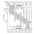
図1は、本発明の第1の実施形態に係る燃料電池10の要部分解斜視図であり、図2は、前記燃料電池10の概略縦断面説明図である。
【0024】
燃料電池10は、単位燃料電池セル12と、この単位燃料電池セル12を挟持する第1および第2セパレータ14、16とを備え、必要に応じてこれらが複数組だけ積層されている。単位燃料電池セル12は、固体高分子電解質膜18と、この電解質膜18を挟んで配設されるカソード側電極20およびアノード側電極22とを有するとともに、前記カソード側電極20および前記アノード側電極22には、例えば、多孔質層である多孔質カーボンペーパ等からなる第1および第2ガス拡散層24、26が配設される。
【0025】
単位燃料電池セル12の両側には、第1および第2ガスケット28、30が設けられ、前記第1ガスケット28は、カソード側電極20および第1ガス拡散層24を収納するための大きな開口部32を有する一方、前記第2ガスケット30は、アノード側電極22および第2ガス拡散層26を収納するための大きな開口部34を有する。単位燃料電池セル12と第1および第2ガスケット28、30とが、第1および第2セパレータ14、16によって挟持されるとともに、この第2セパレータ16には第3ガスケット35が配設される。
【0026】
第1セパレータ14は、その横方向両端上部側に連通孔として水素ガス等の燃料ガスを通過させるための燃料ガス入口36aと、酸素ガスまたは空気である酸化剤ガスを通過させるための酸化剤ガス入口38aとを設ける。
【0027】
第1セパレータ14の横方向両端中央側には、連通孔として純水やエチレングリコールやオイル等の冷却媒体を通過させるための冷却媒体入口40aと、使用後の前記冷却媒体を通過させるための冷却媒体出口40bとが設けられる。第1セパレータ14の横方向両端下部側には、燃料ガスを通過させるための燃料ガス出口36bと、酸化剤ガスを通過させるための酸化剤ガス出口38bとが、燃料ガス入口36aおよび酸化剤ガス入口38aと対角位置になるように設けられている。
【0028】
第1セパレータ14のカソード側電極20に対向する面14aには、酸化剤ガス入口38aに近接して複数本、例えば、6本のそれぞれ独立した第1酸化剤ガス流路溝(ガス流路)42が、水平方向に蛇行しながら重力方向に向かって設けられる。第1酸化剤ガス流路溝42は、3本の第2酸化剤ガス流路溝(ガス流路)44に合流し、この第2酸化剤ガス流路溝44が酸化剤ガス出口38bに近接して終端する。
【0029】
第1セパレータ14には、この第1セパレータ14を貫通するとともに、一端が面14aとは反対側の面14bで酸化剤ガス入口38aに連通する一方、他端が前記面14a側で第1酸化剤ガス流路溝42に連通する第1酸化剤ガス連結流路46と、一端が前記面14b側で酸化剤ガス出口38bに連通する一方、他端が前記面14a側で第2酸化剤ガス流路溝44に連通する第2酸化剤ガス連結流路48とが設けられる。
【0030】
図2および図3に示すように、第1酸化剤ガス連結流路46は、面14b側に設けられ、第1酸化剤ガス流路溝42に対応して所定間隔ずつ離間する6本の流路溝50を備え、この流路溝50の一端側が酸化剤ガス入口38aに連通する。流路溝50は、面14b側に所定の深さまで形成されており、その他端部側がそれぞれ貫通孔52に連通するとともに、前記貫通孔52が第1セパレータ14を貫通して面14a側で第1酸化剤ガス流路溝42に連通する。貫通孔52を構成する壁部には、酸化剤ガス流路溝42に連通する部分に対応してR部53が設けられている。なお、R部53に代替して面取り部を設けるようにしてもよい。
【0031】
第2酸化剤ガス連結流路48は、同様に、面14b側に設けられ、一端側が酸化剤ガス出口38bに連通して第2酸化剤ガス流路溝44に対応する3本の流路溝54と、前記流路溝54の他端側に連通するとともに、第1セパレータ14を貫通して面14a側で第2酸化剤ガス流路溝44に連通する3つの貫通孔56とを備える。
【0032】
図1、図4および図5に示すように、第2セパレータ16の横方向両端上部側には、連通孔として燃料ガス入口60aと酸化剤ガス入口62aとが設けられ、その横方向両端中央側には、連通孔として冷却媒体入口64aと冷却媒体出口64bとが設けられる。第2セパレータ16の横方向両端下部側には、連通孔として燃料ガス出口60bおよび酸化剤ガス出口62bが、燃料ガス入口60aおよび酸化剤ガス入口62aと対角位置になるように形成されている。
【0033】
図4に示すように、第2セパレータ16の面16aには、燃料ガス入口60aに近接して複数本、例えば、6本の第1燃料ガス流路溝(ガス流路)66が形成される。この第1燃料ガス流路溝66は、水平方向に蛇行しながら重力方向に向かって延在し、3本の第2燃料ガス流路溝(ガス流路)68に合流してこの第2燃料ガス流路溝68が燃料ガス出口60bの近傍で終端する。
【0034】
第2セパレータ16には、燃料ガス入口60aを面16b側から第1燃料ガス流路溝66に連通する第1燃料ガス連結流路70と、燃料ガス出口60bを前記面16b側から第2燃料ガス流路溝68に連通する第2燃料ガス連結流路72とが設けられる。図2、図4および図5に示すように、第1燃料ガス連結流路70は面16b側に設けられ、一端を燃料ガス入口60aに連通するとともに、第1燃料ガス流路溝66に対応して6本に設定される流路溝74と、前記流路溝74の他端に連通し、第2セパレータ16を貫通して第1燃料ガス流路溝66に連通する貫通孔76とを備える。
【0035】
第2燃料ガス連結流路72は、第1燃料ガス連結流路70と同様に、面16b側に設けられて燃料ガス出口60bに連通する3本の流路溝78と、第2セパレータ16を貫通して前記流路溝78をそれぞれ第2燃料ガス流路溝68に連通する貫通孔80とを備える。
【0036】
図2および図5に示すように、第2セパレータ16の面16bには、第3ガスケット35の開口部82に対応する段差部84が形成され、段差部84内には、冷却媒体入口64aおよび冷却媒体出口64bに近接して冷却媒体流路を構成する複数本の主流路溝86a、86bが形成される。主流路溝86a、86b間には、それぞれ複数本に分岐する分岐流路溝88が水平方向に延在して設けられている。
【0037】
第2セパレータ16には、冷却媒体入口64aと主流路溝86aとを連通する第1冷却媒体連結流路90と、冷却媒体出口64bと主流路溝86bとを連通する第2冷却媒体連結流路92とが設けられる。第1および第2冷却媒体連結流路90、92は、図4および図5に示すように、面16a側に設けられて冷却媒体入口64aおよび冷却媒体出口64bに連通する複数本の流路溝94a、94bと、第2セパレータ16を貫通して前記流路溝94a、94bを主流路溝86a、86bに連通する貫通孔96a、96bとを備える。
【0038】
図6に示すように、第1ガスケット28の横方向両端部には、燃料ガス入口100a、酸化剤ガス入口102a、冷却媒体入口104a、冷却媒体出口104b、燃料ガス出口100bおよび酸化剤ガス出口102bが設けられる。第1ガスケット28には、第1セパレータ14の面14aにおいて、酸化剤ガス入口38aと貫通孔52との間および酸化剤ガス出口38bと貫通孔56との間に対応して配置される幅狭部106a、106bが設けられている。
【0039】
図1および図7に示すように、第2ガスケット30は、横方向両端部に燃料ガス入口110a、酸化剤ガス入口112a、冷却媒体入口114a、冷却媒体出口114b、燃料ガス出口110bおよび酸化剤ガス出口112bを設けている。冷却媒体入口114aおよび冷却媒体出口114bは、第1および第2冷却媒体連結流路90、92を収容し得る大きさに設定されるとともに、第2ガスケット30には、第1および第2燃料ガス連結流路70、72を構成する貫通孔76、80と燃料ガス入口60a、燃料ガス出口60bとの間に対応して幅狭部116a、116bが形成される。
【0040】
図1に示すように、第3ガスケット35の横方向両端部には、燃料ガス入口120a、酸化剤ガス入口122a、冷却媒体入口124a、冷却媒体出口124b、燃料ガス出口120bおよび酸化剤ガス出口122bが設けられる。この第3ガスケット35には、第2セパレータ16の面16aに設けられている段差部84と冷却媒体入口64aおよび冷却媒体出口64bとの間に対応して幅狭部126a、126bが形成される。燃料ガス入口120aおよび燃料ガス出口120bは、第2セパレータ16に設けられている第1および第2燃料ガス連結流路70、72を収容するために、幅寸法が大きく設定されている。
【0041】
このように構成される第1の実施形態に係る燃料電池10の動作について、以下に説明する。
【0042】
燃料電池10内には、燃料ガス、例えば、炭化水素を改質した水素を含むガスが供給されるとともに、酸化剤ガスとして空気または酸素含有ガス(以下、単に空気ともいう)が供給され、さらに単位燃料電池セル12の発電面を冷却するために、冷却媒体が供給される。燃料電池10内に供給された燃料ガスは、図2および図5に示すように、第1燃料ガス連結流路70を構成する流路溝74に導入され、この流路溝74に連通する貫通孔76を介して面16b側から面16a側に移動し、この面16a側に形成されている第1燃料ガス流路溝66に供給される。
【0043】
図4に示すように、第1燃料ガス流路溝66に供給された燃料ガスは、第2セパレータ16の面16aに沿って水平方向に蛇行しながら重力方向に移動する。その際、燃料ガス中の水素ガスは、第2ガス拡散層26を通って単位燃料電池セル12のアノード側電極22に供給される(図2参照)。そして、未使用の燃料ガスは、第1燃料ガス流路溝66に沿って移動しながらアノード側電極22に供給される一方、未使用の燃料ガスが第2燃料ガス流路溝68を介して第2燃料ガス連結流路72を構成する貫通孔80に導入され、面16b側に移動した後に流路溝78から燃料ガス出口60bに排出される。
【0044】
また、燃料電池10内に供給された空気は、図2に示すように、第1セパレータ14の酸化剤ガス入口38aに導入され、この酸化剤ガス入口38aに連通する第1酸化剤ガス連結流路46を介して第1酸化剤ガス流路溝42に導入される。具体的には、図3に示すように、第1セパレータ14の面14b側に形成されている流路溝50に空気が導入されると、この空気は、前記流路溝50に連通する貫通孔52を介して前記第1セパレータ14を貫通し、面14a側に形成されている第1酸化剤ガス流路溝42に導入される。
【0045】
図6に示すように、第1酸化剤ガス流路溝42に供給された空気は、水平方向に蛇行しながら重力方向に移動する間、この空気中の酸素ガスが第1ガス拡散層24からカソード側電極20に供給される(図2参照)。一方、未使用の空気は、第2酸化剤ガス流路溝44を介して第2酸化剤ガス連結流路48から酸化剤ガス出口38bに排出される。これにより、単位燃料電池セル12で発電が行われ、例えば、図示しないモータに電力が供給されることになる。
【0046】
さらにまた、燃料電池10内に供給された冷却媒体は、第2セパレータ16の冷却媒体入口64aに導入された後、図4および図5に示すように、第1冷却媒体連結流路90を構成する流路溝94aから貫通孔96aを介して面16b側の主流路溝86aに供給される。冷却媒体は、主流路溝86aから分岐する複数本の分岐流路溝88を通って単位燃料電池セル12の発電面を冷却した後、主流路溝86bに合流する。そして、使用後の冷却媒体は、第2冷却媒体連結流路92を構成する貫通孔96bを通って面16a側の流路溝94bに導入され、冷却媒体出口64bから排出される。
【0047】
この場合、第1の実施形態では、図4に示すように、第2セパレータ16の面16aには、燃料ガス入口60aと燃料ガス出口60bに近接する位置で終端する第1および第2燃料ガス流路溝66、68が形成され、前記第1および第2燃料ガス流路溝66、68が貫通孔76、80を介して面16b側に設けられた流路溝74、78に連通し、この流路溝74、78から燃料ガス入口60aおよび燃料ガス出口60bに連通している。
【0048】
このため、第2セパレータ16の面16a側に燃料ガス入口60aと第1燃料ガス流路溝66とを連通する溝部を設ける際のように、この溝部の上部側に前記面16aと面一となる薄板状のカバーを設ける必要がなく、前記面16aに第2ガスケット30を直接重ね合わせることができる(図7参照)。
【0049】
これにより、カバーを用いる際のような接着工程が不要になるとともに、このカバーの欠落による燃料ガスの漏れ、あるいは前記カバーと第2セパレータ16の厚さの相違による締め付け不良等が発生することがない。従って、簡単な構成で、良好なシール性を確保するとともに、組み付け工程の簡素化を図り、かつ燃料電池10全体の簡素化および薄肉化が容易に遂行されるという効果が得られる。
【0050】
さらに、第1の実施形態では、連通孔である燃料ガス入口60aと燃料ガス出口60bとが、第2セパレータ16の面16aの外周縁部に設けられるとともに、前記燃料ガス入口60aおよび前記燃料ガス出口60bを第1および第2燃料ガス流路溝66、68に連通する第1および第2燃料ガス連結流路70、72が、前記燃料ガス入口60aおよび前記燃料ガス出口60bに近接して設けられている。このため、第1および第2燃料ガス連結流路70、72を構成する貫通孔76、80と、燃料ガス入口60aおよび燃料ガス出口60bとを連通する流路溝74、78の長さが可及的に短尺化され、圧損を大幅に低減し得るという利点がある。
【0051】
さらにまた、貫通孔76、80および流路溝74、78が複数本に設定されるとともに、面16aには複数本の第1および第2燃料ガス流路溝66、68が設けられている。これにより、面16aに沿って大量の燃料ガスを円滑に流すことができ、高電流密度の運転が容易に遂行可能になる。
【0052】
一方、第2セパレータ16の冷却媒体入口64aおよび冷却媒体出口64bに第1および第2冷却媒体連結流路90、92が設けられ、第1セパレータ14には、酸化剤ガス入口38aおよび酸化剤ガス出口38bに第1および第2酸化剤ガス連結流路46、48が設けられている。このため、薄板状のカバーが不要になるとともに、部品点数が一挙に削減され、燃料電池10全体の薄肉化を図ることができる。
【0053】
しかも、冷却媒体入口64aおよび冷却媒体出口64bが、第2セパレータ16の外周縁部に設けられており、図5に示すように、前記第2セパレータ16の面16bには、この面16b全面に沿って主流路溝68a、68bおよび分岐流路溝88が形成されている。従って、面16bの面内全体を確実に冷却することが可能になり、冷却効率が有効に向上するという利点が得られる。さらに、冷却媒体として、純水やエチレングリコールやオイル等を用いることにより、冷却能力が空冷に比べて相当に高くなり、特に、高電流密度の運転が容易に遂行可能になる。
【0054】
図8は、本発明の第2の実施形態に係る燃料電池140の一部縦断面説明図である。なお、第1の実施形態に係る燃料電池10と同一の構成要素には同一の参照符号を付して、その詳細な説明は省略する。
【0055】
燃料電池140では、第2セパレータ16に燃料ガス入口60aと第1燃料ガス流路溝66とを連通する第1燃料ガス連結流路142が設けられる。この第1燃料ガス連結流路142は、第2セパレータ16の面16b側に形成される流路溝144と、前記流路溝144を面16a側の第1燃料ガス流路溝66に連通する傾斜貫通孔146とを備える。傾斜貫通孔146は、第2セパレータ16の厚さ方向から内方に向かって傾斜して設けられている。
【0056】
このように構成される第2の実施形態では、燃料ガス入口60aに供給された燃料ガスが第1燃料ガス連結流路142を構成する流路溝144から傾斜貫通孔146を介して第1燃料ガス流路溝66に供給される。その際、燃料ガスは、傾斜貫通孔146の傾斜に沿って流路溝144から第1燃料ガス流路溝66に向かって一層円滑かつ確実に導入され、圧損を有効に低減し得るという利点がある。
【0057】
図9は、本発明の第3の実施形態に係る燃料電池を構成する第2セパレータ160の正面説明図である。なお、第1の実施形態に係る燃料電池10を構成する第2セパレータ16と同一の構成要素には同一の参照符号を付して、その詳細な説明は省略する。
【0058】
第2セパレータ160には、面160a側に形成される第1および第2燃料ガス流路溝66、68と燃料ガス入口60aおよび燃料ガス出口60bとを、面160b側から連通する第1および第2燃料ガス連結流路162、164と、前記面160b側に設けられる図示しない冷却媒体流路溝と冷却媒体入口64aおよび冷却媒体出口64bとを連通する第1および第2冷却媒体連結流路166、168とが設けられる。
【0059】
第1および第2燃料ガス連結流路162、164は、面160b側に設けられる流路溝74、78に一体的に連通して第2セパレータ160を貫通する長孔170、172を備える。第1および第2冷却媒体連結流路166、168は、同様に、流路溝94a、94bに一体的に連通するとともに、前記第2セパレータ160を貫通して設けられる長孔174、176を備える。
【0060】
このように構成される第3の実施形態では、例えば、燃料ガス入口60aに供給される燃料ガスが流路溝74に導入されると、長孔170に一体的に導入されて面160b側から面160a側に移動し、第1燃料ガス流路溝66に導入される。これにより、第2セパレータ160の面160a、160bには、溝部を閉塞するための薄板状のカバー等を用いる必要がなく、部品点数が一挙に削減されるとともに、簡単な構成で薄肉化が図られる等、第1および第2の実施形態と同様の効果が得られる。
【0061】
さらに、第3の実施形態では、第1および第2燃料ガス連結流路162、164が、流路溝74、78に一体的に連通して第2セパレータ160を貫通する長孔170、172を備えており、燃料ガスがこの長孔170、172を通過する際の圧損を有効に低減することができるという利点がある。同様に、第2セパレータ160には、冷却媒体を通過させるための長孔174、176が設けられており、圧損の低減が容易に図られる。
【0062】
しかも、第2セパレータ160を貫通して長孔170、172、174および176を形成すればよい。このため、第2セパレータ160の製造作業が一層簡素化し、該第2セパレータ160を経済的に製造することが可能になるという効果が得られる。
【0063】
【発明の効果】
本発明に係る燃料電池では、セパレータの外周縁部に貫通して設けられる連通孔と、このセパレータの電極発電面内に設けられるガス流路とを、前記電極発電面とは反対側の面側で前記連通孔と連通する連結流路を介して連通させることにより、前記電極発電面側に薄板状カバー等を嵌め込む必要がなく、構成および組み付け工程が一挙に簡素化し、高品質なかつ薄肉状の燃料電池を経済的に製造することが可能になる。
【図面の簡単な説明】
【図1】本発明の第1の実施形態に係る燃料電池の要部分解斜視図である。
【図2】前記燃料電池の概略縦断面説明図である。
【図3】前記燃料電池を構成する第1セパレータの正面説明図である。
【図4】前記燃料電池を構成する第2セパレータの一方の面の正面説明図である。
【図5】前記第2セパレータの他方の面の正面説明図である。
【図6】前記第1セパレータと第1ガスケットの斜視説明図である。
【図7】前記第2セパレータに第2ガスケットが配置された状態の正面説明図である。
【図8】本発明の第2の実施形態に係る燃料電池の一部縦断面説明図である。
【図9】本発明の第3の実施形態に係る燃料電池を構成する第2セパレータの面の正面説明図である。
【図10】従来技術に係る燃料電池の一部縦断面説明図である。
【図11】別の従来技術に係る燃料電池の一部正面説明図である。
【図12】図11中、XII−XII線断面図である。
【図13】さらに別の従来技術に係る燃料電池を構成するセパレータの分解斜視図である。
【図14】図13に示す前記セパレータの一方の面の正面図である。
【符号の説明】
10、140…燃料電池 12…単位燃料電池セル
14、16、160…セパレータ 18…電解質膜
20…カソード側電極 22…アノード側電極
24、26…ガス拡散層 28、30、35…ガスケット
36a、60a…燃料ガス入口 36b、60b…燃料ガス出口
38a、62a…酸化剤ガス入口 38b、62b…酸化剤ガス出口
40a、64a…冷却媒体入口 40b、64b…冷却媒体出口
42、44…酸化剤ガス流路溝 46、48…酸化剤ガス連結流路
50、94a、94b…流路溝
52、56、76、80、96a、96b…貫通孔
54、74、78、144…流路溝 66、68…燃料ガス流路溝
70、72、142、162、164…燃料ガス連結流路
86a、86b…主流路溝 88…分岐流路溝
90、92、166、168…冷却媒体連結流路
146…傾斜貫通孔
170、172、174、176…長孔[0001]
BACKGROUND OF THE INVENTION
The present invention relates to a fuel cell including a unit fuel cell configured by sandwiching an electrolyte between an anode side electrode and a cathode side electrode, and a separator sandwiching the unit fuel cell.
[0002]
[Prior art]
For example, a solid polymer type fuel cell has a unit fuel cell formed by arranging an anode side electrode and a cathode side electrode on both sides of an electrolyte composed of a polymer ion exchange membrane (cation exchange membrane), and a separator. In general, a predetermined number of unit fuel cells are stacked and used as a fuel cell stack.
[0003]
In this type of fuel cell, a fuel gas, such as a hydrogen-containing gas, supplied to the anode side electrode is hydrogen ionized on the catalyst electrode and moves to the cathode side electrode side through an appropriately humidified electrolyte. Electrons generated in the meantime are taken out to an external circuit and used as direct current electric energy. Since an oxidant gas, for example, an oxygen-containing gas or air is supplied to the cathode side electrode, the hydrogen ions, the electrons and oxygen react with each other to generate water at the cathode side electrode.
[0004]
In the fuel cell described above, an internal manifold is configured to supply fuel gas and oxidant gas (reactive gas) to the anode side electrode and the cathode side electrode of each unit fuel cell stacked. It has been broken. Specifically, the internal manifold includes a plurality of communication holes provided integrally connected to the stacked unit fuel cells and separators, and the reaction gas is supplied to the supply communication holes. Then, the reaction gas is supplied in a distributed manner for each unit fuel cell, while the used reaction gas is integrally discharged into the discharge communication hole. Further, in the fuel cell, a cooling medium is supplied to cool the electrode power generation surface, and the internal manifold may be provided with a communication hole for the cooling medium, similarly to the reaction gas. .
[0005]
As this type of technology, for example, in Japanese Patent Laid-Open No. 3-257760, as shown in FIG. 10, a
[0006]
However, in the above prior art, the
[0007]
Therefore, as shown in FIG. 11, the
[0008]
However, as described above, a process of fitting the
[0009]
Even when the cooling medium communication hole is provided in the internal manifold of the separator, it is necessary to use a thin plate cover, which causes the same problem as the above-described reaction gas.
[0010]
In order to solve the above problems, for example, a fuel cell stack disclosed in US Pat. No. 6,066,409 is known. In this fuel cell stack, as shown in FIG. 13, a
[0011]
As shown in FIG. 14, the non-power generation surface (non-reaction surface) 4c1 of the
[0012]
Through holes 5h1, 5h2 communicate with the outer ends of the channel grooves 5f1, 5f2, and the through holes 5h1, 5h2 communicate with the reaction gas channel 5i on the power generation surface 4c2 side of the separator 4b1 (FIG. 13 (see separator 4b2). This reactive gas flow path 5i is provided along the surface of the power generation surface 4c2. Between the separators 4b1 and 4b2, a gasket 8b is interposed to prevent mixing of different reaction gases in the internal manifold.
[0013]
In such a configuration, when one reaction gas is supplied to the supply port 5d1 constituting the internal manifold, the reaction gas moves to the outer peripheral side of the
[0014]
[Problems to be solved by the invention]
However, in the above prior art, the internal manifold is provided in the central portion of the
[0015]
Further, since the
[0016]
Furthermore, the cooling air
[0017]
The present invention solves this type of problem, and has a simple structure, ensures sealing performance, reduces the number of parts, achieves thinning, and ensures desired power generation performance. An object is to provide a battery.
[0018]
[Means for Solving the Problems]
Main departure Clearly In such a fuel cell, a communication hole for flowing a fuel gas or an oxidant gas is formed through the outer peripheral edge of the separator, and a gas flow for flowing the fuel gas or the oxidant gas into the electrode power generation surface of the separator. A road is provided. A connection channel is provided through the separator, and one end of the connection channel communicates with the communication hole on the surface opposite to the electrode power generation surface, while the other end is a gas channel on the electrode power generation surface side. Communicating with
[0019]
For this reason, for example, a thin plate is fitted to the introduction portion so as to ensure the sealing performance of the introduction portion as in the case where the communication hole and the gas flow path are communicated by an introduction portion such as a groove portion formed on the electrode power generation surface side. There is no need to This eliminates the need for a thin plate attachment process and prevents the occurrence of leakage due to the lack of the thin plate and the occurrence of poor tightening of the separator due to the level difference of the thin plate. In addition, since the communication hole is provided in the outer peripheral edge portion of the separator, the length of the connection channel from the communication hole to the gas channel can be significantly shortened, and the pressure loss can be effectively reduced.
[0020]
Furthermore, the number of parts can be reduced at a time as compared with a structure in which spacers, seal plates, gaskets, and the like are interposed between separators, and the dimensions in the stacking direction are greatly shortened. For this reason, it is possible to ensure a good sealing property with a simple process and configuration and to economically manufacture a thin-walled fuel cell.
[0021]
In addition, this departure Clearly In such a fuel cell, a communication hole through which a cooling medium flows is formed through the outer peripheral edge of the separator, and in the surface opposite to the electrode power generation surface of the separator, the cooling is performed in order to cool the electrode power generation surface. A cooling medium flow path for flowing the medium is provided. A connection channel is provided through the separator, and one end of the connection channel communicates with the communication hole on the electrode power generation surface side, while the other end of the connection channel flows on the surface side opposite to the electrode power generation surface. It communicates with the road.
[0022]
This eliminates the need for a thin plate attachment process, and prevents the occurrence of leakage due to the lack of the thin plate and the occurrence of poor tightening of the separator due to the level difference of the thin plate, and the configuration is effectively simplified. The Moreover, the communication hole is provided in the outer peripheral edge portion of the separator, and a cooling medium flow path for allowing the cooling medium to flow over the entire surface of the separator in order to cool the electrode power generation surface can be provided in the surface of the separator. . Therefore, the cooling efficiency of the electrode power generation surface is effectively improved, and in particular, operation at a high current density is possible.
[0023]
DETAILED DESCRIPTION OF THE INVENTION
FIG. 1 is an exploded perspective view of a main part of a
[0024]
The
[0025]
First and
[0026]
The
[0027]
A cooling
[0028]
On the
[0029]
The
[0030]
As shown in FIGS. 2 and 3, the first oxidant
[0031]
Similarly, the second oxidant
[0032]
As shown in FIGS. 1, 4, and 5, a
[0033]
As shown in FIG. 4, a plurality of, for example, six first fuel gas flow channel grooves (gas flow channels) 66 are formed on the
[0034]
The
[0035]
Similarly to the first fuel gas
[0036]
As shown in FIGS. 2 and 5, a stepped
[0037]
The
[0038]
As shown in FIG. 6, at the lateral ends of the
[0039]
As shown in FIGS. 1 and 7, the
[0040]
As shown in FIG. 1, the
[0041]
The operation of the
[0042]
A fuel gas, for example, a gas containing hydrogen obtained by reforming hydrocarbons is supplied into the
[0043]
As shown in FIG. 4, the fuel gas supplied to the first fuel
[0044]
Further, as shown in FIG. 2, the air supplied into the
[0045]
As shown in FIG. 6, while the air supplied to the first oxidant
[0046]
Furthermore, after the cooling medium supplied into the
[0047]
In this case, in the first embodiment, as shown in FIG. 4, on the
[0048]
For this reason, as in the case of providing a groove portion communicating with the
[0049]
This eliminates the need for an adhesion process as in the case of using the cover, and causes a leakage of fuel gas due to the lack of the cover, or a tightening failure due to a difference in thickness between the cover and the
[0050]
Further, in the first embodiment, the
[0051]
Furthermore, a plurality of through
[0052]
On the other hand, first and second cooling
[0053]
Moreover, the cooling
[0054]
FIG. 8 is a partial vertical cross-sectional explanatory view of a
[0055]
In the
[0056]
In the second embodiment configured as described above, the fuel gas supplied to the
[0057]
FIG. 9 is an explanatory front view of the
[0058]
In the
[0059]
The first and second fuel
[0060]
In the third embodiment configured as described above, for example, when the fuel gas supplied to the
[0061]
Furthermore, in the third embodiment, the first and second fuel gas
[0062]
Moreover, the
[0063]
【The invention's effect】
In the fuel cell according to the present invention, the communication hole provided through the outer peripheral edge of the separator and the gas flow path provided in the electrode power generation surface of the separator are on the surface side opposite to the electrode power generation surface. In this way, it is not necessary to fit a thin plate-like cover or the like on the electrode power generation surface side, and the configuration and assembly process are simplified at a stroke, and the high quality and thin wall shape. It becomes possible to manufacture the fuel cell economically.
[Brief description of the drawings]
FIG. 1 is an exploded perspective view of a main part of a fuel cell according to a first embodiment of the present invention.
FIG. 2 is a schematic longitudinal sectional view of the fuel cell.
FIG. 3 is a front explanatory view of a first separator constituting the fuel cell.
FIG. 4 is a front explanatory view of one surface of a second separator constituting the fuel cell.
FIG. 5 is a front explanatory view of the other surface of the second separator.
FIG. 6 is a perspective explanatory view of the first separator and the first gasket.
FIG. 7 is a front explanatory view showing a state in which a second gasket is arranged on the second separator.
FIG. 8 is a partial vertical cross-sectional explanatory view of a fuel cell according to a second embodiment of the present invention.
FIG. 9 is an explanatory front view of a surface of a second separator constituting a fuel cell according to a third embodiment of the present invention.
FIG. 10 is a partial vertical cross-sectional explanatory view of a conventional fuel cell.
FIG. 11 is a partial front view of a fuel cell according to another prior art.
12 is a cross-sectional view taken along line XII-XII in FIG.
FIG. 13 is an exploded perspective view of a separator constituting a fuel cell according to another prior art.
14 is a front view of one surface of the separator shown in FIG. 13;
[Explanation of symbols]
DESCRIPTION OF
14, 16, 160 ...
20 ... Cathode side electrode 22 ... Anode side electrode
24, 26 ...
36a, 60a ...
38a, 62a ...
40a, 64a ... Cooling
42, 44 ... oxidizing
50, 94a, 94b ... flow channel
52, 56, 76, 80, 96a, 96b ... through hole
54, 74, 78, 144: flow
70, 72, 142, 162, 164 ... fuel gas connection flow path
86a, 86b ...
90, 92, 166, 168 ... Cooling medium connection channel
146 ... inclined through hole
170,172,174,176 ... long hole
Claims (12)
前記セパレータの外周縁部に貫通して設けられ、燃料ガスまたは酸化剤ガスを流すための連通孔と、
前記セパレータの電極発電面内に設けられ、前記アノード側電極または前記カソード側電極に前記燃料ガスまたは前記酸化剤ガスを供給するための複数本のガス流路溝を備えるガス流路と、
前記セパレータを貫通して設けられるとともに、一端が前記電極発電面とは反対の面側で前記連通孔に連通しかつ他端が該電極発電面側で前記ガス流路に連通する連結流路と、
を備え、
前記連結流路は、前記セパレータの前記ガス流路が設けられる面とは反対の面に設けられ、一端部が前記連通孔に直接連通し、前記ガス流路溝に対応する本数に設定された流路溝と、
前記セパレータを貫通し、前記反対の面で前記流路溝の他端部に直接連通しかつ前記流路溝と前記ガス流路とを連通する貫通孔と、
を備えることを特徴とする燃料電池。A fuel cell comprising a solid polymer unit fuel cell configured by sandwiching a solid polymer electrolyte membrane between an anode side electrode and a cathode side electrode, and a separator sandwiching the solid polymer type unit fuel cell. And
A through hole provided through the outer peripheral edge of the separator, for flowing a fuel gas or an oxidant gas;
A gas flow path provided in the electrode power generation surface of the separator, and comprising a plurality of gas flow path grooves for supplying the fuel gas or the oxidant gas to the anode side electrode or the cathode side electrode;
A connecting channel provided through the separator and having one end communicating with the communication hole on the side opposite to the electrode power generation surface and the other end communicating with the gas channel on the electrode power generation surface side; ,
With
The connecting passage, the said surface gas flow passage is provided of the separator is provided on the opposite side, one end is communicated directly to the communication hole, it is set to the number corresponding to the gas flow field groove A channel groove;
A through hole that penetrates the separator, communicates directly with the other end of the flow channel on the opposite surface, and communicates the flow channel and the gas flow channel;
A fuel cell comprising:
前記セパレータの外周縁部に貫通して設けられ、冷却媒体を流すための連通孔と、
前記セパレータの電極発電面とは反対の面内に設けられ、前記電極発電面を冷却する前記冷却媒体を供給するための複数本の冷却媒体流路溝を備える冷却媒体流路と、
前記セパレータを貫通して設けられるとともに、一端が前記電極発電面側で前記連通孔に連通しかつ他端が該電極発電面とは反対の面側で前記冷却媒体流路に連通する連結流路と、
を備え、
前記連結流路は、前記セパレータの前記電極発電面側の面に設けられ、一端部が前記連通孔に直接連通し、前記冷却媒体流路溝に対応する本数に設定された流路溝と、
前記セパレータを貫通し、前記電極発電面側の面で前記流路溝の他端部に直接連通しかつ前記流路溝と前記冷却媒体流路とを連通する貫通孔と、
を備えることを特徴とする燃料電池。A fuel cell comprising a solid polymer unit fuel cell configured by sandwiching a solid polymer electrolyte membrane between an anode side electrode and a cathode side electrode, and a separator sandwiching the solid polymer type unit fuel cell. And
A through hole provided through the outer peripheral edge of the separator, and for flowing a cooling medium;
A cooling medium flow path provided in a surface opposite to the electrode power generation surface of the separator and provided with a plurality of cooling medium flow channel grooves for supplying the cooling medium for cooling the electrode power generation surface;
A connecting flow path provided through the separator and having one end communicating with the communication hole on the electrode power generation surface side and the other end communicating with the cooling medium flow path on the surface opposite to the electrode power generation surface When,
With
The connection channel is provided on a surface of the electrode power side of the separator, one end communicated directly to the communication hole, a flow channel that is set to the number corresponding to the cooling medium flow passage grooves,
A through hole that penetrates the separator, communicates directly with the other end of the flow channel on the electrode power generation surface side, and communicates the flow channel with the cooling medium flow channel;
A fuel cell comprising:
一方の前記セパレータの外周縁部に貫通して設けられ、燃料ガスまたは酸化剤ガスの一方を流すためのガス連通孔と、
一方の前記セパレータの外周縁部に貫通して設けられ、冷却媒体を流すための冷却媒体連通孔と、
一方の前記セパレータの電極発電面内に設けられ、前記アノード側電極または前記カソード側電極に前記燃料ガスまたは前記酸化剤ガスの一方を供給するための複数本のガス流路溝を備えるガス流路と、
一方の前記セパレータの電極発電面とは反対の面内に設けられ、前記電極発電面を冷却する前記冷却媒体を供給するための複数本の冷却媒体流路溝を備える冷却媒体流路と、
一方の前記セパレータを貫通して設けられるとともに、一端が前記冷却媒体流路の面側で前記連通孔に連通しかつ他端が前記ガス流路の面側で該ガス流路に連通するガス連結流路と、
一方の前記セパレータを貫通して設けられるとともに、一端が前記ガス流路の面側で前記冷却媒体連通孔に連通しかつ他端が前記冷却媒体流路の面側で該冷却媒体流路に連通する冷却媒体連結流路と、
を備え、
前記ガス連結流路は、前記セパレータの前記冷却媒体流路側の面に設けられ、一端部が前記ガス連通孔に直接連通し、前記ガス流路溝に対応する本数に設定されたガス用流路溝と、
前記セパレータを貫通し、前記冷却媒体流路側の面で前記ガス用流路溝の他端部に直接連通しかつ前記ガス用流路溝と前記ガス流路とを連通するガス用貫通孔と、
を設ける一方、
前記冷却媒体連結流路は、前記ガス流路側の面に設けられ、一端部が前記冷却媒体連通孔に直接連通し、前記冷却媒体流路溝に対応する本数に設定された冷却媒体用流路溝と、
前記セパレータを貫通し、前記ガス流路側の面で前記冷却媒体用流路溝の他端部に直接連通しかつ前記冷却媒体用流路溝と前記冷却媒体流路とを連通する冷却媒体用貫通孔と、
を設けることを特徴とする燃料電池。A fuel cell comprising a solid polymer unit fuel cell configured by sandwiching a solid polymer electrolyte membrane between an anode side electrode and a cathode side electrode, and a pair of separators sandwiching the solid polymer type unit fuel cell Because
A gas communication hole provided through the outer peripheral edge of one of the separators for flowing one of fuel gas or oxidant gas;
A cooling medium communication hole provided through the outer peripheral edge of one of the separators, and for flowing a cooling medium;
A gas flow path provided in the electrode power generation surface of one of the separators and having a plurality of gas flow path grooves for supplying one of the fuel gas or the oxidant gas to the anode side electrode or the cathode side electrode When,
A cooling medium flow path provided in a surface opposite to the electrode power generation surface of one of the separators and provided with a plurality of cooling medium flow channel grooves for supplying the cooling medium for cooling the electrode power generation surface;
A gas connection that is provided through one of the separators, and that has one end communicating with the communication hole on the surface side of the cooling medium flow path and the other end communicating with the gas flow path on the surface side of the gas flow path. A flow path;
One of the separators is provided so as to pass through, and one end communicates with the cooling medium communication hole on the surface side of the gas flow path and the other end communicates with the cooling medium flow path on the surface side of the cooling medium flow path. A cooling medium connection flow path,
With
The gas connection channel is provided on a surface of the cooling medium flow path side of the separator, one end communicated directly to the gas passage, the gas flow path which is set to the number corresponding to the gas flow field groove Groove,
A gas through hole that penetrates the separator, communicates directly with the other end of the gas flow channel on the surface of the cooling medium flow channel, and communicates the gas flow channel with the gas flow channel;
While providing
The coolant connection channel is provided on a surface of the gas passage side, one end is communicated directly to the cooling medium passage, said cooling medium channel coolant flow path is set to the number corresponding to the grooves Groove,
A cooling medium penetration that passes through the separator, communicates directly with the other end of the cooling medium flow channel on the gas flow channel side, and communicates the cooling medium flow channel with the cooling medium flow channel. Holes,
A fuel cell comprising:
他方の前記セパレータの電極発電面内に設けられ、前記アノード側電極または前記カソード側電極に前記燃料ガスまたは前記酸化剤ガスの他方を供給するためのガス流路と、
他方の前記セパレータを貫通して設けられるとともに、一端が前記電極発電面とは反対の面側で前記ガス連通孔に連通しかつ他端が該電極発電面側で前記ガス流路に連通するガス連結流路と、
を備えることを特徴とする燃料電池。The fuel cell according to claim 11, wherein the gas communication hole is provided penetrating the outer peripheral edge of the other separator and allows the other of the fuel gas or the oxidant gas to flow.
A gas flow path provided in the electrode power generation surface of the other separator, for supplying the other of the fuel gas or the oxidant gas to the anode side electrode or the cathode side electrode;
A gas that is provided through the other separator, has one end communicating with the gas communication hole on the side opposite to the electrode power generation surface and the other end communicating with the gas flow path on the electrode power generation surface side. A connecting channel;
A fuel cell comprising:
Priority Applications (6)
| Application Number | Priority Date | Filing Date | Title |
|---|---|---|---|
| JP2000234873A JP4809519B2 (en) | 1999-09-10 | 2000-08-02 | Fuel cell |
| US09/656,910 US6686085B1 (en) | 1999-09-10 | 2000-09-07 | Fuel cell |
| DE60038853T DE60038853D1 (en) | 1999-09-10 | 2000-09-08 | fuel cell |
| EP00119665A EP1083616B1 (en) | 1999-09-10 | 2000-09-08 | Fuel cell |
| CA002317884A CA2317884C (en) | 1999-09-10 | 2000-09-08 | Fuel cell |
| US10/679,119 US7226688B2 (en) | 1999-09-10 | 2003-10-03 | Fuel cell |
Applications Claiming Priority (4)
| Application Number | Priority Date | Filing Date | Title |
|---|---|---|---|
| JP1999257009 | 1999-09-10 | ||
| JP25700999 | 1999-09-10 | ||
| JP11-257009 | 1999-09-10 | ||
| JP2000234873A JP4809519B2 (en) | 1999-09-10 | 2000-08-02 | Fuel cell |
Publications (3)
| Publication Number | Publication Date |
|---|---|
| JP2001148252A JP2001148252A (en) | 2001-05-29 |
| JP2001148252A5 JP2001148252A5 (en) | 2007-08-30 |
| JP4809519B2 true JP4809519B2 (en) | 2011-11-09 |
Family
ID=26543014
Family Applications (1)
| Application Number | Title | Priority Date | Filing Date |
|---|---|---|---|
| JP2000234873A Expired - Lifetime JP4809519B2 (en) | 1999-09-10 | 2000-08-02 | Fuel cell |
Country Status (5)
| Country | Link |
|---|---|
| US (1) | US6686085B1 (en) |
| EP (1) | EP1083616B1 (en) |
| JP (1) | JP4809519B2 (en) |
| CA (1) | CA2317884C (en) |
| DE (1) | DE60038853D1 (en) |
Families Citing this family (44)
| Publication number | Priority date | Publication date | Assignee | Title |
|---|---|---|---|---|
| US7527889B2 (en) * | 1999-10-19 | 2009-05-05 | Honda Giken Kogyo Kabushiki Kaisha | Fuel cell stack |
| US6936369B1 (en) * | 1999-10-19 | 2005-08-30 | Honda Giken Kogyo Kabushiki Kaisha | Fuel cell stack |
| JP3596761B2 (en) | 2000-12-27 | 2004-12-02 | 松下電器産業株式会社 | Polymer electrolyte fuel cell |
| US6599653B1 (en) | 2001-05-15 | 2003-07-29 | Dana Corporation | Molded fuel cell plates with seals |
| JP4841769B2 (en) * | 2001-09-07 | 2011-12-21 | 本田技研工業株式会社 | Fuel cell |
| JP4812990B2 (en) * | 2001-09-19 | 2011-11-09 | 本田技研工業株式会社 | Fuel cell |
| JP3830805B2 (en) * | 2001-11-07 | 2006-10-11 | 本田技研工業株式会社 | Fuel cell |
| JP3693955B2 (en) | 2001-12-26 | 2005-09-14 | 本田技研工業株式会社 | Fuel cell |
| US8283085B2 (en) | 2001-12-26 | 2012-10-09 | Honda Motor Co., Ltd. | Fuel cell and separator thereof |
| JP3702848B2 (en) * | 2002-01-10 | 2005-10-05 | 日産自動車株式会社 | Fuel cell |
| ITMI20020869A1 (en) † | 2002-04-23 | 2003-10-23 | Nuvera Fuel Cells Europ Srl | ELECTROCHEMICAL GENERATOR AND REDUCED DIAPHRAGM MEMBRANE |
| US7087339B2 (en) | 2002-05-10 | 2006-08-08 | 3M Innovative Properties Company | Fuel cell membrane electrode assembly with sealing surfaces |
| US7217471B2 (en) | 2002-05-17 | 2007-05-15 | 3M Innovative Properties Company | Membrane electrode assembly with compression control gasket |
| JP4815733B2 (en) * | 2003-03-24 | 2011-11-16 | 日産自動車株式会社 | Fuel cell system |
| US7459227B2 (en) * | 2003-04-18 | 2008-12-02 | General Motors Corporation | Stamped fuel cell bipolar plate |
| JP4727910B2 (en) * | 2003-05-01 | 2011-07-20 | 本田技研工業株式会社 | Fuel cell |
| US7704625B2 (en) | 2003-05-01 | 2010-04-27 | Honda Motor Co., Ltd. | Fuel cell |
| EP1625633A1 (en) * | 2003-05-16 | 2006-02-15 | Hydrogenics Corporation | Symmetrical flow field plates |
| US7655339B1 (en) | 2003-06-06 | 2010-02-02 | Dana Automotive Systems Group, Llc | Molded fuel cell plates with seals |
| WO2004114448A2 (en) | 2003-06-25 | 2004-12-29 | Hydrogenics Corporation | Passive electrode blanketing in a fuel cell |
| WO2005020346A2 (en) * | 2003-06-27 | 2005-03-03 | Ultracell Corporation | Micro fuel cell architecture |
| US7353085B2 (en) | 2003-09-22 | 2008-04-01 | Hydrogenics Corporation | Electrolyzer cell stack system |
| US20050186458A1 (en) | 2003-09-22 | 2005-08-25 | Ali Rusta-Sallehy | Electrolyzer cell stack system |
| US7993798B2 (en) | 2003-12-02 | 2011-08-09 | Nissan Motor Co., Ltd | Manufacture of fuel cell |
| JP4494057B2 (en) * | 2004-03-26 | 2010-06-30 | 本田技研工業株式会社 | Fuel cell separator and fuel cell manufacturing method using the same |
| JP2005293878A (en) * | 2004-03-31 | 2005-10-20 | Honda Motor Co Ltd | Fuel cell stack |
| US7531264B2 (en) * | 2004-06-07 | 2009-05-12 | Hyteon Inc. | Fuel cell stack with even distributing gas manifolds |
| US7569303B2 (en) | 2004-09-24 | 2009-08-04 | Hydrogenics Corporation | Membrane electrode assembly with modified catalyst layout |
| JP4562501B2 (en) * | 2004-11-25 | 2010-10-13 | 本田技研工業株式会社 | Fuel cell |
| JP2006164606A (en) * | 2004-12-03 | 2006-06-22 | Mitsubishi Electric Corp | Separator for fuel cell, and fuel cell stack |
| JP4696545B2 (en) | 2004-12-08 | 2011-06-08 | トヨタ自動車株式会社 | Fuel cell |
| DE112006000193B4 (en) * | 2005-01-13 | 2020-08-27 | Toyota Jidosha Kabushiki Kaisha | Fuel cell, separator and gas separator for a fuel cell |
| JP4692001B2 (en) | 2005-02-08 | 2011-06-01 | トヨタ自動車株式会社 | Fuel cell separator |
| JP4673141B2 (en) * | 2005-06-22 | 2011-04-20 | 本田技研工業株式会社 | Fuel cell and fuel cell separator |
| US7727660B2 (en) | 2005-07-27 | 2010-06-01 | Ird Fuel Cells A/S | Modified fuel cells with internal humidification and/or temperature control systems |
| JP4611196B2 (en) * | 2005-12-28 | 2011-01-12 | 本田技研工業株式会社 | Fuel cell and fuel cell stack |
| US8221930B2 (en) * | 2006-08-23 | 2012-07-17 | Daimler Ag | Bipolar separators with improved fluid distribution |
| US20080050639A1 (en) * | 2006-08-23 | 2008-02-28 | Michael Medina | Bipolar flow field plate assembly and method of making the same |
| US20080076005A1 (en) * | 2006-09-22 | 2008-03-27 | Michel Bitton | Fuel cell fluid distribution system |
| JP5046615B2 (en) * | 2006-11-09 | 2012-10-10 | 本田技研工業株式会社 | Fuel cell |
| US20100035121A1 (en) * | 2007-04-20 | 2010-02-11 | Kazunori Shibata | Fuel cell separator and fuel cell |
| JP5603894B2 (en) * | 2012-03-19 | 2014-10-08 | 本田技研工業株式会社 | Fuel cell |
| FR2997560B1 (en) * | 2012-10-25 | 2015-04-24 | Air Liquide | FUEL CELL PLATE AND CELL STACK COMPRISING SUCH A PLATE |
| FR3102308B1 (en) * | 2019-10-18 | 2022-06-03 | Air Liquide | Fuel cell bipolar plate |
Family Cites Families (17)
| Publication number | Priority date | Publication date | Assignee | Title |
|---|---|---|---|---|
| JPS58138268A (en) * | 1982-02-12 | 1983-08-17 | Nissan Motor Co Ltd | Firing device of diesel engine |
| JPS60130567A (en) * | 1983-12-19 | 1985-07-12 | Teikoku Hormone Mfg Co Ltd | 3-substituted-2-phenylindole derivative |
| JPS6471071A (en) * | 1987-09-10 | 1989-03-16 | Ishikawajima Harima Heavy Ind | Separator for fuel cell |
| JPH01173576A (en) * | 1987-12-28 | 1989-07-10 | Hitachi Ltd | Fuel cell separator |
| US5108849A (en) * | 1989-08-30 | 1992-04-28 | Her Majesty The Queen In Right Of Canada, As Represented By The Minister Of National Defence In Her Britannic Majesty's Government Of The United Kingdom Of Great Britain And Northern Ireland | Fuel cell fluid flow field plate |
| JPH03257760A (en) | 1990-03-08 | 1991-11-18 | Nkk Corp | Solid electrolyte type fuel cell |
| US5230966A (en) * | 1991-09-26 | 1993-07-27 | Ballard Power Systems Inc. | Coolant flow field plate for electrochemical fuel cells |
| JPH05109415A (en) * | 1991-10-16 | 1993-04-30 | Mitsubishi Heavy Ind Ltd | Gas separator for fuel cell |
| JP3382708B2 (en) * | 1994-03-25 | 2003-03-04 | 三菱重工業株式会社 | Gas separator for solid polymer electrolyte fuel cells |
| US5514487A (en) * | 1994-12-27 | 1996-05-07 | Ballard Power Systems Inc. | Edge manifold assembly for an electrochemical fuel cell stack |
| ATE301335T1 (en) * | 1995-05-25 | 2005-08-15 | Honda Motor Co Ltd | FUEL CELL AND METHOD FOR CONTROL THEREOF |
| JP3491066B2 (en) * | 1995-08-15 | 2004-01-26 | ヤマハ発動機株式会社 | Fuel cell |
| JP3741805B2 (en) * | 1996-12-03 | 2006-02-01 | 本田技研工業株式会社 | Fuel cell |
| US6057054A (en) | 1997-07-16 | 2000-05-02 | Ballard Power Systems Inc. | Membrane electrode assembly for an electrochemical fuel cell and a method of making an improved membrane electrode assembly |
| JP4205774B2 (en) * | 1998-03-02 | 2009-01-07 | 本田技研工業株式会社 | Fuel cell |
| US6174616B1 (en) * | 1998-10-07 | 2001-01-16 | Plug Power Inc. | Fuel cell assembly unit for promoting fluid service and design flexibility |
| JP2000331691A (en) * | 1999-05-18 | 2000-11-30 | Honda Motor Co Ltd | Fuel cell stack |
-
2000
- 2000-08-02 JP JP2000234873A patent/JP4809519B2/en not_active Expired - Lifetime
- 2000-09-07 US US09/656,910 patent/US6686085B1/en not_active Expired - Lifetime
- 2000-09-08 DE DE60038853T patent/DE60038853D1/en not_active Expired - Lifetime
- 2000-09-08 CA CA002317884A patent/CA2317884C/en not_active Expired - Lifetime
- 2000-09-08 EP EP00119665A patent/EP1083616B1/en not_active Expired - Lifetime
Also Published As
| Publication number | Publication date |
|---|---|
| CA2317884C (en) | 2009-02-03 |
| EP1083616A2 (en) | 2001-03-14 |
| EP1083616A3 (en) | 2004-03-17 |
| US6686085B1 (en) | 2004-02-03 |
| EP1083616B1 (en) | 2008-05-14 |
| JP2001148252A (en) | 2001-05-29 |
| CA2317884A1 (en) | 2001-03-10 |
| DE60038853D1 (en) | 2008-06-26 |
Similar Documents
| Publication | Publication Date | Title |
|---|---|---|
| JP4809519B2 (en) | Fuel cell | |
| JP4344484B2 (en) | Solid polymer cell assembly | |
| US6764783B2 (en) | Electrochemical fuel cell stack with improved reactant manifolding and sealing | |
| JP4067371B2 (en) | Fuel cell | |
| JP3693955B2 (en) | Fuel cell | |
| JP4634933B2 (en) | Fuel cell | |
| US7226688B2 (en) | Fuel cell | |
| JP2008192368A (en) | Fuel cell stack | |
| JP4268536B2 (en) | Fuel cell | |
| JP2007005076A (en) | Fuel battery and separator for fuel battery | |
| JP4031936B2 (en) | Fuel cell | |
| JP3868810B2 (en) | Fuel cell | |
| JP4841769B2 (en) | Fuel cell | |
| JP4121315B2 (en) | Fuel cell | |
| JP4214027B2 (en) | Fuel cell | |
| JP4031952B2 (en) | Fuel cell | |
| JP4812990B2 (en) | Fuel cell | |
| JP4185734B2 (en) | Fuel cell stack | |
| JP4444862B2 (en) | Fuel cell or separator | |
| JP2000164227A (en) | Gas manifold integrated separator and fuel cell | |
| JP5081494B2 (en) | Fuel cell | |
| JP4981400B2 (en) | Fuel cell | |
| JP2004335179A (en) | Fuel cell | |
| JP4340413B2 (en) | Polymer electrolyte fuel cell | |
| JP2002100380A (en) | Fuel cell and fuel cell stack |
Legal Events
| Date | Code | Title | Description |
|---|---|---|---|
| A521 | Request for written amendment filed |
Free format text: JAPANESE INTERMEDIATE CODE: A523 Effective date: 20070712 |
|
| A621 | Written request for application examination |
Free format text: JAPANESE INTERMEDIATE CODE: A621 Effective date: 20070712 |
|
| A977 | Report on retrieval |
Free format text: JAPANESE INTERMEDIATE CODE: A971007 Effective date: 20100625 |
|
| A131 | Notification of reasons for refusal |
Free format text: JAPANESE INTERMEDIATE CODE: A131 Effective date: 20100629 |
|
| A521 | Request for written amendment filed |
Free format text: JAPANESE INTERMEDIATE CODE: A523 Effective date: 20100830 |
|
| A131 | Notification of reasons for refusal |
Free format text: JAPANESE INTERMEDIATE CODE: A131 Effective date: 20110531 |
|
| A521 | Request for written amendment filed |
Free format text: JAPANESE INTERMEDIATE CODE: A523 Effective date: 20110726 |
|
| TRDD | Decision of grant or rejection written | ||
| A01 | Written decision to grant a patent or to grant a registration (utility model) |
Free format text: JAPANESE INTERMEDIATE CODE: A01 Effective date: 20110816 |
|
| A01 | Written decision to grant a patent or to grant a registration (utility model) |
Free format text: JAPANESE INTERMEDIATE CODE: A01 |
|
| A61 | First payment of annual fees (during grant procedure) |
Free format text: JAPANESE INTERMEDIATE CODE: A61 Effective date: 20110819 |
|
| FPAY | Renewal fee payment (event date is renewal date of database) |
Free format text: PAYMENT UNTIL: 20140826 Year of fee payment: 3 |
|
| R150 | Certificate of patent or registration of utility model |
Free format text: JAPANESE INTERMEDIATE CODE: R150 Ref document number: 4809519 Country of ref document: JP Free format text: JAPANESE INTERMEDIATE CODE: R150 |
|
| R250 | Receipt of annual fees |
Free format text: JAPANESE INTERMEDIATE CODE: R250 |
|
| EXPY | Cancellation because of completion of term |