JP4034005B2 - Measuring device - Google Patents
Measuring device Download PDFInfo
- Publication number
- JP4034005B2 JP4034005B2 JP14344599A JP14344599A JP4034005B2 JP 4034005 B2 JP4034005 B2 JP 4034005B2 JP 14344599 A JP14344599 A JP 14344599A JP 14344599 A JP14344599 A JP 14344599A JP 4034005 B2 JP4034005 B2 JP 4034005B2
- Authority
- JP
- Japan
- Prior art keywords
- total station
- measurement
- collimation
- image
- turning
- Prior art date
- Legal status (The legal status is an assumption and is not a legal conclusion. Google has not performed a legal analysis and makes no representation as to the accuracy of the status listed.)
- Expired - Fee Related
Links
Images
Description
【0001】
【発明の属する技術分野】
本発明は、測地、地形計測、急崖計測、又は工事測量などの各種の三次元計測に適用される計測装置に関する。
【0002】
【従来の技術】
従来のこの種の計測装置としては、例えば測距機能及び測角機能を併せ持ち、斜距離、水平角、鉛直角の同時計測、並びに計測データの電子野帳への自動記録が可能であるトータルステーションと、測距のために測点に設置されるターゲットとで構成されるものが知られている。
【0003】
このタイプの計測装置によれば、ターゲットが設置された測点の三次元座標を瞬時に求めること、及び電子野帳に記録された計測データの利用によりコンピュータを用いて数量管理を行うことが可能になる他、手作業で記帳する場合に生じ易かったエラーやミスが少なくなり、計測結果の信頼性を高めることも可能になる。
【0004】
【発明が解決しようとする課題】
しかしながら、このタイプの計測装置では、危険な崖地や広域の土地造成工事に対する地形計測を行う場合、反射プリズムを持ち歩きながらの計測作業が必要となり、かかる計測作業にあっては人手と費用及び時間がかかる苦渋を伴うという問題があり、また、地山の崩壊の虞がある箇所での計測作業にあっては人命に危険が及ぶため有人での計測が難しいという問題がある。
【0005】
そこで、本発明の目的は、危険な崖地や広域の土地造成工事に対する地形計測作業において、反射プリズムを持ち歩く等の苦渋作業を回避でき、安全性、迅速性の確保ができる計測装置を提供することにある。
【0006】
前記目的を解決するために、本発明に係る測量装置は、計測対象に面して据付がされたノンプリズム型のトータルステーションと、前記トータルステーションの操作で視準方向の設定以外のものを行う操作手段と、前記トータルステーションの各部分であって、水平軸が支持される部分を鉛直軸周りで旋回させ、視準軸が支持される部分を水平軸周りで旋回させる旋回手段と、前記視準軸が支持される部分と一体に設けられ、光軸が前記視準軸と一定間隔で平行に設定される画像撮影手段と、前記画像撮影手段にて撮影された画像を前記操作を行う箇所においてリアルタイムで表示する画像表示手段と、前記画像上で入力手段を用いて特定された計測を行うべき位置の座標データに基づいて、該位置に対応する計測対象上の点を視準するように前記旋回手段を制御して前記トータルステーションの視準方向の設定をする視準方向設定手段と、前記トータルステーションが視準している計測対象上の点に対応する位置を、前記画像上に表示する視準位置表示手段と、を含むことを特徴とする。
【0007】
即ち、本発明は、計測対象に面して据付がされたトータルステーションのほか、遠隔操作手段、旋回手段、画像撮影手段、画像表示手段、視準位置表示手段、及び視準方向設定手段を備え、これによりトータルステーションの視準方向の設定を画像上で行う技術的手段を実現することにより、危険な崖地や広域の土地造成工事に対する地形計測作業において、反射プリズムを持ち歩く等の苦渋作業を回避でき、安全性、迅速性の確保ができる計測装置の提供を可能にする。
【0008】
このような技術的手段において、画像撮影手段の光軸方向は、画像表示手段にて表示された画像の中央において表示されることになり、即ち、トータルステーションが現に視準している計測対象上の点も該画像の略中央において表示されることとなる。しかし、画像撮影手段の光軸が視準軸と一定間隔で平行に設定されていることから、トータルステーションが視準している計測対象上の点と画像の中央との間でズレを生じ、また、このズレは計測対象までの距離に応じて変化する。
【0009】
そこで、このようなズレを正確に把握して円滑な計測に資するという観点からすれば、前記トータルステーションが視準している計測対象上の点に対応する位置を前記画像上に表示する視準位置表示手段を備えることが好ましい。
【0010】
一方、前記トータルステーションとしては、レーザー光を反射させるための特殊シートやプリズム等を必要としないノンプリズム型であって、測距機能及び測角機能を併せ持ち、斜距離、水平角、鉛直角の同時計測、並びに計測データの電子野帳やメモリーカード等への自動記録が可能ならば、電磁波を用いるか光波を用いるか等の測距手段の別やトランシットであるかセオドライトであるか等の機械構造の別を問わない。
【0011】
但し、電子野帳等をトータルステーションの据付がされる箇所から計測が終わるごとに持ち帰る面倒を回避しようとする観点からすれば、計測データを伝送するデータ伝送手段を備えることが好ましい。
【0012】
尚、本発明においていうトータルステーションの操作には、測距や測角(水平角、鉛直角を含む)のためにトータルステーションに対して行う機械的な操作の他、自動的にデジタルな形で行われる計測データの伝送等の一切のものが含まれる。また、遠隔操作であるか否かを問わない。もっとも、本発明における操作手段は、トータルステーションの操作のうち、視準方向の設定以外のものを行うこととなる。
【0013】
【発明の実施の形態】
以下、添付図面に示す実施の形態に基づいて本発明を詳細に説明する。
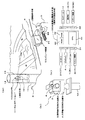
図1は、本発明の一実施の形態における計測装置の概略構成を示す図(図1(a)は該計測装置の斜視図、図1(b)はトータルステーションの斜視図、図1(c)は該計測装置における制御系のブロック図)である。
【0014】
本実施の形態において、計測装置は、切土及び盛土工事において円滑かつ迅速な施工に資する重要情報とされる土量変化率を早期かつ適時に得ることを目的として以下のように構成されている。
【0015】
即ち、計測装置は、図1に示すように、トータルステーション1と、操作手段たる遠隔操作手段2と、トータルステーション1に内蔵される旋回手段3と、画像撮影手段たるCCDカメラ4と、画像表示手段たるコンピュータ画面5と、視準位置表示手段6と、視準方向設定手段7と、データ伝送手段8とで構成されている。
【0016】
本計測装置において、トータルステーション1は、図1(a)に示すように、ノンプリズム型であって、測距機能及び測角機能を併せ持ち、斜距離、水平角、鉛直角の同時計測を可能とするものであり、本実施の形態において計測対象となる切土及び盛土工事の現場に面して、具体的には該現場全体の見通しが可能である急峻な斜面Sの途中において据付がされている。
【0017】
ここで、トータルステーション1は、崩落の虞が高い崖地にある急峻な斜面Sの途中に構築した鉄筋コンクリート架台11に固着した鋼製支持脚12に対し固定されており、これにより十分な計測精度の確保が可能となっている。鉄筋コンクリート架台11の上部は、更に計測すべき前方向を除いてフード部材13及び屋根部材14にて防護されている。尚、トータルステーション1は、一般的に使用される三脚の上に整準盤を介して設置することも可能である。
【0018】
また、遠隔操作手段2は、図1(c)に示すように、トータルステーション1の遠隔操作で視準方向の設定以外のものを行うものであり、コンピュータ22に対する入力手段である遠隔操作盤として機能するキーボード21と、コンピュータ22と、コンピュータ22からの出力信号をトータルステーション1まで伝送するデータ伝送手段8(図1(a)参照)とで構成されている。
【0019】
図1(c)において、キーボード21において行われる操作信号が入力インターフェース31を介して、コンピュータ22に入力されるようになっている。そして、このコンピュータ22は、中央演算処理装置(以下「CPU」という)41、ランダムアクセスメモリー(以下「RAM」という)42及びリードオンリーメモリー(以下「ROM」という)43からなり、ROM43には、トータルステーション1の測距及び測角等の遠隔操作を制御するプログラム(図示外)が格納されており、CPU41は、入力インターフェース31を介して、与えられた操作信号に基づいて前記プログラムを実行し、出力インターフェース32を介して、トータルステーション1の測距及び測角等の遠隔操作を制御する。
【0020】
更に、旋回手段3は、図1(b)に示すように、トータルステーション1の各部分であって、水平軸が支持される部分51を鉛直軸周りで旋回させると共に視準軸が支持される部分52を水平軸周りで旋回させるものであり、旋回機構及び駆動モータたる超音波などを使用した旋回駆動モータ(図示外)のほか、コンピュータ22からの操作信号を該超音波などを使用した旋回駆動モータへと伝送するデータ伝送手段8(図1(a)参照)が含まれる。尚、前記超音波を使用した旋回駆動モータは、小型かつ軽量で、大きな回転トルクが得られ微小の制御が容易であるという特長を有している。
【0021】
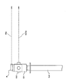
更にまた、CCDカメラ4は、図2に示すように、視準軸が支持される部分52と一体に設けられ、光軸4aが視準軸52aと一定間隔で平行に設定されるもので、コンピュータ画面5に対してリアルタイムで画像を供給するものである。尚、CCDカメラ4により得られた画像上には、後述するように、トータルステーション1が現に視準している位置の表示マークが表示されることになる。
【0022】
また、コンピュータ画面5は、図1(a)に示すように、CCDカメラ4にて撮影された画像を遠隔操作を行う箇所においてリアルタイムで表示するものである。これにより、機械操作者Oは、コンピュータ画面5を見ながらトータルステーション1の遠隔操作を行うことが可能になり、また、コンピュータ画面5上で計測範囲の設定やトータルステーション1の視準方向の設定をすることが可能になる。
【0023】
更に、視準位置表示手段6は、図1(c)に示すように、トータルステーション1が現に視準している計測対象上の点に対応する位置の表示マークをコンピュータ画面5の画像上において表示するものであり、コンピュータ22に対する入力手段として機能するトータルステーション1と、コンピュータ22と、コンピュータ22からの出力手段として機能するコンピュータ画面5とで構成されている。
【0024】
図1(c)において、トータルステーション1の計測(測距)データが入力インターフェース31を介して、コンピュータ22に入力されるようになっている。そして、ROM43には、画像上において表示される視準位置の表示マークの動きを制御するプログラム(図示外)が格納されており、CPU41は、入力インターフェース31を介して、与えられた測距データに基づいて前記プログラムを実行し、出力インターフェース32を介して、画像上において表示される視準位置の表示マークの動きを制御する。
【0025】
尚、このプログラムは、適宜タイミングでトータルステーション1による計測を行う度に、該計測により得られた測距データに対応した光軸4aと視準軸52aとのズレ量を画素数に換算すると共に、該画素数だけCCDカメラ4の光軸方向である画像中心点から下方に移動した部位において該表示マークを表示するものである。
【0026】
更にまた、視準方向設定手段7は、図1(c)に示すように、画像上で特定された位置に対応する計測対象上の点を視準するように旋回手段3の旋回動作を制御してトータルステーション1の視準方向の設定をするものであり、コンピュータ22に対する入力手段として機能するコンピュータ画面5と、コンピュータ22と、コンピュータ22からの出力手段として機能する旋回手段3とで構成されている。
【0027】
図1(c)において、コンピュータ画面5上で特定された位置の座標データが入力インターフェース31を介して、コンピュータ22に入力されるようになっている。ROM43には、画面上で特定された位置の座標データから該位置に対応する計測対象上の点を視準するように旋回手段3の旋回動作を制御するプログラム(図示外)が格納されており、CPU41は、入力インターフェース31を介して、与えられた座標データに基づいて前記プログラムを実行し、出力インターフェース32を介して、旋回手段3の旋回動作を制御する。
【0028】
即ち、本実施の形態では、コンピュータ22は、トータルステーション1の測距及び測角等の遠隔操作を制御する制御系として、また、画像上において表示される視準位置の表示マークの動きを制御する制御系として、更に、画面上で特定された位置の座標データから該位置に対応する計測対象上の点を視準するように旋回手段の旋回動作を制御する制御系として用いられることになる。
【0029】
更にまた、本実施の形態におけるデータ伝送手段8は、トータルステーション1の計測データをトータルステーション1の据付がされた箇所から遠隔操作を行う箇所まで伝送するほか、遠隔操作手段2においてコンピュータ22からの出力信号をトータルステーション1まで伝送し、旋回手段3においてコンピュータ22からの操作信号を超音波モータまで伝送するものであり、複数本の信号ケーブルを束ねたものとして構成されている。トータルステーション1の計測データを遠隔操作を行う箇所まで伝送するデータ伝送手段8の働きにより、トータルステーション1の据付がされた箇所から計測が終わる度に電子野帳を持ち帰る面倒が回避されることになる。
【0030】
次に、図1を用いて、本実施の形態に係る計測装置の作用について説明する。以下、トータルステーション1の据付における作用と、トータルステーション1を用いて行う計測における作用とに分けて説明する。
【0031】
(1)トータルステーション1の据付における作用
まず、トータルステーション1の据付に先立ち、急峻な斜面Sの途中の箇所において鉄筋コンクリート架台11(鋼製支持脚12を含む)の構築が行われる。即ち、掘削、基礎砕石、均しコンクリート、鋼製支持脚12の据付、鉄筋及び型枠の組立、コンクリートの打設、埋め戻し工等の各作業工程が順次行われる。
【0032】
次いで鋼製支持脚12に対してのトータルステーション1の据付が行われる。即ち、作業者(機械操作者Oであるか否かを問わない)により、トータルステーション1が鋼製支持脚12の頂部に設けられた据付板の上に載置されると共に、通常のトランシット等の測量機械と略同様の方法によって該据付板に対して固定される。
【0033】
(2)トータルステーション1を用いて行う計測における作用
本実施の形態では、トータルステーション1を用いて行う計測は切土及び盛土の出来形形状や土量変化率を早期かつ適時に求めることを目的として以下のように行われる。
【0034】
まず、機械操作者Oがキーボード21を用いて画像上において次に計測を行うべき位置を特定すると、コンピュータ画面5は特定された位置を座標データとして捉え、該座標データが入力インターフェース31を介して入力される。
【0035】
すると、CPU41は、与えられた座標データに基づいてプログラムを実行し、画像上で特定された次に計測を行うべき位置に対応する計測対象上の点を視準するように旋回手段3の旋回動作を制御する。
【0036】
その結果、機械操作者Oがトータルステーション1の据付箇所にいなくても、コンピュータ画面5と向き合う機械操作者Oによってトータルステーション1の視準方向の設定が行えることとなる。
【0037】
即ち、機械操作者Oが望遠鏡を直接覗きながら行う視準方向の設定を回避することができるので、これにより危険箇所における機械操作は、遠隔地から安全に行うことができ、崖地の崩落危険性から免れることができる。
【0038】
そして、トータルステーション1の視準方向の設定がされ、機械操作者Oがキーボード21を操作すると、該操作信号は入力インターフェース31を介して入力される。
【0039】
すると、CPU41は、与えられた操作信号に基づいてプログラムを実行し、トータルステーション1の測距及び測角等の計測動作を制御する。
【0040】
そして、計測動作によって得られた測距及び測角等の各計測データは、データ伝送手段8によってトータルステーション1の据付がされた箇所から遠隔操作を行う箇所まで伝送され、更に伝送されたの計測データが入力インターフェース31を介して入力される。
【0041】
すると、CPU41は、与えられた測距データに基づいてプログラムを実行し、コンピュータ画面5の画像上において表示される視準位置の表示マークの動きを制御することになる。
【0042】
以上説明したようなトータルステーション1を用いて行う計測の繰り返しによって蓄積される計測データは、電子野帳等をトータルステーション1の据付がされた箇所から計測作業が終わるごとに持ち帰る面倒もなく、早期かつ適時に土量変化率データに変換されることになり、本実施の形態において切土及び盛土工事の円滑かつ迅速な施工に寄与することになる。
【0043】
従って、本実施の形態に係る計測装置によれば、トータルステーション1の視準方向の設定を画像上において行うことができるので、崩落の虞のある急崖や法面から機械操作者Oの安全性が確保されることとなり、また、トータルステーション1による計測を自動で行うことができるので、従来の計測時における反射プリズムの持ち歩きによる苦渋作業から解放されることとなった。
【0044】
【発明の効果】
本発明に係る計測装置によれば、以上のように構成したため、危険な崖地や広域の土地造成工事に対する計測作業において、反射プリズムを持ち歩く等の苦渋作業を伴わず、安全性、迅速性の確保が可能になる。
【図面の簡単な説明】
【図1】本発明の一実施の形態における計測装置の概略構成を示す図(図1(a)は該計測装置の斜視図、図1(b)はトータルステーションの斜視図、図1(c)は該計測装置における制御系のブロック図)である。
【図2】本発明の一実施の形態における計測装置の構成要素のうち、主としてCCDカメラを示す側面図である。
【符号の説明】
1…トータルステーション
2…遠隔操作手段(操作手段)
3…旋回手段
4…CCDカメラ(画像撮影手段)
5…コンピュータ画面(画像表示手段)
6…視準位置表示手段
7…視準方向設定手段
8…データ伝送手段
11…鉄筋コンクリート架台
12…鋼製支持脚
13…フード部材
14…屋根部材
21…キーボード
22…コンピュータ
31…入力インターフェース
32…出力インターフェース
41…CPU(中央演算処理装置)
42…RAM(ランダムアクセスメモリー)
43…ROM(リードオンリーメモリー)
51…水平軸が支持される部分
52…視準軸が支持される部分
S…急峻な斜面
O…機械操作者[0001]
BACKGROUND OF THE INVENTION
The present invention relates to a measuring apparatus applied to various three-dimensional measurements such as geodetic, topographic measurement, steep cliff measurement, or construction surveying.
[0002]
[Prior art]
As a conventional measuring device of this type, for example, there is a total station that has both a distance measuring function and an angle measuring function, and can simultaneously measure oblique distance, horizontal angle and vertical angle, and automatically record measurement data in an electronic field book. A device composed of a target installed at a measurement point for distance measurement is known.
[0003]
According to this type of measuring device, it is possible to instantaneously obtain the three-dimensional coordinates of the measuring point where the target is installed, and to perform quantity management using a computer by using the measurement data recorded in the electronic field book In addition, errors and mistakes that are likely to occur when manually recording are reduced, and the reliability of measurement results can be improved.
[0004]
[Problems to be solved by the invention]
However, with this type of measuring device, when performing topographic measurements on dangerous cliffs or wide-area land preparation work, it is necessary to carry out the measurement work while carrying the reflecting prism. In such measurement work, manpower, cost and time are required. In addition, there is a problem that it is difficult to perform measurement with manned because there is a danger to human life in the measurement work in a place where there is a possibility of collapse of the natural ground.
[0005]
Therefore, an object of the present invention is to provide a measuring apparatus that can avoid troublesome work such as carrying a reflecting prism in topographic measurement work for dangerous cliffs and wide area land preparation work, and can ensure safety and speediness. There is.
[0006]
In order to solve the above-described object, a surveying instrument according to the present invention includes a non-prism type total station installed facing a measurement target, and an operation unit that performs operations other than setting the collimation direction by operating the total station. Turning means for turning each part of the total station, which supports the horizontal axis around the vertical axis, and turning a part where the collimation axis is supported around the horizontal axis, and the collimation axis An image photographing unit that is provided integrally with the supported portion and whose optical axis is set parallel to the collimation axis at a constant interval, and an image photographed by the image photographing unit in real time at the place where the operation is performed Based on the coordinate data of the image display means to be displayed and the position where the measurement is specified using the input means on the image, the point on the measurement object corresponding to the position is collimated Said rotary means is controlled to a quasi-direction setting means viewed for a set collimation direction of the total station, a position corresponding to a point on the measurement object, wherein the total station is collimated, vision displayed on the image Quasi-position display means .
[0007]
That is, the present invention includes a total station installed facing the measurement target, remote control means, turning means, image photographing means, image display means, collimation position display means, and collimation direction setting means, As a result, technical means to set the collimation direction of the total station on the image can be realized, and troublesome work such as carrying a reflecting prism can be avoided in topographic measurement work for dangerous cliffs and wide area land preparation work. It is possible to provide a measuring device that can ensure safety and speed.
[0008]
In such technical means, the optical axis direction of the image photographing means is displayed at the center of the image displayed by the image display means, that is, on the measurement object that is currently collimated by the total station. A point is also displayed at the approximate center of the image. However, since the optical axis of the image capturing means is set parallel to the collimation axis at a fixed interval, a deviation occurs between the point on the measurement target collimated by the total station and the center of the image. This deviation varies depending on the distance to the measurement target.
[0009]
Therefore, from the viewpoint of accurately grasping such a deviation and contributing to smooth measurement, a collimation position that displays on the image a position corresponding to a point on the measurement target collimated by the total station. It is preferable to provide a display means.
[0010]
On the other hand, the total station is a non-prism type that does not require a special sheet or prism for reflecting laser light, and has both a distance measuring function and an angle measuring function, and is capable of simultaneous oblique distance, horizontal angle, and vertical angle. If measurement and automatic recording of measurement data to an electronic field book, memory card, etc. are possible, mechanical structure such as whether it is a transit or theodolite, such as whether it uses electromagnetic waves or light waves, etc. No matter what.
[0011]
However, from the viewpoint of avoiding the trouble of bringing the electronic field book or the like from the location where the total station is installed every time measurement is completed, it is preferable to include data transmission means for transmitting measurement data.
[0012]
The operation of the total station in the present invention is automatically performed in a digital form in addition to mechanical operations performed on the total station for distance measurement and angle measurement (including horizontal angle and vertical angle). Includes everything from transmission of measurement data. Moreover, it does not ask | require whether it is remote control. However, the operation means in the present invention performs operations other than the setting of the collimation direction among the operations of the total station.
[0013]
DETAILED DESCRIPTION OF THE INVENTION
Hereinafter, the present invention will be described in detail based on embodiments shown in the accompanying drawings.
FIG. 1 is a diagram showing a schematic configuration of a measuring device according to an embodiment of the present invention (FIG. 1A is a perspective view of the measuring device, FIG. 1B is a perspective view of a total station, and FIG. 1C) FIG. 2 is a block diagram of a control system in the measurement apparatus.
[0014]
In the present embodiment, the measuring device is configured as follows for the purpose of obtaining an early and timely soil volume change rate, which is important information that contributes to smooth and rapid construction in cutting and banking work. .
[0015]
That is, as shown in FIG. 1, the measuring device is a
[0016]
In this measuring apparatus, the
[0017]
Here, the
[0018]
Further, as shown in FIG. 1 (c), the remote operation means 2 performs other than the collimation direction setting by remote operation of the
[0019]
In FIG. 1C, an operation signal performed on the
[0020]
Further, as shown in FIG. 1 (b), the turning means 3 is a part of the
[0021]
Further, as shown in FIG. 2, the CCD camera 4 is provided integrally with a
[0022]
Further, as shown in FIG. 1A, the
[0023]
Further, the collimation position display means 6 displays on the image of the computer screen 5 a display mark at a position corresponding to the point on the measurement target that the
[0024]
In FIG. 1C, the measurement (ranging) data of the
[0025]
This program converts the amount of deviation between the optical axis 4a corresponding to the distance measurement data obtained by the measurement and the
[0026]
Furthermore, the collimation direction setting means 7 controls the turning operation of the turning means 3 so as to collimate the point on the measurement object corresponding to the position specified on the image, as shown in FIG. The collimation direction of the
[0027]
In FIG. 1C, coordinate data at a position specified on the
[0028]
That is, in the present embodiment, the
[0029]
Furthermore, the data transmission means 8 in the present embodiment transmits the measurement data of the
[0030]
Next, the operation of the measuring apparatus according to the present embodiment will be described with reference to FIG. Hereinafter, the operation in the installation of the
[0031]
(1) Operation in Installation of
[0032]
Next, the
[0033]
(2) Operation in measurement performed using the
[0034]
First, when the machine operator O specifies the position where the next measurement should be performed on the image using the
[0035]
Then, the
[0036]
As a result, the collimation direction of the
[0037]
That is, the setting of the collimation direction performed by the machine operator O looking directly into the telescope can be avoided, so that the machine operation at the dangerous place can be safely performed from a remote place, and the risk of collapse of the cliff You can escape from sex.
[0038]
When the collimation direction of the
[0039]
Then, the
[0040]
Then, each measurement data such as distance measurement and angle measurement obtained by the measurement operation is transmitted from the place where the
[0041]
Then, the
[0042]
The measurement data accumulated by repeating the measurement performed using the
[0043]
Therefore, according to the measuring apparatus according to the present embodiment, the collimation direction of the
[0044]
【The invention's effect】
According to the measuring device according to the present invention, because it is configured as described above, in the measurement work for dangerous cliffs and wide-area land preparation work, it is safe and quick without carrying a difficult work such as carrying a reflecting prism. Securement becomes possible.
[Brief description of the drawings]
FIG. 1 is a diagram showing a schematic configuration of a measuring device according to an embodiment of the present invention (FIG. 1A is a perspective view of the measuring device, FIG. 1B is a perspective view of a total station, and FIG. 1C) FIG. 2 is a block diagram of a control system in the measurement apparatus.
FIG. 2 is a side view mainly showing a CCD camera among the components of the measuring apparatus according to the embodiment of the present invention.
[Explanation of symbols]
1 ...
3 ... turning means 4 ... CCD camera (image photographing means)
5. Computer screen (image display means)
6 ... collimation position display means 7 ... collimation direction setting means 8 ... data transmission means 11 ... reinforced
42 ... RAM (Random Access Memory)
43 ... ROM (Read Only Memory)
51: Part where horizontal axis is supported 52 ... Part where collimation axis is supported S: Steep slope O ... Machine operator
Claims (2)
前記トータルステーションの操作で視準方向の設定以外のものを行う操作手段と、
前記トータルステーションの各部分であって、水平軸が支持される部分を鉛直軸周りで旋回させ、視準軸が支持される部分を水平軸周りで旋回させる旋回手段と、
前記視準軸が支持される部分と一体に設けられ、光軸が前記視準軸と一定間隔で平行に設定される画像撮影手段と、
前記画像撮影手段にて撮影された画像を前記操作を行う箇所においてリアルタイムで表示する画像表示手段と、
前記画像上で入力手段を用いて特定された計測を行うべき位置の座標データに基づいて、該位置に対応する計測対象上の点を視準するように前記旋回手段を制御して前記トータルステーションの視準方向の設定をする視準方向設定手段と、
前記トータルステーションが視準している計測対象上の点に対応する位置を、前記画像上に表示する視準位置表示手段と、
を含むことを特徴とする、計測装置。A non-prism type total station installed facing the measurement object,
Operation means for performing operations other than the setting of the collimation direction in the operation of the total station;
Each part of the total station, a turning means for turning the part where the horizontal axis is supported around the vertical axis, and turning the part where the collimation axis is supported around the horizontal axis;
An image photographing means provided integrally with a portion where the collimation axis is supported, and an optical axis is set parallel to the collimation axis at a constant interval;
Image display means for displaying an image photographed by the image photographing means in real time at a place where the operation is performed;
Based on the coordinate data of the position to be measured specified on the image using the input means, the turning means is controlled so as to collimate the point on the measurement object corresponding to the position, and the total station Collimation direction setting means for setting a collimation direction ;
Collimation position display means for displaying on the image a position corresponding to a point on the measurement target that the total station collimates;
A measuring device comprising:
Priority Applications (1)
| Application Number | Priority Date | Filing Date | Title |
|---|---|---|---|
| JP14344599A JP4034005B2 (en) | 1999-05-24 | 1999-05-24 | Measuring device |
Applications Claiming Priority (1)
| Application Number | Priority Date | Filing Date | Title |
|---|---|---|---|
| JP14344599A JP4034005B2 (en) | 1999-05-24 | 1999-05-24 | Measuring device |
Publications (2)
| Publication Number | Publication Date |
|---|---|
| JP2000329553A JP2000329553A (en) | 2000-11-30 |
| JP4034005B2 true JP4034005B2 (en) | 2008-01-16 |
Family
ID=15338873
Family Applications (1)
| Application Number | Title | Priority Date | Filing Date |
|---|---|---|---|
| JP14344599A Expired - Fee Related JP4034005B2 (en) | 1999-05-24 | 1999-05-24 | Measuring device |
Country Status (1)
| Country | Link |
|---|---|
| JP (1) | JP4034005B2 (en) |
Families Citing this family (8)
| Publication number | Priority date | Publication date | Assignee | Title |
|---|---|---|---|---|
| KR20020097172A (en) * | 2001-02-08 | 2002-12-31 | 닛폰 고칸 가부시키가이샤 | Method for Measuring Three- dimensional Coordinate, Apparatus Thereof and Method for Building Large Construction Therewith |
| JP5133620B2 (en) * | 2006-07-03 | 2013-01-30 | タイワン インスツルメント カンパニー リミテッド | Surveying instrument |
| JP5127323B2 (en) * | 2006-07-03 | 2013-01-23 | タイワン インスツルメント カンパニー リミテッド | Surveying instrument |
| JP5028164B2 (en) * | 2006-07-03 | 2012-09-19 | タイワン インスツルメント カンパニー リミテッド | Surveying instrument |
| JP2008014682A (en) * | 2006-07-03 | 2008-01-24 | Pentax Industrial Instruments Co Ltd | Surveying instrument |
| JP5466807B2 (en) * | 2006-09-26 | 2014-04-09 | 株式会社トプコン | Laser scanner |
| JP5550853B2 (en) * | 2009-06-09 | 2014-07-16 | 株式会社ソーキ | Surveying device with image transmission function and surveying method |
| CN104460687B (en) * | 2013-09-17 | 2016-12-07 | 五冶集团上海有限公司 | A kind of total powerstation reflecting prism form remote control unit |
-
1999
- 1999-05-24 JP JP14344599A patent/JP4034005B2/en not_active Expired - Fee Related
Also Published As
| Publication number | Publication date |
|---|---|
| JP2000329553A (en) | 2000-11-30 |
Similar Documents
| Publication | Publication Date | Title |
|---|---|---|
| US9499952B2 (en) | System and method for providing information to operator of pile driver | |
| JP4309014B2 (en) | Construction machine control system with laser reference plane | |
| EP1591752B1 (en) | Measuring method and measuring system | |
| JP2916687B2 (en) | Automatic surveying equipment | |
| JP4034005B2 (en) | Measuring device | |
| WO2019197064A1 (en) | Construction machine guidance system | |
| JP6721925B1 (en) | Foundation pile construction support method and construction support system | |
| CN100378435C (en) | Electronic measuring device | |
| JP2001264059A (en) | Method of measuring displacement quantity of measured object | |
| JP2003119784A (en) | Pile driving system | |
| JPH0334805B2 (en) | ||
| JP2002131057A (en) | Jobsite measuring system | |
| EP1162317A2 (en) | Excavator for a ditch and excavating method therefor | |
| JP2943960B2 (en) | Position detection method | |
| JP4376401B2 (en) | Laser reference surface forming apparatus and construction machine control system | |
| JP2913512B2 (en) | Target for sending and receiving survey information | |
| JP2919273B2 (en) | Multifunctional surveying measurement system | |
| JP2590008B2 (en) | Automatic displacement measurement method for structures | |
| JPH093895A (en) | Device for controlling penetration amount of pile driving | |
| JP3146080B2 (en) | Excavator driving device | |
| JP6721224B1 (en) | Foundation pile construction support device | |
| WO2023008305A1 (en) | Survey setting point editing method, survey setting point editing device, and survey setting point editing program | |
| JP4422927B2 (en) | Survey method in civil engineering work | |
| JP4276900B2 (en) | Automatic survey system | |
| JPS6126443Y2 (en) |
Legal Events
| Date | Code | Title | Description |
|---|---|---|---|
| A621 | Written request for application examination |
Free format text: JAPANESE INTERMEDIATE CODE: A621 Effective date: 20050728 |
|
| A977 | Report on retrieval |
Free format text: JAPANESE INTERMEDIATE CODE: A971007 Effective date: 20070419 |
|
| A131 | Notification of reasons for refusal |
Free format text: JAPANESE INTERMEDIATE CODE: A131 Effective date: 20070425 |
|
| A521 | Written amendment |
Free format text: JAPANESE INTERMEDIATE CODE: A523 Effective date: 20070622 |
|
| A131 | Notification of reasons for refusal |
Free format text: JAPANESE INTERMEDIATE CODE: A131 Effective date: 20070718 |
|
| A521 | Written amendment |
Free format text: JAPANESE INTERMEDIATE CODE: A523 Effective date: 20070910 |
|
| TRDD | Decision of grant or rejection written | ||
| A01 | Written decision to grant a patent or to grant a registration (utility model) |
Free format text: JAPANESE INTERMEDIATE CODE: A01 Effective date: 20071017 |
|
| A61 | First payment of annual fees (during grant procedure) |
Free format text: JAPANESE INTERMEDIATE CODE: A61 Effective date: 20071024 |
|
| FPAY | Renewal fee payment (event date is renewal date of database) |
Free format text: PAYMENT UNTIL: 20101102 Year of fee payment: 3 |
|
| R150 | Certificate of patent or registration of utility model |
Free format text: JAPANESE INTERMEDIATE CODE: R150 |
|
| FPAY | Renewal fee payment (event date is renewal date of database) |
Free format text: PAYMENT UNTIL: 20111102 Year of fee payment: 4 |
|
| FPAY | Renewal fee payment (event date is renewal date of database) |
Free format text: PAYMENT UNTIL: 20111102 Year of fee payment: 4 |
|
| FPAY | Renewal fee payment (event date is renewal date of database) |
Free format text: PAYMENT UNTIL: 20121102 Year of fee payment: 5 |
|
| FPAY | Renewal fee payment (event date is renewal date of database) |
Free format text: PAYMENT UNTIL: 20121102 Year of fee payment: 5 |
|
| FPAY | Renewal fee payment (event date is renewal date of database) |
Free format text: PAYMENT UNTIL: 20131102 Year of fee payment: 6 |
|
| LAPS | Cancellation because of no payment of annual fees |