JP4422927B2 - Survey method in civil engineering work - Google Patents
Survey method in civil engineering work Download PDFInfo
- Publication number
- JP4422927B2 JP4422927B2 JP2001200693A JP2001200693A JP4422927B2 JP 4422927 B2 JP4422927 B2 JP 4422927B2 JP 2001200693 A JP2001200693 A JP 2001200693A JP 2001200693 A JP2001200693 A JP 2001200693A JP 4422927 B2 JP4422927 B2 JP 4422927B2
- Authority
- JP
- Japan
- Prior art keywords
- point
- civil engineering
- measured
- rangefinder
- operator
- Prior art date
- Legal status (The legal status is an assumption and is not a legal conclusion. Google has not performed a legal analysis and makes no representation as to the accuracy of the status listed.)
- Expired - Lifetime
Links
Images


Landscapes
- Arrangements For Transmission Of Measured Signals (AREA)
- Measurement Of Optical Distance (AREA)
- Optical Radar Systems And Details Thereof (AREA)
Description
【0001】
【発明の属する技術分野】
この発明は、土木工事の現場における出来形管理のための測量などに特に適した測量方法に関するものである。
【0002】
【従来の技術】
現在用いられている光波測距儀(この明細書では、単に測距儀と記す)には、被測定点に向けて照射した光ビームを被測定点に設けた反射ミラーで反射させ、この反射光によって種々の測定を行うプリズム式のものと、反射ミラーを用いないで被測定点に直接光ビームを当て、その点からの反射光を検出して測定するノンプリズム式のものとがある。前者にはミラーの移動に応じてミラーを自動的に追尾する自動追尾型測距儀も知られており、一度ミラーを視準した後は測距儀の操作者は不要で、被測定点側に1名の操作者が居ればいわゆるワンマン測量が可能である。また後者は測距儀の操作者が被測定点を視準することで測量を行うものであり、被測定点側の操作者は不要で測距儀の操作者だけでワンマン測量が可能である。
【0003】
しかしながら、土木工事の現場における出来形管理は、定期的な測量結果に応じて重機のオペレータに視認されやすい位置に板材などで目印を設置するいわゆる丁張り作業を行い、この目印に基づいて重機による加工作業を行うという手順を繰り返すことで行われている。このため、次回の測量までは正確な加工精度が判らず、しかも丁張り作業にかなりの時間を要すると共にその間は工事が中断されるために、工事の効率的な進行が妨げられるという問題点がある。また測量技術者を常時確保しておく必要があり、更に、工事現場は足場が悪くて危険な場所が多いためにミラーの操作者が立ち入ることができず、ミラー式の場合には測量が困難になることがある。
【0004】
【発明が解決しようとする課題】
この発明はこの点に着目し、ワンマン測量を可能にすると共に丁張り作業を不要とし、例えば重機のオペレータ自身が一人で測量を行いながら土木工事の加工作業を実施できるようにすることを課題としてなされたものである。
【0006】
【課題を解決するための手段】
上記の課題を達成するために、この出願の発明では、少なくとも、自動追尾型測距儀と、この測距儀に追尾の指示を行う遠隔制御手段と、光ビームを出力する投光器と、移動型コンピュータ、とを使用し、上記測距儀を3次元位置が既知な定点に設置して3次元位置が既知な基準点を視準させて測定することにより測距儀の位置と向きを確定し、次いで操作者が上記投光器を操作し、光ビームを上記基準点に当ててから被測定点まで移動してこれを測距儀に自動追尾させ、所定の測定を行って得られた被測定点のデータを上記測距儀から上記移動型コンピュータに転送してデータ処理することにより、上記基準点に関連付けて被測定点の3次元位置を算出するようにしている。従って、この方法により測距儀の設置後は一人の操作者が光ビームを操作してワンマン測量を行うことができる。なお、光ビームには、一般には可視光やレーザー光が用いられる。
【0007】
なお、上記の自動追尾型測距儀としては、追尾すべき光ビームを見失った時に所定の固定点を視準する状態に自動的に戻るものを使用することが望ましい。これによって、光ビームの追尾が不調に終わった場合でも測量を再開することができる。
【0010】
上記による3次元位置の算出結果を用いて、例えばあらかじめ移動型コンピュータに入力されている被測定点の設計位置との偏差を求めることができ、更にこの偏差をディスプレイ上に表示することができる。この表示は、単に数値データで示すこともできるが、例えば、設計上の断面図と被測定点の位置を示すマークとによって表示するようにすれば、偏差の大きさなどを視覚的に確認することができ、現状地形の把握が容易となる。またこのディスプレイを土木工事現場における重機に搭載しておけば、重機のオペレータが設計位置との偏差を確認しながら正確な加工作業を行うことが可能となる。
【0011】
【発明の実施の形態】
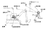
次にこの発明の実施の形態を説明する。図1は第1の発明を実施するためのシステムの基本構成を示している。図において、1は例えば可視光を出力する投光器2を備えているノンプリズム式の測距儀、2aは投光器2から出力される光ビーム、3は遠隔制御器、4は移動型コンピュータであり、測距儀1にはミラー式の場合よりも反射光の検出感度の高いものが使用される。投光器2はその投光軸が測距軸と平行になるように測距儀1に併設されている。なお、投光軸と測距軸とはその構造上数センチ離れることになるが、この差が問題になる場合には被測定点までの距離に応じて補正演算を行えばよい。
【0012】
移動型コンピュータ4としては、携帯や移動に適していて一般にモバイルコンピュータと称されているような各種の小型コンピュータ(以下、単にコンピュータと記す)が使用される。なお、遠隔制御器3はこのコンピュータ4で兼ねることができる。5はパワーショベルやブルドーザーなどの土木工事用重機、5aはその運転室を示している。コンピュータ4はこの運転室5aの適所に配置されるが、重機5のオペレータによるワンマン測量を行わない場合には他の場所に設置されてもよい。6aは測距儀1側に設けられている送受信器、6bはコンピュータ4側に設けられている送受信器であり、各種のデータや指令信号などを測距儀1とコンピュータ4との間で送受信するものである。なお、この送受信器6a、6bによる通信は電波を用いる無線通信で行われるが、他の媒体を用いた無線通信のほか、場合によっては有線通信で行うことも可能である。
【0013】
上述のシステムによる測量は次のように行われる。まず、測距儀1を3次元位置が既知な定点Aに設置し、その光ビーム2aを操作者、例えば重機5のオペレータが遠隔制御して3次元位置が既知な基準点Bに当て、その部分の岩石や土などからの反射光を測距儀1で検出して測定を行う。この測定は、水平角や高低角、斜距離などについて行い、測距儀1の位置と向きを確定する。なお基準点Bの視準は、遠隔制御ではなく操作者による直接操作で行ってもよい。次に、オペレータが遠隔制御器3を操作して測距儀1の光ビーム2aを被測定点Cに当てて測定の指示信号を送り、測距儀1が水平角、高低角、斜距離など必要な項目についての測定を行う。こうして得られた被測定点Cのデータは送受信器6a、6bによって測距儀1からコンピュータ4に転送され、コンピュータ4では受信したこれらのデータを処理し、基準点Bに対する相対的な位置から被測定点Cの3次元位置を算出するのである。
【0014】
コンピュータ4にはあらかじめ工事区域の設計値のデータが入力してあり、上記の算出された被測定点Cの3次元位置すなわち測定値と、被測定点Cの設計値との偏差が演算される。これらの測定値と偏差とは適宜コンピュータ4のメモリに記憶されるが、必要に応じてコンピュータ4のディスプレイに表示される。この表示は、単なる数値の表示だけではなく、例えば被測定点Cの位置を示すマークと、この位置における設計上の垂直断面図とを用いて表示される。なお、上記のディスプレイはコンピュータ4に付属しているものだけでなく、状況に応じて他のディスプレイを利用することもできる。
【0015】
図2はこのような表示画像の一例である。Dは設計上の断面図であり、被測定点Cはその位置を示すマークC1と、設計値との垂直方向の偏差を示す線C2、水平方向の偏差を示す線C3、設計斜面に対する垂線方向の偏差を示す線C4で表示されている。このような表示により、重機5のオペレータは設計値との偏差を視覚的に理解することができるので、作業を進めやすくなる。なお、上記の各線にそれぞれの偏差の数値を併記するようにすれば、偏差の大きさが具体的な数字によっても示されるので、より十分に状況を把握することができる。
【0016】
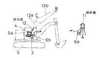
図3は第2の発明を実施するためのシステムの基本構成を示しており、11は自動追尾型の測距儀、12は投光器、12aは投光器12の光ビーム、12bは光ビーム12aが当たる位置の移動軌跡である。その他は図1と同様であり、同一の符号で示してある。測距儀11は投光器を備えていないノンプリズム式のものであり、ミラー式の場合よりも反射光の検出感度の高いものが使用される。また投光器12は可視光あるいはレーザー光を出力するもので、オペレータが手に持って操作できる小型軽量なものが使用される。
【0017】
このシステムによる測量は次のように行われる。まず、測距儀11を3次元位置が既知な定点Aに設置し、操作者が測距儀11を操作して3次元位置が既知な基準点Bを視準して測定を行い、測距儀11の位置と向きを確定する。この時の操作は視準操作に慣れた者が行うが、重機5のオペレータ自身が行うこともできる。次にオペレータが投光器12を操作し、その光ビーム12aを基準点Bに当ててから被測定点Cまで移動させる。測距儀11はこの光ビーム12aが当たる位置を自動追尾した後、被測定点Cに対する水平角、高低角、斜距離などの必要な項目についての測定を行う。こうして得られた被測定点Cのデータは、送受信器6a、6bによって測距儀11からコンピュータ4に転送され、コンピュータ4では受信したこれらのデータを処理し、基準点Bに対する相対的な位置から被測定点Cの3次元位置を算出するのである。以後の測定値や偏差の表示は上述した第1の発明の場合と同様である。
【0018】
なお、上記の自動追尾が不調に終わって測距儀11が光ビーム12aを見失った時には、所定の固定点、例えば、基準点Bを視準する状態に自動的に戻るようにしてある。従って、追尾動作が正常に行われなかった場合でも、再操作によって測量を行うことができる。
【0019】
各発明における定点Aと基準点Bは、作業区域外でしかも作業区域に近い地点で上述した所定の動作や操作が支障なく行える箇所が選定される。また、被測定点Cは操作者から見える地点が選定されるが、通常の作業の場合には重機5のオペレータが当面の作業の目標となる地点を選定し、作業の進捗に応じて被測定点Cを適宜移動しながら随時測量を行い、これを目標として作業を進めることになる。このように、測距儀1あるいは11を一旦設置した後は、重機5のオペレータは一人で測量を繰り返しながら作業を行うのである。
【0020】
図4は第3の発明を実施するためのシステムの基本構成を示しており、21は例えばCCD素子とこれに必要な制御部を備えることによって実現される撮像機能を搭載した測距儀、22は重機5の運転室5aの適所に配置された第2のディスプレイである。測距儀21は図3のシステムの場合と同様なノンプリズム式のものであり、撮像される画像中には画像の中心点を指示する軸心マークが重畳して表示され、この軸心マークと一致している部分が視準点となるように構成されている。また、測距儀21で撮像される画像は電気信号に変換されて送受信器6a、6bを介して重機5に伝送され、ディスプレイ22に再生表示されるように構成されている。なお、この第2のディスプレイ22はコンピュータ4のディスプレイで兼ねることもできる。その他は図1のシステムの場合と同様である。
【0021】
このシステムによる測量は次のように行われる。まず、測距儀21を3次元位置が既知な定点Aに設置し、遠隔操作あるいは直接操作により3次元位置が既知な基準点Bを視準し、基準点Bに対する水平角や高低角、斜距離などを測定して測距儀21の位置と向きを確定する。次に、重機5のオペレータがディスプレイ22に表示される画像を見ながら遠隔制御器3を操作して測距儀21の向きを制御し、測距儀21を被測定点Cに向ける。画像の中心には測定の軸心を示す例えば十字状の軸心マークが常に表示されているので、このマークと目標とする被測定点Cとを一致させた状態で測定の指示信号を送ると、測距儀21によって水平角、高低角、斜距離など必要な項目の測定が行われる。
【0022】
こうして得られた被測定点Cのデータは送受信器6a、6bによって測距儀21からコンピュータ4に転送され、コンピュータ4では受信したこれらのデータを処理し、基準点Bに対する相対的な位置から被測定点Cの3次元位置を算出するのである。以後の測定値や偏差の表示は上述した第1及び第2の発明の場合と同様である。通常のビデオカメラなどに準じた機能を測距儀21に搭載することは比較的容易であるから、光ビームが見えにくいなどの問題に煩わされることなく測定できる。また、被測定点Cが操作者から直接目視できる位置になくても測定できるので便利であり、実用性が向上する。
【0023】
【発明の効果】
以上の説明から明らかなように、この発明の測量方法は、自動追尾型測距儀を用いて、操作者が投光器の光ビームを操作して測距儀による測量を行い、その結果を移動型コンピュータで処理して被測定点の3次元位置を算出するようにしたものである。従って、丁張り作業が不要であり、測量技術者を常時配置しておく必要がなく、一人の操作者によるワンマン測量が可能となる。しかも必要に応じて随時被測定点を容易に測量できるので、高精度の作業を効率よく且つ安全に進めることができ、作業に要するコストも大幅に低減させることが可能となる。
【0025】
また、被測定点の算出された3次元位置と設計位置との偏差を求めてこれをディスプレイに表示することにより、偏差の大きさを確認することが容易となり、更に、設計上の断面図と被測定点の位置を示すマークとによって表示することにより、偏差の程度を視覚的に容易に確認することができる。また、土木工事現場における重機のオペレータが操作者となれば、作業の効率化が一層容易となる。
【図面の簡単な説明】
【図1】第1の発明を実施するためのシステムの基本構成を示す図である。
【図2】ディスプレイに表示される画像の一例を示す図である。
【図3】第2の発明を実施するためのシステムの基本構成を示す図である。
【図4】第3の発明を実施するためのシステムの基本構成を示す図である。
【符号の説明】
1、11、21 測距儀
2、12 投光器
2a、12a 光ビーム
3 遠隔制御器
4 移動型コンピュータ
5 重機
5a 運転室
6a、6b 送受信器
22 第2のディスプレイ
A 定点
B 基準点
C 被測定点[0001]
BACKGROUND OF THE INVENTION
The present invention relates to a surveying method that is particularly suitable for surveying and the like for finished shape management at a site of civil engineering work.
[0002]
[Prior art]
In the light wave range finder currently used (in this specification, simply referred to as a range finder), the light beam irradiated toward the measurement point is reflected by a reflection mirror provided at the measurement point, and this reflection is performed. There are a prism type that performs various measurements with light, and a non-prism type that measures light by directly applying a light beam to a measurement point without using a reflection mirror and detecting reflected light from that point. The former also has an automatic tracking rangefinder that automatically tracks the mirror according to the movement of the mirror. Once the mirror is collimated, no distancefinder operator is required, and the measured point side If there is one operator at a time, so-called one-man surveying is possible. In the latter case, the distance measuring operator collimates the point to be measured, and the operator on the side of the measured point is not required, and one-man measurement is possible with only the distance measuring operator. .
[0003]
However, the finished form management at the site of civil engineering works is a so-called tensioning work that installs a mark with a plate or the like at a position where it can be easily seen by an operator of the heavy machine according to a regular survey result. This is done by repeating the procedure of performing machining operations. For this reason, the exact processing accuracy is not known until the next survey, and it takes a considerable amount of time for the tightening work, and the work is interrupted during that time, which hinders efficient progress of the work. is there. In addition, it is necessary to keep a surveying engineer at all times. In addition, because the construction site is bad and there are many dangerous places, the mirror operator cannot enter, and in the case of the mirror type, surveying is difficult. May be.
[0004]
[Problems to be solved by the invention]
This invention pays attention to this point, and makes it possible to carry out a one-man survey and eliminate the need for a tightening work.For example, an operator of a heavy machine can carry out a civil engineering work while carrying out a survey alone. It was made.
[0006]
[Means for Solving the Problems]
In order to achieve the above object, in the invention of this application , at least an automatic tracking type distance measuring device, a remote control means for instructing the distance measuring device to track, a projector that outputs a light beam, and a movable type Using a computer, the position and orientation of the range finder are determined by placing the range finder at a fixed point with a known 3D position and collimating a reference point with a known 3D position. Then, the operator operates the projector, applies the light beam to the reference point, moves to the measurement point, and automatically tracks this to the rangefinder, and obtains the measurement point obtained by performing a predetermined measurement. This data is transferred from the distance measuring instrument to the mobile computer and processed, thereby calculating the three-dimensional position of the point to be measured in association with the reference point. Thus, after the installation of more rangefinder in this process can be carried out one-man surveying single operator operates the light beam. In general, visible light or laser light is used as the light beam.
[0007]
It is desirable to use an automatic tracking rangefinder that automatically returns to a state in which a predetermined fixed point is collimated when the light beam to be tracked is lost. As a result, the surveying can be resumed even when the tracking of the light beam ends unsuccessfully.
[0010]
Using the calculation result of the three-dimensional position according to the above, for example, a deviation from the design position of the measurement point input in advance to the mobile computer can be obtained, and this deviation can be displayed on the display. This display can be simply indicated by numerical data. For example, if the display is made with a design cross-sectional view and a mark indicating the position of the measured point, the magnitude of the deviation is visually confirmed. This makes it easier to understand the current topography. If this display is mounted on a heavy machine at a civil engineering work site, an operator of the heavy machine can perform an accurate machining operation while checking a deviation from the design position.
[0011]
DETAILED DESCRIPTION OF THE INVENTION
Next, an embodiment of the present invention will be described. FIG. 1 shows a basic configuration of a system for carrying out the first invention. In the figure, 1 is a non-prism range finder provided with a
[0012]
As the
[0013]
Surveying by the above-described system is performed as follows. First, the rangefinder 1 is set at a fixed point A whose three-dimensional position is known, and the
[0014]
The design value data of the construction area is input to the
[0015]
FIG. 2 is an example of such a display image. D is a cross-sectional view in design, and the point C to be measured is a mark C1 indicating the position, a line C2 indicating a vertical deviation from the design value, a line C3 indicating a horizontal deviation, and a direction perpendicular to the design slope This is indicated by a line C4 indicating the deviation. With such a display, the operator of the
[0016]
FIG. 3 shows a basic configuration of a system for carrying out the second invention. 11 is an automatic tracking type distance measuring probe, 12 is a projector, 12a is a light beam of the
[0017]
Surveying by this system is performed as follows. First, the ranging
[0018]
When the above-mentioned automatic tracking is not successful and the ranging
[0019]
As the fixed point A and the reference point B in each invention, a place where the above-described predetermined operation and operation can be performed without hindrance outside the work area and close to the work area is selected. Further, the point C to be measured is selected as a point that can be seen by the operator. However, in the case of normal work, the operator of the
[0020]
FIG. 4 shows the basic configuration of a system for carrying out the third invention.
[0021]
Surveying by this system is performed as follows. First, the
[0022]
The data of the measured point C thus obtained is transferred from the
[0023]
【The invention's effect】
As apparent from the above description, the surveying method of the present invention, by using the automatic tracking type distance meter performs surveying by rangefinder operator operates the light beam projectors, moving the result The three-dimensional position of the measurement point is calculated by processing with a type computer. Therefore, it is not necessary to place a surveying engineer at all times, and it is possible to perform one-man surveying by a single operator. In addition, since the measurement points can be easily measured as needed, highly accurate work can be carried out efficiently and safely, and the cost required for the work can be greatly reduced.
[0025]
In addition, by obtaining the deviation between the calculated three-dimensional position of the measured point and the design position and displaying it on the display, it is easy to check the magnitude of the deviation, By displaying with a mark indicating the position of the point to be measured, the degree of deviation can be easily confirmed visually. Further, if the operator of the heavy machinery at the civil engineering work site becomes the operator, the work efficiency can be further improved.
[Brief description of the drawings]
FIG. 1 is a diagram showing a basic configuration of a system for carrying out a first invention.
FIG. 2 is a diagram illustrating an example of an image displayed on a display.
FIG. 3 is a diagram showing a basic configuration of a system for carrying out a second invention.
FIG. 4 is a diagram showing a basic configuration of a system for carrying out a third invention.
[Explanation of symbols]
1, 11, 21
Claims (6)
Priority Applications (1)
| Application Number | Priority Date | Filing Date | Title |
|---|---|---|---|
| JP2001200693A JP4422927B2 (en) | 2001-03-21 | 2001-07-02 | Survey method in civil engineering work |
Applications Claiming Priority (3)
| Application Number | Priority Date | Filing Date | Title |
|---|---|---|---|
| JP2001-79692 | 2001-03-21 | ||
| JP2001079692 | 2001-03-21 | ||
| JP2001200693A JP4422927B2 (en) | 2001-03-21 | 2001-07-02 | Survey method in civil engineering work |
Publications (2)
| Publication Number | Publication Date |
|---|---|
| JP2002350134A JP2002350134A (en) | 2002-12-04 |
| JP4422927B2 true JP4422927B2 (en) | 2010-03-03 |
Family
ID=26611617
Family Applications (1)
| Application Number | Title | Priority Date | Filing Date |
|---|---|---|---|
| JP2001200693A Expired - Lifetime JP4422927B2 (en) | 2001-03-21 | 2001-07-02 | Survey method in civil engineering work |
Country Status (1)
| Country | Link |
|---|---|
| JP (1) | JP4422927B2 (en) |
Families Citing this family (1)
| Publication number | Priority date | Publication date | Assignee | Title |
|---|---|---|---|---|
| JP6539485B2 (en) * | 2015-04-21 | 2019-07-03 | 株式会社ミツトヨ | Measurement system using tracking type laser interferometer and recovery method thereof |
-
2001
- 2001-07-02 JP JP2001200693A patent/JP4422927B2/en not_active Expired - Lifetime
Also Published As
| Publication number | Publication date |
|---|---|
| JP2002350134A (en) | 2002-12-04 |
Similar Documents
| Publication | Publication Date | Title |
|---|---|---|
| US9453729B2 (en) | Layout equipment and layout method | |
| US7552539B2 (en) | Method and apparatus for machine element control | |
| US7742176B2 (en) | Method and system for determining the spatial position of a hand-held measuring appliance | |
| US7701566B2 (en) | Surveying system | |
| US6381006B1 (en) | Spatial positioning | |
| EP1503176A2 (en) | Survey guiding system | |
| JPH1047961A (en) | Control system and control method | |
| CN104380137A (en) | Method and handheld distance measurement device for indirect distance measurement by means of image-assisted angle determination function | |
| JP2006003119A (en) | Position measuring system | |
| US20110153167A1 (en) | Excavator control using ranging radios | |
| JPH032513A (en) | Automatic surveying equipment | |
| AU2016308671A1 (en) | A drill rig positioning and drill rod alignment system | |
| JP7341632B2 (en) | reflective target | |
| JP2021085770A (en) | Method, system and computer program for acquiring position information of mobile body | |
| JP4422927B2 (en) | Survey method in civil engineering work | |
| JP2913512B2 (en) | Target for sending and receiving survey information | |
| JP2831204B2 (en) | Mobile device positioning device | |
| JP2002005660A (en) | Remotely operated surveying system | |
| JP6667939B2 (en) | Rolling machine | |
| JP3015956B1 (en) | Method for measuring cylindrical features in surveying | |
| JP4477209B2 (en) | Direction angle measuring device for construction machinery | |
| JPH06100078B2 (en) | Automatic survey positioning system for tunnel lining machines | |
| JPH07113640A (en) | Method and equipment for measuring attitude of excavator by laser distance measurement | |
| JP2004150889A (en) | Remote operation type surveying vehicle, and remote operation type surveying system | |
| JP3295157B2 (en) | Shield surveying method |
Legal Events
| Date | Code | Title | Description |
|---|---|---|---|
| A521 | Written amendment |
Free format text: JAPANESE INTERMEDIATE CODE: A821 Effective date: 20050817 |
|
| A711 | Notification of change in applicant |
Free format text: JAPANESE INTERMEDIATE CODE: A711 Effective date: 20050817 |
|
| A521 | Written amendment |
Free format text: JAPANESE INTERMEDIATE CODE: A821 Effective date: 20050817 |
|
| A521 | Written amendment |
Free format text: JAPANESE INTERMEDIATE CODE: A523 Effective date: 20051017 |
|
| A621 | Written request for application examination |
Free format text: JAPANESE INTERMEDIATE CODE: A621 Effective date: 20070424 |
|
| A977 | Report on retrieval |
Free format text: JAPANESE INTERMEDIATE CODE: A971007 Effective date: 20090610 |
|
| A131 | Notification of reasons for refusal |
Free format text: JAPANESE INTERMEDIATE CODE: A131 Effective date: 20090616 |
|
| A521 | Written amendment |
Free format text: JAPANESE INTERMEDIATE CODE: A523 Effective date: 20090730 |
|
| TRDD | Decision of grant or rejection written | ||
| A01 | Written decision to grant a patent or to grant a registration (utility model) |
Free format text: JAPANESE INTERMEDIATE CODE: A01 Effective date: 20091110 |
|
| A01 | Written decision to grant a patent or to grant a registration (utility model) |
Free format text: JAPANESE INTERMEDIATE CODE: A01 |
|
| A61 | First payment of annual fees (during grant procedure) |
Free format text: JAPANESE INTERMEDIATE CODE: A61 Effective date: 20091207 |
|
| FPAY | Renewal fee payment (event date is renewal date of database) |
Free format text: PAYMENT UNTIL: 20121211 Year of fee payment: 3 |
|
| R150 | Certificate of patent or registration of utility model |
Free format text: JAPANESE INTERMEDIATE CODE: R150 Ref document number: 4422927 Country of ref document: JP Free format text: JAPANESE INTERMEDIATE CODE: R150 |
|
| FPAY | Renewal fee payment (event date is renewal date of database) |
Free format text: PAYMENT UNTIL: 20151211 Year of fee payment: 6 |
|
| R250 | Receipt of annual fees |
Free format text: JAPANESE INTERMEDIATE CODE: R250 |
|
| R250 | Receipt of annual fees |
Free format text: JAPANESE INTERMEDIATE CODE: R250 |
|
| R250 | Receipt of annual fees |
Free format text: JAPANESE INTERMEDIATE CODE: R250 |
|
| EXPY | Cancellation because of completion of term |