EP1591752B1 - Measuring method and measuring system - Google Patents
Measuring method and measuring system Download PDFInfo
- Publication number
- EP1591752B1 EP1591752B1 EP05008587.7A EP05008587A EP1591752B1 EP 1591752 B1 EP1591752 B1 EP 1591752B1 EP 05008587 A EP05008587 A EP 05008587A EP 1591752 B1 EP1591752 B1 EP 1591752B1
- Authority
- EP
- European Patent Office
- Prior art keywords
- measurement
- data
- image
- line
- measuring
- Prior art date
- Legal status (The legal status is an assumption and is not a legal conclusion. Google has not performed a legal analysis and makes no representation as to the accuracy of the status listed.)
- Not-in-force
Links
- 238000000034 method Methods 0.000 title claims description 10
- 238000005259 measurement Methods 0.000 claims description 121
- ATJFFYVFTNAWJD-UHFFFAOYSA-N Tin Chemical compound [Sn] ATJFFYVFTNAWJD-UHFFFAOYSA-N 0.000 claims description 23
- 238000012545 processing Methods 0.000 description 25
- 238000004364 calculation method Methods 0.000 description 14
- 238000013500 data storage Methods 0.000 description 10
- 230000003287 optical effect Effects 0.000 description 5
- 238000013507 mapping Methods 0.000 description 4
- 238000009412 basement excavation Methods 0.000 description 3
- 239000003086 colorant Substances 0.000 description 3
- 238000010586 diagram Methods 0.000 description 3
- 230000005540 biological transmission Effects 0.000 description 2
- 238000006243 chemical reaction Methods 0.000 description 2
- 238000010276 construction Methods 0.000 description 2
- 239000003550 marker Substances 0.000 description 2
- 239000002689 soil Substances 0.000 description 2
- 238000004891 communication Methods 0.000 description 1
- 230000001419 dependent effect Effects 0.000 description 1
- 239000004973 liquid crystal related substance Substances 0.000 description 1
- 238000007726 management method Methods 0.000 description 1
- 239000004065 semiconductor Substances 0.000 description 1
Images


Classifications
-
- G—PHYSICS
- G01—MEASURING; TESTING
- G01C—MEASURING DISTANCES, LEVELS OR BEARINGS; SURVEYING; NAVIGATION; GYROSCOPIC INSTRUMENTS; PHOTOGRAMMETRY OR VIDEOGRAMMETRY
- G01C15/00—Surveying instruments or accessories not provided for in groups G01C1/00 - G01C13/00
Definitions
- the present invention relates to a measuring method and a measuring system for measuring configuration of a surface such as a ground surface.
- a working plan drawing is prepared, and by taking the amount of graded soil and filling soil into account, the working plan is set up.
- the working plan drawing is prepared, actual conditions of the place of work is surveyed to set a reference for the working plan.
- Profile leveling is a leveling survey carried out along a centerline of the route.
- Cross sectioning is a leveling survey in a direction perpendicularly crossing the centerline (in a direction of the route).
- the cross-sectional profile prepared using the elevation of the stake head is merely a schematical drawing.
- a surveying instrument for acquiring surveying data is described in the Japanese Patent Application Publication No. 11-337336 .
- the present invention provides a measuring method according to claim 1.
- the present invention provides a measuring system according to claim.6.
- FIG. 1 and Fig. 2 general features of a measuring system according to the present invention will be described.
- the measuring system primarily comprises a surveying instrument 1 (e.g. a total station (TS)) for measuring distance, horizontal angle and up-to-bottom angle (vertical), an image pickup device 2 (e.g. a digital camera), a data processing device 3 such as a personal computer, a storage medium 5 such as a magnetic storage medium, a semiconductor storage medium, an optical storage medium, etc., measuring lines (a longitudinal sectional line 6 and a cross-sectional line 7) drawn on a ground surface of a measurement range, and at least two markers (reference stakes) 8 (to be described later) driven in the measurement range.
- a surveying instrument 1 e.g. a total station (TS)
- an image pickup device 2 e.g. a digital camera
- a data processing device 3 such as a personal computer
- a storage medium 5 such as a magnetic storage medium, a semiconductor storage medium, an optical storage medium, etc.
- measuring lines a longitudinal sectional line 6 and a cross-sectional line 7) drawn on
- the surveying instrument 1 performs surveying operation such as distance measurement and angle measurement in a range as required. Measurement data is recorded in the storage medium 5, and the measurement data in the storage medium 5 is inputted to the data processing device 3. An image of the measurement range or an image including the measurement range is taken by the image pickup device 2, and an image data (digital data) is recorded in the storage medium 5.
- the storage medium 5 is removable with respect to the image pickup device 2, and the storage medium 5 is also removable with respect to the surveying instrument 1 and the data processing device 3. By loading the storage medium 5 in the data processing device 3, the data processing device 3 can read out the image data recorded on the storage medium 5.
- the data processing device 3 synthesizes the image data with the measurement data, and these data are processed to turn to an image data with measurement data. Further, based on the image data with the measurement data, a longitudinal measurement data and a cross-sectional measurement data are obtained by calculation. Then, on a display unit 32 (to be described later), there are displayed a longitudinal sectional profile, a cross-sectional profile and a contour line chart of the surveying site, which are prepared based on the image data with the measurement data, the longitudinal measurement data and the cross-sectional measurement data.
- a user can have the image displayed as a 3-dimensional image or can pick up a measurement data relating to an arbitrary position in the image.
- Fig. 3 shows an example of the surveying instrument 1 used in the present invention.
- reference numeral 11 denotes a control arithmetic operation unit.
- a distance-measuring unit 12, a vertical angle measuring unit 13, a horizontal angle measuring unit 14, a storage unit 15, an operation/input unit 16, a display unit 17, and an input/output unit 18 are electrically connected to the control arithmetic operation unit 11.
- the control arithmetic operation unit 11 and the storage unit 15 make up together an arithmetic operation unit of the surveying instrument 1.
- the distance-measuring unit 12 comprises a light emitter 19 and a photodetector 21. From the light emitter 19, a distance-measuring light 25 is projected to an object to be measured (target for measurement) 24 via a projection optical system 22. A distance-measuring reflection light 26 reflected from the object to be measured 24 is received by the photodetector 21 via a photodetection optical system 23. Based on a photodetection signal issued from the photodetector 21, a distance to the object to be measured 24 is measured. It is designed in such manner that at least the light emitter 19, the photodetector 21, the projection optical system 22, and the photodetection optical system 23 are rotatably supported in horizontal and vertical directions. A horizontal angle and a vertical angle are measured by the vertical angle measuring unit 13 and the horizontal angle measuring unit 14 respectively, and the result of measurement is inputted to the control arithmetic operation unit 11.
- the storage unit 15 comprises a program storage unit and a data storage unit.
- the program storage unit stores a sequence program, a calculation program, etc. required for distance measurement and angle measurement.
- the data storage unit stores distance measurement data and angle measurement data. From the operation/input unit 16, conditions necessary for starting the distance measurement, a command to initiate distance measurement, etc. are inputted, and measuring conditions, progress of measurement and measurement results, etc. are displayed on the display unit 17.
- the input/output unit 18 controls connection with external devices and also controls transmitting and receiving of signals to and from external devices. For instance, data is written to the storage medium 5, or data recorded in the storage medium 5 is read out.
- the image pickup device 2 comprises an image pickup element such as a CCD.
- the image pickup device 2 is a digital camera, etc., for instance, which can output the pickup image as an electronic data.
- the image taken is turned to digital signals, and these are recorded in the storage medium 5 such as a memory card, or the signals can be outputted to outside.
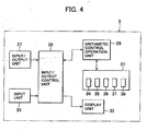
- the data processing device 3 comprises an input/output unit 27, an input/output control unit 28, an arithmetic operation control unit (CPU) 29, a storage unit 31 such as a hard disk, a display unit 32 such as a liquid crystal display, and an input unit 33 such as a keyboard, etc.
- the input/output control unit 28, the arithmetic operation control unit 29, and the storage unit 31 make up together an arithmetic operation unit of the data processing device 3.
- the input/output unit 27 reads out the data recorded in the storage medium 5 and writes the data to the recording medium 5, and the data are given to or taken from the arithmetic operation control unit 29 via the input/output control unit 28.
- the storage unit 31 programs such as an image processing program 34 for image processing, a data processing program 35, a measurement data calculating program 36, an image reproducing program 37, etc. are stored, and the storage unit 31 has a data storage unit 38 which stores data such as data from the input/output control unit 28 and calculation data calculated at the arithmetic operation control unit 29.
- a broken line represents configuration of the ground surface.
- the surveying instrument 1 is set at a known point, and a machine height of the surveying instrument 1 is measured (Step 01 and Step 02).
- a traverse (or a cross-sectional) line 7 (a straight line) is drawn on the ground surface of a portion to be measured (Step 03).
- Reference stakes 8, serving as markers, are driven at least at two points (more preferably at three points or more) along the cross-sectional line 7 (Step 04).
- the marker is not limited to the reference stake, and any object may be selected and used so far as it serves as a target for measurement.
- the reference stakes 8 should be driven in such manner that upper surfaces of the reference stakes 8 are maintained at a constant height from the ground surface. Also, it is preferable that cross lines or spots, etc. are marked on the upper surfaces of the reference stakes 8. The upper surface of the reference stake 8, or more preferably, an intersection of the cross lines or the spot, is used as an a control point (to be described later).
- An image is taken in the range including the cross-sectional line 7 by the image pickup device 2 approximately from a direction of the surveying instrument, and the image is recorded as an image data 41 in the storage medium 5 (Step 05).
- the image data 41 may be limited to a required width including the cross-sectional line 7 (a width including measurement lines 42 and 42 as described later).
- the storage medium 5 is loaded in the input/output unit 27 of the data processing device 3, and the image data 41 is stored in the data storage unit 38. Or, the storage medium 5 may be loaded in the input/output unit 18 of the surveying instrument 1, and measurement may be made.
- Measurement is made on the reference stakes 8a, 8b and 8c (measurement of a distance, a horizontal angle and an elevation angle of the control point) by using the surveying instrument 1 (Step 06).
- the measurement lines 42 and 43 are set on the program in such range as to include the cross-sectional line 7, and normally in a width to include the cross-sectional line 7.
- measuring points 44a, 44b, « and measuring points 45a, 45b, « are automatically measured at predetermined intervals along the measurement lines 42 and 43.
- Measurement data 46 are acquired (Step 07), and the measurement data 46 are recorded in the storage medium 5.
- the storage medium 5 is loaded in the input/output unit 27 of the data processing device 3, and the measurement data 46 are stored in the data storage unit 38.
- the image processing program 34 and the data processing program 35 are started.
- the image data 41 and the measurement data 46 are superimposed on each other, and a superimposed data 49 is prepared.
- the image data 41 and the measurement data 46 are superimposed on each other in such manner that the reference stakes 8a, 8b, and 8c in the image data 41 match with the reference stakes 8a, 8b and 8c in the measurement data 46 using the reference stakes 8a, 8b, and 8c as control points.
- the image is superimposed on a mesh which is formed by the measuring points.
- the measurement data calculating program 36 is started. On the assumption that the cross-sectional line 7 is a straight line, equations of straight lines 47a, 47b and 47c connecting two points which interpose the cross-sectional line 7 therebetween are calculated from the measurement data 46 of the measuring points 44a, 44b and the measuring points 45a and 45b which interpose the cross-sectional line 7 therebetween. Intersections 48a, 48b and 48c of the straight lines 47a, 47b and 47c and the cross-sectional line 7 are obtained from the superimposed data 49. Measurement data of the intersections 48a, 48b and 48c is calculated from the equations of the straight lines 47a, 47b and 47c. The intersection is set at a predetermined position of a width of the cross-sectional line 7, e.g. at a width center of the cross-sectional line 7, and the width center can be obtained from the image data 41.
- a cross-sectional curve 50 is calculated based on the data of height among the data of the intersections. Based on the cross-sectional curve 50, a cross-sectional profile 40 is prepared by the image processing program 34 (Step 10). The cross-sectional profile 40 shows cross-sectional configuration with respect to the cross-sectional line 7.
- the cross-sectional profile 40 is displayed on the display unit 32 by the image reproducing program 37.
- An operator in charge of measurement can identify the cross-sectional configuration at the cross-sectional line 7 from the cross-sectional profile 40 displayed on the display unit 32. Further, the cross-sectional profiles 40 are obtained on a plurality of cross-sectional lines 7. By displaying the cross-sectional profiles 40 on the same screen, the changing conditions of cross-sections can be visually recognized.
- intersections of a plurality of cross-sectional lines 7 with the longitudinal sectional line 6 at the predetermined position are obtained.
- the measurement data at intersections on the cross-sectional lines 7 from the cross-sectional curve 50, it is also possible to obtain a longitudinal sectional profile along the longitudinal sectional line 6 at the predetermined position.
- measurement lines are set on both sides of the longitudinal sectional line 6, and measurement and calculation are made in a manner similar to the case of the cross-sectional line 7, and the cross-sectional line 7 and the longitudinal section can be obtained.
- a flexible rope, a belt or a string, etc. may be placed in a straight line on the ground surface.
- the storage unit 31 of the data processing device 3 there are stored an image processing program 34, a data processing program 35, a measurement data calculating program 36, an image reproducing program 37, etc.
- the image processing program 34 superimposes TIN data 57 with a pickup image and performs image processing such as conversion from a pickup image 51 which is superimposed with TIN data (one point transmission image)(See Fig.10 ) to an orthogonal projection image 52 (ortho-image) or conversion from an ortho-image to an one point transmission image.
- the data processing program 35 performs data processing such as processing of the image data on the measurement data by texture mapping.
- the measurement data calculating program 36 obtains measurement data at an arbitrary point on the image from synthesized data of the image data and the measurement data by interpolation of mesh data.
- the image reproducing program 37 calculates an image as seen from an arbitrary direction.
- the storage unit 31 has a data storage unit 38 to store data such as data from the input/output control unit 28 and calculation data calculated at the arith
- Each of the programs as described above is started by the input from the input unit 33, and calculation is made. For instance, on the display unit 32, an image prepared by texture mapping of the measurement data and the image data is displayed. When an arbitrary point in the image is specified, the measurement data calculating program 36 is started, and the data such as positional data, elevation, tilting, etc. of the specified point are calculated and displayed.
- the surveying instrument 1 is set up at a known point, and machine height of the surveying instrument 1 is measured (Step 01 and Step 02).
- a cross-sectional line 7 (a straight line) is drawn on the ground surface of the object to be measured (Step 03).
- Reference stakes 8a, 8b and 8c, serving as markers, are driven at least at two point (more preferably, at three points or more) along the cross-sectional line 7 (Step 04).
- the reference stakes 8a, 8b and 8c should be set up in such manner that upper surfaces of the reference stakes 8a, 8b and 8c are positioned at a predetermined height from the ground surface. Also, it is preferable that cross lines or a spot, etc. are marked on the upper surfaces of the reference stakes 8a, 8b and 8c.
- the upper surface of the reference stakes 8a, 8b, and 8c, or more preferably, an intersection of the cross lines or the spot, is used as a control point (to be described later).
- the image of the range including the cross-sectional line 7 is taken by the image pickup device 2 from a direction tilted with respect to the cross-sectional line 7, and the image is recorded as an image data 41 in the storage medium 5.
- a range including the cross-sectional line 7 is designated as a measurement range 55 by the surveying instrument 1.
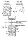
- measurement are performed. Further, measuring points are automatically measured (See Fig. 12 and Fig. 13(A) . In the figures, all intersections indicate measuring points.) with a predetermined interval in the measurement range 55 (Step 07 and Step 11).
- the data at the measuring points, the data of distance measurement, and data of horizontal and vertical angles are recorded in the storage medium 5 via the input/output unit 18.
- the measurement data 46 can be inputted to the data processing device 3 via the storage medium 5.
- the measurement data 46 of the storage medium 5 are read out and are recorded as working data into the data storage unit 38.
- the data processing program 35 is started.
- the measurement data 46 are connected using the measuring points as vertexes and are turned to TIN data 57, which represents a collective body of triangular planes named TIN (triangular indefinite net) (See Fig. 13 (A) ) (Step 12).
- TIN triangular indefinite net
- Each of the measuring points as described above has 3-dimensional data including planar position and height.
- a coordinate calculation equation to indicate a triangular plane with three measuring points as vertexes can be calculated based on 3-dimensional data of the three measuring points, and 3-dimensional data at an arbitrary position in the triangular plane can be calculated from the coordinate calculation equation.
- the coordinate calculation equation is described, for instance, in the Japanese Patent Application Publication No. 2004-163292 .
- the TIN data 57 and the coordinate calculation equation to indicate the triangular planes (hereinafter referred as "mesh") are stored in the data storage unit 38 together with the measurement data 46 as working data.
- the pickup image 51 is outputted as the digital image data 41, and the image data 41 is recorded in the storage medium 5.
- the storage medium 5 is taken out of the image pickup device 2 and is loaded to the data processing device 3.
- the image data 41 is inputted to the data processing device 3 via the storage medium 5.
- the image data 41 in the storage medium 5 is read out and is stored in the data storage unit 38.
- the image processing program 35 is started. It is designed in such manner that the reference point (control point) measured by the surveying instrument 1 matches the control point of the pickup image 51. Based on this, an image corresponding to each TIN (triangular net) is processed by texture mapping, and a superimposed measurement data with an image superimposed on it is prepared (Step 14).
- the data are developed on the ortho-image 58 (Step 15).
- the image is expanded or reduced in size to match the expansion or the reduction of TIN.
- the pickup image 51 thus converted corresponds to the point in the figure of the TIN data 57 on 1:1 basis (See Fig. 13 ).
- the ortho-image 58 is an image including 3-dimensional data.
- the TIN data 57 and the pickup image 51 may be linked to each other for each measurement range or for each mesh in the measurement range.
- the TIN data 57 and the pickup image 51 may be stored in different storage areas and may be linked together by management data. Or, different storage area may be used for each mesh, and the data relating to one mesh of the TIN data 57 and image data corresponding to one mesh of the pickup image 51 may be stored in different storage areas respectively.
- the measurement data calculating program 36 is started, and TINs in the ortho-image 58 including the cross-sectional line 7 are selected. From the coordinate calculation equation of the TIN, the measurement data of the cross-sectional line 7 is calculated. When the measurement data of the cross-sectional line 7 are calculated for all of the TINs including the cross-sectional line 7, measurement data for total length of the cross-sectional line 7 can be obtained (Step 16).
- the measuring point in the TIN of the cross-sectional line 7 is at a predetermined position of the width of the cross-sectional line 7, e.g. a width center of the cross-sectional line 7.
- a across-sectional curve 50 is calculated based on height data among the measurement data of the cross-sectional line 7. Based on the cross-sectional curve 50, a cross-sectional profile 40 (See Fig. 9 ) is prepared by the image processing program 34 (Step 17).
- the cross-sectional profile 40 is displayed on the display unit 32 by the image reproducing program 37. Further, cross-sectional profiles 40 for a plurality of cross-sectional lines 7 are obtained. By displaying the cross-sectional profiles 40 on the same screen, the changing condition of the cross-sections can be visually recognized.
- intersections of a plurality of the cross-sectional lines 7 with the longitudinal sectional line 6 at the predetermined position are obtained on the image data 41 and when the measurement data of the intersections on the cross-sectional line 7 are obtained from the cross-sectional curve 50, it is possible to have a longitudinal sectional profile along the longitudinal sectional line 6 at the predetermined position.
- the storage medium 5 By writing the associated data (working data) to the storage medium 5, the storage medium 5 can be used as an electronic working data.
- the image processing program 34, the measurement data calculating program 36, and the image reproducing program 37 are stored in the storage unit 15 of the surveying instrument 1, it is possible to display the ortho-image 58 on the display unit 17 of the surveying instrument 1 by loading the storage medium 5, where the working data is recorded, into the input/output unit 18.
- the image processing program 34, the measurement data calculating program 36, and the image reproducing program 37 are stored in the storage unit 15 of the surveying instrument 1, it is possible to display the ortho-image 58 on the display unit 17 of the surveying instrument 1 by loading the storage medium 5, where the working data is recorded, into the input/output unit 18.
- programs similar to the programs in the storage unit 31 into the storage unit 15 of the surveying instrument 1 it is possible to prepare the working data by the surveying instrument 1 itself.
- working result data obtained through the execution of the work are sequentially recorded and accumulated, and these are acquired as the finishing data.
- the finishing data of civil engineering work are compared with the working data, and the results of comparison are displayed on the display unit 32.
- Fig. 14 shows an executed work image 59 where poorly worked portion and unworked portion in the comparison results are displayed.
- the scope of working is displayed, and it is also displayed whether the scope of working is excavation work or it is soil-filling work.
- the scope of excavation 61 and the scope of soil-filling 62 are displayed in different colors so that these can be visually recognized.
- the marker provided on the line is not limited to the reference stake 8 and anything may be used so far as it can be measured and can be recognized on photograph.
- the reference stake 8 may be placed at a position other than the cross-sectional line 7 so far as it can serve as a reference for the superimposing of the image data 41 on the measurement data 46.
Description
- The present invention relates to a measuring method and a measuring system for measuring configuration of a surface such as a ground surface.
- In a working project to construct a route or the like, a working plan drawing is prepared, and by taking the amount of graded soil and filling soil into account, the working plan is set up. When the working plan drawing is prepared, actual conditions of the place of work is surveyed to set a reference for the working plan.
- For the purpose of carrying out the construction of a route, longitudinal sectional surveying (profile leveling) and cross-sectional surveying (cross sectioning) are performed. Profile leveling is a leveling survey carried out along a centerline of the route. Cross sectioning is a leveling survey in a direction perpendicularly crossing the centerline (in a direction of the route).
- In the past, when profile leveling is carried out, stakes with numbers marked on the stakes are driven along a centerline, and elevation of the stake head of the driven stakes with numbers and height of the ground are measured. By measuring the height of the stake head, height and tilting of the ground can be calculated. When cross sectioning is performed, stakes are driven at predetermined intervals along a straight line, which runs perpendicularly to the route. By measuring the elevation of the stake head of the stake, the height of the ground is measured. By measuring the height of the stake head, the height of the ground can be calculated. Based on the results of surveying, a cross-sectional profile (lateral profile) indicating the cross-sectional height is prepared.
- For both of profile leveling and cross sectioning, it is necessary to drive stakes for performing surveying. Intervals between stakes are determined by topographical conditions. To drive stakes with too small interval simply means the increase of work and is not adequate. Therefore, the stakes are driven at such a interval as not to place excessive burden on operators. For this reason, in the topographical conditions with extreme ups and downs, the elevation of the stake does not accurately represent actual condition of the ups and downs. Thus, the cross-sectional profile prepared using the elevation of the stake head is merely a schematical drawing. When the stake head is surveyed and the cross-sectional profile is prepared from the height of the stake head, it is assumed that the height of the stake head from the ground surface is at a constant level. If it is not constant, it is not possible to prepare accurate cross-sectional profile. However, it is not very easy to drive many stakes at a constant height. In case of a large-scale working project, long time is required and it is difficult to prepare an accurate cross-sectional profile.
- A surveying instrument for acquiring surveying data is described in the Japanese Patent Application Publication No.
11-337336 - It is an object of the present invention to provide a measuring system, by which it is possible.to perform accurate profile leveling and cross sectioning within shot time and without giving much burden on an operator.
- To attain the above object, the present invention provides a measuring method according to
claim 1. - Also, the present invention provides a measuring system according to claim.6.
- Preferred embodiments are specified in the dependent claims.
-
- Fig. 1
- is a drawing to explain an embodiment of the present invention;
- Fig. 2
- is a schematical block diagram of a measuring system according to the present invention;
- Fig. 3
- is a schematical block diagram of a surveying instrument of the measuring system according to the present invention;
- Fig. 4
- is a block diagram of a data processing device of the measuring system according to the present invention;
- Fig. 5
- is a flow chart showing operation in a first embodiment of the present invention;:
- Fig. 6
- is a drawing to show relation between an image pickup device and an image data in the first embodiment of the present invention;
- Fig. 7
- is a drawing to show relation between a surveying instrument and a measuring data;
- Fig. 8
- is a drawing to explain a condition where an image data is superimposed on a measurement data in the first embodiment of the present invention;
- Fig. 9
- is a drawing to explain a cross-sectional curve obtained in the first embodiment of the present invention;
- Fig. 10
- represents drawings to show relation between a pickup image and an ortho-image in a second embodiment of the present invention;
- Fig. 11
- is a drawing to explain relation among a measurement range, a surveying instrument and an image pickup device in the second embodiment of the present invention;
- Fig. 12
- is a drawing to show relation between a measurement data and a surveying instrument in the second embodiment of the present invention;
- Fig. 13
- represents drawings to explain image processing of a TIN data, a pickup image and an ortho-image in the second embodiment of the present invention; and
- Fig. 14
- is a drawing to show an example, in which civil engineering working data is superimposed on finishing data.
- Description will be given below on the best mode of the invention to carry out the present invention referring to the drawings.
- Referring to
Fig. 1 andFig. 2 , general features of a measuring system according to the present invention will be described. - The measuring system primarily comprises a surveying instrument 1 (e.g. a total station (TS)) for measuring distance, horizontal angle and up-to-bottom angle (vertical), an image pickup device 2 (e.g. a digital camera), a
data processing device 3 such as a personal computer, astorage medium 5 such as a magnetic storage medium, a semiconductor storage medium, an optical storage medium, etc., measuring lines (a longitudinalsectional line 6 and a cross-sectional line 7) drawn on a ground surface of a measurement range, and at least two markers (reference stakes) 8 (to be described later) driven in the measurement range. - The
surveying instrument 1 performs surveying operation such as distance measurement and angle measurement in a range as required. Measurement data is recorded in thestorage medium 5, and the measurement data in thestorage medium 5 is inputted to thedata processing device 3. An image of the measurement range or an image including the measurement range is taken by theimage pickup device 2, and an image data (digital data) is recorded in thestorage medium 5. Thestorage medium 5 is removable with respect to theimage pickup device 2, and thestorage medium 5 is also removable with respect to the surveyinginstrument 1 and thedata processing device 3. By loading thestorage medium 5 in thedata processing device 3, thedata processing device 3 can read out the image data recorded on thestorage medium 5. - The
data processing device 3 synthesizes the image data with the measurement data, and these data are processed to turn to an image data with measurement data. Further, based on the image data with the measurement data, a longitudinal measurement data and a cross-sectional measurement data are obtained by calculation. Then, on a display unit 32 (to be described later), there are displayed a longitudinal sectional profile, a cross-sectional profile and a contour line chart of the surveying site, which are prepared based on the image data with the measurement data, the longitudinal measurement data and the cross-sectional measurement data. - A user can have the image displayed as a 3-dimensional image or can pick up a measurement data relating to an arbitrary position in the image.
- Now, detailed description will be given on devices, which constitute the measuring system.
-
Fig. 3 shows an example of the surveyinginstrument 1 used in the present invention. - In
Fig. 3 ,reference numeral 11 denotes a control arithmetic operation unit. A distance-measuringunit 12, a verticalangle measuring unit 13, a horizontalangle measuring unit 14, astorage unit 15, an operation/input unit 16, adisplay unit 17, and an input/output unit 18 are electrically connected to the controlarithmetic operation unit 11. The controlarithmetic operation unit 11 and thestorage unit 15 make up together an arithmetic operation unit of the surveyinginstrument 1. - The distance-measuring
unit 12 comprises alight emitter 19 and aphotodetector 21. From thelight emitter 19, a distance-measuringlight 25 is projected to an object to be measured (target for measurement) 24 via a projectionoptical system 22. A distance-measuring reflection light 26 reflected from the object to be measured 24 is received by thephotodetector 21 via a photodetectionoptical system 23. Based on a photodetection signal issued from thephotodetector 21, a distance to the object to be measured 24 is measured. It is designed in such manner that at least thelight emitter 19, thephotodetector 21, the projectionoptical system 22, and the photodetectionoptical system 23 are rotatably supported in horizontal and vertical directions. A horizontal angle and a vertical angle are measured by the verticalangle measuring unit 13 and the horizontalangle measuring unit 14 respectively, and the result of measurement is inputted to the controlarithmetic operation unit 11. - The
storage unit 15 comprises a program storage unit and a data storage unit. The program storage unit stores a sequence program, a calculation program, etc. required for distance measurement and angle measurement. The data storage unit stores distance measurement data and angle measurement data. From the operation/input unit 16, conditions necessary for starting the distance measurement, a command to initiate distance measurement, etc. are inputted, and measuring conditions, progress of measurement and measurement results, etc. are displayed on thedisplay unit 17. - The input/
output unit 18 controls connection with external devices and also controls transmitting and receiving of signals to and from external devices. For instance, data is written to thestorage medium 5, or data recorded in thestorage medium 5 is read out. - The
image pickup device 2 comprises an image pickup element such as a CCD. Theimage pickup device 2 is a digital camera, etc., for instance, which can output the pickup image as an electronic data. The image taken is turned to digital signals, and these are recorded in thestorage medium 5 such as a memory card, or the signals can be outputted to outside. - As shown in
Fig. 4 , thedata processing device 3 comprises an input/output unit 27, an input/output control unit 28, an arithmetic operation control unit (CPU) 29, astorage unit 31 such as a hard disk, adisplay unit 32 such as a liquid crystal display, and aninput unit 33 such as a keyboard, etc. The input/output control unit 28, the arithmeticoperation control unit 29, and thestorage unit 31 make up together an arithmetic operation unit of thedata processing device 3. - The input/
output unit 27 reads out the data recorded in thestorage medium 5 and writes the data to therecording medium 5, and the data are given to or taken from the arithmeticoperation control unit 29 via the input/output control unit 28. - In the
storage unit 31, programs such as animage processing program 34 for image processing, adata processing program 35, a measurementdata calculating program 36, animage reproducing program 37, etc. are stored, and thestorage unit 31 has adata storage unit 38 which stores data such as data from the input/output control unit 28 and calculation data calculated at the arithmeticoperation control unit 29. - Based the input from the
input unit 33, various types of programs described above are started, and calculation is carried out. Conditions of processing, calculation results, etc. are displayed on thedisplay unit 32. - Referring to
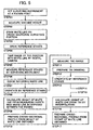
Fig. 5 to Fig. 9 , as a first embodiment of the present invention, description will be given now on an embodiment of a simple case. The following description is given on a case where cross-sectional measurement is carried out. InFig. 7 , a broken line represents configuration of the ground surface. - The surveying
instrument 1 is set at a known point, and a machine height of the surveyinginstrument 1 is measured (Step 01 and Step 02). - A traverse (or a cross-sectional) line 7 (a straight line) is drawn on the ground surface of a portion to be measured (Step 03).
- To facilitate the distinction from the ground surface, it is preferable to select and use colors like white color, yellow color, etc.
-
Reference stakes 8, serving as markers, are driven at least at two points (more preferably at three points or more) along the cross-sectional line 7 (Step 04). - In this case, the marker is not limited to the reference stake, and any object may be selected and used so far as it serves as a target for measurement.
- The reference stakes 8 should be driven in such manner that upper surfaces of the
reference stakes 8 are maintained at a constant height from the ground surface. Also, it is preferable that cross lines or spots, etc. are marked on the upper surfaces of the reference stakes 8. The upper surface of thereference stake 8, or more preferably, an intersection of the cross lines or the spot, is used as an a control point (to be described later). - An image is taken in the range including the
cross-sectional line 7 by theimage pickup device 2 approximately from a direction of the surveying instrument, and the image is recorded as animage data 41 in the storage medium 5 (Step 05). In order to reduce the amount of data when the data are recorded in thestorage medium 5, theimage data 41 may be limited to a required width including the cross-sectional line 7 (a width includingmeasurement lines storage medium 5 is loaded in the input/output unit 27 of thedata processing device 3, and theimage data 41 is stored in thedata storage unit 38. Or, thestorage medium 5 may be loaded in the input/output unit 18 of the surveyinginstrument 1, and measurement may be made. - Measurement is made on the
reference stakes - By the surveying
instrument 1, themeasurement lines cross-sectional line 7, and normally in a width to include thecross-sectional line 7. Along themeasurement lines points points measurement lines Measurement data 46 are acquired (Step 07), and themeasurement data 46 are recorded in thestorage medium 5. Thestorage medium 5 is loaded in the input/output unit 27 of thedata processing device 3, and themeasurement data 46 are stored in thedata storage unit 38. - At the
data processing device 3, theimage processing program 34 and thedata processing program 35 are started. Theimage data 41 and themeasurement data 46 are superimposed on each other, and a superimposeddata 49 is prepared. Theimage data 41 and themeasurement data 46 are superimposed on each other in such manner that thereference stakes image data 41 match with thereference stakes measurement data 46 using thereference stakes - The measurement
data calculating program 36 is started. On the assumption that thecross-sectional line 7 is a straight line, equations ofstraight lines cross-sectional line 7 therebetween are calculated from themeasurement data 46 of the measuringpoints points cross-sectional line 7 therebetween.Intersections straight lines cross-sectional line 7 are obtained from the superimposeddata 49. Measurement data of theintersections straight lines cross-sectional line 7, e.g. at a width center of thecross-sectional line 7, and the width center can be obtained from theimage data 41. - Similarly, equations of straight lines between two points, which connect the measuring
points points cross-sectional line 7 therebetween are calculated. Further, measurement data of intersections with thecross-sectional line 7 are calculated (Step 09). - A
cross-sectional curve 50 is calculated based on the data of height among the data of the intersections. Based on thecross-sectional curve 50, across-sectional profile 40 is prepared by the image processing program 34 (Step 10). Thecross-sectional profile 40 shows cross-sectional configuration with respect to thecross-sectional line 7. - The
cross-sectional profile 40 is displayed on thedisplay unit 32 by theimage reproducing program 37. An operator in charge of measurement can identify the cross-sectional configuration at thecross-sectional line 7 from thecross-sectional profile 40 displayed on thedisplay unit 32. Further, thecross-sectional profiles 40 are obtained on a plurality ofcross-sectional lines 7. By displaying thecross-sectional profiles 40 on the same screen, the changing conditions of cross-sections can be visually recognized. - On the
image data 41, intersections of a plurality ofcross-sectional lines 7 with the longitudinalsectional line 6 at the predetermined position are obtained. By finding the measurement data at intersections on thecross-sectional lines 7 from thecross-sectional curve 50, it is also possible to obtain a longitudinal sectional profile along the longitudinalsectional line 6 at the predetermined position. Further, when the longitudinal sections are obtained individually, measurement lines are set on both sides of the longitudinalsectional line 6, and measurement and calculation are made in a manner similar to the case of thecross-sectional line 7, and thecross-sectional line 7 and the longitudinal section can be obtained. - Instead of drawing the longitudinal
sectional line 6 and thecross-sectional line 7 on ground surface, a flexible rope, a belt or a string, etc. may be placed in a straight line on the ground surface. - Now, referring to
Fig. 1 to Fig. 5 andFig. 10 to Fig. 13 , description will be given on a second embodiment of the invention, in which measurement is performed more accurately. - In the
storage unit 31 of thedata processing device 3, there are stored animage processing program 34, adata processing program 35, a measurementdata calculating program 36, animage reproducing program 37, etc. Theimage processing program 34 superimposesTIN data 57 with a pickup image and performs image processing such as conversion from apickup image 51 which is superimposed with TIN data (one point transmission image)(SeeFig.10 ) to an orthogonal projection image 52 (ortho-image) or conversion from an ortho-image to an one point transmission image. Thedata processing program 35 performs data processing such as processing of the image data on the measurement data by texture mapping. The measurementdata calculating program 36 obtains measurement data at an arbitrary point on the image from synthesized data of the image data and the measurement data by interpolation of mesh data. Theimage reproducing program 37 calculates an image as seen from an arbitrary direction. Also, thestorage unit 31 has adata storage unit 38 to store data such as data from the input/output control unit 28 and calculation data calculated at the arithmeticoperation control unit 29. - Each of the programs as described above is started by the input from the
input unit 33, and calculation is made. For instance, on thedisplay unit 32, an image prepared by texture mapping of the measurement data and the image data is displayed. When an arbitrary point in the image is specified, the measurementdata calculating program 36 is started, and the data such as positional data, elevation, tilting, etc. of the specified point are calculated and displayed. - Description will be given below on operation.
- First, the surveying
instrument 1 is set up at a known point, and machine height of the surveyinginstrument 1 is measured (Step 01 and Step 02). - A cross-sectional line 7 (a straight line) is drawn on the ground surface of the object to be measured (Step 03).
- To facilitate the distinction from the ground surface, it is preferable to select and use colors like white color, yellow color, etc.
-
Reference stakes - The
reference stakes reference stakes reference stakes reference stakes - The image of the range including the
cross-sectional line 7 is taken by theimage pickup device 2 from a direction tilted with respect to thecross-sectional line 7, and the image is recorded as animage data 41 in thestorage medium 5. - A range including the
cross-sectional line 7 is designated as ameasurement range 55 by the surveyinginstrument 1. With respect to thereference stakes Fig. 12 andFig. 13(A) . In the figures, all intersections indicate measuring points.) with a predetermined interval in the measurement range 55 (Step 07 and Step 11). - The data at the measuring points, the data of distance measurement, and data of horizontal and vertical angles are recorded in the
storage medium 5 via the input/output unit 18. Themeasurement data 46 can be inputted to thedata processing device 3 via thestorage medium 5. - By taking the
storage medium 5 out of the surveyinginstrument 1 and by loading thestorage medium 5 into the input/output unit 27 of thedata processing device 3, themeasurement data 46 of thestorage medium 5 are read out and are recorded as working data into thedata storage unit 38. - The
data processing program 35 is started. Themeasurement data 46 are connected using the measuring points as vertexes and are turned toTIN data 57, which represents a collective body of triangular planes named TIN (triangular indefinite net) (SeeFig. 13 (A) ) (Step 12). In this case, when the measuring points measured by the surveyinginstrument 1 are indicated on coordinates, positions indicated by the measuring points are equivalent to the positions displayed in the orthogonal projection image. - Each of the measuring points as described above has 3-dimensional data including planar position and height. A coordinate calculation equation to indicate a triangular plane with three measuring points as vertexes can be calculated based on 3-dimensional data of the three measuring points, and 3-dimensional data at an arbitrary position in the triangular plane can be calculated from the coordinate calculation equation. The coordinate calculation equation is described, for instance, in the Japanese Patent Application Publication No.
2004-163292 - By obtaining the coordinate calculation equations on all of the triangular planes, which have been turned to TIN, it is possible to obtain 3-dimensional data of an arbitrary point in the
measurement range 55 by interpolation. - The
TIN data 57 and the coordinate calculation equation to indicate the triangular planes (hereinafter referred as "mesh") are stored in thedata storage unit 38 together with themeasurement data 46 as working data. - The
pickup image 51 is outputted as thedigital image data 41, and theimage data 41 is recorded in thestorage medium 5. Thestorage medium 5 is taken out of theimage pickup device 2 and is loaded to thedata processing device 3. Theimage data 41 is inputted to thedata processing device 3 via thestorage medium 5. - When the
storage medium 5 is loaded into the input/output unit 27 of thedata processing device 3, theimage data 41 in thestorage medium 5 is read out and is stored in thedata storage unit 38. - The
image processing program 35 is started. It is designed in such manner that the reference point (control point) measured by the surveyinginstrument 1 matches the control point of thepickup image 51. Based on this, an image corresponding to each TIN (triangular net) is processed by texture mapping, and a superimposed measurement data with an image superimposed on it is prepared (Step 14). - Based on the superimposed measurement data processed by texture mapping, the data are developed on the ortho-image 58 (Step 15). In this case, the image is expanded or reduced in size to match the expansion or the reduction of TIN. The
pickup image 51 thus converted corresponds to the point in the figure of theTIN data 57 on 1:1 basis (SeeFig. 13 ). - When an arbitrary point in the ortho-
image 58 is specified, a mesh is specified, to which the arbitrary point belongs, and 3-dimensional data as seen from the arbitrary position can be calculated by the coordinate calculation equation of the mesh. That is, the ortho-image 58 is an image including 3-dimensional data. - It may be designed in such manner that, in the
data storage unit 38, theTIN data 57 and thepickup image 51 are linked to each other for each measurement range or for each mesh in the measurement range. For linking, theTIN data 57 and thepickup image 51 may be stored in different storage areas and may be linked together by management data. Or, different storage area may be used for each mesh, and the data relating to one mesh of theTIN data 57 and image data corresponding to one mesh of thepickup image 51 may be stored in different storage areas respectively. - The measurement
data calculating program 36 is started, and TINs in the ortho-image 58 including thecross-sectional line 7 are selected. From the coordinate calculation equation of the TIN, the measurement data of thecross-sectional line 7 is calculated. When the measurement data of thecross-sectional line 7 are calculated for all of the TINs including thecross-sectional line 7, measurement data for total length of thecross-sectional line 7 can be obtained (Step 16). The measuring point in the TIN of thecross-sectional line 7 is at a predetermined position of the width of thecross-sectional line 7, e.g. a width center of thecross-sectional line 7. - A across-
sectional curve 50 is calculated based on height data among the measurement data of thecross-sectional line 7. Based on thecross-sectional curve 50, a cross-sectional profile 40 (SeeFig. 9 ) is prepared by the image processing program 34 (Step 17). - The
cross-sectional profile 40 is displayed on thedisplay unit 32 by theimage reproducing program 37. Further,cross-sectional profiles 40 for a plurality ofcross-sectional lines 7 are obtained. By displaying thecross-sectional profiles 40 on the same screen, the changing condition of the cross-sections can be visually recognized. - When intersections of a plurality of the
cross-sectional lines 7 with the longitudinalsectional line 6 at the predetermined position are obtained on theimage data 41 and when the measurement data of the intersections on thecross-sectional line 7 are obtained from thecross-sectional curve 50, it is possible to have a longitudinal sectional profile along the longitudinalsectional line 6 at the predetermined position. - By writing the associated data (working data) to the
storage medium 5, thestorage medium 5 can be used as an electronic working data. - If the
image processing program 34, the measurementdata calculating program 36, and theimage reproducing program 37 are stored in thestorage unit 15 of the surveyinginstrument 1, it is possible to display the ortho-image 58 on thedisplay unit 17 of the surveyinginstrument 1 by loading thestorage medium 5, where the working data is recorded, into the input/output unit 18. By storing programs similar to the programs in thestorage unit 31 into thestorage unit 15 of the surveyinginstrument 1, it is possible to prepare the working data by the surveyinginstrument 1 itself. - Next, referring to
Fig. 14 , description will be given on a case where civil engineering work is carried out based on TIN data obtained by the process to turn to TINs (3-dimensional data, i.e. measurement data) or based on the working data with themeasurement data 46 and theimage data 41 synthesized together. - With the progress of civil engineering work, working result data obtained through the execution of the work are sequentially recorded and accumulated, and these are acquired as the finishing data.
- The finishing data of civil engineering work are compared with the working data, and the results of comparison are displayed on the
display unit 32.Fig. 14 shows an executedwork image 59 where poorly worked portion and unworked portion in the comparison results are displayed. By comparatively calculating the finishing data and the working data, it is possible to determine whether the corrective work for the poorly worked portion and the unworked portion is excavating work or soil-filling work. As a result, an operator can easily recognize whether it is excavation work or soil-filling work or can identify the working range as an image. - As a method for displaying the working data, the scope of working is displayed, and it is also displayed whether the scope of working is excavation work or it is soil-filling work. For instance, the scope of
excavation 61 and the scope of soil-filling 62 are displayed in different colors so that these can be visually recognized. - In the above, description has been given on the cases where giving and taking of the data are carried out among the surveying
instrument 1, theimage pickup device 2, and thedata processing device 3 via thestorage medium 5, while cable may be connected to these devices and data may be given and taken via the cable, or giving and taking of the data may be carried out via communication means such as wireless LAN. Further, when a large amount of data is to be processed, a data collector having a storage device of large capacity such as a HDD may be used instead of thestorage medium 5. - In the embodiments as described above, description has been given on the measurement of surface configuration associated with route construction, while the object to be measured is not limited to the ground surface, and it is needless to say that measurement can be made in any case so far as it is a surface such as a tilted surface, to which lines can be drawn.
- Further, the marker provided on the line is not limited to the
reference stake 8 and anything may be used so far as it can be measured and can be recognized on photograph. Also, thereference stake 8 may be placed at a position other than thecross-sectional line 7 so far as it can serve as a reference for the superimposing of theimage data 41 on themeasurement data 46.
Claims (7)
- A measuring method, comprising a step of drawing a cross-sectional line (7) as a straight line on a ground surface of a portion to be measured; a step of designating a two-dimensional measurement range (55) being limited to a required width including said line (7), a step of driving reference stakes (8), serving as markers, at least at two points, more preferably at three points or more, along the cross-sectional line (7), a step of acquiring first measurement data by a surveying instrument (1) on the reference stakes (8) by measurement of a distance, a horizontal angle and an elevation angle from a known point, setting a plurality of measurement points defined with regard to the two-dimensional range (55) by a program running on an arithmetic operation control unit (11) of the surveying instrument (1), wherein the program sets the measurement points to be at predetermined intervals and to relate to a neighbourhood near said cross-sectional line (7) in said two-dimensional range (55), a step of acquiring second measurement data (46) by the surveying instrument (1) by measuring the measuring points in said two-dimensional measurement range (55) from said known point, a step of acquiring from said known point an image of a two-dimensional range including said two-dimensional measurement range (55) as an image data (41) wherein said step of acquiring said image is carried out after said step of drawing said line (7), a step of superimposing said image data (41) and the measurement data (46) on each other by forming a mesh or a TIN (triangular indefinite net), said forming including using the second measurement data (46), and by associating the mesh or the TIN to the image data (41) in such manner that the reference stakes (8) in the image data (41) match with the reference stakes (8) in the measurement data (46) using the reference stakes (8) as control points, and a step of calculating third measurement data of said line (7) from line position in said image data (41) and from the second measurement data (46).
- A measuring method according to claim 1, wherein two measurement lines (42, 43) are set by the program and are defined as to relate to the two-dimensional measurement range (55) where it interposes said line (7) drawn on said surface, such that said measurement range (55) includes said measurement lines (42, 43) and said lines (7).
- A measuring method according to claim 2, wherein said second measurement data (46) is acquired through measurement at predetermined intervals along said measurement lines (42, 43).
- A measuring method according to claim 3, further comprising a step of calculating an equation of a straight line which connects a measuring point (44) on one of said two measurement lines (42, 43) with a measuring point (45) on the other of said two measurement lines (42, 43), and a step of calculating a position of an intersection of said straight line and said line (7) drawn on said surface from the equation of the straight line.
- A measuring method according to claim 1, further comprising a step of preparing TIN (triangular indefinite net) from measuring points in said measurement range (46), a step of superimposing said TIN on said image data (41), and a step of calculating measurement data of said line (7) drawn on said surface from the TIN including said line in said image data (41).
- A measuring system, comprising a surveying instrument (1) for measuring the distance, a horizontal angle and an elevation angle of reference stakes (8) serving as markers on a surface and driven along a cross-sectional line (7) as a straight line on a ground surface of a portion to be measured, said surveying instrument (1) comprising an arithmetic control unit (11) configureda) to set a plurality of measurement points defined with regard to a two-dimensional range (55) limited to a required width including said cross-sectional line (7), wherein the measurement points are set to be at predetermined intervals and to relate to a neighbourhood near said cross-sectional line (7) and said two-dimensional range (55),b) to cause the surveying instrument (1) to acquire second measurement data (46) by measuring the measuring points in said two-dimensional range (55),
said measuring system further comprising an arithmetic operation unit (3), configured to receive image data (41) providing an image of a two-dimensional range including said measurement range (55), to receive the second measurement data (46) from said surveying instrument (1) and to superimpose said image data (4) and measurement data (46) on each other by forming a mesh or a TIN (triangular definite net), said forming including using the second measurement data (46), and by associating the mesh of the TIN to the image data (41) in such manner that the reference stakes (8) and the image data (41) match with the reference stakes (8) in the measurement data (46) using the reference stakes (8) as control points, and said arithmetic operation unit (3) further configured to calculate third measurement data of said line (7) from line position in said image data (41) and from the second measurement data (46). - A measuring system according to claim 6, further comprising an image pickup device (2) for acquiring image data (41).
Applications Claiming Priority (2)
| Application Number | Priority Date | Filing Date | Title |
|---|---|---|---|
| JP2004135439A JP4427383B2 (en) | 2004-04-30 | 2004-04-30 | Measuring method and measuring system |
| JP2004135439 | 2004-04-30 |
Publications (3)
| Publication Number | Publication Date |
|---|---|
| EP1591752A2 EP1591752A2 (en) | 2005-11-02 |
| EP1591752A3 EP1591752A3 (en) | 2009-03-04 |
| EP1591752B1 true EP1591752B1 (en) | 2014-12-03 |
Family
ID=34935424
Family Applications (1)
| Application Number | Title | Priority Date | Filing Date |
|---|---|---|---|
| EP05008587.7A Not-in-force EP1591752B1 (en) | 2004-04-30 | 2005-04-20 | Measuring method and measuring system |
Country Status (4)
| Country | Link |
|---|---|
| US (1) | US7671998B2 (en) |
| EP (1) | EP1591752B1 (en) |
| JP (1) | JP4427383B2 (en) |
| CN (1) | CN1693854B (en) |
Families Citing this family (22)
| Publication number | Priority date | Publication date | Assignee | Title |
|---|---|---|---|---|
| JP2004163292A (en) * | 2002-11-13 | 2004-06-10 | Topcon Corp | Survey system and electronic storage medium |
| JP4958802B2 (en) * | 2008-01-16 | 2012-06-20 | 飛島建設株式会社 | Sketch map creation and recording support system for exposed strata and exposed rock |
| JP5473383B2 (en) * | 2009-04-17 | 2014-04-16 | 三菱電機株式会社 | Section measuring device, section measuring method and section measuring program |
| CN101881000B (en) * | 2010-06-11 | 2011-10-12 | 中国人民解放军国防科学技术大学 | Photographic measurement system and method for pavement evenness |
| JP5841346B2 (en) * | 2011-04-18 | 2016-01-13 | 朝日航洋株式会社 | Aviation laser survey system |
| JP5775354B2 (en) | 2011-04-28 | 2015-09-09 | 株式会社トプコン | Takeoff and landing target device and automatic takeoff and landing system |
| EP2527787B1 (en) | 2011-05-23 | 2019-09-11 | Kabushiki Kaisha TOPCON | Aerial photograph image pickup method and aerial photograph image pickup apparatus |
| JP5882693B2 (en) | 2011-11-24 | 2016-03-09 | 株式会社トプコン | Aerial photography imaging method and aerial photography imaging apparatus |
| US20160046010A1 (en) * | 2012-06-29 | 2016-02-18 | Black & Decker Inc. | System for enhancing operation of power tools |
| CN102789644B (en) * | 2012-07-18 | 2014-10-15 | 兰州大学 | Novel camera calibration method based on two crossed straight lines |
| JP6122591B2 (en) | 2012-08-24 | 2017-04-26 | 株式会社トプコン | Photogrammetry camera and aerial photography equipment |
| JP6055274B2 (en) * | 2012-10-31 | 2016-12-27 | 株式会社トプコン | Aerial photograph measuring method and aerial photograph measuring system |
| CN102967299B (en) * | 2012-11-16 | 2014-07-30 | 中国科学院金属研究所 | Indexing positioning accuracy on-line monitoring system of marine crankshaft bending upset forging and using method thereof |
| CN103148843B (en) * | 2013-02-07 | 2015-05-20 | 上海岩土工程勘察设计研究院有限公司 | Observation method for deformation observation instrument |
| CN103386531B (en) * | 2013-07-25 | 2015-11-04 | 中国华冶科工集团有限公司 | The preparation method of section template |
| SG11201610454PA (en) * | 2014-06-25 | 2017-02-27 | Mitsubishi Electric Corp | Device for creating construction gauge measurement diagram, device for creating construction gauge measurement diagram data, method for creating construction gauge measurement diagram, construction gauge measurement diagram, and construction gauge measurement diagram data |
| CN105004320B (en) * | 2015-06-09 | 2017-11-14 | 北京师范大学 | A kind of high score satellite data land table vegetation coverage inversion method and system |
| JP6751383B2 (en) * | 2017-12-12 | 2020-09-02 | 株式会社日立プラントコンストラクション | Unmanned aerial vehicle |
| US10380440B1 (en) | 2018-10-23 | 2019-08-13 | Capital One Services, Llc | Method for determining correct scanning distance using augmented reality and machine learning models |
| JP7297636B2 (en) * | 2019-10-25 | 2023-06-26 | 株式会社トプコン | Scanner device and surveying method using the same |
| JP7401074B2 (en) * | 2020-03-19 | 2023-12-19 | 株式会社トプコン | Mobile display terminal for survey support, survey support system, survey support method, and survey support program |
| JP7406435B2 (en) | 2020-03-31 | 2023-12-27 | 株式会社熊谷組 | Pile finished shape inspection method |
Family Cites Families (15)
| Publication number | Priority date | Publication date | Assignee | Title |
|---|---|---|---|---|
| US3314068A (en) * | 1964-03-30 | 1967-04-11 | Frank J Catalani | Grading method and appartaus |
| IT1163442B (en) * | 1983-06-03 | 1987-04-08 | Agip Spa | IMPROVED METHOD OF STEREO-PHOTOGRAMMETRIC DETECTION OF LARGE OBJECTS AT SEA AND ON LAND |
| US5141307A (en) * | 1990-12-05 | 1992-08-25 | Bennett Michael L | Surveying method |
| US5500737A (en) * | 1993-07-21 | 1996-03-19 | General Electric Company | Method for measuring the contour of a surface |
| JP3486461B2 (en) * | 1994-06-24 | 2004-01-13 | キヤノン株式会社 | Image processing apparatus and method |
| JP3441657B2 (en) | 1997-11-10 | 2003-09-02 | ペンタックス株式会社 | Image point setting device and photogrammetry method using the image point setting device |
| US6304669B1 (en) * | 1997-11-10 | 2001-10-16 | Asahi Kogaku Kogyo Kabushiki Kaisha | Photogrammetric analytical measurement system |
| JP3965781B2 (en) | 1998-05-29 | 2007-08-29 | 株式会社ニコン | Surveyor with imaging device |
| CA2327894A1 (en) * | 2000-12-07 | 2002-06-07 | Clearview Geophysics Inc. | Method and system for complete 3d object and area digitizing |
| US20030103651A1 (en) * | 2001-12-03 | 2003-06-05 | Kurt Novak | Photogrammetric apparatus |
| CN1372126A (en) * | 2002-01-12 | 2002-10-02 | 中国水利水电第四工程局 | Method for digital photographic measurement by non-measurement camera |
| JP2004028630A (en) | 2002-06-21 | 2004-01-29 | Yoshio Obara | Method for measuring road surface form |
| US7098997B2 (en) * | 2002-06-26 | 2006-08-29 | Pentax Corporation | Surveying system |
| JP2004163292A (en) | 2002-11-13 | 2004-06-10 | Topcon Corp | Survey system and electronic storage medium |
| CN2599528Y (en) * | 2003-02-25 | 2004-01-14 | 张祖勋 | Photographic measuring apparatus |
-
2004
- 2004-04-30 JP JP2004135439A patent/JP4427383B2/en not_active Expired - Lifetime
-
2005
- 2005-04-01 US US11/096,648 patent/US7671998B2/en active Active
- 2005-04-20 EP EP05008587.7A patent/EP1591752B1/en not_active Not-in-force
- 2005-04-30 CN CN200510070146.4A patent/CN1693854B/en active Active
Also Published As
| Publication number | Publication date |
|---|---|
| JP4427383B2 (en) | 2010-03-03 |
| US7671998B2 (en) | 2010-03-02 |
| CN1693854B (en) | 2010-06-23 |
| JP2005315770A (en) | 2005-11-10 |
| EP1591752A2 (en) | 2005-11-02 |
| US20050243329A1 (en) | 2005-11-03 |
| CN1693850A (en) | 2005-11-09 |
| EP1591752A3 (en) | 2009-03-04 |
Similar Documents
| Publication | Publication Date | Title |
|---|---|---|
| EP1591752B1 (en) | Measuring method and measuring system | |
| EP1584895B1 (en) | Survey data processing system | |
| US7764809B2 (en) | Surveying method and surveying instrument | |
| AU760824B2 (en) | Self-contained mapping and positioning system utilizing point cloud data | |
| CN106715800B (en) | Guidance system for earth-moving plant | |
| US9464408B2 (en) | Three dimensional feature location and characterization from an excavator | |
| EP3392612B1 (en) | Defect detection apparatus and program | |
| US8717432B2 (en) | Geographical data collecting device | |
| US6094625A (en) | Augmented vision for survey work and machine control | |
| EP2098821A1 (en) | Geographical data collecting device | |
| US20150094953A1 (en) | System for locating and characterizing a topographic feature from a work vehicle | |
| KR101144727B1 (en) | Excavation supporting system using stereo vision technology | |
| JP2004037419A (en) | Tunnel control chart and its system | |
| KR101629716B1 (en) | Coordinate Measuring System for Excavating Work and Method Thereof | |
| JP3449708B1 (en) | Display method of tunnel cross section measurement result and program therefor | |
| CN107101622B (en) | Archaeological measuring instrument and control method thereof | |
| KR102357109B1 (en) | Tunnel surface mapping system under construction | |
| KR101291924B1 (en) | Apparatus, system and method using portable serveying terminals based on augmented reality approach | |
| JP2022061417A (en) | Lining space measuring method for tunnel construction | |
| Sada et al. | A three dimensional measurement system using digital still camera and RTK-GPS | |
| BR102012021129A2 (en) | location control system for feature placement | |
| JPH0518720A (en) | Three-dimensional shape and distance recognizing method | |
| JP2004177382A (en) | Three-dimensional design coordinates calculating method, and automatic surveying system | |
| JP2000046556A (en) | Method and apparatus for making current survey plan view |
Legal Events
| Date | Code | Title | Description |
|---|---|---|---|
| PUAI | Public reference made under article 153(3) epc to a published international application that has entered the european phase |
Free format text: ORIGINAL CODE: 0009012 |
|
| AK | Designated contracting states |
Kind code of ref document: A2 Designated state(s): AT BE BG CH CY CZ DE DK EE ES FI FR GB GR HU IE IS IT LI LT LU MC NL PL PT RO SE SI SK TR |
|
| AX | Request for extension of the european patent |
Extension state: AL BA HR LV MK YU |
|
| PUAL | Search report despatched |
Free format text: ORIGINAL CODE: 0009013 |
|
| AK | Designated contracting states |
Kind code of ref document: A3 Designated state(s): AT BE BG CH CY CZ DE DK EE ES FI FR GB GR HU IE IS IT LI LT LU MC NL PL PT RO SE SI SK TR |
|
| AX | Request for extension of the european patent |
Extension state: AL BA HR LV MK YU |
|
| RIC1 | Information provided on ipc code assigned before grant |
Ipc: E01C 23/01 20060101ALI20090129BHEP Ipc: G01C 15/00 20060101AFI20050809BHEP |
|
| 17P | Request for examination filed |
Effective date: 20090504 |
|
| 17Q | First examination report despatched |
Effective date: 20090720 |
|
| AKX | Designation fees paid |
Designated state(s): CH DE LI SE |
|
| GRAP | Despatch of communication of intention to grant a patent |
Free format text: ORIGINAL CODE: EPIDOSNIGR1 |
|
| INTG | Intention to grant announced |
Effective date: 20140425 |
|
| GRAS | Grant fee paid |
Free format text: ORIGINAL CODE: EPIDOSNIGR3 |
|
| GRAP | Despatch of communication of intention to grant a patent |
Free format text: ORIGINAL CODE: EPIDOSNIGR1 |
|
| INTG | Intention to grant announced |
Effective date: 20140910 |
|
| GRAA | (expected) grant |
Free format text: ORIGINAL CODE: 0009210 |
|
| AK | Designated contracting states |
Kind code of ref document: B1 Designated state(s): CH DE LI SE |
|
| REG | Reference to a national code |
Ref country code: CH Ref legal event code: EP |
|
| REG | Reference to a national code |
Ref country code: DE Ref legal event code: R096 Ref document number: 602005045325 Country of ref document: DE Effective date: 20150115 |
|
| REG | Reference to a national code |
Ref country code: CH Ref legal event code: NV Representative=s name: FIAMMENGHI-FIAMMENGHI, CH |
|
| REG | Reference to a national code |
Ref country code: SE Ref legal event code: TRGR |
|
| REG | Reference to a national code |
Ref country code: DE Ref legal event code: R097 Ref document number: 602005045325 Country of ref document: DE |
|
| PLBE | No opposition filed within time limit |
Free format text: ORIGINAL CODE: 0009261 |
|
| STAA | Information on the status of an ep patent application or granted ep patent |
Free format text: STATUS: NO OPPOSITION FILED WITHIN TIME LIMIT |
|
| 26N | No opposition filed |
Effective date: 20150904 |
|
| PGFP | Annual fee paid to national office [announced via postgrant information from national office to epo] |
Ref country code: SE Payment date: 20160412 Year of fee payment: 12 |
|
| PG25 | Lapsed in a contracting state [announced via postgrant information from national office to epo] |
Ref country code: SE Free format text: LAPSE BECAUSE OF NON-PAYMENT OF DUE FEES Effective date: 20170421 |
|
| PGFP | Annual fee paid to national office [announced via postgrant information from national office to epo] |
Ref country code: CH Payment date: 20220314 Year of fee payment: 18 |
|
| PGFP | Annual fee paid to national office [announced via postgrant information from national office to epo] |
Ref country code: DE Payment date: 20220302 Year of fee payment: 18 |
|
| REG | Reference to a national code |
Ref country code: DE Ref legal event code: R119 Ref document number: 602005045325 Country of ref document: DE |
|
| REG | Reference to a national code |
Ref country code: CH Ref legal event code: PL |
|
| PG25 | Lapsed in a contracting state [announced via postgrant information from national office to epo] |
Ref country code: LI Free format text: LAPSE BECAUSE OF NON-PAYMENT OF DUE FEES Effective date: 20230430 Ref country code: DE Free format text: LAPSE BECAUSE OF NON-PAYMENT OF DUE FEES Effective date: 20231103 Ref country code: CH Free format text: LAPSE BECAUSE OF NON-PAYMENT OF DUE FEES Effective date: 20230430 |