JP4023552B2 - Umbrella storage bag - Google Patents
Umbrella storage bag Download PDFInfo
- Publication number
- JP4023552B2 JP4023552B2 JP2007009722A JP2007009722A JP4023552B2 JP 4023552 B2 JP4023552 B2 JP 4023552B2 JP 2007009722 A JP2007009722 A JP 2007009722A JP 2007009722 A JP2007009722 A JP 2007009722A JP 4023552 B2 JP4023552 B2 JP 4023552B2
- Authority
- JP
- Japan
- Prior art keywords
- bag
- umbrella
- front side
- storage
- side portion
- Prior art date
- Legal status (The legal status is an assumption and is not a legal conclusion. Google has not performed a legal analysis and makes no representation as to the accuracy of the status listed.)
- Expired - Lifetime
Links
- 238000003860 storage Methods 0.000 title claims description 106
- 238000000034 method Methods 0.000 description 19
- 230000008569 process Effects 0.000 description 15
- 210000000988 bone and bone Anatomy 0.000 description 10
- 230000004927 fusion Effects 0.000 description 10
- 239000000463 material Substances 0.000 description 10
- 238000004519 manufacturing process Methods 0.000 description 9
- 239000004698 Polyethylene Substances 0.000 description 8
- -1 polyethylene Polymers 0.000 description 8
- 229920000573 polyethylene Polymers 0.000 description 8
- 238000005520 cutting process Methods 0.000 description 7
- 125000000391 vinyl group Chemical group [H]C([*])=C([H])[H] 0.000 description 7
- 229920002554 vinyl polymer Polymers 0.000 description 7
- 238000010586 diagram Methods 0.000 description 6
- 239000012634 fragment Substances 0.000 description 5
- 125000006850 spacer group Chemical group 0.000 description 4
- 238000010438 heat treatment Methods 0.000 description 3
- 230000003014 reinforcing effect Effects 0.000 description 3
- 238000003466 welding Methods 0.000 description 3
- 238000004140 cleaning Methods 0.000 description 2
- 230000000694 effects Effects 0.000 description 2
- 230000007246 mechanism Effects 0.000 description 2
- 239000002994 raw material Substances 0.000 description 2
- 238000005452 bending Methods 0.000 description 1
- 230000008859 change Effects 0.000 description 1
- 238000005485 electric heating Methods 0.000 description 1
- 238000005516 engineering process Methods 0.000 description 1
- 238000007429 general method Methods 0.000 description 1
- 239000000155 melt Substances 0.000 description 1
- 238000009751 slip forming Methods 0.000 description 1
- 239000007787 solid Substances 0.000 description 1
- XLYOFNOQVPJJNP-UHFFFAOYSA-N water Substances O XLYOFNOQVPJJNP-UHFFFAOYSA-N 0.000 description 1
Images


Landscapes
- Walking Sticks, Umbrellas, And Fans (AREA)
Description
本発明は、傘を収納した場合その自然落下を防止するようにするとともに、袋収納装置から袋を分離する際に袋の破片が残留しないようにした、傘を収納するための傘収納用袋の改良に関する。 The present invention relates to an umbrella storage bag for storing an umbrella, which prevents a natural fall when the umbrella is stored, and prevents bag fragments from remaining when the bag is separated from the bag storage device. Regarding improvements.
例えば特許文献1では、傘の袋収納装置が開示されており、傘を収納装置へ収納する際に、傘収納用袋を確実に開口する技術が開示されている。この技術は非常に有効なものである。 For example, Patent Document 1 discloses an umbrella bag storage device, and discloses a technique for reliably opening an umbrella storage bag when an umbrella is stored in a storage device. This technique is very effective.
係る傘の袋収納装置は、例えば、大型店舗や公共施設等、人が大勢出入りする建造物の出入口付近に設けられて、雨天時には濡れた傘を傘収納用袋内に収納する。以って、傘に付着した雨水が当該建造物の内部を濡らしてしまうことを防止している。
ここで、従来の傘収納用袋は図29の様な形状をしており、袋自体には傘を係合する部材は設けられていない。
そのため、袋に収納された傘の柄のみを持って前記建造物内の通路等を歩いていると、袋に溜まった雨水の重みで袋が傘から離脱して、傘収納用袋のみが自然落下するという事態が生じる。係る事態が生じると、当該通路上に落下した傘収納用袋及び該収納袋から床面に流出した雨水が、建造物内部の雰囲気を著しく損ねてしまう。
Such an umbrella bag storage device is provided, for example, near the entrance of a large building or public facility where people enter and exit, and stores a wet umbrella in an umbrella storage bag in the rain. Thus, rainwater adhering to the umbrella is prevented from getting wet inside the building.
Here, the conventional umbrella storage bag has a shape as shown in FIG. 29, and the bag itself is not provided with a member for engaging the umbrella.
Therefore, if you walk only in the building with the handle of the umbrella stored in the bag, the bag will be released from the umbrella due to the weight of rainwater collected in the bag, and only the umbrella storage bag will be natural. A situation of falling occurs. When such a situation occurs, the umbrella storage bag that has dropped onto the passage and the rainwater that has flowed out of the storage bag onto the floor surface significantly impairs the atmosphere inside the building.
特許文献1で示すような傘の袋収納装置を備えていない建造物でも、図29で示すのと同様な形状の袋を多数用意して、雨天時に傘を当該袋内に収納している。
この袋の場合でも、単に長方形をした袋であるため、上述したのと同じ問題、すなわち袋が傘から離脱して、傘収納用袋のみが自然落下をしてしまう、という問題を生じてしまう。
また傘収納袋に落下防止用の帯を設けたものがあるが(特許文献2参照)、この技術は有効であるが、帯が傘収納袋の開口の上部にあって傘の収納前に他物に帯が引っかかる恐れがある。
また特許文献3(図5参照)に示されるように、収納袋の上端部を紐等により束ねるようにし、掛止孔を横切る方向に破断用のミシン目を設けたものがある。この技術は袋の取り外し上有効であるが、紐等で束ねる必要があり、収納袋をミシン目で切り離した場合、ミシン目より上方部分が収納装置に残ってそれを除去する手間がかかる可能性がある。
Even in the case of this bag, since it is simply a rectangular bag, the same problem as described above, that is, the bag will be detached from the umbrella and only the umbrella storage bag will naturally fall. .
In addition, there is an umbrella storage bag provided with a band for preventing fall (see Patent Document 2). This technique is effective, but the band is located at the upper part of the opening of the umbrella storage bag. There is a risk of the band getting caught on things.
Further, as shown in Patent Document 3 (see FIG. 5), there is one in which the upper end portion of the storage bag is bundled with a string or the like, and a perforation for breaking is provided in a direction crossing the retaining hole. This technology is effective for removing the bag, but it must be bundled with a string or the like, and if the storage bag is cut off at the perforation, the part above the perforation may remain in the storage device and take time to remove it. There is.
本発明は、上述した従来技術の問題点に鑑みて提案されたものであり、傘を収納用袋内に収容した際に、傘と袋とが離隔して、傘収納用袋のみが自然落下をしてしまうことを防止出来る様な傘収納用袋を提供することを目的としている。 The present invention has been proposed in view of the above-described problems of the prior art. When the umbrella is accommodated in the storage bag, the umbrella and the bag are separated from each other, and only the umbrella storage bag is naturally dropped. It aims at providing the bag for umbrella storage which can prevent having done.
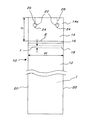
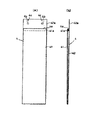
本発明の傘収納用袋10は、単一のシート部材が折り返されて側縁部20、20が互いに融着されて構成された前面側部分12及び背面側部分14を有し、背面側部分14は前面側部分12よりも所定寸法δだけ長い延長部分14aを備え、前面側部分12及び背面側部分14により収納部分Iを形成し、前面側部分の端部16は開口部Eを形成しており、収納部分I内部の領域で且つ背面側部分14に近い領域には横方向(傘収納用袋長手方向と直行する方向)に延在する(比較的幅寸法εが小さい)ベルト18が形成されており、前記延長部分14aに半円状の切欠部Ucが形成されている。
ここで、開口部Eを構成する前面側部分12の端部に折り返し部分16を形成することが好ましい。
このように切欠部Ucが形成されることにより、補強リブのような障害物等に邪魔されることなく袋収納装置に傘収納用袋を装着することができる。
The
Here, it is preferable to form the folded
By forming the cutout portion Uc in this way, the umbrella storage bag can be attached to the bag storage device without being obstructed by an obstacle such as a reinforcing rib.
係る構成を具備する本発明の傘収納用袋10によれば、横方向(傘収納用袋長手方向と直行する方向)に延在する(比較的幅寸法εが小さい)ベルト18が、開口部Eよりも(濡れた傘を収納する収納部分Iの)内側の領域で且つ背面側部分14に近い領域に形成されている。
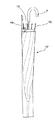
傘収納用袋10に傘を収納した際に、傘収納用袋10が傘から離脱して、傘収納用袋10のみが落下しようとしても、ベルト18が傘の骨Kbの部分や、傘の骨Kbと骨Kbとの間の領域に係合する図3参照ので、傘収納用袋10のみが落下してしまうことは無い。
According to the
Even when the
また本発明の傘収納用袋10、10Aは、単一のシート部材が折り返されて側縁部20、20が互いに融着されて構成された前面側部分12及び背面側部分14を有し、背面側部分14は前面側部分12よりも所定寸法δだけ長い延長部分14aを備え、前面側部分12及び背面側部分14により収納部分Iを形成し、前面側部分の端部16は開口部Eを形成しており、前記延長部分14aには貫通孔22が形成されており、該貫通孔22の周縁の一部に突起状の(例えば概略「くさび」状に形成された)融着部分24が形成され、貫通孔22と延長部分14aの端部との間の領域にはミシン目26が形成されており、前記延長部分14aに半円状の切欠部Ucが形成されている。
Further, the
係る構成を具備する本発明の傘収納用袋10、10Aによれば、貫通孔22に形成された融着箇所24により、袋10、10Aを多数重ねて取り扱う(例えば100枚ずつを1ユニットとして取り扱う)際に、個々の袋10、10Aがユニットから分離してしまうことが無い。
According to the
図28に示すように、従来の傘収納袋10Jでは、ビニール帯(いわゆる「ビニ帯」)Bやひもで結わえる必要があるので、その作業の分だけ労力及びコストが掛かってしまう。これに対して、本発明の傘収納用袋10、10Aでは融着箇所24を形成しているので、係る作業は不要となる。
融着箇所24は、例えば、多数枚(例えば100枚)重ねた本発明の傘収納用袋10、10Aを高温のカッタで切り欠くことにより形成されるので、高温のカッタで切り裂く際に、重ねられた多数の傘収納用袋10、10Aの素材が溶融されて、融着箇所24で一体化される。
融着部分24により一体的に取り扱い可能となった多数の袋10、10A或いはユニットは、例えば特許文献1で示す様な傘の袋収納装置に設けられた2本のピンを貫通孔に挿入することにより、傘の袋収納装置にセットされる。
As shown in FIG. 28, in the conventional
The fused
A large number of
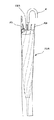
また、本発明の傘収納用袋10、10Aではミシン目26が形成されているので、当該袋10、10Aに傘を挿入した後、傘を引っ張ることにより、ミシン目26が破れて傘袋10、10Aは、傘の袋収納装置から確実に外れる図4参照。換言すれば、本発明の傘収納用袋10、10Aであれば、傘の袋収納装置から傘ごと分離する際に、袋の破片等が残留することが無いので、多数の袋10、10A或いはユニットを補充する際に、従来技術に比較して、余分な労力が掛からない。
In addition, since the
本発明の作用効果を以下に列挙する。
(1) 傘収納用袋の横方向に延在するベルトが、開口部よりも内側の領域で且つ背面側部分に近い領域に形成されており、傘収納用袋に傘を収納した際に、傘収納用袋が傘から離脱して、傘収納用袋のみが落下しようとしても、ベルトが傘の骨の部分や、傘の骨と骨との間の領域に係合するので、傘収納用袋のみが落下してしまうことは無い。
(2) 傘収納用袋に設けた、貫通孔に形成された融着箇所により、袋を多数重ねて取り扱う際に、個々の袋が重ねた束から分離してしまうことが無い。
(3) 従来の傘収納袋ように、ビニール帯やひもで結わえる必要はなく、そうした作業は不要となり、その結果コストを削減することが出来る。
(4) 傘収納用袋の貫通孔と袋の端部を結ぶミシン目が形成されているので、当該袋に傘を挿入した後、傘を引っ張ることにより、ミシン目が破れて傘袋は、傘の袋収納装置から確実に外れる。換言すれば、本発明の傘収納用袋であれば、傘の袋収納装置から傘ごと分離する際に、袋の破片等が残留することが無いので、多数の袋、或いはユニットを補充する際に、従来技術に比較して、破片の後片付けや掃除等の余分な労力が掛からない。
The effects of the present invention are listed below.
(1) The belt extending in the lateral direction of the umbrella storage bag is formed in a region inside the opening and in a region close to the back side portion, and when the umbrella is stored in the umbrella storage bag, Even if the umbrella storage bag is detached from the umbrella and only the umbrella storage bag is about to fall, the belt engages with the bone part of the umbrella or the region between the bones of the umbrella, Only the bag will not fall.
(2) When a large number of bags are stacked and handled by the fused portions formed in the through holes provided in the umbrella storage bag, the individual bags are not separated from the stacked bundle.
(3) Unlike conventional umbrella storage bags, there is no need to tie them with vinyl belts or strings, so that such work is not necessary, and as a result, costs can be reduced.
(4) Since the perforation connecting the through hole of the umbrella storage bag and the end of the bag is formed, the perforation is broken by pulling the umbrella after inserting the umbrella into the bag. Removes securely from the umbrella bag storage device. In other words, in the case of the umbrella storage bag of the present invention, when the umbrella is separated from the umbrella bag storage device, bag fragments or the like do not remain, so when a large number of bags or units are replenished. In addition, extra labor such as cleaning up and cleaning the fragments is not required as compared with the prior art.
以下、添付図面を参照して、本発明の実施形態について説明する。 Embodiments of the present invention will be described below with reference to the accompanying drawings.
図1〜図4を参照して、本発明の第1実施形態に係る傘収納用袋について説明する。 With reference to FIGS. 1-4, the umbrella storage bag which concerns on 1st Embodiment of this invention is demonstrated.
図1及び図2は、本発明の第1実施形態に係る傘収納用袋の外観図と、断面図を示している。
図1及び図2において、全体を符号10で示す傘収納用袋(以降、単に「袋」と略記する)は、その開口部が矢印Eで示されている。
FIG.1 and FIG.2 has shown the external view and sectional drawing of the umbrella storage bag which concern on 1st Embodiment of this invention.
1 and 2, an opening for an umbrella storage bag (hereinafter simply abbreviated as “bag”) indicated by
袋10はポリエチレン製である。濡れた傘を収納しても水が漏れ出ることが無く、しかも、比較的安価で且つ加工が容易だからである。但し、袋10の材料としては、ポリエチレンに限定されるものではない。例えば、機械部品のように、袋自体の臭いが問題にならない場合であれば、ビニール等で製造することも可能である。
The
袋10は、単一のシート状材料(ポリエチレン)を2つ折り返した様な概略形状をしており、前面側部分12と背面側部分14とが結合された構造を有している。そして、袋10の内側、すなわち濡れた傘を収納する収納部分は、符号Iで示されている。
ここで、前面側部分12の開口部E(前面側部分の端部)は、符号16で示す折り返し部分を有している。
The
Here, the opening E (the end of the front side portion) of the
前面側部分12は背面側部分14に対して、寸法δだけ短くなっている。そして、背面側部分14が前面側部分12よりも長い部分、即ち延長部分14a(寸法δの領域)には、背面側部分14を貫通する開口(貫通孔)22が形成されている。
そして、貫通孔22には、その周縁の一部に突起状の融着部分24、例えば概略「くさび」状に形成された融着部分24が設けられている。
The
The through-
さらに、貫通孔22の収納部分Iから離隔する方向(図1では上方)には、貫通孔22から袋の上端を結び、袋の長手方向に平行なミシン目26が形成されている。
Further, in the direction away from the storage portion I of the through hole 22 (upward in FIG. 1), a
開口部E(前面側部分の端部)よりも(収納部分Iの)内側の箇所には、比較的幅寸法εが小さいベルト18が設けられている。このベルト18は、前面側部分12よりも背面側部分14近傍に配置されている。
A
ここで、図1及び図2で示す袋によれば、袋10内に濡れた傘Kを入れた後、袋10が傘Kから抜け出て落下しそうになった場合には、図3で示す様に、ベルト18が傘の骨Kb或いは傘の骨Kb間の領域に引っ掛かる。そのため、袋10が傘Kから落下しようとしても、ベルト18が傘の骨Kbに引っ掛かっているため、袋10が傘から抜け落ちてしまうことが防止される。
Here, according to the bag shown in FIG. 1 and FIG. 2, when the wet umbrella K is put in the
また、特に図1で示す様に、上述した袋10では、貫通孔22に融着箇所24が形成されている。係る融着箇所24を形成する態様の詳細は後述する。
融着箇所24を形成することにより、上述した袋10を多数重ねて取り扱う(例えば100枚ずつを1ユニットとして取り扱う)際に、個々の袋10がユニットから分離してしまうことが無い。
換言すれば、融着箇所24が無い従来の傘収納袋10Jでは、図30で示す様にビニール帯(いわゆる「ビニ帯」)Bやひもで結わえる必要があるので、その作業の分だけ労力及びコストが掛かってしまう。これに対して、図1で示す様な融着箇所24を形成すれば、係る作業は不要となる。
In particular, as shown in FIG. 1, in the above-described
By forming the fused
In other words, in the conventional
融着部分24により一体的に取り扱い可能となった多数の袋10は(袋10のユニットは)、例えば特許文献1で示す様な傘の袋収納装置に設けられた2本のピンを貫通孔22、22に挿入することにより、傘の袋収納装置にセットされる。
ここで、図1で示す袋10にはミシン目26が形成されているので、図4に示すように、当該袋10に傘を挿入した後、傘を引っ張ることにより、ミシン目26が破れて傘袋10は、傘の袋収納装置30のピン48から確実に外れる。換言すれば、図1で示す袋10であれば、傘の袋収納装置30から傘ごと分離する際に、袋の破片等が残留することが無いので、多数の袋10(袋10のユニット)を補充する際に、従来技術に比較して、余分な労力が掛からないのである。
A large number of bags 10 (units of the bags 10) that can be handled integrally by the fused
Here, since the
図5及び図6は、本発明の第2実施形態に係る傘の収納用袋10Aを示している。
この袋10Aは、図1及び図2で示す袋10と概略同様な構成を具備している。但し、図1及び図2で示す袋10では、ベルト18は開口部Eよりも収納部分Iの内側の箇所(図1では開口部Eの下側の箇所)に設けられているのに対して、図5及び図6で示す袋10Aでは、同様なベルト18Aは開口部Eよりも貫通孔22の近い側(図5では開口部Eよりも上方の箇所:背面側部分14の端部側)に設けられている点が相違している。
その他の構成については、袋10Aは、図1及び図2で示す袋10と同様である。
5 and 6 show an
This
About another structure, 10 A of bags are the same as that of the
図5及び図6で示す袋10Aにおいても、図示しない傘から脱落してしまうことが防止される。
(図3に関連して上述したのと同様、)図7で示す様に、ベルト18Aが傘の骨Kb或いは骨Kb、Kb間の領域に引っ掛かるからである。
図5及び図6で示す袋10Aにおけるその他の作用効果についても、図1及び図2で示す袋10と同様である。
The
This is because, as shown in FIG. 7 (as described above with reference to FIG. 3), the
Other functions and effects of the
ここで、(例えば特許文献1で示す様な)傘の袋収納装置においては、その機種によっては、貫通孔22、22間の領域と干渉してしまう部位を有している場合がある。
その様な傘の袋収納装置である場合、図1〜図6で示す様な袋10、10Aはセットすることが出来なくなってしまう。
図8で示す第3実施形態は、その様な状況に対処するために提案されたものである。
Here, an umbrella bag storage device (for example, as shown in Patent Document 1) may have a portion that interferes with the region between the through
In the case of such an umbrella bag storage device, the
The third embodiment shown in FIG. 8 is proposed to deal with such a situation.
図8で示す第3実施形態に係る袋10Bでは、貫通孔22及びミシン目26の間の領域に、大きな半円形状の切欠部Ucが形成されている。
係る切欠部Ucを有する袋10Bは、複数毎(例えば100枚)重ねても、切欠部Ucの部分は空間となっている。そのため、上記したようなタイプの(例えば、切欠き部Ucの位置に、補強リブが配置してある)傘の袋収納装置にセットしても、袋収納装置の部位(補強リブ)等と干渉してしまうことが防止される。
In the
Even if a plurality of (for example, 100) bags 10B having such cutout portions Uc are stacked, the cutout portion Uc is a space. Therefore, even if it is set in an umbrella bag storage device of the type described above (for example, a reinforcing rib is disposed at the position of the notch Uc), it interferes with a portion (reinforcing rib) of the bag storage device, etc. Is prevented.
次に、図9〜図27を参照して、上述した傘収納用袋10を製造する参考例について説明する。
Next, a reference example for manufacturing the
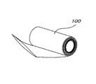
袋10は、図9の符号イ、図10の符号100で示す様に、ロール状に巻き取られた長尺の筒状部材(図示の実施形態では、素材はポリエチレン)を加工することにより製造される。そして、係る「ロール状に巻き取られた長尺の筒状部材」は、原材料加工業者により販売されている市販品である。
The
図9を参照して傘収納用袋製造装置の全体構成を説明する。 With reference to FIG. 9, the overall configuration of the umbrella storage bag manufacturing apparatus will be described.
図9の符号イの箇所には、リール2にロール状に巻き取られた長尺のポリエチレン製の筒状部材100(図10を参照)が配置してある。
係る長尺の筒状部材(以下、「長尺材料」と表記)100が、引き出しローラ60、60により引き出される。
9, a long polyethylene tubular member 100 (see FIG. 10) wound around the reel 2 in a roll shape is disposed.
Such a long cylindrical member (hereinafter referred to as “long material”) 100 is pulled out by pulling
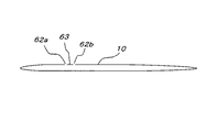
引き出された長尺材料100は、図9の符号ロ、及び図11〜図14で示す様に、カッタ64a、64bにより2箇所が切り裂かれ、切れ目62a、62bが形成される。
ここで、切れ目62bは、袋10の開口部Eを形成する。また、切れ目62aと切れ目62bで挟まれた領域63が、ベルト18を構成する。
なお、図12は、図11で模式的に示す工程をより詳細に説明している。
As shown in FIG. 9B and FIGS. 11 to 14, the drawn
Here, the
Note that FIG. 12 explains the process schematically shown in FIG. 11 in more detail.
図11、及び図12において、カッタ64bで切り裂かれた切れ目62bの位置は、図1で示す寸法δ(背面側部分14が前面側部分12よりも長い部分の寸法)によって決定される。換言すれば、長尺部材100の図11の左端部からカッタ64bまでの寸法LCは、図1で示す寸法δにより一義的に決定される。
なお、図12において矢印Xは長尺部材100が引っ張られて移動する方向を表している。
11 and FIG. 12, the position of the
In FIG. 12, an arrow X represents a direction in which the
図12及び、図12のY矢視図である図13において、長尺部材100の上方のシート100U(袋に製造された場合の前面側部分12に相当)と、下方のシート100L(袋に製造された場合の背面側部分14に相当)の間にはカッタ受け部材Cが挿入されている。
このカッタ受け部材Cは、カッタ64a、64bが長尺部材100を上下2枚とも切ってしまわない様に、2枚のポリエチレンシート間(100Uと100Lの間)に挿入されている。
12 and FIG. 13 as viewed from the direction of the arrow Y in FIG. 12, an upper sheet 100U of the long member 100 (corresponding to the
The cutter receiving member C is inserted between the two polyethylene sheets (between 100 U and 100 L) so that the
一方、カッタ64a、64bの切っ先64cは第1の支持部材B1および第2の支持部材B2を介して、間接的に前記カッタ受け部材Cに接続され、そのカッタ受け部材Cの特定の位置Pに接するように配置される。
On the other hand, the cutting edge 64c of the
カッタ64a、64bには取付用孔64dが設けられ、カッタ64aとカッタ64bの間(紙面の表裏の方向の間)には前記ベルト18の幅εを確保出来るように図示しない取付け孔を設けたスペーサ65が挟み込まれており、カッタ側の取付用孔64dと図示しないスペーサの取付孔と、第1の支持部材B1側の長手方向に長径が配置された長孔B1bとを挿通するように図示しない1本のボルトでカッタ64a、64b及びスペーサ65が第1の支持部材B1に取り付けられる。
したがって、カッタ64はG矢印方向に回転することで切っ先の角度が調節出来、またF(図示の左右)方向にスライドも出来るので、カッタ受け部材Cに傷等が出来た場合は前記特定の位置Pを移すことも出来る。
The
Accordingly, the cutter 64 can be rotated in the direction of the arrow G to adjust the angle of the cutting edge, and can also be slid in the direction F (left and right in the figure). You can also move P.
また、前記第1の支持部材B1の他端には取付孔B1aが、第2の支持部材B2の一端には取付け孔B2aが設けてあり、その2つの取付孔B1a、B2aに1本のボルトを挿通するように連結しているので、第1の支持部材B1は取付け孔B2aの周りにJ矢印方向に回動可能となっている。そのため、前記カッタ64a、64bの切っ先64cは上下方向にも調整が可能である。
The other end of the first support member B1 is provided with a mounting hole B1a, and one end of the second support member B2 is provided with a mounting hole B2a. One bolt is provided in each of the two mounting holes B1a and B2a. Therefore, the first support member B1 is rotatable around the attachment hole B2a in the direction of arrow J. Therefore, the cutting edge 64c of the
また、例えば第1の指示部材B1と第2の支持部材B2の間に例えばアタッチメントを加えることにより、カッタ64の幅方向の位置、すなわち袋の素材である長尺の筒状部材の幅方向の位置を変更することも可能である。 Further, for example, by adding an attachment between the first indicating member B1 and the second support member B2, for example, the position in the width direction of the cutter 64, that is, the width direction of the long cylindrical member that is the material of the bag. It is also possible to change the position.
さらに、前記ベルト18の幅εは、前記スペーサ65の幅εを変えることによって変更可能である。
Further, the width ε of the
図11、図12により、切れ目62a、62bが形成された長尺部材を、模式的に図14で示す。
11 and 12, a long member in which cut
図9の符号ハで示す箇所では、図15及び図16で示す様に、切れ目62aで分離した部分66を矢印T方向に開く工程が行われる。
換言すれば、図15で示す工程では、部分66を、長尺部材100の傘収納用袋10の背面部14側に相当する領域14S側へ、展開する操作が行われる。
なお、部分66を背面部14相当領域14S側へ展開することにより、背面部14は前面部12よりも長くなるのである。
9, as shown in FIGS. 15 and 16, a step of opening the
In other words, in the process shown in FIG. 15, the operation of expanding the
Note that the
図15で説明した工程をより詳細に説明したのが図16である。図16において、先端が湾曲した展開用治具70を長尺部材100の符号66で示す部分へ押し当てる。
展開用治具70は、図16で示す例では、部分66を図16中左方に移動する力を付勢されており、当該部分66を背面部14に相当する領域14S側へ展開していく。
FIG. 16 illustrates the process described in FIG. 15 in more detail. In FIG. 16, the developing
In the example shown in FIG. 16, the unfolding
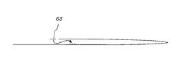
図9の符号ニで示す箇所では、図17で示す様に、切れ目62a、62b(図14および図15を参照)で挟まれた部分63を、ベルト18が配置されるべき位置(図1において、開口部Eよりも収納部I内側の位置であって、背面側部分14に相当する領域14Sに近接した位置)とせしめる工程が実行される。
9, the
図17で示す工程を具体的に示すのが、図18である。図18において、仮想線(破線)で示す部分63は、冶具74により、ベルト18(図1参照)が配置されるべき位置63c(図1において、開口部Eよりも収納部I内側の位置であって、背面側部分14に相当する領域14Sに近接した位置)まで移動される。
FIG. 18 specifically shows the process shown in FIG. In FIG. 18, a
ここで治具74は、図19に詳細を示すように、材料である長尺の筒状部材100(図10〜図12を参照)の長手方向に直角方向に2本の切込み74aを入れ、その2本の切込み74a、74aに挟まれた部分74bを紙面の上下いずれかの方向に一旦離隔させその後元の材料と同じ方向に曲げ返され、図18に示すようにその治具の横断面形状は、恰も溝74vが形成されるように構成される。そして、治具74は部分63をその溝74vに挟み込んだ状体で、ベルト18(図1参照)が配置されるべき位置63cまで移動する。
Here, as shown in detail in FIG. 19, the
図9の符号ホで示す箇所では、図20で示す様に、長尺部材100の、傘収納用袋10の前面部12側に相当する領域12Sにおいて、当該(前面側部分12に相当する)領域12Sの端部12S−Eが矢印T2で示す様に折り曲げられて、折り返し部16を形成する。
9, in the
図20で説明した工程をより詳細に説明したのが図21である。
図21において、長尺部材100における前面部相当領域12Sの端部12S−E(図20参照)が、折り曲げ用治具76により折り曲げ或いは折り返されて、折り返し部16を形成している。
この時点で、背面側部分14に相当する領域14Sは、前面側部分12に相当する領域12Sよりも、寸法δだけ長い延長部14aとなる。
FIG. 21 illustrates the process described in FIG. 20 in more detail.
In FIG. 21, the
At this point, the
図9の符号「ヘ」の箇所では、図1を参照して説明した貫通口22及びミシン目26を形成する。その具体的な態様が図22に示されている。
図22で示す様に、背面側部分14に相当する領域14Sが前面側部分12に相当する領域12Sよりも長い部分、すなわち寸法δの領域に、貫通孔22を形成するためのカッタ82と、ミシン目26を形成するためのカッタ84とが押圧される様に構成されている。
9, the through
As shown in FIG. 22, a
貫通孔22を形成するためのカッタ82は、図22では明確に示されてはいないが、円筒状のカッタ本体の先端に、鋸状の複数の歯が形成されたものである。
カッタ82及び84は、図1の袋10に示すように貫通孔22の中心から袋10の端部に連続してミシン目26が成形されるように、図23で示すカッタ取付け治具85に1対のカッタ82及び84が配置してある。
Although the
The
また、前記ミシン目26を形成するためのカッタ84は、貫通孔22を形成するためのカッタ82側に最も近い歯84aの先端が最下位置で、カッタ82の反対側で最も遠い歯84dの先端が最上位置となるように、全ての歯の先端位置の配置が傾斜するように構成されている。このように各歯の先端が傾斜して配置されているのは、各歯の先端が1本ずつ素材である長尺部材100に当たって、長尺部材100に食込み易くするためである。即ち、当り始めの面圧を高めることで食込み易く(ミシン目を形成し易く)したものである。
Further, the
図9の符号「ヘ」の箇所を通過した段階で、長尺部材100は、図24で示す様な状態、すなわち図1の袋10が側縁部20で区切られておらず、そのまま図1の左右方向で連続した状態となっている。
そして、図9中、符号86で示す領域で、図1で示すような(但し、後述するように、融着部分24は依然として形成されていない)1枚ずつの傘収納袋10に分離される。
At the stage of passing through the portion “f” in FIG. 9, the
Then, in the region indicated by
図9の符号86で示す領域は、送りローラ87、87と、溶断用カッタ88及びその受け部材90と、送り用の上下のコンベア機構92、94で構成されている。
The area denoted by
送り用ローラ87、87は、連続した状態の長尺部材100を、傘収納用袋10の幅W(図1及び図24参照)だけ、正確に送る。この送り用ロール87、87で寸法W分だけ正確に長尺部材100を送ることにより、次の溶断用カッタ88及びその受け部材90は、傘収納用袋10を、正確に幅Wずつ切断することが出来る。換言すれば、溶断用カッタ88及びその受け部材90により、図24において符号Mcで示す溶断位置で、背面側部分14に相当する領域14Sと前面側部分12に相当する領域12Sとを融着しつつ、長尺部材100を切断する。
The
溶断用カッタ88及びその受け部材90において、溶断用カッタ88は、その表面がポリエチレンが溶融する温度以上となる様に加熱されている。加熱の手法は、公知の一般的な手法(例えば、電気的な加熱)でよい。
カッタ88は、その受け部材90と協働する事により、比較的薄い長尺部材100が、確実に切断されるように構成されている。そして、長尺部材100が袋10の幅W(図1及び図24参照)だけ切断された際に、カッタ88の高温により、ポリエチレン製の長尺部材100が溶融して、傘収納用袋10の側縁部20が確実に接着する。
In the
The
溶断用カッタ88及びその受け部材90により長尺部材100を切断した段階で、図1で示すような傘収納用袋10が完成する。そこで、送り用のコンベア機構92、94により、完成した物品収容用袋10を1枚ずつ、図9において左方に存在する部材240側へ送り出す。
At the stage where the
部材240は、図1において説明した融着部分24を形成する。
部材240で融着部分24を形成するための構成については、図25〜図28を参照して説明する。
The
A configuration for forming the fused
図25は、融着部分を形成するための治具240の、先端が塞がれた2本の円筒状の突起102を、袋10を所定枚数(例えば100枚)重ねて、その袋10の貫通孔22に、挿通する工程を立体的に示した図である。
なお、図25は、一旦所定枚数に重ねられた状態の束の袋10をまとめて治具240の突起102に挿通させる実施例であるが、図9のラインの最終過程で袋10の貫通孔22が1枚づつ自動的に治具240の突起102に挿通させられるように構成してもよい。
FIG. 25 shows a case in which a predetermined number (for example, 100) of
FIG. 25 shows an embodiment in which a bundle of
前記融着部分24(図1を参照)を形成するための治具240には、治具本体240aの上面に一対の前記先端が塞がれた円筒状の突起102が長尺部材100の流れ(図25において、白抜きの矢印方向)に直交する方向に並列に突設している。
In the
前記突起102には、長尺部材100の流れの反対側に溝104が形成してある。
また、図25を上方から平面的に見た場合に、突起102の円筒断面からはみ出し、長尺部材の流れの反対方向に前記溝104と略同じ幅の切れ込み部105が形成されている。
A
In addition, when FIG. 25 is viewed from above in plan view, a
前記溝104には、図26に示すように、融着部分形成用の加熱カッタ110の加熱される刃110Eが下方から上方に向かって上昇する。図27は、カッタ110が上昇しきった状態を示している。すなわち、図27の状態は、溝104から刃110Eが露出する部分の袋10を切削しつつ溶融して、溶着箇所24を形成している。
In the
次に、図5及び図6を参照して説明した第2実施形態に係る傘収納用袋10Aの製造について説明する。
Next, manufacture of the
図5及び図6の傘収納用袋10Aの製造方法は、図9〜図27を参照して上述した態様と概略同様である。
しかし、図1及び図2の袋10の製造に際して、図18では、部分63を図1の開口部Eよりも収納部分I内側で且つ背面側部分に対応する領域14Sに近い位置63cに移動している点が、図5及び図6の袋10Aの製造に際しては相違している。
The manufacturing method of the
However, when manufacturing the
図5及び図6の袋10Aを製造する場合には、切れ目62a、62bで挟まれた領域63は、図18と同一構成の冶具により、図5においてバンド18Aが配置される位置63Ac、すなわち、図5において開口部Eよりも貫通孔22側の位置であって、背面側部分14に対応する領域14Sに近接した位置まで移動される。
When manufacturing the
図28では、第3実施形態に係る袋10Bの製造の参考例を示している。
例えば、図25〜図27を参照して説明された融着部分24形成に際して、切欠部Ucと対応する形状のカッタ120を例えば上方より、袋10Bの束に押し込むことにより、切欠部Ucを形成すればよい。
なお、図28では当該カッタ120のみ、便宜上立体的に示している。
In FIG. 28, the reference example of manufacture of the bag 10B which concerns on 3rd Embodiment is shown.
For example, when forming the fused
In FIG. 28, only the
但し、このカッタ120は加熱切断するタイプのものは不都合である。仮にカッタ120で切欠き部Ucを溶断してしまうと、束内の袋10B同士の結合が強固になりすぎて、傘を収納して袋を束から離脱させることが困難になってしまうからである。
従って、カッタ120は加熱しない通常のカッタを用いる。但し、袋10Bを多数枚積み重ねたものを切断するため、鋭利で且つ頑丈な刃先を有するものが好適である。
However, this type of
Accordingly, the
図示の実施形態はあくまでも例示であり、本発明の技術範囲を限定する趣旨の記述ではないことを付言する。 It should be noted that the illustrated embodiment is merely an example, and is not a description of the purpose of limiting the technical scope of the present invention.
2・・・リール
10、10A・・・傘収納用袋
12・・・前面側部分
14・・・背面側部分
16・・・折返し部分
20・・・側縁部
62a、62b・・・切れ目
64a、64b・・・カッタ
74・・・治具
76・・・折り曲げ用治具
87・・・送りローラ
88・・・溶断用カッタ
100・・・長尺部材
2 ...
Claims (2)
Priority Applications (1)
| Application Number | Priority Date | Filing Date | Title |
|---|---|---|---|
| JP2007009722A JP4023552B2 (en) | 2007-01-19 | 2007-01-19 | Umbrella storage bag |
Applications Claiming Priority (1)
| Application Number | Priority Date | Filing Date | Title |
|---|---|---|---|
| JP2007009722A JP4023552B2 (en) | 2007-01-19 | 2007-01-19 | Umbrella storage bag |
Related Parent Applications (1)
| Application Number | Title | Priority Date | Filing Date |
|---|---|---|---|
| JP2003002129A Division JP3923015B2 (en) | 2003-01-08 | 2003-01-08 | Umbrella storage bag manufacturing apparatus and manufacturing method |
Publications (2)
| Publication Number | Publication Date |
|---|---|
| JP2007098178A JP2007098178A (en) | 2007-04-19 |
| JP4023552B2 true JP4023552B2 (en) | 2007-12-19 |
Family
ID=38025646
Family Applications (1)
| Application Number | Title | Priority Date | Filing Date |
|---|---|---|---|
| JP2007009722A Expired - Lifetime JP4023552B2 (en) | 2007-01-19 | 2007-01-19 | Umbrella storage bag |
Country Status (1)
| Country | Link |
|---|---|
| JP (1) | JP4023552B2 (en) |
Cited By (1)
| Publication number | Priority date | Publication date | Assignee | Title |
|---|---|---|---|---|
| WO2019131714A1 (en) | 2017-12-26 | 2019-07-04 | 新倉計量器株式会社 | Umbrella bag bundle, umbrella bag bundle holding structure, and bag-opening device |
Families Citing this family (1)
| Publication number | Priority date | Publication date | Assignee | Title |
|---|---|---|---|---|
| JP6359154B1 (en) * | 2017-06-13 | 2018-07-18 | 株式会社Harman・Products | Food container packaging equipment |
-
2007
- 2007-01-19 JP JP2007009722A patent/JP4023552B2/en not_active Expired - Lifetime
Cited By (4)
| Publication number | Priority date | Publication date | Assignee | Title |
|---|---|---|---|---|
| WO2019131714A1 (en) | 2017-12-26 | 2019-07-04 | 新倉計量器株式会社 | Umbrella bag bundle, umbrella bag bundle holding structure, and bag-opening device |
| KR20200093684A (en) | 2017-12-26 | 2020-08-05 | 니이구라 스케일 가부시끼가이샤 | Umbrella bag set, holding structure of umbrella bag set, and bag opening device |
| US11083260B2 (en) | 2017-12-26 | 2021-08-10 | Niikura Scales Co., Ltd. | Umbrella bag bundle, holding structure for umbrella bag bundle, and bag opening device |
| EP3895577A1 (en) | 2017-12-26 | 2021-10-20 | Niikura Scales Co., Ltd. | Umbrella bag bundle, holding structure for umbrella bag bundle, and bag opening device |
Also Published As
| Publication number | Publication date |
|---|---|
| JP2007098178A (en) | 2007-04-19 |
Similar Documents
| Publication | Publication Date | Title |
|---|---|---|
| JP5242930B2 (en) | Method for manufacturing upper wrapping material and pack including manufactured upper wrapping material | |
| JP7101049B2 (en) | Food packaging bag | |
| JP4023552B2 (en) | Umbrella storage bag | |
| WO2001032527A1 (en) | Package of cylindrical article and production method therefor | |
| JP6713278B2 (en) | Winding device and method of manufacturing wound body | |
| JP5308983B2 (en) | Slot type optical cable and method of disassembling slot type optical cable | |
| JP3923015B2 (en) | Umbrella storage bag manufacturing apparatus and manufacturing method | |
| EP2275356A1 (en) | Method for manufacturing draw string bags | |
| TWI826410B (en) | Umbrella bag bundle, umbrella bag bundle holding structure, and bag opening device | |
| JP6078837B2 (en) | Packaging bag and packaging bag bundle | |
| WO2016060203A2 (en) | Manufacturing method for bag, and portable bag | |
| WO2016075719A1 (en) | Card protective sleeve | |
| JP2008233890A (en) | Shrink label, manufacturing method thereof, and die cutter | |
| JP4925478B2 (en) | Cigarette pack parcel | |
| TWI331977B (en) | ||
| FR2690377A1 (en) | Device for welding strips of sheet of thermoplastic material. | |
| JP4964228B2 (en) | Apparatus and method for joining the ends of two flat tubular webs | |
| JP4253774B1 (en) | Granule storage bag | |
| JP5956128B2 (en) | Pocket tissue package and manufacturing method thereof | |
| JP7528534B2 (en) | Method for attaching oral appliance cover and packaging bag | |
| JP6259015B2 (en) | Packaging container | |
| JP7083158B2 (en) | Umbrella bag bundle, holding structure of umbrella bag bundle, bag opening device | |
| KR100947370B1 (en) | Disposable gloves, manufacturing apparatus for disposable gloves and manufacturing method | |
| JP7024297B2 (en) | Purse bag manufacturing equipment and manufacturing method | |
| JP3193045U (en) | Protective bag for cards |
Legal Events
| Date | Code | Title | Description |
|---|---|---|---|
| A621 | Written request for application examination |
Free format text: JAPANESE INTERMEDIATE CODE: A621 Effective date: 20070119 |
|
| A521 | Request for written amendment filed |
Free format text: JAPANESE INTERMEDIATE CODE: A523 Effective date: 20070123 |
|
| A131 | Notification of reasons for refusal |
Free format text: JAPANESE INTERMEDIATE CODE: A131 Effective date: 20070523 |
|
| A521 | Request for written amendment filed |
Free format text: JAPANESE INTERMEDIATE CODE: A523 Effective date: 20070717 |
|
| TRDD | Decision of grant or rejection written | ||
| A01 | Written decision to grant a patent or to grant a registration (utility model) |
Free format text: JAPANESE INTERMEDIATE CODE: A01 Effective date: 20070925 |
|
| A61 | First payment of annual fees (during grant procedure) |
Free format text: JAPANESE INTERMEDIATE CODE: A61 Effective date: 20070925 |
|
| R150 | Certificate of patent or registration of utility model |
Free format text: JAPANESE INTERMEDIATE CODE: R150 Ref document number: 4023552 Country of ref document: JP Free format text: JAPANESE INTERMEDIATE CODE: R150 |
|
| FPAY | Renewal fee payment (event date is renewal date of database) |
Free format text: PAYMENT UNTIL: 20101012 Year of fee payment: 3 |
|
| FPAY | Renewal fee payment (event date is renewal date of database) |
Free format text: PAYMENT UNTIL: 20131012 Year of fee payment: 6 |
|
| R250 | Receipt of annual fees |
Free format text: JAPANESE INTERMEDIATE CODE: R250 |
|
| R250 | Receipt of annual fees |
Free format text: JAPANESE INTERMEDIATE CODE: R250 |
|
| R250 | Receipt of annual fees |
Free format text: JAPANESE INTERMEDIATE CODE: R250 |
|
| R250 | Receipt of annual fees |
Free format text: JAPANESE INTERMEDIATE CODE: R250 |
|
| EXPY | Cancellation because of completion of term |